WO2020115947A1 - 光学フィルム用巻き芯、光学フィルムロール体、及び光学フィルムの連続供給方法 - Google Patents
光学フィルム用巻き芯、光学フィルムロール体、及び光学フィルムの連続供給方法 Download PDFInfo
- Publication number
- WO2020115947A1 WO2020115947A1 PCT/JP2019/031130 JP2019031130W WO2020115947A1 WO 2020115947 A1 WO2020115947 A1 WO 2020115947A1 JP 2019031130 W JP2019031130 W JP 2019031130W WO 2020115947 A1 WO2020115947 A1 WO 2020115947A1
- Authority
- WO
- WIPO (PCT)
- Prior art keywords
- optical film
- film
- dummy
- optical
- roll body
- Prior art date
- Legal status (The legal status is an assumption and is not a legal conclusion. Google has not performed a legal analysis and makes no representation as to the accuracy of the status listed.)
- Ceased
Links
Images








Classifications
-
- B—PERFORMING OPERATIONS; TRANSPORTING
- B65—CONVEYING; PACKING; STORING; HANDLING THIN OR FILAMENTARY MATERIAL
- B65H—HANDLING THIN OR FILAMENTARY MATERIAL, e.g. SHEETS, WEBS, CABLES
- B65H75/00—Storing webs, tapes, or filamentary material, e.g. on reels
- B65H75/02—Cores, formers, supports, or holders for coiled, wound, or folded material, e.g. reels, spindles, bobbins, cop tubes, cans, mandrels or chucks
- B65H75/18—Constructional details
- B65H75/28—Arrangements for positively securing ends of material
-
- B—PERFORMING OPERATIONS; TRANSPORTING
- B65—CONVEYING; PACKING; STORING; HANDLING THIN OR FILAMENTARY MATERIAL
- B65H—HANDLING THIN OR FILAMENTARY MATERIAL, e.g. SHEETS, WEBS, CABLES
- B65H19/00—Changing the web roll
- B65H19/10—Changing the web roll in unwinding mechanisms or in connection with unwinding operations
-
- B—PERFORMING OPERATIONS; TRANSPORTING
- B65—CONVEYING; PACKING; STORING; HANDLING THIN OR FILAMENTARY MATERIAL
- B65H—HANDLING THIN OR FILAMENTARY MATERIAL, e.g. SHEETS, WEBS, CABLES
- B65H19/00—Changing the web roll
- B65H19/22—Changing the web roll in winding mechanisms or in connection with winding operations
- B65H19/29—Securing the trailing end of the wound web to the web roll
-
- G—PHYSICS
- G02—OPTICS
- G02B—OPTICAL ELEMENTS, SYSTEMS OR APPARATUS
- G02B5/00—Optical elements other than lenses
- G02B5/30—Polarising elements
-
- B—PERFORMING OPERATIONS; TRANSPORTING
- B65—CONVEYING; PACKING; STORING; HANDLING THIN OR FILAMENTARY MATERIAL
- B65H—HANDLING THIN OR FILAMENTARY MATERIAL, e.g. SHEETS, WEBS, CABLES
- B65H2701/00—Handled material; Storage means
- B65H2701/10—Handled articles or webs
- B65H2701/17—Nature of material
- B65H2701/175—Plastic
- B65H2701/1752—Polymer film
Definitions
- the present invention relates to a core used for winding an optical film, a roll body around which the optical film is wound, and the like.
- optical films have been used for displays such as liquid crystal display devices and organic display devices.
- the optical film include a polarizing film, a polarizing plate including a polarizing film, a retardation film, an antiglare film, and the like.
- the optical film is usually a long strip. This long strip optical film is processed by a processing machine and used. At the time of processing, in order to supply a new optical film to the processing machine following the preceding optical film, the leading end of the new optical film is joined to the trailing end of the preceding optical film. There is. Such joining is also called splicing.
- adhesive tape attachment or heat welding is known (Patent Document 1).
- Patent Document 2 discloses a continuous supply device that continuously supplies an optical film by joining a preceding optical film and a new optical film. Specifically, with reference to FIG. 7 of Patent Document 2, the first optical film pulled out from the first roll, the first suction means 103 and the first fixing member 102, and the conveyance side suction means 303 and the conveyance. Adsorption is fixed by the side fixing member 302. The first optical film between the two fixing members is cut by the first cutting means 101. On the other hand, the front end portion of the second optical film pulled out from the second roll is fixed by the second suction means 203 and the second fixing member 202.
- the rear end of the first optical film fixed by the transport-side suction means 303 and the transport-side fixing member 302 is attached to the front end of the second optical film fixed by the second suction means 203 and the second fixing member 202. After the movement, the rear end of the first optical film and the front end of the second optical film are joined with a tape.
- the continuous feeding device of Patent Document 2 is a device capable of continuously feeding the optical films by joining the two optical films as described above.
- the end material of the first optical film that is not joined to the second optical film remains.
- the end material is from the portion fixed on the first roll to the portion fixed by the first suction means 103 and the first fixing member 102 on the first optical film.
- this scrap is described as the minimum remaining amount. Such scraps are discarded after joining the two optical films.
- it is required to use the optical film as completely as possible.
- An object of the present invention is to provide a core for an optical film, an optical film roll body, and a continuous supply method of the optical film, which can join the optical films without waste.
- the optical film winding core of the present invention includes a core member and a dummy film wound around the core member and having a tip end portion to which the optical film can be connected.
- a preferred core for an optical film of the present invention the tip end portion of the dummy film is temporarily fixed to prevent development.
- a preferred core for an optical film according to the present invention has a dummy film layer formed around the core member by winding the dummy film around the core member for one or more rounds.
- a temporary fixing tape is attached across the surface of the dummy film layer, and a cutting auxiliary line is formed on the temporary fixing tape along the edge of the tip end of the dummy film or in the vicinity thereof. There is.
- an optical film roll body is provided.
- the optical film roll body of the present invention has any one of the above optical film cores and an optical film wound around the core, and the rear end portion of the optical film and the leading end portion of the dummy film are The optical film is wound around the winding core in a connected state.
- another dummy film is connected to the leading end of the optical film.
- a method for continuously supplying an optical film is provided.
- the continuous supply method of the optical film of the present invention after pulling out the optical film from any one of the optical film rolls, separate the optical film from the dummy film, and join the optical film and another optical film. Transport.
- two optical films can be joined without wasting the optical film. Further, by using the optical film roll body of the present invention, two optical films can be joined without wasting the optical film.
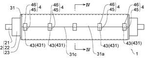
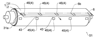
- FIG. 1 is a perspective view of an optical film core according to an embodiment of the present invention.
- FIG. 4 is an enlarged sectional view taken along line IV-IV in FIG.
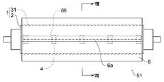
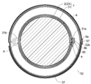
- the front view of the optical film roll body concerning one embodiment of the present invention.
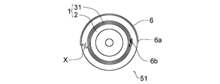
- FIG. 7 is an enlarged sectional view taken along line VIII-VIII of FIG.
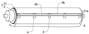
- FIG. 6 is a perspective view showing a process of connecting an optical film to a core for an optical film.
- FIG. 6 is a perspective view showing a state in which the temporary fixing tape is broken and the dummy film is pulled out.
- FIG. 4 is a reference side view showing a process of winding the optical film around the core after manufacturing the optical film.
- the reference side view which shows the continuous supply apparatus before joining two optical films.
- the reference side view which shows the process of joining two optical films in a continuous supply apparatus.
- the reference side view which shows the process of joining two optical films and continuously supplying an optical film in a continuous supply apparatus.
- the rear end portion refers to the end portion of the end portion of the film that is closer to the core member, and the front end portion is the end portion on the side opposite to the rear end portion (on the side away from the core member). End).
- the terms “first” and “second” may be added to the beginning of the terms, but the terms “first” and the like are added only to distinguish the terms and have a special meaning such as the order or superiority or inferiority. Do not have.
- the numerical range represented by “lower limit value XXX to upper limit value YYY” means a lower limit value XXX or more and an upper limit value YYY or less. When a plurality of the numerical ranges are described separately, it is possible to select an arbitrary lower limit value and an arbitrary upper limit value and set "an arbitrary lower limit value to an arbitrary upper limit value”.
- Winding core for optical film 1 is a perspective view of a core 1 for an optical film of the present invention, FIG. 2 is a front view thereof, FIG. 3 is a side view thereof, and FIG. 4 is a sectional view taken along line IV-IV. It is an enlarged sectional view.
- the optical film winding core 1 of the present invention is used with an optical film wound around it, as will be described later. 1 to 4, an optical film winding core 1 includes a core member 2 and a dummy film 31 wound around the core member 2 and having a tip portion 31a to which the optical film can be connected. And a film 31. If necessary, in order to prevent the wound dummy film 31 from unfolding from the core member 2, a temporary fixing means is provided at the tip of the dummy film 31.
- the core member 2 is a member around which the dummy film 31 is wound.
- the core member 2 is not particularly limited as long as the dummy film 31 can be wound around the core member 2.
- the core member 2 has, for example, a support shaft 21 and an outer cylinder portion 23 around which the dummy film 31 is wound. If necessary, an intermediate tubular portion 22 may be interposed between the support shaft 21 and the outer tubular portion 23.
- the support shaft 21 is composed of, for example, a circular shaft made of metal such as iron or stainless steel.
- the intermediate tubular portion 22 is provided around the support shaft 21.
- the intermediate tubular portion 22 may be fixedly provided on the support shaft 21, or may be rotatably provided on the support shaft 21.
- the intermediate tubular portion 22 is fixed to the support shaft 21.
- the outer shape of the intermediate tubular portion 22 is usually cylindrical as shown, but may be square tubular or the like (not shown).
- the outer tubular portion 23 has a tubular shape larger in diameter than the intermediate tubular portion 22, and is provided around the intermediate tubular portion 22.
- the outer tubular portion 23 may be fixedly provided to the intermediate tubular portion 22, or may be rotatably provided to the intermediate tubular portion 22.
- the outer tubular portion 23 is fixed to the intermediate tubular portion 22.
- the outer shape of the outer cylinder portion 23 is usually cylindrical as shown in the figure, but may be square cylinder or the like (not shown).
- the outer cylinder portion 23 is formed of metal, synthetic resin, rubber or the like.
- the size of the outer cylinder portion 23 is not particularly limited and can be set appropriately.
- the width of the outer cylinder portion 23 is 50 cm to 6 m, preferably 80 cm to 4 m.
- the width refers to the axial length.
- the diameter of the outer cylindrical portion 23 is 2 cm to 1 m, preferably 3 cm to 60 cm.
- the dummy film 31 is a film other than the optical film.
- a film having flexibility that can be wound around the core member 2 and mechanical strength that is not easily broken even when pulled by a processing machine or the like is used.
- a conventionally known synthetic resin film, paper, synthetic paper, non-woven fabric or the like can be used.
- a general-purpose synthetic resin film such as polyester, polyolefin, or polystyrene can be used.
- the thickness of the dummy film 31 is not particularly limited as long as it has the flexibility and the mechanical strength.
- the dummy film 31 is wound around the core member 2. Specifically, the rear end portion 31b of the dummy film 31 is fixed to the surface of the outer tubular portion 23 of the core member 2. The rear end portion 31b of the dummy film 31 is detachably fixed to the outer cylinder portion 23 (core member 2), but may be fixed in an unremovable or difficult state. Examples of methods for fixing the rear end portion 31b of the dummy film 31 include tape fixing, clip fixing, and locking in a groove.
- the dummy film 31 having the rear end portion 31b fixed to the outer tubular portion 23 is wrapped around the outer tubular portion 23 (core member 2).
- the dummy film 31 is usually wound one round or more, preferably two rounds or more. 3 and 4, the case where the dummy film 31 is wound around the outer cylinder portion 23 (core member 2) for 1.5 turns is shown, but this is for convenience only, and the dummy film
- the number of turns of 31 is not limited to the illustrated example (the same applies to other side views and sectional views). By winding the dummy film 31 one or more turns, a dummy film layer is formed around the outer cylinder portion 23 (core member 2).
- the tip end portion 31a of the dummy film 31 is temporarily fixed.
- the tip portion 31a of the dummy film 31 is temporarily fixed to the surface of the dummy film layer by the temporary fixing means.
- the temporary fixing means fixes the tip of the dummy film 31 to the surface of the dummy film layer in order to prevent the dummy film 31 from being unwound in a normal state.
- the film 31 can be developed. Examples of the state in which the peeling force acts include a case where the tip end portion 31a of the dummy film 31 is pulled outward.
- the temporary fixing means for example, fixing using the temporary fixing tape 4 as shown in the drawing, or pseudo-adhesion (not shown) may be mentioned.
- the pseudo adhesion is to adhere the back surface of the tip portion 31a of the dummy film 31 to the surface of the dummy film layer with a weak adhesive force.
- the weak adhesive force refers to an adhesive force that does not peel in a normal state and that peels when the peel force acts.
- the back surface of the tip portion 31a of the dummy film 31 may be electrostatically sealed to the surface of the dummy film layer, or the back surface of the tip portion 31a of the dummy film 31 may be adhered to the surface of the dummy film layer. Bonding with a very weak adhesive, and the like.
- the temporary fastening means fastening using a temporary fastening tape 4 as shown in the figure is preferable.
- the temporary fixing tape 4 includes a tape body having a base material 41 and an adhesive layer 42 provided on the back surface of the base material 41, and an in-plane surface of the tape body. And a cutting auxiliary line 43 formed on the.
- the base material 41 is not particularly limited, and a conventionally known web such as a synthetic resin film, paper, synthetic paper, and foamed resin sheet can be used.
- the pressure-sensitive adhesive forming the pressure-sensitive adhesive layer 42 is not particularly limited, and examples thereof include a pressure-sensitive adhesive and a heat-sensitive adhesive.
- the cutting assist line 43 is a processing line formed on the tape body so that the tape body can be easily divided along the line.
- Examples of the cutting assistance line 43 include perforations 431 as shown in the figure, cut lines, and half-cut lines. It is preferable that the cutting assistance line 43 be formed to extend linearly.
- the temporary fixing tape 4 is attached across the surface of the tip end portion 31a of the dummy film 31 and the surface of the dummy film layer.
- the temporary fixing tape 4 is attached so that the cutting assistance line 43 is located at the edge 31c of the tip end portion 31a of the dummy film 31 or in the vicinity thereof.
- the temporary fixing tape 4 attached to the tip end portion 31a of the dummy film 31 and the surface of the dummy film layer is cut along the edge 31c of the tip end portion 31a of the dummy film 31 or the vicinity thereof.
- the auxiliary line 43 is formed.
- the vicinity means the vicinity of the edge 31c of the tip portion 31a of the dummy film 31.
- the vicinity includes, for example, a range within 5 mm from the edge 31c of the tip portion 31a, and preferably within a range of 3 mm.
- the optical film core 1 having the dummy film 31 to which the tip portion 31a is temporarily fixed can be provided for storage and transportation without the dummy film 31 unfolding.
- FIG. 5 shows an optical film winding core 1 according to another embodiment.
- This optical film core 1 is different from the above embodiment in that a cut line 432 is adopted as the auxiliary cutting line 43.
- the cut line 432 is a cutting line that bisects the base material of the temporary fastening tape 4.
- the cut line 432 is formed in the surface of the temporary fixing tape 4 so as to be located at the edge 31c of the tip end portion 31a of the dummy film 31 or in the vicinity thereof, for example.
- the cut line 432 is formed in the surface of the temporary fastening tape 4 so as not to reach both side edges 41e and 41f of the temporary fastening tape 4.
- the non-cut portions 411 and 412 exist between both ends of the cut line 432 and both side edges 41e and 41f of the temporary fixing tape 4.
- the dummy film 31 does not rewind, and the peeling force of the optical film core 1 having the temporary fastening tape 4 in which the cut line 432 is formed as the auxiliary cutting line 43 is increased.
- the uncut portions 411 and 412 are cut and the dummy film 31 can be developed.
- FIG. 6 is a front view of the optical film roll body 51 of the present invention
- FIG. 7 is a side view thereof
- FIG. 8 is a sectional view taken along line VIII-VIII and enlarged.
- FIG. 9 is a perspective view showing a process of connecting the rear end portion 6b of the optical film 6 to the front end portion 31a of the dummy film 31 of the winding core 1.
- a part of the optical film 6 is omitted, the optical film 6 is represented by a chain double-dashed line, and innumerable dots are attached to the adhesive portion 65.
- the optical film roll body 51 of the present invention includes the above-described optical film core 1 and the optical film 6 wound around the core 1.
- the optical film 6 is wound around the winding core 1 in a state where the rear end portion 6b of the optical film 6 and the leading end portion 31a of the dummy film 31 of the winding core 1 are connected.
- the method of connecting the rear end portion 6b of the optical film 6 and the front end portion 31a of the dummy film 31 of the winding core 1 is not particularly limited, and adhesion using an adhesive portion described later, or other not shown, adhesive tape fastening, laser bonding And so on.
- the optical film 6 has a long strip shape.
- the long strip shape means a rectangular shape whose length in the length direction is sufficiently larger than that in the width direction.
- an adhesive portion 65 is provided on the surface of the tip end portion 31 a of the dummy film 31 of the winding core 1.
- the adhesive portion 65 is interposed between the front end portion 31a of the dummy film 31 and the rear end portion 6b of the optical film 6, and connects the both portions 31a and 6b.
- Examples of the adhesive portion 65 include a double-sided pressure-sensitive adhesive tape (tape having a pressure-sensitive adhesive layer provided on both surfaces of a base material), a pressure-sensitive adhesive layer, and an adhesive layer.
- the adhesive portion 65 is provided in a strip shape over substantially the entire width direction of the film.
- the adhesive portion 65 is provided partially or intermittently in the width direction of the film, provided that the front end portion 31a of the dummy film 31 and the rear end portion 6b of the optical film 6 are not easily peeled off. Good.
- the rear surface of the rear end portion 6b of the optical film 6 is attached to the adhesive portion 65.
- the rear end portion 6b of the optical film 6 is fixed to the winding core 1.
- the long strip optical film 6 is wound around the dummy film layer (winding core 1). That is, the optical film 6 is wound in the same direction as the winding direction of the dummy film 31. In this way, the optical film roll body 51 shown in FIGS. 6 to 8 is obtained.
- the long strip optical film 6 is wound around the dummy film layer (winding core 1) in a state where the rear end 6b is connected to the front end 31a of the dummy film 31. It has been.
- the number of turns of the optical film 6 is not particularly limited and is set appropriately. 7 and 8, only about the inner 1.5 turns and the outer 1.5 turns of the optical film 6 wound a plurality of times are shown, and the intermediate winding portion X of the optical film 6 is not shown. (Same for other side views and cross-sectional views).
- the tip portion 6a of the optical film 6 may be temporarily fixed if necessary (this temporary fixing of the tip portion 6a is (Not shown).
- the tip end portion 31a of the dummy film 31 is temporarily fixed by the temporary fixing means.
- the optical film 6 is pulled out from the optical film roll body 51, the front end portion 31a of the dummy film 31 is pulled by the rear end portion 6b of the optical film 6.
- the temporary fixing means is released, and the dummy film 31 is pulled out following the pulling out of the optical film 6.
- the temporary fastening tape 4 is used as the temporary fastening means, as shown in FIG. 10, the temporary fastening tape 4 is easily broken at the cutting assist line 43 and the dummy film 31 is pulled out.
- FIG. 10 a part of the optical film 6 is omitted and the optical film 6 is shown by a two-dot chain line.
- the optical film 6 a conventionally known one can be used. Specifically, as the optical film 6 used for a display such as a liquid crystal display device or an organic display device, a polarizing film, a polarizing plate including a polarizing film, a retardation film, an anti-glare film, a brightness improving film, a viewing angle improving film. , Transparent conductive films and the like.
- the optical film 6 of the present invention is not limited to the one used for the above-mentioned display, but may be used for applications other than the display. Applications other than displays include optical equipment, buildings, and medical/food fields. Examples of the optical film 6 used in the optical device include a polarizing lens and a transparent radio wave blocking film.
- Examples of the optical film 6 used for the electronic device include a film for light control window.
- Examples of the optical film 6 used in the medical and food fields include a photodeterioration prevention film and the like. In particular, it is preferable to wind the optical film 6 used for the display around the winding core 1 of the present invention.
- FIG. 11 is a left side view of an optical film roll body 52 according to another embodiment
- FIG. 12 is an enlarged sectional view of the optical film roll body 52.
- FIG. 12 is a cross-sectional view of the optical film roll body 52 according to another embodiment, taken along the line VIII-VIII of FIG. 6 and enlarged.
- the optical film roll body 52 includes an optical film winding core 1 described above, an optical film 6 wound around the winding core 1, and a tip portion 6 a of the optical film 6. And another dummy film 32 connected to each other. Another dummy film 32 is wrapped around the optical film layer in a state where its rear end is connected to the front end 6a of the optical film 6. The other dummy film 32 is usually wound once or more, preferably two times or more. 11 and 12, the case where another dummy film 32 is wound around the optical film layer for 1.5 turns is shown, but this is for convenience only, and the dummy film 32 of another dummy film 32 is not shown. The number of turns is not limited to the illustrated example.
- the method of connecting the front end 6a of the optical film 6 and the rear end 32b of the other dummy film 32 is not particularly limited, and the adhesive tape fixing as shown in the figure, or other bonding not shown, is performed by using the adhesive portion 65. , Laser bonding and the like.
- the front end portion 6 a of the optical film 6 and the rear end portion 32 b of another dummy film 32 are connected via an adhesive tape 67.
- the adhesive tape 67 is attached across the front surface (or the back surface) of the front end portion 6a of the optical film 6 and the front surface (or the back surface) of the rear end portion 32b of another dummy film 32.
- the edge of the front end portion 6a of the optical film 6 and the edge of the rear end portion 32b of the other dummy film 32 are connected to each other with the adhesive tape 67.
- the adhesive tape 67 may be used in the state where the front end portion 6a of the optical film 6 and the rear end portion 32b of another dummy film 32 are overlapped.
- the dummy film 31 wound around the core member 2 and another dummy film 32 may be made of the same material or different materials.
- the dummy film 31 wound around the core member 2 and the other dummy film 32 may have the same shape and the same size or the different shapes and the different sizes. Examples of the irregular shape and the large size include a case where one of the dummy films has a width larger than that of the other dummy film and/or a case where the dummy film has a larger length.
- the dummy film 31 is interposed between the rear end portion 6b of the optical film 6 and the core member 2, and another dummy film 32 is connected to the front end portion 6a of the optical film 6. There is. Therefore, as described later, the optical film roll body 52 can be used without wasting the optical film 6 not only on the rear end side of the optical film 6 but also on the front end side thereof.
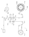
- FIG. 13 is a reference side view showing a process of winding the optical film 6 around the optical film winding core 1.
- FIG. 13 shows an example of producing an optical film roll body 51 by producing a long strip-shaped polarizing film as the optical film 6 and winding the polarizing film (optical film 6) around the winding core 1. There is.
- the system of FIG. 13 has a step A of producing a polarizing film which is the optical film 6, a step B of subjecting the polarizing film to an arbitrary treatment, and a step C of winding the polarizing film (optical film 6).
- the arrow indicates the film transport direction.
- the polarizing film production step A for example, a step of dyeing a polyvinyl alcohol film with a dichroic dye such as iodine to obtain a polarizing film is illustrated. This step is a conventionally known step.
- a long strip of polyvinyl alcohol film 71 is drawn out, and a swelling bath 72, a dyeing bath 73, a crosslinking bath 74, and a washing bath 75 are sequentially drawn while stretching the film. Soak.
- the polarizing film (optical film 6) is obtained.
- the step B of subjecting the polarizing film to any treatment is performed as necessary.
- Examples include a step of laminating a protective film and a step of subjecting the polarizing film to an arbitrary surface treatment.
- a biaxial turret type winding device is illustrated as the step C of winding the polarizing film.
- the two winding shafts are respectively loaded with the above-mentioned optical film winding core 1.
- the end portion of the polarizing film (optical film 6) is connected to the tip end portion 31a of the dummy film 31 of the one winding core 1 via an adhesive portion or the like.
- reference numeral 11 is added to one winding core 1.
- an optical film roll body 51 as shown in FIGS. 6 to 8 is obtained.
- An optical film roll body 52 as shown in FIGS.
- 11 and 12 is obtained by connecting another dummy film 32 to the leading end of the optical film 6 of the obtained optical film roll body 51 and winding the dummy film 32. Be done. After winding a polarizing film of a predetermined length on one winding core 1, the polarizing film is cut. Although not shown in particular, the end of the cut polarizing film is connected to the tip 31a of the dummy film 31 of the other winding core 1 via an adhesive or the like, and similarly, the other winding core 1 is provided with an optical film. Optical film roll bodies 51 and 52 around which 6 is wound are obtained. In the figure, reference numeral 12 is added to the other winding core 1.
- optical film roll body 51 (or the optical film roll body 52) of the present invention
- the optical film 6 is separated from the dummy film 31 of the optical film roll body 51.
- the optical film 6 and another optical film can be joined and conveyed. That is, in the continuous supply method of the present invention, after the optical film 6 is pulled out from the optical film roll body 51 (or the optical film 52) and conveyed, the optical film 6 is separated from the dummy film 31 of the roll body 51, The film 6 and another optical film are joined and conveyed. By joining the two optical films in this manner, the optical films can be continuously supplied.
- FIG. 14 shows a continuous feeding device D for optical films.
- the configuration of the continuous supply device D is similar to the device described in Patent Document 2 (Japanese Patent No. 6390848), so refer to Patent Document 2 for details.
- the device for continuously supplying an optical film using the optical film roll body of the present invention is not limited to the device D, and various conventionally known devices can be used.
- the continuous feeding device D conveys the first transporting device D1 for transporting the optical film 6 to any of various processing machines and the first transporting device D1 for transporting another optical film 6 joined to the preceding optical film 6. And two transport devices D2.
- the optical film 6 is cut into, for example, a desired shape or size by the processing machine.
- the arrow indicates the film transport direction.
- the term is prefixed with “first” and the symbol is suffixed with “ ⁇ 1”.
- the optical film related to the second transport device D2 and the like the term is prefixed with "second”, and the symbol is suffixed with "-2”.
- the first transport device D1 is a unit in which the first optical film roll body is loaded, and a first feeding unit 71-1 for feeding the film, and a first feeding unit 71-1 arranged downstream of the unit 71-1 for fixing the film.
- a first suction means 72-1 and a first fixing member 73-1 and a first transport side suction means 74-1 and a first transport side fixing member which are arranged on the downstream side of the first suction means 72-1 and fix the film. It has 75-1 and a first cutting means 76-1.
- the second transport device D2 is a unit in which the second optical film roll body is loaded, and a second feeding unit 71-2 for feeding the film, and a second feeding unit 71-2 arranged downstream of the unit 71-2 for fixing the film.
- the first optical film roll body loaded in the first feeding unit 71-1 at least the optical film roll body of the present invention is used.
- the second optical film roll body loaded in the second feeding unit 71-2 may not be the optical film roll body of the present invention, but the optical film roll body of the present invention is preferably used.
- an optical film roll body an optical film roll body 51 as shown in FIGS. 6 to 8 having no dummy film is used.
- an optical film roll body an optical film roll body 52 as shown in FIGS. 11 and 12 above
- an optical film roll body to which another dummy film is connected may be used as the first optical film roll body 5-1 or a second optical film roll body 5-2 is separately provided. You may use the optical film roll body which does not have this dummy film.
- the first optical film 6-1 delivered from the first optical film roll body 5-1 is delivered to the processing machine E through the first delivery unit 71-1 of the first delivery device D1 and subjected to various processing. It On the other hand, another second dummy film 32-2 is unrolled from the second optical film roll body 5-2 loaded in the second unrolling unit 71-2 of the second transport device D2, and the other second dummy film is unrolled. 32-2 is wound around the recovery core member 79-2.
- another second dummy film 32-2 is unwound from the second optical film roll body 5-2 and wound around the recovery core member 79-2 of the second dummy film 32-2.
- a sensor (not shown) connects another second dummy film 32-2 and the second optical film 6-2 to a connecting portion d-2 (a rear end portion 32b-2 of another second dummy film 32-2). And a portion where the front end portion 6a-2 of the second optical film 6-2 is connected) is detected. Then, as shown in FIG.
- the second cutting means 76-2 cuts the second optical film 6-2 in the width direction on the upstream side of the connecting portion d-2, and separates the second dummy film 32-2 into the second optical film. Separate from film 6-2. At this time, it is preferable to cut by the second cutting means 76-2 so that the connecting portion d-2 is not included in the second optical film 6-2 after cutting. For example, as shown in FIG.
- cutting is performed at a position separated by a predetermined length W-2 from the end of the connecting portion d-2.
- Examples of the predetermined length W-2 include 10 cm or less.
- the second dummy film 32-2 after cutting is wound around the recovery core member 79-2.
- the end portion of the second optical film 6-2 has the second suction means 72-2 and the second fixing member 73-. In the state of being fixed by 2, it stands by until the joining process described later.
- the first transport device D1 the first optical film 6-1 is transported to the processing machine E.
- the temporary fixing means is released (see the description in FIG. 10), and the first dummy film 31-1 is paid out.
- a sensor (not shown) causes a connecting portion d-1 between the first optical film 6-1 and the first dummy film 31-1. (A portion where the rear end portion 6b-1 of the first optical film 6-1 and the front end portion 31a-1 of the first dummy film 31-1 are connected) is detected. Then, as shown in FIG.
- the first suction means 72-1 and the first fixing member 73-1 sandwich and fix the first dummy film 31-1, and the first transport side suction means 74-
- the first and first transport-side fixing members 75-1 sandwich and fix the first optical film 6-1.
- the first cutting means 76-1 cuts the first optical film 6-1 in the width direction on the downstream side of the connecting portion d-1, and the first optical film 6-1 is cut into the first dummy film 31. Separate from -1. At this time, it is preferable to cut by the first cutting means 76-1 so that the connecting portion d-1 is not included in the cut first optical film 6-1. For example, as shown in FIG. 15A, cutting is performed at a position separated by a predetermined length W-1 from the end of the connecting portion d-1. Examples of the predetermined length W-1 include 10 cm or less.
- the first transport-side suction means 74-1 and the first transport-side fixing member 75-1 that fix the end portion of the separated first optical film 6-1 are It is moved to the end of the second optical film 6-2 in the standby state.
- the second suction means 72-2 and the second fixing member 73-2, which fix the ends of the second optical film 6-2 may be moved to the ends of the first optical film 6-1. , And both may be moved relative to each other.
- the end portion of the first optical film 6-1 and the end portion of the second optical film 6-2 are connected using an adhesive tape 69 or the like.
- the first transport side suction means 74-1 and the first transport side fixing member 75-1 fix the first optical film 6-1 and the second suction means 72-2 and the second fixation.
- the fixation of the second optical film 6-2 by the member 73-2 is released.
- the second optical film 6-2 is sent to the processing machine E after the first optical film 6-1. In this way, the first optical film 6-1 that precedes the second optical film 6-2 that follows can be joined, and the optical film can be continuously supplied to the processing machine E.
- the dummy film 31 is interposed between the core member 2 and the optical film 6. Therefore, the dummy film 31 can be formed from the core member 2 to the portion where the two optical films (the first optical film that precedes the second optical film and the second optical film that follow) are joined. That is, as shown in FIG. 16, the preceding first optical film 6-1 can be transported to the location Y where the two films are joined by the first dummy film 31-1. Therefore, the two optical films can be joined without wasting the optical film.
- the first dummy film 31-1 may be discarded, but preferably, it can be reused by rewinding it around the core member 2 and temporarily fixing the tip end portion by the temporary fixing means.
- the optical film core 1 can be regenerated.
- a general-purpose synthetic resin film such as a polyethylene terephthalate film may be used as the dummy film, and therefore it is cheaper than the optical film. Therefore, when the optical film roll body of the present invention is used, the manufacturing cost can be reduced as compared with the conventional case where the end material of the optical film is discarded.
- the second optical film 6-2 from the location Y to the collecting core member 79-2 is wound as the end material on the collecting core member 79-2 and discarded.
- the optical film roll body 52 to which another dummy film 32 is connected as shown in FIGS. 14 and 16
- the second dummy film 32-2 can convey the second optical film 6-2 to the position Y where the two films are joined. Therefore, the two optical films can be joined without wasting the optical film.
Landscapes
- Physics & Mathematics (AREA)
- General Physics & Mathematics (AREA)
- Optics & Photonics (AREA)
- Replacement Of Web Rolls (AREA)
- Polarising Elements (AREA)
- Storage Of Web-Like Or Filamentary Materials (AREA)
Abstract
光学フィルム用巻き芯1は、芯部材2と、前記芯部材2に巻き付けられたダミーフィルム31であって、光学フィルムが連結され得る先端部31aを有するダミーフィルム31と、を有する。前記巻き芯のダミーフィルム31に光学フィルムを連結することにより、光学フィルムを無駄にすることなく、前記光学フィルムともう1つの光学フィルムを接合できる。
Description
本発明は、光学フィルムを巻き付けるために用いられる巻き芯及びその巻き芯に光学フィルムが巻き付けられているロール体などに関する。
従来、光学フィルムは、液晶表示装置や有機表示装置などのディスプレイなどに使用されている。光学フィルムとしては、例えば、偏光フィルム、偏光フィルムを含む偏光板、位相差フィルム、アンチグレアフィルムなどが挙げられる。
光学フィルムは、通常、長尺帯状である。この長尺帯状の光学フィルムは加工機にて加工されて使用される。
加工の際に、先行する光学フィルムに続けて新たな光学フィルムを加工機に供給するために、先行する光学フィルムの後端部に、新たな光学フィルムの先端部を接合することが行われている。このような接合は、スプライス処理とも呼ばれる。
2つの光学フィルムの端部を接合する方法として、粘着テープ貼り或いは熱溶着などが知られている(特許文献1)。
光学フィルムは、通常、長尺帯状である。この長尺帯状の光学フィルムは加工機にて加工されて使用される。
加工の際に、先行する光学フィルムに続けて新たな光学フィルムを加工機に供給するために、先行する光学フィルムの後端部に、新たな光学フィルムの先端部を接合することが行われている。このような接合は、スプライス処理とも呼ばれる。
2つの光学フィルムの端部を接合する方法として、粘着テープ貼り或いは熱溶着などが知られている(特許文献1)。
また、特許文献2には、先行する光学フィルムと新たな光学フィルムを接合することにより、光学フィルムを連続的に供給する連続供給装置が開示されている。
具体的には、特許文献2の図7を参照して、第1ロールから引き出された第1光学フィルムを、第1吸着手段103及び第1固定部材102、並びに、搬送側吸着手段303及び搬送側固定部材302にて吸着固定する。2つの固定部材の間の第1光学フィルムを、第1切断手段101にて切断する。他方、第2ロールから引き出された第2光学フィルムの先端部を、第2吸着手段203及び第2固定部材202にて固定する。搬送側吸着手段303及び搬送側固定部材302で固定された第1光学フィルムの後端部を、前記第2吸着手段203及び第2固定部材202にて固定された第2光学フィルムの先端部に移動させた後、第1光学フィルムの後端部と第2光学フィルムの先端部をテープにて接合する。
特許文献2の連続供給装置は、前記のようにして2つの光学フィルムを接合し、光学フィルムを連続的に供給できる装置である。
具体的には、特許文献2の図7を参照して、第1ロールから引き出された第1光学フィルムを、第1吸着手段103及び第1固定部材102、並びに、搬送側吸着手段303及び搬送側固定部材302にて吸着固定する。2つの固定部材の間の第1光学フィルムを、第1切断手段101にて切断する。他方、第2ロールから引き出された第2光学フィルムの先端部を、第2吸着手段203及び第2固定部材202にて固定する。搬送側吸着手段303及び搬送側固定部材302で固定された第1光学フィルムの後端部を、前記第2吸着手段203及び第2固定部材202にて固定された第2光学フィルムの先端部に移動させた後、第1光学フィルムの後端部と第2光学フィルムの先端部をテープにて接合する。
特許文献2の連続供給装置は、前記のようにして2つの光学フィルムを接合し、光学フィルムを連続的に供給できる装置である。
前記連続供給装置において、第1光学フィルムのうち、第2光学フィルムに接合されなかった端材が残存する。この端材は、第1光学フィルムのうち、第1ロールに固定された箇所から第1吸着手段103及び第1固定部材102にて固定された箇所までである。この端材は、引用文献1の[0059]の欄では、最少程度残量と記載されている。
かかる端材は、2つの光学フィルムを接合後に廃棄される。しかし、コスト面及び資源の有効利用の観点から、光学フィルムをできるだけ余すこと無く利用することが求められている。
かかる端材は、2つの光学フィルムを接合後に廃棄される。しかし、コスト面及び資源の有効利用の観点から、光学フィルムをできるだけ余すこと無く利用することが求められている。
本発明の目的は、光学フィルムを無駄にすることなく接合できる、光学フィルム用巻き芯、光学フィルムロール体及び光学フィルムの連続供給方法を提供することである。
本発明の光学フィルム用巻き芯は、芯部材と、前記芯部材に巻き付けられたダミーフィルムであって、光学フィルムが連結され得る先端部を有するダミーフィルムと、を有する。
本発明の好ましい光学フィルム用巻き芯は、前記ダミーフィルムの先端部が、展開防止のために仮止めされている。
本発明の好ましい光学フィルム用巻き芯は、前記ダミーフィルムが前記芯部材に1周以上巻き付けられることによって、前記芯部材の周囲にダミーフィルム層が形成されており、前記ダミーフィルムの先端部と前記ダミーフィルム層の表面に跨がって、仮止めテープが貼り付けられており、前記仮止めテープには、前記ダミーフィルムの先端部の縁又はその近傍に沿って、切断補助線が形成されている。
本発明の好ましい光学フィルム用巻き芯は、前記ダミーフィルムが前記芯部材に1周以上巻き付けられることによって、前記芯部材の周囲にダミーフィルム層が形成されており、前記ダミーフィルムの先端部と前記ダミーフィルム層の表面に跨がって、仮止めテープが貼り付けられており、前記仮止めテープには、前記ダミーフィルムの先端部の縁又はその近傍に沿って、切断補助線が形成されている。
本発明の別の局面によれば、光学フィルムロール体を提供する。
本発明の光学フィルムロール体は、上記いずれかの光学フィルム用巻き芯と、前記巻き芯に巻き付けられた光学フィルムと、を有し、前記光学フィルムの後端部と前記ダミーフィルムの先端部が連結された状態で、前記光学フィルムが前記巻き芯に巻き付けられている。好ましい光学フィルムロール体は、光学フィルムの先端部に、別のダミーフィルムが連結されている。
本発明の光学フィルムロール体は、上記いずれかの光学フィルム用巻き芯と、前記巻き芯に巻き付けられた光学フィルムと、を有し、前記光学フィルムの後端部と前記ダミーフィルムの先端部が連結された状態で、前記光学フィルムが前記巻き芯に巻き付けられている。好ましい光学フィルムロール体は、光学フィルムの先端部に、別のダミーフィルムが連結されている。
本発明の別の局面によれば、光学フィルムの連続供給方法を提供する。
本発明の光学フィルムの連続供給方法は、上記いずれかの光学フィルムロール体から光学フィルムを引き出した後、前記ダミーフィルムから前記光学フィルムを分離し、この光学フィルムと別の光学フィルムを接合して搬送する。
本発明の光学フィルムの連続供給方法は、上記いずれかの光学フィルムロール体から光学フィルムを引き出した後、前記ダミーフィルムから前記光学フィルムを分離し、この光学フィルムと別の光学フィルムを接合して搬送する。
本発明の光学フィルム用巻き芯に光学フィルムを巻き付けることにより、光学フィルムを無駄にすることなく2つの光学フィルムを接合できる。
また、本発明の光学フィルムロール体を用いることにより、光学フィルムを無駄にすることなく2つの光学フィルムを接合できる。
また、本発明の光学フィルムロール体を用いることにより、光学フィルムを無駄にすることなく2つの光学フィルムを接合できる。
本明細書において、後端部は、フィルムの端部のうち芯部材に近い側の端部を指し、先端部は、前記後端部とは反対側の端部(芯部材から離れた側の端部)を指す。用語の頭に、「第1」、「第2」を付す場合があるが、この第1などは、用語を区別するためだけに付加されたものであり、その順序や優劣などの特別な意味を持たない。また、「下限値XXX~上限値YYY」で表される数値範囲は、下限値XXX以上上限値YYY以下を意味する。前記数値範囲が別個に複数記載されている場合、任意の下限値と任意の上限値を選択し、「任意の下限値~任意の上限値」を設定できるものとする。
[光学フィルム用巻き芯]
図1は、本発明の光学フィルム用巻き芯1の斜視図であり、図2は、その正面図であり、図3は、その側面図であり、図4は、IV-IV線で切断し且つ拡大した断面図である。
本発明の光学フィルム用巻き芯1は、後述するように、その周囲に光学フィルムが巻き付けられて使用される。
図1乃至図4を参照して、光学フィルム用巻き芯1は、芯部材2と、前記芯部材2に巻き付けられたダミーフィルム31であって、光学フィルムが連結され得る先端部31aを有するダミーフィルム31と、を有する。必要に応じて、前記巻き付けられたダミーフィルム31が芯部材2から展開することを防止するために、ダミーフィルム31の先端部に仮止め手段が具備されている。
図1は、本発明の光学フィルム用巻き芯1の斜視図であり、図2は、その正面図であり、図3は、その側面図であり、図4は、IV-IV線で切断し且つ拡大した断面図である。
本発明の光学フィルム用巻き芯1は、後述するように、その周囲に光学フィルムが巻き付けられて使用される。
図1乃至図4を参照して、光学フィルム用巻き芯1は、芯部材2と、前記芯部材2に巻き付けられたダミーフィルム31であって、光学フィルムが連結され得る先端部31aを有するダミーフィルム31と、を有する。必要に応じて、前記巻き付けられたダミーフィルム31が芯部材2から展開することを防止するために、ダミーフィルム31の先端部に仮止め手段が具備されている。
芯部材2は、ダミーフィルム31を巻き付ける部材である。芯部材2は、その周囲にダミーフィルム31を巻き付けることができるように構成されていれば、特に限定されない。
芯部材2は、例えば、支持軸21と、ダミーフィルム31を巻き付ける外筒部23と、を有する。必要に応じて、前記支持軸21と外筒部23の間に、中間筒部22が介在されていてもよい。
芯部材2は、例えば、支持軸21と、ダミーフィルム31を巻き付ける外筒部23と、を有する。必要に応じて、前記支持軸21と外筒部23の間に、中間筒部22が介在されていてもよい。
支持軸21は、例えば、鉄やステンレスなどの金属製の円形シャフトから構成されている。
中間筒部22は、支持軸21の周囲に設けられている。中間筒部22は、支持軸21に対して固定的に設けられていてもよく、或いは、支持軸21に対して回転可能に設けられていてもよい。例えば、中間筒部22は、支持軸21に固定されている。中間筒部22の外形状は、通常、図示のように円筒状であるが、四角筒状などであってもよい(図示せず)。
中間筒部22は、支持軸21の周囲に設けられている。中間筒部22は、支持軸21に対して固定的に設けられていてもよく、或いは、支持軸21に対して回転可能に設けられていてもよい。例えば、中間筒部22は、支持軸21に固定されている。中間筒部22の外形状は、通常、図示のように円筒状であるが、四角筒状などであってもよい(図示せず)。
外筒部23は、中間筒部22よりも大径な筒状であり、中間筒部22の周囲に設けられている。外筒部23は、中間筒部22に対して固定的に設けられていてもよく、或いは、中間筒部22に対して回転可能に設けられていてもよい。例えば、外筒部23は、中間筒部22に固定されている。外筒部23の外形状は、通常、図示のように円筒状であるが、四角筒状などであってもよい(図示せず)。外筒部23は、金属、合成樹脂、ゴムなどで形成される。
外筒部23の大きさは、特に限定されず、適宜設定できる。例えば、外筒部23の幅は、50cm~6m、好ましくは80cm~4mである。なお、幅は、軸芯方向長さをいう。例えば、外筒部23の直径は、2cm~1mであり、好ましくは3cm~60cmである。
外筒部23の大きさは、特に限定されず、適宜設定できる。例えば、外筒部23の幅は、50cm~6m、好ましくは80cm~4mである。なお、幅は、軸芯方向長さをいう。例えば、外筒部23の直径は、2cm~1mであり、好ましくは3cm~60cmである。
ダミーフィルム31は、光学フィルム以外のフィルムである。ダミーフィルム31は、前記芯部材2に巻き付けることができる柔軟性を有し、且つ、加工機などによって引張られても容易に破断しない程度の機械的強度を有するフィルムが用いられる。
ダミーフィルム31としては、従来公知の合成樹脂フィルム、紙、合成紙、不織布などを用いることができる。例えば、ダミーフィルム31として、ポリエステル系、ポリオレフィン系、ポリスチレン系などの汎用的な合成樹脂フィルムを用いることができる。
前記柔軟性及び機械的強度を有している限り、ダミーフィルム31の厚みも特に限定されない。
ダミーフィルム31としては、従来公知の合成樹脂フィルム、紙、合成紙、不織布などを用いることができる。例えば、ダミーフィルム31として、ポリエステル系、ポリオレフィン系、ポリスチレン系などの汎用的な合成樹脂フィルムを用いることができる。
前記柔軟性及び機械的強度を有している限り、ダミーフィルム31の厚みも特に限定されない。
ダミーフィルム31は、芯部材2に巻き付けられている。
具体的には、ダミーフィルム31の後端部31bは、芯部材2の外筒部23の表面に固定されている。ダミーフィルム31の後端部31bは、外筒部23(芯部材2)に着脱可能な状態で固定されているが、着脱不能又は困難な状態で固定されていてもよい。ダミーフィルム31の後端部31bの固定方法としては、テープ止め、クリップ止め、溝への係止などが挙げられる。
具体的には、ダミーフィルム31の後端部31bは、芯部材2の外筒部23の表面に固定されている。ダミーフィルム31の後端部31bは、外筒部23(芯部材2)に着脱可能な状態で固定されているが、着脱不能又は困難な状態で固定されていてもよい。ダミーフィルム31の後端部31bの固定方法としては、テープ止め、クリップ止め、溝への係止などが挙げられる。
後端部31bが外筒部23に固定されたダミーフィルム31は、外筒部23(芯部材2)の周囲に巻き付けられている。ダミーフィルム31は、通常、1周以上巻き付けられ、好ましくは、2周以上巻き付けられる。なお、図3及び図4では、ダミーフィルム31が外筒部23(芯部材2)の周囲に1.5周巻き付けられた場合を図示しているが、これは、あくまで便宜上であり、ダミーフィルム31の巻き数は、図示例に限定されるわけでない(他の側面図及び断面図も同様)。
ダミーフィルム31が1周以上巻き付けられることによって、前記外筒部23(芯部材2)の周囲にダミーフィルム層が形成される。
ダミーフィルム31が1周以上巻き付けられることによって、前記外筒部23(芯部材2)の周囲にダミーフィルム層が形成される。
巻き付けられたダミーフィルム31が展開することを防止するため、ダミーフィルム31の先端部31aは、仮止めされている。例えば、ダミーフィルム31の先端部31aは、仮止め手段によってダミーフィルム層の表面に仮止めされている。
仮止め手段は、通常の状態ではダミーフィルム31が巻き戻りしないように、その先端部をダミーフィルム層の表面に止着し、一方、剥離力が作用する状態では前記止着を解除してダミーフィルム31を展開できるようにするものである。剥離力が作用する状態としては、ダミーフィルム31の先端部31aが外側に引っ張られる場合などが挙げられる。
仮止め手段としては、例えば、図示例のような仮止めテープ4を用いた止着、その他図示しないが擬似接着などが挙げられる。
仮止め手段は、通常の状態ではダミーフィルム31が巻き戻りしないように、その先端部をダミーフィルム層の表面に止着し、一方、剥離力が作用する状態では前記止着を解除してダミーフィルム31を展開できるようにするものである。剥離力が作用する状態としては、ダミーフィルム31の先端部31aが外側に引っ張られる場合などが挙げられる。
仮止め手段としては、例えば、図示例のような仮止めテープ4を用いた止着、その他図示しないが擬似接着などが挙げられる。
前記擬似接着は、ダミーフィルム31の先端部31aの裏面をダミーフィルム層の表面に弱い接着力で接着することである。前記弱い接着力は、通常の状態では剥がれず、且つ、剥離力が作用する状態で剥がれる程度の接着力をいう。
擬似接着としては、例えば、ダミーフィルム31の先端部31aの裏面をダミーフィルム層の表面に静電シールすること、或いは、ダミーフィルム31の先端部31aの裏面をダミーフィルム層の表面に接着力が非常に弱い接着剤で接着すること、などが挙げられる。
擬似接着としては、例えば、ダミーフィルム31の先端部31aの裏面をダミーフィルム層の表面に静電シールすること、或いは、ダミーフィルム31の先端部31aの裏面をダミーフィルム層の表面に接着力が非常に弱い接着剤で接着すること、などが挙げられる。
仮止め手段としては、図示例のように仮止めテープ4を用いた止着が好ましい。
この仮止めテープ4は、図1、図2及び図4に示すように、基材41と基材41の裏面に設けられた粘着剤層42とを有するテープ本体と、前記テープ本体の面内に形成された切断補助線43と、を有する。
前記基材41は、特に限定されず、合成樹脂フィルム、紙、合成紙、発泡樹脂シートなどの従来公知のウェブを用いることができる。前記粘着剤層42を構成する粘着剤は、特に限定されず、例えば、感圧型粘着剤、感熱粘着剤などが挙げられる。
切断補助線43は、その線に沿ってテープ本体を容易に分断できるようにするためにテープ本体に形成された処理線をいう。切断補助線43としては、図示の示すようなミシン目431の他、切り目、ハーフカット線などが挙げられる。
切断補助線43は、直線状に延びて形成されていることが好ましい。
この仮止めテープ4は、図1、図2及び図4に示すように、基材41と基材41の裏面に設けられた粘着剤層42とを有するテープ本体と、前記テープ本体の面内に形成された切断補助線43と、を有する。
前記基材41は、特に限定されず、合成樹脂フィルム、紙、合成紙、発泡樹脂シートなどの従来公知のウェブを用いることができる。前記粘着剤層42を構成する粘着剤は、特に限定されず、例えば、感圧型粘着剤、感熱粘着剤などが挙げられる。
切断補助線43は、その線に沿ってテープ本体を容易に分断できるようにするためにテープ本体に形成された処理線をいう。切断補助線43としては、図示の示すようなミシン目431の他、切り目、ハーフカット線などが挙げられる。
切断補助線43は、直線状に延びて形成されていることが好ましい。
前記仮止めテープ4は、ダミーフィルム31の先端部31aの表面と、ダミーフィルム層の表面と、に跨がって貼り付けられている。好ましくは、切断補助線43がダミーフィルム31の先端部31aの縁31c又はその近傍に位置するように、仮止めテープ4が貼り付けられている。換言すると、ダミーフィルム31の先端部31aとダミーフィルム層の表面に跨がって貼り付けられた仮止めテープ4には、ダミーフィルム31の先端部31aの縁31c又はその近傍に沿って、切断補助線43が形成されている。従って、仮止めテープ4は、切断補助線43を基準にして区画すると、ダミーフィルム31の先端部31aの表面に貼り付けられた先領域46と、ダミーフィルム層の表面に貼り付けられた後領域45と、を有する。
前記近傍(先端部31aの縁31cの近傍)は、ダミーフィルム31の先端部31aの縁31cの付近を意味する。前記近傍は、例えば、前記先端部31aの縁31cから5mm以内の範囲を含み、好ましくは3mm以内の範囲を含む。
先端部31aが仮止めされたダミーフィルム31を有する光学フィルム用巻き芯1は、ダミーフィルム31が展開することなく、保管・運搬に供することができる。
前記近傍(先端部31aの縁31cの近傍)は、ダミーフィルム31の先端部31aの縁31cの付近を意味する。前記近傍は、例えば、前記先端部31aの縁31cから5mm以内の範囲を含み、好ましくは3mm以内の範囲を含む。
先端部31aが仮止めされたダミーフィルム31を有する光学フィルム用巻き芯1は、ダミーフィルム31が展開することなく、保管・運搬に供することができる。
図5は、他の実施形態の光学フィルム用巻き芯1を示す。
この光学フィルム用巻き芯1は、切断用補助線43として切り目432が採用されている点において上記実施形態と異なっている。
図5を参照して、切り目432は、仮止めテープ4の基材を2分する切断線である。切り目432は、例えば、ダミーフィルム31の先端部31aの縁31c又はその近傍に位置するように、仮止めテープ4の面内に形成されている。好ましくは、切り目432は、仮止めテープ4の両側縁41e,41fに至らないように、仮止めテープ4の面内に形成されている。従って、切り目432の両端と仮止めテープ4の両側縁41e,41fの間には、不切り部411,412が存在する。
切断用補助線43として切り目432が形成された仮止めテープ4を有する光学フィルム用巻き芯1も、ミシン目431を採用した場合と同様に、ダミーフィルム31が巻き戻りせず、一方、剥離力が作用する状態では前記不切り部411,412が切断されてダミーフィルム31を展開できるようになる。
この光学フィルム用巻き芯1は、切断用補助線43として切り目432が採用されている点において上記実施形態と異なっている。
図5を参照して、切り目432は、仮止めテープ4の基材を2分する切断線である。切り目432は、例えば、ダミーフィルム31の先端部31aの縁31c又はその近傍に位置するように、仮止めテープ4の面内に形成されている。好ましくは、切り目432は、仮止めテープ4の両側縁41e,41fに至らないように、仮止めテープ4の面内に形成されている。従って、切り目432の両端と仮止めテープ4の両側縁41e,41fの間には、不切り部411,412が存在する。
切断用補助線43として切り目432が形成された仮止めテープ4を有する光学フィルム用巻き芯1も、ミシン目431を採用した場合と同様に、ダミーフィルム31が巻き戻りせず、一方、剥離力が作用する状態では前記不切り部411,412が切断されてダミーフィルム31を展開できるようになる。
[光学フィルムロール体]
図6は、本発明の光学フィルムロール体51の正面図、図7は、その側面図であり、図8は、VIII-VIII線で切断し且つ拡大した断面図である。図9は、巻き芯1のダミーフィルム31の先端部31aに光学フィルム6の後端部6bを連結する過程を示す斜視図である。ただし、図9では、光学フィルム6の一部分を省略し且つ光学フィルム6を二点鎖線で表し、接着部65に無数のドットを付している。
図6は、本発明の光学フィルムロール体51の正面図、図7は、その側面図であり、図8は、VIII-VIII線で切断し且つ拡大した断面図である。図9は、巻き芯1のダミーフィルム31の先端部31aに光学フィルム6の後端部6bを連結する過程を示す斜視図である。ただし、図9では、光学フィルム6の一部分を省略し且つ光学フィルム6を二点鎖線で表し、接着部65に無数のドットを付している。
図6乃至図8を参照して、本発明の光学フィルムロール体51は、上述した光学フィルム用巻き芯1と、この巻き芯1に巻き付けられた光学フィルム6と、を有する。前記光学フィルム6は、光学フィルム6の後端部6bと巻き芯1のダミーフィルム31の先端部31aが連結された状態で、巻き芯1の周囲に巻き付けられている。光学フィルム6の後端部6bと巻き芯1のダミーフィルム31の先端部31aの連結方法は、特に限定されず、後述する接着部を用いた接着、その他図示しないが、粘着テープ止め、レーザー接合などが挙げられる。光学フィルム6は、長尺帯状である。長尺帯状は、長さ方向の長さが、幅方向の長さに比して十分に大きい長方形状をいう。
具体的には、図6及び図9に示すように、前記巻き芯1のダミーフィルム31の先端部31aの表面に、接着部65が設けられている。接着部65は、ダミーフィルム31の先端部31aと光学フィルム6の後端部6bの間に介在し、両部31a,6bを連結する。接着部65としては、両面粘着テープ(基材の両面に粘着剤層が設けられたテープ)、粘着剤層、接着剤層などが挙げられる。接着部65は、フィルムの幅方向略全体に亘って帯状に設けられている。なお、ダミーフィルム31の先端部31aと光学フィルム6の後端部6bが容易に剥がれないことを条件として、前記接着部65は、フィルムの幅方向において部分的に又は断続的に設けられていてもよい。
図9を参照して、前記ダミーフィルム31の先端部31aに接着部65を設けた後、この接着部65に光学フィルム6の後端部6bの裏面を接着する。このようにして光学フィルム6の後端部6bを巻き芯1に固定する。後端部6bをダミーフィルム31の先端部31aに連結した後、長尺帯状の光学フィルム6をダミーフィルム層(巻き芯1)の周囲に巻き付けていく。つまり、光学フィルム6をダミーフィルム31の巻き方向と同じ方向に巻き付けていく。
このようにして図6乃至図8に示す光学フィルムロール体51が得られる。
図9を参照して、前記ダミーフィルム31の先端部31aに接着部65を設けた後、この接着部65に光学フィルム6の後端部6bの裏面を接着する。このようにして光学フィルム6の後端部6bを巻き芯1に固定する。後端部6bをダミーフィルム31の先端部31aに連結した後、長尺帯状の光学フィルム6をダミーフィルム層(巻き芯1)の周囲に巻き付けていく。つまり、光学フィルム6をダミーフィルム31の巻き方向と同じ方向に巻き付けていく。
このようにして図6乃至図8に示す光学フィルムロール体51が得られる。
図6乃至図8を参照して、長尺帯状の光学フィルム6は、後端部6bがダミーフィルム31の先端部31aに連結された状態で、ダミーフィルム層(巻き芯1)の周囲に巻かれている。光学フィルム6の巻き数は、特に限定されず、適宜設定される。なお、図7及び図8では、複数回巻かれた光学フィルム6について、その内側の1.5周及び外側の1.5周のみを表し、光学フィルム6の中間巻き部分Xの図示を省略している(他の側面図及び断面図も同様)。
巻き芯1に巻かれた光学フィルム6の先端部6aの展開を防止するため、必要に応じて、光学フィルム6の先端部6aを仮止めしてもよい(この先端部6aの仮止めは図示せず)。
巻き芯1に巻かれた光学フィルム6の先端部6aの展開を防止するため、必要に応じて、光学フィルム6の先端部6aを仮止めしてもよい(この先端部6aの仮止めは図示せず)。
上記巻き芯1にあっては、ダミーフィルム31の先端部31aが仮止め手段によって仮止めされている。前記光学フィルムロール体51から光学フィルム6を引き出していくと、ダミーフィルム31の先端部31aが光学フィルム6の後端部6bに引っ張られる。ダミーフィルム31の先端部31aが外側に引っ張られることによって、仮止め手段が解除され、光学フィルム6の引き出しに追従してダミーフィルム31が引き出されていくようになる。例えば、仮止め手段として仮止めテープ4が用いられている場合には、図10に示すように、仮止めテープ4が切断補助線43にて容易に破断し、ダミーフィルム31が引き出されていくようになる。なお、図10では、光学フィルム6の一部分を省略し且つ光学フィルム6を二点鎖線で表している。
光学フィルム6としては、従来公知のものを使用できる。
具体的には、液晶表示装置や有機表示装置などのディスプレイに使用される光学フィルム6としては、偏光フィルム、偏光フィルムを含む偏光板、位相差フィルム、アンチグレアフィルム、輝度向上フィルム、視野角向上フィルム、透明導電性フィルムなどが挙げられる。
本発明の光学フィルム6は、前述のディスプレイに使用されるものに限定されず、ディスプレイ以外の用途に使用するものでもよい。ディスプレイ以外の用途としては、光学機器、建築物、医療・食品分野などが挙げられる。光学機器に使用される光学フィルム6としては、例えば、偏光レンズ、透明電波遮断フィルムなどが挙げられる。電子デバイスに使用される光学フィルム6としては、調光窓用フィルムなどが挙げられる。医療・食品分野に使用される光学フィルム6としては、光劣化防止フィルムなどが挙げられる。
特に、ディスプレイに使用される光学フィルム6を、本発明の巻き芯1に巻き付けることが好ましい。
具体的には、液晶表示装置や有機表示装置などのディスプレイに使用される光学フィルム6としては、偏光フィルム、偏光フィルムを含む偏光板、位相差フィルム、アンチグレアフィルム、輝度向上フィルム、視野角向上フィルム、透明導電性フィルムなどが挙げられる。
本発明の光学フィルム6は、前述のディスプレイに使用されるものに限定されず、ディスプレイ以外の用途に使用するものでもよい。ディスプレイ以外の用途としては、光学機器、建築物、医療・食品分野などが挙げられる。光学機器に使用される光学フィルム6としては、例えば、偏光レンズ、透明電波遮断フィルムなどが挙げられる。電子デバイスに使用される光学フィルム6としては、調光窓用フィルムなどが挙げられる。医療・食品分野に使用される光学フィルム6としては、光劣化防止フィルムなどが挙げられる。
特に、ディスプレイに使用される光学フィルム6を、本発明の巻き芯1に巻き付けることが好ましい。
さらに、図11及び図12に示すように、前記巻き芯1に巻き付けられた光学フィルム6の先端部6aに、別のダミーフィルム32が連結されていてもよい。
図11は、他の実施形態に係る光学フィルムロール体52の左側面図であり、図12は、同光学フィルムロール体52の拡大断面図である。なお、図12は、他の実施形態に係る光学フィルムロール体52を、図6のVIII-VIII線と同様の箇所で切断し且つ拡大した断面図である。
図11は、他の実施形態に係る光学フィルムロール体52の左側面図であり、図12は、同光学フィルムロール体52の拡大断面図である。なお、図12は、他の実施形態に係る光学フィルムロール体52を、図6のVIII-VIII線と同様の箇所で切断し且つ拡大した断面図である。
図11及び図12を参照して、この光学フィルムロール体52は、上述した光学フィルム用巻き芯1と、この巻き芯1に巻き付けられた光学フィルム6と、この光学フィルム6の先端部6aに連結された別のダミーフィルム32と、を有する。
別のダミーフィルム32は、その後端部が光学フィルム6の先端部6aに連結された状態で、その光学フィルム層の周囲に巻き付けられている。別のダミーフィルム32は、通常、1周以上巻き付けられ、好ましくは、2周以上巻き付けられる。なお、図11及び図12では、別のダミーフィルム32が光学フィルム層の周囲に1.5周巻き付けられた場合を図示しているが、これは、あくまで便宜上であり、別のダミーフィルム32の巻き数は、図示例に限定されるわけでない。
別のダミーフィルム32は、その後端部が光学フィルム6の先端部6aに連結された状態で、その光学フィルム層の周囲に巻き付けられている。別のダミーフィルム32は、通常、1周以上巻き付けられ、好ましくは、2周以上巻き付けられる。なお、図11及び図12では、別のダミーフィルム32が光学フィルム層の周囲に1.5周巻き付けられた場合を図示しているが、これは、あくまで便宜上であり、別のダミーフィルム32の巻き数は、図示例に限定されるわけでない。
光学フィルム6の先端部6aと別のダミーフィルム32の後端部32bの連結方法は、特に限定されず、図示のような粘着テープ止め、その他図示しないが、上述の接着部65を用いた接着、レーザー接合などが挙げられる。
図11及び図12を参照して、前記光学フィルムロール体52は、光学フィルム6の先端部6aと別のダミーフィルム32の後端部32bが粘着テープ67を介して連結されている。粘着テープ67は、光学フィルム6の先端部6aの表面(又は裏面)と別のダミーフィルム32の後端部32bの表面(又は裏面)に跨がって貼り付けられている。
図示例では、光学フィルム6の先端部6aの縁と別のダミーフィルム32の後端部32bの縁が突き合わされた状態で粘着テープ67にて連結されている。なお、特に図示しないが、光学フィルム6の先端部6aと別のダミーフィルム32の後端部32bを重ね合わせた状態で粘着テープ67にて連結してもよい。
図11及び図12を参照して、前記光学フィルムロール体52は、光学フィルム6の先端部6aと別のダミーフィルム32の後端部32bが粘着テープ67を介して連結されている。粘着テープ67は、光学フィルム6の先端部6aの表面(又は裏面)と別のダミーフィルム32の後端部32bの表面(又は裏面)に跨がって貼り付けられている。
図示例では、光学フィルム6の先端部6aの縁と別のダミーフィルム32の後端部32bの縁が突き合わされた状態で粘着テープ67にて連結されている。なお、特に図示しないが、光学フィルム6の先端部6aと別のダミーフィルム32の後端部32bを重ね合わせた状態で粘着テープ67にて連結してもよい。
芯部材2の周囲に巻き付けられたダミーフィルム31と別のダミーフィルム32とは、材質が同じでもよく或いは異なる材質であってもよい。芯部材2の周囲に巻き付けられたダミーフィルム31と別のダミーフィルム32とは、同形同大であっても或いは異形異大であってもよい。異形異大の場合としては、何れか一方のダミーフィルムが他方のダミーフィルムよりも幅が大きい場合、及び/又は、長さが大きい場合などが挙げられる。
この実施形態の光学フィルムロール体52は、光学フィルム6の後端部6bと芯部材2の間にダミーフィルム31が介在され、光学フィルム6の先端部6aに別のダミーフィルム32が連結されている。このため、かかる光学フィルムロール体52は、後述するように、光学フィルム6の後端部側だけでなく先端部側においても光学フィルム6を無駄にすることなく利用できる。
この実施形態の光学フィルムロール体52は、光学フィルム6の後端部6bと芯部材2の間にダミーフィルム31が介在され、光学フィルム6の先端部6aに別のダミーフィルム32が連結されている。このため、かかる光学フィルムロール体52は、後述するように、光学フィルム6の後端部側だけでなく先端部側においても光学フィルム6を無駄にすることなく利用できる。
[光学フィルム用巻き芯の使用例]
図13は、上記光学フィルム用巻き芯1に光学フィルム6を巻き付けていく過程を示す参考側面図である。
図13では、光学フィルム6として長尺帯状の偏光フィルムを作製し、その偏光フィルム(光学フィルム6)を巻き芯1に巻き取っていくことによって、光学フィルムロール体51を作製する一例を示している。
図13は、上記光学フィルム用巻き芯1に光学フィルム6を巻き付けていく過程を示す参考側面図である。
図13では、光学フィルム6として長尺帯状の偏光フィルムを作製し、その偏光フィルム(光学フィルム6)を巻き芯1に巻き取っていくことによって、光学フィルムロール体51を作製する一例を示している。
図13のシステムは、光学フィルム6である偏光フィルムを作製する工程Aと、偏光フィルムに任意の処理を施す工程Bと、偏光フィルム(光学フィルム6)を巻き取る工程Cと、を有する。図中、矢印はフィルムの搬送方向を示す。
図示例では、偏光フィルム作製工程Aとして、例えば、ポリビニルアルコール系フィルムをヨウ素などの二色性色素で染色して偏光フィルムを得る工程を例示している。かかる工程は、従来公知のものであり、簡単に説明すると、長尺帯状のポリビニルアルコール系フィルム71を引き出し、それを延伸しながら膨潤浴72、染色浴73、架橋浴74、洗浄浴75に順に浸漬する。このようにして、偏光フィルム(光学フィルム6)が得られる。
偏光フィルムに任意の処理を施す工程Bは、必要に応じて行われる。例えば、前記工程Bとしては、前記偏光フィルムに保護フィルムなどを貼り合せる工程、保護フィルムが貼り合された偏光フィルムに反対面(前記保護フィルムが貼り合わされた面とは反対側の面)に表面保護フィルムを貼り合せる工程、前記偏光フィルムに任意の表面処理を施す工程などが挙げられる。
図示例では、偏光フィルム作製工程Aとして、例えば、ポリビニルアルコール系フィルムをヨウ素などの二色性色素で染色して偏光フィルムを得る工程を例示している。かかる工程は、従来公知のものであり、簡単に説明すると、長尺帯状のポリビニルアルコール系フィルム71を引き出し、それを延伸しながら膨潤浴72、染色浴73、架橋浴74、洗浄浴75に順に浸漬する。このようにして、偏光フィルム(光学フィルム6)が得られる。
偏光フィルムに任意の処理を施す工程Bは、必要に応じて行われる。例えば、前記工程Bとしては、前記偏光フィルムに保護フィルムなどを貼り合せる工程、保護フィルムが貼り合された偏光フィルムに反対面(前記保護フィルムが貼り合わされた面とは反対側の面)に表面保護フィルムを貼り合せる工程、前記偏光フィルムに任意の表面処理を施す工程などが挙げられる。
図示例では、偏光フィルムを巻き取る工程Cとして、二軸ターレット式巻取り装置を例示している。この2つの巻取り軸に、それぞれ上述の光学フィルム用巻き芯1が装填されている。
前記偏光フィルム(光学フィルム6)の端部を、一方の巻き芯1のダミーフィルム31の先端部31aに接着部などを介して連結する。図中、一方の巻き芯1に符号11を付加している。
そして、巻き芯1を回転させて偏光フィルム(光学フィルム6)を巻き取っていくことにより、図6乃至図8に示すような光学フィルムロール体51が得られる。なお、得られた光学フィルムロール体51の光学フィルム6の先端部に、さらに別のダミーフィルム32を連結し且つ巻き取ることにより、図11及び図12に示すような光学フィルムロール体52が得られる。
一方の巻き芯1に所定長さの偏光フィルムを巻き取った後、偏光フィルムを切断する。特に図示しないが、切断した偏光フィルムの端部を、他方の巻き芯1のダミーフィルム31の先端部31aに接着部などを介して連結することにより、同様に、他方の巻き芯1に光学フィルム6が巻き付けられた光学フィルムロール体51,52が得られる。図中、他方の巻き芯1に符号12を付加している。
前記偏光フィルム(光学フィルム6)の端部を、一方の巻き芯1のダミーフィルム31の先端部31aに接着部などを介して連結する。図中、一方の巻き芯1に符号11を付加している。
そして、巻き芯1を回転させて偏光フィルム(光学フィルム6)を巻き取っていくことにより、図6乃至図8に示すような光学フィルムロール体51が得られる。なお、得られた光学フィルムロール体51の光学フィルム6の先端部に、さらに別のダミーフィルム32を連結し且つ巻き取ることにより、図11及び図12に示すような光学フィルムロール体52が得られる。
一方の巻き芯1に所定長さの偏光フィルムを巻き取った後、偏光フィルムを切断する。特に図示しないが、切断した偏光フィルムの端部を、他方の巻き芯1のダミーフィルム31の先端部31aに接着部などを介して連結することにより、同様に、他方の巻き芯1に光学フィルム6が巻き付けられた光学フィルムロール体51,52が得られる。図中、他方の巻き芯1に符号12を付加している。
[光学フィルムロール体の使用例]
本発明の光学フィルムロール体51(又は光学フィルムロール体52)を用いれば、光学フィルムロール体51から光学フィルム6を引き出した後、その光学フィルムロール体51のダミーフィルム31から光学フィルム6を分離し、この光学フィルム6と別の光学フィルムを接合して搬送することができる。すなわち、本発明の連続供給方法は、光学フィルムロール体51(又は光学フィルム52)から光学フィルム6を引き出して搬送した後、このロール体51のダミーフィルム31から光学フィルム6を分離し、この光学フィルム6と別の光学フィルムを接合して搬送する。このように2つの光学フィルムを接合することにより、光学フィルムを連続的に供給できる。
図14は、光学フィルムの連続供給装置Dを示す。この連続供給装置Dの構成は、特許文献2(特許第6390848号公報)に記載された装置と近似しているので、詳しくは、特許文献2を参照されたい。
ただし、本発明の光学フィルムロール体を用いて光学フィルムを連続供給する装置は、この装置Dに限定されるわけではなく、従来公知の様々な装置を使用できる。
本発明の光学フィルムロール体51(又は光学フィルムロール体52)を用いれば、光学フィルムロール体51から光学フィルム6を引き出した後、その光学フィルムロール体51のダミーフィルム31から光学フィルム6を分離し、この光学フィルム6と別の光学フィルムを接合して搬送することができる。すなわち、本発明の連続供給方法は、光学フィルムロール体51(又は光学フィルム52)から光学フィルム6を引き出して搬送した後、このロール体51のダミーフィルム31から光学フィルム6を分離し、この光学フィルム6と別の光学フィルムを接合して搬送する。このように2つの光学フィルムを接合することにより、光学フィルムを連続的に供給できる。
図14は、光学フィルムの連続供給装置Dを示す。この連続供給装置Dの構成は、特許文献2(特許第6390848号公報)に記載された装置と近似しているので、詳しくは、特許文献2を参照されたい。
ただし、本発明の光学フィルムロール体を用いて光学フィルムを連続供給する装置は、この装置Dに限定されるわけではなく、従来公知の様々な装置を使用できる。
図14を参照して、連続供給装置Dは、任意の様々な加工機へ光学フィルム6を搬送する第1搬送装置D1と、先行する光学フィルム6に接合する別の光学フィルム6を搬送する第2搬送装置D2と、を有する。光学フィルム6は、前記加工機によって、例えば、所望の形状や大きさに切断される。
図中、矢印はフィルムの搬送方向を示す。以下、第1搬送装置D1を構成する部材及び第1搬送装置D1に関連する光学フィルムなどについては、用語の頭に「第1」を付し、その符号に「-1」を付す。第2搬送装置D2を構成する部材及び第2搬送装置D2に関連する光学フィルムなどについては、用語の頭に「第2」を付し、その符号に「-2」を付す。
図中、矢印はフィルムの搬送方向を示す。以下、第1搬送装置D1を構成する部材及び第1搬送装置D1に関連する光学フィルムなどについては、用語の頭に「第1」を付し、その符号に「-1」を付す。第2搬送装置D2を構成する部材及び第2搬送装置D2に関連する光学フィルムなどについては、用語の頭に「第2」を付し、その符号に「-2」を付す。
第1搬送装置D1は、第1光学フィルムロール体が装填されるユニットであってフィルムを繰り出す第1繰出ユニット71-1と、そのユニット71-1の下流側に配置され且つフィルムを固定する第1吸着手段72-1及び第1固定部材73-1と、第1吸着手段72-1の下流側に配置され且つフィルムを固定する第1搬送側吸着手段74-1及び第1搬送側固定部材75-1と、第1切断手段76-1と、を有する。
第2搬送装置D2は、第2光学フィルムロール体が装填されるユニットであってフィルムを繰り出す第2繰出ユニット71-2と、そのユニット71-2の下流側に配置され且つフィルムを固定する第2吸着手段72-2及び第2固定部材73-2と、第2吸着手段72-2の下流側に配置され且つフィルムを固定する第2搬送側吸着手段74-2及び第2搬送側固定部材75-2と、第2切断手段76-2と、を有する。
第2搬送装置D2は、第2光学フィルムロール体が装填されるユニットであってフィルムを繰り出す第2繰出ユニット71-2と、そのユニット71-2の下流側に配置され且つフィルムを固定する第2吸着手段72-2及び第2固定部材73-2と、第2吸着手段72-2の下流側に配置され且つフィルムを固定する第2搬送側吸着手段74-2及び第2搬送側固定部材75-2と、第2切断手段76-2と、を有する。
第1繰出ユニット71-1に装填される第1光学フィルムロール体は、少なくとも本発明の光学フィルムロール体が用いられる。第2繰出ユニット71-2に装填される第2光学フィルムロール体は、本発明の光学フィルムロール体でなくてもよいが、好ましくは、本発明の光学フィルムロール体が用いられる。
例えば、図14では、第1光学フィルムロール体5-1として、別のダミーフィルムを有さない光学フィルムロール体(上記図6乃至図8のような光学フィルムロール体51)が用いられ、第2光学フィルムロール体5-2として、別のダミーフィルムが連結された光学フィルムロール体(上記図11及び図12のような光学フィルムロール体52)が用いられている。
なお、特に図示しないが、第1光学フィルムロール体5-1として、別のダミーフィルムが連結された光学フィルムロール体を用いてもよく、或いは、第2光学フィルムロール体5-2として、別のダミーフィルムを有さない光学フィルムロール体を用いてもよい。
例えば、図14では、第1光学フィルムロール体5-1として、別のダミーフィルムを有さない光学フィルムロール体(上記図6乃至図8のような光学フィルムロール体51)が用いられ、第2光学フィルムロール体5-2として、別のダミーフィルムが連結された光学フィルムロール体(上記図11及び図12のような光学フィルムロール体52)が用いられている。
なお、特に図示しないが、第1光学フィルムロール体5-1として、別のダミーフィルムが連結された光学フィルムロール体を用いてもよく、或いは、第2光学フィルムロール体5-2として、別のダミーフィルムを有さない光学フィルムロール体を用いてもよい。
第1搬送装置D1の第1繰出ユニット71-1を通じて、第1光学フィルムロール体5-1から繰り出された第1光学フィルム6-1は、加工機Eへ搬送され、様々な加工が施される。
他方、第2搬送装置D2の第2繰出ユニット71-2に装填された第2光学フィルムロール体5-2から、別の第2ダミーフィルム32-2が繰り出され、その別の第2ダミーフィルム32-2は、回収用芯部材79-2に巻き取られる。
他方、第2搬送装置D2の第2繰出ユニット71-2に装填された第2光学フィルムロール体5-2から、別の第2ダミーフィルム32-2が繰り出され、その別の第2ダミーフィルム32-2は、回収用芯部材79-2に巻き取られる。
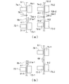
第2搬送装置D2において、第2光学フィルムロール体5-2から別の第2ダミーフィルム32-2を繰り出し、第2ダミーフィルム32-2の回収用芯部材79-2に巻き取っていく。その過程でセンサー(図示せず)が別の第2ダミーフィルム32-2と第2光学フィルム6-2の連結部分d-2(別の第2ダミーフィルム32-2の後端部32b-2と第2光学フィルム6-2の先端部6a-2が連結された部分)を検知する。すると、図15(a)に示すように、第2吸着手段72-2及び第2固定部材73-2が、第2光学フィルム6-2を挟み込んで固定し、第2搬送側吸着手段74-2及び第2搬送側固定部材75-2が、別の第2ダミーフィルム32-2を挟み込んで固定する。次に、第2切断手段76-2が、前記連結部分d-2の上流側において、第2光学フィルム6-2を幅方向に切断し、別の第2ダミーフィルム32-2を第2光学フィルム6-2から分離する。この際、切断後の第2光学フィルム6-2に連結部分d-2が含まれないように、第2切断手段76-2にて切断することが好ましい。例えば、図15(a)に示すように、連結部分d-2の端から所定長さW-2離れた箇所で切断する。前記所定長さW-2としては、10cm以内などが挙げられる。なお、切断後の別の第2ダミーフィルム32-2は、回収用芯部材79-2に巻き取られる。
第2搬送装置D2においては、前記のように第2光学フィルム6-2を分離した後、この第2光学フィルム6-2の端部が第2吸着手段72-2及び第2固定部材73-2によって固定された状態で、後述する接合処理まで待機しておく。
第2搬送装置D2においては、前記のように第2光学フィルム6-2を分離した後、この第2光学フィルム6-2の端部が第2吸着手段72-2及び第2固定部材73-2によって固定された状態で、後述する接合処理まで待機しておく。
・接合処理
一方、第1搬送装置D1においては、第1光学フィルム6-1が加工機Eへと搬送されている。第1光学フィルムロール体5-1から全ての第1光学フィルム6-1を繰り出されると、仮止め手段が解除され(図10での説明参照)、第1ダミーフィルム31-1が繰り出される。第1光学フィルム6-1に続いて第1ダミーフィルム31-1が繰り出されると、センサー(図示せず)が第1光学フィルム6-1と第1ダミーフィルム31-1の連結部分d-1(第1光学フィルム6-1の後端部6b-1と第1ダミーフィルム31-1の先端部31a-1が連結された部分)を検知する。すると、図15(a)に示すように、第1吸着手段72-1及び第1固定部材73-1が、第1ダミーフィルム31-1を挟み込んで固定し、第1搬送側吸着手段74-1及び第1搬送側固定部材75-1が、第1光学フィルム6-1を挟み込んで固定する。次に、第1切断手段76-1が、前記連結部分d-1の下流側において、第1光学フィルム6-1を幅方向に切断し、第1光学フィルム6-1を第1ダミーフィルム31-1から分離する。この際、切断後の第1光学フィルム6-1に連結部分d-1が含まれないように、第1切断手段76-1にて切断することが好ましい。例えば、図15(a)に示すように、連結部分d-1の端から所定長さW-1離れた箇所で切断する。前記所定長さW-1としては、10cm以内などが挙げられる。
一方、第1搬送装置D1においては、第1光学フィルム6-1が加工機Eへと搬送されている。第1光学フィルムロール体5-1から全ての第1光学フィルム6-1を繰り出されると、仮止め手段が解除され(図10での説明参照)、第1ダミーフィルム31-1が繰り出される。第1光学フィルム6-1に続いて第1ダミーフィルム31-1が繰り出されると、センサー(図示せず)が第1光学フィルム6-1と第1ダミーフィルム31-1の連結部分d-1(第1光学フィルム6-1の後端部6b-1と第1ダミーフィルム31-1の先端部31a-1が連結された部分)を検知する。すると、図15(a)に示すように、第1吸着手段72-1及び第1固定部材73-1が、第1ダミーフィルム31-1を挟み込んで固定し、第1搬送側吸着手段74-1及び第1搬送側固定部材75-1が、第1光学フィルム6-1を挟み込んで固定する。次に、第1切断手段76-1が、前記連結部分d-1の下流側において、第1光学フィルム6-1を幅方向に切断し、第1光学フィルム6-1を第1ダミーフィルム31-1から分離する。この際、切断後の第1光学フィルム6-1に連結部分d-1が含まれないように、第1切断手段76-1にて切断することが好ましい。例えば、図15(a)に示すように、連結部分d-1の端から所定長さW-1離れた箇所で切断する。前記所定長さW-1としては、10cm以内などが挙げられる。
同図(b)及び図16に示すように、分離した第1光学フィルム6-1の端部を固定した第1搬送側吸着手段74-1及び第1搬送側固定部材75-1を、前記待機状態の第2光学フィルム6-2の端部へ移動させる。なお、第2光学フィルム6-2の端部を固定した第2吸着手段72-2及び第2固定部材73-2を、第1光学フィルム6-1の端部へ移動させてもよく、或いは、双方を相対移動させてもよい。
次に、第1光学フィルム6-1の端部と第2光学フィルム6-2の端部を、粘着テープ69などを用いて連結する。その後、図16に示すように、第1搬送側吸着手段74-1及び第1搬送側固定部材75-1による第1光学フィルム6-1の固定及び第2吸着手段72-2及び第2固定部材73-2による第2光学フィルム6-2の固定をそれぞれ解除する。事後、第1光学フィルム6-1に続いて第2光学フィルム6-2が加工機Eへと送られていく。
このようにして、先行する第1光学フィルム6-1に後続の第2光学フィルム6-2を接合して、光学フィルムを加工機Eに連続的に供給できる。
このようにして、先行する第1光学フィルム6-1に後続の第2光学フィルム6-2を接合して、光学フィルムを加工機Eに連続的に供給できる。
本発明の光学フィルムロール体51は、芯部材2と光学フィルム6の間にダミーフィルム31が介在されている。このため、芯部材2から2つの光学フィルム(先行する第1光学フィルムと後続の第2光学フィルム)を接合する箇所までを、ダミーフィルム31で構成できる。つまり、図16に示すように、第1ダミーフィルム31-1によって、先行する第1光学フィルム6-1を、2つのフィルムを接合する箇所Yまで搬送できる。このため、光学フィルムを無駄にすることなく、2つの光学フィルムを接合できる。
第1ダミーフィルム31-1は、廃棄してもよいが、好ましくは、再び芯部材2に巻き取り且つ先端部を仮止め手段によって仮止めすることにより、再利用できる。つまり、1度使用したダミーフィルム31を巻き戻すことにより、光学フィルム用巻き芯1を再生できる。
ダミーフィルムは、ポリエチレンテレフタレートフィルムなどの汎用的な合成樹脂フィルムなどを用いればよいので、光学フィルムに比して安価である。このため、本発明の光学フィルムロール体を用いれば、従来のように光学フィルムの端材を廃棄する場合に比して、製造コストを削減できる。
第1ダミーフィルム31-1は、廃棄してもよいが、好ましくは、再び芯部材2に巻き取り且つ先端部を仮止め手段によって仮止めすることにより、再利用できる。つまり、1度使用したダミーフィルム31を巻き戻すことにより、光学フィルム用巻き芯1を再生できる。
ダミーフィルムは、ポリエチレンテレフタレートフィルムなどの汎用的な合成樹脂フィルムなどを用いればよいので、光学フィルムに比して安価である。このため、本発明の光学フィルムロール体を用いれば、従来のように光学フィルムの端材を廃棄する場合に比して、製造コストを削減できる。
また、別のダミーフィルム32が連結されている光学フィルムロール体52にあっては、芯部材2に取り付けられたダミーフィルム31だけでなく、この別のダミーフィルム32も光学フィルム6の廃棄ロスの発生防止に貢献する。
例えば、上記のように第1光学フィルム6-1に第2光学フィルム6-2を接合する場合、第2光学フィルム6-2を2つのフィルムを接合する箇所Yまで搬送する必要がある。この場合、第2光学フィルム6-2の先端部を回収用芯部材79-2に直接取り付けると、前記箇所Yから回収用芯部材79-2までの第2光学フィルム6-2は、第1光学フィルム6-1に接合されなくなる。つまり、箇所Yから回収用芯部材79-2までの第2光学フィルム6-2は、端材として回収用芯部材79-2に巻き取られて廃棄される。
この点、別のダミーフィルム32が連結されている光学フィルムロール体52を用いることにより、図14及び図16に示すように、2つのフィルムを接合する箇所Yから回収用芯部材79-2までを、別の第2ダミーフィルム32-2で構成できる。つまり、第2ダミーフィルム32-2によって、第2光学フィルム6-2を、2つのフィルムを接合する箇所Yまで搬送できる。このため、光学フィルムを無駄にすることなく、2つの光学フィルムを接合できる。
例えば、上記のように第1光学フィルム6-1に第2光学フィルム6-2を接合する場合、第2光学フィルム6-2を2つのフィルムを接合する箇所Yまで搬送する必要がある。この場合、第2光学フィルム6-2の先端部を回収用芯部材79-2に直接取り付けると、前記箇所Yから回収用芯部材79-2までの第2光学フィルム6-2は、第1光学フィルム6-1に接合されなくなる。つまり、箇所Yから回収用芯部材79-2までの第2光学フィルム6-2は、端材として回収用芯部材79-2に巻き取られて廃棄される。
この点、別のダミーフィルム32が連結されている光学フィルムロール体52を用いることにより、図14及び図16に示すように、2つのフィルムを接合する箇所Yから回収用芯部材79-2までを、別の第2ダミーフィルム32-2で構成できる。つまり、第2ダミーフィルム32-2によって、第2光学フィルム6-2を、2つのフィルムを接合する箇所Yまで搬送できる。このため、光学フィルムを無駄にすることなく、2つの光学フィルムを接合できる。
1 光学フィルム用巻き芯
2 芯部材
31 ダミーフィルム
31a ダミーフィルムの先端部
32 別のダミーフィルム
4 仮止めテープ
43 切断補助線
51,52 光学フィルムロール体
6 光学フィルム
6a 光学フィルムの先端部
6b 光学フィルムの後端部
2 芯部材
31 ダミーフィルム
31a ダミーフィルムの先端部
32 別のダミーフィルム
4 仮止めテープ
43 切断補助線
51,52 光学フィルムロール体
6 光学フィルム
6a 光学フィルムの先端部
6b 光学フィルムの後端部
Claims (6)
- 芯部材と、
前記芯部材に巻き付けられたダミーフィルムであって、光学フィルムが連結され得る先端部を有するダミーフィルムと、
を有する光学フィルム用巻き芯。 - 前記ダミーフィルムの先端部が、展開防止のために仮止めされている、請求項1に記載の光学フィルム用巻き芯。
- 前記ダミーフィルムが前記芯部材に1周以上巻き付けられることによって、前記芯部材の周囲にダミーフィルム層が形成されており、
前記ダミーフィルムの先端部と前記ダミーフィルム層の表面に跨がって、仮止めテープが貼り付けられており、
前記仮止めテープには、前記ダミーフィルムの先端部の縁又はその近傍に沿って、切断補助線が形成されている、請求項1または2に記載の光学フィルム用巻き芯。 - 請求項1乃至3のいずれか一項に記載の光学フィルム用巻き芯と、前記巻き芯に巻き付けられた光学フィルムと、を有し、
前記光学フィルムの後端部と前記ダミーフィルムの先端部が連結された状態で、前記光学フィルムが前記巻き芯に巻き付けられている、光学フィルムロール体。 - 前記光学フィルムの先端部に、別のダミーフィルムが連結されている、請求項4に記載の光学フィルムロール体。
- 請求項4または5のいずれかに記載の光学フィルムロール体から光学フィルムを引き出した後、前記ダミーフィルムから前記光学フィルムを分離し、この光学フィルムと別の光学フィルムを接合して搬送する、光学フィルムの連続供給方法。
Priority Applications (2)
| Application Number | Priority Date | Filing Date | Title |
|---|---|---|---|
| KR1020217007248A KR102716333B1 (ko) | 2018-12-04 | 2019-08-07 | 광학 필름용 권심, 광학 필름 롤체, 및 광학 필름의 연속 공급 방법 |
| CN201980068677.XA CN112912326A (zh) | 2018-12-04 | 2019-08-07 | 光学膜用卷芯、光学膜卷筒体及光学膜的连续供给方法 |
Applications Claiming Priority (2)
| Application Number | Priority Date | Filing Date | Title |
|---|---|---|---|
| JP2018227086A JP7194571B2 (ja) | 2018-12-04 | 2018-12-04 | 光学フィルム用巻き芯、光学フィルムロール体、及び光学フィルムの連続供給方法 |
| JP2018-227086 | 2018-12-04 |
Publications (1)
| Publication Number | Publication Date |
|---|---|
| WO2020115947A1 true WO2020115947A1 (ja) | 2020-06-11 |
Family
ID=70974220
Family Applications (1)
| Application Number | Title | Priority Date | Filing Date |
|---|---|---|---|
| PCT/JP2019/031130 Ceased WO2020115947A1 (ja) | 2018-12-04 | 2019-08-07 | 光学フィルム用巻き芯、光学フィルムロール体、及び光学フィルムの連続供給方法 |
Country Status (4)
| Country | Link |
|---|---|
| JP (1) | JP7194571B2 (ja) |
| KR (1) | KR102716333B1 (ja) |
| CN (1) | CN112912326A (ja) |
| WO (1) | WO2020115947A1 (ja) |
Cited By (2)
| Publication number | Priority date | Publication date | Assignee | Title |
|---|---|---|---|---|
| CN111776832A (zh) * | 2020-07-16 | 2020-10-16 | 湖北亿纬动力有限公司 | 一种极片收卷方式及薄膜分切收卷装置 |
| CN117142203A (zh) * | 2023-09-12 | 2023-12-01 | 广东包庄科技有限公司 | 一种自动收卷系统以及自动收卷方法 |
Families Citing this family (2)
| Publication number | Priority date | Publication date | Assignee | Title |
|---|---|---|---|---|
| JP7460567B2 (ja) * | 2021-03-05 | 2024-04-02 | 日東電工株式会社 | 巻き取りロールおよび該巻き取りロールに巻き取られた光学フィルムロール |
| KR102381970B1 (ko) * | 2021-07-26 | 2022-04-01 | 김규철 | 코어용 연결필름 부착장치 |
Citations (5)
| Publication number | Priority date | Publication date | Assignee | Title |
|---|---|---|---|---|
| JPH0958906A (ja) * | 1995-08-28 | 1997-03-04 | Toyo Alum Kk | コイル状物の端末構造 |
| JP2004026468A (ja) * | 2002-06-28 | 2004-01-29 | Kanebo Ltd | 筒状支持体及び、当該支持体を用いたフィルム又はシートの巻取方法 |
| JP2006096485A (ja) * | 2004-09-28 | 2006-04-13 | Sato Corp | 接合シールおよびシートロール |
| WO2018074383A1 (ja) * | 2016-10-17 | 2018-04-26 | 日本電気硝子株式会社 | ガラスロール |
| JP6390848B2 (ja) * | 2014-06-26 | 2018-09-19 | 日東電工株式会社 | 光学フィルム連続供給装置及び光学フィルム連続供給方法 |
Family Cites Families (4)
| Publication number | Priority date | Publication date | Assignee | Title |
|---|---|---|---|---|
| JPS6390848U (ja) | 1986-12-04 | 1988-06-13 | ||
| JP5548593B2 (ja) | 2010-01-13 | 2014-07-16 | 日東電工株式会社 | シート接合体の製造方法、シート接合体、ロール体、光学用フィルム、及び偏光フィルム |
| CN204750705U (zh) * | 2015-06-23 | 2015-11-11 | 山东天振药业有限公司 | 一种自动充填包装机的薄膜放卷机构 |
| JP6699159B2 (ja) * | 2015-12-17 | 2020-05-27 | 日本電気硝子株式会社 | ガラスロール及びその製造方法 |
-
2018
- 2018-12-04 JP JP2018227086A patent/JP7194571B2/ja active Active
-
2019
- 2019-08-07 WO PCT/JP2019/031130 patent/WO2020115947A1/ja not_active Ceased
- 2019-08-07 CN CN201980068677.XA patent/CN112912326A/zh active Pending
- 2019-08-07 KR KR1020217007248A patent/KR102716333B1/ko active Active
Patent Citations (5)
| Publication number | Priority date | Publication date | Assignee | Title |
|---|---|---|---|---|
| JPH0958906A (ja) * | 1995-08-28 | 1997-03-04 | Toyo Alum Kk | コイル状物の端末構造 |
| JP2004026468A (ja) * | 2002-06-28 | 2004-01-29 | Kanebo Ltd | 筒状支持体及び、当該支持体を用いたフィルム又はシートの巻取方法 |
| JP2006096485A (ja) * | 2004-09-28 | 2006-04-13 | Sato Corp | 接合シールおよびシートロール |
| JP6390848B2 (ja) * | 2014-06-26 | 2018-09-19 | 日東電工株式会社 | 光学フィルム連続供給装置及び光学フィルム連続供給方法 |
| WO2018074383A1 (ja) * | 2016-10-17 | 2018-04-26 | 日本電気硝子株式会社 | ガラスロール |
Cited By (3)
| Publication number | Priority date | Publication date | Assignee | Title |
|---|---|---|---|---|
| CN111776832A (zh) * | 2020-07-16 | 2020-10-16 | 湖北亿纬动力有限公司 | 一种极片收卷方式及薄膜分切收卷装置 |
| CN117142203A (zh) * | 2023-09-12 | 2023-12-01 | 广东包庄科技有限公司 | 一种自动收卷系统以及自动收卷方法 |
| CN117142203B (zh) * | 2023-09-12 | 2026-03-06 | 广东包庄科技有限公司 | 一种自动收卷系统以及自动收卷方法 |
Also Published As
| Publication number | Publication date |
|---|---|
| JP7194571B2 (ja) | 2022-12-22 |
| JP2020090341A (ja) | 2020-06-11 |
| CN112912326A (zh) | 2021-06-04 |
| KR20210097689A (ko) | 2021-08-09 |
| KR102716333B1 (ko) | 2024-10-15 |
Similar Documents
| Publication | Publication Date | Title |
|---|---|---|
| WO2020115947A1 (ja) | 光学フィルム用巻き芯、光学フィルムロール体、及び光学フィルムの連続供給方法 | |
| JP4326635B2 (ja) | ガラスフィルムの取扱い方法及びガラス積層体 | |
| CN102834339A (zh) | 剥离方法以及剥离装置 | |
| TWI753691B (zh) | 光學膜之沖壓裝置、及薄膜製品之製造方法 | |
| JP2023177237A (ja) | 巻取りロール | |
| JP2023177088A (ja) | 巻取りロール | |
| KR20180085444A (ko) | 이형지 분리가 용이한 양면접착테이프 및 그 제조방법 | |
| JP5889729B2 (ja) | ゴム帯状部材の巻取りライナー | |
| WO2022162983A1 (ja) | フィルム製品の製造方法及びその製造装置 | |
| JP3964892B2 (ja) | 巻芯 | |
| JP6550311B2 (ja) | 剥離方法 | |
| TWI756972B (zh) | 薄膜製品之製造方法、及其製造裝置 | |
| KR102454591B1 (ko) | 단층체 또는 적층체의 제조 방법 | |
| TW201540515A (zh) | 薄膜貼合裝置、薄膜貼合方法及層積薄膜 | |
| TW201132501A (en) | Optical film bonding apparatus and optical film bonding method | |
| CN101750789A (zh) | 光学显示装置制造方法以及光学显示装置制造用辊卷 | |
| JP2000007228A (ja) | 材料ラップロ―ル、該材料ラップロ―ルを製造する方法および該方法を実施するための装置 | |
| KR101685328B1 (ko) | 광학필름 제조방법 및 광학필름 | |
| ES2315506T3 (es) | Metodo y aparato para conectar peliculas de resina. | |
| JP6454545B2 (ja) | 偏光板の製造方法 | |
| JP2004085729A (ja) | 多層ラベル及び多層ラベルの製造方法 | |
| JP2010217878A (ja) | 光学表示ユニットの製造システム及び製造方法、並びに、ロール原反 | |
| JP6732580B2 (ja) | 光学表示パネルの製造方法と光学表示パネルの製造システム | |
| JP3647820B2 (ja) | 結束テープの製造方法 | |
| JPH04303354A (ja) | 積層シートの連結方法 |
Legal Events
| Date | Code | Title | Description |
|---|---|---|---|
| 121 | Ep: the epo has been informed by wipo that ep was designated in this application |
Ref document number: 19892050 Country of ref document: EP Kind code of ref document: A1 |
|
| ENP | Entry into the national phase |
Ref document number: 20217007248 Country of ref document: KR Kind code of ref document: A |
|
| NENP | Non-entry into the national phase |
Ref country code: DE |
|
| 122 | Ep: pct application non-entry in european phase |
Ref document number: 19892050 Country of ref document: EP Kind code of ref document: A1 |