WO2020111066A1 - フッ素樹脂成形品の製造方法および製造システム - Google Patents
フッ素樹脂成形品の製造方法および製造システム Download PDFInfo
- Publication number
- WO2020111066A1 WO2020111066A1 PCT/JP2019/046187 JP2019046187W WO2020111066A1 WO 2020111066 A1 WO2020111066 A1 WO 2020111066A1 JP 2019046187 W JP2019046187 W JP 2019046187W WO 2020111066 A1 WO2020111066 A1 WO 2020111066A1
- Authority
- WO
- WIPO (PCT)
- Prior art keywords
- particles
- water
- cleaning
- molded article
- fluororesin molded
- Prior art date
- Legal status (The legal status is an assumption and is not a legal conclusion. Google has not performed a legal analysis and makes no representation as to the accuracy of the status listed.)
- Ceased
Links
Images

Classifications
-
- C—CHEMISTRY; METALLURGY
- C11—ANIMAL OR VEGETABLE OILS, FATS, FATTY SUBSTANCES OR WAXES; FATTY ACIDS THEREFROM; DETERGENTS; CANDLES
- C11D—DETERGENT COMPOSITIONS; USE OF SINGLE SUBSTANCES AS DETERGENTS; SOAP OR SOAP-MAKING; RESIN SOAPS; RECOVERY OF GLYCEROL
- C11D7/00—Compositions of detergents based essentially on non-surface-active compounds
- C11D7/22—Organic compounds
- C11D7/26—Organic compounds containing oxygen
- C11D7/261—Alcohols; Phenols
-
- B—PERFORMING OPERATIONS; TRANSPORTING
- B08—CLEANING
- B08B—CLEANING IN GENERAL; PREVENTION OF FOULING IN GENERAL
- B08B9/00—Cleaning hollow articles by methods or apparatus specially adapted thereto
- B08B9/02—Cleaning pipes or tubes or systems of pipes or tubes
- B08B9/027—Cleaning the internal surfaces; Removal of blockages
-
- B—PERFORMING OPERATIONS; TRANSPORTING
- B08—CLEANING
- B08B—CLEANING IN GENERAL; PREVENTION OF FOULING IN GENERAL
- B08B9/00—Cleaning hollow articles by methods or apparatus specially adapted thereto
- B08B9/02—Cleaning pipes or tubes or systems of pipes or tubes
- B08B9/027—Cleaning the internal surfaces; Removal of blockages
- B08B9/032—Cleaning the internal surfaces; Removal of blockages by the mechanical action of a moving fluid, e.g. by flushing
-
- B—PERFORMING OPERATIONS; TRANSPORTING
- B08—CLEANING
- B08B—CLEANING IN GENERAL; PREVENTION OF FOULING IN GENERAL
- B08B3/00—Cleaning by methods involving the use or presence of liquid or steam
- B08B3/04—Cleaning involving contact with liquid
-
- B—PERFORMING OPERATIONS; TRANSPORTING
- B29—WORKING OF PLASTICS; WORKING OF SUBSTANCES IN A PLASTIC STATE IN GENERAL
- B29C—SHAPING OR JOINING OF PLASTICS; SHAPING OF MATERIAL IN A PLASTIC STATE, NOT OTHERWISE PROVIDED FOR; AFTER-TREATMENT OF THE SHAPED PRODUCTS, e.g. REPAIRING
- B29C71/00—After-treatment of articles without altering their shape; Apparatus therefor
- B29C71/0009—After-treatment of articles without altering their shape; Apparatus therefor using liquids, e.g. solvents, swelling agents
-
- C—CHEMISTRY; METALLURGY
- C08—ORGANIC MACROMOLECULAR COMPOUNDS; THEIR PREPARATION OR CHEMICAL WORKING-UP; COMPOSITIONS BASED THEREON
- C08J—WORKING-UP; GENERAL PROCESSES OF COMPOUNDING; AFTER-TREATMENT NOT COVERED BY SUBCLASSES C08B, C08C, C08F, C08G or C08H
- C08J7/00—Chemical treatment or coating of shaped articles made of macromolecular substances
-
- C—CHEMISTRY; METALLURGY
- C08—ORGANIC MACROMOLECULAR COMPOUNDS; THEIR PREPARATION OR CHEMICAL WORKING-UP; COMPOSITIONS BASED THEREON
- C08J—WORKING-UP; GENERAL PROCESSES OF COMPOUNDING; AFTER-TREATMENT NOT COVERED BY SUBCLASSES C08B, C08C, C08F, C08G or C08H
- C08J7/00—Chemical treatment or coating of shaped articles made of macromolecular substances
- C08J7/02—Chemical treatment or coating of shaped articles made of macromolecular substances with solvents, e.g. swelling agents
-
- C—CHEMISTRY; METALLURGY
- C08—ORGANIC MACROMOLECULAR COMPOUNDS; THEIR PREPARATION OR CHEMICAL WORKING-UP; COMPOSITIONS BASED THEREON
- C08K—Use of inorganic or non-macromolecular organic substances as compounding ingredients
- C08K5/00—Use of organic ingredients
- C08K5/04—Oxygen-containing compounds
- C08K5/05—Alcohols; Metal alcoholates
-
- C—CHEMISTRY; METALLURGY
- C08—ORGANIC MACROMOLECULAR COMPOUNDS; THEIR PREPARATION OR CHEMICAL WORKING-UP; COMPOSITIONS BASED THEREON
- C08L—COMPOSITIONS OF MACROMOLECULAR COMPOUNDS
- C08L27/00—Compositions of homopolymers or copolymers of compounds having one or more unsaturated aliphatic radicals, each having only one carbon-to-carbon double bond, and at least one being terminated by a halogen; Compositions of derivatives of such polymers
- C08L27/02—Compositions of homopolymers or copolymers of compounds having one or more unsaturated aliphatic radicals, each having only one carbon-to-carbon double bond, and at least one being terminated by a halogen; Compositions of derivatives of such polymers not modified by chemical after-treatment
- C08L27/12—Compositions of homopolymers or copolymers of compounds having one or more unsaturated aliphatic radicals, each having only one carbon-to-carbon double bond, and at least one being terminated by a halogen; Compositions of derivatives of such polymers not modified by chemical after-treatment containing fluorine atoms
- C08L27/18—Homopolymers or copolymers or tetrafluoroethene
-
- C—CHEMISTRY; METALLURGY
- C11—ANIMAL OR VEGETABLE OILS, FATS, FATTY SUBSTANCES OR WAXES; FATTY ACIDS THEREFROM; DETERGENTS; CANDLES
- C11D—DETERGENT COMPOSITIONS; USE OF SINGLE SUBSTANCES AS DETERGENTS; SOAP OR SOAP-MAKING; RESIN SOAPS; RECOVERY OF GLYCEROL
- C11D7/00—Compositions of detergents based essentially on non-surface-active compounds
- C11D7/02—Inorganic compounds
-
- C—CHEMISTRY; METALLURGY
- C11—ANIMAL OR VEGETABLE OILS, FATS, FATTY SUBSTANCES OR WAXES; FATTY ACIDS THEREFROM; DETERGENTS; CANDLES
- C11D—DETERGENT COMPOSITIONS; USE OF SINGLE SUBSTANCES AS DETERGENTS; SOAP OR SOAP-MAKING; RESIN SOAPS; RECOVERY OF GLYCEROL
- C11D7/00—Compositions of detergents based essentially on non-surface-active compounds
- C11D7/22—Organic compounds
- C11D7/26—Organic compounds containing oxygen
-
- C—CHEMISTRY; METALLURGY
- C11—ANIMAL OR VEGETABLE OILS, FATS, FATTY SUBSTANCES OR WAXES; FATTY ACIDS THEREFROM; DETERGENTS; CANDLES
- C11D—DETERGENT COMPOSITIONS; USE OF SINGLE SUBSTANCES AS DETERGENTS; SOAP OR SOAP-MAKING; RESIN SOAPS; RECOVERY OF GLYCEROL
- C11D7/00—Compositions of detergents based essentially on non-surface-active compounds
- C11D7/50—Solvents
-
- H—ELECTRICITY
- H10—SEMICONDUCTOR DEVICES; ELECTRIC SOLID-STATE DEVICES NOT OTHERWISE PROVIDED FOR
- H10P—GENERIC PROCESSES OR APPARATUS FOR THE MANUFACTURE OR TREATMENT OF DEVICES COVERED BY CLASS H10
- H10P52/00—Grinding, lapping or polishing of wafers, substrates or parts of devices
-
- B—PERFORMING OPERATIONS; TRANSPORTING
- B08—CLEANING
- B08B—CLEANING IN GENERAL; PREVENTION OF FOULING IN GENERAL
- B08B2209/00—Details of machines or methods for cleaning hollow articles
- B08B2209/02—Details of apparatuses or methods for cleaning pipes or tubes
- B08B2209/027—Details of apparatuses or methods for cleaning pipes or tubes for cleaning the internal surfaces
- B08B2209/032—Details of apparatuses or methods for cleaning pipes or tubes for cleaning the internal surfaces by the mechanical action of a moving fluid
-
- B—PERFORMING OPERATIONS; TRANSPORTING
- B08—CLEANING
- B08B—CLEANING IN GENERAL; PREVENTION OF FOULING IN GENERAL
- B08B2240/00—Type of materials or objects being cleaned
-
- B—PERFORMING OPERATIONS; TRANSPORTING
- B29—WORKING OF PLASTICS; WORKING OF SUBSTANCES IN A PLASTIC STATE IN GENERAL
- B29C—SHAPING OR JOINING OF PLASTICS; SHAPING OF MATERIAL IN A PLASTIC STATE, NOT OTHERWISE PROVIDED FOR; AFTER-TREATMENT OF THE SHAPED PRODUCTS, e.g. REPAIRING
- B29C71/00—After-treatment of articles without altering their shape; Apparatus therefor
- B29C71/0009—After-treatment of articles without altering their shape; Apparatus therefor using liquids, e.g. solvents, swelling agents
- B29C2071/0018—Absorbing ingredients, e.g. drugs, flavourings, UV screeners, embedded in the articles
-
- C—CHEMISTRY; METALLURGY
- C08—ORGANIC MACROMOLECULAR COMPOUNDS; THEIR PREPARATION OR CHEMICAL WORKING-UP; COMPOSITIONS BASED THEREON
- C08F—MACROMOLECULAR COMPOUNDS OBTAINED BY REACTIONS ONLY INVOLVING CARBON-TO-CARBON UNSATURATED BONDS
- C08F214/00—Copolymers of compounds having one or more unsaturated aliphatic radicals, each having only one carbon-to-carbon double bond, and at least one being terminated by a halogen
- C08F214/18—Monomers containing fluorine
- C08F214/26—Tetrafluoroethene
- C08F214/262—Tetrafluoroethene with fluorinated vinyl ethers
-
- C—CHEMISTRY; METALLURGY
- C08—ORGANIC MACROMOLECULAR COMPOUNDS; THEIR PREPARATION OR CHEMICAL WORKING-UP; COMPOSITIONS BASED THEREON
- C08J—WORKING-UP; GENERAL PROCESSES OF COMPOUNDING; AFTER-TREATMENT NOT COVERED BY SUBCLASSES C08B, C08C, C08F, C08G or C08H
- C08J2327/00—Characterised by the use of homopolymers or copolymers of compounds having one or more unsaturated aliphatic radicals, each having only one carbon-to-carbon double bond, and at least one being terminated by a halogen; Derivatives of such polymers
- C08J2327/02—Characterised by the use of homopolymers or copolymers of compounds having one or more unsaturated aliphatic radicals, each having only one carbon-to-carbon double bond, and at least one being terminated by a halogen; Derivatives of such polymers not modified by chemical after-treatment
- C08J2327/12—Characterised by the use of homopolymers or copolymers of compounds having one or more unsaturated aliphatic radicals, each having only one carbon-to-carbon double bond, and at least one being terminated by a halogen; Derivatives of such polymers not modified by chemical after-treatment containing fluorine atoms
- C08J2327/18—Homopolymers or copolymers of tetrafluoroethylene
Definitions
- the present disclosure relates to a method and a system for manufacturing a fluororesin molded article.
- Patent Document 1 discloses a cleaning method for removing particles adhering to the surface of a fluororesin molded article used in a semiconductor manufacturing apparatus, which is used in a semiconductor manufacturing apparatus for cleaning using a cleaning agent containing a fluorine-substituted solvent. Cleaning methods for resin molded products have been proposed.
- Fluororesin molded products are used as tubes for transferring chemicals used to manufacture semiconductor devices.
- semiconductor devices With the recent miniaturization of semiconductor devices, there is a demand for a technique for reducing the number of particles generated from a fluororesin molded article to a level that has never been achieved.
- the present disclosure aims to provide a manufacturing method and a manufacturing system for manufacturing a fluororesin molded article in which particles are less likely to occur.
- a method for producing a washed fluororesin molded article which includes a step of washing the fluororesin molded article with a chemical solution, and a step of washing the fluororesin molded article with water.
- the chemical solution is preferably alcohol or an alcohol aqueous solution.
- the chemical liquid is alcohol or an aqueous alcohol solution having an alcohol concentration of 20 to 100% by mass.
- the chemical solution is preferably an alkaline aqueous solution having a pH of 8 or more.
- the chemical solution is preferably an aqueous ammonia solution.
- the cleaning with the chemical liquid is a flow cleaning.
- the washing with water is preferably washing with running water.
- the fluororesin molded article contains a tetrafluoroethylene/perfluoro(alkyl vinyl ether) copolymer as the fluororesin.
- the fluororesin molded article is preferably a tube.
- the manufacturing method of the present disclosure further includes a step of removing particles from the chemical solution used for cleaning, and a step of reusing the chemical solution from which particles have been removed as at least a part of the chemical solution used in the step of cleaning with the chemical solution.
- the production method of the present disclosure further includes a step of removing particles from the water used for cleaning, and a step of reusing the water from which particles have been removed as at least a part of water used in the step of cleaning with water.
- a step of removing particles from the water used for cleaning and a step of reusing the water from which particles have been removed as at least a part of water used in the step of cleaning with water.
- a manufacturing system for manufacturing a washed fluororesin molded article, the first filtering means for removing particles from a chemical liquid, and the second filtering means for removing particles from water.
- a filtering means for switching the supply of water from the second filtering means to the cleaning means, first returning means for returning the chemical liquid used for cleaning from the cleaning means to the first filtering means, and for cleaning And a second return means for returning the stored water from the cleaning means to the second filtration means.
- FIG. 2 is a diagram for explaining a method for measuring the number of particles.
- a fluororesin material with a reduced content of particle-causing substances As a method of reducing the generation of particles from a fluororesin molded product, it is possible to use a fluororesin material with a reduced content of particle-causing substances as a raw material for the molded product.
- a fluororesin material for example, a fluororesin material in which volatile low molecular weight substances are reduced has been proposed.
- the raw materials are appropriately selected, it may not be possible to sufficiently suppress the generation of particles.
- the fluororesin material when the fluororesin material is subjected to primary processing and then subjected to secondary processing such as bending or butt welding, the fluororesin material may be heated to a temperature equal to or higher than the melting point to be melted plural times until the molding is completed. ..
- the manufacturing method of the present disclosure is a manufacturing method for manufacturing a washed fluororesin molded article, and includes a step of washing the fluororesin molded article with a chemical solution, and a step of washing the fluororesin molded article with water. .
- the manufacturing method of the present disclosure can be used for a fluororesin molded product obtained by secondary processing, it is possible to manufacture a fluororesin molded product in which particles attached during secondary processing are also removed. .
- the order of performing the cleaning step with the chemical solution and the cleaning step with water is not limited, and the number of times each step is performed is also not limited.
- the cleaning step with water may be performed after the cleaning step with the chemical solution, or the cleaning step with the chemical solution may be performed after the cleaning step with water.
- the chemical liquid used in the cleaning step with the chemical liquid is not particularly limited as long as it is a liquid other than water, and may be a liquid chemical or a solution containing the chemical. However, it is preferable to use a specific chemical liquid for the following reasons, because a fluororesin molded article in which the generation of particles is further suppressed can be produced.
- the particles from the fluororesin molded product include particles of an inorganic substance and particles of an organic substance. Therefore, in order to suppress the generation of particles from the fluororesin molded product, it is required to remove both the inorganic substance and the organic substance adhering to the surface of the fluororesin molded product.
- Inorganic substances include metal oxides, non-metal oxides, or salts, which are removed from the surface of the fluororesin molded article mainly by performing a washing step with water.
- the organic substance includes components derived from a plasticizer existing in the molding atmosphere of the fluororesin, carbons floating in the air, particles derived from the fluororesin material, and the like.
- fluorine-based particles are particularly difficult to remove in the washing step with water, and are preferably removed in the washing step with a chemical solution.
- the fluorine-based particles are particles containing carbon atoms and fluorine atoms. Therefore, in the cleaning step with the chemical solution in the manufacturing method of the present disclosure, it is preferable to use a chemical solution that can easily remove the fluorine-based particles that are particles unique to the fluororesin molded article and that are difficult to clean with water.
- a chemical solution that easily wets the fluorine-based particles is preferable, and examples thereof include a non-fluorine-based solvent or a fluorine-based solvent.
- a fluorine-based solvent is used, the fluorine-based particles can be dissolved and removed from the surface of the fluororesin molded article.
- a non-fluorine-based solvent that has a small economical burden and is easy to handle can be preferably used. ..
- a liquid chemical having a relatively low surface tension, or a comparison Aqueous solutions containing chemicals with relatively low surface tension are preferred.
- the surface tension of the liquid chemical or the chemical contained in the aqueous solution is preferably 28 mN/m or less, more preferably 24 mN/m or less, since it is possible to produce a fluororesin molded article in which generation of particles is further suppressed.
- the lower limit is not particularly limited, but may be 20 mN/m or more.
- an alcohol or an alcohol aqueous solution is preferable, an alcohol having 1 to 10 carbon atoms or an aqueous solution thereof is more preferable, and a carbon number of 1 to 1 is preferable because a fluororesin molded article in which generation of particles is further suppressed can be produced.
- the alcohol of 4 or an aqueous solution thereof is more preferable, methanol, ethanol, isopropyl alcohol or an aqueous solution thereof is particularly preferable, and isopropyl alcohol or an aqueous solution thereof is most preferable because of its high detergency and volatility.
- the alcohol concentration of the alcohol and the alcohol aqueous solution is preferably 20% by mass or more, more preferably 25% by mass or more, and further preferably 30 because the fluororesin molded article in which the generation of particles is further suppressed can be produced. It is at least mass%, particularly preferably at least 40 mass%, preferably at most 100 mass%. From the viewpoint of safety and economy, the alcohol concentration may be 80% by mass or less, and may be 60% by mass or less. Safety during cleaning by using an aqueous alcohol solution having an alcohol concentration of preferably 20 to 80% by mass, more preferably 25 to 60% by mass, further preferably 30 to 60% by mass, and particularly preferably 40 to 60% by mass. It is a knowledge obtained by the present inventors that it is possible to produce a fluororesin molded article in which the generation of particles is further suppressed, and at the same time, it is possible to improve the efficiency and economy.
- an alkaline aqueous solution having a pH of 8 or more is also preferable because it is possible to easily disperse the fluorine-based particles in the chemical solution and to produce a fluororesin molded article in which the generation of particles is further suppressed. ..
- an aqueous ammonia solution can be used, and the pH of the aqueous ammonia solution is preferably 8 or more. It is speculated that the zeta potential of the fluorine-based particles is appropriately adjusted by using the alkaline aqueous solution or the aqueous ammonia solution, and the fluorine-based particles can be stably dispersed in the chemical liquid.
- the chemical solution used in the step of cleaning the fluororesin molded article with the chemical solution it is preferable to use a chemical solution from which particles have been removed.
- a chemical solution having a particle number of 30 nm ⁇ size or more of 30 particles/ml or less is used. it can.
- the metal content of the chemical solution is preferably 10 ppb or less, more preferably 5 ppb or less, as the total metal content of Fe, Cr, Ni, Cu, Al, Na, Mg and K.
- the fluororesin molded product In the step of cleaning the fluororesin molded product with a chemical liquid, it is preferable to wash the fluororesin molded product with a flowing liquid (flow liquid cleaning) because it is possible to manufacture a fluororesin molded product in which generation of particles is further suppressed. If the fluororesin molded article is dipped in a reservoir and washed (reservoir cleaning), it may not be possible to manufacture a fluororesin molded article in which the generation of particles is sufficiently suppressed. Even when a chemical solution that dissolves particles, such as a fluorine-based solvent, is used instead of a chemical solution that dissolves particles, the particles can be washed off more easily by using a flowing solution for cleaning.
- a chemical solution that dissolves particles such as a fluorine-based solvent
- a method of washing with a flowing liquid As a method of washing with a flowing liquid, a method of spraying a chemical solution onto a fluororesin molded article using a shower, a method of immersing the fluororesin molded article in a cleaning tank in which the chemical solution is flowing at a desired flow rate, and a fluororesin molded article are
- a method of flowing a chemical solution into the flow path In the case of a molded article having a flow path such as a tube, a method of flowing a chemical solution into the flow path can be mentioned.
- the flow rate of the chemical liquid when the fluororesin molded product having a flow path such as a tube is washed with a liquid it is possible to produce a fluororesin molded product in which the generation of particles is further suppressed, and also to suppress the charging of the fluororesin molded product. Therefore, it is preferably 50 to 200 ml/min, more preferably 100 to 150 ml/min.
- water used in the step of washing the fluororesin molded article with water it is preferable to use water from which particles have been removed.
- water having 30 nm ⁇ size or more particles of 30 particles/ml or less is used. it can.
- the metal content of water is preferably 10 ppb or less, more preferably 5 ppb or less, as the total metal content of Fe, Cr, Ni, Cu, Al, Na, Mg and K.
- water used in the step of washing the fluororesin molded product with water it is more preferable to use water from which particles and metal components have been removed, for example, ultrapure water can be used.
- the fluororesin molded article In the step of washing the fluororesin molded article with water, it is preferable to wash the fluororesin molded article with running water (running water washing) because it is possible to produce a fluororesin molded article in which the generation of particles is further suppressed. If the fluororesin molded article is immersed in water for washing (washing with accumulated water), there is a possibility that a fluororesin molded article in which the generation of particles is sufficiently suppressed cannot be manufactured.
- the flow rate of water when washing a fluororesin molded article having a flow path such as a tube with running water it is possible to produce a fluororesin molded article in which the generation of particles is further suppressed, and also to suppress the electrification of the fluororesin molded article.
- the manufacturing method of the present disclosure may include a step of drying the washed fluororesin molded article after finishing the washing with the chemical liquid and water.
- the drying method is not particularly limited, and may be natural drying, spin drying, air blow drying, suction drying, or the like.
- air blow drying in which droplets are blown off using clean air is preferable because drying is completed in a short time and contamination due to drying can be suppressed.
- the fluororesin molded article used in the manufacturing method of the present disclosure contains a fluororesin.
- Fluororesin is a partially crystalline fluoropolymer, not fluororubber, but fluoroplastics.
- the fluororesin has a melting point and thermoplasticity.
- the fluororesin contained in the fluororesin molded article may have non-melt processability or melt processability, but it is preferable that it has melt processability.
- melt processability means that the polymer can be melted and processed using conventional processing equipment such as extruders and injection molding machines.
- the fluororesin contained in the fluororesin molded article includes a fluororesin containing a fluoromonomer unit, a fluororesin containing a fluoromonomer unit and a non-fluorine-containing monomer unit.
- Rf 6 represents a perfluoroalkyl group having 1 to 8 carbon atoms
- PAVE perfluoro(alkyl vinyl ether)
- Examples of perfluoro(alkyl vinyl ether) represented by CF 2 ⁇ CF—ORf 6 include CF 2 ⁇ CF—OCF 3 , CF 2 ⁇ CF—OCF 2 CF 3 and CF 2 ⁇ CF—OCF 2 CF 2 CF 3. Can be mentioned.
- fluorine-free monomer examples include hydrocarbon monomers having reactivity with the fluoromonomer.
- hydrocarbon-based monomer examples include alkenes such as ethylene, propylene, butylene and isobutylene; alkyl vinyl ethers such as ethyl vinyl ether, propyl vinyl ether, butyl vinyl ether, isobutyl vinyl ether and cyclohexyl vinyl ether; vinyl acetate, vinyl propionate, n.
- Vinyls such as vinyl, vinyl hydroxypropioate, vinyl hydroxybutyrate, vinyl hydroxyvalerate, vinyl hydroxyisobutyrate, vinyl hydroxycyclohexanecarboxylate; ethyl allyl ether, propyl allyl ether, butyl allyl ether, isobutyl allyl ether, Alkyl allyl ethers such as cyclohexyl allyl ether; and alkyl allyl esters such as ethyl allyl ester, propyl allyl ester, butyl allyl ester, isobutyl allyl ester, cyclohexyl allyl ester and the like.
- the above-mentioned fluorine-free monomer may be a functional group-containing hydrocarbon monomer.
- the functional group-containing hydrocarbon-based monomer include hydroxyalkyl vinyl ethers such as hydroxyethyl vinyl ether, hydroxypropyl vinyl ether, hydroxybutyl vinyl ether, hydroxyisobutyl vinyl ether and hydroxycyclohexyl vinyl ether; glycidyl groups such as glycidyl vinyl ether and glycidyl allyl ether.
- a preferred combination of the fluoromonomer unit and the non-fluorine-containing monomer unit is at least selected from the group consisting of a tetrafluoroethylene unit, a hexafluoropropylene unit, a fluoroalkylethylene unit, a perfluoro(alkyl vinyl ether) unit and an ethylene unit.
- a combination with one type of monomer unit may be mentioned.
- the above-mentioned fluororesin includes polytetrafluoroethylene [PTFE], TFE/PAVE copolymer [PFA], TFE/HFP copolymer [FEP], ethylene [Et]/TFE copolymer [ETFE].
- Et/TFE/HFP copolymer polychlorotrifluoroethylene [PCTFE], CTFE/TFE copolymer, Et/CTFE copolymer, PVDF, VDF/TFE copolymer, and polyvinyl fluoride (PVF It is preferably at least one fluororesin selected from the group consisting of Further, at least one selected from the group consisting of PFA, FEP, ETFE, and Et/TFE/HFP copolymer is more preferable, and at least one perfluoro resin selected from the group consisting of PFA and FEP. Is more preferable.
- the melt flow rate (MFR) of the fluororesin can be measured by the measuring method described later.
- the MFR of the fluororesin is preferably 1 to 100 g/10 min, more preferably 1 to 50 g/10 min, and particularly preferably, from the viewpoint of mechanical strength and easiness of production of the fluororesin molded product. It is 2 to 30 g/10 minutes.
- MFR refers to a measurement temperature (for example, 372° C. in the case of PFA or FEP, ETFE in the case of ETFE, which is determined by the type of fluoropolymer, using a melt indexer (manufactured by Yasuda Seiki Seisakusho Co., Ltd.) according to ASTM D1238. Is 297° C.), and the value is obtained as the mass (g/10 min) of the polymer flowing out from a nozzle having an inner diameter of 2 mm and a length of 8 mm in 10 minutes under a load (for example, 5 kg in the case of PFA, FEP and ETFE). ..
- the melting point of the fluororesin is preferably 190 to 340° C., more preferably 200° C. or higher, further preferably 220° C. or higher, particularly preferably 280° C. or higher, more preferably 324° C. or lower. Yes, and more preferably 322°C or lower.
- the melting point is the temperature corresponding to the maximum value in the heat of fusion curve when the temperature is raised at a rate of 10° C./min using a differential scanning calorimeter [DSC].
- the PFA is not particularly limited, but a copolymer having a molar ratio of TFE unit to PAVE unit (TFE unit/PAVE unit) of 70/30 or more and less than 99/1 is preferable. A more preferable molar ratio is 70/30 or more and 98.9/1.1 or less, and an even more preferable molar ratio is 80/20 or more and 98.9/1.1 or less. If the TFE unit is too small, the mechanical properties tend to deteriorate, and if it is too large, the melting point becomes too high and the moldability tends to decrease.
- the PFA has 0.1 to 10 mol% of monomer units derived from a monomer copolymerizable with TFE and PAVE, and the total of TFE units and PAVE units is 90 to 99.9 mol %. It is also preferably a copolymer.
- Examples of the monomer copolymerizable with TFE and PAVE include HFP, CZ 3 Z 4 ⁇ CZ 5 (CF 2 ) n Z 6 (wherein Z 3 , Z 4 and Z 5 are the same or different, and Or F, Z 6 represents H, F or Cl, and n represents an integer of 2 to 10, and CF 2 ⁇ CF—OCH 2 —Rf 7 ( In the formula, Rf 7 represents a perfluoroalkyl group having 1 to 5 carbon atoms) and the like.
- the melting point of the PFA is preferably 180 to 324°C, more preferably 230 to 320°C, and further preferably 280 to 320°C.
- the PFA has a melt flow rate (MFR) measured at 372° C. of preferably 1 to 100 g/10 minutes, more preferably 1 to 50 g/10 minutes, and particularly preferably 2 to 30 g/10 minutes. is there.
- MFR melt flow rate
- the above PFA preferably has a thermal decomposition starting temperature of 380° C. or higher.
- the thermal decomposition initiation temperature is more preferably 400° C. or higher, and further preferably 410° C. or higher.
- the FEP is not particularly limited, but a copolymer having a molar ratio of TFE unit to HFP unit (TFE unit/HFP unit) of 70/30 or more and less than 99/1 is preferable.
- a more preferable molar ratio is 70/30 or more and 98.9/1.1 or less, and an even more preferable molar ratio is 80/20 or more and 98.9/1.1 or less. If the TFE unit is too small, the mechanical properties tend to deteriorate, and if it is too large, the melting point becomes too high and the moldability tends to decrease.
- the monomer unit derived from the monomer copolymerizable with TFE and HFP is 0.1 to 10 mol %, and the total of TFE unit and HFP unit is 90 to 99.9 mol %. It is also preferably a copolymer.
- the monomer copolymerizable with TFE and HFP include PAVE and alkyl perfluorovinyl ether derivatives.
- the melting point of the above FEP is preferably 150 to 324°C, more preferably 200 to 320°C, and further preferably 240 to 320°C.
- the FEP has a melt flow rate (MFR) measured at 372° C. of preferably 1 to 100 g/10 minutes, more preferably 1 to 50 g/10 minutes, and particularly preferably 2 to 30 g/10 minutes. is there.
- MFR melt flow rate
- the above FEP preferably has a thermal decomposition starting temperature of 360°C or higher.
- the thermal decomposition initiation temperature is more preferably 380° C. or higher, still more preferably 390° C. or higher.
- the ETFE is preferably a copolymer having a molar ratio of TFE units to ethylene units (TFE unit/ethylene unit) of 20/80 or more and 90/10 or less. A more preferable molar ratio is 37/63 or more and 85/15 or less, and a still more preferable molar ratio is 38/62 or more and 80/20 or less.
- the ETFE may be a copolymer composed of TFE, ethylene, and a monomer copolymerizable with TFE and ethylene.
- Examples of the copolymerizable monomer include CH 2 ⁇ CX 5 Rf 3 , CF 2 ⁇ CFRf 3 , CF 2 ⁇ CFORf 3 , and CH 2 ⁇ C(Rf 3 ) 2 (In the formula, X 5 is H or F, and Rf 3 represents a fluoroalkyl group which may have an ether bond.), among them, CF 2 ⁇ CFRf 3 , CF
- the monomer copolymerizable with TFE and ethylene may be an aliphatic unsaturated carboxylic acid such as itaconic acid and itaconic anhydride.
- the monomer unit copolymerizable with TFE and ethylene is preferably 0.1 to 10 mol %, more preferably 0.1 to 5 mol %, and 0.2 to 4 It is particularly preferable that it is mol %.
- the melting point of the ETFE is preferably 140 to less than 324°C, more preferably 160 to 320°C, and further preferably 195 to 320°C.
- the ETFE has a melt flow rate (MFR) measured at 297° C. of preferably 1 to 100 g/10 minutes, more preferably 1 to 50 g/10 minutes, and particularly preferably 2 to 30 g/10 minutes. is there.
- MFR melt flow rate
- the above-mentioned ETFE preferably has a thermal decomposition initiation temperature of 330° C. or higher.
- the thermal decomposition initiation temperature is more preferably 340°C or higher, and further preferably 350°C or higher.
- the fluororesin may have an end group such as —CF 3 or —CF 2 H on at least one site of the polymer main chain and the polymer side chain, and is not particularly limited. It is preferable that the fluororesin is fluorinated.
- the fluororesin that has not been fluorinated is a terminal group that is unstable in terms of thermal and electrical properties such as —COOH, —COOCH 3 , —CH 2 OH, —COF, and —CONH 2 (hereinafter, such a terminal group). Is also referred to as “unstable end group”). Such unstable terminal groups can be reduced by the above fluorination treatment.
- the fluororesin preferably has few or no unstable terminal groups, and the total number of unstable terminal groups is preferably 120 or less per 1 ⁇ 10 6 carbon atoms.
- the total number of the five types of unstable terminal groups and —CF 2 H terminal groups that is, —COOH, —COOCH 3 , — More preferably, the total number of CH 2 OH, —COF, —CONH 2 , and —CF 2 H is 120 or less per 1 ⁇ 10 6 carbon atoms. If the number exceeds 120, defective molding may occur.
- the number of unstable terminal groups is more preferably 50 or less, further preferably 20 or less, and most preferably 10 or less. In the present disclosure, the number of unstable terminal groups is a value obtained from infrared absorption spectrum measurement.
- the unstable terminal group and the —CF 2 H terminal group do not exist, and all may be the —CF 3 terminal group. Infrared spectroscopic analysis can be used for identifying the type of the functional group and measuring the number of functional groups.
- the above-mentioned fluorination treatment can be carried out by bringing a non-fluorination-treated fluororesin into contact with a fluorine-containing compound.
- the fluorine-containing compound is not particularly limited, and examples thereof include a fluorine radical source that generates a fluorine radical under fluorination treatment conditions.
- the fluorine radical source F 2 gas, CoF 3, AgF 2, UF 6, OF 2, N 2 F 2, CF 3 OF, and the like halogenated fluoride (e.g. IF 5, ClF 3) is.
- the above-mentioned fluorine radical source such as F 2 gas may have a concentration of 100%, but from the viewpoint of safety, it is preferably mixed with an inert gas and diluted to 5 to 50% by mass. It is more preferable to use it after diluting it to 30% by mass.
- inert gas examples include nitrogen gas, helium gas, argon gas and the like, but nitrogen gas is preferable from the economical point of view.
- the conditions for the fluorination treatment are not particularly limited, and the molten fluororesin and the fluorine-containing compound may be brought into contact with each other, but are usually at or below the melting point of the fluororesin, preferably 20 to 220° C., more preferably Can be performed at a temperature of 100 to 200°C.
- the above fluorination treatment is generally performed for 1 to 30 hours, preferably 5 to 25 hours. In the above fluorination treatment, it is preferable to bring a non-fluorination-treated fluororesin into contact with a fluorine gas (F 2 gas).
- Fluorine resin molded products may contain other components as needed.
- Other components include crosslinking agents, antistatic agents, heat stabilizers, foaming agents, foam nucleating agents, antioxidants, surfactants, photopolymerization initiators, antiwear agents, surface modifiers, and other additives. Can be mentioned.
- the fluororesin contained in the fluororesin molded product can be produced by bulk polymerization, solution polymerization, emulsion polymerization, suspension polymerization, or the like.
- a fluororesin molded product can be obtained by molding the fluororesin obtained by polymerization.
- the method for molding the fluororesin is not particularly limited, and known methods such as extrusion molding, injection molding, transfer molding, inflation molding and compression molding can be mentioned. These molding methods may be appropriately selected according to the shape of the obtained molded product.
- particles are generated even when a fluororesin molded article is formed by a melt molding method such as extrusion molding or injection molding, and fluorine-based particles generated during melt molding are attached. It is possible to manufacture a fluororesin molded product that is difficult to produce in a short time.
- the number of particles having a size of 30 nm ⁇ or more dispersed in isopropyl alcohol is more than 700 particles/ml. Even when a certain fluororesin molded article is used, it is possible to produce a washed fluororesin molded article in which the number of particles of 30 nm ⁇ size or more dispersed in isopropyl alcohol is 700 particles/ml or less. it can.
- the number of particles of the fluororesin molded article that is the object to be cleaned may exceed 400 particles/ml, and the number of particles of the cleaned fluororesin molded article may be 400 particles/ml or less. ..
- the manufacturing method of the present disclosure further includes a step of removing particles from the chemical solution used for cleaning, and a step of reusing the chemical solution from which particles have been removed as at least a part of the chemical solution used in the step of cleaning with the chemical solution. Is preferred. By reusing the chemical solution, the cost can be reduced, and at the same time, the amount of discharged liquid can be reduced, so that the load on the environment can be reduced.
- the chemicals used for cleaning contain particles removed from the fluororesin molded product.
- the means for removing the particles from the chemical liquid is not particularly limited, but a filter can be used. By passing the chemical solution through the filter, particles can be easily removed from the chemical solution. In the step of removing particles from the chemical liquid, it is preferable to reduce the number of particles having a size of 30 nm ⁇ or more in the chemical liquid to 30 particles/ml or less.
- the particle-free chemical solution can be used as at least a part or all of the chemical solution used in the cleaning step using the chemical solution.
- the manufacturing method of the present disclosure further includes a step of removing particles from water used for cleaning, and a step of reusing the water from which particles have been removed as at least a part of water used in the step of cleaning with water. Is preferred. By reusing water, the cost can be reduced, and at the same time, the amount of discharged water can be reduced, so that the load on the environment can be reduced.
- the water used for cleaning contains particles removed from the fluororesin molded product.
- the means for removing particles from water is not particularly limited, but a filter can be used. Particles can be easily removed from the water by passing the water through the filter. In the step of removing particles from water, it is preferable to reduce the number of particles of 30 nm ⁇ size or more in water to 30 particles/ml or less.
- the water from which particles have been removed can be used as at least part of the water used in the washing process with water.
- FIG. 1 is a system diagram showing an example of an embodiment of the manufacturing system of the present disclosure.
- a manufacturing system 1 according to an embodiment of the present disclosure includes a filter 11 that is a first filtering unit and a filter 21 that is a second filtering unit, a chemical liquid container 12, a water container 22, and A switching valve 31 that is a switching unit, and a cleaning member connection piping system 32 that is a cleaning unit are provided.
- the outlet of the chemical liquid container 12 is connected to the inlet of the filter 11 via a pump 13 by piping.
- the chemical solution contained in the chemical solution container 12 is supplied to the filter 11 by the pump 13 and passes through the filter 11 to remove particles in the chemical solution.
- the outlet of the water container 22 is connected to the inlet of the filter 21 via a pump 23 by a pipe.
- the water contained in the water container 22 is supplied to the filter 21 by the pump 23, and passes through the filter 21 to remove particles in the water.
- the outlet of the filter 11 is connected to the switching valve 31 by piping.
- the outlet of the filter 21 is connected to the switching valve 31 by piping.
- the switching valve 31 is provided so as to be able to switch between the chemical liquid supplied from the filter 11 and the water supplied from the filter 21, and further supplies the chemical liquid or water to the cleaning member connection piping system 32. As much as possible, it is connected to the inlet of the cleaning member connection piping system 32 by piping. Since the manufacturing system 1 includes the switching means for switching the chemical liquid and the water supplied from the two-system supply means in this way, the cleaning with the chemical liquid and the cleaning with water can be smoothly switched, and particles are generated. It is possible to efficiently manufacture a fluororesin molded product that is difficult to produce.
- the outlet of the cleaning member connection piping system 32 is connected by piping to the inlet of the chemical liquid container 12 via the valve 14, and by piping to the inlet of the water container 22 via the valve 24.
- the valves 14 and 24 are provided so that the drainage from the cleaning member connection piping system 32 and the drainage from the cleaning member connection piping system 32 can be switched, and the drainage is returned to the chemical liquid container 12. It is connected to each container by piping so that the drainage can be returned to the water container 22 as much as possible.
- the manufacturing system 1 returns the chemical solution used for cleaning from the cleaning means to the first filtering means, and the water used for cleaning from the cleaning means to the second filtering means.
- a second return means for the purpose the chemical liquid and the water can be reused without being mixed with each other.
- the outlet of the cleaning member connection piping system 32 is configured so that the drainage and drainage used in the cleaning member connection piping system 32 can be discharged to the outside of the system via a valve 41 by piping. Therefore, when the amount of particles contained in the drainage or drainage is very large, or when the drainage or drainage is contaminated with a substance other than particles, the drainage or drainage is discharged from the system via the valve 41 through the valve 41. Can be discharged to.
- the waste liquid or the waste water is discharged out of the system, for example, the chemical liquid or water may be newly introduced into the chemical liquid container 12 or the water container 22.
- the fluororesin molded product is washed with a chemical solution or the fluororesin molded product is washed with water.
- the cleaning member connection piping system 32 can be configured according to the shape of the fluororesin molded product.
- FIG. 1 exemplifies a case where the fluororesin molded product is a tube.
- One of the tubes is used as an inlet and connected to the switching valve 31 by piping, and the other of the tubes is used as an outlet and valves 14, 24 and 41 are connected by piping. Connect with.
- a plurality of tubes may be connected at the same time so that the plurality of tubes can be simultaneously washed.
- a connecting member such as a joint can be used to connect the fluororesin molded product to the pipe or to connect the plurality of fluororesin molded products. It is preferable to use a fluororesin connecting member such as PFA as the connecting member.
- the plurality of fluororesin molded products may be connected in series or in parallel.
- the fluororesin molded article in order to enhance the cleaning efficiency, it is preferable that the fluororesin molded article be washed with running liquid or running water while flowing the chemical liquid and water at a desired speed. Further, in the cleaning member connection piping system 32, the fluororesin molded product may be heated, or the chemical liquid or water may be loaded with ultrasonic waves.
- the cleaning means (cleaning member connection piping system 32) of the manufacturing system 1 is configured to be suitable for cleaning a tube or a joint provided with a flow path for flowing a fluid, but a diaphragm portion of a diaphragm pump, a sealing material, or the like. May be configured to be suitable for cleaning.
- a cleaning tank may be provided so that the fluororesin molded article can be immersed in the chemical solution or water, or a nozzle for injecting the chemical solution or water can be provided so that the chemical solution or water can be sprayed onto the fluororesin molded article. It may be provided.
- a cleaning chamber may be provided to prevent the chemical liquid or water from scattering.
- the chemical solution used in the cleaning member connection piping system 32 is returned to the chemical solution container 12 and the water container 22 through the valve 14 and the used water through the valve 24 and separate pipes. ..
- the returned drug solution and water may be reused immediately or may be stored for a certain period of time and then reused.
- the manufacturing system 1 since the chemical solution and the water are circulated in separate systems to wash the fluororesin molded product in this manner, it is possible to manufacture a fluororesin molded product that hardly generates particles in a short time. In addition to this, the amount of drainage and the amount of drainage can be reduced.
- the fluororesin molded article used in the manufacturing method or the manufacturing system of the present disclosure is not particularly limited, and pellets, films, sheets, plates, rods, blocks, cylinders, containers, electric wires, tubes, bottles, joints, bags. , Wafer carriers and the like.
- the fluororesin molded product is preferably a piping member such as a tube, a joint, a bent tube, or a tube welding member, and more preferably a tube.
- the outer diameter of the tube is not particularly limited, but may be 2 to 100 mm or 5 to 50 mm.
- the thickness of the tube may be 0.1 to 10 mm, and may be 0.3 to 5 mm.
- the fluororesin molded article the following can be exemplified: Diaphragm pump diaphragms, bellows molded products, wire coating products, semiconductor parts, packing seals, thin-wall tubes for copy rolls, monofilaments, belts, gaskets, optical lens parts, oil excavation tubes, geothermal power generation tubes, oil excavation Cables, satellite cables, nuclear power cables, aircraft cables, solar cell panel films, gaskets for secondary batteries and electric double layer capacitors, OA rolls, etc.; Tubes for circulating gas and liquid medicine, bottles for storing chemicals, gas bags, liquid medicine bags, liquid medicine containers, bags for frozen storage, etc.; On/off valve bodies and parts, sleeves used when connecting fittings and tubes, screw caps for chemical bottles and containers, gears, screws, frying pans, pots, rice cookers, metal and other substrates Products coated with fluororesin, release film, etc.;
- fluororesin molded article produced by the production method of the present disclosure or the production system of the present disclosure include pipes, tubes, joints, valves, tanks, containers, and liquid bags for chemical liquid supply equipment for semiconductor manufacturing.
- Fluororesin members for semiconductor manufacturing equipment such as wafer carriers and pumps.
- the tube manufactured by the manufacturing method of the present disclosure or the manufacturing system of the present disclosure has few particles adhering to the inner surface, and it is difficult to generate particles. Therefore, it is preferably used as a tube for chemical liquid piping for circulating a chemical liquid. be able to.
- the chemical liquid include chemical liquids used in semiconductor manufacturing, and examples thereof include chemical liquids such as ammonia water, ozone water, hydrogen peroxide water, hydrochloric acid, sulfuric acid, resist solutions, thinner solutions, and developing solutions.
- the fluororesin molded product manufactured by the manufacturing method of the present disclosure or the manufacturing system of the present disclosure can be used, for example, as a member to be installed in an apparatus for carrying out a semiconductor pre-process.
- the following process can be mentioned as a pre-process of a semiconductor. a. "Cleaning process” to clean the base silicon wafer b. "Film forming process” to form a thin film as a circuit material on a silicon wafer c. "Resist coating process” for uniformly coating photoresist (photosensitive liquid) d. "Exposure process” for transferring circuit patterns e. "Development process” that melts the photoresist in the exposed area f. "Etching process” to remove the underlying thin film exposed by chemicals and ions g. "Ion implantation process” that implants impurities such as phosphorus to give silicon electrical characteristics h. "Peeling process” to remove unnecessary photoresist,
- the types of chemicals used in these processes are diverse, including acids, alkalis, and organic solvents.
- the chemical solution to be used is transferred from the tank to the point of use by the chemical solution supply facility while contacting the inner surfaces of pipes, tubes, joints, valves, pumps, filters and the like. At this time, it is general that the chemical solution supply facility is previously cleaned with ultrapure water or the chemical solution used. Further, a semiconductor manufacturing apparatus and a resist coating apparatus called a coater developer are also cleaned and cleaned after the apparatus is assembled. However, a large amount of expensive chemicals may be used in these cleaning steps, and cleaning may be required for a long time. This is a heavy financial burden.
- the manufacturing method of the present disclosure or the manufacturing system of the present disclosure uses a relatively small amount of the chemical liquid and water, and in a short time economically, it is possible to obtain a fluororesin molded article in which particles are less likely to occur. It can be particularly suitably used for cleaning the member for carrying out the previous step.
- MFR of copolymer Samples were prepared from the tubes used in Examples and Comparative Examples, and a melt indexer (manufactured by Yasuda Seiki Co., Ltd.) was used in accordance with ASTM D1238. The mass of the polymer flowing out per minute (g/10 minutes) was determined.
- Samples were prepared from the tubes used in Examples and Comparative Examples, and measured by 19 F-NMR method.
- the maximum number of particles was measured some time after starting the measurement, and thereafter, the number of measured particles showed a gradual decrease.
- the maximum value of the number of particles having a size of 30 nm ⁇ or more observed between the IPA flow rate of 0 L and 0.5 L, and the IPA flow rate of more than 0.5 L and an amount corresponding to about 16 times the inner volume of the tube (1.
- Table 1 shows the minimum value of the number of particles having a size of 30 nm ⁇ or more observed during (1.5 L).
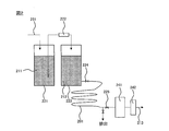
- FIG. 2 is a diagram for explaining a method for measuring the number of particles.
- nitrogen gas 231 is supplied into the first chemical liquid container 221, and the isopropyl alcohol (IPA) 211 stored in the chemical liquid container 221 is pressurized.
- the pressurized IPA 211 passes through the filter 222 and is stored in the second chemical liquid container 223.
- the IPA 212 in the second chemical liquid container 223 is used for measurement after being left for 1 day.
- a valve 224 is connected to the lower portion of the second chemical liquid container 223, and the evaluation tube 201 is connected to the second chemical liquid container 223 via the valve 224.
- the other end of the evaluation tube 201 is connected to the particle counter 241 via the valve 225.
- a syringe pump 242 is provided on the downstream side of the particle counter 241 so that the IPA in the evaluation tube 201 can be introduced into the particle counter 241.
- valves 224 and 225 it is necessary to use diaphragm valves as the valves 224 and 225 in order to prevent particles from mixing into the IPA 212 by opening and closing the valves 224 and 225 connected to the evaluation tube 201.
- the IPA 212 is supplied from the second chemical liquid container 223 to the evaluation tube 201, and the IPA is sealed in the evaluation tube 201.
- the syringe pump 242 is operated to introduce the IPA in the evaluation tube 201 into the particle counter 241.
- the number of particles is measured in this way.
- Both PFA1 and PFA2 are commercially available tubes. From the results of Comparative Examples 1 and 2, it was found that a maximum of tens of thousands of particles/ml were observed from the commercially available PFA tube. In addition, since the number of particles is different between Comparative Examples 1 and 2, it was estimated that there was a difference in the degree of contamination depending on the type of tube and the history after molding. In addition, even when the amount of IPA that is more than about 16 times the internal volume has been passed through and measured, PFA1 measures 186 particles/ml and PFA2 measures significantly more than 1000 particles/ml. Was done.
- Comparative Example 3 PFA1 having an outer diameter of 6 mm and an inner diameter of 4 mm was cut into a length of 5 m to prepare a tube for evaluation. After washing the tube by passing ultrapure water (UPW) in an amount about 20 times the volume of the tube, the number of particles was measured according to the method described above. The results are shown in Table 1.
- UHP ultrapure water
- Comparative Example 4 The number of particles was measured in the same manner as in Comparative Example 3 except that PFA2 having an outer diameter of 6 mm and an inner diameter of 4 mm was used. The results are shown in Table 1.
- Comparative Example 5 PFA1 having an outer diameter of 6 mm and an inner diameter of 4 mm was cut into a length of 5 m to prepare a tube for evaluation. After washing the tube by passing IPA in an amount about 20 times the volume of the tube, the number of particles was measured according to the method described above. The results are shown in Table 1.
- Comparative Example 6 The number of particles was measured in the same manner as in Comparative Example 5 except that PFA2 having an outer diameter of 6 mm and an inner diameter of 4 mm was used. The results are shown in Table 1.
- Example 1 PFA1 having an outer diameter of 6 mm and an inner diameter of 4 mm was cut into a length of 5 m to prepare a tube for evaluation.
- the tube was washed by passing ultrapure water (UPW) in an amount about 20 times the volume of the tube, and then by passing the same amount of IPA in order to wash the particles. The number was measured. The results are shown in Table 1.
- UPF ultrapure water
- Example 2 The number of particles was measured in the same manner as in Example 1 except that PFA2 having an outer diameter of 6 mm and an inner diameter of 4 mm was used. The results are shown in Table 1.
- Example 3 PFA1 having an outer diameter of 6 mm and an inner diameter of 4 mm was cut into a length of 5 m to prepare a tube for evaluation.
- the tube was washed by passing approximately 20 times the volume of the IPA in the tube, and then by passing the same amount of ultrapure water (UPW) to wash the particles. The number was measured. The results are shown in Table 1.
- Example 4 The number of particles was measured in the same manner as in Example 3 except that an IPA aqueous solution (IPA concentration was 60% by mass) was used instead of IPA. The results are shown in Table 1.
- Example 5 The number of particles was measured in the same manner as in Example 3 except that an IPA aqueous solution (IPA concentration was 30% by mass) was used instead of IPA. The results are shown in Table 1.
Landscapes
- Chemical & Material Sciences (AREA)
- Chemical Kinetics & Catalysis (AREA)
- Organic Chemistry (AREA)
- Health & Medical Sciences (AREA)
- Medicinal Chemistry (AREA)
- Polymers & Plastics (AREA)
- Engineering & Computer Science (AREA)
- Wood Science & Technology (AREA)
- Life Sciences & Earth Sciences (AREA)
- Oil, Petroleum & Natural Gas (AREA)
- Mechanical Engineering (AREA)
- Emergency Medicine (AREA)
- Inorganic Chemistry (AREA)
- Addition Polymer Or Copolymer, Post-Treatments, Or Chemical Modifications (AREA)
- Cleaning In General (AREA)
- Cleaning By Liquid Or Steam (AREA)
- Treatments Of Macromolecular Shaped Articles (AREA)
- Cleaning Or Drying Semiconductors (AREA)
- Manufacture Of Macromolecular Shaped Articles (AREA)
- Processing And Handling Of Plastics And Other Materials For Molding In General (AREA)
Abstract
Description
本開示の製造方法において、前記薬液が、アルコール濃度が20~100質量%のアルコールまたはアルコール水溶液であることがより好ましい。
本開示の製造方法において、前記薬液が、pH8以上のアルカリ性水溶液であることが好ましい。
本開示の製造方法において、前記薬液が、アンモニア水溶液であることが好ましい。
本開示の製造方法において、薬液による洗浄が、流液洗浄であることが好ましい。
本開示の製造方法において、水による洗浄が、流水洗浄であることが好ましい。
本開示の製造方法において、前記フッ素樹脂成形品が、フッ素樹脂として、テトラフルオロエチレン/パーフルオロ(アルキルビニルエーテル)共重合体を含有することが好ましい。
本開示の製造方法において、前記フッ素樹脂成形品が、チューブであることが好ましい。
本開示の製造方法は、洗浄に用いた前記薬液からパーティクルを除去する工程、および、パーティクルを除去した前記薬液を、薬液により洗浄する工程で用いる薬液の少なくとも一部として再利用する工程をさらに含むことが好ましい。
本開示の製造方法は、洗浄に用いた前記水からパーティクルを除去する工程、および、パーティクルを除去した前記水を、水により洗浄する工程で用いる水の少なくとも一部として再利用する工程をさらに含むことが好ましい。
無機系物質には、金属酸化物、非金属酸化物または塩類が含まれ、これらは、主に、水による洗浄工程を実施することによって、フッ素樹脂成形品の表面から除去される。
一方、有機系物質には、フッ素樹脂の成形雰囲気下に存在する可塑剤に由来する成分や、空気中に浮遊しているカーボン類、フッ素樹脂材料由来のパーティクルなどが含まれる。これらのうち、特にフッ素樹脂材料に由来するパーティクル(フッ素系パーティクル)は、水による洗浄工程において除去することが困難であり、薬液による洗浄工程において除去することが好ましい。なお、フッ素系パーティクルとは、炭素原子およびフッ素原子を含むパーティクルである。
そこで、本開示の製造方法における薬液による洗浄工程では、フッ素樹脂成形品に特有のパーティクルであって、水による洗浄が困難なフッ素系パーティクルを容易に除去できる薬液を用いることが好ましい。
CH2=CX5Rf3、CF2=CFRf3、CF2=CFORf3、CH2=C(Rf3)2
(式中、X5はHまたはF、Rf3はエーテル結合を含んでいてもよいフルオロアルキル基を表す。)で表される単量体が挙げられ、なかでも、CF2=CFRf3、CF2=CFORf3およびCH2=CX5Rf3で表される含フッ素ビニルモノマーが好ましく、HFP、CF2=CF-ORf4(式中、Rf4は炭素数1~5のパーフルオロアルキル基を表す。)で表されるパーフルオロ(アルキルビニルエーテル)およびRf3が炭素数1~8のフルオロアルキル基であるCH2=CX5Rf3で表される含フッ素ビニルモノマーがより好ましい。また、TFEおよびエチレンと共重合可能な単量体としては、イタコン酸、無水イタコン酸等の脂肪族不飽和カルボン酸であってもよい。上記ETFEは、TFEおよびエチレンと共重合可能な単量体単位が、0.1~10モル%であることが好ましく、0.1~5モル%であることがより好ましく、0.2~4モル%であることが特に好ましい。
ダイヤフラムポンプの隔膜部、ベローズ成形品、電線被覆品、半導体用部品、パッキン・シール、コピーロール用薄肉チューブ、モノフィラメント、ベルト、ガスケット、光学レンズ部品、石油発掘用チューブ、地熱発電用チューブ、石油発掘用電線、サテライト用電線、原子力発電用電線、航空機用電線、太陽電池パネルフィルム、二次電池や電気二重層コンデンサーなどのガスケット、OAロール等;
ガスや薬液を流通させるためのチューブ、薬品を保管するためのボトル、ガスバック、薬液バック、薬液容器、冷凍保存用バック等;
開閉バルブのボディーや部品類、継手とチューブを接続する際に使用されるスリーブ類、薬液ボトルや容器のスクリューキャップ類、またギア類、ネジ類、フライパン、鍋、炊飯ジャー、金属など基盤上にフッ素樹脂を被覆された製品類、離形フィルム等;
a.基盤となるシリコンウェハを洗浄する「洗浄工程」
b.シリコンウェハ上に回路素材となる薄膜を形成する「成膜工程」
c.フォトレジスト(感光液)を均一に塗布する「レジスト塗布工程」
d.回路パターンの転写を行う「露光工程」
e.露光された部分のフォトレジストを溶かす「現像工程」
f.薬液やイオンにより露出した下地の薄膜を除去する「エッチング工程」
g.リンなど不純物を注入し、シリコンに電気的特性を持たせる「イオン注入工程」
h.不要なフォトレジストを除去する「剥離工程」、
実施例および比較例で用いたチューブから試料を作製し、示差走査熱量計〔DSC〕を用いて10℃/分の速度で昇温したときの融解熱曲線における極大値に対応する温度として求めた。
実施例および比較例で用いたチューブから試料を作製し、ASTM D1238に従って、メルトインデクサー(安田精機製作所社製)を用いて、372℃、5kg荷重下で内径2mm、長さ8mmのノズルから10分間あたりに流出するポリマーの質量(g/10分)を求めた。
実施例および比較例で用いたチューブから試料を作製し、19F-NMR法により測定した。
(1)イソプロピルアルコールの調製
5nmφのフィルターを用いて、市販の高純度イソプロピルアルコール(IPA)を濾過した。濾過したIPAを、1日間放置して、30nmφサイズ以上のパーティクル数が、30個/ml以下であることを確認した。チューブの洗浄およびパーティクル数の測定には、このようにして濾過したIPAを用いた。
実施例および比較例で作製した評価用のチューブを、図2に示すパーティクルカウンターに接続し、測定に用いるIPAでチューブを満たした。次に、シリンジポンプを用いて、チューブ中のIPAを、パーティクルカウンター(リオン社製、光散乱式液中粒子検出器KS-19F)に導入して、パーティクル数を測定した。
外径6mm、内径4mmのPFA(TFE/パーフルオロ(プロピルビニルエーテル)〔PPVE〕共重合体[TFE/PPVE=96.5/3.5(質量%)]、MFR2.5g/10分、融点306℃)のチューブ(以下、「PFA1」という)を、長さ5mにカットして、評価用のチューブを作製した。このチューブを一切洗浄することなく用いて、上記した方法にしたがって、パーティクル数を測定した。結果を表1に示す。
外径6mm、内径4mmのPFA(TFE/PPVE共重合体[TFE/PPVE=94.5/5.5(質量%)]、MFR3.2g/10分、融点302℃)のチューブ(以下、「PFA2」という)を用いた以外は、比較例1と同様にして、パーティクル数を測定した。結果を表1に示す。
外径6mm、内径4mmのPFA1を、長さ5mにカットして、評価用のチューブを作製した。このチューブに、チューブ内容量の約20倍量の超純水(UPW)を通液することにより洗浄した後、上記した方法にしたがって、パーティクル数を測定した。結果を表1に示す。
外径6mm、内径4mmのPFA2を用いた以外は、比較例3と同様にして、パーティクル数を測定した。結果を表1に示す。
外径6mm、内径4mmのPFA1を、長さ5mにカットして、評価用のチューブを作製した。このチューブに、チューブ内容量の約20倍量のIPAを通液することにより洗浄した後、上記した方法にしたがって、パーティクル数を測定した。結果を表1に示す。
外径6mm、内径4mmのPFA2を用いた以外は、比較例5と同様にして、パーティクル数を測定した。結果を表1に示す。
外径6mm、内径4mmのPFA1を、長さ5mにカットして、評価用のチューブを作製した。このチューブに、チューブ内容量の約20倍量の超純水(UPW)を通液することにより洗浄し、さらに同量のIPAを通液することにより洗浄した後、上記した方法にしたがって、パーティクル数を測定した。結果を表1に示す。
外径6mm、内径4mmのPFA2を用いた以外は、実施例1と同様にして、パーティクル数を測定した。結果を表1に示す。
外径6mm、内径4mmのPFA1を、長さ5mにカットして、評価用のチューブを作製した。このチューブに、チューブ内容量の約20倍量のIPAを通液することにより洗浄し、さらに同量の超純水(UPW)を通液することにより洗浄した後、上記した方法にしたがって、パーティクル数を測定した。結果を表1に示す。
IPAの代わりに、IPA水溶液(IPA濃度が60質量%)を用いた以外は、実施例3と同様にして、パーティクル数を測定した。結果を表1に示す。
IPAの代わりに、IPA水溶液(IPA濃度が30質量%)を用いた以外は、実施例3と同様にして、パーティクル数を測定した。結果を表1に示す。

11 フィルター
12 薬液容器
13 ポンプ
14 バルブ
21 フィルター
22 水容器
23 ポンプ
24 バルブ
31 切替バルブ
32 洗浄部材接続配管系
41 バルブ
Claims (12)
- フッ素樹脂成形品を薬液により洗浄する工程、および、フッ素樹脂成形品を水により洗浄する工程を含む、洗浄されたフッ素樹脂成形品の製造方法。
- 前記薬液が、アルコールまたはアルコール水溶液である請求項1に記載の製造方法。
- 前記薬液が、アルコール濃度が20~100質量%のアルコールまたはアルコール水溶液である請求項1または2に記載の製造方法。
- 前記薬液が、pH8以上のアルカリ性水溶液である請求項1に記載の製造方法。
- 前記薬液が、アンモニア水溶液である請求項1または4に記載の製造方法。
- 薬液による洗浄が、流液洗浄である請求項1~5のいずれかに記載の製造方法。
- 水による洗浄が、流水洗浄である請求項1~6のいずれかに記載の製造方法。
- 前記フッ素樹脂成形品が、フッ素樹脂として、テトラフルオロエチレン/パーフルオロ(アルキルビニルエーテル)共重合体を含有する請求項1~7のいずれかに記載の製造方法。
- 前記フッ素樹脂成形品が、チューブである請求項1~8のいずれかに記載の製造方法。
- 洗浄に用いた前記薬液からパーティクルを除去する工程、および、パーティクルを除去した前記薬液を、薬液により洗浄する工程で用いる薬液の少なくとも一部として再利用する工程をさらに含む請求項1~9のいずれか記載の製造方法。
- 洗浄に用いた前記水からパーティクルを除去する工程、および、パーティクルを除去した前記水を、水により洗浄する工程で用いる水の少なくとも一部として再利用する工程をさらに含む請求項1~10のいずれかに記載の製造方法。
- 洗浄されたフッ素樹脂成形品を製造する製造システムであって、
薬液からパーティクルを除去するための第1の濾過手段と、
水からパーティクルを除去するための第2の濾過手段と、
第1の濾過手段から薬液が供給され、第2の濾過手段から水が供給されるフッ素樹脂成形品の洗浄手段と、
第1の濾過手段から洗浄手段への薬液の供給と、第2の濾過手段から洗浄手段への水の供給とを切り替えるための切替手段と、
洗浄に用いた薬液を洗浄手段から第1の濾過手段に戻すための第1の返送手段と、
洗浄に用いた水を洗浄手段から第2の濾過手段に戻すための第2の返送手段と、
を備える製造システム。
Priority Applications (3)
| Application Number | Priority Date | Filing Date | Title |
|---|---|---|---|
| CN201980076801.7A CN113166455B (zh) | 2018-11-27 | 2019-11-26 | 氟树脂成型品的制造方法和制造系统 |
| US17/296,775 US12311417B2 (en) | 2018-11-27 | 2019-11-26 | Method and system for producing fluororesin molded article |
| KR1020217015551A KR102504511B1 (ko) | 2018-11-27 | 2019-11-26 | 불소 수지 성형품의 제조 방법 및 제조 시스템 |
Applications Claiming Priority (2)
| Application Number | Priority Date | Filing Date | Title |
|---|---|---|---|
| JP2018220928 | 2018-11-27 | ||
| JP2018-220928 | 2018-11-27 |
Publications (1)
| Publication Number | Publication Date |
|---|---|
| WO2020111066A1 true WO2020111066A1 (ja) | 2020-06-04 |
Family
ID=70853981
Family Applications (1)
| Application Number | Title | Priority Date | Filing Date |
|---|---|---|---|
| PCT/JP2019/046187 Ceased WO2020111066A1 (ja) | 2018-11-27 | 2019-11-26 | フッ素樹脂成形品の製造方法および製造システム |
Country Status (6)
| Country | Link |
|---|---|
| US (1) | US12311417B2 (ja) |
| JP (1) | JP6870721B2 (ja) |
| KR (1) | KR102504511B1 (ja) |
| CN (1) | CN113166455B (ja) |
| TW (1) | TWI778309B (ja) |
| WO (1) | WO2020111066A1 (ja) |
Cited By (2)
| Publication number | Priority date | Publication date | Assignee | Title |
|---|---|---|---|---|
| JP2022028402A (ja) * | 2020-08-03 | 2022-02-16 | 三井・ケマーズ フロロプロダクツ株式会社 | 樹脂ペレット及びその成形品 |
| JP7428950B1 (ja) | 2022-09-09 | 2024-02-07 | ダイキン工業株式会社 | フッ素樹脂チューブから発生するパーティクル数の測定方法 |
Families Citing this family (2)
| Publication number | Priority date | Publication date | Assignee | Title |
|---|---|---|---|---|
| JP7840724B2 (ja) * | 2022-02-25 | 2026-04-06 | 株式会社Screenホールディングス | 基板処理液の精製方法および精製装置 |
| JP7846570B2 (ja) * | 2022-06-14 | 2026-04-15 | 株式会社Screenホールディングス | 洗浄時間算出方法 |
Citations (8)
| Publication number | Priority date | Publication date | Assignee | Title |
|---|---|---|---|---|
| JPS63258936A (ja) * | 1987-04-16 | 1988-10-26 | Bridgestone Corp | 導電性高分子膜の製造方法 |
| JPH03112632A (ja) * | 1989-09-26 | 1991-05-14 | Daikin Ind Ltd | フッ素樹脂製品の処理方法 |
| JPH04175350A (ja) * | 1990-07-04 | 1992-06-23 | Piyuaretsukusu:Kk | プラスチック成形品表面の清浄化処理方法 |
| JPH05160096A (ja) * | 1991-12-04 | 1993-06-25 | U M S:Kk | 誘電体表面の除塵及び帯電防止方法 |
| JPH10195212A (ja) * | 1997-01-16 | 1998-07-28 | Tokuyama Corp | フッ素樹脂成形体の製造方法 |
| JP2006071262A (ja) * | 2004-08-05 | 2006-03-16 | Matsushita Electric Ind Co Ltd | 液体加熱装置、洗浄装置、および洗浄方法 |
| JP2018022056A (ja) * | 2016-08-04 | 2018-02-08 | キヤノン株式会社 | 撥液膜とその製造方法、定着部材、定着装置及び画像形成装置 |
| WO2020004083A1 (ja) * | 2018-06-26 | 2020-01-02 | ダイキン工業株式会社 | 成形品およびその製造方法 |
Family Cites Families (24)
| Publication number | Priority date | Publication date | Assignee | Title |
|---|---|---|---|---|
| GB1206662A (en) * | 1968-04-16 | 1970-09-30 | Ici Ltd | Solvent composition for cleaning |
| US4430283A (en) * | 1980-11-13 | 1984-02-07 | The Dow Chemical Company | Method for the extrusion of tetrafluoroethylene polymer tubes |
| FR2612695A1 (fr) | 1987-03-18 | 1988-09-23 | Bridgestone Corp | Pile secondaire non aqueuse |
| US4904553A (en) | 1987-04-16 | 1990-02-27 | Bridgestone Corporation | Polyaniline |
| JP3275431B2 (ja) * | 1993-03-25 | 2002-04-15 | ダイキン工業株式会社 | フッ素樹脂成形体およびその製法 |
| JPH07157514A (ja) * | 1993-12-03 | 1995-06-20 | Gunze Ltd | フッ素系樹脂又はその成形体の改質方法乃び複合成形物中間材料 |
| JPH0887374A (ja) * | 1994-09-16 | 1996-04-02 | Toshiba Corp | 入力装置 |
| US6663722B1 (en) * | 1998-03-25 | 2003-12-16 | Daikin Industries, Ltd. | Method of cleaning fluorine-containing rubber molded article for semiconductor production apparatuses and cleaned molded article |
| JP2001004895A (ja) * | 1999-06-23 | 2001-01-12 | Olympus Optical Co Ltd | 鏡 枠 |
| JP4792622B2 (ja) * | 2000-05-30 | 2011-10-12 | 旭硝子株式会社 | テトラフルオロエチレン/パーフルオロ(アルキルビニルエーテル)共重合体及びその製造方法 |
| US20030226214A1 (en) * | 2002-05-02 | 2003-12-11 | The Procter & Gamble Company | Cleaning system containing a solvent filtration device and method for using the same |
| KR20060048607A (ko) | 2004-08-05 | 2006-05-18 | 마츠시타 덴끼 산교 가부시키가이샤 | 액체가열장치, 세정장치, 및 세정방법 |
| WO2007046377A1 (ja) * | 2005-10-20 | 2007-04-26 | Asahi Glass Company, Limited | 溶融成形可能なフッ素樹脂の製造方法 |
| US20070240740A1 (en) * | 2006-04-13 | 2007-10-18 | Mcdermott Wayne T | Cleaning of contaminated articles by aqueous supercritical oxidation |
| US7578889B2 (en) * | 2007-03-30 | 2009-08-25 | Lam Research Corporation | Methodology for cleaning of surface metal contamination from electrode assemblies |
| JP5797449B2 (ja) | 2010-05-13 | 2015-10-21 | 株式会社半導体エネルギー研究所 | 半導体装置の評価方法 |
| JP5692167B2 (ja) * | 2012-06-05 | 2015-04-01 | 株式会社デンソー | 被処理物から汚れ物質を洗浄し、除去する方法及び装置 |
| JP5454726B2 (ja) * | 2012-07-05 | 2014-03-26 | ダイキン工業株式会社 | 改質含フッ素共重合体、フッ素樹脂成形品、及び、フッ素樹脂成形品の製造方法 |
| JP2015040279A (ja) | 2013-08-23 | 2015-03-02 | 三井・デュポンフロロケミカル株式会社 | 半導体製造装置に用いられるフッ素樹脂成形品の洗浄方法 |
| JP5697781B1 (ja) * | 2014-05-26 | 2015-04-08 | 日本バルカー工業株式会社 | 弁体の製造方法 |
| CN105082495B (zh) * | 2015-07-07 | 2019-07-05 | 上海交通大学 | 一种氟树脂复合物的制造方法,氟树脂复合物及其制品成形 |
| WO2018034238A1 (ja) * | 2016-08-16 | 2018-02-22 | ダイキン工業株式会社 | 成形品及び成形品の製造方法 |
| JP2019034544A (ja) * | 2017-08-21 | 2019-03-07 | ダイキン工業株式会社 | 積層体、成形品、及び、インタンクチューブ |
| JP6936274B2 (ja) * | 2018-06-26 | 2021-09-15 | ダイキン工業株式会社 | 成形品およびその製造方法 |
-
2019
- 2019-11-26 JP JP2019213072A patent/JP6870721B2/ja active Active
- 2019-11-26 WO PCT/JP2019/046187 patent/WO2020111066A1/ja not_active Ceased
- 2019-11-26 CN CN201980076801.7A patent/CN113166455B/zh active Active
- 2019-11-26 US US17/296,775 patent/US12311417B2/en active Active
- 2019-11-26 KR KR1020217015551A patent/KR102504511B1/ko active Active
- 2019-11-27 TW TW108143152A patent/TWI778309B/zh active
Patent Citations (8)
| Publication number | Priority date | Publication date | Assignee | Title |
|---|---|---|---|---|
| JPS63258936A (ja) * | 1987-04-16 | 1988-10-26 | Bridgestone Corp | 導電性高分子膜の製造方法 |
| JPH03112632A (ja) * | 1989-09-26 | 1991-05-14 | Daikin Ind Ltd | フッ素樹脂製品の処理方法 |
| JPH04175350A (ja) * | 1990-07-04 | 1992-06-23 | Piyuaretsukusu:Kk | プラスチック成形品表面の清浄化処理方法 |
| JPH05160096A (ja) * | 1991-12-04 | 1993-06-25 | U M S:Kk | 誘電体表面の除塵及び帯電防止方法 |
| JPH10195212A (ja) * | 1997-01-16 | 1998-07-28 | Tokuyama Corp | フッ素樹脂成形体の製造方法 |
| JP2006071262A (ja) * | 2004-08-05 | 2006-03-16 | Matsushita Electric Ind Co Ltd | 液体加熱装置、洗浄装置、および洗浄方法 |
| JP2018022056A (ja) * | 2016-08-04 | 2018-02-08 | キヤノン株式会社 | 撥液膜とその製造方法、定着部材、定着装置及び画像形成装置 |
| WO2020004083A1 (ja) * | 2018-06-26 | 2020-01-02 | ダイキン工業株式会社 | 成形品およびその製造方法 |
Cited By (5)
| Publication number | Priority date | Publication date | Assignee | Title |
|---|---|---|---|---|
| JP2022028402A (ja) * | 2020-08-03 | 2022-02-16 | 三井・ケマーズ フロロプロダクツ株式会社 | 樹脂ペレット及びその成形品 |
| JP7643843B2 (ja) | 2020-08-03 | 2025-03-11 | 三井・ケマーズ フロロプロダクツ株式会社 | 樹脂ペレット及びその成形品 |
| JP7428950B1 (ja) | 2022-09-09 | 2024-02-07 | ダイキン工業株式会社 | フッ素樹脂チューブから発生するパーティクル数の測定方法 |
| WO2024053706A1 (ja) * | 2022-09-09 | 2024-03-14 | ダイキン工業株式会社 | フッ素樹脂チューブから発生するパーティクル数の測定方法 |
| JP2024039637A (ja) * | 2022-09-09 | 2024-03-22 | ダイキン工業株式会社 | フッ素樹脂チューブから発生するパーティクル数の測定方法 |
Also Published As
| Publication number | Publication date |
|---|---|
| TW202037657A (zh) | 2020-10-16 |
| JP6870721B2 (ja) | 2021-05-12 |
| KR102504511B1 (ko) | 2023-02-28 |
| US12311417B2 (en) | 2025-05-27 |
| JP2020090666A (ja) | 2020-06-11 |
| KR20210080501A (ko) | 2021-06-30 |
| CN113166455B (zh) | 2023-05-23 |
| US20220088648A1 (en) | 2022-03-24 |
| CN113166455A (zh) | 2021-07-23 |
| TWI778309B (zh) | 2022-09-21 |
Similar Documents
| Publication | Publication Date | Title |
|---|---|---|
| KR102620420B1 (ko) | 용착체 | |
| JP7557155B2 (ja) | 成形品の製造方法および成形品 | |
| JP6870721B2 (ja) | フッ素樹脂成形品の製造方法および製造システム | |
| KR102458474B1 (ko) | 성형품 및 그 제조 방법 | |
| US12036714B2 (en) | Molding material and tube | |
| JP4386077B2 (ja) | 半導体製造装置用のフッ素ゴム系成形品の洗浄方法および洗浄された成形品 | |
| CN103635517A (zh) | 氟树脂颗粒的处理方法 | |
| TWI888611B (zh) | 樹脂丸粒及其模製產品 | |
| JP2024039637A (ja) | フッ素樹脂チューブから発生するパーティクル数の測定方法 |
Legal Events
| Date | Code | Title | Description |
|---|---|---|---|
| 121 | Ep: the epo has been informed by wipo that ep was designated in this application |
Ref document number: 19890897 Country of ref document: EP Kind code of ref document: A1 |
|
| ENP | Entry into the national phase |
Ref document number: 20217015551 Country of ref document: KR Kind code of ref document: A |
|
| NENP | Non-entry into the national phase |
Ref country code: DE |
|
| 122 | Ep: pct application non-entry in european phase |
Ref document number: 19890897 Country of ref document: EP Kind code of ref document: A1 |
|
| WWG | Wipo information: grant in national office |
Ref document number: 17296775 Country of ref document: US |