WO2020111024A1 - キャップ付き容器、二重容器のリーク検査方法、積層剥離容器及びその製造方法 - Google Patents
キャップ付き容器、二重容器のリーク検査方法、積層剥離容器及びその製造方法 Download PDFInfo
- Publication number
- WO2020111024A1 WO2020111024A1 PCT/JP2019/046063 JP2019046063W WO2020111024A1 WO 2020111024 A1 WO2020111024 A1 WO 2020111024A1 JP 2019046063 W JP2019046063 W JP 2019046063W WO 2020111024 A1 WO2020111024 A1 WO 2020111024A1
- Authority
- WO
- WIPO (PCT)
- Prior art keywords
- container
- inner bag
- cap
- laminated
- outer shell
- Prior art date
Links
Images


Classifications
-
- B—PERFORMING OPERATIONS; TRANSPORTING
- B65—CONVEYING; PACKING; STORING; HANDLING THIN OR FILAMENTARY MATERIAL
- B65D—CONTAINERS FOR STORAGE OR TRANSPORT OF ARTICLES OR MATERIALS, e.g. BAGS, BARRELS, BOTTLES, BOXES, CANS, CARTONS, CRATES, DRUMS, JARS, TANKS, HOPPERS, FORWARDING CONTAINERS; ACCESSORIES, CLOSURES, OR FITTINGS THEREFOR; PACKAGING ELEMENTS; PACKAGES
- B65D1/00—Containers having bodies formed in one piece, e.g. by casting metallic material, by moulding plastics, by blowing vitreous material, by throwing ceramic material, by moulding pulped fibrous material, by deep-drawing operations performed on sheet material
- B65D1/02—Bottles or similar containers with necks or like restricted apertures, designed for pouring contents
-
- B—PERFORMING OPERATIONS; TRANSPORTING
- B65—CONVEYING; PACKING; STORING; HANDLING THIN OR FILAMENTARY MATERIAL
- B65D—CONTAINERS FOR STORAGE OR TRANSPORT OF ARTICLES OR MATERIALS, e.g. BAGS, BARRELS, BOTTLES, BOXES, CANS, CARTONS, CRATES, DRUMS, JARS, TANKS, HOPPERS, FORWARDING CONTAINERS; ACCESSORIES, CLOSURES, OR FITTINGS THEREFOR; PACKAGING ELEMENTS; PACKAGES
- B65D41/00—Caps, e.g. crown caps or crown seals, i.e. members having parts arranged for engagement with the external periphery of a neck or wall defining a pouring opening or discharge aperture; Protective cap-like covers for closure members, e.g. decorative covers of metal foil or paper
- B65D41/02—Caps or cap-like covers without lines of weakness, tearing strips, tags, or like opening or removal devices
- B65D41/04—Threaded or like caps or cap-like covers secured by rotation
Definitions
- the present invention relates to a container with a cap, a leak inspection method for a double container, a laminated peeling container, and a manufacturing method thereof.
- Patent Literature 1 discloses a cap provided with a riding portion (projection) at the terminal end portion of the thread of the male screw portion as a loosening stopper when the cap is tightened by screwing. With this configuration, it is possible to grasp the end point at the time of tightening by the click feeling when the projection provided on the lower surface of the cap exceeds the riding portion.
- Patent Document 2 air is supplied into the inner bag, and the presence or absence of perforation in the inner bag is inspected based on whether or not the pressure in the inner bag reaches a predetermined value after a lapse of a predetermined time.
- the present invention has been made in view of such circumstances and provides a container with a cap capable of preventing overrun of the cap.
- the present invention has been made in view of such circumstances, and provides a leak inspection method capable of detecting whether or not there is a pinhole in the inner bag of a double container.
- a pinch-off part (seal part) when one end of the laminated parison is welded is provided at the bottom of the laminated peeling container as shown in Patent Document 3, but the inner bag is detached from the bottom at this pinch-off part. There is. If the inner bag is detached from the bottom with the contents remaining in the inner bag, the contraction of the inner bag cannot be regulated, which may block the flow path or lead to pinholes. There is.
- the welding layers in the pinch-off portion are adhered to each other by a plurality of biting portions so as to be engaged with each other.
- the mold structure becomes complicated. , Leading to an increase in production costs. Further, in such a configuration, there is also a problem that the pinch-off portion cannot be provided with an outside air introduction portion for introducing outside air between the outer shell and the inner bag.
- the present invention has been made in view of such circumstances, and provides a laminated peeling container in which the detachment of the inner bag from the bottom is limited.
- a cap-equipped container having a container body and a cap, wherein the cap has a female screw portion, and the container body has a male screw portion that is screwed into the female screw portion at its mouth.
- the cap includes a protrusion at a position closer to the container body than the female screw portion, and the container body engages with the protrusion to restrict a loosening of the cap, and a screw is tightened more than the riding part.
- a container with a cap which is provided on the side of the direction and has a stopper portion for restricting the overrun of the cap.
- the container body is provided with the stopper portion on the screw fastening direction side with respect to the riding portion, it is possible to prevent the overrun of the cap.
- At least one of the height of the stopper portion and the radial width of the stopper portion is made larger than that of the riding portion.
- the protrusions are provided at two locations facing each other in the circumferential direction, and the riding portion and the stopper portion are also provided at two locations facing each other in the circumferential direction.
- the height of the stopper part that regulates the overrun of one protrusion is approximately the maximum height that does not interfere with the other protrusion.
- the stopper portion has a tapered surface on the fastening direction side of the screw in the circumferential direction to prevent interference with the other protrusion.
- the container body has an outer shell and an inner bag and is configured such that the inner bag shrinks as the content decreases.
- an air introducing hole is formed in the outer shell, and the riding portion and the stopper portion are provided at substantially the same position in the circumferential direction as the air introducing hole or at a position facing each other in the circumferential direction.
- a double-container leak inspection method wherein the double-container has an outer shell and an inner bag, and is configured such that the inner bag shrinks as the content decreases.
- the method is provided with the step of determining whether or not there is a pinhole in the inner bag based on data obtained when decompressing the inside of the inner bag.
- Data such as the flow rate of air sucked out from the inside of the inner bag when depressurizing the inner bag and the pressure of depressurization differ depending on whether there are pinholes in the inner bag. Based on this difference, it can be determined whether or not there is a pinhole in the inner bag.
- the method is the method described above, wherein the determination is performed based on a flow rate of air sucked from the inner bag during the depressurization.
- the depressurization is performed in a state where a rod-shaped portion is inserted into the inner bag from the mouth of the double container.
- it is a method of pre-peeling a double container, wherein the double container has an outer shell and an inner bag, and is configured such that the inner bag shrinks as the content decreases.
- the method comprises a step of peeling the inner bag from the outer shell by depressurizing the inside of the inner bag with the rod-shaped portion inserted into the inner bag from the mouth of the double container. is there.
- L/H is 0. .40 or more.
- D1 and the circumscribed circle diameter of the rod-shaped portion are D2 and D2/D1 are 0.30 or more. , Is the way.
- the method described above is the method in which the depressurization is performed through a suction port provided in the rod-shaped portion.
- it is the method described above, wherein the suction port is provided at the tip of the rod-shaped portion.
- a laminated peeling container having an outer shell and an inner bag and in which the inner bag shrinks as the content decreases, a container for containing the content, and a bottom of the container.
- a pinch-off portion formed in, the end portion in the longitudinal direction of the pinch-off portion, an engaging portion for engaging the outer shell and the inner bag, the inner bag, in the engaging portion, A protrusion protruding outward in the longitudinal direction is provided, and the outer shell is provided with a recess that engages with the protrusion in the engaging portion, and the protrusion amount of the protrusion in the longitudinal direction is the bottom portion.
- a laminated peeling container having a length in the longitudinal direction from the center of 0.1 to 0.15 times or more the length in the longitudinal direction.
- the engagement portion is provided at the longitudinal end portion of the pinch-off portion, and the protrusion portion of the inner bag and the recess portion of the outer shell are engaged with each other at the engagement portion, thereby limiting the detachment of the inner bag. It is possible to do.
- the tip of the convex portion projects to a position substantially the same as the edge of the bottom surface of the inner bag in the radial direction, or projects outward from the edge of the bottom surface of the inner bag.
- the pinch-off portion is provided with an outside air introduction hole for introducing outside air into the space between the outer shell and the inner bag.
- a method for producing a laminated peeling container which has an outer shell and an inner bag, and in which the inner bag shrinks as the content decreases, a blow using a cylindrical laminated parison.
- a molding step is provided, and the mold has a compression part near the biting part that molds the pinch-off part of the laminated peeling container, and a compression part that compresses the laminated parison before mold clamping to cause the laminated parison to flow in the container inward direction.
- the compression section includes a first compression area formed at a position near both ends in the longitudinal direction of the bite cut section, and a second compression area formed at a position between the first compression areas.
- a method for manufacturing a laminated peeling container wherein a width of the first compression region during mold clamping is narrower than a width of the second compression region during mold clamping.
- the diameter of the die for extruding the laminated parison is not more than 2/ ⁇ times the inner diameter of the portion forming the bottom of the inner diameter of the mold.
- the width of the first compression region at the time of mold clamping is not more than the wall thickness of the laminated parison, and the width of the second compression region at the time of mold clamping is not more than twice the wall thickness of the laminated parison. is there.
- the second compression region has a width of 5 mm or less when the mold is clamped.
- FIG. 4A is an enlarged plan view of an essential part of the container body 2 of FIG. 1
- FIG. 6B is an enlarged front view of an essential part of the container body 2 of FIG.
- FIG. 9 is an exploded perspective view showing the configuration of the head 103 of FIG. 8.
- FIG. 10 is a cross-sectional view showing a state in which the head 103 of FIG. 9 is brought into contact with the end surface of the mouth 109 of the double container 101.
- FIG. 11 is a cross-sectional view showing a state after the inner bag 114 is decompressed from the state of FIG. 10 to shrink the inner bag 114.
- 7 is a graph showing the relationship between time and flow rate, which is measured during depressurization inside the inner bag 114.
- FIG. 14 is a cross-sectional view showing a state in which the head 103 of FIG. 13 is brought into contact with the end surface of the mouth 109 of the double container 101. It is sectional drawing which shows the state after decompressing the inside of the inner bag 114 from the state of FIG. 14, and making the inner bag 114 shrink.
- FIG. 12 is a cross-sectional view corresponding to FIG. 11 when the inner bag 114 is unevenly peeled.
- FIG. 18A is a perspective view of a laminate peeling container 201 according to an embodiment of the third aspect of the present invention
- FIG. 18B is a perspective view showing a bottom portion 232 of the laminate peeling container 201 of FIG. 18A.
- FIG. 22A is an enlarged view of the bottom portion 232 in the cross-sectional view of FIG. 19, and FIG. 22B is an enlarged view of the bottom portion 232 in the cross-sectional view of FIG.
- FIG. 23A is an enlarged perspective view of the bottom portion of the inner bag as viewed from the outside
- FIG. 23B is an enlarged perspective view of the bottom portion of the outer shell as viewed from the inside.
- FIG. 24A is a schematic end view of the blow molding die 202 used in the manufacturing process of the laminated release container 201 of FIG. 18 when cut in a direction perpendicular to the division surface
- FIG. 24B is a division die 202X, It is a schematic diagram of the divided surface of 202Y.
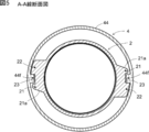
- 25A is a sectional view taken along the line AA in FIGS. 24A and 24B, and
- FIG. 25B is an enlarged view of a region R of FIG. 25A.
- FIGS. 26A to 26C are explanatory views showing a state in which the pair of split molds 202X and 202Y are gradually closed and the laminated parison P is clamped.
- FIG. 27A shows a first modification of the split molds 202X and 202Y shown in FIG. 25B
- FIG. 27B shows a second modification of the split molds 202X and 202Y.
- a laminated peeling container 1 as a container with a cap includes a substantially bottomed cylindrical container body 2 shown in FIGS. 1 to 3, a valve member 3 shown in FIG. And a cap 4 of the formula.
- the container body 2 is provided with a storage portion 5 for storing the content, a mouth portion 6 for discharging the content from the storage portion 5, and a shoulder portion 7.
- the diameter of the mouth portion 6 is smaller than the diameter of the housing portion 5, and the shoulder portion 7 connects the housing portion 5 and the mouth portion 6.
- the container body 2 has a multi-layered structure including an outer shell 12 and an inner bag 14 in the accommodation portion 5, the mouth portion 6 and the shoulder portion 7. 14 contracts away from the shell 12. Further, an air introduction hole 8 is provided only on the outer shell 12 of the side surface of the housing portion 5. A male screw portion 6a is provided on the outer peripheral surface of the mouth portion 6.
- the container body 2 of the present embodiment is provided with a riding portion 21 and a stopper portion 22 at the boundary between the mouth portion 6 and the shoulder portion 7.
- the stopper portion 22 is provided on the screw fastening direction side of the male screw portion 6 a (clockwise direction in FIGS. 1 and 2) with respect to the riding portion 21.
- the riding portion 21 is engaged with a protrusion 44f of the cap 4 which will be described later and restricts looseness of the cap 4. Further, the stopper portion 22 regulates the movement of the protrusion 44f to regulate the overrun of the cap 4.
- a concave portion 23 is formed between the riding portion 21 and the stopper portion 22, and when the cap 4 is screwed into the mouth portion 6, the protrusion 44f is positioned in the concave portion 23.
- a pair of the riding portion 21 and the stopper portion 22 are provided at positions facing each other in the circumferential direction, as shown in FIG.
- the valve member 3 is inserted into the air introduction hole 8 as shown in FIG.
- the valve member 3 is for adjusting the inflow/outflow of air between the space G between the outer shell 12 and the inner bag 14 and the outside.
- the gap between the edge of the air introduction hole 8 and the valve member 3 is opened and closed by the movement of the valve member 3, so that the valve member 3 opens and closes the air introduction hole 8 (Fig. 3)) or a valve that can be opened/closed is provided in the valve member 3 itself, and the air introduction hole 8 can be opened/closed by opening/closing the through hole by the function of this valve.
- valve member 3 is not provided, and a filter is attached to the air introduction hole 8 to adjust the inflow and outflow of air, or the air introduction hole 8 is simply blocked by a finger or the like when the contents are discharged. It can also be configured to perform. In any of the above configurations, the valve member 3 closes the air introduction hole 8 when the outer shell 12 is compressed to make the inner bag 14 compressible, and releases the compressive force to the outer shell 12. Then, the outside air is introduced into the space G.
- the accommodation part 5 is covered with a shrink film after the valve member 3 is attached.
- the valve member mounting recess 5a is formed in the housing portion 5 so that the valve member 3 does not interfere with the shrink film.
- an air circulation groove 5b extending from the valve member mounting recess 5a toward the shoulder 7 is provided so that the valve member mounting recess 5a is not sealed by the shrink film (see FIG. 1).
- valve member mounting recess 5a and the air circulation groove 5b are provided at substantially the same position in the circumferential direction as the pair of riding portions 21 and the stopper portion 22 or at positions facing each other in the circumferential direction. Due to such a positional relationship, in the vicinity of the riding portion 21 and the stopper portion 22, the inner bag 14 and the outer shell 12 are preliminarily separated from the outer shell 12 in the vicinity of the air introduction hole 8 when the valve member 3 is mounted. It becomes difficult to adhere to each other, and the inner bag 14 is easily peeled off when the contents are discharged.
- the valve member mounting recess 5a and the air circulation groove 5b around the air introduction hole 8 are formed. Both of them can be molded at a position deviated from the parting line by 90 degrees. Accordingly, it is possible to prevent an undercut from occurring in the molding of the valve member mounting recess 5a, the air circulation groove 5b, the riding portion 21 and the stopper portion 22.
- the cap 4 includes a cap body 41 and a cap cover 43 connected to the cap body 41 by a hinge 42.
- the cap body 41 includes three members: a main cap member 44, a check valve 45, and a discharge member 46.
- the main cap member 44 is composed of an outer tubular portion 44a, an inner tubular portion 44b, and an annular portion 44c that connects the upper ends thereof.
- a female screw portion 44d that is screwed with the male screw portion 6a of the mouth portion 6 of the container body 2 is formed.
- the end of the outer tubular portion 44a at a position lower than the female screw portion 44d (on the container body 2 side) is an enlarged diameter portion 44e having a larger diameter. ing.
- protrusions 44f protruding inward in the radial direction are formed at two locations facing each other in the circumferential direction (see FIGS. 4A, 4B and 5).
- the protrusion 44f is configured to engage with the riding portion 21 and the stopper portion 22 of the container body 2.
- the relationship between the protrusion 44f and the riding portion 21 and the stopper portion 22 will be described later.
- a valve seat 44g that supports the check valve 45 is formed inside the inner tubular portion 44b.
- the check valve 45 includes a valve body 45a and an elastic piece 45b.
- the check valve 45 is fixed in the inner cylindrical portion 44b of the main cap member 44 by the discharge member 46 engaging with the annular portion 44c of the cap body 41. Then, the check valve 45 is configured such that the valve body 45 a of the check valve 45 is pushed up from the valve seat 44 g of the main cap member 44 when the pressure inside the housing portion 5 (inside the inner bag 14) rises. As a result, by squeezing the container 5 of the container body 2, the contents in the container 5 can be discharged from the discharge port 46a of the discharge member 46.
- the check valve 45 is closed by the urging force of the elastic piece 45b of the check valve 45 that supports the valve body 45a.
- the male screw portion 6a of the mouth portion 6 and the female screw portion 44d of the cap 4 are screwed together, as described above.
- the pair of opposed projections 44f of the cap 4 ride on the corresponding riding portion 21 of the mouth portion 6 and fit into the recess 23, as shown in FIG.
- the surface of the riding portion 21 on the side opposite to the fastening direction is the inclined portion 21a inclined toward the fastening direction side as it goes radially outward, it is possible to easily get over the protrusion 44f. Has become.
- the riding portion 21 functions as a loosening prevention (return prevention), whereby the loosening of the cap 4 can be prevented.
- the mouth portion 6 of the present embodiment has the stopper portion 22 on the screw fastening direction side of the riding portion 21. This makes it possible to prevent the cap 4 from overrunning (overtightening) beyond a predetermined fastening position where the projection 44f and the recess 23 are fitted together.
- the laminated peeling container 1 of the present embodiment can easily grasp the end point of fastening by the click feeling due to the ride of the protrusion 44f, and further, the protrusion 44f and the stopper portion 22 can be separated from each other. The engagement enables the cap 4 to be positioned at an appropriate tightening position.
- the container body 2 since the container body 2 is divided into the outer shell 12 and the inner bag 14, each layer becomes thin and the strength of the stopper portion 22 and the like is limited. Further, in the case of the laminated peeling container 1, it is difficult to locally thicken the inner bag 14 to be peeled by the parison control, because it is necessary to form the inner bag 14 thinly. Therefore, depending on the tightening operation of the cap 4, the stopper portion 22 may be crushed or overrun beyond the stopper portion 22 due to insufficient strength of the stopper portion 22.
- the radial projection width T2 of the stopper portion 22 is set to be larger than the radial projection width T1 of the riding portion 21.
- the circumferential width W2 of the stopper portion 22 is set to be larger than the circumferential width W1 of the riding portion 21.
- the height H2 of the stopper portion 22 is also set to be larger than the height H1 of the riding portion 21.
- the riding portion 21 and the stopper portion 22 are provided at the boundary between the mouth portion 6 and the shoulder portion 7 so as to extend over both the mouth portion 6 and the shoulder portion 7. Even with such a configuration, the container body 2 of the present embodiment has the strength of the riding portion 21 and the stopper portion 22 as compared with the case where the riding portion 21 and the stopper portion 22 project from only the mouth portion 6 or only the shoulder portion 7. I am raising.
- the height H2 of the stopper portion 22 is set to be high, there is a risk that it will interfere with the other protrusion 44f approximately half the circumference before the end point of the fastening of the cap 4.
- the height H2 of the stopper portion 22 is set to a substantially maximum height that does not interfere with the other projection 44f, and the upper surface of the stopper portion 22 is tapered face 22f whose height decreases in the fastening direction. (See FIG. 6B). This makes it possible to prevent the attachment operation of the cap 4 from being hindered while maintaining the strength of the stopper portion 22.
- the stopper portion 22 also has a tapered surface 22g on the fastening direction side, the height of which decreases toward the fastening direction. Since the height H1 of the riding portion 21 is smaller than the height H2 of the stopper portion 22, it is not difficult for the protrusion 44f of the cap 4 to ride up.
- both the height H2 of the stopper portion 22 and the radial projection width T2 are larger than the height H1 of the riding portion 21 and the radial projection width T1.
- the height and the protrusion width of the riding portion 21 and the stopper portion 22 are not changed, and the width W2 of the stopper portion 22 in the circumferential direction is set to be larger than the width W1 of the riding portion 21 in the circumferential direction.
- the strength of the stopper portion 22 can be improved by making at least one of the height, the protrusion width, and the circumferential width of the stopper portion 22 larger than that of the riding portion 21.
- the projection 44f of the cap 4 is configured to project radially inward from the expanded diameter portion 44e.
- the protrusion 44f may be configured to extend downward from the end portion of the outer tubular portion 44a of the cap 4.
- a pair of the riding portion 21 and the stopper portion 22 of the container body 2 are provided at positions facing each other in the circumferential direction, but it is also possible to provide only one riding portion 21 and one stopper portion 22 each. It is possible.
- the container with a cap was the example which is the lamination peeling container 1, the container with a cap does not need to be the lamination peeling container 1. Even in the case of a normal container that does not peel off, the container body 2 is provided with the stopper portion 22 on the screw fastening direction side with respect to the riding portion 21 so that overrun of the cap 4 can be prevented.
- the double container 101 is a so-called laminated peeling container having an outer shell 112 and an inner bag 114, and the inner bag 114 shrinks as the contents decrease.
- the inner bag 114 separates from the outer shell 112 as the contents decrease, the inner bag 114 separates from the outer shell 112 and contracts. In such a container, it is difficult for outside air to enter the inner bag 114, so that deterioration of the contents is suppressed.
- the outer shell 112 is made of, for example, low-density polyethylene, linear low-density polyethylene, high-density polyethylene, polypropylene, ethylene-propylene copolymer and a mixture thereof.
- the outer shell 112 may have a multi-layer structure.
- the inner bag 114 is preferably composed of a plurality of layers.
- an EVOH layer made of an ethylene-vinyl alcohol copolymer (EVOH) resin is used for the layer in contact with the outer shell 112, and a low-density polyethylene, a linear low-density polyethylene, or a high-density polyethylene is used for the layer in contact with the contents.
- EVOH ethylene-vinyl alcohol copolymer
- An inner surface layer made of polyolefin such as density polyethylene, polypropylene, ethylene-propylene copolymer and a mixture thereof can be used. Then, it is preferable to use an adhesive layer between the EVOH layer and the inner surface layer.
- the double container 101 has a cylindrical shape with a bottom, and includes a storage section 107 for storing the content, and a mouth section 109 for discharging the content from the storage section 107.
- the housing portion 107 includes a body portion 107a and a bottom portion 107b.
- the mouth portion 109 is provided with an engaging portion (male screw portion) 109d so that a cap or a pump can be attached.
- the double container 101 When the double container 101 is formed by direct blow molding, the double container 101 has a cutout 107d formed by crushing a parison with a pair of split molds.
- the cut-out portion 107d is provided on the bottom portion 107b of the double container 101, and the opposite surfaces of the parison are welded to each other at the cut-out portion 107d, whereby the bottom of the double container 101 is closed.
- the biting portion 107d closes the bottom of each of the outer shell 112 and the inner bag 114.
- the outside air introducing portion 115 can be formed by opening the biting portion 107d.
- the outside air can be introduced between the outer shell 112 and the inner bag 114 through the outside air introduction unit 115.
- the outside air introducing portion 115 is formed in the cut-out portion 107d, the bottom portion of the inner bag 114 is hardly fixed to the bottom portion 107b of the double container 101. Therefore, the bottom portion 114a of the inner bag 114 easily separates from the bottom portion 107b of the double container 101 and floats up.
- the outside air introducing portion 115 may be formed by punching the outer shell 112.
- the outside air introducing section 115 may be provided in the housing section 107 or the mouth section 109.
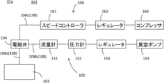
- the leak inspection device 102 includes a head 103, a solenoid valve 104, a pressure reducing system 105, a pressurizing system 106, and a pipe 108.
- the pipe 108 includes a pipe 108 a that connects the head 103 and the solenoid valve 104, a pipe 108 b that connects the decompression system 105 and the solenoid valve 104, and a pipe 108 c that connects the pressurization system 106 and the solenoid valve 104.
- the solenoid valve 104 By controlling the solenoid valve 104, it is possible to switch which of the pressure reducing system 105 and the pressurizing system 106 is connected to the head 103.
- the depressurization system 105 allows air to be sucked in through the head 103, and the pressurization system 106 allows air to be blown in through the head 103.
- the decompression system 105 includes a flow meter 151, a pressure gauge 152, a regulator 153, and a vacuum pump 154 in order from the solenoid valve 104 side.
- the vacuum pump 154 discharges the air in the pipe 108b to reduce the pressure in the pipe 108b.
- the regulator 153 controls the flow rate of the air flowing through the pipe 108b or the pressure of the air inside the pipe 108b.
- the pressure gauge 152 measures the pressure of air in the pipe 108b.
- the flowmeter 151 measures the flow rate of air flowing through the pipe 108b.
- the components included in the decompression system 105 may be changed in order or omitted as appropriate.
- the pressurization system 106 includes a speed controller 161, a regulator 162, and a compressor 163 in order from the solenoid valve 104 side.
- the compressor 163 supplies compressed air into the pipe 108c.
- the regulator 162 controls the pressure of air in the pipe 108c.
- the speed controller 161 controls the flow rate of air flowing in the pipe 108c. Note that the pressurization system 106 can be omitted if unnecessary, and in that case, the solenoid valve 104 can also be omitted.
- the head 103 includes a head base 131 and a packing 132.
- the head base 131 and the packing 132 are provided with through holes 131a and 132a, respectively, which communicate with the inside of the pipe 108a.
- the packing 132 is arranged in the accommodation recess 131 b of the head base 131.
- the packing 132 is made of a material such as an elastomer that can enhance airtightness.
- a leak inspection method for the double container 101 of this embodiment will be described. This method includes a step of determining whether or not there is a pinhole in the inner bag 114 based on the data obtained when the inside of the inner bag 114 is depressurized.
- This step can be performed by connecting the head 103 to the decompression system 105 and operating the vacuum pump 154 with the head 103 pressed against the end surface of the mouth 109.
- the air inside the inner bag 114 is sucked out to reduce the pressure inside the inner bag 114, and the inner bag 114 contracts as shown in FIG.
- the flow rate of air measured by the flow meter 151 rapidly increases, but the flow rate gradually decreases as the inner bag 114 contracts.
- the flow rate of the air becomes a very small value (nearly 0) when the inner bag 114 is deflated.
- the inner bag 114 is determined based on the flow rate of the air sucked from the inner bag 114 (more specifically, by checking whether or not this flow rate exceeds the threshold Th). It can be determined whether there is a pinhole in the.
- the degree of airtightness inside the inner bag 114 is low, and thus the degree of pressure reduction inside the inner bag 114 is less likely to increase. Therefore, with the set pressure of the vacuum pump 154 set to the reference value, it is determined whether or not there is a pinhole in the inner bag 114 based on the pressure detected by the pressure gauge 152 after a predetermined time has elapsed. You can Further, in addition to the flow rate and the pressure, it is also possible to determine the presence or absence of a pinhole based on data such as the contraction mode and contraction time of the inner bag 114. However, the determination based on the flow rate is preferable from the viewpoint of accuracy.
- the pinhole is inspected while depressurizing the inside of the inner bag 114, so it is difficult to miss the pinhole.
- the leak inspection method according to the present embodiment may be performed after performing a preliminary peeling step of peeling the inner bag 114 from the outer shell 112 in advance. It may be peeled from 112. In that case, preliminary peeling and leak inspection can be performed simultaneously, which is efficient.
- the inspection method according to the present embodiment has a significant technical significance in leak inspection in a colored double container.
- the solenoid valve 104 is operated to connect the head 103 to the pressurizing system 106, and the compressor 163 is operated in that state, whereby air is sent into the inner bag 114 and the inner bag 114 is closed. Inflate. This facilitates the step of filling the inner bag 114 with the contents.
- Second Embodiment of Second Aspect This embodiment is similar to the first embodiment, and the main difference is the configuration of the head 103. The difference will be mainly described below.
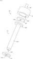
- the head 103 further includes an insertion member 133 and a packing 134.
- the insertion member 133 includes a rod portion 133a and a flange portion 133b protruding in the radial direction at the base end of the rod portion 133a.
- the packing 134 is provided with a through hole 134a, and the rod portion 133a is inserted into the through hole 134a.
- the material of the packing 134 is the same as that of the packing 132.
- the rod-shaped portion 133a is a rod-shaped portion.
- the insertion member 133 is provided with a through hole 133c, and the rod portion 133a is provided with a suction port 133d communicating with the through hole 133c.
- the suction port 133d is provided at the tip 133a1 of the rod-shaped portion 133a. Since the tip 133a1 is less likely to be covered by the inner bag 114 when the inner bag 114 contracts, the suction port 133d is provided to the tip 133a1 so that the suction port 133d is less likely to be blocked by the inner bag 114.
- the rod-shaped portion 133a is a portion to be inserted into the inner bag 114, it is preferable that the side surface and the edge of the tip of the rod-shaped portion 133a are curved so that the rod-shaped portion 133a does not damage the inner bag 114.
- the head base 131 when the head base 131 is pressed toward the end surface of the mouth portion 109, the head base 131, the flange portion 133b, and the end surface of the mouth portion 109 cause the packings 132 and 134 to be removed.
- the inner bag 114 is in close contact with the inner bag 114 through the through holes 131a, 132a, 133c, and the inside of the inner bag 114 can be depressurized or pressurized by the depressurization system 105 or the pressurization system 106. ..
- the inner bag 114 is decompressed while the rod-shaped portion 133a is inserted into the inner bag 114 from the mouth 109, and the inner bag 114 is contracted as shown in FIG. Then, the presence or absence of a pinhole in the inner bag 114 is confirmed. According to such a method, the following effects are exhibited.
- the inner bag 114 has a pair of opposing portions 114b and 114c that face each other with the biting portion 107d interposed therebetween.
- the inner bag 114 may be unevenly peeled and contracted so that the peeling progresses only in the portion 114b and the peeling does not progress in the portion 114c. If the inner bag 114 contracts in this way, it is a problem because the leak inspection cannot be effectively performed at the portion 114c.
- FIG. 16 As shown in FIG.
- L/H is 0.40 or more. Preferably. This is because in this case, the above two effects are effectively exhibited.
- L/H is, for example, 0.40 to 0.99, and specifically, for example, 0.40, 0.50, 0.60, 0.70, 0.80, 0.90, 0.95, 0.99, and may be in a range between any two of the numerical values exemplified here.
- D2/D1 is preferably 0.30 or more. This is because in this case, the above two effects are effectively exhibited.
- D2/D1 is, for example, 0.30 to 0.99, and specifically, for example, 0.30, 0.40, 0.50, 0.60, 0.70, 0.80, 0.90, 0.95 and 0.99, and may be in the range between any two of the numerical values exemplified here.
- L/D2 is preferably 3 or more, for example, 3 to 50, and specifically, for example, 3, 4, 5, 6, 7, 8, 9, 10, 20, 30, 40. , 50, and may be within a range between any two of the numerical values exemplified here.
- the present embodiment has excellent effects as a leak inspection method, but from the viewpoint of having the above-described two effects, it also has excellent effects as a preliminary peeling method for the double container 101. Therefore, from this viewpoint, the leak inspection is not essential.
- the suction port 133d may be provided at a portion other than the tip of the rod-shaped portion 133a.
- the suction port 133d is provided on the peripheral surface of the rod-shaped portion 133a, it is preferable that the inner bag 114 is provided at a position where it is difficult for the inner bag 114 to close the suction port 133d (eg, near the root of the rod-shaped portion 133a).
- the number of suction ports 133d may be two or more.
- the through hole 133c may be provided in the flange portion 133b. In this case, the packings 132 and 134 are provided with through holes that communicate with the through holes 133c.
- the rod-shaped portion 133a may also be provided with a through-hole 133c so as to reduce the pressure inside the inner bag 114 through both the rod-shaped portion 133a and the flange portion 133b.
- the inside of the inner bag 114 may be decompressed only from the flange 133b without providing the 133c.
- a laminated peeling container 201 according to an embodiment of the third aspect of the present invention includes a substantially bottomed cylindrical container body 203 and a pump 204.
- the container body 203 has a bottomed tubular shape, and includes a housing portion 233 having a body portion 231 and a bottom portion 232, and a mouth portion 234 for discharging the contents from the housing portion 233. ..
- a male screw portion 234a is provided on the outer surface of the mouth portion 234.
- the container main body 203 of the present embodiment is provided with the inner bag 206 and the outer shell 207 in the accommodation portion 233 and the mouth portion 234, and the inner bag 206 is separated from the outer shell 207 as the content decreases.
- Inner bag 206 is configured to contract away from outer shell 207.
- the inner bag 206 includes an EVOH layer provided on the outer surface side of the container, an inner surface layer provided on the inner surface side of the EVOH layer, and an adhesive layer provided between the EVOH layer and the inner surface layer.
- the adhesive layer may be omitted.
- the outer shell 207 is composed of, for example, low-density polyethylene, linear low-density polyethylene, high-density polyethylene, polypropylene, ethylene-propylene copolymer and a mixture thereof.
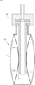
- the pump 204 is configured to discharge the contents from the container body 203 without introducing outside air into the container body 203.
- the pump 204 includes a main body 241, a piston 242, a nozzle 243, and a tube 244.
- the main body portion 241 includes a cylinder portion 241a and a cylinder portion 241b.
- a female screw portion (not shown) to be screwed into the male screw portion 234a of the mouth portion 234 of the container body 203 is provided on the inner surface of the cylindrical portion 241a.
- the lower portion of the cylinder portion 241b is inserted into the mouth portion 234.
- the outer diameter of the cylinder portion 241b is substantially equal to the inner diameter of the mouth portion 234.
- the cylinder portion 241b has a tubular shape, and the piston portion 242 is slidable inside the cylinder portion 241b.
- the internal space of the cylinder portion 241b is in communication with the nozzle 243 and the tube 244.
- a pump mechanism including an elastic member and a valve is built in the internal space of the cylinder portion 241b.
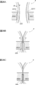
- the bottom portion 232 of the present embodiment is provided with a pinch-off portion 232p at its central portion, as shown in FIGS. 22A, 22B and 18B, 19 and the like.
- the pinch-off portion 232p has a strip-like structure formed by sandwiching the lower end of a laminated parison P described later between the cut-off portions 221X and 221Y (see FIG. 24A) of the split molds 202X and 202Y and crushing it.
- the bottom portion 232 has a double structure of the inner bag 206 and the outer shell 207 as described above, and is configured by fitting the inner bag bottom portion 260 shown in FIG. 23A and the outer shell bottom portion 270 shown in FIG. 23B. It
- the inner bag bottom portion 260 has an inner bag protruding portion 261 that protrudes outward at the pinch-off portion 232p.
- the outer shell bottom portion 270 has a holding portion 271 that holds the inner bag protruding portion 261 in the pinch-off portion 232p.
- An outside air introduction hole 208 is provided between the inner bag protruding portion 261 and the sandwiching portion 271 (see FIGS. 22A, 23B and 18B).
- the inner bag projecting portion 261 and the sandwiching portion 271 do not project from the bottom portion 232, but may be configured to project from the bottom portion 232.
- the inner bag protruding portion 261 and the sandwiching portion 271 are attached to each other, and the outside air introduction hole 208 is not provided.
- the inner bag protruding portion 261 and the sandwiching portion 271 are easily separated, the inner bag protruding portion 261 and the sandwiching portion 261 are separated by applying an impact or a twisting force so that the inner bag protruding portion 261 and the sandwiching portion 271 are separated.
- the outside air introduction hole 208 can be formed by separating 271. Since the container body 203 has the outside air introduction hole 208, it is possible to introduce the outside air between the outer shell 207 and the inner bag 206 as the content decreases and to shrink only the inner bag 206. Is becoming
- the container body 203 of the present embodiment serves as an engaging portion that engages the inner bag 206 and the outer shell 207 with the longitudinal end portion of the pinch-off portion 232p.
- a meat reservoir 209 is formed.
- the inner bag 206 inner bag bottom portion 260
- the outer shell 207 outer shell bottom portion 270
- the outer shell 207 includes a pair of concave portions 272 that engage with the convex portions 262, as shown in FIGS. 22B and 23B.
- the convex portion 262 of the inner bag 206 and the concave portion 272 of the outer shell 207 are engaged with each other in the meat reservoir 209 in this manner, so that the inner bag 206 is reduced as the content decreases. Even when contracted, the inner bag 206 is not easily detached from the bottom portion 232.
- the convex portion 262 and the concave portion 272 of the present embodiment are integrally formed by blow molding described later, and the convex portion 262 and the concave portion 272 have a shape in which they are closely fitted to each other.
- the protrusion 262 is formed such that the protrusion amount d1 in the longitudinal direction is 0.15 times or more the length d2 in the longitudinal direction from the center X of the bottom portion 232 to the tip of the protrusion 262. It
- the ratio of d1/d2 is preferably 0.18 or more, more preferably 0.20 or more.
- the ratio of d1/d2 is, for example, 0.15 to 0.30, and more preferably 0.20 to 0.25.
- the protrusion amount d1 in the longitudinal direction of the convex portion 262 is defined as the protrusion amount from the most constricted position of the inner bag bottom portion 260 in the cross section of the inner bag bottom portion 260 at the pinch-off portion 232p, as shown in FIG. 22B. To be done.
- the length of the protrusion amount d1 is specifically formed to be 1.5 mm or more.
- the protrusion amount d1 is preferably 2.0 mm or more. Further, the protrusion amount d1 is preferably 2.0 mm to 6.0 mm, more preferably 2.5 mm to 5.5 mm, and further preferably 3.5 mm to 4.5 mm.
- the specific value of the protrusion amount d1 is, for example, 2.0, 2.1, 2.2, 2.3, 2.4, 2.5, 2.6, 2.7, 2.8, 2. .9, 3.0, 3.1, 3.2, 3.3, 3.4, 3.5, 3.6, 3.7, 3.8, 3.9, 4.0, 4.1.
- the tip of the convex portion 262 of the present embodiment projects to a position substantially the same as the edge of the bottom surface of the inner bag 206 in the radial direction.
- the tip of the convex portion 262 may remain at a position inside the edge of the bottom surface of the inner bag 206 as long as the protrusion amount dl of the convex portion 262 can be sufficiently secured.
- the container body 203 is formed by blow molding a cylindrical laminated parison P extruded from the extruder 205, as shown in FIGS. 24A and 24B.
- the laminated parison P is extruded from a die 205a (die head) in a molten state, and this is clamped by a pair of split molds 202X and 202Y of the blow molding mold 202.
- the split molds 202X and 202Y have a cavity shape such that various shapes of the container body 203 such as the body portion 231, the bottom portion 232, and the mouth portion 234 are formed into a blow-molded product.
- the die diameter of the die 205a for extruding the laminated parison is the diameter of the portion forming the bottom of the inner diameter of the split mold 202X, 202Y.
- the inner diameter that is, 2/ ⁇ times or less of the diameter d4 of the bottom portion 232 (bottom surface).
- the fold diameter that is the width of the crushed laminated parison P (the width of the pinch-off portion 232p after molding and Is approximately smaller than the inner diameter d4 of the portion forming the bottom portion 232 of the container body 203.
- the ratio of d3/d4 is, for example, 0.1 to 0.63, and more preferably 0.19 to 0.42.
- the ratio of d3/d4 is specifically, for example, 0.19, 0.20, 0.21, 0.22, 0.23, 0.24, 0.25, 0.26, 0.27, 0. .28, 0.29, 0.30, 0.31, 0.32, 0.33, 0.34, 0.35, 0.36, 0.37, 0.38, 0.39, 0.40 , 0.41, 0.42, and may be in the range between any two of the numerical values exemplified here.
- the diameter d3 of the laminated parison P is, as shown in FIG. 24B, slightly smaller than the inner diameter d5 of the portion forming the mouth 234 of the container main body 203 in the inner diameter of the blow molding die 202.
- the ratio of d3/d5 is, for example, 0.6 to 0.9, and more preferably 0.7 to 0.8.
- the ratio of d3/d5 is specifically, for example, 0.70, 0.71, 0.72, 0.73, 0.74, 0.75, 0.76, 0.77, 0.78. , 0.79, 0.80, and may be in a range between any two of the numerical values exemplified here.
- the diameter d3 of the laminated parison P is too large with respect to the inner diameter d5 of the portion forming the mouth portion 234, burr biting or the like may occur during mold clamping, and if the diameter d3 of the laminated parison P is too thin, blown.
- the ratio becomes too large and molding becomes difficult.
- the mouth portion 234 can be suitably formed.
- the split molds 202X and 202Y of the blow molding mold 202 are provided with cut-off portions 221X and 221Y, respectively.
- the blow molding die 202 includes a compression portion 222 below the bite cutting portions 221X and 221Y.
- the compression part 222 is formed by the split molds 202X and 202Y and compresses the laminated parison P during mold clamping.
- the compression part 222 includes a first compression region 222a and a first compression region 222a, which are formed at positions near both ends in the longitudinal direction of the bite cutting parts 221X and 221Y. And a second compression region 222b arranged at a position between them.
- the width d6 of the first compression region 222a when the mold is clamped is narrower than the width d7 of the second compression region 222a when the mold is clamped.
- the width d6 of the first compression region 222a at the time of mold clamping is preferably set to be equal to or less than the thickness d8 (see FIG. 26A) of the laminated parison P.
- the width d6 of the first compression region 222a when the mold is clamped is preferably 1 mm or less, and more preferably 0.2 mm or less. Further, the width d6 is preferably such that the dies do not come into complete contact with each other, and is preferably 0.01 mm or more.
- the value of the width d6 is, for example, 0.01 mm to 1.00 mm, preferably 0.05 mm to 0.20 mm. Specifically, for example, 0.05, 0.06, 0.07, 0.08, 0.09, 0.10, 0.11, 0.12, 0.13, 0.14, 0.15. It is 0.16, 0.17, 0.18, 0.19, 0.20 mm, and may be in a range between any two of the numerical values exemplified here.
- the width d7 of the second compression region 222b when the mold is clamped is equal to or less than twice the thickness d8 of the laminated parison P.
- the width d7 is preferably 10 mm or less, and more preferably 8 mm or less.
- the value of the width d7 is, for example, 1.0 mm to 6.0 mm, more preferably 2.0 mm to 5.0 mm, and further preferably 3.0 mm to 4.0 mm.
- FIGS. 26A to 26C show a state in which the laminated parison P is hung on the blow molding die 202 having the above-described configuration, and the pair of split dies 202X and 202Y are gradually closed. It is a thing.
- the split molds 202X and 202Y are closed from the state before clamping in FIG. 26A, the cylindrical laminated parison P is pressed inward by the cut-off portions 221X and 221Y of the split molds 202X and 202Y, and FIG. As shown, first, the inner surfaces (layers forming the inner bag 206) of the laminated parison P contact each other.
- the laminated parison P is compressed by the bite cutting portions 221X and 221Y and the compression portion 222. Then, as shown in FIG. 26C, when the mold is completely closed, the laminated parison P is separated into two by the cut-off portions 221X and 221Y, and the pinch-off portion 232p is formed on the container side.
- the laminated parison P is gradually compressed.
- the laminated parison P is positioned below (above the container) above (the inside of the container) the bite parts 221X and 221Y. More compressed. Therefore, the crushed laminated parison P is likely to flow in the container inner direction (see the arrow in FIG. 26B) having a large space.
- the compression part 222 of the present embodiment includes the first compression region 222a and the second compression region 222b, and the width d6 of the first compression region 222a near both ends in the longitudinal direction of the bite parts 221X and 221Y is the first. It is configured to be narrower than the width d7 of the two compression regions 222b.
- the laminated parison P crushed by the compression portion 222 is prevented from spreading in the lateral direction (longitudinal direction of the cut-off portions 221X and 221Y, the left-right direction in FIG. 24B). Therefore, the laminated parison P moves in the vertical direction and is pushed back into the cavity, so that the laminated parison P is more likely to flow in the container inward direction.
- the protrusion amount d1 of the convex portion 262 of the inner bag 206 can be increased, the fitting with the concave portion 272 of the outer shell 207 can be strengthened, and the detachment of the inner bag 206 from the bottom portion 232 can be suppressed. It is possible.
- the laminated parison P was compressed by the compression part 222.
- the width of the compression portion 222 is constant, the protrusion amount d1 of the convex portion 262 of the inner bag 206 cannot be sufficiently obtained.
- the compression portion 222 is composed of the above-described first compression region 222a and second compression region 222b, the protrusion amount d1 can be increased.
- the ratio d1/d2 of the protrusion amount d1 in the longitudinal direction of the convex portion 262 and the length d2 in the longitudinal direction from the center X of the bottom portion 232 to the tip of the convex portion 262 can also be increased as described above. Has become. (See Figure 22B).
- the convex portion 262 of the inner bag 206 is engaged with the concave portion 272 of the outer shell 207 in the meat reservoir 209, so that the inner bag 206 moves from the bottom portion 232.
- it is difficult to remove the inner bag 206 it does not mean that the inner bag 206 is not removed at all. That is, since the convex portion 262 of the inner bag 206 is only engaged with the concave portion 272 of the outer shell 207, the remaining amount of the contents in the laminated peeling container 201 is small, and the shrinkage amount of the inner bag 206 is small.
- the convex portion 262 and the concave portion 272 are disengaged due to the deformation of the inner bag 206.
- the inner bag 206 can be more freely deformed, and it is possible to collect the contents at the end of the tube 244 by suction of the pump 204 and discharge the contents to the end.
- the invention of the third aspect can also be implemented in the following modes.
- the pair of split molds 202X and 202Y of the blow molding mold 202 are configured to completely abut at the outer position of the first compression region 222a.
- the blow molding die 202 of the present invention is not limited to such a configuration. That is, as shown in FIG. 27A, the first compression region 222a may be continuous to the end of the mold. Further, as shown in FIG.
- the gap between the pair of split molds 202X and 202Y is the first compression region.
- the width d6 of the 222a may be larger than the width d6.
- the laminated peeling container 201 is configured to discharge the contents by the pump 204, but it is also possible to squeeze the container body 203 to discharge the contents.
- the outside air introduction hole 208 is provided in the bottom portion 232, but it may be provided in the body portion 231. Further, in this case, it is also preferable to provide a valve member in the outside air introduction hole 208.
- D2 length from the center of the bottom portion to the tip of the convex portion
- d3 diameter of the laminated parison P
- d4 diameter of the bottom portion
- d5 inner diameter of the portion forming the mouth portion
- d6 width of the first compression region
- d7 width of second compression region
- d8 thickness of laminated parison P
Landscapes
- Engineering & Computer Science (AREA)
- Mechanical Engineering (AREA)
- Ceramic Engineering (AREA)
- Containers Having Bodies Formed In One Piece (AREA)
- Containers And Packaging Bodies Having A Special Means To Remove Contents (AREA)
- Packages (AREA)
- Closures For Containers (AREA)
Abstract
キャップのオーバーランを防止することの可能なキャップ付き容器を提供する。 本発明によれば、容器本体及びキャップを有するキャップ付き容器であって、前記キャップは雌ねじ部を備え、前記容器本体はその口部に前記雌ねじ部と螺合する雄ねじ部を備えており、前記キャップは、前記雌ねじ部よりも前記容器本体側の位置に突起を備え、前記容器本体は、前記突起と係合して前記キャップの緩みを規制する乗り上げ部と、当該乗り上げ部よりもねじの締結方向側に位置し前記キャップのオーバーランを規制するストッパ部とを備えている、キャップ付き容器が提供される。
Description
本発明は、キャップ付き容器、二重容器のリーク検査方法、積層剥離容器及びその製造方法に関する。
(第1観点)
従来、雄ねじ部が形成された口部を有する容器本体と、雌ねじ部が形成されたキャップをとを備えるキャップ付き容器が知られている。例えば、特許文献1には、キャップを螺合により締め付けた際の緩み止めとして、雄ねじ部のねじ山の終端部に乗り上げ部(突起)を設けたものが開示されている。この構成では、キャップの下面に設けられた突起が乗り上げ部を超えた際のクリック感により、締め付け時の終点を把握することが可能となっている。
従来、雄ねじ部が形成された口部を有する容器本体と、雌ねじ部が形成されたキャップをとを備えるキャップ付き容器が知られている。例えば、特許文献1には、キャップを螺合により締め付けた際の緩み止めとして、雄ねじ部のねじ山の終端部に乗り上げ部(突起)を設けたものが開示されている。この構成では、キャップの下面に設けられた突起が乗り上げ部を超えた際のクリック感により、締め付け時の終点を把握することが可能となっている。
(第2観点)
特許文献2では、内袋内に空気を供給し、所定時間経過後に内袋内の圧力が所定値に到達するかどうかに基いて、内袋の穴あきの有無を検査している。
特許文献2では、内袋内に空気を供給し、所定時間経過後に内袋内の圧力が所定値に到達するかどうかに基いて、内袋の穴あきの有無を検査している。
(第3観点)
従来、外殻と内袋とを有し且つ内容物の減少に伴って内袋が収縮する積層剥離容器が知られている(例えば、特許文献3)。このような積層剥離容器は、一般に、円筒状の積層パリソンを用いたブロー成形によって製造される。
従来、外殻と内袋とを有し且つ内容物の減少に伴って内袋が収縮する積層剥離容器が知られている(例えば、特許文献3)。このような積層剥離容器は、一般に、円筒状の積層パリソンを用いたブロー成形によって製造される。
(第1観点)
しかしながら、上記特許文献1の構成においては、キャップの突起が乗り上げ部を超えた後も、原理的にはさらにキャップを締め付けることが可能であり、未だ締め付け過ぎ(オーバーラン)が生じるおそれが残っていた。
しかしながら、上記特許文献1の構成においては、キャップの突起が乗り上げ部を超えた後も、原理的にはさらにキャップを締め付けることが可能であり、未だ締め付け過ぎ(オーバーラン)が生じるおそれが残っていた。
本発明はこのような事情に鑑みてなされたものであり、キャップのオーバーランを防止することの可能なキャップ付き容器を提供するものである。
(第2観点)
特許文献2の方法では、内袋内に空気を供給したときに内袋が意図せずして膨らんでしまうと、内袋に穴あきが存在しない場合にも関わらず、内袋に穴あきが存在していると判定される虞があり、別の手段によるリーク検査方法が望まれている。
特許文献2の方法では、内袋内に空気を供給したときに内袋が意図せずして膨らんでしまうと、内袋に穴あきが存在しない場合にも関わらず、内袋に穴あきが存在していると判定される虞があり、別の手段によるリーク検査方法が望まれている。
本発明はこのような事情に鑑みてなされたものであり、二重容器の内袋にピンホールが存在しているかどうかを検出することが可能なリーク検査方法を提供するものである。
(第3観点)
特許文献3に示されるような積層剥離容器の底部には、積層パリソンの一端を溶着した際のピンチオフ部(シール部)が設けられるが、このピンチオフ部において、底部から内袋が脱離することがある。内袋に内容物が残存している状態で内袋が底部から内袋が脱離すると、内袋の収縮の仕方が規制できず、流路が塞がってしまったり、ピンホールの発生につながるおそれがある。特許文献3の積層剥離容器では、ピンチオフ部における溶着層が複数の食い込み部により相互に噛合うように癒着させているが、このような構成を実現するためには、金型構造が複雑になり、生産コストの増大に繋がる。また、このような構成では、ピンチオフ部に、外殻と内袋の間に外気を導入する外気導入部を設けることができないという問題もあった。
特許文献3に示されるような積層剥離容器の底部には、積層パリソンの一端を溶着した際のピンチオフ部(シール部)が設けられるが、このピンチオフ部において、底部から内袋が脱離することがある。内袋に内容物が残存している状態で内袋が底部から内袋が脱離すると、内袋の収縮の仕方が規制できず、流路が塞がってしまったり、ピンホールの発生につながるおそれがある。特許文献3の積層剥離容器では、ピンチオフ部における溶着層が複数の食い込み部により相互に噛合うように癒着させているが、このような構成を実現するためには、金型構造が複雑になり、生産コストの増大に繋がる。また、このような構成では、ピンチオフ部に、外殻と内袋の間に外気を導入する外気導入部を設けることができないという問題もあった。
本発明はこのような事情に鑑みてなされたものであり、底部からの内袋の脱離が制限された積層剥離容器を提供するものである。
(第1観点)
本発明によれば、容器本体及びキャップを有するキャップ付き容器であって、前記キャップは雌ねじ部を備え、前記容器本体はその口部に前記雌ねじ部と螺合する雄ねじ部を備えており、前記キャップは、前記雌ねじ部よりも前記容器本体側の位置に突起を備え、前記容器本体は、前記突起と係合して前記キャップの緩みを規制する乗り上げ部と、当該乗り上げ部よりもねじの締結方向側に位置し前記キャップのオーバーランを規制するストッパ部とを備えている、キャップ付き容器が提供される。
本発明によれば、容器本体及びキャップを有するキャップ付き容器であって、前記キャップは雌ねじ部を備え、前記容器本体はその口部に前記雌ねじ部と螺合する雄ねじ部を備えており、前記キャップは、前記雌ねじ部よりも前記容器本体側の位置に突起を備え、前記容器本体は、前記突起と係合して前記キャップの緩みを規制する乗り上げ部と、当該乗り上げ部よりもねじの締結方向側に位置し前記キャップのオーバーランを規制するストッパ部とを備えている、キャップ付き容器が提供される。
本発明によれば、容器本体が乗り上げ部よりもねじの締結方向側にストッパ部とを備えていることから、キャップのオーバーランを防止することが可能となっている。
好ましくは、前記ストッパ部の高さと、当該ストッパ部の径方向の突出幅の少なくとも一方を、前記乗り上げ部のものよりも大きくした。
好ましくは、前記突起は周方向における対向する2箇所に設けられ、前記乗り上げ部及び前記ストッパ部も、周方向における対向する2箇所にそれぞれ設けられている。
好ましくは、一方の突起のオーバーランを規制するストッパ部の高さは、他方の突起と干渉しない略最大の高さとされる。
好ましくは、前記ストッパ部は、周方向における前記ねじの締結方向側に、前記他方の突起との干渉を防止するテーパ面を有する。
好ましくは、前記容器本体は、外殻と内袋とを有し且つ内容物の減少に伴って前記内袋が収縮するよう構成される。
好ましくは、前記外殻には空気導入孔が形成されており、前記乗り上げ部及び前記ストッパ部は、前記空気導入孔と周方向における略同一の位置又は周方向において対向する位置に設けられる。
(第2観点)
本発明によれば、二重容器のリーク検査方法であって、前記二重容器は、外殻と内袋とを有し且つ内容物の減少に伴って前記内袋が収縮するように構成され、前記方法は、前記内袋の内部の減圧時に得られるデータに基づいて前記内袋にピンホールが存在するか否かの判定を行う工程を備える、方法が提供される。
本発明によれば、二重容器のリーク検査方法であって、前記二重容器は、外殻と内袋とを有し且つ内容物の減少に伴って前記内袋が収縮するように構成され、前記方法は、前記内袋の内部の減圧時に得られるデータに基づいて前記内袋にピンホールが存在するか否かの判定を行う工程を備える、方法が提供される。
内袋の内部の減圧時に内袋の内部から吸い出されるエアーの流量や減圧の圧力等のデータは、内袋にピンホールが存在しているか否かによって差異が生じる。この差異に基づいて内袋にピンホールが存在するか否かを判定することができる。
以下、本発明の種々の実施形態を例示する。以下に示す実施形態は互いに組み合わせ可能である。
好ましくは、前記記載の方法であって、前記判定は、前記減圧時に前記内袋から吸い出されるエアーの流量に基づいて行われる、方法である。
好ましくは、前記記載の方法であって、前記減圧は、前記二重容器の口部から前記内袋内に棒状部が挿入された状態で行われる、方法である。
好ましくは、二重容器の予備剥離方法であって、前記二重容器は、外殻と内袋とを有し且つ内容物の減少に伴って前記内袋が収縮するように構成され、前記方法は、前記二重容器の口部から前記内袋内に棒状部が挿入された状態で、前記内袋の内部を減圧することによって前記内袋を前記外殻から剥離する工程を備える、方法である。
好ましくは、前記記載の方法であって、前記二重容器の全高をHとし、前記棒状部のうち前記内袋内に挿入されている部位の長さをLとすると、L/Hは、0.40以上である、方法である。
好ましくは、前記記載の方法であって、前記口部の内周面の内接円径をD1とし、前記棒状部の外接円径をD2とすると、D2/D1は、0.30以上である、方法である。
好ましくは、前記記載の方法であって、前記減圧は、前記棒状部に設けられた吸込口を通じて行われる、方法である。
好ましくは、前記記載の方法であって、前記吸込口は、前記棒状部の先端に設けられる、方法である。
(第3観点)
本発明によれば、外殻と内袋とを有し且つ内容物の減少に伴って前記内袋が収縮する積層剥離容器であって、内容物を収容する収容部と、当該収容部の底部に形成されるピンチオフ部とを備え、前記ピンチオフ部の長手方向の端部に、前記外殻と前記内袋が係合する係合部を備え、前記内袋は、前記係合部において、前記長手方向の外側に突出する凸部を備え、前記外殻は、前記係合部において、前記凸部と係合する凹部を備えており、前記凸部の前記長手方向における突出量は、前記底部の中心から前記凸部の先端までの前記長手方向における長さの0.15倍以上である、積層剥離容器が提供される。
本発明によれば、外殻と内袋とを有し且つ内容物の減少に伴って前記内袋が収縮する積層剥離容器であって、内容物を収容する収容部と、当該収容部の底部に形成されるピンチオフ部とを備え、前記ピンチオフ部の長手方向の端部に、前記外殻と前記内袋が係合する係合部を備え、前記内袋は、前記係合部において、前記長手方向の外側に突出する凸部を備え、前記外殻は、前記係合部において、前記凸部と係合する凹部を備えており、前記凸部の前記長手方向における突出量は、前記底部の中心から前記凸部の先端までの前記長手方向における長さの0.15倍以上である、積層剥離容器が提供される。
本発明によれば、ピンチオフ部の長手方向の端部に係合部を設け、係合部において内袋の凸部と外殻の凹部とを係合させることで、内袋の脱離を制限することが可能となっている。
以下、本発明の種々の実施形態を例示する。以下に示す実施形態は互いに組み合わせ可能である。
好ましくは、前記凸部の先端は、前記内袋の底面の縁と径方向において略同一の位置まで突出するか又は、前記内袋の底面の縁よりも外側に突出している。
好ましくは、前記ピンチオフ部に、前記外殻と前記内袋の間の空間に外気を導入する外気導入孔を備える。
また、本発明によれば、外殻と内袋とを有し且つ内容物の減少に伴って前記内袋が収縮する積層剥離容器の製造方法であって、円筒状の積層パリソンを用いたブロー成形工程を備え、前記金型は、前記積層剥離容器のピンチオフ部を成形する食い切り部の近傍に、型締め前に前記積層パリソンを圧縮して当該積層パリソンを容器内側方向に流動させるコンプレッション部を備え、前記コンプレッション部は、前記食い切り部の長手方向両端部近傍の位置に構成される第1コンプレッション領域と、当該第1コンプレッション領域の間の位置に構成される第2コンプレッション領域とを備え、前記第1コンプレッション領域の型締め時における幅は、第2コンプレッション領域の型締め時における幅よりも狭い、積層剥離容器の製造方法が提供される。
好ましくは、前記積層パリソンを押し出すダイス径は、前記金型の内径のうち底部を形成する部分の内径の2/π倍以下である。
好ましくは、前記第1コンプレッション領域の型締め時における幅は、前記積層パリソンの肉厚以下であり、前記第2コンプレッション領域の型締め時における幅は、前記積層パリソンの肉厚の2倍以下である。
好ましくは、前記第2コンプレッション領域は、型締め時における幅が5mm以下である。
以下、本発明の実施形態について説明する。以下に示す実施形態中で示した各種特徴事項は、互いに組み合わせ可能である。また、各特徴について独立して発明が成立する。
(第1観点の実施形態)
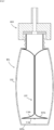
本発明の第1観点の一実施形態のキャップ付き容器としての積層剥離容器1は、図1~図3に示す略有底円筒状の容器本体2と、図3に示す弁部材3と、ねじ式のキャップ4とを備える。
本発明の第1観点の一実施形態のキャップ付き容器としての積層剥離容器1は、図1~図3に示す略有底円筒状の容器本体2と、図3に示す弁部材3と、ねじ式のキャップ4とを備える。
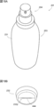
容器本体2は、図1に示すように、内容物を収容する収容部5と、収容部5から内容物を吐出する口部6と、肩部7とを備える。本実施形態において、口部6の径は収容部5の径よりも小さくなっており、肩部7によって、収容部5と口部6とが接続されている。
容器本体2は、図3に示すように、収容部5、口部6及び肩部7において、外殻12と内袋14の複数層構成となっており、内容物の減少に伴って内袋14が外殻12から離れて収縮する。また、収容部5の側面には、その外殻12のみに、空気導入孔8が設けられる。そして、口部6の外周面には、雄ねじ部6aが設けられる。
加えて、本実施形態の容器本体2は、図1及び図2に示すように、その口部6と肩部7との境界部分に、乗り上げ部21とストッパ部22とを備える。ストッパ部22は、乗り上げ部21よりも雄ねじ部6aのねじの締結方向側(図1及び図2では時計回りの方向)に設けられる。乗り上げ部21は、後述するキャップ4の突起44fと係合してキャップ4の緩みを規制するものである。また、ストッパ部22は、突起44fの移動を規制してキャップ4のオーバーランを規制するものである。乗り上げ部21とストッパ部22の間の位置には、凹部23が形成され、キャップ4を口部6に螺合した際には、突起44fが凹部23に位置づけられる。本実施形態において、乗り上げ部21及びストッパ部22は、図2に示すように、周方向の対向する位置に一対設けられる。
弁部材3は、図3に示すように、空気導入孔8に挿入される。弁部材3は、外殻12と内袋14の間の空間Gと外部との間の空気の出入りを調節するためのものである。弁部材3の構成としては、例えば、空気導入孔8の縁と弁部材3の間の隙間を弁部材3の移動によって開閉することによって、弁部材3が空気導入孔8を開閉する構成(図3参照)や、弁部材3自体に貫通孔と開閉可能な弁を設け、この弁の働きによって貫通孔を開閉することによって空気導入孔8を開閉する構成とすることができる。また、弁部材3を設けず、空気導入孔8にフィルタを貼り付けることで空気の出入りを調節する構成や、単に内容物を吐出する際に空気導入孔8を指などで閉塞させて調整を行う構成とすることもできる。弁部材3は、上記いずれの構成であっても、外殻12を圧縮した際には空気導入孔8を閉塞して内袋14を圧縮可能な状態とし、外殻12への圧縮力を解除すると空間G内に外気が導入されるよう構成される。
収容部5は、弁部材3を取り付けた後にシュリンクフィルムで覆われる。この際に、弁部材3がシュリンクフィルムに干渉しないように、収容部5には弁部材取付凹部5aが形成される。また、弁部材取付凹部5aがシュリンクフィルムで密閉されてしまわないよう、弁部材取付凹部5aから肩部7の方向に延びる空気流通溝5bが設けられる(図1参照)。
なお、本実施形態において、弁部材取付凹部5a及び空気流通溝5bは、一対の乗り上げ部21及びストッパ部22と周方向における略同一の位置又は周方向において対向する位置に設けられる。このような位置関係により、乗り上げ部21及びストッパ部22の近傍では、弁部材3の装着時に空気導入孔8近傍の内袋14を外殻12から予備剥離した後に内袋14と外殻12が密着しにくくなり、内容物の吐出時に内袋14が剥離しやすくなっている。
また、この位置関係により、本実施形態の容器本体2をブロー成形により成形する際に、空気導入孔8の周囲の弁部材取付凹部5a及び空気流通溝5bと、乗り上げ部21及びストッパ部22を、ともにパーティングラインと90度ずれた位置で成形することができる。これにより、弁部材取付凹部5a、空気流通溝5b、乗り上げ部21及びストッパ部22の成形においてアンダーカットが生じないようにすることが可能である。
キャップ4は、図3に示すように、キャップ本体41と、ヒンジ42により当該キャップ本体41と接続されたキャップカバー43とを備える。キャップ本体41は、主キャップ部材44と、逆止弁45と、吐出部材46の3つの部材から構成される。
主キャップ部材44は、外側筒部44aと、内側筒部44bと、これらの上端同士を接続する環状部44cとから構成される。外側筒部44aの内周面には、容器本体2の口部6の雄ねじ部6aと螺合する雌ねじ部44dが形成される。また、外側筒部44aの雌ねじ部44dよりも下方(容器本体2側)の位置の端部は、図3及び図4A、図4Bに示すように、径の大きくなった拡径部44eとなっている。そして、拡径部44eの内側には、周方向の対向する2箇所に、径方向内側に向かって突出する突起44fが形成される(図4A、図4B及び図5参照)。突起44fは、容器本体2の乗り上げ部21及びストッパ部22と係合するよう構成される。この突起44fと、乗り上げ部21及びストッパ部22との関係については、後述する。一方、内側筒部44bの内側には、逆止弁45を支持する弁座44gが形成される。
逆止弁45は、弁体45aと、弾性片45bとを備える。逆止弁45は、吐出部材46がキャップ本体41の環状部44cに係合することで、主キャップ部材44の内側筒部44b内に固定される。そして、逆止弁45は、収容部5内(内袋14内)の圧力が上昇すると、逆止弁45の弁体45aが主キャップ部材44の弁座44gから押し上げられるよう構成される。これにより、容器本体2の収容部5をスクイズすることで、収容部5内の内容物を吐出部材46の吐出口46aから吐出可能となっている。また、スクイズを止めると、弁体45aを支持する逆止弁45の弾性片45bの付勢力により、逆止弁45が閉じるようになっている。このような構成により、本実施形態の積層剥離容器1では、内袋14内への外気の流入が防止されるため、内容物の劣化が抑制されるようになっている。
以下、キャップ4の口部6への取り付け構造について、図5~図6Bを用いてより詳細に説明する。
キャップ4を容器本体2の口部6へ取り付ける際には、上述したように、口部6の雄ねじ部6aとキャップ4の雌ねじ部44dを螺合させる。ねじ山の端部までキャップ4を締結方向に回すと、図5に示すように、キャップ4の対向する一対の突起44fが対応する口部6の乗り上げ部21に乗り上げ、凹部23に嵌合する。ここで、乗り上げ部21は、その締結方向と反対側の面が、径方向外側に向かうにつれて締結方向側に傾斜した傾斜部21aとなっていることで、突起44fを容易に乗り越えさせることが可能となっている。また、一度突起44fが凹部23に嵌合した後は、乗り上げ部21が緩み止め(戻り止め)として機能することで、キャップ4の緩みを防止することが可能となっている。
さらに、本実施形態の口部6は、乗り上げ部21のねじの締結方向側にストッパ部22を有している。これにより、キャップ4が突起44fと凹部23の嵌合する所定の締結位置を超えてオーバーランしてしまう(締め付け過ぎてしまう)ことを抑制することが可能となっている。このような構成により、本実施形態の積層剥離容器1は、キャップ4の取り付け時において、突起44fの乗り上げによるクリック感により締結の終点を容易に把握でき、また、突起44fとストッパ部22との係合により、適切な締め付け位置にキャップ4を位置決めすることが可能となっている。
ただし、本実施形態のような積層剥離容器1では、容器本体2が外殻12と内袋14に分かれているため、各層が薄肉となり、ストッパ部22等の強度には限界がある。また、積層剥離容器1の場合、剥離させる内袋14を薄く成形する必要があるため、パリソンコントロールによる局所的な厚肉化は困難である。したがって、キャップ4の締め付け動作によっては、ストッパ部22の強度不足により、ストッパ部22が潰れたり、ストッパ部22を超えたオーバーランが生じてしまうおそれがあった。
そこで、本実施形態の容器本体2は、図6Aに示すように、ストッパ部22の径方向の突出幅T2を、乗り上げ部21の径方向の突出幅T1よりも大きく設定している。また、ストッパ部22の周方向の幅W2を、乗り上げ部21の周方向の幅W1よりも大きく設定している。さらに、図6Bに示すように、ストッパ部22の高さH2も、乗り上げ部21の高さH1よりも大きく設定している。このような構成により、容器本体2の肉厚を厚くすることなく、ストッパ部22の強度を高めることが可能となっている。
加えて、乗り上げ部21及びストッパ部22は、口部6と肩部7との境界部分に、口部6と肩部7の両方に跨るよう設けれられている。本実施形態の容器本体2は、このような構成によっても、乗り上げ部21及びストッパ部22を口部6のみあるいは肩部7のみから突出させる場合に対し、乗り上げ部21及びストッパ部22の強度を高めている。
なお、ストッパ部22の高さH2を高く設定すると、キャップ4の締結の終点の略半周前に、他方の突起44fと干渉するおそれがある。しかしながら、本実施形態では、ストッパ部22の高さH2を、当該他方の突起44fと干渉しない略最大の高さとし、ストッパ部22の上面を、締結方向に向かうにつれて高さの低くなるテーパ面22fとしている(図6B参照)。これにより、ストッパ部22の強度を保ちつつ、キャップ4の取り付け動作が妨げられることを防止することが可能となっている。さらに、本実施形態では、ストッパ部22の締結方向側も、締結方向に向かうにつれて高さの低くなるテーパ面22gとなっている。なお、乗り上げ部21の高さH1はストッパ部22の高さH2よりも小さくなっているため、キャップ4の突起44fの乗り上げが困難になることはない。
なお、第1観点の発明は、以下の態様でも実施可能である。
・上記実施形態においては、ストッパ部22の高さH2と、径方向の突出幅T2をともに、乗り上げ部21の高さH1及び径方向の突出幅T1よりも大きくしていた。しかしながら、ストッパ部22の高さと径方向の突出幅T2のうちの一方のみを、乗り上げ部21のものよりも大きくする構成とすることも可能である。このような構成であっても、ストッパ部22の強度を向上させることが可能である。さらに、乗り上げ部21及びストッパ部22の高さ及び突出幅は変えず、ストッパ部22の周方向の幅W2を、乗り上げ部21の周方向の幅W1よりも大きく設定することのみによっても、ストッパ部22の強度を向上させることが可能である。ストッパ部22の高さ、突出幅及び周方向の幅の少なくとも1つを乗り上げ部21よりも大きくすることで、ストッパ部22の強度を向上させることが可能である。
・上記実施形態において、キャップ4の突起44fは拡径部44eから径方向内側に向かって突出する構成であった。しかしながら、突起44fは、キャップ4の外側筒部44aの端部から下方向に延びる構成とすることも可能である。
・上記実施形態では、容器本体2の乗り上げ部21及びストッパ部22は周方向に対向する位置に一対設けられていたが、乗り上げ部21及びストッパ部22をそれぞれ1つのみ設ける構成とすることも可能である。また、乗り上げ部21及びストッパ部22を3つ以上設ける構成とすることも可能である。
・上記実施形態では、キャップ付き容器が積層剥離容器1である例を説明したが、キャップ付き容器は積層剥離容器1でなくてもよい。通常の剥離しない容器であっても、容器本体2が乗り上げ部21よりもねじの締結方向側にストッパ部22を備えることで、キャップ4のオーバーランを防止することが可能である。
(第2観点の実施形態)
1.第2観点の第1実施形態
本発明の第2観点の第1実施形態の二重容器のリーク検査方法について説明する。
1.第2観点の第1実施形態
本発明の第2観点の第1実施形態の二重容器のリーク検査方法について説明する。
<二重容器101>
まず、図7、図10及び図11を用いて、リーク検査の対象となる二重容器101について説明する。二重容器101は、外殻112と内袋114とを有し且つ内容物の減少に伴って内袋114が収縮する、いわゆる積層剥離容器である。内容物の減少に伴って内袋114が外殻112から離れることによって、内袋114が外殻112から離れて収縮する。このような容器では、内袋114内に外気が侵入しにくいので、内容物の劣化が抑制される。
まず、図7、図10及び図11を用いて、リーク検査の対象となる二重容器101について説明する。二重容器101は、外殻112と内袋114とを有し且つ内容物の減少に伴って内袋114が収縮する、いわゆる積層剥離容器である。内容物の減少に伴って内袋114が外殻112から離れることによって、内袋114が外殻112から離れて収縮する。このような容器では、内袋114内に外気が侵入しにくいので、内容物の劣化が抑制される。
外殻112は、例えば、低密度ポリエチレン、直鎖状低密度ポリエチレン、高密度ポリエチレン、ポリプロピレン、エチレン-プロピレン共重合体及びその混合物などで構成される。外殻112は、複数層構成であってもよい。内袋114は、複数の層から構成することが好ましい。例えば、外殻112と接触する層にエチレン-ビニルアルコール共重合体(EVOH)樹脂からなるEVOH層を用い、内容物に接触する層に、例えば、低密度ポリエチレン、直鎖状低密度ポリエチレン、高密度ポリエチレン、ポリプロピレン、エチレン-プロピレン共重合体及びその混合物などのポリオレフィンからなる内面層を用いることができる。そして、上記EVOH層と内面層との間には、接着層を用いることが好ましい。
二重容器101は、有底筒状であり、内容物を収容する収容部107と、収容部107から内容物を吐出する口部109を備える。収容部107は、胴部107aと、底部107bを備える。口部109には係合部(雄ねじ部)109dが設けられており、キャップやポンプを装着可能になっている。
ダイレクトブロー成形によって二重容器101を形成する場合、二重容器101には、一対の分割金型でパリソンを押し潰して形成した喰切部107dが存在している。喰切部107dは二重容器101の底部107bに設けられており、喰切部107dにおいてパリソンの対向する面同士が溶着されることよって二重容器101の底が閉じられている。喰切部107dは、外殻112と内袋114のそれぞれの底部を閉塞させているが、外殻112では喰切部107dの強度が特に弱いので、外殻112に衝撃を加えることによって外殻112において喰切部107dを開いて外気導入部115を形成することができる。外気導入部115を通じて外殻112と内袋114の間に外気を導入することができる。喰切部107dに外気導入部115を形成すると、内袋114の底部が二重容器101の底部107bにほとんど固定されなくなる。このため、内袋114の底部114aが二重容器101の底部107bから離れて浮き上がりやすい。外気導入部115は、外殻112を穿孔することによって形成してもよい。外気導入部115は、収容部107に設けてもよく、口部109に設けてもよい。
<リーク検査装置102>
図8~図10を用いて、本実施形態の二重容器101のリーク検査方法の実施に用いるリーク検査装置102について説明する。リーク検査装置102は、ヘッド103と、電磁弁104と、減圧系統105と、加圧系統106と、配管108を備える。配管108は、ヘッド103と電磁弁104を連結する配管108aと、減圧系統105と電磁弁104を連結する配管108bと、加圧系統106と電磁弁104を連結する配管108cを備える。電磁弁104を制御することによって減圧系統105と加圧系統106の何れをヘッド103に連結するのかを切り替えることが可能になっている。減圧系統105によってヘッド103を通じたエアーの吸い込みが可能になっており、加圧系統106によってヘッド103を通じてエアーの吹き込みが可能になっている。
図8~図10を用いて、本実施形態の二重容器101のリーク検査方法の実施に用いるリーク検査装置102について説明する。リーク検査装置102は、ヘッド103と、電磁弁104と、減圧系統105と、加圧系統106と、配管108を備える。配管108は、ヘッド103と電磁弁104を連結する配管108aと、減圧系統105と電磁弁104を連結する配管108bと、加圧系統106と電磁弁104を連結する配管108cを備える。電磁弁104を制御することによって減圧系統105と加圧系統106の何れをヘッド103に連結するのかを切り替えることが可能になっている。減圧系統105によってヘッド103を通じたエアーの吸い込みが可能になっており、加圧系統106によってヘッド103を通じてエアーの吹き込みが可能になっている。
減圧系統105は、電磁弁104側から順に、流量計151と、圧力計152と、レギュレータ153と、真空ポンプ154を備える。真空ポンプ154は、配管108b内のエアーを排出して配管108b内を減圧する。レギュレータ153は、配管108bを流れるエアーの流量又は配管108b内のエアーの圧力を制御する。圧力計152は、配管108b内のエアーの圧力を計測する。流量計151は、配管108b内を流れるエアーの流量を計測する。減圧系統105に含まれる構成要素は、適宜、順序を変更したり、省略したりしてもよい。
加圧系統106は、電磁弁104側から順に、スピードコントローラ161と、レギュレータ162と、コンプレッサ163を備える。コンプレッサ163は、配管108c内に圧縮エアーを供給する。レギュレータ162は、配管108c内のエアーの圧力の制御を行う。スピードコントローラ161は、配管108c内を流れるエアーの流量の制御を行う。なお、不要な場合には、加圧系統106は省略可能であり、その場合、電磁弁104も省略可能である。
ヘッド103は、ヘッドベース131と、パッキン132を備える。ヘッドベース131及びパッキン132には、それぞれ、配管108aの内部に連通する貫通孔131a,132aが設けられている。パッキン132は、ヘッドベース131の収容凹部131b内に配置されている。パッキン132は、エラストマーなどの気密性を高めることができる材料で構成されている。このような構成によれば、図10に示すように、ヘッドベース131を口部109の端面に向かって押し付けると、ヘッドベース131と口部109の端面がパッキン132を介して密着し、内袋114の内部が貫通孔131a,132aのみを通じて外部に連通する状態となり、減圧系統105又は加圧系統106による、内袋114内部の減圧又は加圧が可能になる。
<リーク検査方法>
本実施形態の二重容器101のリーク検査方法について説明する。この方法は、内袋114の内部の減圧時に得られるデータに基づいて内袋114にピンホールが存在するか否かの判定を行う工程を備える。
本実施形態の二重容器101のリーク検査方法について説明する。この方法は、内袋114の内部の減圧時に得られるデータに基づいて内袋114にピンホールが存在するか否かの判定を行う工程を備える。
この工程は、ヘッド103を減圧系統105に接続し、かつヘッド103を口部109の端面に押し付けた状態で真空ポンプ154を作動させることによって行うことができる。これによって、内袋114の内部のエアーが吸い出されて内袋114の内部が減圧され、図11に示すように、内袋114が収縮する。
図12に示すように、減圧の開始後、流量計151で計測されるエアーの流量は急速に増大するが、内袋114の収縮に伴って、流量が徐々に低下する。内袋114にピンホールが存在していない場合には、内袋114が萎みきった時点で、エアーの流量が非常に小さい値(ほぼ0)になる。一方、内袋114にピンホールが存在していると、内袋114が萎みきってもピンホールを通じてエアーが内袋114内に流入するので、内袋114から吸い出されるエアーの流量は、内袋114にピンホールが存在していない場合よりも多くなる。このため、所定時間Tの経過後に、内袋114から吸い出されるエアーの流量に基づいて(より具体的には、この流量が閾値Thを超えているかどうかを確認することによって)、内袋114にピンホールが存在しているかどうかを判定することができる。
また、内袋114にピンホールが存在している場合には、内袋114の内部の密閉度が低くなるので、内袋114内の減圧度が高まりにくくなる。このため、真空ポンプ154の設定圧力を基準値に設定した状態で、所定時間経過後に圧力計152で検出される圧力に基づいて、内袋114にピンホールが存在しているかどうかを判定することができる。さらに、流量や圧力以外にも、内袋114の収縮態様や収縮時間などのデータに基づいてピンホールの有無を判定することも可能である。但し、精度の観点から流量に基づく判定が好ましい。
なお、内袋114が外殻112に接触した状態だと内袋114にピンホールが存在していても、ピンホールが外殻112によって塞がれることによってピンホールが見逃されることがあり得るが、本実施形態の方法では、内袋114の内部を減圧しながらピンホールの検査を行うので、ピンホールの見逃しが起こりにくい。
本実施形態のリーク検査方法は、内袋114を外殻112から剥離する予備剥離工程を予め行ってから行ってもよく、事前に予備剥離を行わずに、この検査時に内袋114を外殻112から剥離するようにしてもよい。その場合、予備剥離とリーク検査を同時に行うことができるので、効率的である。
また、透明性が高い二重容器の場合には、目視によって内袋114のピンホールの有無を確認することも可能であるが、着色している二重容器では、目視による確認は困難である。従って、本実施形態による検査方法は、着色している二重容器でのリーク検査において技術的意義が顕著である。
リーク検査が完了した後、電磁弁104を操作して、ヘッド103を加圧系統106に接続し、その状態でコンプレッサ163を作動させることによって、内袋114内にエアーを送り込み、内袋114を膨張させる。これによって、内袋114内への内容物の充填工程の実施が容易になる。
2.第2観点の第2実施形態
本実施形態は、第1実施形態に類似しており、ヘッド103の構成の違いが主な相違点である。以下、相違点を中心に説明する。
本実施形態は、第1実施形態に類似しており、ヘッド103の構成の違いが主な相違点である。以下、相違点を中心に説明する。
本実施形態では、図13に示すように、ヘッド103は、挿入部材133とパッキン134をさらに備える。挿入部材133は、棒状部133aと、棒状部133aの基端において径方向に突出するフランジ部133bを備える。パッキン134には、貫通孔134aが設けられており、棒状部133aは、貫通孔134aに挿通されている。パッキン134の材料は、パッキン132と同様である。棒状部133aは、棒状の部位である。
図14に示すように、挿入部材133には、貫通孔133cが設けられており、棒状部133aには、貫通孔133cに連通する吸込口133dが設けられている。吸込口133dは、棒状部133aの先端133a1に設けられている。先端133a1は内袋114が収縮したときに内袋114に被覆されにくいので、先端133a1に吸込口133dを設けることによって、吸込口133dが内袋114によって閉塞されにくくなっている。棒状部133aは、内袋114内に挿入される部位であるので、棒状部133aが内袋114を傷つけないように、棒状部133aの側面及び先端の縁は湾曲していることが好ましい。
以上の構成によれば、図14に示すように、ヘッドベース131を口部109の端面に向かって押し付けると、ヘッドベース131と、フランジ部133bと、口部109の端面がパッキン132、134を介して密着し、内袋114の内部が貫通孔131a,132a,133cのみを通じて外部に連通する状態となり、減圧系統105又は加圧系統106による、内袋114内部の減圧又は加圧が可能になる。
本実施形態のリーク検査方法では、口部109から内袋114内に棒状部133aを挿入した状態で内袋114の内部の減圧を行って、図15に示すように、内袋114を収縮させて、内袋114のピンホールの有無を確認する。このような方法によれば、以下の効果が奏される。
・内袋114の偏った剥離の抑制
図10に示すように、内袋114は、喰切部107dを挟んで対向する一対の対向する部位114b,114cを有しており、第1実施形態では、図16に示すように、部位114bのみで剥離が進行して部位114cで剥離が進行しないように内袋114が偏って剥離されて収縮する場合が生じうる。内袋114がこのように収縮してしまった場合、部位114cではリーク検査を効果的に行うことができないので問題である。本実施形態では、図15に示すように、棒状部133aを挿入した状態で内袋114の内部の減圧を行うので、部位114bでの剥離が先行したとしても、部位114bが棒状部133aに当接した時点で部位114bでの剥離が停止し、その後は、部位114cでの剥離が進行する。このため、本実施形態によれば、内袋114の偏った剥離が抑制され、リーク検査を効果的に行うことができる。
図10に示すように、内袋114は、喰切部107dを挟んで対向する一対の対向する部位114b,114cを有しており、第1実施形態では、図16に示すように、部位114bのみで剥離が進行して部位114cで剥離が進行しないように内袋114が偏って剥離されて収縮する場合が生じうる。内袋114がこのように収縮してしまった場合、部位114cではリーク検査を効果的に行うことができないので問題である。本実施形態では、図15に示すように、棒状部133aを挿入した状態で内袋114の内部の減圧を行うので、部位114bでの剥離が先行したとしても、部位114bが棒状部133aに当接した時点で部位114bでの剥離が停止し、その後は、部位114cでの剥離が進行する。このため、本実施形態によれば、内袋114の偏った剥離が抑制され、リーク検査を効果的に行うことができる。
・内袋114の底部114aの浮き上がり抑制
第1実施形態では、部位114b,114cの内面同士が互いに当接した状態でさらに内袋114が収縮すると、内袋114の底部114aに上向きの力が加わり、図16に示すように、底部114aが二重容器101の底部107bから離れて浮き上がるという現象が起こる虞がある。一方、本実施形態では、図15に示すように、部位114b,114cの間に棒状部133aが配置されるので、部位114b,114cが直接当接する状態にならず、内袋114の底部114aに上向きの力が加わることが抑制され、その結果、底部114aが二重容器101の底部107bから離れて浮き上がるという現象が抑制される。
第1実施形態では、部位114b,114cの内面同士が互いに当接した状態でさらに内袋114が収縮すると、内袋114の底部114aに上向きの力が加わり、図16に示すように、底部114aが二重容器101の底部107bから離れて浮き上がるという現象が起こる虞がある。一方、本実施形態では、図15に示すように、部位114b,114cの間に棒状部133aが配置されるので、部位114b,114cが直接当接する状態にならず、内袋114の底部114aに上向きの力が加わることが抑制され、その結果、底部114aが二重容器101の底部107bから離れて浮き上がるという現象が抑制される。
図14に示すように、二重容器101の全高をHとし、棒状部133aのうち内袋114内に挿入されている部位の長さをLとすると、L/Hは、0.40以上であることが好ましい。この場合は、上記の2つの効果が効果的に奏されるからである。L/Hは、例えば0.40~0.99であり、具体的には例えば、0.40、0.50、0.60、0.70、0.80、0.90、0.95、0.99であり、ここで例示した数値の何れか2つの間の範囲内であってもよい。
図14に示すように、口部109の内周面の内接円径をD1とし、棒状部133aの外接円径をD2とすると、D2/D1は、0.30以上であることが好ましい。この場合は、上記の2つの効果が効果的に奏されるからである。D2/D1は、例えば0.30~0.99であり、具体的には例えば、0.30、0.40、0.50、0.60、0.70、0.80、0.90、0.95、0.99であり、ここで例示した数値の何れか2つの間の範囲内であってもよい。
また、L/D2は、3以上であることが好ましく、例えば、3~50であり、具体的には例えば、3、4、5、6、7、8、9、10、20、30、40、50であり、ここで例示した数値の何れか2つの間の範囲内であってもよい。
本実施形態では、リーク検査方法として優れた効果を奏するものであるが、上記2つの効果が奏されるという観点では、二重容器101の予備剥離方法としても優れた効果を奏するものである。従って、この観点では、リーク検査は必須ではない。
本実施形態は、以下の態様でも実施可能である。
・吸込口133dは、棒状部133aの先端以外の部位に設けてもよい。吸込口133dを棒状部133aの周面に設ける場合、内袋114が吸込口133dを閉塞しにくい位置(例:棒状部133aの根本の近傍)に設けることが好ましい。吸込口133dの数は、2つ以上であってもよい。
・貫通孔133cは、フランジ部133bに設けてもよい。この場合、パッキン132,134には、貫通孔133cに連通する貫通孔を設ける。このような構成によれば、フランジ部133bの貫通孔133cを通じて内袋114の内部を減圧することが可能になる。なお、この場合、棒状部133aにも貫通孔133cを設けて、棒状部133aとフランジ部133bの両方を通じて内袋114の内部を減圧するように構成してもよく、棒状部133aには貫通孔133cを設けずに、フランジ部133bのみから内袋114の内部を減圧するように構成してもよい。
(第3観点の実施形態)
1.全体構成
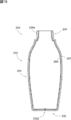
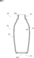
本発明の第3観点の一実施形態の積層剥離容器201は、図18Aに示すように、略有底円筒状の容器本体203と、ポンプ204とを備える。
1.全体構成
本発明の第3観点の一実施形態の積層剥離容器201は、図18Aに示すように、略有底円筒状の容器本体203と、ポンプ204とを備える。
容器本体203は、図19及び図20に示すように、有底筒状であり、胴部231及び底部232を有する収容部233と、収容部233から内容物を吐出する口部234とを備える。口部234の外面には、雄ねじ部234aが設けられている。また、本実施形態の容器本体203は、収容部233及び口部234において内袋206と外殻207とを備えており、内容物の減少に伴って内袋206が外殻207から離れることによって、内袋206が外殻207から離れて収縮するよう構成される。
内袋206は、容器外面側に設けられたEVOH層と、EVOH層の容器内面側に設けられた内面層と、EVOH層と内面層の間に設けられた接着層を備える。EVOH層を設けることでガスバリア性、及び外殻207からの剥離性を向上させることができる。ただし、接着層は省略してもよい。
外殻207は、例えば、低密度ポリエチレン、直鎖状低密度ポリエチレン、高密度ポリエチレン、ポリプロピレン、エチレン-プロピレン共重合体及びその混合物などで構成される。
ポンプ204は、図21に示すように、容器本体203内へ外気を導入させずに内容物を容器本体203から排出させるように構成されている。ポンプ204は、本体部241と、ピストン部242と、ノズル243と、チューブ244とを備える。本体部241は、筒部241aと、シリンダ部241bとを備える。筒部241aの内面には、容器本体203の口部234の雄ねじ部234aに螺合される雌ねじ部(図示せず)が設けられている。シリンダ部241bは、その下部が口部234内に挿入される。シリンダ部241bの外径は、口部234の内径とほぼ一致している。シリンダ部241bは、筒状であり、ピストン部242がシリンダ部241b内で摺動可能になっている。シリンダ部241bの内部空間は、ノズル243及びチューブ244に連通されている。シリンダ部241bの内部空間には、弾性部材と弁で構成されるポンプ機構が内蔵されている。ピストン部242を摺動させてポンプ機構を作動させることによって、チューブ244を通じて吸い上げた内容物をノズル243から排出することが可能になっている。
2.底部232の構成
以下、容器本体203の底部232の構成について、図22A~図23Bを用いて具体的に説明する。本実施形態の底部232は、図22A、図22B及び図18B、図19等にも示すように、その中央部分にピンチオフ部232pを備える。ピンチオフ部232pは、後述する積層パリソンPの下端を分割金型202X,202Yの食い切り部221X,221Y(図24A参照)で挟んで潰すことによって形成される帯状の構造である。また、底部232は、上述したように内袋206と外殻207の二重構造となっており、図23Aに示す内袋底部260と、図23Bに示す外殻底部270が嵌り合って構成される。
以下、容器本体203の底部232の構成について、図22A~図23Bを用いて具体的に説明する。本実施形態の底部232は、図22A、図22B及び図18B、図19等にも示すように、その中央部分にピンチオフ部232pを備える。ピンチオフ部232pは、後述する積層パリソンPの下端を分割金型202X,202Yの食い切り部221X,221Y(図24A参照)で挟んで潰すことによって形成される帯状の構造である。また、底部232は、上述したように内袋206と外殻207の二重構造となっており、図23Aに示す内袋底部260と、図23Bに示す外殻底部270が嵌り合って構成される。
内袋底部260は、図22A及び図23Aに示すように、ピンチオフ部232pにおいて、外側に突出する内袋突出部261を有する。また、外殻底部270は、図23A及び図23Bに示すように、ピンチオフ部232pにおいて、内袋突出部261を挟む挟持部271を有する。内袋突出部261と挟持部271の間には、外気導入孔208が設けられる(図22A、図23B及び図18B参照)。なお、本実施形態では、内袋突出部261及び挟持部271は底部232から突出していないが、底部232から突出させる構成としても良い。また、容器本体203の成形直後は内袋突出部261と挟持部271がくっついていて外気導入孔208が設けられていない。しかしながら、内袋突出部261と挟持部271は剥離されやすいので、内袋突出部261と挟持部271が剥離されるように衝撃やねじり力などを加えることによって、内袋突出部261と挟持部271を剥離させてその間に外気導入孔208を形成することができる。容器本体203は、外気導入孔208を有していることで、内容物の減少に伴って外殻207と内袋206の間に外気を導入し、内袋206のみを収縮させることが可能となっている。
加えて、本実施形態の容器本体203は、図22A及び図22B等に示すように、ピンチオフ部232pの長手方向端部に、内袋206と外殻207とが係合する係合部としての肉溜まり209が形成されている。具体的には、図22B及び図23Aに示すように、肉溜まり209において、内袋206(内袋底部260)は、径方向外側に突出する一対の凸部262を備える。また、肉溜まり209において、外殻207(外殻底部270)は、図22B及び図23Bに示すように、凸部262と係合する一対の凹部272を備える。本実施形態の容器本体203は、肉溜まり209においてこのように内袋206の凸部262と外殻207の凹部272とが係合しているため、内容物の減少に伴って内袋206が収縮しても、底部232から内袋206が簡単に脱離しないようになっている。なお、本実施形態の凸部262と凹部272とは、後述するブロー成形により一体的に成形されるものであり、凸部262と凹部272とは密接に嵌り合う形状となっている。
凸部262は、図22Bに示すように、その長手方向における突出量d1が底部232の中心Xから凸部262の先端までの長手方向における長さd2の0.15倍以上となるよう形成される。d1/d2の比は、好ましくは、0.18以上であり、より好ましくは、0.20以上である。また、d1/d2の比は、例えば0.15~0.30であり、より好ましくは、0.20~0.25である。具体的には例えば、0.15,0.16,0.17,0.18,0.19,0.20,0.21,0.22,0.23,0.24,0.25,0.26,0.27,0.28,0.29,0.30であり、ここで例示した数値の何れか2つの間の範囲内であってもよい。なお、「凸部262の長手方向における突出量d1」は、図22Bに示すように、ピンチオフ部232pにおける内袋底部260の断面において、内袋底部260が最もくびれた位置からの突出量と規定される。この突出量d1の長さは、具体的には1.5mm以上となるよう形成される。突出量d1は、好ましくは2.0mm以上である。また、突出量d1は、2.0mm~6.0mmとすることが好ましく、2.5mm~5.5mmとすることがより好ましく、3.5mm~4.5mmとすることがさらに好ましい。また、突出量d1の具体的な値は、例えば2.0,2.1,2.2,2.3,2.4,2.5,2.6,2.7,2.8,2.9,3.0,3.1,3.2,3.3,3.4,3.5,3.6,3.7,3.8,3.9,4.0,4.1,4.2,4.3,4.4,4.5,4.6,4.7,4.8,4.9,5.0,5.1,5.2,5.3,5.4,5.5,5.6,5.7,5.8,5.9,6.0であり、ここで例示した数値の何れか2つの間の範囲内であってもよい。なお、本実施形態の凸部262の先端は、図22Aに示すように、内袋206の底面の縁と径方向において略同一の位置まで突出している。ただし、内袋206の底面の縁よりも外側に突出する構成とすることも可能である。また、凸部262の突出量d1が十分に確保できる形状であれば、凸部262の先端が内袋206の底面の縁よりも内側の位置にとどまっていても良い。
3.製造方法
次に、図24A~図26Bを用いて、上述した積層剥離容器201の製造方法、特に、ブロー成形工程について説明する。
次に、図24A~図26Bを用いて、上述した積層剥離容器201の製造方法、特に、ブロー成形工程について説明する。
本実施形態において、容器本体203は、図24A及び図24Bに示すように、押出機205から押し出された筒状の積層パリソンPをブロー成形することによって形成される。積層パリソンPは、溶融状態でダイス205a(ダイヘッド)から押出され、これがブロー成形金型202の一対の分割金型202X,202Yによって型締めされる。分割金型202X,202Yは、胴部231、底部232、口部234などの容器本体203の各種形状がブロー成形品に形成されるようなキャビティー形状を有する。
ここで、図24Aに示すように、積層パリソンを押し出すダイス205aのダイス径、すなわちダイス205aから押し出される積層パリソンPの直径d3は、分割金型202X,202Yの内径のうち底部を形成する部分の内径、すなわち底部232(底面)の直径d4の2/π倍以下とされる。このような条件とすることで、型締めにより積層パリソンPが円筒形の状態から平らに押しつぶされても、押しつぶされた積層パリソンPの幅である折り径(成形後のピンチオフ部232pの幅とほぼ一致する)が容器本体203の底部232を形成する部分の内径d4よりも小さくなる。その結果、押しつぶされた積層パリソンPは容器内部においてブロー時に径方向外側へも流動することができるため、肉溜まり209が形成されやすくなる。d3/d4の比は、例えば0.1~0.63であり、より好ましくは、0.19~0.42である。d3/d4の比は、具体的には例えば、0.19,0.20,0.21,0.22,0.23,0.24,0.25,0.26,0.27,0.28,0.29,0.30,0.31,0.32,0.33,0.34,0.35,0.36,0.37,0.38,0.39,0.40,0.41,0.42であり、ここで例示した数値の何れか2つの間の範囲内であってもよい。
また、本実施形態において、積層パリソンPの直径d3は、図24Bに示すように、ブロー成形金型202の内径のうち容器本体203の口部234を形成する部分の内径d5よりもやや小さい径に設定される。d3/d5の比は、例えば0.6~0.9であり、より好ましくは、0.7~0.8である。また、d3/d5の比は、具体的には例えば、0.70,0.71,0.72,0.73,0.74,0.75,0.76,0.77,0.78,0.79,0.80であり、ここで例示した数値の何れか2つの間の範囲内であってもよい。口部234を形成する部分の内径d5に対して積層パリソンPの直径d3が太すぎると、型締め時にバリ噛み等が発生するおそれが生じ、また、積層パリソンPの直径d3が細すぎるとブロー比が大きくなりすぎて成形が困難となる。しかしながら、d3/d5の比を上記の値とすることで、口部234を好適に成形することができる。
以下、ブロー成形金型202による容器本体203の底部232付近の形状の成形について詳細に説明する。図24Aに示すように、ブロー成形金型202の分割金型202X,202Yは、それぞれ食い切り部221X,221Yを備える。また、ブロー成形金型202は、図24A~図25Bに示すように、食い切り部221X,221Yの下方にコンプレッション部222を備えている。コンプレッション部222は、分割金型202X,202Yにより形成され、型締め時に積層パリソンPを圧縮するものである。
本実施形態において、コンプレッション部222は、図24B及び図25Bに示すように、食い切り部221X,221Yの長手方向両端部近傍の位置に構成される第1コンプレッション領域222aと、第1コンプレッション領域222aの間の位置に構成される第2コンプレッション領域222bとを備える。そして、第1コンプレッション領域222aの型締め時における幅d6は、第2コンプレッション領域の型締め時における幅d7よりも狭くなっている。第1コンプレッション領域222aの型締め時における幅d6は、積層パリソンPの肉厚d8(図26A参照)以下とすることが好ましい。第1コンプレッション領域222aの型締め時における幅d6は、1mm以下とすることが好ましく、0.2mm以下とすることがより好ましい。また、幅d6は、金型同士が完全には当接しない間隔を有していることが好ましく、例えば0.01mm以上とすることが好ましい。幅d6の値は、例えば、0.01mm~1.00mmであり、好ましくは、0.05mm~0.20mmである。具体的には例えば、0.05,0.06,0.07,0.08,0.09,0.10,0.11,0.12,0.13,0.14,0.15,0.16,0.17,0.18,0.19,0.20mmであり、ここで例示した数値の何れか2つの間の範囲内であってもよい。一方、第2コンプレッション領域222bの型締め時における幅d7は、積層パリソンPの肉厚d8の2倍以下とすることが好ましい。また、幅d7は、10mm以下とすることが好ましく、8mm以下とすることがより好ましい。また、幅d7の値は、例えば1.0mm~6.0mmであり、より好ましくは、2.0mm~5.0mmであり、さらに好ましくは、3.0mm~4.0mmである。具体的には例えば、1.0,1.1,1.2,1.3,1.4,1.5,1.6,1.7,1.8,1.9,2.0,2.1,2.2,2.3,2.4,2.5,2.6,2.7,2.8,2.9,3.0,3.1,3.2,3.3,3.4,3.5,3.6,3.7,3.8,3.9,4.0,4.1,4.2,4.3,4.4,4.5,4.6,4.7,4.8,4.9,5.0,5.1,5.2,5.3,5.4,5.5,5.6,5.7,5.8,5.9,6.0mmであり、ここで例示した数値の何れか2つの間の範囲内であってもよい。
ここで、図26A~図26Cは、以上のような構成のブロー成形金型202に対して積層パリソンPを垂下させ、一対の分割金型202X,202Yを徐々に閉じていく際の様子を示すものである。図26Aの型締め前の状態から分割金型202X,202Yを閉じていくと、分割金型202X,202Yの食い切り部221X,221Yにより円筒状の積層パリソンPが内向きに押圧され、図26Bに示すように、まず積層パリソンPの内面(内袋206を形成する層)同士が当接する。この状態からさらに分割金型202X,202Yを閉じると、食い切り部221X,221Y及びコンプレッション部222により積層パリソンPが圧縮される。そして、図26Cに示すように金型が完全に閉じられることで、積層パリソンPは食い切り部221X,221Yにより2つに分離され、容器側においてピンチオフ部232pが形成される。
以上のように型締めを行った後は、容器本体203の口部234側の開口部にブローノズルを挿入し、型締めを行った状態で分割金型のキャビティー内にエアーを吹き込む。その後、分割金型を開いて、ブロー成形品を取り出し、ピンチオフ部232pの下側の部分に形成された下バリを除去する。そして、以上のように成形された成形品に対し、既知である内層予備剥離工程、上述した外気導入孔208の形成工程等を行い、容器本体203を完成させる。最後に、ポンプ204を容器本体203の口部234に装着することで、本実施形態の積層剥離容器201が完成する。
なお、図26B~図26Cに示すように分割金型202X,202Yを閉じていくと、積層パリソンPは徐々に圧縮される。この際、本実施形態においては、ブロー成形金型202がコンプレッション部222を有していることから、積層パリソンPは、食い切り部221X,221Yの上方(容器内側)よりも下方(容器外側)がより圧縮される。したがって、押しつぶされた積層パリソンPは、空間の広い容器内側方向(図26Bの矢印参照)に流動しやすくなっている。
しかも、本実施形態のコンプレッション部222は、第1コンプレッション領域222aと第2コンプレッション領域222bとを備えており、食い切り部221X,221Yの長手方向両端部近傍の第1コンプレッション領域222aの幅d6が第2コンプレッション領域222bの幅d7より狭く構成されている。これにより、コンプレッション部222により押しつぶされる積層パリソンPが横方向(食い切り部221X,221Yの長手方向、図24Bにおける左右方向)に広がることが抑制される。したがって、積層パリソンPは縦方向に移動してキャビティー内に押し戻され、積層パリソンPがより容器内側方向に流動しやすくなっている。そして、コンプレッション部222により積層パリソンPを押し戻した状態でエアーを吹き込みブロー成形を行うことで、肉溜まり209を好適に形成し、さらに、内袋206を外殻207へ食い込ませることが可能となっている。その結果、内袋206の凸部262の突出量d1を大きくすることができ、外殻207の凹部272との嵌り合いを強固にし、底部232からの内袋206の脱離を抑制することが可能となっている。
なお、従来の製造方法においても、コンプレッション部222により積層パリソンPを圧縮することはなされていた。しかしながら、従来の製造方法ではコンプレッション部222の幅を一定としていたため、内袋206の凸部262の突出量d1を十分得ることができなかった。この点、本実施形態の製造方法では、コンプレッション部222を上述した第1コンプレッション領域222aと第2コンプレッション領域222bとから構成したことにより、突出量d1を増加させることが可能となった。これにより、凸部262の長手方向における突出量d1と底部232の中心Xから凸部262の先端までの長手方向における長さd2との比d1/d2も、上述したように増加させることが可能となっている。(図22B参照)。
また、本実施形態の積層剥離容器201は、上述したように、肉溜まり209において内袋206の凸部262が外殻207の凹部272と係合しているため、内袋206が底部232から脱離しにくくなっているが、内袋206が全く脱離しない構成となっているわけではない。すなわち、内袋206の凸部262は外殻207の凹部272と係合しているだけであるため、積層剥離容器201内の内容物の残量が僅かになり、内袋206の収縮量が大きくなると、内袋206の変形により凸部262と凹部272の係合が解除されることになる。その結果、内袋206がより自由に変形できるようになり、ポンプ204の吸引によりチューブ244の端部に内容物を集め、内容物を最後まで排出することが可能となっている。
4.変形例
なお、第3観点の発明は、以下の態様でも実施可能である。
・上述した実施形態では、図25A及び図25Bに示すように、ブロー成形金型202の一対の分割金型202X,202Yは、第1コンプレッション領域222aの外側位置において完全に当接する構成であった。しかしながら、本発明のブロー成形金型202は、このような構成に限られない。すなわち、図27Aに示すように、第1コンプレッション領域222aが金型の端部まで連続する構成とすることも可能である。また、図27Bに示すように、第1コンプレッション領域222aよりも外側の領域(すなわち、型締め時に積層パリソンPが到達しない位置)では、一対の分割金型202X,202Yの間隙が第1コンプレッション領域222aの幅d6よりも大きくなる構成とすることも可能である。
・上述した実施形態では、積層剥離容器201がポンプ204により内容物を排出する構成となっていたが、容器本体203をスクイズすることで内容物を吐出する構成とすることも可能である。
・上記実施形態では、外気導入孔208を底部232に設けていたが、胴部231に設けることも可能である。また、この場合において、外気導入孔208に弁部材を設けることも好適である。
(第1観点)1:積層剥離容器、2:容器本体、3:弁部材、4:キャップ、5:収容部、5a:弁部材取付凹部、5b:空気流通溝、6:口部、6a:雄ねじ部、7:肩部、8:空気導入孔、12:外殻、14:内袋、21:上げ部、21a:傾斜部、22:ストッパ部、22f:テーパ面、22g:テーパ面、23:凹部、34:パッキン、41:キャップ本体、42:ヒンジ、43:キャップカバー、44:主キャップ部材、44a:外側筒部、44b:内側筒部、44c:環状部、44d:雌ねじ部、44e:拡径部、44f:突起、44g:弁座、45:逆止弁、45a:弁体、45b:弾性片、46:吐出部材、46a:吐出口、G:空間、H1:高さ、H2:高さ、T1:突出幅、T2:突出幅、W1:幅、W2:幅
(第2観点)
101:二重容器、102:リーク検査装置、103:ヘッド、104:電磁弁、105:減圧系統、106:加圧系統、107:収容部、107a:胴部、107b:底部、107d:喰切部、108:配管、108a:配管、108b:配管、108c:配管、109:口部、112:外殻、114:内袋、114a:底部、114b:部位、114c:部位、115:外気導入部、131:ヘッドベース、131a:貫通孔、131b:収容凹部、132:パッキン、132a:貫通孔、133:挿入部材、133a:棒状部、133a1:先端、133b:フランジ部、133c:貫通孔、133d:吸込口、134:パッキン、134a:貫通孔、151:流量計、152:圧力計、153:レギュレータ、154:真空ポンプ、161:スピードコントローラ、162:レギュレータ、163:コンプレッサ
(第3観点)
201:積層剥離容器、202:ブロー成形金型、202X:分割金型、202Y:分割金型、203:容器本体、204:ポンプ、205:押出機、205a:ダイス、206:内袋、207:外殻、208:外気導入孔、209:肉溜まり、221X:切り部、221Y:切り部、222:コンプレッション部、222a:第1コンプレッション領域、222b:第2コンプレッション領域、231:胴部、232:底部、232p:ピンチオフ部、233:収容部、234:口部、234a:雄ねじ部、241:本体部、241a:筒部、241b:シリンダ部、242:ピストン部、243:ノズル、244:チューブ、260:内袋底部、261:内袋突出部、262:凸部、270:外殻底部、271:挟持部、272:凹部、P:積層パリソン、R:領域、X:中心、d1:突出量、d2:底部の中心から凸部の先端までの長さ、d3:積層パリソンPの直径、d4:底部の直径、d5:口部を形成する部分の内径、d6:第1コンプレッション領域の幅、d7:第2コンプレッション領域の幅、d8:積層パリソンPの肉厚
Claims (22)
- 容器本体及びキャップを有するキャップ付き容器であって、
前記キャップは雌ねじ部を備え、前記容器本体はその口部に前記雌ねじ部と螺合する雄ねじ部を備えており、
前記キャップは、前記雌ねじ部よりも前記容器本体側の位置に突起を備え、
前記容器本体は、前記突起と係合して前記キャップの緩みを規制する乗り上げ部と、当該乗り上げ部よりもねじの締結方向側に位置し前記キャップのオーバーランを規制するストッパ部とを備えている、キャップ付き容器。 - 請求項1に記載のキャップ付き容器であって、
前記ストッパ部の高さと、当該ストッパ部の径方向の突出幅の少なくとも一方を、前記乗り上げ部のものよりも大きくした、キャップ付き容器。 - 請求項1又は請求項2に記載のキャップ付き容器であって、
前記突起は周方向における対向する2箇所に設けられ、
前記乗り上げ部及び前記ストッパ部も、周方向における対向する2箇所にそれぞれ設けられている、キャップ付き容器。 - 請求項3に記載のキャップ付き容器であって、
一方の突起のオーバーランを規制するストッパ部の高さは、他方の突起と干渉しない略最大の高さとされる、キャップ付き容器。 - 請求項4に記載のキャップ付き容器であって、
前記ストッパ部は、周方向における前記ねじの締結方向側に、前記他方の突起との干渉を防止するテーパ面を有する、キャップ付き容器。 - 請求項1~請求項5のいずれかに記載のキャップ付き容器であって、
前記容器本体は、外殻と内袋とを有し且つ内容物の減少に伴って前記内袋が収縮するよう構成される、キャップ付き容器。 - 請求項6に記載のキャップ付き容器であって、
前記外殻には空気導入孔が形成されており、
前記乗り上げ部及び前記ストッパ部は、前記空気導入孔と周方向における略同一の位置又は周方向において対向する位置に設けられる、キャップ付き容器。 - 二重容器のリーク検査方法であって、
前記二重容器は、外殻と内袋とを有し且つ内容物の減少に伴って前記内袋が収縮するように構成され、
前記方法は、前記内袋の内部の減圧時に得られるデータに基づいて前記内袋にピンホールが存在するか否かの判定を行う工程を備える、方法。 - 請求項8に記載の方法であって、
前記判定は、前記減圧時に前記内袋から吸い出されるエアーの流量に基づいて行われる、方法。 - 請求項8又は請求項9に記載の方法であって、
前記減圧は、前記二重容器の口部から前記内袋内に棒状部が挿入された状態で行われる、方法。 - 二重容器の予備剥離方法であって、
前記二重容器は、外殻と内袋とを有し且つ内容物の減少に伴って前記内袋が収縮するように構成され、
前記方法は、前記二重容器の口部から前記内袋内に棒状部が挿入された状態で、前記内袋の内部を減圧することによって前記内袋を前記外殻から剥離する工程を備える、方法。 - 請求項10又は請求項11に記載の方法であって、
前記二重容器の全高をHとし、前記棒状部のうち前記内袋内に挿入されている部位の長さをLとすると、L/Hは、0.40以上である、方法。 - 請求項10~請求項12の何れか1つに記載の方法であって、
前記口部の内周面の内接円径をD1とし、前記棒状部の外接円径をD2とすると、D2/D1は、0.30以上である、方法。 - 請求項10~請求項13の何れか1つに記載の方法であって、
前記減圧は、前記棒状部に設けられた吸込口を通じて行われる、方法。 - 請求項14に記載の方法であって、
前記吸込口は、前記棒状部の先端に設けられる、方法。 - 外殻と内袋とを有し且つ内容物の減少に伴って前記内袋が収縮する積層剥離容器であって、
内容物を収容する収容部と、当該収容部の底部に形成されるピンチオフ部とを備え、
前記ピンチオフ部の長手方向の端部に、前記外殻と前記内袋が係合する係合部を備え、
前記内袋は、前記係合部において、前記長手方向の外側に突出する凸部を備え、
前記外殻は、前記係合部において、前記凸部と係合する凹部を備えており、
前記凸部の前記長手方向における突出量は、前記底部の中心から前記凸部の先端までの前記長手方向における長さの0.15倍以上である、積層剥離容器。 - 請求項16に記載の積層剥離容器であって、
前記凸部の先端は、前記内袋の底面の縁と径方向において略同一の位置まで突出するか又は、前記内袋の底面の縁よりも外側に突出している、積層剥離容器。 - 前記ピンチオフ部に、前記外殻と前記内袋の間の空間に外気を導入する外気導入孔を備える、請求項16又は請求項17記載の積層剥離容器。
- 外殻と内袋とを有し且つ内容物の減少に伴って前記内袋が収縮する積層剥離容器の製造方法であって、
円筒状の積層パリソンを用いたブロー成形工程を備え、
前記金型は、前記積層剥離容器のピンチオフ部を成形する食い切り部の近傍に、型締め前に前記積層パリソンを圧縮して当該積層パリソンを容器内側方向に流動させるコンプレッション部を備え、
前記コンプレッション部は、前記食い切り部の長手方向両端部近傍の位置に構成される第1コンプレッション領域と、当該第1コンプレッション領域の間の位置に構成される第2コンプレッション領域とを備え、
前記第1コンプレッション領域の型締め時における幅は、第2コンプレッション領域の型締め時における幅よりも狭い、積層剥離容器の製造方法。 - 請求項19に記載の積層剥離容器の製造方法であって、
前記積層パリソンを押し出すダイス径は、前記金型の内径のうち底部を形成する部分の内径の2/π倍以下である、積層剥離容器の製造方法。 - 請求項19又は請求項20に記載の積層剥離容器の製造方法であって、
前記第1コンプレッション領域の型締め時における幅は、前記積層パリソンの肉厚以下であり、
前記第2コンプレッション領域の型締め時における幅は、前記積層パリソンの肉厚の2倍以下である、積層剥離容器の製造方法。 - 請求項19~請求項21の何れかに記載の積層剥離容器の製造方法であって、
前記第2コンプレッション領域は、型締め時における幅が5mm以下である、積層剥離容器の製造方法。
Priority Applications (1)
| Application Number | Priority Date | Filing Date | Title |
|---|---|---|---|
| CN201980064280.3A CN112770978B (zh) | 2018-11-30 | 2019-11-26 | 带盖容器 |
Applications Claiming Priority (6)
| Application Number | Priority Date | Filing Date | Title |
|---|---|---|---|
| JP2018-224637 | 2018-11-30 | ||
| JP2018224637A JP7212250B2 (ja) | 2018-11-30 | 2018-11-30 | キャップ付き容器 |
| JP2019007950A JP7137075B2 (ja) | 2019-01-21 | 2019-01-21 | 積層剥離容器 |
| JP2019-007950 | 2019-01-21 | ||
| JP2019-020958 | 2019-02-07 | ||
| JP2019020958A JP7323765B2 (ja) | 2019-02-07 | 2019-02-07 | 二重容器のリーク検査方法及び予備剥離方法 |
Publications (1)
| Publication Number | Publication Date |
|---|---|
| WO2020111024A1 true WO2020111024A1 (ja) | 2020-06-04 |
Family
ID=70853487
Family Applications (1)
| Application Number | Title | Priority Date | Filing Date |
|---|---|---|---|
| PCT/JP2019/046063 WO2020111024A1 (ja) | 2018-11-30 | 2019-11-26 | キャップ付き容器、二重容器のリーク検査方法、積層剥離容器及びその製造方法 |
Country Status (3)
| Country | Link |
|---|---|
| CN (1) | CN112770978B (ja) |
| TW (1) | TWI827742B (ja) |
| WO (1) | WO2020111024A1 (ja) |
Citations (8)
| Publication number | Priority date | Publication date | Assignee | Title |
|---|---|---|---|---|
| JPH0731640U (ja) * | 1993-11-19 | 1995-06-13 | 吉田工業株式会社 | 位置合せ容器 |
| JPH08151061A (ja) * | 1994-11-30 | 1996-06-11 | Yoshino Kogyosho Co Ltd | キャップ付き容器 |
| JP3303234B2 (ja) * | 1997-09-17 | 2002-07-15 | 株式会社吉野工業所 | 二重ブロー成形壜体の内容器リーク検査方法 |
| US20030146183A1 (en) * | 2002-02-04 | 2003-08-07 | Rexam Medical Packaging Inc. | Rotary seal for closure with on-stop |
| JP2006306460A (ja) * | 2005-04-28 | 2006-11-09 | Kyoraku Co Ltd | 密封容器の首部の緩衝構造 |
| JP2013199296A (ja) * | 2012-03-23 | 2013-10-03 | Daiwa Can Co Ltd | 樹脂容器 |
| JP2016159935A (ja) * | 2015-02-27 | 2016-09-05 | 株式会社吉野工業所 | 二重容器 |
| JP2017057009A (ja) * | 2015-09-15 | 2017-03-23 | 天龍化学工業株式会社 | ねじ蓋式容器 |
Family Cites Families (11)
| Publication number | Priority date | Publication date | Assignee | Title |
|---|---|---|---|---|
| JP2007176543A (ja) * | 2005-12-27 | 2007-07-12 | Kao Corp | キャップ付き容器 |
| KR101210435B1 (ko) * | 2010-11-11 | 2012-12-10 | (주)연우 | 안전캡 |
| EP2468654B1 (en) * | 2010-12-23 | 2015-03-04 | Obrist Closures Switzerland GmbH | Closure for a container |
| US9862528B2 (en) * | 2013-07-12 | 2018-01-09 | Tokan Kogyo Co., Ltd. | Cap assembly and method for capping same |
| TWI642600B (zh) * | 2014-02-12 | 2018-12-01 | 日商京洛股份有限公司 | 積層剝離容器,其針孔檢查方法,及其加工方法 |
| JP6761159B2 (ja) * | 2014-11-19 | 2020-09-23 | キョーラク株式会社 | 積層剥離容器 |
| US10723500B2 (en) * | 2014-12-09 | 2020-07-28 | Kyoraku Co., Ltd. | Delamination container, method for attaching cap to delamination container, and method for manufacturing delamination container |
| JP6675069B2 (ja) * | 2015-05-28 | 2020-04-01 | キョーラク株式会社 | 二重容器 |
| EP3305673B1 (en) * | 2015-05-28 | 2019-09-25 | Kyoraku Co., Ltd. | Double container |
| CA3220349A1 (en) * | 2015-09-01 | 2017-03-09 | Franklin Fueling Systems, Inc. | Tank maintenance access chamber |
| CN206590291U (zh) * | 2017-02-23 | 2017-10-27 | 东莞市鑫宇制罐有限公司 | 一种螺旋铁罐 |
-
2019
- 2019-11-26 WO PCT/JP2019/046063 patent/WO2020111024A1/ja active Application Filing
- 2019-11-26 CN CN201980064280.3A patent/CN112770978B/zh active Active
- 2019-11-28 TW TW108143356A patent/TWI827742B/zh active
Patent Citations (8)
| Publication number | Priority date | Publication date | Assignee | Title |
|---|---|---|---|---|
| JPH0731640U (ja) * | 1993-11-19 | 1995-06-13 | 吉田工業株式会社 | 位置合せ容器 |
| JPH08151061A (ja) * | 1994-11-30 | 1996-06-11 | Yoshino Kogyosho Co Ltd | キャップ付き容器 |
| JP3303234B2 (ja) * | 1997-09-17 | 2002-07-15 | 株式会社吉野工業所 | 二重ブロー成形壜体の内容器リーク検査方法 |
| US20030146183A1 (en) * | 2002-02-04 | 2003-08-07 | Rexam Medical Packaging Inc. | Rotary seal for closure with on-stop |
| JP2006306460A (ja) * | 2005-04-28 | 2006-11-09 | Kyoraku Co Ltd | 密封容器の首部の緩衝構造 |
| JP2013199296A (ja) * | 2012-03-23 | 2013-10-03 | Daiwa Can Co Ltd | 樹脂容器 |
| JP2016159935A (ja) * | 2015-02-27 | 2016-09-05 | 株式会社吉野工業所 | 二重容器 |
| JP2017057009A (ja) * | 2015-09-15 | 2017-03-23 | 天龍化学工業株式会社 | ねじ蓋式容器 |
Also Published As
| Publication number | Publication date |
|---|---|
| TWI827742B (zh) | 2024-01-01 |
| CN112770978A (zh) | 2021-05-07 |
| CN112770978B (zh) | 2022-12-16 |
| TW202030462A (zh) | 2020-08-16 |
Similar Documents
| Publication | Publication Date | Title |
|---|---|---|
| US11040865B2 (en) | Container and set of preforms for forming a container | |
| EP1422160B1 (en) | Pouring vessel | |
| US10822135B2 (en) | Delaminatable container | |
| KR101493534B1 (ko) | 다이렉트 블로우 성형방법에 의한 합성수지제 이중 용기 | |
| KR100338994B1 (ko) | 적층박리용기와 그 관련기술 | |
| JP6112385B2 (ja) | ブロー成形容器及びその製造方法 | |
| EP1277669A1 (en) | Tyre puncture sealant set | |
| JP6547242B2 (ja) | 容器 | |
| JP2006335398A (ja) | 内側層が剥離可能な積層容器その成形方法 | |
| TW201917065A (zh) | 層疊剝離容器 | |
| KR20050052413A (ko) | 주출용기 | |
| WO2020111024A1 (ja) | キャップ付き容器、二重容器のリーク検査方法、積層剥離容器及びその製造方法 | |
| JP2019081591A (ja) | 二重容器用キャップ | |
| CN108698731B (zh) | 双层容器和其制造方法 | |
| CN110831864B (zh) | 层叠剥离容器及层叠剥离容器的漏气检查方法 | |
| JP2005111094A (ja) | フィルター付き吐出容器 | |
| JP2014091531A (ja) | ブロー成形容器 | |
| US20030173537A1 (en) | Valve stop | |
| JP2020023352A (ja) | 二重容器 | |
| JP5878000B2 (ja) | 吐出容器 | |
| JP7137075B2 (ja) | 積層剥離容器 | |
| JP4156283B2 (ja) | 液体容器 | |
| JP2021127164A (ja) | 二重容器 | |
| JP2009023224A (ja) | パンクシーリング剤送給、抜取りユニット |
Legal Events
| Date | Code | Title | Description |
|---|---|---|---|
| 121 | Ep: the epo has been informed by wipo that ep was designated in this application |
Ref document number: 19891528 Country of ref document: EP Kind code of ref document: A1 |
|
| NENP | Non-entry into the national phase |
Ref country code: DE |
|
| 122 | Ep: pct application non-entry in european phase |
Ref document number: 19891528 Country of ref document: EP Kind code of ref document: A1 |