WO2020110339A1 - 光学ユニット - Google Patents
光学ユニット Download PDFInfo
- Publication number
- WO2020110339A1 WO2020110339A1 PCT/JP2019/016102 JP2019016102W WO2020110339A1 WO 2020110339 A1 WO2020110339 A1 WO 2020110339A1 JP 2019016102 W JP2019016102 W JP 2019016102W WO 2020110339 A1 WO2020110339 A1 WO 2020110339A1
- Authority
- WO
- WIPO (PCT)
- Prior art keywords
- flexible wiring
- wiring board
- optical unit
- optical
- axis direction
- Prior art date
- Legal status (The legal status is an assumption and is not a legal conclusion. Google has not performed a legal analysis and makes no representation as to the accuracy of the status listed.)
- Ceased
Links
Images



Classifications
-
- G—PHYSICS
- G03—PHOTOGRAPHY; CINEMATOGRAPHY; ANALOGOUS TECHNIQUES USING WAVES OTHER THAN OPTICAL WAVES; ELECTROGRAPHY; HOLOGRAPHY
- G03B—APPARATUS OR ARRANGEMENTS FOR TAKING PHOTOGRAPHS OR FOR PROJECTING OR VIEWING THEM; APPARATUS OR ARRANGEMENTS EMPLOYING ANALOGOUS TECHNIQUES USING WAVES OTHER THAN OPTICAL WAVES; ACCESSORIES THEREFOR
- G03B5/00—Adjustment of optical system relative to image or object surface other than for focusing
-
- G—PHYSICS
- G02—OPTICS
- G02B—OPTICAL ELEMENTS, SYSTEMS OR APPARATUS
- G02B7/00—Mountings, adjusting means, or light-tight connections, for optical elements
- G02B7/02—Mountings, adjusting means, or light-tight connections, for optical elements for lenses
- G02B7/04—Mountings, adjusting means, or light-tight connections, for optical elements for lenses with mechanism for focusing or varying magnification
-
- H—ELECTRICITY
- H04—ELECTRIC COMMUNICATION TECHNIQUE
- H04N—PICTORIAL COMMUNICATION, e.g. TELEVISION
- H04N23/00—Cameras or camera modules comprising electronic image sensors; Control thereof
- H04N23/50—Constructional details
-
- H—ELECTRICITY
- H04—ELECTRIC COMMUNICATION TECHNIQUE
- H04N—PICTORIAL COMMUNICATION, e.g. TELEVISION
- H04N23/00—Cameras or camera modules comprising electronic image sensors; Control thereof
- H04N23/50—Constructional details
- H04N23/51—Housings
-
- H—ELECTRICITY
- H04—ELECTRIC COMMUNICATION TECHNIQUE
- H04N—PICTORIAL COMMUNICATION, e.g. TELEVISION
- H04N23/00—Cameras or camera modules comprising electronic image sensors; Control thereof
- H04N23/50—Constructional details
- H04N23/54—Mounting of pick-up tubes, electronic image sensors, deviation or focusing coils
-
- H—ELECTRICITY
- H04—ELECTRIC COMMUNICATION TECHNIQUE
- H04N—PICTORIAL COMMUNICATION, e.g. TELEVISION
- H04N23/00—Cameras or camera modules comprising electronic image sensors; Control thereof
- H04N23/57—Mechanical or electrical details of cameras or camera modules specially adapted for being embedded in other devices
-
- H—ELECTRICITY
- H05—ELECTRIC TECHNIQUES NOT OTHERWISE PROVIDED FOR
- H05K—PRINTED CIRCUITS; CASINGS OR CONSTRUCTIONAL DETAILS OF ELECTRIC APPARATUS; MANUFACTURE OF ASSEMBLAGES OF ELECTRICAL COMPONENTS
- H05K1/00—Printed circuits
- H05K1/18—Printed circuits structurally associated with non-printed electric components
- H05K1/189—Printed circuits structurally associated with non-printed electric components characterised by the use of flexible or folded printed circuits
-
- G—PHYSICS
- G03—PHOTOGRAPHY; CINEMATOGRAPHY; ANALOGOUS TECHNIQUES USING WAVES OTHER THAN OPTICAL WAVES; ELECTROGRAPHY; HOLOGRAPHY
- G03B—APPARATUS OR ARRANGEMENTS FOR TAKING PHOTOGRAPHS OR FOR PROJECTING OR VIEWING THEM; APPARATUS OR ARRANGEMENTS EMPLOYING ANALOGOUS TECHNIQUES USING WAVES OTHER THAN OPTICAL WAVES; ACCESSORIES THEREFOR
- G03B2205/00—Adjustment of optical system relative to image or object surface other than for focusing
- G03B2205/0007—Movement of one or more optical elements for control of motion blur
- G03B2205/0023—Movement of one or more optical elements for control of motion blur by tilting or inclining one or more optical elements with respect to the optical axis
-
- H—ELECTRICITY
- H05—ELECTRIC TECHNIQUES NOT OTHERWISE PROVIDED FOR
- H05K—PRINTED CIRCUITS; CASINGS OR CONSTRUCTIONAL DETAILS OF ELECTRIC APPARATUS; MANUFACTURE OF ASSEMBLAGES OF ELECTRICAL COMPONENTS
- H05K2201/00—Indexing scheme relating to printed circuits covered by H05K1/00
- H05K2201/05—Flexible printed circuits [FPCs]
- H05K2201/055—Folded back on itself
-
- H—ELECTRICITY
- H05—ELECTRIC TECHNIQUES NOT OTHERWISE PROVIDED FOR
- H05K—PRINTED CIRCUITS; CASINGS OR CONSTRUCTIONAL DETAILS OF ELECTRIC APPARATUS; MANUFACTURE OF ASSEMBLAGES OF ELECTRICAL COMPONENTS
- H05K2201/00—Indexing scheme relating to printed circuits covered by H05K1/00
- H05K2201/10—Details of components or other objects attached to or integrated in a printed circuit board
- H05K2201/10007—Types of components
- H05K2201/10121—Optical component, e.g. opto-electronic component
Definitions
- the present invention relates to an optical unit.
- Patent Document 1 discloses an optical unit including a movable module that holds an optical element, a fixed body that holds the movable module in a displaceable manner, and a flexible wiring board that is connected to the movable module.
- an object of the present invention is to downsize the optical unit while reducing the load applied to the flexible wiring board.
- the optical unit of the present invention rotatably supports the movable body with respect to the fixed body, the movable body including the optical module, the fixed body, and one or more directions intersecting the optical axis direction as the rotation axis direction.
- a support mechanism a flexible wiring board, one end of which is connected to a connection portion provided on the movable body, the flexible wiring board being disposed on the first intersecting direction side that intersects the optical axis direction with respect to the movable body; And a positioning portion that is arranged on the first intersecting direction side and that positions the other end of the flexible wiring board in the optical axis direction so that the flexible wiring boards overlap each other when viewed from the optical axis direction. It is bent, and the position of the rotating shaft in the optical axis direction is within a range from the connecting portion to the positioning portion.
- the flexible wiring board since the flexible wiring board is bent so as to be overlapped with each other when viewed from the optical axis direction, the flexible wiring board can be lengthened, and the flexible wiring board is improved in adaptability to displacement, and thus the flexible wiring board is applied.
- the load can be reduced.
- the length of the wiring area of the flexible wiring board in the optical axis direction in the optical axis direction from the connection portion to the positioning portion (Length), that is, the volume of the wiring area of the flexible wiring board can be reduced. Therefore, the optical unit can be downsized while reducing the load on the flexible wiring board.
- the bending direction of the flexible wiring board in the extending direction from the one end to the other end when viewed from the first intersecting direction is at least to the rotation axis side in the optical axis direction. It is preferable to include the bending direction. This is because the load applied to the flexible wiring board can be effectively reduced by bending the rotary shaft side.
- the flexible wiring board is bent a plurality of times, and the bending direction of the flexible wiring board in the extending direction when viewed from the first intersecting direction is the optical axis direction. It is preferable to include both the side of the rotation axis in and the side opposite to the side of the rotation axis in the optical axis direction.
- the length in the optical axis direction in the wiring area of the flexible wiring board is included. This is because it can be effectively shortened.
- the number of bends of the flexible wiring board is the number of bends to the rotation axis side in the optical axis direction and the number of bends to the side opposite to the rotation axis side in the optical axis direction.
- the flexible wiring board when viewed from a direction intersecting with the optical axis direction and the first intersecting direction, is a central portion of each bent portion of the flexible wiring substrate in the first intersecting direction. It is preferable to be bent so as to be symmetrical with respect to. This is because the flexible wiring board is bent so as to be symmetrical in the first intersecting direction, so that the deflection of the flexible wiring board in the first intersecting direction can be reduced.
- the flexible wiring board is bent an even number of times.
- the bending portion goes to the side closer to the movable body in the first intersecting direction by the bending portion at an odd number, Due to the bent portion of, the side faces toward the movable body in the first intersecting direction. That is, by setting the number of times of bending the flexible wiring board to an even number, the flexible wiring board can be easily arranged at a position away from the movable body, and the flexible wiring board can be easily arranged in a direction away from the movable body. The contact between the flexible wiring board and the movable body can be suppressed. Moreover, the degree of freedom of wiring can be increased.
- the position of the positioning portion in the optical axis direction is different from the position of the connecting portion in the optical axis direction. This is because the flexible wiring board can be easily configured to be long.
- the flexible wiring board has a branch region that branches in an extending direction from the one end to the other end. This is because the load applied to the flexible wiring board can be effectively reduced.
- the branch area is configured such that the flexible wiring board is symmetrical when viewed from the extending direction. This is because the load applied to the flexible wiring board can be reduced particularly effectively.
- the positioning portion is formed integrally with the fixed body. This is because the flexible wiring board can be accurately positioned by forming the positioning portion integrally with the fixed body.
- the positioning portion allows the flexible wiring board to move in the first intersecting direction.
- the load can be reduced by moving in the first intersecting direction. This is because the load applied to the flexible wiring board can be effectively reduced.
- the positioning section includes a cover that covers at least a part of the flexible wiring board. This is because it is possible to prevent the flexible wiring board from being damaged by coming into contact with other components.
- a bent holding portion that holds the bent portion is provided at the bent portion of the flexible wiring board.
- the wiring area of the flexible wiring board can be effectively reduced in size, and It is possible to suppress damage to the flexible wiring boards due to contact between the flexible wiring boards.
- a rotation drive mechanism for rotating the movable body with respect to the fixed body is provided, and the rotation drive mechanism is arranged at a position other than the first intersecting direction side with respect to the movable body.
- the rotation drive mechanism can be arranged on the side where the flexible wiring board is not formed, it is not necessary to enlarge the optical unit to suppress the contact between the rotation drive mechanism and the flexible wiring board, and the optical unit can be downsized. This is because
- the optical module has an image pickup device, and the image pickup device is arranged on the first intersecting direction side with respect to the rotation axis. This is because the flexible wiring board inside the fixed body can be shortened, the fixed body can be downsized, and the optical unit can be downsized.
- the optical unit of the present invention can reduce the size of the optical unit while reducing the load on the flexible wiring board.
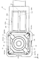
- FIG. 3 is a plan view of the optical unit according to the first embodiment of the present invention.
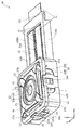
- FIG. 3 is a perspective view of the optical unit according to the first embodiment of the present invention.
- FIG. 3 is an exploded perspective view of the optical unit according to the first embodiment of the present invention.
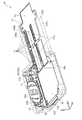
- FIG. 3 is a perspective view showing a fixed body of the optical unit according to the first embodiment of the present invention by making it transparent.
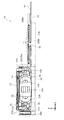
- FIG. 3 is a side view showing the fixed body of the optical unit according to the first embodiment of the present invention by making it transparent.
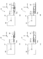
- It is a schematic diagram of the optical unit concerning Example 1 to Example 4 of the present invention.
- It is a schematic diagram of the optical unit concerning Example 5 to Example 8 of the present invention.
- It is a schematic diagram of an optical unit concerning Example 9 to 12 of the present invention.
- It is a schematic diagram of the optical unit concerning Example 13 to Example 16 of the present invention.
- It is a schematic diagram of the optical unit concerning Example 17 and Example 18 of the present invention.
- Example 1 First, the optical unit according to the first embodiment of the present invention will be described with reference to FIGS. 1 to 5 and FIG. 6A. 2 and 3, the alternate long and short dash line labeled L indicates the optical axis, the alternate long and short dash line labeled L1 indicates the first axis that intersects the optical axis, and the single dash point denoted by L2 is indicated.
- the chain line indicates the optical axis L and the second axis L2 that intersects the first axis L1.
- the R direction is the direction around the optical axis.
- the Z-axis direction is the optical axis direction
- the X-axis direction is the direction intersecting the optical axis, in other words the yawing axis direction
- the Y-axis direction is the direction intersecting the optical axis, in other words the pitching. Is the axial direction of.
- the configuration of the optical unit 10 according to the present embodiment will be described with reference to FIGS. 1 to 5.
- the optical unit 10 holds the movable body 14 including the optical module 12 and the movable body 14 in a displaceable state in a direction having the Y-axis direction as a rotation axis (pitching direction) and a direction having the X-axis direction as a rotation axis (yawing direction).
- the fixed body 16 is provided. Further, a rotation drive mechanism 18 that drives the movable body 14 in the pitching direction and the yawing direction, and a support mechanism 20 that supports the movable body 14 rotatably with respect to the fixed body 16 in the pitching direction and the yawing direction.
- the optical unit 10 is provided with the first support portion 19a that supports the movable body 14 so as to be rotatable about the first axis L1 in the first support portion extension portion 27a, and is fixed around the second axis L2.
- the gimbal mechanism 21 is provided with the second support portion 19b rotatably supported by the 16-side member in the second support portion extension portion 27b (see FIG. 3).
- the optical module 12 is formed in a substantially rectangular housing shape and is used as, for example, a thin camera mounted on a camera-equipped mobile phone, a tablet PC, or the like.
- the optical module 12 includes a lens 12a on the object side, and a housing 12b in the shape of a rectangular housing, and an optical device for capturing an image and the like are built in the housing 12b.
- the optical module 12 in the present embodiment has a pitching shake (rotational shake about the Y-axis direction as a rotation axis) and a yawing shake (rotation about the X-axis direction as a rotation axis) occurring in the optical module 12. It has a built-in actuator that corrects shakes in the direction of motion, and is configured to correct shakes in pitching and shakes in yawing.
- the optical module 12 has a configuration capable of correcting pitching shake and yawing shake.
- the present invention is not limited to this structure.
- one of pitching shake and yawing shake can be used. It may be configured such that only the correction is possible.
- the movable body 14 includes an optical module 12, a holder frame 22, and magnets 24A and 24B.
- the holder frame 22 is configured as a rectangular frame-shaped member that is provided so as to surround the front surface (the surface on the object side) on which the lens 12a of the optical module 12 is provided and the remaining four surfaces except the rear surface on the opposite side. ..
- the holder frame 22 of the present embodiment is configured such that the optical module 12 can be attached and detached as an example.
- Magnets 24A and 24B for correcting pitching and yawing are attached to the outer surfaces of the holder frame 22 by utilizing the two surfaces facing the fixed body 16.
- the fixed body 16 includes a fixed frame 28 and coils 32A and 32B.
- the fixed frame 28 includes a rectangular frame-shaped member 128 provided so as to surround at least three surfaces of the holder frame 22 of the movable body 14 in the optical axis direction (R direction), and along the X-axis direction. It is composed of a wall portion 228a extending outward, a wall portion 228b, and an extension portion 228 having a wall portion 228c.
- the wall portion 228a is a wall portion that covers a part of the front surface (surface on the subject side) and has the hole portion 13 formed therein.
- the wall portion 228b and the wall portion 228c are wall portions that cover the Y-axis direction.
- the region surrounded by the wall portion 228a, the wall portion 228b, and the wall portion 228c on the extending portion 228 side from the three directions is a space (the wall portion is not provided). ).
- the fixed body 16 of the present embodiment has a structure in which the flexible wiring board 51, which will be described later, can be covered with the wall portion 228a, the wall portion 228b, and the wall portion 228c from three directions.
- a positioning portion 52 (see FIG. 4) for positioning the position in the direction is provided.
- the extending portion 228 of this embodiment has no wall portion on the side facing the wall portion 228a. This is to improve workability when arranging the flexible wiring board 51 on the extension portion 228.
- the present invention is not limited to such a configuration, and a wall portion may be provided on the side facing the wall portion 228a, and a wall portion or the like that can be attached after the flexible wiring board 51 is arranged in the extension portion 228 is used. You can It goes without saying that the wall portion 228a may not be provided with the hole portion 13.
- the coils 32A and 32B are attached to the coil attachment portion 28a.
- the coil 32A and the coil 32B are configured as winding coils as an example, but may be a pattern substrate (coil substrate) in which the coils are incorporated in the substrate wiring as a pattern.
- the magnet 24A and the coil 32A and the magnet 24B and the coil 32B are opposed to each other.
- the pair of the magnet 24A and the coil 32A and the pair of the magnet 24B and the coil 32B constitute the rotary drive mechanism 18.
- the rotary drive mechanism 18 corrects the pitching and yawing of the movable body 14.
- the corrections for pitching and yawing are performed as follows.
- the shake is detected by a magnetic sensor (Hall element) (not shown), and the rotation drive mechanism 18 is driven based on the result.
- a shake detection sensor gyroscope
- the rotation drive mechanism 18 acts to correct the shake. That is, a current is applied to each of the coils 32A and 32B so as to move the movable body 14 in a direction in which the shake of the optical unit 10 is canceled out, and the shake is thereby corrected.
- the optical unit 10 of the present embodiment is provided with the rotary drive mechanism 18 for rotating the movable body 14 with respect to the fixed body 16 about the pitching axis direction and the yawing axis direction as rotation axes.
- the rotation drive mechanism 18 is arranged at a position other than the side where the flexible wiring board 51 is arranged in the X-axis direction with respect to the movable body 14 (the first intersecting direction side that intersects the optical axis direction).
- the rotary drive mechanism 18 can be arranged on the side where the flexible wiring board 51 is not formed, it is not necessary to enlarge the optical unit 10 in order to suppress the contact between the rotary drive mechanism 18 and the flexible wiring board 51. This is because the size can be reduced.
- rotation in this specification means that it does not need to rotate 360° and includes a case of swinging in the rotation direction.
- the drive source for the operation of correcting the shake is not limited to the voice coil motor configured by each pair of the coils 32A and 32B like the rotary drive mechanism 18 and the magnets 24A and 24B. It is also possible to use another drive source using a stepping motor, a piezo element, or the like.
- the support mechanism 20 has a sheet metal 20a that forms a hemispherical convex curved surface toward the outside of the optical unit 10, and a sheet metal 20b that forms a hemispherical convex curved surface toward the inside of the optical unit 10. ..
- the sheet metal 20a is arranged at two of the four corners of the rectangular frame-shaped member 128 of the fixed body 16 facing each other, and the sheet metal 20b is located at two of the four corners of the rectangular frame-shaped movable body 14 facing each other. Be placed in place.
- the rectangular frame-shaped member 128 and the rectangular frame-shaped movable body 14 are arranged so that the four corners are aligned, and the sheet metal 20a and the sheet metal 20b are arranged one at each of the four corners.
- the first support portion 19a provided in the first support portion extension portion 27a of the gimbal mechanism 21 is arranged inside the hemispherical convex curved surface of the sheet metal 20a facing outward. It The support mechanism 20 supports the gimbal mechanism 21 with respect to the fixed body 16 with such a configuration. Further, the second supporting portion 19b provided on the second supporting portion extending portion 27b of the gimbal mechanism 21 is arranged inside the hemispherical convex curved surface of the sheet metal 20b facing inward. The support mechanism 20 supports the gimbal mechanism 21 with respect to the movable body 14 with such a configuration.
- the support mechanism 20 of the present embodiment fixes the movable body 14 with one or more directions (at least one of the X-axis direction and the Y-axis direction) intersecting the optical axis direction (Z-axis direction) as the rotation axis direction.
- the body 16 is rotatably supported.
- the support mechanism 20 of the present embodiment is configured to allow the rotation of the movable body 14 having the pitching axial direction as the rotation axis and the rotation of the movable body 14 having the yawing axial direction as the rotation axis.
- the movable body 14 may be configured to allow rotation in the rolling direction.
- the gimbal mechanism 21 is a mechanism that is formed by bending a metal flat plate material and has a spring property.
- the gimbal mechanism 21 is, for example, a gimbal frame portion 25 provided on the subject side and a first support portion formed by bending 90 degrees in the optical axis direction from four corners of the gimbal frame portion 25. It is configured by including the extending portion 27a and the second supporting portion extending portion 27b.
- the first supporting portion extending portion 27a and the second supporting portion extending portion 27b do not necessarily have to be plate-shaped, and only a part thereof may be formed in a plate-like shape to have springiness. You may make it demonstrate. It is also possible to make one of the first supporting portion extending portion 27a and the second supporting portion extending portion 27b other than a plate shape (for example, a rod shape).
- the optical module 12 includes an image sensor 50 on the side opposite to the subject side.
- the flexible wiring board 51 is connected to the connection portion 50 a of the imaging element 50.
- the connection portion 50a of the image pickup device 50 of the present embodiment is formed on the extension portion 228 side, and the wall portion 228a, the wall portion 228b, and the wall portion 228c of the extension portion 228 are opposite to the subject side.
- the flexible wiring board 51 is covered in the other directions.
- the connection portion 50a of the flexible wiring board 51 does not have to be provided on the image pickup element 50, and may be provided on a portion of the movable body 14 other than the image pickup element 50.
- one end of the flexible wiring board 51 is connected to the connection portion 50 a provided on the movable body 14. Then, as described above, the flexible wiring board 51 is arranged on the first intersecting direction side with respect to the movable body 14. The other end of the flexible wiring board 51 is fixed by the positioning portion 52 arranged on the first intersecting direction side with respect to the movable body 14.
- the other end of the flexible wiring board 51 of this embodiment is fixed to the wall portion 228a by the positioning portion 52, but the flexible wiring board 51 may be positioned in the optical axis direction (Z axis direction).
- the positioning portion 52 may be attached to the wall portion 228a so as to form a gap, and the other end of the flexible wiring board 51 may be passed through the gap to position the Z-axis position.
- movement of the flexible wiring board 51 in the X-axis direction (movement in the first intersecting direction) can be permitted, and when the flexible wiring board 51 is loaded in the X-axis direction,
- the load can be reduced by moving the flexible wiring board 51 in the X-axis direction. That is, the load on the flexible wiring board 51 can be effectively reduced.
- the flexible wiring board 51 of this embodiment is bent four times in total so as to be overlapped when viewed in the Z-axis direction.
- the position of the rotary shaft 60 of the movable body 14 in the Z-axis direction with respect to the fixed body 16 in the axial direction of the pitching along the Y-axis direction. Is outside the range S from the connecting portion 50a to the positioning portion 52.
- the “position of the positioning portion 52 in the Z-axis direction” accurately means the position in the Z-axis direction at which the flexible wiring board 51 is positioned by the positioning portion 52.
- the flexible wiring board 51 is bent so as to be overlapped when viewed from the optical axis direction, so that the flexible wiring board 51 can be lengthened and the adaptability to the displacement of the flexible wiring board 51 is improved.
- the load on the flexible wiring board 51 can be reduced.
- the position of the rotating shaft 60 in the optical axis direction to be outside the range S from the connecting portion 50a to the positioning portion 52, the length of the wiring region (extending portion 228) of the flexible wiring board 51 in the optical axis direction.
- H range S corresponding to the length from the connection portion 50a to the positioning portion 52 in the optical axis direction
- the volume of the wiring region of the flexible wiring substrate 51 can be reduced.
- the optical unit 10 of the present embodiment reduces the load applied to the flexible wiring board 51 and also downsizes the optical unit 10.
- the position of the rotating shaft 60 in the optical axis direction is outside the range S from the connecting portion 50a to the positioning portion 52
- the position of the rotating shaft 60 in the optical axis direction is the position or the positioning of the connecting portion 50a. It does not include the case where the position is the same as the position of the portion 52.
- the position of the positioning portion 52 in the optical axis direction is the same as the position of the connecting portion 50a.
- the “position of the rotating shaft 60 in the optical axis direction” means the center of rotation (swing center) of the rotating shaft 60.
- the position of the intersection of the rotation axis 60 and the optical axis in the optical axis direction is applicable.
- the flexible wiring board 51 of this embodiment is bent toward the subject side twice in four times of bending. That is, the bending direction of the flexible wiring board 51 in the extending direction from one end to the other end of the flexible wiring board 51 when viewed from the first intersecting direction is at least toward the rotation axis 60 side (subject side) in the optical axis direction. Including the bending direction.
- the flexible wiring board 51 approaches the rotation axis 60, and the movement amount of the flexible wiring board 51 with respect to the rotation amount (rotation angle) of the movable body 14 is increased. Can be reduced. Therefore, the load applied to the flexible wiring board 51 can be effectively reduced.
- the flexible wiring board 51 of the present embodiment is bent twice toward the subject side and twice toward the side opposite to the subject side. That is, the flexible wiring board 51 of the present embodiment is bent a plurality of times, and the bending direction of the flexible wiring board 51 in the extending direction when viewed from the first intersecting direction is the rotation axis side in the optical axis direction ( Both the subject side) and the side opposite to the rotation axis side in the optical axis direction (the side opposite to the subject side) are included.
- the flexible wiring board 51 has a wiring area in the wiring area.
- the length H in the optical axis direction can be effectively shortened.
- the number of times of bending the flexible wiring board 51 of the present embodiment is the number of times of bending to the rotation axis side in the optical axis direction and the number of times of bending to the side opposite to the rotation axis side in the optical axis direction, Therefore, the length in the optical axis direction in the wiring area of the flexible wiring board 51 can be shortened particularly effectively.
- the flexible wiring board 51 of the present embodiment is bent an even number of times.
- the bending portion of the odd number of times leads to the side closer to the movable body 14 in the first intersecting direction.
- the odd-numbered bent portions move toward the side closer to the movable body 14 in the first intersecting direction. That is, by setting the number of times of bending the flexible wiring board 51 to an even number, the flexible wiring board 51 can be easily arranged at a position away from the movable body 14, and the flexible wiring board 51 can be moved away from the movable body 14. Therefore, the flexible wiring board 51 and the movable body 14 can be prevented from coming into contact with each other. Also, the degree of freedom of wiring can be increased.
- the flexible wiring board 51 of the present embodiment is flexible in the first intersecting direction when viewed from the direction intersecting with the optical axis direction and the first intersecting direction (that is, the Y-axis direction).
- the wiring board 51 is bent symmetrically with respect to the central portion 26 of each bent portion. Therefore, the deviation of the bending of the flexible wiring board 51 in the first intersecting direction is reduced.
- symmetry as used herein means not only symmetry in the strict sense but also the case of being substantially symmetric.
- the flexible wiring board 51 of this embodiment is branched in the extending direction from one end to the other end.
- the flexible wiring board 51 has the branch area 51a (see FIG. 4). This is because the load applied to the flexible wiring board 51 can be effectively reduced.
- the size of the branch area 51a is not particularly limited, and may be branched in all areas from one end to the other end of the flexible wiring board 51 like the flexible wiring board 51 of the present embodiment, or a part thereof. The area may be branched only. Further, it may have a plurality of branch regions 51a.
- the branch area 51a is configured such that the flexible wiring board 51 is symmetrical when viewed from the extending direction. This is because such a configuration can effectively reduce the load applied to the flexible wiring board 51.
- the shape of the branch region 51a is not particularly limited, and in addition to the configuration of branching into two, a configuration of branching into three or more may be adopted.
- the positioning portion 52 is a plate-shaped member attached to the wall portion 228a. That is, the positioning portion 52 is formed integrally with the fixed body 16 by being attached and fixed to the wall portion 228a. By forming the positioning portion 52 integrally with the fixed body 16, the flexible wiring board 51 can be accurately positioned.
- the phrase "integrally formed with the fixed body 16" is not limited to being integrally molded, and also includes the case where the fixed body 16 is mounted and fixed as in the present embodiment. is there.
- the optical unit 10 of this embodiment is provided with a bend holding portion 11 for holding the bent portion in the bent portion of the flexible wiring board 51. Then, the bending holding portion 11 bends the flexible wiring boards 51 by 180° at the bent portion and holds the bent flexible wiring boards 51 so that they do not come into contact with each other. By including the bending holding portion 11 in this manner, the wiring area of the flexible wiring board 51 can be effectively downsized, and damage to the flexible wiring board 51 due to contact between the flexible wiring boards 51 can be suppressed.
- FIG. 6B is a schematic diagram of the optical unit 10 according to the second embodiment, and is a diagram corresponding to FIG. 6A in the optical unit 10 according to the first embodiment.
- the same components as those in the first embodiment are designated by the same reference numerals, and detailed description thereof will be omitted.
- the optical unit 10 of the present embodiment has the same configuration as the optical unit 10 of the first embodiment, except for the configuration of the flexible wiring board 51 and the formation positions of the connection portion 50a and the positioning portion 52.
- the flexible wiring board 51 of the optical unit 10 of the present embodiment has a shape in which the flexible wiring board 51 of the optical unit 10 of the first embodiment is inverted in the Z-axis direction. Further, the formation positions of the connection portion 50a and the positioning portion 52 of the present embodiment are both on the subject side with respect to the formation positions of the connection portion 50a and the positioning portion 52 of the first embodiment. However, like the optical unit 10 of the first embodiment, the position of the rotary shaft 60 in the Z-axis direction is outside the range S from the connecting portion 50a to the positioning portion 52.
- FIG. 6C is a schematic diagram of the optical unit 10 of the third embodiment, and is a diagram corresponding to FIG. 6A in the optical unit 10 of the first embodiment.
- the same components as those in the first embodiment are designated by the same reference numerals, and detailed description thereof will be omitted.
- the optical unit 10 of the present embodiment has the same configuration as the optical unit 10 of the first embodiment, except for the configuration of the flexible wiring board 51 and the formation positions of the connection portion 50a and the positioning portion 52.
- the flexible wiring board 51 is bent four times.
- the flexible wiring board 51 of the present embodiment the flexible wiring board 51 is bent toward the subject side four times in the extending direction from one end of the flexible wiring board 51 to the other end.
- the position of the rotating shaft 60 in the Z-axis direction is outside the range S from the connecting portion 50a to the positioning portion 52.
- the optical unit 10 of the present embodiment is different from the optical units 10 of the first and second embodiments in that the position of the positioning portion 52 in the optical axis direction is different from the position of the connecting portion 50a in the optical axis direction.
- the flexible wiring board 51 can be easily configured to be long without bending the flexible wiring board 51 on both the subject side and the side opposite to the subject side.
- By increasing the length of the flexible wiring board 51 it is possible to improve the adaptability to the displacement of the flexible wiring board 51 and effectively reduce the load applied to the flexible wiring board 51.
- FIG. 6D is a schematic diagram of the optical unit 10 according to the fourth embodiment, and is a diagram corresponding to FIG. 6A in the optical unit 10 according to the first embodiment.
- the same components as those in the first embodiment are designated by the same reference numerals, and detailed description thereof will be omitted.
- the optical unit 10 of the present embodiment has the same configuration as the optical unit 10 of the first embodiment, except for the configuration of the flexible wiring board 51 and the formation positions of the connection portion 50a and the positioning portion 52.
- the flexible wiring board 51 of the optical unit 10 of the present embodiment has a shape in which the flexible wiring board 51 of the optical unit 10 of the third embodiment is inverted in the Z-axis direction. Further, the formation position of the connection portion 50a is closer to the subject side than the formation position of the connection portion 50a of the third embodiment, and the formation position of the positioning portion 52 is closer to the subject than the formation position of the positioning portion 52 of the third embodiment. It is the opposite side to the side. However, similarly to the optical unit 10 of the first to third embodiments, the position of the rotating shaft 60 in the Z-axis direction is outside the range S from the connecting portion 50a to the positioning portion 52.
- FIG. 7A is a schematic diagram of the optical unit 10 according to the fifth embodiment, and is a diagram corresponding to FIG. 6A in the optical unit 10 according to the first embodiment.
- the same components as those in the first embodiment are designated by the same reference numerals, and detailed description thereof will be omitted.
- the optical unit 10 of the present embodiment has the same configuration as the optical unit 10 of the first embodiment, except for the configuration of the flexible wiring board 51 and the formation positions of the connection portion 50a and the positioning portion 52.
- the flexible wiring board 51 is bent twice.
- the flexible wiring board 51 of the present embodiment the flexible wiring board 51 is bent toward the subject side twice in the extending direction of the flexible wiring board 51 from one end to the other end.
- the position of the rotary shaft 60 in the Z-axis direction is outside the range S from the connecting portion 50a to the positioning portion 52.
- FIG. 7B is a schematic diagram of the optical unit 10 according to the sixth embodiment, and is a diagram corresponding to FIG. 6A in the optical unit 10 according to the first embodiment.
- the same components as those in the first embodiment are designated by the same reference numerals, and detailed description thereof will be omitted.
- the optical unit 10 of the present embodiment has the same configuration as the optical unit 10 of the first embodiment, except for the configuration of the flexible wiring board 51 and the formation positions of the connection portion 50a and the positioning portion 52.
- the flexible wiring board 51 of the optical unit 10 of the present embodiment has a shape in which the flexible wiring board 51 of the optical unit 10 of the fifth embodiment is inverted in the Z-axis direction.
- the formation position of the connection portion 50a is closer to the subject than the formation position of the connection portion 50a of the fifth embodiment, and the formation position of the positioning portion 52 is closer to the subject than the formation position of the positioning portion 52 of the fifth embodiment. It is the opposite side to the side.
- the position of the rotary shaft 60 in the Z-axis direction is outside the range S from the connecting portion 50a to the positioning portion 52.
- FIG. 7C is a schematic diagram of the optical unit 10 of Example 7, and is a diagram corresponding to FIG. 6A in the optical unit 10 of Example 1.
- the same components as those in the first embodiment are designated by the same reference numerals, and detailed description thereof will be omitted.
- the optical unit 10 of the present embodiment has the same configuration as the optical unit 10 of the first embodiment, except for the configuration of the flexible wiring board 51 and the formation positions of the connection portion 50a and the positioning portion 52.
- the flexible wiring board 51 is bent three times.
- the flexible wiring board 51 of the present embodiment the flexible wiring board 51 is bent toward the subject side three times in the extending direction of the flexible wiring board 51 from one end to the other end.
- the position of the rotary shaft 60 in the Z-axis direction is outside the range S from the connecting portion 50a to the positioning portion 52.
- FIG. 7D is a schematic diagram of the optical unit 10 of Example 8, and is a diagram corresponding to FIG. 6A in the optical unit 10 of Example 1.
- the same components as those in the first embodiment are designated by the same reference numerals, and detailed description thereof will be omitted.
- the optical unit 10 of the present embodiment has the same configuration as the optical unit 10 of the first embodiment, except for the configuration of the flexible wiring board 51 and the formation positions of the connection portion 50a and the positioning portion 52.
- the flexible wiring board 51 of the optical unit 10 of the present embodiment has a shape in which the flexible wiring board 51 of the optical unit 10 of the seventh embodiment is inverted in the Z-axis direction. Further, the formation position of the connection portion 50a is closer to the subject side than the formation position of the connection portion 50a of the seventh embodiment, and the formation position of the positioning portion 52 is closer to the subject than the formation position of the positioning portion 52 of the seventh embodiment. It is the opposite side to the side. However, like the optical unit 10 of the first to seventh embodiments, the position of the rotary shaft 60 in the Z-axis direction is outside the range S from the connecting portion 50a to the positioning portion 52.
- the number of times the flexible wiring board 51 is bent is not particularly limited. However, by reducing the number of times the flexible wiring board 51 is bent, it is possible to prevent the number of steps for molding the flexible wiring board 51 from increasing too much. On the other hand, increasing the number of times the flexible wiring board 51 is bent tends to effectively reduce the load applied to the flexible wiring board 51. Therefore, the number of times the flexible wiring board 51 is bent is preferably set according to the intended use of the optical unit 10.
- the optical units 10 of the first to eighth embodiments are examples in which the position of the rotary shaft 60 in the Z-axis direction is closer to the subject than the positions of the connecting portion 50a and the positioning portion 52.
- the position of the rotary shaft 60 in the Z-axis direction may be on the side opposite to the subject side with respect to the positions of the connecting portion 50a and the positioning portion 52.
- 8(a), 8(b), 8(c), 8(d), 9(a), 9(b), 9(c) and 9(d) 6A and 6B are diagrams corresponding to FIG. 6A in the optical unit 10 of the first embodiment.
- the components common to the first to eighth embodiments are designated by the same reference numerals, and detailed description thereof will be omitted.
- FIG. 8A shows the optical unit 10 of the ninth embodiment, which has the same flexible wiring board 51 as the optical unit 10 of the first embodiment, and the position of the rotary shaft 60 in the Z-axis direction is the connection.
- FIG. 8B shows an optical unit 10 of the tenth embodiment, which has the same flexible wiring board 51 as the optical unit 10 of the second embodiment, and the position of the rotary shaft 60 in the Z-axis direction is the connecting portion.
- the subject side is opposite to the positions of 50a and the positioning portion 52.
- FIG. 8C shows an optical unit 10 of the eleventh embodiment, which has the same flexible wiring board 51 as the optical unit 10 of the third embodiment, and the position of the rotating shaft 60 in the Z-axis direction is the connecting portion.
- FIG.8(d) is the optical unit 10 of Example 12, it has the flexible wiring board 51 similar to the optical unit 10 of Example 4, and the position in the Z-axis direction of the rotating shaft 60 is a connection part.
- the subject side is opposite to the positions of 50a and the positioning portion 52.
- FIG. 9A shows an optical unit 10 of the thirteenth embodiment, which has a flexible wiring board 51 similar to that of the optical unit 10 of the fifth embodiment, and the position of the rotary shaft 60 in the Z-axis direction is the connecting portion.
- FIG. 9B shows an optical unit 10 of Example 14, which has a flexible wiring board 51 similar to that of the optical unit 10 of Example 6, and the position of the rotating shaft 60 in the Z-axis direction is the connecting portion.
- the subject side is opposite to the positions of 50a and the positioning portion 52.
- FIG. 9C shows an optical unit 10 of the fifteenth embodiment, which has a flexible wiring board 51 similar to that of the optical unit 10 of the seventh embodiment, and the position of the rotary shaft 60 in the Z-axis direction is the connecting portion.
- FIG.9(d) is the optical unit 10 of Example 16, it has the flexible wiring board 51 similar to the optical unit 10 of Example 8, and the position in the Z-axis direction of the rotating shaft 60 is a connection part.
- the subject side is opposite to the positions of 50a and the positioning portion 52.
- FIG. 10A is a schematic diagram of the optical unit 10 according to the fifth embodiment, and is a diagram corresponding to FIG. 6A in the optical unit 10 according to the first embodiment.
- the components common to those in the first to sixteenth embodiments are designated by the same reference numerals, and detailed description thereof will be omitted.
- the optical unit 10 according to the present embodiment has the same configuration as the optical unit 10 according to the first embodiment except for the shape of the fixed body 16, the configuration of the flexible wiring board 51, and the formation position of the positioning portion 52.
- the flexible wiring board 51 is bent five times.
- the fixed body 16 has a wall portion 228d on the first intersecting direction side of the movable body 14, a positioning portion 52 is formed on the wall portion 228d, and a space portion provided on the wall portion 228d.
- the flexible wiring board 51 is passed through 53.
- the position of the rotary shaft 60 of the movable body 14 in the Z-axis direction with respect to the fixed body 16 in the pitching axial direction along the Y-axis direction is from the connection portion 50a to the positioning portion 52. It is outside the range S.
- FIG. 10B is a schematic diagram of the optical unit 10 of Example 18, and is a diagram corresponding to FIG. 6A in the optical unit 10 of Example 1.
- the components common to the above-described first to seventeenth embodiments are denoted by the same reference numerals, and detailed description thereof will be omitted.
- the optical unit 10 according to the present embodiment has the same configuration as the optical unit 10 according to the first embodiment except for the shape of the fixed body 16, the configuration of the flexible wiring board 51, and the formation position of the positioning portion 52.
- the flexible wiring board 51 is bent four times.
- the fixed body 16 has a wall portion 228e on the first intersecting direction side of the movable body 14, and the positioning portion 52 is formed on the wall portion 228e.
- the position of the rotary shaft 60 of the movable body 14 in the Z-axis direction with respect to the fixed body 16 in the pitching axial direction along the Y-axis direction is from the connection portion 50a to the positioning portion 52. It is outside the range S.
- the fixed body 16 does not have a wall portion that intersects the first intersecting direction between the connection portion 50a and the positioning portion 52 on the first intersecting direction side. ..
- the flexible wiring board 51 extending from the connection portion 50a to the positioning portion 52 has the fixed body 16 (for example, the inner wall of the space portion 53 formed in the wall portion). This is because it is possible to suppress the interference with.
- the present invention is not limited to the above-described embodiments, but can be implemented in various configurations without departing from the spirit of the present invention.
- the technical features in the embodiments corresponding to the technical features in each mode described in the section of the summary of the invention are to solve some or all of the above-mentioned problems, or one of the effects described above. It is possible to appropriately replace or combine in order to achieve a part or all. If the technical features are not described as essential in this specification, they can be deleted as appropriate.
- the image pickup device 50 may be arranged on the first intersecting direction side of the optical unit 10 of the above-described embodiment, for example, on the first intersecting direction side with respect to the rotating shaft 60.
- “the first intersecting direction side with respect to the rotating shaft 60” means that the center of the image sensor 50 in the X-axis direction is on the first intersecting direction side with respect to the rotating shaft 60.
- the optical units 10 of the first to eighteenth examples are optical units having a gimbal mechanism 21 as a mechanism for moving the movable body 14 with respect to the fixed body 16.
- the configuration is not limited to such a configuration, and for example, a configuration including a pivot mechanism instead of the gimbal mechanism 21 may be used.
- Reference numeral 10 ... Optical unit, 11... Bending and holding portion, 12... Optical module, 13... Hole portion, 14... Movable body, 16... Fixed body, 18... Rotation drive mechanism, 19a... 1st support part, 19b... 2nd support part, 20... Support mechanism, 20a... Sheet metal, 20b... Sheet metal, 21... Gimbal mechanism, 22... Holder frame, 24A... Magnet, 24B... Magnet, 25... Gimbal frame part, 26... Central part, 27a... First support part extension part, 27b...extended portion for second support portion, 28...fixed frame, 28a...coil attachment portion, 32A... Coil, 32B... Coil, 50... Imaging element, 50a... Connection part, 51... Flexible wiring board, 51a... Branching area, 52...
Landscapes
- Engineering & Computer Science (AREA)
- Multimedia (AREA)
- Signal Processing (AREA)
- Physics & Mathematics (AREA)
- General Physics & Mathematics (AREA)
- Microelectronics & Electronic Packaging (AREA)
- Optics & Photonics (AREA)
- Studio Devices (AREA)
- Adjustment Of Camera Lenses (AREA)
- Structure Of Printed Boards (AREA)
Abstract
フレキシブル配線基板にかかる負荷を低減しつつ、光学ユニットを小型化する。 光学モジュール12を備える可動体14と、固定体16と、光軸方向と交差する1または複数の方向を回転軸方向として可動体14を固定体16に対して回転可能に支持する支持機構20と、可動体14に設けられた接続部50aに一端が接続され、可動体14に対して光軸方向と交差する第1交差方向側に配置されたフレキシブル配線基板51と、可動体14に対して第1交差方向側に配置され、フレキシブル配線基板51の他端を光軸方向において位置決めする位置決め部52と、を備え、フレキシブル配線基板51は、光軸方向から見て重なるように折り曲げられており、回転軸60の光軸方向における位置は、接続部50aから位置決め部52までの範囲Sの外である光学ユニット10。
Description
本発明は、光学ユニットに関する。
従来から、光学モジュールを備える可動体と、可動体を変位可能に保持する固定体と、可動体と接続されるフレキシブル配線基板と、を備える様々な光学ユニットが使用されている。例えば、特許文献1には、光学素子を保持した可動モジュールと、可動モジュールを変位可能に保持する固定体と、可動モジュールと接続されるフレキシブル配線基板と、を備える光学ユニットが開示されている。
しかしながら、上記のような可動体と固定体とフレキシブル配線基板とを備える従来の光学ユニットにおいては、可動体の変位に伴ってフレキシブル配線基板が変位するので、フレキシブル配線基板の変位に伴ってフレキシブル配線基板に負荷がかかり、フレキシブル配線基板が損傷する虞がある。さらに、光学ユニットを使用する光学機器によっては、小型化が求められ、光学ユニットを小型化することが求められている。そこで、本発明は、フレキシブル配線基板にかかる負荷を低減しつつ、光学ユニットを小型化することを目的とする。
本発明の光学ユニットは、光学モジュールを備える可動体と、固定体と、光軸方向と交差する1または複数の方向を回転軸方向として前記可動体を前記固定体に対して回転可能に支持する支持機構と、前記可動体に設けられた接続部に一端が接続され、前記可動体に対して前記光軸方向と交差する第1交差方向側に配置されたフレキシブル配線基板と、前記可動体に対して前記第1交差方向側に配置され、前記フレキシブル配線基板の他端を前記光軸方向において位置決めする位置決め部と、を備え、前記フレキシブル配線基板は、前記光軸方向から見て重なるように折り曲げられており、前記回転軸の前記光軸方向における位置は、前記接続部から前記位置決め部までの範囲内であることを特徴とする。
本態様によれば、フレキシブル配線基板が光軸方向から見て重なるように折り曲げられていることでフレキシブル配線基板を長くでき、フレキシブル配線基板の変位に対する対応性を向上することでフレキシブル配線基板にかかる負荷を低減できる。さらに、回転軸の光軸方向における位置を接続部から位置決め部までの範囲外とすることで、フレキシブル配線基板の配線領域の光軸方向における長さ(接続部から位置決め部までの光軸方向における長さ)を短く、すなわち、フレキシブル配線基板の配線領域の体積を小さくできる。このため、フレキシブル配線基板にかかる負荷を低減しつつ、光学ユニットを小型化することができる。
本発明の光学ユニットにおいては、前記第1交差方向から見た場合の前記一端から前記他端に向かう延設方向における前記フレキシブル配線基板の折り曲げ方向は、少なくとも前記光軸方向における前記回転軸側への折り曲げ方向を含むことが好ましい。回転軸側への折り曲げることで、フレキシブル配線基板にかかる負荷を効果的に低減できるためである。
本発明の光学ユニットにおいては、前記フレキシブル配線基板の折り曲げ回数は、複数回であり、前記第1交差方向から見た場合の前記延設方向における前記フレキシブル配線基板の折り曲げ方向は、前記光軸方向における前記回転軸側と、前記光軸方向における前記回転軸側とは反対側と、の両方を含むことが好ましい。フレキシブル配線基板の折り曲げ方向を光軸方向における回転軸側と、光軸方向における回転軸側とは反対側と、の両方を含ませることで、フレキシブル配線基板の配線領域における光軸方向における長さを効果的に短くできるためである。
本発明の光学ユニットにおいては、前記フレキシブル配線基板の折り曲げ回数は、前記光軸方向における前記回転軸側への折り曲げ回数と、前記光軸方向における前記回転軸側とは反対側への折り曲げ回数と、が同じであることが好ましい。回転軸側への折り曲げ回数と回転軸側とは反対側への折り曲げ回数とを同じにすることで、フレキシブル配線基板の配線領域における光軸方向における長さを特に効果的に短くできるためである。
本発明の光学ユニットにおいては、前記フレキシブル配線基板は、前記光軸方向及び前記第1交差方向とともに交差する方向から見た場合、前記第1交差方向において前記フレキシブル配線基板の各折り曲げ部分の中央部を基準に対称となるように折り曲げられていることが好ましい。第1交差方向において対称となるように折り曲げられていることで、第1交差方向におけるフレキシブル配線基板の撓みの偏りなどを低減できるためである。
本発明の光学ユニットにおいては、前記フレキシブル配線基板の折り曲げ回数は、偶数回であることが好ましい。フレキシブル配線基板の折り曲げ回数を偶数回とすることで、フレキシブル配線基板の一端から他端まで向かう延設方向において、奇数回目の折り曲げ部分により第1交差方向において可動体に近づく側に向かい、奇数回目の折り曲げ部分により第1交差方向において可動体に近づく側に向かうこととなる。すなわち、フレキシブル配線基板の折り曲げ回数を偶数回とすることで、フレキシブル配線基板を可動体から離れた位置に容易に配置できるとともに、フレキシブル配線基板を可動体から離れる方向に向かうように容易に配置でき、フレキシブル配線基板と可動体との接触を抑制できる。また、配線の自由度を高くすることができる。
本発明の光学ユニットにおいては、前記光軸方向における前記位置決め部の位置は、前記光軸方向における前記接続部の位置と異なることが好ましい。フレキシブル配線基板を簡単に長く構成できるためである。
本発明の光学ユニットにおいては、前記フレキシブル配線基板は、前記一端から前記他端に向かう延設方向に分岐する分岐領域を有することが好ましい。フレキシブル配線基板にかかる負荷を効果的に低減できるためである。
本発明の光学ユニットにおいては、前記分岐領域は、前記延設方向から見て前記フレキシブル配線基板が対称となるように構成されていることが好ましい。フレキシブル配線基板にかかる負荷を特に効果的に低減できるためである。
本発明の光学ユニットにおいては、前記位置決め部は、前記固定体と一体的に形成されることが好ましい。位置決め部を固定体と一体的に形成することでフレキシブル配線基板を精度よく位置決めできるためである。
本発明の光学ユニットにおいては、前記位置決め部は、前記フレキシブル配線基板の前記第1交差方向の移動を許容することが好ましい。フレキシブル配線基板の第1交差方向の移動を許容することで、フレキシブル配線基板に第1交差方向に負荷がかかった場合に該第1交差方向に移動することで該負荷を低減することができ、フレキシブル配線基板にかかる負荷を効果的に低減できるためである。
本発明の光学ユニットにおいては、前記位置決め部は、前記フレキシブル配線基板の少なくとも一部を覆うカバーを備えることが好ましい。フレキシブル配線基板が他の構成部材などと接触して損傷することを抑制できるためである。
本発明の光学ユニットにおいては、前記フレキシブル配線基板の折り曲げ部分には、前記折り曲げ部分を保持する折り曲げ保持部が設けられていることが好ましい。例えば、折り曲げ保持部により、折り曲げ部分で180°フレキシブル配線基板を折り曲げ、折り曲げられたフレキシブル配線基板同士が接触しないように保持することで、フレキシブル配線基板の配線領域を効果的に小型化できるとともに、フレキシブル配線基板同士の接触による該フレキシブル配線基板の損傷を抑制できる。
本発明の光学ユニットにおいては、前記可動体を前記固定体に対して回転させる回転駆動機構を備え、前記回転駆動機構は、前記可動体に対して前記第1交差方向側以外の位置に配置されていることが好ましい。回転駆動機構をフレキシブル配線基板が形成されていない側に配置できるので、回転駆動機構とフレキシブル配線基板との接触を抑制するために光学ユニットを大きくする必要が無くなり、光学ユニットの小型化が可能になるためである。
本発明の光学ユニットにおいては、前記光学モジュールは撮像素子を有し、前記撮像素子は、前記回転軸を基準として前記第1交差方向側に配置されていることが好ましい。固定体内部におけるフレキシブル配線基板を短くできるとともに、固定体を小型化でき、光学ユニットの小型化が可能になるためである。
本発明の光学ユニットは、フレキシブル配線基板にかかる負荷を低減しつつ、光学ユニットを小型化することができる。
以下、本発明の実施の形態を図面に基づいて説明する。なお、各実施例において同一の構成については、同一の符号を付し、最初の実施例においてのみ説明し、以後の実施例においてはその構成の説明を省略する。
[実施例1](図1から図5、並びに、図6(a))
最初に、本発明の実施例1に係る光学ユニットについて図1から図5、並びに、図6(a)を用いて説明する。なお、図2及び図3において、符号Lが付された一点鎖線は光軸を示し、符号L1が付された一点鎖線は光軸と交差する第1軸線を示し、符号L2が付された一点鎖線は光軸L及び第1軸線L1と交差する第2軸線L2を示している。そして、R方向は光軸周り方向である。また、各図において、Z軸方向は光軸方向であり、X軸方向は光軸と交差する方向、言い換えるとヨーイングの軸方向であり、Y軸方向は光軸と交差する方向、言い換えるとピッチングの軸方向である。
最初に、本発明の実施例1に係る光学ユニットについて図1から図5、並びに、図6(a)を用いて説明する。なお、図2及び図3において、符号Lが付された一点鎖線は光軸を示し、符号L1が付された一点鎖線は光軸と交差する第1軸線を示し、符号L2が付された一点鎖線は光軸L及び第1軸線L1と交差する第2軸線L2を示している。そして、R方向は光軸周り方向である。また、各図において、Z軸方向は光軸方向であり、X軸方向は光軸と交差する方向、言い換えるとヨーイングの軸方向であり、Y軸方向は光軸と交差する方向、言い換えるとピッチングの軸方向である。
<光学ユニットの全体構成の概略>
図1から図5において、本実施例に係る光学ユニット10の構成について説明する。光学ユニット10は、光学モジュール12を備える可動体14と、Y軸方向を回転軸とする方向(ピッチング方向)及びX軸方向を回転軸とする方向(ヨーイング方向)に変位可能な状態で保持する固定体16と、を備えている。また、可動体14をピッチング方向及びヨーイング方向に駆動する回転駆動機構18と、固定体16に対して可動体14をピッチング方向及びヨーイング方向に回転可能に支持する支持機構20とを備えている。さらに、光学ユニット10は、第1軸線L1周りに回動可能に可動体14を支持する第1支持部19aを第1支持部用延設部27aに備えると共に、第2軸線L2周りに固定体16側の部材に回動可能に支持される第2支持部19bを第2支持部用延設部27bに備えるジンバル機構21を備えている(図3参照)。
図1から図5において、本実施例に係る光学ユニット10の構成について説明する。光学ユニット10は、光学モジュール12を備える可動体14と、Y軸方向を回転軸とする方向(ピッチング方向)及びX軸方向を回転軸とする方向(ヨーイング方向)に変位可能な状態で保持する固定体16と、を備えている。また、可動体14をピッチング方向及びヨーイング方向に駆動する回転駆動機構18と、固定体16に対して可動体14をピッチング方向及びヨーイング方向に回転可能に支持する支持機構20とを備えている。さらに、光学ユニット10は、第1軸線L1周りに回動可能に可動体14を支持する第1支持部19aを第1支持部用延設部27aに備えると共に、第2軸線L2周りに固定体16側の部材に回動可能に支持される第2支持部19bを第2支持部用延設部27bに備えるジンバル機構21を備えている(図3参照)。
<光学モジュールについて>
本実施例において、光学モジュール12は略矩形筐体状に形成されており、例えばカメラ付携帯電話機やタブレット型PC等に搭載される薄型カメラ等として用いられる。光学モジュール12は、被写体側にレンズ12aを備え、矩形筐体状のハウジング12bの内部に撮像を行うための光学機器等が内蔵されている。本実施例における光学モジュール12は、一例として、光学モジュール12に生じたピッチングの振れ(Y軸方向を回転軸とする回動方向の振れ)及びヨーイングの振れ(X軸方向を回転軸とする回動方向の振れ)の補正を行うアクチュエーターを内蔵し、ピッチングの振れの補正及びヨーイングの振れの補正が可能な構成となっている。
本実施例において、光学モジュール12は略矩形筐体状に形成されており、例えばカメラ付携帯電話機やタブレット型PC等に搭載される薄型カメラ等として用いられる。光学モジュール12は、被写体側にレンズ12aを備え、矩形筐体状のハウジング12bの内部に撮像を行うための光学機器等が内蔵されている。本実施例における光学モジュール12は、一例として、光学モジュール12に生じたピッチングの振れ(Y軸方向を回転軸とする回動方向の振れ)及びヨーイングの振れ(X軸方向を回転軸とする回動方向の振れ)の補正を行うアクチュエーターを内蔵し、ピッチングの振れの補正及びヨーイングの振れの補正が可能な構成となっている。
なお、本実施例において、光学モジュール12は、ピッチングの振れ及びヨーイングの振れの補正が可能な構成としたが、この構成に限定はされず、例えば、ピッチングの振れ及びヨーイングの振れのいずれか一方のみの補正が可能な構成でもよい。
<可動体について>
図1から図5において、可動体14は、光学モジュール12と、ホルダ枠22と、磁石24A及び24Bとを備えている。ホルダ枠22は、光学モジュール12のレンズ12aが設けられる前面(被写体側の面)と、反対側の後面を除く、残りの4面を取り囲むように設けられる矩形枠状の部材として構成されている。本実施例のホルダ枠22は、一例として光学モジュール12を着脱可能に構成されている。ホルダ枠22において固定体16と対向する2面を利用して、ピッチング及びヨーイングの補正用の磁石24A及び24Bがこれらの外面に取り付けられている。
図1から図5において、可動体14は、光学モジュール12と、ホルダ枠22と、磁石24A及び24Bとを備えている。ホルダ枠22は、光学モジュール12のレンズ12aが設けられる前面(被写体側の面)と、反対側の後面を除く、残りの4面を取り囲むように設けられる矩形枠状の部材として構成されている。本実施例のホルダ枠22は、一例として光学モジュール12を着脱可能に構成されている。ホルダ枠22において固定体16と対向する2面を利用して、ピッチング及びヨーイングの補正用の磁石24A及び24Bがこれらの外面に取り付けられている。
<固定体について>
図1から図5において、固定体16は、固定枠28と、コイル32A及び32Bと、を備えている。本実施例において、固定枠28は、光軸周り方向(R方向)において可動体14のホルダ枠22の少なくとも3面を取り囲むように設けられる矩形枠状の部材128と、X軸方向に沿って外側に延設される壁部228a、壁部228b及び壁部228cを有する延設部228と、から構成されている。ここで、壁部228aは、前面(被写体側の面)側の一部を覆う壁部であって孔部13が形成されている。また、壁部228b及び壁部228cは、Y軸方向を覆う壁部である。なお、本実施例において、部材128の、延設部228側の壁部228a、壁部228b及び壁部228cで3方向から囲まれる領域は、空間となっている(壁部が設けられていない)。
図1から図5において、固定体16は、固定枠28と、コイル32A及び32Bと、を備えている。本実施例において、固定枠28は、光軸周り方向(R方向)において可動体14のホルダ枠22の少なくとも3面を取り囲むように設けられる矩形枠状の部材128と、X軸方向に沿って外側に延設される壁部228a、壁部228b及び壁部228cを有する延設部228と、から構成されている。ここで、壁部228aは、前面(被写体側の面)側の一部を覆う壁部であって孔部13が形成されている。また、壁部228b及び壁部228cは、Y軸方向を覆う壁部である。なお、本実施例において、部材128の、延設部228側の壁部228a、壁部228b及び壁部228cで3方向から囲まれる領域は、空間となっている(壁部が設けられていない)。
なお、本実施例の固定体16は、後述するフレキシブル配線基板51を壁部228a、壁部228b及び壁部228cで3方向からカバー可能な構成になっており、該フレキシブル配線基板51のZ軸方向における位置を位置決めする位置決め部52(図4参照)が設けられている。本実施例の光学ユニット10のように、フレキシブル配線基板51の少なくとも一部を覆うカバーを備えることで。フレキシブル配線基板51が他の構成部材などと接触して損傷することを抑制できる。本実施例の延設部228は、壁部228aと対向する側には壁部が設けられていない。これは、延設部228にフレキシブル配線基板51を配置する際の作業性を向上させるためである。ただし、このような構成に限定されず、壁部228aと対向する側にも壁部を設けてもよく、延設部228にフレキシブル配線基板51を配置した後に取り付け可能な壁部などとすることができる。また、壁部228aに孔部13を設けない構成にしてもよいことは言うまでもない。
図2などに示すように、コイル取付け部28aには、コイル32A及び32Bがそれぞれ取り付けられている。本実施例において、コイル32A及びコイル32Bは一例として巻線コイルとして構成されているが、コイルをパターンとして基板配線内に取り込んだパターン基板(コイル基板)としてもよい。
本実施例において可動体14が固定体16内に配置された状態において、磁石24Aとコイル32A、磁石24Bとコイル32B、は対向状態となる。また、本実施例において、磁石24Aとコイル32Aとの対、磁石24Bとコイル32Bとの対は、回転駆動機構18を構成している。回転駆動機構18により、可動体14のピッチング及びヨーイングの補正が行われる。
また、ピッチング及びヨーイングの補正は以下のように行われる。光学ユニット10にピッチング方向とヨーイング方向の両方向又はいずれか一方向の振れが発生すると、不図示の磁気センサー(ホール素子)によって振れを検出し、その結果に基づいて回転駆動機構18を駆動させる。或いは、振れ検出センサ(ジャイロスコープ)などを用いて、光学ユニット10の振れを検出してもよい。振れの検出結果に基づいて、回転駆動機構18がその振れを補正するように作用する。即ち、光学ユニット10の振れを打ち消す方向に可動体14を動かすように各コイル32A及び32Bに電流が流され、これにより振れが補正される。
このように、本実施例の光学ユニット10においては、可動体14を固定体16に対して、ピッチングの軸方向及びヨーイングの軸方向を回転軸として、回転させる回転駆動機構18を備えている。ここで、回転駆動機構18は、可動体14に対してX軸方向のうちのフレキシブル配線基板51が配置されている側(光軸方向と交差する第1交差方向側)以外の位置に配置されていることが好ましい。回転駆動機構18をフレキシブル配線基板51が形成されていない側に配置できるので、回転駆動機構18とフレキシブル配線基板51との接触を抑制するために光学ユニット10を大きくする必要が無くなり、光学ユニット10を小型化できるためである。なお、本明細書における「回転」とは、360°回転することを要せず、回転方向に揺動する場合を含む意味である。
なお、振れを補正する動作のための駆動源としては、回転駆動機構18のようなコイル32A及び32Bと、磁石24A及び24Bと、の各対により構成されるボイスコイルモーターに限定されない。他の駆動源としてステッピングモーターやピエゾ素子等を利用したものを使用することも可能である。
<支持機構について>
支持機構20は、光学ユニット10の外側に向けて半球状の凸曲面を形成する板金20aと、光学ユニット10の内側に向けて半球状の凸曲面を形成する板金20bと、を有している。そして、板金20aは固定体16の矩形枠状の部材128の4隅のうちの対向する2か所に配置され、板金20bは矩形枠状の可動体14の4隅にうちの対向する2か所に配置される。なお、矩形枠状の部材128と矩形枠状の可動体14とは4隅の位置が揃うように配置され、板金20a及び板金20bは該4隅に1つずつ配置される。
支持機構20は、光学ユニット10の外側に向けて半球状の凸曲面を形成する板金20aと、光学ユニット10の内側に向けて半球状の凸曲面を形成する板金20bと、を有している。そして、板金20aは固定体16の矩形枠状の部材128の4隅のうちの対向する2か所に配置され、板金20bは矩形枠状の可動体14の4隅にうちの対向する2か所に配置される。なお、矩形枠状の部材128と矩形枠状の可動体14とは4隅の位置が揃うように配置され、板金20a及び板金20bは該4隅に1つずつ配置される。
本実施例の支持機構20は、外側を向いた板金20aの半球状の凸曲面の内側に、ジンバル機構21の第1支持部用延設部27aに設けられた第1支持部19aが配置される。
支持機構20は、このような構成で固定体16に対してジンバル機構21を支持している。また、内側を向いた板金20bの半球状の凸曲面の内側に、ジンバル機構21の第2支持部用延設部27bに設けられた第2支持部19bが配置される。支持機構20は、このような構成で可動体14に対してジンバル機構21を支持している。すなわち、本実施例の支持機構20は、光軸方向(Z軸方向)と交差する1または複数の方向(X軸方向及びY軸方向の少なくとも1方向)を回転軸方向として可動体14を固定体16に対して回転可能に支持可能な構成となっている。なお、本実施例の支持機構20は、ピッチングの軸方向を回転軸とする可動体14の回転及びヨーイングの軸方向を回転軸とする可動体14の回転を許容する構成になっているが、可動体14のローリング方向の回転も許容する構成としてもよい。
支持機構20は、このような構成で固定体16に対してジンバル機構21を支持している。また、内側を向いた板金20bの半球状の凸曲面の内側に、ジンバル機構21の第2支持部用延設部27bに設けられた第2支持部19bが配置される。支持機構20は、このような構成で可動体14に対してジンバル機構21を支持している。すなわち、本実施例の支持機構20は、光軸方向(Z軸方向)と交差する1または複数の方向(X軸方向及びY軸方向の少なくとも1方向)を回転軸方向として可動体14を固定体16に対して回転可能に支持可能な構成となっている。なお、本実施例の支持機構20は、ピッチングの軸方向を回転軸とする可動体14の回転及びヨーイングの軸方向を回転軸とする可動体14の回転を許容する構成になっているが、可動体14のローリング方向の回転も許容する構成としてもよい。
<ジンバル機構>
ジンバル機構21は、金属製平板材料を折り曲げることによって形成されるバネ性を兼ね備えた機構である。具体的には、ジンバル機構21は、一例として被写体側に設けられるジンバルフレーム部25と、ジンバルフレーム部25の四方のコーナー部から光軸方向に90°折り曲げられて形成される第1支持部用延設部27aと、第2支持部用延設部27bと、を備えることによって構成されている。なお、第1支持部用延設部27aと第2支持部用延設部27bについては、必ずしもその全部が板状でなくてもよく、その一部のみを板状に形成してバネ性を発揮させるようにしてもよい。また、第1支持部用延設部27aと第2支持部用延設部27bの一方を板状以外の他の形状(例えばロッド形状等)にすることも可能である。
ジンバル機構21は、金属製平板材料を折り曲げることによって形成されるバネ性を兼ね備えた機構である。具体的には、ジンバル機構21は、一例として被写体側に設けられるジンバルフレーム部25と、ジンバルフレーム部25の四方のコーナー部から光軸方向に90°折り曲げられて形成される第1支持部用延設部27aと、第2支持部用延設部27bと、を備えることによって構成されている。なお、第1支持部用延設部27aと第2支持部用延設部27bについては、必ずしもその全部が板状でなくてもよく、その一部のみを板状に形成してバネ性を発揮させるようにしてもよい。また、第1支持部用延設部27aと第2支持部用延設部27bの一方を板状以外の他の形状(例えばロッド形状等)にすることも可能である。
<撮像素子>
図3から図5に示すように、光学モジュール12は、被写体側とは反対側に撮像素子50を備えている。そして、図4及び図5で表されるように、撮像素子50の接続部50aには、フレキシブル配線基板51が接続されている。ここで、本実施例の撮像素子50の接続部50aは、延設部228側に形成されており、延設部228の壁部228a、壁部228b及び壁部228cで被写体側とは反対側以外の方向においてフレキシブル配線基板51をカバーする構成になっている。なお、フレキシブル配線基板51の接続部50aは、撮像素子50に設けられていなくてもよく、可動体14の撮像素子50以外の部分に設けられていてもよい。
図3から図5に示すように、光学モジュール12は、被写体側とは反対側に撮像素子50を備えている。そして、図4及び図5で表されるように、撮像素子50の接続部50aには、フレキシブル配線基板51が接続されている。ここで、本実施例の撮像素子50の接続部50aは、延設部228側に形成されており、延設部228の壁部228a、壁部228b及び壁部228cで被写体側とは反対側以外の方向においてフレキシブル配線基板51をカバーする構成になっている。なお、フレキシブル配線基板51の接続部50aは、撮像素子50に設けられていなくてもよく、可動体14の撮像素子50以外の部分に設けられていてもよい。
<フレキシブル配線基板>
図4に示すように、フレキシブル配線基板51は、可動体14に設けられた接続部50aに一端が接続されている。そして、上記のように、フレキシブル配線基板51は、可動体14に対して第1交差方向側に配置されている。また、フレキシブル配線基板51の他端は、可動体14に対して第1交差方向側に配置される位置決め部52により固定されている。
図4に示すように、フレキシブル配線基板51は、可動体14に設けられた接続部50aに一端が接続されている。そして、上記のように、フレキシブル配線基板51は、可動体14に対して第1交差方向側に配置されている。また、フレキシブル配線基板51の他端は、可動体14に対して第1交差方向側に配置される位置決め部52により固定されている。
なお、本実施例のフレキシブル配線基板51の他端は位置決め部52により壁部228aに対して固定されているが、フレキシブル配線基板51は光軸方向(Z軸方向)における位置が位置決めされていればよい。例えば、位置決め部52が壁部228aに対して隙間が形成されるように取り付けられ、フレキシブル配線基板51の他端は該隙間に通されることでZ軸方向における位置が位置決めされる構成としてもよい。このような構成とすることで、フレキシブル配線基板51のX軸方向の移動(第1交差方向の移動)を許容することができ、フレキシブル配線基板51にX軸方向に負荷がかかった場合に該X軸方向に該フレキシブル配線基板51が移動することで該負荷を低減することができる。すなわち、フレキシブル配線基板51にかかる負荷を効果的に低減できる。
そして、図5及び図6(a)などに示すように、本実施例のフレキシブル配線基板51は、Z軸方向から見て重なるように合計4回折り曲げられている。ここで、図6(a)に示すように、本実施例の光学ユニット10においては、Y軸方向に沿うピッチングの軸方向の固定体16に対する可動体14の回転軸60のZ軸方向における位置は、接続部50aから位置決め部52までの範囲Sの外である。なお、「位置決め部52のZ軸方向における位置」とは、正確には、位置決め部52によってフレキシブル配線基板51が位置決めされるZ軸方向における位置を意味する。
本実施例の光学ユニット10は、フレキシブル配線基板51が光軸方向から見て重なるように折り曲げられていることでフレキシブル配線基板51を長くでき、フレキシブル配線基板51の変位に対する対応性を向上することでフレキシブル配線基板51にかかる負荷を低減できる構成になっている。さらに、回転軸60の光軸方向における位置を接続部50aから位置決め部52までの範囲Sの外とすることで、フレキシブル配線基板51の配線領域(延設部228)の光軸方向における長さH(光軸方向における接続部50aから位置決め部52までの長さに対応する範囲S)を短く、すなわち、フレキシブル配線基板51の配線領域の体積を小さくできる構成になっている。このような構成となっていることで、本実施例の光学ユニット10は、フレキシブル配線基板51にかかる負荷を低減しつつ、光学ユニット10を小型化している。ここで、「回転軸60の光軸方向における位置を接続部50aから位置決め部52までの範囲Sの外とする」とは、回転軸60の光軸方向における位置が接続部50aの位置や位置決め部52の位置と同じ位置である場合は含まない意味である。なお、本実施例の光学ユニット10は、位置決め部52の光軸方向における位置が接続部50aの位置と同じ位置である。また、「回転軸60の光軸方向における位置」とは、回転軸60の回転中心(揺動中心)を意味する。例えば、「回転軸60の光軸方向における光軸との交点の位置」が該当する。
ここで、図5及び図6(a)などに示すように、本実施例のフレキシブル配線基板51は、4回の折り曲げ回数のうちの2回、被写体側に向けて折り曲げられている。すなわち、第1交差方向から見た場合のフレキシブル配線基板51の一端から他端に向かう延設方向におけるフレキシブル配線基板51の折り曲げ方向は、少なくとも光軸方向における回転軸60側(被写体側)への折り曲げ方向を含む。本実施例のフレキシブル配線基板51のように、回転軸60側へ折り曲げることで、フレキシブル配線基板51は回転軸60に近づき、可動体14の回転量(回転角度)に対するフレキシブル配線基板51の移動量を低減できる。したがって、フレキシブル配線基板51にかかる負荷を効果的に低減できる。
なお、図5及び図6(a)などに示すように、本実施例のフレキシブル配線基板51は、被写体側に向けて2回、被写体側とは反対側に向けて2回折り曲げられている。すなわち、本実施例のフレキシブル配線基板51の折り曲げ回数は、複数回であり、第1交差方向から見た場合の延設方向におけるフレキシブル配線基板51の折り曲げ方向は、光軸方向における回転軸側(被写体側)と、光軸方向における回転軸側とは反対側(被写体側とは反対側)と、の両方を含んでいる。このように、フレキシブル配線基板51の折り曲げ方向を光軸方向における回転軸側と、光軸方向における回転軸側とは反対側と、の両方を含ませることで、フレキシブル配線基板51の配線領域における光軸方向における長さHを効果的に短くできる。
また、上記のように、本実施例のフレキシブル配線基板51の折り曲げ回数は、光軸方向における回転軸側への折り曲げ回数と、光軸方向における回転軸側とは反対側への折り曲げ回数と、が同じであるので、フレキシブル配線基板51の配線領域における光軸方向における長さを特に効果的に短くできている。
また、上記のように、本実施例のフレキシブル配線基板51の折り曲げ回数は、偶数回である。フレキシブル配線基板51の折り曲げ回数を偶数回とすることで、フレキシブル配線基板51の一端から他端まで向かう延設方向において、奇数回目の折り曲げ部分により第1交差方向において可動体14に近づく側に向かい、奇数回目の折り曲げ部分により第1交差方向において可動体14に近づく側に向かうこととなる。すなわち、フレキシブル配線基板51の折り曲げ回数を偶数回とすることで、フレキシブル配線基板51を可動体14から離れた位置に容易に配置できるとともに、フレキシブル配線基板51を可動体14から離れる方向に向かうように容易に配置でき、フレキシブル配線基板51と可動体14との接触を抑制できる。また、配線の自由度を高くすることもできる。
また、図5で表されるように、本実施例のフレキシブル配線基板51は、光軸方向及び第1交差方向とともに交差する方向(すなわちY軸方向)から見た場合、第1交差方向においてフレキシブル配線基板51の各折り曲げ部分の中央部26を基準に対称となるように折り曲げられている。このため、第1交差方向におけるフレキシブル配線基板51の撓みの偏りを低減している。なお、ここでの「対称」とは、厳密な意味での対称のほか、概ね対称である場合も含む意味である。
また、図4などで示されるように、本実施例のフレキシブル配線基板51は、一端から他端に向かう延設方向に分岐している。このように、フレキシブル配線基板51は、分岐領域51a(図4参照)を有することが好ましい。フレキシブル配線基板51にかかる負荷を効果的に低減できるためである。なお、分岐領域51aの大きさに特に限定は無く、本実施例のフレキシブル配線基板51のようにフレキシブル配線基板51の一端から他端までの全ての領域で分岐していてもよいし、一部の領域のみで分岐していてもよい。さらに、分岐領域51aを複数有していてもよい。
なお、本実施例のフレキシブル配線基板51のように、分岐領域51aは、延設方向から見てフレキシブル配線基板51が対称となるように構成されていることがさらに好ましい。このような構成とすることで、フレキシブル配線基板51にかかる負荷を特に効果的に低減できるためである。ただし、分岐領域51aの形状に特に限定は無く、2つに分岐する構成のほか3つ以上に分岐する構成としてもよい。
なお、上記のように、位置決め部52は壁部228aに対して取り付けられた板状の部材である。すなわち、位置決め部52は、壁部228aに取り付けられて固定されることで固定体16と一体的に形成されている。位置決め部52を固定体16と一体的に形成することでフレキシブル配線基板51を精度よく位置決めできる。なお「固定体16と一体的に形成されている」とは、一体成型されていることに限定されず、本実施例のように、固定体16に取り付けられて固定される場合も含む意味である。
なお、図4及び図5などで表されるように、本実施例の光学ユニット10は、フレキシブル配線基板51の折り曲げ部分に、該折り曲げ部分を保持する折り曲げ保持部11が設けられている。そして、折り曲げ保持部11により、折り曲げ部分で180°フレキシブル配線基板51を折り曲げ、折り曲げられたフレキシブル配線基板51同士が接触しないように保持している。このように折り曲げ保持部11を有することで、フレキシブル配線基板51の配線領域を効果的に小型化できるとともに、フレキシブル配線基板51同士の接触による該フレキシブル配線基板51の損傷を抑制できる。
[実施例2](図6(b))
図6(b)は、実施例2の光学ユニット10の概略図であり、実施例1の光学ユニット10における図6(a)に対応する図である。なお、上記実施例1と共通する構成部材は同じ符号で示しており、詳細な説明は省略する。
なお、本実施例の光学ユニット10は、フレキシブル配線基板51の構成、接続部50a及び位置決め部52の形成位置以外は、実施例1の光学ユニット10と同様の構成である。
図6(b)は、実施例2の光学ユニット10の概略図であり、実施例1の光学ユニット10における図6(a)に対応する図である。なお、上記実施例1と共通する構成部材は同じ符号で示しており、詳細な説明は省略する。
なお、本実施例の光学ユニット10は、フレキシブル配線基板51の構成、接続部50a及び位置決め部52の形成位置以外は、実施例1の光学ユニット10と同様の構成である。
本実施例の光学ユニット10のフレキシブル配線基板51は、実施例1の光学ユニット10のフレキシブル配線基板51がZ軸方向に反転した形状をしている。また、本実施例の接続部50a及び位置決め部52の形成位置は、実施例1の接続部50a及び位置決め部52の形成位置よりも共に被写体側となっている。ただし、実施例1の光学ユニット10と同様、回転軸60のZ軸方向における位置は、接続部50aから位置決め部52までの範囲Sの外である。
[実施例3](図6(c))
図6(c)は、実施例3の光学ユニット10の概略図であり、実施例1の光学ユニット10における図6(a)に対応する図である。なお、上記実施例1と共通する構成部材は同じ符号で示しており、詳細な説明は省略する。
なお、本実施例の光学ユニット10は、フレキシブル配線基板51の構成、接続部50a及び位置決め部52の形成位置以外は、実施例1の光学ユニット10と同様の構成である。
図6(c)は、実施例3の光学ユニット10の概略図であり、実施例1の光学ユニット10における図6(a)に対応する図である。なお、上記実施例1と共通する構成部材は同じ符号で示しており、詳細な説明は省略する。
なお、本実施例の光学ユニット10は、フレキシブル配線基板51の構成、接続部50a及び位置決め部52の形成位置以外は、実施例1の光学ユニット10と同様の構成である。
本実施例の光学ユニット10は、フレキシブル配線基板51の折り曲げ回数が4回である。そして、本実施例のフレキシブル配線基板51は、フレキシブル配線基板51が、フレキシブル配線基板51の一端から他端まで向かう延設方向において、4回とも被写体側に折り曲げられている。ただし、実施例1または実施例2の光学ユニット10と同様、回転軸60のZ軸方向における位置は、接続部50aから位置決め部52までの範囲Sの外である。
なお、本実施例の光学ユニット10は、実施例1及び実施例2の光学ユニット10と異なり、光軸方向における位置決め部52の位置は、光軸方向における接続部50aの位置と異なっている。このような構成となっていることで、フレキシブル配線基板51を被写体側と被写体側とは反対側との両方に折り曲げるなどしなくても、フレキシブル配線基板51を簡単に長く構成できる。フレキシブル配線基板51を長くすることで、フレキシブル配線基板51の変位に対する対応性を向上でき、フレキシブル配線基板51にかかる負荷を効果的に低減できる。
[実施例4](図6(d))
図6(d)は、実施例4の光学ユニット10の概略図であり、実施例1の光学ユニット10における図6(a)に対応する図である。なお、上記実施例1と共通する構成部材は同じ符号で示しており、詳細な説明は省略する。
なお、本実施例の光学ユニット10は、フレキシブル配線基板51の構成、接続部50a及び位置決め部52の形成位置以外は、実施例1の光学ユニット10と同様の構成である。
図6(d)は、実施例4の光学ユニット10の概略図であり、実施例1の光学ユニット10における図6(a)に対応する図である。なお、上記実施例1と共通する構成部材は同じ符号で示しており、詳細な説明は省略する。
なお、本実施例の光学ユニット10は、フレキシブル配線基板51の構成、接続部50a及び位置決め部52の形成位置以外は、実施例1の光学ユニット10と同様の構成である。
本実施例の光学ユニット10のフレキシブル配線基板51は、実施例3の光学ユニット10のフレキシブル配線基板51がZ軸方向に反転した形状をしている。また、接続部50aの形成位置は、実施例3の接続部50aの形成位置よりも被写体側となっており、位置決め部52の形成位置は、実施例3の位置決め部52の形成位置よりも被写体側とは反対側となっている。ただし、実施例1から実施例3の光学ユニット10と同様、回転軸60のZ軸方向における位置は、接続部50aから位置決め部52までの範囲Sの外である。
[実施例5](図7(a))
図7(a)は、実施例5の光学ユニット10の概略図であり、実施例1の光学ユニット10における図6(a)に対応する図である。なお、上記実施例1と共通する構成部材は同じ符号で示しており、詳細な説明は省略する。
なお、本実施例の光学ユニット10は、フレキシブル配線基板51の構成、接続部50a及び位置決め部52の形成位置以外は、実施例1の光学ユニット10と同様の構成である。
図7(a)は、実施例5の光学ユニット10の概略図であり、実施例1の光学ユニット10における図6(a)に対応する図である。なお、上記実施例1と共通する構成部材は同じ符号で示しており、詳細な説明は省略する。
なお、本実施例の光学ユニット10は、フレキシブル配線基板51の構成、接続部50a及び位置決め部52の形成位置以外は、実施例1の光学ユニット10と同様の構成である。
本実施例の光学ユニット10は、フレキシブル配線基板51の折り曲げ回数が2回である。そして、本実施例のフレキシブル配線基板51は、フレキシブル配線基板51が、フレキシブル配線基板51の一端から他端まで向かう延設方向において、2回とも被写体側に折り曲げられている。ただし、実施例1から実施例4の光学ユニット10と同様、回転軸60のZ軸方向における位置は、接続部50aから位置決め部52までの範囲Sの外である。
[実施例6](図7(b))
図7(b)は、実施例6の光学ユニット10の概略図であり、実施例1の光学ユニット10における図6(a)に対応する図である。なお、上記実施例1と共通する構成部材は同じ符号で示しており、詳細な説明は省略する。
なお、本実施例の光学ユニット10は、フレキシブル配線基板51の構成、接続部50a及び位置決め部52の形成位置以外は、実施例1の光学ユニット10と同様の構成である。
図7(b)は、実施例6の光学ユニット10の概略図であり、実施例1の光学ユニット10における図6(a)に対応する図である。なお、上記実施例1と共通する構成部材は同じ符号で示しており、詳細な説明は省略する。
なお、本実施例の光学ユニット10は、フレキシブル配線基板51の構成、接続部50a及び位置決め部52の形成位置以外は、実施例1の光学ユニット10と同様の構成である。
本実施例の光学ユニット10のフレキシブル配線基板51は、実施例5の光学ユニット10のフレキシブル配線基板51がZ軸方向に反転した形状をしている。また、接続部50aの形成位置は、実施例5の接続部50aの形成位置よりも被写体側となっており、位置決め部52の形成位置は、実施例5の位置決め部52の形成位置よりも被写体側とは反対側となっている。ただし、実施例1から実施例5の光学ユニット10と同様、回転軸60のZ軸方向における位置は、接続部50aから位置決め部52までの範囲Sの外である。
[実施例7](図7(c))
図7(c)は、実施例7の光学ユニット10の概略図であり、実施例1の光学ユニット10における図6(a)に対応する図である。なお、上記実施例1と共通する構成部材は同じ符号で示しており、詳細な説明は省略する。
なお、本実施例の光学ユニット10は、フレキシブル配線基板51の構成、接続部50a及び位置決め部52の形成位置以外は、実施例1の光学ユニット10と同様の構成である。
図7(c)は、実施例7の光学ユニット10の概略図であり、実施例1の光学ユニット10における図6(a)に対応する図である。なお、上記実施例1と共通する構成部材は同じ符号で示しており、詳細な説明は省略する。
なお、本実施例の光学ユニット10は、フレキシブル配線基板51の構成、接続部50a及び位置決め部52の形成位置以外は、実施例1の光学ユニット10と同様の構成である。
本実施例の光学ユニット10は、フレキシブル配線基板51の折り曲げ回数が3回である。そして、本実施例のフレキシブル配線基板51は、フレキシブル配線基板51が、フレキシブル配線基板51の一端から他端まで向かう延設方向において、3回とも被写体側に折り曲げられている。ただし、実施例1から実施例6の光学ユニット10と同様、回転軸60のZ軸方向における位置は、接続部50aから位置決め部52までの範囲Sの外である。
[実施例8](図7(d))
図7(d)は、実施例8の光学ユニット10の概略図であり、実施例1の光学ユニット10における図6(a)に対応する図である。なお、上記実施例1と共通する構成部材は同じ符号で示しており、詳細な説明は省略する。
なお、本実施例の光学ユニット10は、フレキシブル配線基板51の構成、接続部50a及び位置決め部52の形成位置以外は、実施例1の光学ユニット10と同様の構成である。
図7(d)は、実施例8の光学ユニット10の概略図であり、実施例1の光学ユニット10における図6(a)に対応する図である。なお、上記実施例1と共通する構成部材は同じ符号で示しており、詳細な説明は省略する。
なお、本実施例の光学ユニット10は、フレキシブル配線基板51の構成、接続部50a及び位置決め部52の形成位置以外は、実施例1の光学ユニット10と同様の構成である。
本実施例の光学ユニット10のフレキシブル配線基板51は、実施例7の光学ユニット10のフレキシブル配線基板51がZ軸方向に反転した形状をしている。また、接続部50aの形成位置は、実施例7の接続部50aの形成位置よりも被写体側となっており、位置決め部52の形成位置は、実施例7の位置決め部52の形成位置よりも被写体側とは反対側となっている。ただし、実施例1から実施例7の光学ユニット10と同様、回転軸60のZ軸方向における位置は、接続部50aから位置決め部52までの範囲Sの外である。
実施例1から実施例8の光学ユニット10で表されるように、フレキシブル配線基板51の折り曲げ回数に特に限定はない。ただし、フレキシブル配線基板51の折り曲げ回数を少なくすることで、フレキシブル配線基板51を成形する際の工数が増加しすぎることを抑制できる。一方、フレキシブル配線基板51の折り曲げ回数を多くすることで、フレキシブル配線基板51にかかる負荷を効果的に低減できる傾向にある。このため、フレキシブル配線基板51の折り曲げ回数は、光学ユニット10の使用用途などに合わせて設定することが好ましい。
[実施例9から実施例16](図8及び図9)
なお、実施例1から実施例8の光学ユニット10は何れも、回転軸60のZ軸方向における位置は、接続部50a及び位置決め部52の位置よりも被写体側となっている例である。しかしながら、図8及び図9で表されるように、回転軸60のZ軸方向における位置が、接続部50a及び位置決め部52の位置よりも被写体側とは反対側となっていてもよい。なお、図8(a)、図8(b)、図8(c)、図8(d)、図9(a)、図9(b)、図9(c)及び図9(d)は何れも、実施例1の光学ユニット10における図6(a)に対応する図である。なお、上記実施例1から実施例8と共通する構成部材は同じ符号で示しており、詳細な説明は省略する。
なお、実施例1から実施例8の光学ユニット10は何れも、回転軸60のZ軸方向における位置は、接続部50a及び位置決め部52の位置よりも被写体側となっている例である。しかしながら、図8及び図9で表されるように、回転軸60のZ軸方向における位置が、接続部50a及び位置決め部52の位置よりも被写体側とは反対側となっていてもよい。なお、図8(a)、図8(b)、図8(c)、図8(d)、図9(a)、図9(b)、図9(c)及び図9(d)は何れも、実施例1の光学ユニット10における図6(a)に対応する図である。なお、上記実施例1から実施例8と共通する構成部材は同じ符号で示しており、詳細な説明は省略する。
ここで、図8(a)は、実施例9の光学ユニット10であり、実施例1の光学ユニット10と同様のフレキシブル配線基板51を有し、回転軸60のZ軸方向における位置が、接続部50a及び位置決め部52の位置よりも被写体側とは反対側となっている実施例である。また、図8(b)は、実施例10の光学ユニット10であり、実施例2の光学ユニット10と同様のフレキシブル配線基板51を有し、回転軸60のZ軸方向における位置が、接続部50a及び位置決め部52の位置よりも被写体側とは反対側となっている実施例である。また、図8(c)は、実施例11の光学ユニット10であり、実施例3の光学ユニット10と同様のフレキシブル配線基板51を有し、回転軸60のZ軸方向における位置が、接続部50a及び位置決め部52の位置よりも被写体側とは反対側となっている実施例である。そして、図8(d)は、実施例12の光学ユニット10であり、実施例4の光学ユニット10と同様のフレキシブル配線基板51を有し、回転軸60のZ軸方向における位置が、接続部50a及び位置決め部52の位置よりも被写体側とは反対側となっている実施例である。
また、図9(a)は、実施例13の光学ユニット10であり、実施例5の光学ユニット10と同様のフレキシブル配線基板51を有し、回転軸60のZ軸方向における位置が、接続部50a及び位置決め部52の位置よりも被写体側とは反対側となっている実施例である。また、図9(b)は、実施例14の光学ユニット10であり、実施例6の光学ユニット10と同様のフレキシブル配線基板51を有し、回転軸60のZ軸方向における位置が、接続部50a及び位置決め部52の位置よりも被写体側とは反対側となっている実施例である。また、図9(c)は、実施例15の光学ユニット10であり、実施例7の光学ユニット10と同様のフレキシブル配線基板51を有し、回転軸60のZ軸方向における位置が、接続部50a及び位置決め部52の位置よりも被写体側とは反対側となっている実施例である。そして、図9(d)は、実施例16の光学ユニット10であり、実施例8の光学ユニット10と同様のフレキシブル配線基板51を有し、回転軸60のZ軸方向における位置が、接続部50a及び位置決め部52の位置よりも被写体側とは反対側となっている実施例である。
[実施例17](図10(a))
図10(a)は、実施例5の光学ユニット10の概略図であり、実施例1の光学ユニット10における図6(a)に対応する図である。なお、上記実施例1から実施例16と共通する構成部材は同じ符号で示しており、詳細な説明は省略する。
なお、本実施例の光学ユニット10は、固定体16の形状、フレキシブル配線基板51の構成及び位置決め部52の形成位置以外は、実施例1の光学ユニット10と同様の構成である。
図10(a)は、実施例5の光学ユニット10の概略図であり、実施例1の光学ユニット10における図6(a)に対応する図である。なお、上記実施例1から実施例16と共通する構成部材は同じ符号で示しており、詳細な説明は省略する。
なお、本実施例の光学ユニット10は、固定体16の形状、フレキシブル配線基板51の構成及び位置決め部52の形成位置以外は、実施例1の光学ユニット10と同様の構成である。
本実施例の光学ユニット10は、フレキシブル配線基板51の折り曲げ回数が5回である。そして、固定体16は、可動体14の第1交差方向側に壁部228dを有しており、該壁部228dに位置決め部52が形成されており、該壁部228dに設けられた空間部53にフレキシブル配線基板51を通す構成となっている。なお、実施例1の光学ユニット10と同様、Y軸方向に沿うピッチングの軸方向の固定体16に対する可動体14の回転軸60のZ軸方向における位置は、接続部50aから位置決め部52までの範囲Sの外である。
[実施例18](図10(b))
図10(b)は、実施例18の光学ユニット10の概略図であり、実施例1の光学ユニット10における図6(a)に対応する図である。なお、上記実施例1から実施例17と共通する構成部材は同じ符号で示しており、詳細な説明は省略する。
なお、本実施例の光学ユニット10は、固定体16の形状、フレキシブル配線基板51の構成及び位置決め部52の形成位置以外は、実施例1の光学ユニット10と同様の構成である。
図10(b)は、実施例18の光学ユニット10の概略図であり、実施例1の光学ユニット10における図6(a)に対応する図である。なお、上記実施例1から実施例17と共通する構成部材は同じ符号で示しており、詳細な説明は省略する。
なお、本実施例の光学ユニット10は、固定体16の形状、フレキシブル配線基板51の構成及び位置決め部52の形成位置以外は、実施例1の光学ユニット10と同様の構成である。
本実施例の光学ユニット10は、フレキシブル配線基板51の折り曲げ回数が4回である。そして、固定体16は、可動体14の第1交差方向側に壁部228eを有しており、該壁部228eに位置決め部52が形成されている。なお、実施例1の光学ユニット10と同様、Y軸方向に沿うピッチングの軸方向の固定体16に対する可動体14の回転軸60のZ軸方向における位置は、接続部50aから位置決め部52までの範囲Sの外である。
本実施例の光学ユニット10のように、固定体16は、第1交差方向側において接続部50aから位置決め部52までの間に、第1交差方向と交差する壁部を設けていないことが好ましい。実施例17の光学ユニット10と比較すると明らかなように、接続部50aから位置決め部52まで延設されるフレキシブル配線基板51が固定体16(例えば壁部に形成された空間部53の内壁など)と干渉することを抑制できるためである。
本発明は、上述の実施例に限られるものではなく、その趣旨を逸脱しない範囲において種々の構成で実現することができる。例えば、発明の概要の欄に記載した各形態中の技術的特徴に対応する実施例中の技術的特徴は、上述の課題の一部又は全部を解決するために、あるいは、上述の効果の一部又は全部を達成するために、適宜、差し替えや、組み合わせを行うことが可能である。
また、その技術的特徴が本明細書中に必須なものとして説明されていなければ、適宜、削除することが可能である。
また、その技術的特徴が本明細書中に必須なものとして説明されていなければ、適宜、削除することが可能である。
また、撮像素子50は、上述の実施例の光学ユニット10よりも第1交差方向側、例えば、回転軸60を基準として第1交差方向側に配置されていてもよい。ここで、「回転軸60を基準として第1交差方向側」とは、X軸方向の撮像素子50の中心が回転軸60よりも第1交差方向側にあるという意味である。このような配置とすることで、固定体16の内部におけるフレキシブル配線基板51を短くできるとともに、固定体16を小型化でき、光学ユニット10の小型化が可能になるためである。
また、実施例1から実施例18までの光学ユニット10は、固定体16に対して可動体14を動かす機構としてジンバル機構21を備える構成の光学ユニットであった。ただし、このような構成に限定されず、例えば、ジンバル機構21の代わりにピボット機構を備える構成としてもよい。
10…光学ユニット、11…折り曲げ保持部、12…光学モジュール、13…孔部、
14…可動体、16…固定体、18…回転駆動機構、19a…第1支持部、
19b…第2支持部、20…支持機構、20a…板金、20b…板金、
21…ジンバル機構、22…ホルダ枠、24A…磁石、24B…磁石、
25…ジンバルフレーム部、26…中央部、27a…第1支持部用延設部、
27b…第2支持部用延設部、28…固定枠、28a…コイル取付け部、
32A…コイル、32B…コイル、50…撮像素子、50a…接続部、
51…フレキシブル配線基板、51a…分岐領域、52…位置決め部、53…空間部、 60…可動体14の回転軸、128…矩形枠状の部材、228…延設部、
228a…壁部、228b…壁部、228c…壁部、228d…壁部、
228e…壁部、L…光軸
14…可動体、16…固定体、18…回転駆動機構、19a…第1支持部、
19b…第2支持部、20…支持機構、20a…板金、20b…板金、
21…ジンバル機構、22…ホルダ枠、24A…磁石、24B…磁石、
25…ジンバルフレーム部、26…中央部、27a…第1支持部用延設部、
27b…第2支持部用延設部、28…固定枠、28a…コイル取付け部、
32A…コイル、32B…コイル、50…撮像素子、50a…接続部、
51…フレキシブル配線基板、51a…分岐領域、52…位置決め部、53…空間部、 60…可動体14の回転軸、128…矩形枠状の部材、228…延設部、
228a…壁部、228b…壁部、228c…壁部、228d…壁部、
228e…壁部、L…光軸
Claims (15)
- 光学モジュールを備える可動体と、
固定体と、
光軸方向と交差する1または複数の方向を回転軸方向として前記可動体を前記固定体に対して回転可能に支持する支持機構と、
前記可動体に設けられた接続部に一端が接続され、前記可動体に対して前記光軸方向と交差する第1交差方向側に配置されたフレキシブル配線基板と、
前記可動体に対して前記第1交差方向側に配置され、前記フレキシブル配線基板の他端を前記光軸方向において位置決めする位置決め部と、を備え、
前記フレキシブル配線基板は、前記光軸方向から見て重なるように折り曲げられており、
前記回転軸の前記光軸方向における位置は、前記接続部から前記位置決め部までの範囲外であることを特徴とする光学ユニット。 - 請求項1に記載の光学ユニットにおいて、
前記第1交差方向から見た場合の前記一端から前記他端に向かう延設方向における前記フレキシブル配線基板の折り曲げ方向は、少なくとも前記光軸方向における前記回転軸側への折り曲げ方向を含むことを特徴とする光学ユニット。 - 請求項2に記載の光学ユニットにおいて、
前記フレキシブル配線基板の折り曲げ回数は、複数回であり、
前記第1交差方向から見た場合の前記延設方向における前記フレキシブル配線基板の折り曲げ方向は、前記光軸方向における前記回転軸側と、前記光軸方向における前記回転軸側とは反対側と、の両方を含むことを特徴とする光学ユニット。 - 請求項3に記載の光学ユニットにおいて、
前記フレキシブル配線基板の折り曲げ回数は、前記光軸方向における前記回転軸側への折り曲げ回数と、前記光軸方向における前記回転軸側とは反対側への折り曲げ回数と、が同じであることを特徴とする光学ユニット。 - 請求項4に記載の光学ユニットにおいて、
前記フレキシブル配線基板は、前記光軸方向及び前記第1交差方向とともに交差する方向から見た場合、前記第1交差方向において前記フレキシブル配線基板の各折り曲げ部分の中央部を基準に対称となるように折り曲げられていることを特徴とする光学ユニット。 - 請求項1から3のいずれか1項に記載の光学ユニットにおいて、
前記フレキシブル配線基板の折り曲げ回数は、偶数回であることを特徴とする光学ユニット。 - 請求項1から6のいずれか1項に記載の光学ユニットにおいて、
前記光軸方向における前記位置決め部の位置は、前記光軸方向における前記接続部の位置と異なることを特徴とする光学ユニット。 - 請求項1から7のいずれか1項に記載の光学ユニットにおいて、
前記フレキシブル配線基板は、前記一端から前記他端に向かう延設方向に分岐する分岐領域を有することを特徴とする光学ユニット。 - 請求項8に記載の光学ユニットにおいて、
前記分岐領域は、前記延設方向から見て前記フレキシブル配線基板が対称となるように構成されていることを特徴とする光学ユニット。 - 請求項1から9のいずれか1項に記載の光学ユニットにおいて、
前記位置決め部は、前記固定体と一体的に形成されることを特徴とする光学ユニット。 - 請求項10に記載の光学ユニットにおいて、
前記位置決め部は、前記フレキシブル配線基板の前記第1交差方向の移動を許容することを特徴とする光学ユニット。 - 請求項1から11のいずれか1項に記載の光学ユニットにおいて、
前記フレキシブル配線基板の少なくとも一部を覆うカバーを備えることを特徴とする光学ユニット。 - 請求項1から12のいずれか1項に記載の光学ユニットにおいて、
前記フレキシブル配線基板の折り曲げ部分には、前記折り曲げ部分を保持する折り曲げ保持部が設けられていることを特徴とする光学ユニット。 - 請求項1から13のいずれか1項に記載の光学ユニットにおいて、
前記可動体を前記固定体に対して回転させる回転駆動機構を備え、
前記回転駆動機構は、前記可動体に対して前記第1交差方向側以外の位置に配置されていることを特徴とする光学ユニット。 - 請求項1から14のいずれか1項に記載の光学ユニットにおいて、
前記光学モジュールは撮像素子を有し、
前記撮像素子は、前記回転軸を基準として前記第1交差方向側に配置されていることを特徴とする光学ユニット。
Priority Applications (2)
| Application Number | Priority Date | Filing Date | Title |
|---|---|---|---|
| CN201980077873.3A CN113168073B (zh) | 2018-11-30 | 2019-04-15 | 光学单元 |
| US17/298,026 US12124160B2 (en) | 2018-11-30 | 2019-04-15 | Optical unit |
Applications Claiming Priority (2)
| Application Number | Priority Date | Filing Date | Title |
|---|---|---|---|
| JP2018224949A JP7323283B2 (ja) | 2018-11-30 | 2018-11-30 | 光学ユニット |
| JP2018-224949 | 2018-11-30 |
Publications (1)
| Publication Number | Publication Date |
|---|---|
| WO2020110339A1 true WO2020110339A1 (ja) | 2020-06-04 |
Family
ID=70852738
Family Applications (1)
| Application Number | Title | Priority Date | Filing Date |
|---|---|---|---|
| PCT/JP2019/016102 Ceased WO2020110339A1 (ja) | 2018-11-30 | 2019-04-15 | 光学ユニット |
Country Status (4)
| Country | Link |
|---|---|
| US (1) | US12124160B2 (ja) |
| JP (1) | JP7323283B2 (ja) |
| CN (1) | CN113168073B (ja) |
| WO (1) | WO2020110339A1 (ja) |
Families Citing this family (8)
| Publication number | Priority date | Publication date | Assignee | Title |
|---|---|---|---|---|
| US20240214680A1 (en) * | 2018-12-14 | 2024-06-27 | Tdk Taiwan Corp. | Driving mechanism |
| CN113055554B (zh) | 2019-12-26 | 2023-01-10 | 华为技术有限公司 | 一种摄像头组件及电子设备 |
| JP7543013B2 (ja) * | 2020-07-16 | 2024-09-02 | ニデックインスツルメンツ株式会社 | 振れ補正機能付き光学ユニット |
| CN114114590A (zh) * | 2020-08-28 | 2022-03-01 | 台湾东电化股份有限公司 | 驱动机构 |
| JP2023006489A (ja) * | 2021-06-30 | 2023-01-18 | 日本電産サンキョー株式会社 | ケース及び光学ユニット |
| US20240364993A1 (en) * | 2021-07-22 | 2024-10-31 | Cambridge Mechatronics Limited | Apparatus with flexible |
| JP7759817B2 (ja) * | 2022-02-16 | 2025-10-24 | ニデックインスツルメンツ株式会社 | アクチュエータおよびアクチュエータの製造方法 |
| CN119604813A (zh) | 2022-07-25 | 2025-03-11 | 三星电子株式会社 | 相机模块及包括其的电子装置 |
Citations (4)
| Publication number | Priority date | Publication date | Assignee | Title |
|---|---|---|---|---|
| JP2002131806A (ja) * | 2000-10-24 | 2002-05-09 | Nisca Corp | カメラ及びそのカメラユニット |
| US20040198433A1 (en) * | 2002-11-13 | 2004-10-07 | Sang-Wook Lee | Camera lens assembly and portable wireless terminal comprising the same |
| US20060044442A1 (en) * | 2004-08-28 | 2006-03-02 | Samsung Techwin Co., Ltd. | Embedded camera apparatus and mobile phone including the same |
| JP2013025117A (ja) * | 2011-07-21 | 2013-02-04 | Nidec Sankyo Corp | 振れ補正機能付き光学ユニット |
Family Cites Families (22)
| Publication number | Priority date | Publication date | Assignee | Title |
|---|---|---|---|---|
| JP4469678B2 (ja) * | 2004-08-04 | 2010-05-26 | 裕 高木 | ピアノ運搬台車 |
| JP5095158B2 (ja) * | 2005-09-30 | 2012-12-12 | Hoya株式会社 | 光学機器 |
| US8117627B2 (en) * | 2005-10-28 | 2012-02-14 | Panasonic Corporation | Optical disk unit with folding circuit board |
| US20080074744A1 (en) * | 2006-09-27 | 2008-03-27 | Nikon Corporation | Vibration reduction apparatus, optical equipment and a method of manufacturing the vibration reduction apparatus |
| JP2009128521A (ja) * | 2007-11-21 | 2009-06-11 | Fujifilm Corp | フレキシブル配線板及び撮像装置 |
| JP5534760B2 (ja) | 2009-09-24 | 2014-07-02 | 日本電産サンキョー株式会社 | 振れ補正機能付きの光学ユニット |
| JP5634172B2 (ja) * | 2010-08-31 | 2014-12-03 | キヤノン株式会社 | レンズ鏡筒およびそれを有する光学機器 |
| JP6046427B2 (ja) | 2012-09-19 | 2016-12-14 | 日本電産サンキョー株式会社 | 光学ユニット |
| JP6077939B2 (ja) | 2013-05-30 | 2017-02-08 | 日本電産サンキョー株式会社 | 振れ補正機能付き光学ユニット |
| WO2015016043A1 (ja) * | 2013-08-01 | 2015-02-05 | 富士フイルム株式会社 | 撮像モジュール及び電子機器 |
| WO2015045791A1 (ja) * | 2013-09-25 | 2015-04-02 | 日本電産サンキョー株式会社 | 振れ補正機能付き光学ユニット |
| JP6507628B2 (ja) * | 2014-12-24 | 2019-05-08 | ミツミ電機株式会社 | アクチュエーター、カメラモジュール及びカメラ搭載装置 |
| JP6444748B2 (ja) | 2015-01-26 | 2018-12-26 | 日本電産サンキョー株式会社 | 振れ補正機能付き光学ユニット |
| JP6450244B2 (ja) | 2015-03-31 | 2019-01-09 | 日本電産サンキョー株式会社 | リニアアクチュエータおよびリニアアクチュエータの製造方法 |
| CN107615160B (zh) | 2015-05-29 | 2020-06-16 | 三美电机株式会社 | 致动器、摄像机模块及摄像机搭载装置 |
| CN106324941B (zh) * | 2015-07-02 | 2019-08-27 | 日本电产三协株式会社 | 带抖动校正功能光学单元 |
| CN107092066B (zh) * | 2016-02-17 | 2019-08-27 | 日本电产三协株式会社 | 带抖动修正功能的光学单元 |
| US10447907B2 (en) * | 2016-08-30 | 2019-10-15 | Microsoft Technology Licensing, Llc | Imaging apparatus with moving image sensor |
| JP6800706B2 (ja) | 2016-11-10 | 2020-12-16 | 日本電産サンキョー株式会社 | 光学ユニット |
| JPWO2018139201A1 (ja) * | 2017-01-27 | 2019-11-14 | パナソニックIpマネジメント株式会社 | アクチュエータ及びカメラ駆動装置 |
| JP6921579B2 (ja) * | 2017-03-30 | 2021-08-18 | 日本電産サンキョー株式会社 | 振れ補正機能付き光学ユニット |
| JP7269718B2 (ja) * | 2018-11-30 | 2023-05-09 | ニデックインスツルメンツ株式会社 | 光学ユニット |
-
2018
- 2018-11-30 JP JP2018224949A patent/JP7323283B2/ja active Active
-
2019
- 2019-04-15 WO PCT/JP2019/016102 patent/WO2020110339A1/ja not_active Ceased
- 2019-04-15 CN CN201980077873.3A patent/CN113168073B/zh active Active
- 2019-04-15 US US17/298,026 patent/US12124160B2/en active Active
Patent Citations (4)
| Publication number | Priority date | Publication date | Assignee | Title |
|---|---|---|---|---|
| JP2002131806A (ja) * | 2000-10-24 | 2002-05-09 | Nisca Corp | カメラ及びそのカメラユニット |
| US20040198433A1 (en) * | 2002-11-13 | 2004-10-07 | Sang-Wook Lee | Camera lens assembly and portable wireless terminal comprising the same |
| US20060044442A1 (en) * | 2004-08-28 | 2006-03-02 | Samsung Techwin Co., Ltd. | Embedded camera apparatus and mobile phone including the same |
| JP2013025117A (ja) * | 2011-07-21 | 2013-02-04 | Nidec Sankyo Corp | 振れ補正機能付き光学ユニット |
Also Published As
| Publication number | Publication date |
|---|---|
| JP2020086369A (ja) | 2020-06-04 |
| JP7323283B2 (ja) | 2023-08-08 |
| US12124160B2 (en) | 2024-10-22 |
| US20220091476A1 (en) | 2022-03-24 |
| CN113168073A (zh) | 2021-07-23 |
| CN113168073B (zh) | 2023-01-06 |
Similar Documents
| Publication | Publication Date | Title |
|---|---|---|
| JP7269718B2 (ja) | 光学ユニット | |
| JP7323283B2 (ja) | 光学ユニット | |
| US11947253B2 (en) | Optical unit | |
| CN101995730B (zh) | 光学元件驱动装置以及摄像装置 | |
| JP2019200270A (ja) | 光学ユニット | |
| JP7447522B2 (ja) | 光学ユニット | |
| CN113311638B (zh) | 光学单元 | |
| JP7411445B2 (ja) | 光学ユニット | |
| CN113311558B (zh) | 光学单元 | |
| JP7237697B2 (ja) | 光学ユニットの製造方法 | |
| JP2021039159A (ja) | 光学ユニット | |
| JP7213121B2 (ja) | 光学ユニット | |
| JP7150655B2 (ja) | 光学ユニット | |
| JP2022165647A (ja) | 光学ユニット | |
| JP7664102B2 (ja) | ケース及び光学ユニット | |
| CN114415320B (zh) | 壳体及光学单元 | |
| JP2025025848A (ja) | 光学ユニット | |
| JP2022064282A (ja) | ケース及び光学ユニット | |
| JP2024036887A (ja) | 振れ補正機能付き光学ユニット | |
| CN115616829A (zh) | 壳体及光学单元 | |
| JP2022057072A (ja) | 光学ユニット | |
| JP2023072946A (ja) | 光学ユニット |
Legal Events
| Date | Code | Title | Description |
|---|---|---|---|
| 121 | Ep: the epo has been informed by wipo that ep was designated in this application |
Ref document number: 19889352 Country of ref document: EP Kind code of ref document: A1 |
|
| NENP | Non-entry into the national phase |
Ref country code: DE |
|
| 122 | Ep: pct application non-entry in european phase |
Ref document number: 19889352 Country of ref document: EP Kind code of ref document: A1 |