WO2020105167A1 - 障害物検知装置 - Google Patents
障害物検知装置Info
- Publication number
- WO2020105167A1 WO2020105167A1 PCT/JP2018/043154 JP2018043154W WO2020105167A1 WO 2020105167 A1 WO2020105167 A1 WO 2020105167A1 JP 2018043154 W JP2018043154 W JP 2018043154W WO 2020105167 A1 WO2020105167 A1 WO 2020105167A1
- Authority
- WO
- WIPO (PCT)
- Prior art keywords
- wave
- ultrasonic sensor
- exploration
- obstacle
- frequency
- Prior art date
- Legal status (The legal status is an assumption and is not a legal conclusion. Google has not performed a legal analysis and makes no representation as to the accuracy of the status listed.)
- Ceased
Links
Images






Classifications
-
- G—PHYSICS
- G01—MEASURING; TESTING
- G01S—RADIO DIRECTION-FINDING; RADIO NAVIGATION; DETERMINING DISTANCE OR VELOCITY BY USE OF RADIO WAVES; LOCATING OR PRESENCE-DETECTING BY USE OF THE REFLECTION OR RERADIATION OF RADIO WAVES; ANALOGOUS ARRANGEMENTS USING OTHER WAVES
- G01S15/00—Systems using the reflection or reradiation of acoustic waves, e.g. sonar systems
- G01S15/02—Systems using the reflection or reradiation of acoustic waves, e.g. sonar systems using reflection of acoustic waves
- G01S15/50—Systems of measurement, based on relative movement of the target
- G01S15/58—Velocity or trajectory determination systems; Sense-of-movement determination systems
- G01S15/62—Sense-of-movement determination
Definitions
- the present invention relates to an obstacle detection device that detects an obstacle around a vehicle.
- the walking support device transmits two signals having different frequencies, and detects the distance to the obstacle by using the phase difference between the two Doppler signals obtained from the reflected signals. Further, the walking support device detects the relative speed of the obstacle from the Doppler frequency using one of the two Doppler signals.
- the conventional obstacle detection device is configured as described above, there is a problem that a function for analyzing the Doppler frequency is required, the calculation load becomes large, and the device cost becomes high.
- the present invention has been made to solve the above-described problems, and has a simple structure without performing frequency analysis, and an obstacle is relatively stationary, approaching, or moving away from the own vehicle.
- the purpose is to determine which one.
- the obstacle detection device uses an ultrasonic wave to detect an ultrasonic wave having two different frequencies that straddle the resonance frequency of an ultrasonic sensor provided in the vehicle, or an ultrasonic wave having two different frequencies including the same frequency as the resonance frequency.
- the dynamic determination unit determines whether the obstacle is relatively stationary, approaching, or moving away from the vehicle based on the ratio of the received intensities.
- the present invention it is possible to determine whether the obstacle is stationary, approaching, or moving away from the own vehicle with a simple configuration without performing frequency analysis.
- FIG. 3 is a block diagram showing a configuration example of an obstacle detection device according to the first embodiment.
- 3 is a graph showing a frequency spectrum of a probe wave and a frequency characteristic of an ultrasonic sensor in the first embodiment.
- 3 is a graph showing a frequency spectrum of a reception signal and a frequency characteristic of an ultrasonic sensor in the first embodiment
- FIG. 3A is an example in which an obstacle is relatively stationary with respect to the vehicle
- FIG. 3C is an example in which the obstacle is relatively distant from the own vehicle.
- 7 is a graph illustrating a determination process performed by the dynamic state determination unit according to the first embodiment.
- 4 is a flowchart showing an operation example of the obstacle detection device according to the first embodiment.
- FIG. 5 is a block diagram showing a configuration example of an obstacle detection device according to a second embodiment.
- FIG. 7A and 7B are graphs showing the frequency spectrum of the exploration wave on the low frequency side and the frequency characteristic of the ultrasonic sensor in the second embodiment.
- 8A and 8B are graphs showing the frequency spectrum of the search wave on the high frequency side and the frequency characteristic of the ultrasonic sensor in the second embodiment.
- FIG. 9 is a block diagram showing a configuration example of an obstacle detection device according to a third embodiment.
- FIG. 10A is a side view and FIG. 10B is a plan view showing an example of mounting an ultrasonic sensor on a vehicle in a third embodiment.
- FIG. 11A is a graph showing the frequency spectrum of the exploration wave and the frequency characteristic of the ultrasonic sensor in the third embodiment.
- FIG. 11B is a diagram for explaining the propagation path of the exploration wave in the third embodiment.
- 12A and 12B are graphs for explaining a received signal when the obstacle is stationary relative to the own vehicle in the third embodiment.
- 13A and 13B are graphs for explaining a received signal when an obstacle is relatively close to the own vehicle in the third embodiment. It is a hardware block diagram of the obstacle detection apparatus which concerns on each embodiment.
- FIG. 1 is a block diagram showing a configuration example of an obstacle detection device 1 according to the first embodiment.
- An obstacle detection device 1 and one or more ultrasonic sensors 2 are mounted on a vehicle.
- An ultrasonic sensor 2 is connected to the obstacle detection device 1.
- the obstacle detection device 1 includes an exploration wave control unit 11, an exploration wave transmission unit 12, a reflected wave reception unit 13, a reflected wave analysis unit 14, and a movement determination unit 15.
- the movement determination unit 15 includes the same object determination unit 16.
- the exploration wave control unit 11 instructs the exploration wave transmission unit 12 on the transmission timing and transmission method of the exploration wave. Moreover, the exploration wave control unit 11 controls the frequency of the exploration wave.
- the exploration wave transmission unit 12 generates an exploration signal having a frequency controlled by the exploration wave control unit 11 according to the transmission timing and the transmission method instructed by the exploration wave control unit 11, and outputs it to the ultrasonic sensor 2.
- the ultrasonic sensor 2 transmits the search signal from the search wave transmission unit 12 to the space as a search wave.
- the exploration wave transmitted by the ultrasonic sensor 2 is reflected by an obstacle around the vehicle and is received by the ultrasonic sensor 2 as a reflected wave.
- FIG. 2 is a graph showing the frequency spectrum of the search waves 21 and 22 and the frequency characteristic of the ultrasonic sensor 2 in the first embodiment.
- the horizontal axis of the graph is the frequency of the exploration wave
- the vertical axis is the transmission intensity of the exploration wave.
- the search wave transmission unit 12 generates a search wave 21 having a frequency f1 lower than the resonance frequency f0 of the ultrasonic sensor 2 and a search wave 22 having a frequency f2 higher than the resonance frequency f0.
- the frequency f1 of the search wave 21 and the frequency f2 of the search wave 22 transmitted from the ultrasonic sensor 2 are line-symmetric with respect to the resonance frequency f0 of the ultrasonic sensor 2.
- the frequency characteristic of the ultrasonic sensor 2 shown by the curve in FIG. 2 is line-symmetric with respect to the resonance frequency f0. Therefore, the exploration wave 21 and the exploration wave 22 are transmitted to the space with the same intensity.
- the transmission method includes a time division transmission method, a frequency multiplex transmission method, or a modulated signal transmission method.
- the search wave control unit 11 selects one of these transmission methods and instructs the search wave transmission unit 12.
- the time division transmission method is to transmit from the ultrasonic sensor 2 while switching between the exploration wave 21 and the exploration wave 22.
- the search wave 21 and the search wave 22 are combined and simultaneously transmitted from the ultrasonic sensor 2.
- the modulation signal transmission method is a method in which a signal widened by frequency modulation such as chirp modulation or FSK (Frequency Shift Keying) modulation, or phase modulation such as PSK (Phase Shift Keying) modulation is transmitted from the ultrasonic sensor 2 as an exploration wave. Is.
- the reflected wave receiving unit 13 converts the reflected wave received by the ultrasonic sensor 2 into a received signal and outputs the converted received signal to the reflected wave analysis unit 14.
- the reflected wave analysis unit 14 receives the reception intensity of the received signal component (hereinafter, referred to as “received signal 31”) corresponding to the search wave 21 having the frequency f1 from the received signal from the reflected wave receiving unit 13, and the frequency f2.
- received signal 31 the reception intensity of the received signal component
- reception signal 32 the reception intensity of the reception signal component
- the reflected wave analysis unit 14 regards the reception signal when the ultrasonic sensor 2 transmits the detection wave 21 as the reception signal 31, and calculates the reception intensity thereof,
- the reception signal when the ultrasonic sensor 2 transmits the exploration wave 22 is regarded as the reception signal 32, and the reception intensity thereof is calculated.
- the reflected wave analysis unit 14 separates the reception signal 31 from the reception signal by using a filter through which a frequency band lower than the resonance frequency f0 passes. ..
- the reflected wave analysis unit 14 also separates the reception signal 32 from the reception signal by using a filter through which a frequency band higher than the resonance frequency f0 passes. Then, the reflected wave analysis unit 14 calculates the reception intensity of the separated reception signal 31 and the reception intensity of the separated reception signal 32.
- the filter through which the frequency band lower than the resonance frequency f0 passes is designed not only to pass the frequency f1 but also to pass the frequency f1 that is Doppler-shifted to the high frequency side or the low frequency side.
- the filter through which the frequency band higher than the resonance frequency f0 passes is designed not only to pass the frequency f2 but also to pass the frequency f2 that is Doppler-shifted to the high frequency side or the low frequency side. ..
- the same object determination unit 16 determines whether the received signal 31 and the received signal 32 are reflected by the same obstacle.
- the same object determination unit 16 determines the distance to the obstacle calculated by the reflected wave analysis unit 14 using the reception signal 31 and the time point when the reception signal 31 is received.
- the distance range in which an obstacle is likely to exist at the time when the received signal 32 is received is predicted by using the moving distance of the vehicle up to the time when the received signal 32 is received. Then, when the distance to the obstacle calculated by the reflected wave analysis unit 14 using the reception signal 32 is within the predicted distance range, the same object determination unit 16 determines that the reception signal 31 and the reception signal 32 are the same. It is determined that it is reflected by an obstacle.
- the same object determination unit 16 analyzes the distance to the obstacle calculated by the reflected wave analysis unit 14 using the received signal 31 and the reflected wave analysis.
- the unit 14 compares the distance to the obstacle calculated using the received signal 32, and the same object determination unit 16 determines that the received signal 31 and the received signal 32 are the same obstacle when the two are the same. It is determined that it is reflected by.
- the movement determination unit 15 calculates the reception intensity ratio between the reception signal 31 and the reception signal 32 which are determined by the same object determination unit 16 to be reflected by the same obstacle. Then, the movement determination unit 15 compares the reception intensity ratio with two or more predetermined threshold values to determine the movement of the obstacle, that is, the obstacle is relatively stationary or approaching the own vehicle. Or it is separation.
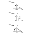
- FIG. 3 is a graph showing the frequency spectra of the reception signals 31 and 32 and the frequency characteristic of the ultrasonic sensor 2 in the first embodiment, and FIG. 3A shows that the obstacle is stationary relative to the host vehicle.
- FIG. 3B is an example in which an obstacle is relatively close to the vehicle
- FIG. 3C is an example in which the obstacle is relatively away from the vehicle.
- the horizontal axis of each graph is the frequency
- the vertical axis is the reception intensity of the received signal.
- the probe wave 21 having the frequency f1 and the probe wave 22 having the frequency f2 shown in FIG. 2 are transmitted from the ultrasonic sensor 2.
- the frequency characteristic itself of the ultrasonic sensor 2 operates as a bandpass filter. Therefore, as shown in FIG. 3A, the reflected wave reflected by the obstacle relatively stationary with respect to the own vehicle, that is, the obstacle having the relative velocity of zero does not cause the Doppler shift, and therefore, the search wave 21
- the reception intensity of the corresponding reception signal 31 and the reception intensity of the reception signal 32 corresponding to the search wave 22 are substantially the same.
- the frequency of the reflected wave reflected by this obstacle shifts to the high frequency side by the frequency shift amount fd due to Doppler shift. Therefore, the passing loss of the reflected wave ultrasonic sensor 2 having the frequency f1 + fd is smaller than the passing loss of the reflected wave ultrasonic sensor 2 having the frequency f2 + fd. Therefore, as shown in FIG. 3B, the reception intensity of the reception signal 31 corresponding to the exploration wave 21 is higher than the reception intensity of the reception signal 32 corresponding to the exploration wave 22.
- the frequency of the reflected wave reflected by this obstacle shifts to the low frequency side by the frequency shift amount fd due to Doppler shift. Therefore, the passing loss of the reflected wave ultrasonic sensor 2 having the frequency f2 + fd is smaller than the passing loss of the reflected wave ultrasonic sensor 2 having the frequency f1 + fd. Therefore, as shown in FIG. 3C, the reception intensity of the reception signal 32 corresponding to the search wave 22 is larger than the reception intensity of the reception signal 31 corresponding to the search wave 21.
- the Doppler shift of the reflected wave can be detected as a change in the reception intensity of the reception signal by using the frequency characteristics of the ultrasonic sensor 2 itself.
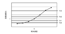
- FIG. 4 is a graph illustrating the determination process performed by the dynamic state determination unit 15 according to the first embodiment.
- the horizontal axis of the graph is the relative speed of the vehicle and the obstacle, and the vertical axis is the reception intensity ratio P.
- the reception intensity ratio P is a ratio of the reception intensity of the reception signal 31 to the reception intensity of the reception signal 32, that is, (reception intensity of the reception signal 31) / (reception intensity of the reception signal 32).
- the movement determination unit 15 compares the two thresholds Th1 and Th2 with the reception intensity ratio P to determine whether the obstacle is relatively stationary, approaching, or moving away from the own vehicle. Specifically, in the example of FIG. 4, the dynamic determination unit 15 determines that the obstacle is relatively stationary with respect to the own vehicle when Th1 ⁇ P ⁇ Th2. Further, the movement determination unit 15 determines that the obstacle is relatively close to the own vehicle when Th2 ⁇ P. Further, the movement determination unit 15 determines that the obstacle is relatively distant from the own vehicle when Th1 ⁇ P.
- the dynamic determination unit 15 uses the thresholds Th3 and Th4 in addition to the thresholds Th1 and Th2 to determine whether an approaching obstacle is slowly approaching or approaching rapidly, and whether an obstacle that is moving away slowly separates from each other. It may be determined whether or not. Specifically, in the example of FIG. 4, the dynamic determination unit 15 determines that the obstacle is relatively close to the own vehicle when Th3 ⁇ P, and Th2 ⁇ P ⁇ Th3. In some cases, it is determined that they are approaching slowly. In addition, the dynamic determination unit 15 determines that the obstacle is relatively suddenly separated from the own vehicle when Th4 ⁇ P, and is slowly separated when Th4 ⁇ P ⁇ Th1. judge.
- FIG. 5 is a flowchart showing an operation example of the obstacle detection device 1 according to the first embodiment.
- the obstacle detection device 1 repeats the operation shown in the flowchart of FIG.
- the search wave transmitter 12 causes the ultrasonic sensor 2 to transmit the search waves 21 and 22 having the frequencies f1 and f2 at the transmission timing instructed by the search wave controller 11 (step ST1).
- the reflected wave receiving unit 13 converts the reflected wave into a received signal and outputs the received signal to the reflected wave analysis unit 14.
- the reflected wave analysis unit 14 calculates the reception intensities of the reception signals 31 and 32 corresponding to the exploration waves 21 and 22, and also calculates the distance to the obstacle using the reception signals 31 and 32 (step ST3).
- the same object determination unit 16 uses the distance to the obstacle to determine whether the received signals 31 and 32 are reflected by the same obstacle (step ST4).
- the movement determination unit 15 compares the reception intensity ratio of the reception signals 31 and 32 with two or more threshold values. By doing so, it is determined whether the obstacle is relatively stationary, approaching, or moving away from the own vehicle (step ST5).
- the ultrasonic sensor 2 does not receive the reflected wave (step ST2 “NO”), or when the received signals 31 and 32 are not reflected by the same obstacle (step ST4 “NO”). The process returns to step ST1.
- the obstacle detection device 1 includes the exploration wave transmission unit 12, the exploration wave control unit 11, the reflected wave reception unit 13, the reflected wave analysis unit 14, and the movement determination unit 15.
- the search wave transmitter 12 causes the ultrasonic sensor 2 to send search waves 21 and 22 having two different frequencies f1 and f2 that straddle the resonance frequency f0 of the ultrasonic sensor 2 provided in the vehicle.
- the search wave control unit 11 controls the frequencies f1 and f2 of the search waves 21 and 22 transmitted by the search wave transmission unit 12 from the ultrasonic sensor 2.
- the reflected wave receiving unit 13 converts the reflected waves received by the ultrasonic sensor 2 when the search waves 21 and 22 are reflected by an obstacle into received signals.
- the reflected wave analysis unit 14 calculates the respective reception intensities of the reception signals 31 and 32 corresponding to the search waves 21 and 22.
- the movement determination unit 15 determines whether the obstacle is relatively stationary, approaching, or moving away from the vehicle based on the ratio of the reception intensities calculated by the reflected wave analysis unit 14.
- the obstacle detection device 1 has a simple configuration without performing frequency analysis as in the related art, and whether the obstacle is relatively stationary, approaching, or moving away from the own vehicle. Can be determined. Further, the obstacle detection device 1 can determine the relative speed of the obstacle with a smaller number of times of exploration, rather than determining the relative speed of the obstacle by repeating transmission and reception of exploration waves. It is possible to lengthen the distance margin when automatically controlling the vehicle.
- the frequency f1 of the search wave 21 and the frequency f2 of the search wave 22 are line-symmetric with respect to the resonance frequency f0 of the ultrasonic sensor 2.
- the movement determination unit 15 can determine both the relative speed on the plus side and the relative speed on the minus side, and thus can determine both the approach and the departure.
- the exploration wave transmitting unit 12 of the first embodiment may combine the exploration waves 21 and 22 having two different frequencies f1 and f2 and cause the ultrasonic sensor 2 to transmit them at the same time.
- the movement of the obstacle can be determined in a shorter time than in the case of the time division transmission method.
- Embodiment 2 The first embodiment has described the example in which the frequency f1 and the frequency f2 are line-symmetric with respect to the resonance frequency f0 of the ultrasonic sensor 2. In the second embodiment, an example in which the frequency f1 and the frequency f2 are non-axisymmetric with respect to the resonance frequency f0 of the ultrasonic sensor 2 will be described.
- FIG. 6 is a block diagram showing a configuration example of the obstacle detection device 1 according to the second embodiment.
- the obstacle detection device 1 according to the second embodiment is replaced with the search wave control unit 11, the search wave transmission unit 12, and the movement determination unit 15 in the obstacle detection device 1 of the first embodiment shown in FIG. ,
- the exploration wave control unit 11a, the exploration wave transmission unit 12a, and the movement determination unit 15a. 6 that are the same as or correspond to those in FIG. 1 are assigned the same reference numerals and explanations thereof are omitted.
- the exploration wave control unit 11a can determine the approach speed between the own vehicle and the obstacle to a higher speed range.
- the frequencies f1 and f2 are set and instructed to the exploration wave transmitting unit 12a.
- the exploration wave control unit 11a shifts the two frequencies f1 and f2 straddling the resonance frequency f0 to a lower frequency side than the frequencies f1 and f2 shown in FIG. 2 and sets them to the values shown in FIG. 7A. To do.
- the exploration wave control unit 11a may set the frequency f1 to be lower than the resonance frequency f0 of the ultrasonic sensor 2 and set the frequency f2 to the resonance frequency f0 of the ultrasonic sensor 2 as shown in FIG. 7B. ..
- the frequencies f1 and f2 are set as shown in FIGS. 7A and 7B, the frequencies f2 + fd and f2 + fd of the reflected waves are increased even if the approaching speed between the own vehicle and the obstacle is increased and the frequency shift amount fd due to the Doppler effect is increased.
- the ultrasonic sensor 2 Within the reception frequency band of the ultrasonic sensor 2, it is possible for the ultrasonic sensor 2 to receive.
- the exploration wave control unit 11a can determine the separation speed between the own vehicle and the obstacle to a higher speed range.
- the frequencies f1 and f2 are set and instructed to the exploration wave transmitting unit 12a.
- the exploration wave control unit 11a shifts the two frequencies f1 and f2 across the resonance frequency f0 to a higher frequency side than the frequencies f1 and f2 shown in FIG. 2 and sets them to the values shown in FIG. 8A. To do.
- the exploration wave control unit 11a may set the frequency f1 to the resonance frequency f0 of the ultrasonic sensor 2 and set the frequency f2 higher than the resonance frequency f0 of the ultrasonic sensor 2 as shown in FIG. 8B. ..
- the frequencies f1 and f2 are set as shown in FIG. 8A and FIG. 8B, the frequency f1-fd of the reflected wave is increased even if the separation speed between the vehicle and the obstacle is increased and the frequency shift amount fd due to the Doppler effect is increased.
- F2-fd are within the reception frequency band of the ultrasonic sensor 2, so that the ultrasonic sensor 2 can receive.
- the transmission intensity of the search wave 21 and the transmission intensity of the search wave 22 are the same. Therefore, as shown in FIG. 3, the reception intensity ratio between the reception signal 31 and the reception signal 32 becomes “1” when the obstacle is relatively stationary with respect to the own vehicle.
- FIGS. 7A, 7B, 8A, and 8B when the frequencies f1 and f2 are axisymmetric with respect to the resonance frequency f0, the transmission intensity of the search wave 21 and the search wave 22 The transmission strength is different. Therefore, the reception intensity ratio of the reception signal 31 and the reception signal 32 does not become "1" when the obstacle is relatively stationary with respect to the own vehicle. Therefore, by comparing the reception intensity ratio with the threshold values Th1 to Th4, it is not possible to correctly determine whether the obstacle is relatively stationary, approaching, or moving away from the own vehicle.
- the exploration wave control unit 11a instructs the exploration wave transmission unit 12a to make the transmission intensities of the exploration waves 21 and 22 the same.
- the exploration wave transmission unit 12a transmits the exploration wave 21 or the exploration wave 22 so that the transmission intensity of the exploration wave 21 transmitted from the ultrasonic sensor 2 is equal to the transmission intensity of the exploration wave 22.
- At least one of the transmission intensities is corrected. For example, when the ratio between the transmission intensity of the exploration wave 21 and the transmission intensity of the exploration wave 22 is “1: 2” as shown in FIG. 7B, the exploration wave control unit 11 a doubles the transmission intensity of the exploration wave 21.
- the exploration wave transmission unit 12a is instructed to make a correction.
- the exploration wave control unit 11a instructs the dynamic state determination unit 15a to correct at least one of the reception intensity of the reception signal 31 and the reception intensity of the reception signal 32 according to the transmission intensity ratio of the exploration waves 21 and 22.
- the dynamic determination unit 15a corrects at least one of the reception intensity of the reception signal 31 and the reception intensity of the reception signal 32. For example, when the ratio between the transmission intensity of the exploration wave 21 and the transmission intensity of the exploration wave 22 is “1: 2” as shown in FIG. 7B, the exploration wave control unit 11a doubles the reception intensity of the reception signal 31.
- the dynamic determination unit 15a is instructed to make the correction.
- the frequency characteristic of the ultrasonic sensor 2 is the resonance frequency f0 due to the characteristics of the circuit that drives the ultrasonic sensor 2 (for example, the transmission / reception analog circuit 101 of FIG. 14 described later) or the Q value of the ultrasonic sensor 2.
- the frequencies f1 and f2 are axisymmetric with respect to the resonance frequency f0, the transmission intensity of the search wave 21 and the transmission intensity of the search wave 22 are different.
- the exploration wave transmitting unit 12a may correct at least one of the transmission intensity of the exploration wave 21 and the transmission intensity of the exploration wave 22.
- the dynamic determination unit 15a may correct at least one of the reception intensity of the reception signal 31 and the reception intensity of the reception signal 32.
- the exploration wave transmitting unit 12a according to the second embodiment has two different frequencies f1 and f2 including the same frequency f2 as the resonance frequency f0 of the ultrasonic sensor 2 provided in the vehicle, as shown in FIG. 7B.
- the search waves 21 and 22 are transmitted from the ultrasonic sensor 2.
- the obstacle detection device 1 can determine the approach speed between the vehicle and the obstacle up to a higher speed range.
- the exploration wave transmitting unit 12a according to the second embodiment includes the exploration waves 21 having two different frequencies f1 and f2 including the same frequency f1 as the resonance frequency f0 of the ultrasonic sensor 2 provided in the vehicle.
- 22 may be transmitted from the ultrasonic sensor 2.
- the obstacle detection device 1 can determine the separation speed between the vehicle and the obstacle up to a higher speed range.
- the obstacle detection device 1 can determine the approach speed between the vehicle and the obstacle up to a higher speed range.
- the obstacle detection device 1 can determine the separation speed between the vehicle and the obstacle up to a higher speed range.
- the exploration wave transmitting unit 12a corrects the transmission intensity of the exploration waves 21 and 22, or the dynamic determination unit 15a corrects the reception intensity of the reception signals 31 and 32.
- the obstacle detection device 1 detects an obstacle even when the frequency f1 of the search wave 21 and the frequency f2 of the search wave 22 are axisymmetric with respect to the resonance frequency f0 of the ultrasonic sensor 2. It is possible to accurately determine whether the vehicle is relatively stationary, approaching, or moving away from the vehicle.
- the exploration wave transmitting unit 12a corrects the transmission intensity of the exploration waves 21 and 22, or the dynamic determination unit 15a corrects the reception intensity of the reception signals 31 and 32.
- the determination unit 15a may be configured to correct the threshold values Th1 to Th4 based on the transmission intensity ratio between the exploration waves 21 and 22.
- Embodiment 3 In the first and second embodiments, the example has been described using one ultrasonic sensor 2. In the third embodiment, the dynamics of the obstacle are determined using the direct wave and the indirect wave received by linking the plurality of ultrasonic sensors 2.
- the direct wave is a wave in a propagation path that is an ultrasonic sensor that transmits an exploration wave and that receives the reflected wave that is reflected by an obstacle.
- An indirect wave is a different ultrasonic sensor other than the ultrasonic sensor that transmitted the exploration wave, and is a wave on the propagation path that receives the reflected wave that the exploration wave reflects from an obstacle.
- FIG. 9 is a block diagram showing a configuration example of the obstacle detection device 1 according to the third embodiment.
- the obstacle detection device 1 according to the third embodiment has a configuration including a movement determination unit 15b instead of the movement determination unit 15 in the obstacle detection device 1 according to the first embodiment shown in FIG.
- the ultrasonic sensor 2 is composed of N ultrasonic sensors 2-1 to 2-N (N is an arbitrary integer of 2 or more). 9 that are the same as or correspond to those in FIG. 1 are assigned the same reference numerals and explanations thereof are omitted.
- FIG. 10 shows an example of mounting the ultrasonic sensors 2-1 to 2-12 in the vehicle in the third embodiment.
- FIG. 10A is a side view and FIG. 10B is a plan view.
- six ultrasonic sensors 2-1 to 2-6 are attached to the front side of the vehicle, and six ultrasonic sensors 2-7 to 2-12 are attached to the rear side of the vehicle.
- all of the ultrasonic sensors 2-1 to 2-12 are mounted at the same height, but they may be mounted at different heights.
- the ultrasonic sensor 2-1 is used as a “first ultrasonic sensor” and the ultrasonic sensor 2-2 is used as a “second ultrasonic sensor” will be described.
- the combination of the ultrasonic sensors used as the first ultrasonic sensor and the second ultrasonic sensor may be arbitrary.
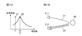
- FIG. 11A is a graph showing the frequency spectrum of the search waves 21 and 22 and the frequency characteristics of the ultrasonic sensors 2-1 and 2-2 in the third embodiment.
- the horizontal axis of the graph is the frequency of the exploration wave
- the vertical axis is the transmission intensity of the exploration wave.
- the transmission intensity of the search wave 21 having the frequency f1 and the transmission intensity of the search wave 22 having the frequency f2 are the same. It is assumed that it has been corrected by the exploration wave transmission unit 12.
- FIG. 11B is a diagram for explaining the propagation paths of the exploration waves 21 and 22 in the third embodiment.
- the search wave transmitter 12 causes the ultrasonic sensor 2-1 to send the search wave 21 having the frequency f1. Further, the search wave transmitter 12 causes the ultrasonic sensor 2-2 to send the search wave 22 having the frequency f2.
- the exploration wave 21 is reflected by the obstacle 40 and is received by the ultrasonic sensor 2-2 as an indirect wave.
- the exploration wave 22 is reflected by the obstacle 40 and is received as a direct wave by the ultrasonic sensor 2-2.
- the reflected wave analysis unit 14 uses the received signal 31 of the indirect wave corresponding to the exploration wave 21 to calculate the reception intensity and the distance to the obstacle 40. Further, the reflected wave analysis unit 14 uses the received signal 32 of the direct wave corresponding to the exploration wave 22 to calculate the reception intensity and the distance to the obstacle 40.
- the same object determination unit 16 calculates an ellipse using the distance calculated from the received signal 31 with each vehicle mounting position of the ultrasonic sensor 2-1 and the ultrasonic sensor 2-2 as a focus. The same object determination unit 16 also calculates a circle centered on the vehicle mounting position of the ultrasonic sensor 2-2 and having a radius calculated from the received signal 32. Then, the same object determination unit 16 calculates the intersection of the ellipse and the circle, and sets the position of the calculated intersection as the position of the obstacle 40.
- the dynamic state determination unit 15b sets the ratio of the reception intensity of the reception signal 31 of the indirect wave corresponding to the exploration wave 21 to the reception intensity of the reception signal 32 of the direct wave corresponding to the exploration wave 22 to a predetermined ratio of 2 or more.
- the dynamics of the obstacle 40 are determined by comparing the dynamics of the obstacle 40.
- FIG. 12 is a graph for explaining the received signals 31, 32 when the obstacle 40 is stationary relative to the own vehicle in the third embodiment.
- FIG. 12A shows the frequency spectra of the reception signals 31 and 32 and the ultrasonic sensors 2-1 and 2- when the search waves 21 and 22 shown in FIG. 11 are transmitted from the ultrasonic sensors 2-1 and 2-2. It is a graph which shows the frequency characteristic of No. 2.
- the horizontal axis of the graph is frequency and the vertical axis is reception intensity.
- FIG. 12B is a graph showing the waveforms of the reception signals 31 and 32 when the search waves 21 and 22 shown in FIG. 11 are transmitted from the ultrasonic sensors 2-1 and 2-2.
- the horizontal axis of the graph is the propagation time and the vertical axis is the reception intensity.
- FIG. 13 is a graph for explaining the received signals 31 and 32 when the obstacle 40 is relatively close to the own vehicle in the third embodiment.
- FIG. 13A shows the frequency spectra of the reception signals 31 and 32 and the ultrasonic sensors 2-1 and 2- when the search waves 21 and 22 shown in FIG. 11 are transmitted from the ultrasonic sensors 2-1 and 2-2. It is a graph which shows the frequency characteristic of No. 2.
- the horizontal axis of the graph is frequency and the vertical axis is reception intensity.
- FIG. 13B is a graph showing the waveforms of the reception signals 31 and 32 when the search waves 21 and 22 shown in FIG. 11 are transmitted from the ultrasonic sensors 2-1 and 2-2.
- the horizontal axis of the graph is the propagation time and the vertical axis is the reception intensity.
- the propagation distance of the exploration wave 21 which is an indirect wave is longer than the propagation distance of the exploration wave 22 which is a direct wave. Therefore, as shown in FIGS. 12B and 13B, the propagation time of the reception signal 31 which is an indirect wave is longer than the propagation time of the reception signal 32 which is a direct wave.
- the probe wave transmitted by the ultrasonic sensor 2 has a larger attenuation as the propagation distance is longer. Therefore, even if the probe waves 21 and 22 have the same transmission intensity, the reception intensity of the reception signal 31, which is an indirect wave, is direct. It becomes smaller than the reception intensity of the reception signal 32 which is a wave.
- the reception intensity ratio of the reception signal 31 and the reception signal 32 when the obstacle 40 is relatively stationary with respect to the vehicle. Does not become “1". Therefore, by comparing the reception intensity ratio with the threshold values Th1 to Th4, it is not possible to correctly determine whether the obstacle 40 is stationary, approaching, or moving away from the own vehicle.
- the dynamic state determination unit 15b uses spatial propagation when calculating the ratio of the reception intensity of the reception signal 31 that is the indirect wave and the reception intensity of the reception signal 32 that is the direct wave calculated by the reflected wave analysis unit 14. Correct the attenuation. For example, a correction coefficient for each propagation time for correcting the attenuation due to spatial propagation is given to the dynamic determination unit 15b in advance.
- the dynamic determination unit 15b corrects the reception intensity of the received signal 31 using the correction coefficient corresponding to the propagation time of the received signal 31, and uses the correction coefficient corresponding to the propagation time of the received signal 32 to receive the received signal 32. Correct the reception strength of. Thereby, the movement determination unit 15b can correctly determine the movement of the obstacle 40 by using the reception intensity ratio of the direct wave and the indirect wave.
- the search wave transmission unit 12 of the third embodiment causes the search wave 21 having the frequency f1 to be transmitted from the ultrasonic sensor 2-1 that is the first ultrasonic sensor. Further, the search wave transmission unit 12 causes the search wave 22 having the frequency f2 to be transmitted from the ultrasonic sensor 2-2 which is the second ultrasonic sensor.
- the reflected wave receiving unit 13 transmits an indirect wave received by the ultrasonic sensor 2-2 after the exploration wave 21 transmitted from the ultrasonic sensor 2-1 is reflected by the obstacle 40 and transmitted from the ultrasonic sensor 2-2.
- the detected exploration wave 22 is reflected by the obstacle 40, and the direct wave received by the ultrasonic sensor 2-2 is converted into a reception signal.
- the reflected wave analysis unit 14 calculates the reception intensity of each of the received signal 31 of the indirect wave and the received signal 32 of the direct wave.
- the dynamic state determination unit 15b corrects the attenuation due to spatial propagation when calculating the reception intensity ratio between the reception signal 31 of the indirect wave and the reception signal 32 of the direct wave calculated by the reflected wave analysis unit 14. With this configuration, the obstacle detection device 1 can accurately calculate the reception intensity ratio when using the direct wave and the indirect wave.
- the dynamic determination unit 15b is configured to correct the reception intensity of the received signals 31 and 32, but the dynamic determination unit 15b determines the threshold values Th1 to Th4 based on the propagation time of the received signals 31 and 32. May be corrected.
- the transmission unit 12 may correct the transmission intensity of the exploration waves 21 and 22, or the movement determination unit 15b may correct the reception intensity of the reception signals 31 and 32.
- the exploration wave transmission unit 12 modulates the exploration wave 21 and the exploration wave 22 with different codes to cause mutual interference. May be suppressed.
- the structure of the obstacle detection device 1 according to the fourth embodiment is the same as the structure shown in FIG. 1, FIG. 6 or FIG. 9 of the first to third embodiments, FIG. To do.
- a change in the resonance frequency f0 of the ultrasonic sensor 2 due to a change in ambient temperature is corrected to determine the movement of the obstacle with higher accuracy.
- the exploration wave control unit 11 acquires the ambient temperature from the temperature sensor.
- the temperature sensor is mounted in, for example, a circuit that drives the ultrasonic sensor 2 (for example, a transmission / reception analog circuit 101 in FIG. 14 described later).
- the exploration wave control unit 11 determines the frequencies f1 and f2 corresponding to the ambient temperature measured by the temperature sensor using the temperature correction table created in advance, and instructs the exploration wave transmission unit 12 to do so. Specifically, the exploration wave control unit 11 shifts the frequencies f1 and f2 to the low frequency side when the ambient temperature is high compared to when the ambient temperature is low.
- the exploration wave transmitter 12 causes the ultrasonic sensor 2 to transmit the exploration waves 21 and 22 having the frequencies f1 and f2 instructed by the exploration wave controller 11.
- the exploration wave control unit 11 of the fourth embodiment shifts the frequencies f1 and f2 to the low frequency side when the ambient temperature is high compared to when the ambient temperature is low.
- the obstacle detection device 1 can determine the movement of the obstacle with higher accuracy.
- FIG. 14 is a hardware configuration diagram of the obstacle detection device 1 according to each embodiment.
- the exploration wave control unit 11, the reflected wave analysis unit 14, the movement determination unit 15, and the same object determination unit 16 in the obstacle detection device 1 are the digital signal processing circuit 104.
- the exploration wave transmitter 12 includes a transmission / reception analog circuit 101 and a DAC (Digital to Analog Converter) 102.
- the reflected wave receiving unit 13 includes a transmission / reception analog circuit 101 and an ADC (Analog to Digital Converter) 103.
- ADC Analog to Digital Converter
- the digital signal processing circuit 104 generates search signals of frequencies f1 and f2 and outputs them to the transmission / reception analog circuit 101 via the DAC 102.
- the transmission / reception analog circuit 101 amplifies the search signal up to a predetermined power and outputs it to the ultrasonic sensor 2. Further, the transmission / reception analog circuit 101 amplifies the reflected wave received by the ultrasonic sensor 2 to remove noise.
- the ADC 103 converts the reflected wave that has been amplified and noise-removed by the transmission / reception analog circuit 101 into a reception signal.
- the digital signal processing circuit 104 calculates the reception intensity and the distance to the obstacle using the reception signal, and determines the dynamics of the obstacle by thresholding the reception intensity ratio.
- a communication IF (Interface) 105 transmits information on the distance to the obstacle and the movement to other in-vehicle devices mounted on the vehicle.
- the in-vehicle device is, for example, a collision avoidance device, a vehicle side object detection device, a corner sensor, an automatic parking device, or a vehicle control device.
- the transmitting / receiving analog circuit 101 is, for example, a single circuit, a composite circuit, a programmed processor, a parallel programmed processor, an ASIC (Application Specific Integrated Circuit), an FPGA (Field Programmable Gate Array), or a combination thereof. Is applicable.
- the digital signal processing circuit 104 includes a memory and a processor that executes a program stored in the memory.
- the functions of the exploration wave control unit 11, the reflected wave analysis unit 14, the movement determination unit 15, and the same object determination unit 16 are realized by software, firmware, or a combination of software and firmware.
- Software or firmware is described as a program and stored in the memory.
- the processor realizes the function of each unit by reading and executing the program stored in the memory. That is, the digital signal processing circuit 104 includes a memory for storing a program that, when executed by the processor, will result in the steps shown in the flowchart of FIG. 5 being executed. It can also be said that this program causes a computer to execute the procedure or method of the exploration wave control unit 11, the reflected wave analysis unit 14, the movement determination unit 15, and the same object determination unit 16.
- the obstacle detection device according to the present invention can be applied to, for example, surrounding monitoring, collision avoidance, or parking assistance control.
- 1 Obstacle detection device 2, 2-1 to 2-12, 2-N ultrasonic sensor, 11, 11a exploration wave control unit, 12, 12a exploration wave transmission unit, 13 reflected wave reception unit, 14 reflected wave analysis unit , 15, 15a, 15b Dynamic determination unit, 16 Identical object determination unit, 21, 22 Search wave, 31, 32 Received signal, 40 Obstacle, 101 Transmit / receive analog circuit, 102 DAC, 103 ADC, 104 Digital signal processing circuit, 105 Communication IF, f0 resonance frequency, f1, f2 frequency, Th1 to Th4 threshold.
Landscapes
- Physics & Mathematics (AREA)
- Engineering & Computer Science (AREA)
- Radar, Positioning & Navigation (AREA)
- Remote Sensing (AREA)
- Acoustics & Sound (AREA)
- Computer Networks & Wireless Communication (AREA)
- General Physics & Mathematics (AREA)
- Measurement Of Velocity Or Position Using Acoustic Or Ultrasonic Waves (AREA)
Abstract
探査波送信部(12)は、超音波センサ(2)の共振周波数(f0)をまたぐ2つの異なる周波数(f1,f2)の探査波(21,22)を、超音波センサ(2)から送信させる。反射波解析部(14)は、2つの異なる周波数(f1,f2))の探査波(21,22)に対応する2つの受信信号(31,32)の各受信強度を算出する。動態判定部(15)は、受信強度比に基づいて、障害物が車両に対して相対的に静止、接近、又は離反のいずれであるかを判定する。
Description
この発明は、車両周辺の障害物を検知する障害物検知装置に関するものである。
特許文献1に係る歩行支援装置は、周波数の異なる2つの信号を送信し、その反射信号から得られた2つのドップラ信号の位相差を用いて、障害物までの距離を検出する。また、上記歩行支援装置は、上記2つのドップラ信号のいずれかを用いて、ドップラ周波数から障害物の相対速度を検出する。
従来の障害物検知装置は以上のように構成されているので、ドップラ周波数を解析する機能が必要となり、演算負荷が大きくなる、及び装置コストが高くなるという課題があった。
この発明は、上記のような課題を解決するためになされたもので、周波数解析を実施することなく、簡易な構成で、障害物が自車に対して相対的に静止、接近、又は離反のいずれであるかを判定することを目的とする。
この発明に係る障害物検知装置は、車両に設けられた超音波センサの共振周波数をまたぐ2つの異なる周波数の探査波、又は共振周波数と同じ周波数を含む2つの異なる周波数の探査波を、超音波センサから送信させる探査波送信部と、探査波送信部が超音波センサから送信させる探査波の2つの異なる周波数を制御する探査波制御部と、探査波が障害物で反射して超音波センサにより受信された反射波を受信信号に変換する反射波受信部と、2つの異なる周波数の探査波に対応する2つの受信信号の各受信強度を算出する反射波解析部と、反射波解析部により算出された受信強度の比に基づいて、障害物が車両に対して相対的に静止、接近、又は離反のいずれであるかを判定する動態判定部とを備えるものである。
この発明によれば、周波数解析を実施することなく、簡易な構成で、障害物が自車に対して相対的に静止、接近、又は離反のいずれであるかを判定することができる。
以下、この発明をより詳細に説明するために、この発明を実施するための形態について、添付の図面に従って説明する。
実施の形態1.
図1は、実施の形態1に係る障害物検知装置1の構成例を示すブロック図である。車両には、障害物検知装置1、及び1個以上の超音波センサ2が搭載されている。障害物検知装置1には、超音波センサ2が接続されている。
実施の形態1.
図1は、実施の形態1に係る障害物検知装置1の構成例を示すブロック図である。車両には、障害物検知装置1、及び1個以上の超音波センサ2が搭載されている。障害物検知装置1には、超音波センサ2が接続されている。
障害物検知装置1は、探査波制御部11、探査波送信部12、反射波受信部13、反射波解析部14、及び動態判定部15を備える。動態判定部15は、同一物体判定部16を有する。
探査波制御部11は、探査波の送信タイミング及び送信方法を、探査波送信部12へ指示する。また、探査波制御部11は、探査波の周波数を制御する。
探査波送信部12は、探査波制御部11から指示された送信タイミング及び送信方法に従って、探査波制御部11により制御される周波数の探査信号を生成し、超音波センサ2へ出力する。
超音波センサ2は、探査波送信部12からの探査信号を、探査波として空間へ送信する。超音波センサ2が送信した探査波は、車両周辺の障害物で反射し、反射波として超音波センサ2により受信される。
図2は、実施の形態1における探査波21,22の周波数スペクトルと超音波センサ2の周波数特性とを示すグラフである。グラフの横軸は探査波の周波数、縦軸は探査波の送信強度である。図2の例では、探査波送信部12が、超音波センサ2の共振周波数f0より低い周波数f1をもつ探査波21と、共振周波数f0より高い周波数f2をもつ探査波22とを生成する。図2に示されるように、超音波センサ2から送信される探査波21の周波数f1と探査波22の周波数f2とは、超音波センサ2の共振周波数f0に対して線対称である。また、図2に曲線で示された超音波センサ2の周波数特性は、共振周波数f0に対して線対称である。そのため、探査波21と探査波22とは、同じ強度で空間へ送信される。
ここで、探査波の送信方法について説明する。
送信方法は、時分割送信方法、周波数多重送信方法、又は変調信号送信方法がある。探査波制御部11は、これらの送信方法のうちの1つを選択して探査波送信部12に指示する。時分割送信方法は、探査波21と探査波22とを切り替えながら超音波センサ2から送信するものである。周波数多重送信方法は、探査波21と探査波22とを合成して超音波センサ2から同時に送信するものである。変調信号送信方法は、チャープ変調若しくはFSK(Frequency Shift Keying)変調等の周波数変調、又はPSK(Phase Shift Keying)変調等の位相変調により広帯域化した信号を探査波として超音波センサ2から送信するものである。
送信方法は、時分割送信方法、周波数多重送信方法、又は変調信号送信方法がある。探査波制御部11は、これらの送信方法のうちの1つを選択して探査波送信部12に指示する。時分割送信方法は、探査波21と探査波22とを切り替えながら超音波センサ2から送信するものである。周波数多重送信方法は、探査波21と探査波22とを合成して超音波センサ2から同時に送信するものである。変調信号送信方法は、チャープ変調若しくはFSK(Frequency Shift Keying)変調等の周波数変調、又はPSK(Phase Shift Keying)変調等の位相変調により広帯域化した信号を探査波として超音波センサ2から送信するものである。
反射波受信部13は、超音波センサ2により受信された反射波を受信信号に変換し、変換した受信信号を反射波解析部14へ出力する。
反射波解析部14は、反射波受信部13からの受信信号のうち、周波数f1をもつ探査波21に対応する受信信号成分(以下、「受信信号31」と称する)の受信強度と、周波数f2をもつ探査波22に対応する受信信号成分(以下、「受信信号32」と称する)の受信強度とを算出する。
探査波の送信方法が時分割送信方法である場合、反射波解析部14は、超音波センサ2が探査波21を送信したときの受信信号を受信信号31とみなしてその受信強度を算出し、超音波センサ2が探査波22を送信したときの受信信号を受信信号32とみなしてその受信強度を算出する。
探査波の送信方法が周波数多重送信方法又は変調信号送信方法である場合、反射波解析部14は、共振周波数f0より低い周波数帯域が通過するフィルタを用いて、受信信号から受信信号31を分離する。また、反射波解析部14は、共振周波数f0より高い周波数帯域が通過するフィルタを用いて、受信信号から受信信号32を分離する。そして、反射波解析部14は、分離後の受信信号31の受信強度と、分離後の受信信号32の受信強度を算出する。
なお、共振周波数f0より低い周波数帯域が通過するフィルタは、周波数f1が通過するのはもちろんのこと、周波数f1が高周波数側又は低周波数側にドップラシフトした周波数も通過するように設計される。同様に、共振周波数f0より高い周波数帯域が通過するフィルタは、周波数f2が通過するのはもちろんのこと、周波数f2が高周波数側又は低周波数側にドップラシフトした周波数も通過するように設計される。
なお、共振周波数f0より低い周波数帯域が通過するフィルタは、周波数f1が通過するのはもちろんのこと、周波数f1が高周波数側又は低周波数側にドップラシフトした周波数も通過するように設計される。同様に、共振周波数f0より高い周波数帯域が通過するフィルタは、周波数f2が通過するのはもちろんのこと、周波数f2が高周波数側又は低周波数側にドップラシフトした周波数も通過するように設計される。
また、反射波解析部14は、受信信号31を用いて、超音波センサ2が探査波を送信してから反射波を受信するまでの伝搬遅延時間ΔTを算出する。そして、反射波解析部14は、探査波の伝搬速度Vと伝搬遅延時間ΔTとを用いて、式(1)を計算し、超音波センサ2から障害物までの距離Lを求める。同様に、反射波解析部14は、受信信号32を用いて式(1)を計算し、障害物までの距離Lを求める。そして、反射波解析部14は、受信信号31の受信強度、受信信号32の受信強度、及び障害物までの距離を、動態判定部15へ出力する。
L=(V×ΔT)/2 (1)
L=(V×ΔT)/2 (1)
同一物体判定部16は、受信信号31と受信信号32とが同一の障害物で反射したものであるか否かを判定する。
探査波の送信方法が時分割送信方法である場合、同一物体判定部16は、反射波解析部14が受信信号31を用いて算出した障害物までの距離と、受信信号31を受信した時点から受信信号32を受信した時点までの自車の移動距離とを用いて、受信信号32を受信した時点で障害物が存在するであろう距離範囲を予測する。そして、同一物体判定部16は、反射波解析部14が受信信号32を用いて算出した障害物までの距離が、予測した距離範囲内にある場合、受信信号31と受信信号32とが同一の障害物で反射したものであると判定する。
探査波の送信方法が周波数多重送信方法又は変調信号送信方法である場合、同一物体判定部16は、反射波解析部14が受信信号31を用いて算出した障害物までの距離と、反射波解析部14が受信信号32を用いて算出した障害物までの距離とを比較する、そして、同一物体判定部16は、両者が同一である場合、受信信号31と受信信号32とが同一の障害物で反射したものであると判定する。
動態判定部15は、同一物体判定部16により同一の障害物で反射したと判定された受信信号31と受信信号32との受信強度比を算出する。そして、動態判定部15は、受信強度比と、予め定められた2つ以上の閾値とを比較することにより、障害物の動態、すなわち障害物が自車に対して相対的に静止、接近、又は離反のいずれであるかを判定する。
図3は、実施の形態1における受信信号31,32の周波数スペクトルと超音波センサ2の周波数特性とを示すグラフであり、図3Aは障害物が自車に対して相対的に静止している例、図3Bは障害物が自車に対して相対的に接近している例、図3Cは障害物が自車に対して相対的に離反している例である。各グラフの横軸は周波数、縦軸は受信信号の受信強度である。ここでは、図2に示される周波数f1をもつ探査波21と、周波数f2をもつ探査波22とが超音波センサ2から送信されたものとする。
超音波センサ2が反射波を受信する際に、超音波センサ2の周波数特性自身がバンドパスフィルタとして動作する。そのため、図3Aのように、自車に対して相対的に静止している障害物、すなわち相対速度がゼロの障害物で反射した反射波は、ドップラシフトが生じていないので、探査波21に対応する受信信号31の受信強度と、探査波22に対応する受信信号32の受信強度とは、ほぼ同一となる。
障害物が自車に対して相対的に接近している場合、この障害物で反射した反射波の周波数は、ドップラシフトにより周波数シフト量fdだけ高周波数側へシフトする。このため、周波数f1+fdをもつ反射波の超音波センサ2の通過損失は、周波数f2+fdをもつ反射波の超音波センサ2の通過損失と比較して小さくなる。したがって、図3Bのように、探査波21に対応する受信信号31の受信強度は、探査波22に対応する受信信号32の受信強度と比較して大きくなる。
障害物が自車に対して相対的に離反している場合、この障害物で反射した反射波の周波数は、ドップラシフトにより周波数シフト量fdだけ低周波数側へシフトする。このため、周波数f2+fdをもつ反射波の超音波センサ2の通過損失は、周波数f1+fdをもつ反射波の超音波センサ2の通過損失と比較して小さくなる。したがって、図3Cのように、探査波22に対応する受信信号32の受信強度は、探査波21に対応する受信信号31の受信強度と比較して大きくなる。
このように、反射波のドップラシフトは、超音波センサ2自身の周波数特性を利用することにより、受信信号の受信強度の変化として検知可能である。
図4は、実施の形態1の動態判定部15による判定処理を説明するグラフである。グラフの横軸は自車と障害物の相対速度であり、縦軸は受信強度比Pである。ここでの受信強度比Pは、受信信号32の受信強度に対する受信信号31の受信強度の比、すなわち(受信信号31の受信強度)/(受信信号32の受信強度)である。動態判定部15は、2つの閾値Th1,Th2と受信強度比Pとの比較により、障害物が自車に対して相対的に静止、接近、又は離反のいずれであるかを判定する。具体的には、図4の例において、動態判定部15は、Th1<P<Th2である場合に障害物が自車に対して相対的に静止していると判定する。また、動態判定部15は、Th2≦Pである場合に障害物が自車に対して相対的に接近していると判定する。また、動態判定部15は、Th1≧Pである場合に障害物が自車に対して相対的に離反していると判定する。
さらに、動態判定部15は、閾値Th1,Th2に加えて閾値Th3,Th4を用いて、接近する障害物がゆっくり接近するのか急接近するのか、及び離反する障害物がゆっくり離反するのか急離反するのかを判定してもよい。具体的には、図4の例において、動態判定部15は、Th3≦Pである場合に障害物が自車に対して相対的に急接近していると判定し、Th2≦P<Th3である場合にゆっくり接近していると判定する。また、動態判定部15は、Th4≧Pである場合に障害物が自車に対して相対的に急離反していると判定し、Th4<P≦Th1である場合にゆっくり離反していると判定する。
図5は、実施の形態1に係る障害物検知装置1の動作例を示すフローチャートである。障害物検知装置1は、図5のフローチャートに示される動作を繰り返す。
探査波送信部12は、探査波制御部11から指示された送信タイミングで周波数f1,f2をもつ探査波21,22を超音波センサ2から送信させる(ステップST1)。反射波受信部13は、超音波センサ2が反射波を受信した場合(ステップST2“YES”)、反射波を受信信号に変換して反射波解析部14へ出力する。反射波解析部14は、探査波21,22に対応する受信信号31,32の各受信強度を算出すると共に、受信信号31,32を用いて障害物までの距離を算出する(ステップST3)。同一物体判定部16は、障害物までの距離を用いて、受信信号31,32が同一の障害物で反射したものであるか否かを判定する(ステップST4)。動態判定部15は、受信信号31,32が同一の障害物で反射したものである場合(ステップST4“YES”)、受信信号31,32の受信強度比と2つ以上の閾値とを比較することにより、障害物が自車に対して相対的に静止、接近、又は離反のいずれであるかを判定する(ステップST5)。
なお、超音波センサ2が反射波を受信しなかった場合(ステップST2“NO”)、又は、受信信号31,32が同一の障害物で反射したものでなかった場合(ステップST4“NO”)、処理は、ステップST1へ戻る。
探査波送信部12は、探査波制御部11から指示された送信タイミングで周波数f1,f2をもつ探査波21,22を超音波センサ2から送信させる(ステップST1)。反射波受信部13は、超音波センサ2が反射波を受信した場合(ステップST2“YES”)、反射波を受信信号に変換して反射波解析部14へ出力する。反射波解析部14は、探査波21,22に対応する受信信号31,32の各受信強度を算出すると共に、受信信号31,32を用いて障害物までの距離を算出する(ステップST3)。同一物体判定部16は、障害物までの距離を用いて、受信信号31,32が同一の障害物で反射したものであるか否かを判定する(ステップST4)。動態判定部15は、受信信号31,32が同一の障害物で反射したものである場合(ステップST4“YES”)、受信信号31,32の受信強度比と2つ以上の閾値とを比較することにより、障害物が自車に対して相対的に静止、接近、又は離反のいずれであるかを判定する(ステップST5)。
なお、超音波センサ2が反射波を受信しなかった場合(ステップST2“NO”)、又は、受信信号31,32が同一の障害物で反射したものでなかった場合(ステップST4“NO”)、処理は、ステップST1へ戻る。
以上のように、実施の形態1に係る障害物検知装置1は、探査波送信部12と、探査波制御部11と、反射波受信部13と、反射波解析部14と、動態判定部15とを備える。探査波送信部12は、車両に設けられた超音波センサ2の共振周波数f0をまたぐ2つの異なる周波数f1,f2の探査波21,22を、超音波センサ2から送信させる。探査波制御部11は、探査波送信部12が超音波センサ2から送信させる探査波21,22の周波数f1,f2を制御する。反射波受信部13は、探査波21,22が障害物で反射して超音波センサ2により受信された反射波を受信信号に変換する。反射波解析部14は、探査波21,22に対応する受信信号31,32の各受信強度を算出する。動態判定部15は、反射波解析部14により算出された受信強度の比に基づいて、障害物が車両に対して相対的に静止、接近、又は離反のいずれであるかを判定する。この構成により、障害物検知装置1は、従来のような周波数解析を実施することなく、簡易な構成で、障害物が自車に対して相対的に静止、接近、又は離反のいずれであるかを判定することができる。また、障害物検知装置1は、探査波の送受信を繰り返して障害物の相対速度を判定するのではなく、より少ない探査回数で障害物の相対速度を判定することができるので、車両制御装置が車両を自動制御する際の距離余裕を長くすることができる。
また、実施の形態1では、探査波21の周波数f1と探査波22の周波数f2とが、超音波センサ2の共振周波数f0に対して線対称である。これにより、動態判定部15は、図4に示されるように、プラス側の相対速度とマイナス側の相対速度の両方を判定できるので、接近と離反の両方を判定できる。
また、実施の形態1の探査波送信部12は、2つの異なる周波数f1,f2の探査波21,22を合成し、超音波センサ2から同時に送信させてもよい。周波数多重送信方法の場合、時分割送信方法の場合に比べ、より短時間で障害物の動態を判定できる。
実施の形態2.
実施の形態1では、周波数f1と周波数f2とが、超音波センサ2の共振周波数f0に対して線対称である例を説明した。実施の形態2では、周波数f1と周波数f2とが、超音波センサ2の共振周波数f0に対して非線対称である例を説明する。
実施の形態1では、周波数f1と周波数f2とが、超音波センサ2の共振周波数f0に対して線対称である例を説明した。実施の形態2では、周波数f1と周波数f2とが、超音波センサ2の共振周波数f0に対して非線対称である例を説明する。
図6は、実施の形態2に係る障害物検知装置1の構成例を示すブロック図である。実施の形態2に係る障害物検知装置1は、図1に示された実施の形態1の障害物検知装置1における探査波制御部11、探査波送信部12、及び動態判定部15に代えて、探査波制御部11a、探査波送信部12a、及び動態判定部15aを備える構成である。なお、図6において図1と同一又は相当する部分は、同一の符号を付し説明を省略する。
図7A及び図7Bは、実施の形態2における低周波数側の探査波21,22の周波数スペクトルと超音波センサ2の周波数特性とを示すグラフである。
障害物が自車に対して相対的に静止又は接近のいずれであるかを判定したい場合、探査波制御部11aは、自車と障害物との接近速度をより高速度域まで判定できるような周波数f1,f2を設定して探査波送信部12aへ指示する。この場合、探査波制御部11aは、共振周波数f0をまたぐ2つの周波数f1,f2を、図2に示された周波数f1,f2よりも低周波数側にシフトさせ、図7Aに示される値に設定する。または、探査波制御部11aは、図7Bに示されるように、周波数f1を超音波センサ2の共振周波数f0より低く設定し、周波数f2を超音波センサ2の共振周波数f0に設定してもよい。周波数f1,f2が図7A及び図7Bのように設定された場合、自車と障害物との接近速度が速くなりドップラ効果による周波数シフト量fdが大きくなっても、反射波の周波数f2+fd,f2+fdが超音波センサ2の受信周波数帯域内に収まるため、超音波センサ2での受信が可能である。
障害物が自車に対して相対的に静止又は接近のいずれであるかを判定したい場合、探査波制御部11aは、自車と障害物との接近速度をより高速度域まで判定できるような周波数f1,f2を設定して探査波送信部12aへ指示する。この場合、探査波制御部11aは、共振周波数f0をまたぐ2つの周波数f1,f2を、図2に示された周波数f1,f2よりも低周波数側にシフトさせ、図7Aに示される値に設定する。または、探査波制御部11aは、図7Bに示されるように、周波数f1を超音波センサ2の共振周波数f0より低く設定し、周波数f2を超音波センサ2の共振周波数f0に設定してもよい。周波数f1,f2が図7A及び図7Bのように設定された場合、自車と障害物との接近速度が速くなりドップラ効果による周波数シフト量fdが大きくなっても、反射波の周波数f2+fd,f2+fdが超音波センサ2の受信周波数帯域内に収まるため、超音波センサ2での受信が可能である。
図8A及び図8Bは、実施の形態2における高周波数側の探査波21,22の周波数スペクトルと超音波センサ2の周波数特性とを示すグラフである。
障害物が自車に対して相対的に静止又は離反のいずれであるかを判定したい場合、探査波制御部11aは、自車と障害物との離反速度をより高速度域まで判定できるような周波数f1,f2を設定して探査波送信部12aへ指示する。この場合、探査波制御部11aは、共振周波数f0をまたぐ2つの周波数f1,f2を、図2に示された周波数f1,f2よりも高周波数側にシフトさせ、図8Aに示される値に設定する。または、探査波制御部11aは、図8Bに示されるように、周波数f1を超音波センサ2の共振周波数f0に設定し、周波数f2を超音波センサ2の共振周波数f0より高く設定してもよい。周波数f1,f2が図8A及び図8Bのように設定された場合、自車と障害物との離反速度が速くなりドップラ効果による周波数シフト量fdが大きくなっても、反射波の周波数f1-fd,f2-fdが超音波センサ2の受信周波数帯域内に収まるため、超音波センサ2での受信が可能である。
障害物が自車に対して相対的に静止又は離反のいずれであるかを判定したい場合、探査波制御部11aは、自車と障害物との離反速度をより高速度域まで判定できるような周波数f1,f2を設定して探査波送信部12aへ指示する。この場合、探査波制御部11aは、共振周波数f0をまたぐ2つの周波数f1,f2を、図2に示された周波数f1,f2よりも高周波数側にシフトさせ、図8Aに示される値に設定する。または、探査波制御部11aは、図8Bに示されるように、周波数f1を超音波センサ2の共振周波数f0に設定し、周波数f2を超音波センサ2の共振周波数f0より高く設定してもよい。周波数f1,f2が図8A及び図8Bのように設定された場合、自車と障害物との離反速度が速くなりドップラ効果による周波数シフト量fdが大きくなっても、反射波の周波数f1-fd,f2-fdが超音波センサ2の受信周波数帯域内に収まるため、超音波センサ2での受信が可能である。
図2で示されるように、周波数f1,f2が共振周波数f0に対して線対称である場合、探査波21の送信強度と探査波22の送信強度とが同じである。そのため、図3に示されるように、障害物が自車に対して相対的に静止している場合に受信信号31と受信信号32の受信強度比が「1」になる。これに対し、図7A、図7B、図8A、及び図8Bに示されるように、周波数f1,f2が共振周波数f0に対して非線対称である場合、探査波21の送信強度と探査波22の送信強度とが異なる。そのため、障害物が自車に対して相対的に静止している場合に受信信号31と受信信号32の受信強度比が「1」にならない。したがって、受信強度比と閾値Th1~Th4との比較により、障害物が自車に対して相対的に静止、接近、又は離反のいずれであるかを正しく判定できない。
そこで、周波数f1,f2が共振周波数f0に対して非線対称である場合、探査波制御部11aは、探査波21,22の送信強度を同じにするように探査波送信部12aに指示する。この指示を受けた探査波送信部12aは、超音波センサ2から送信させる探査波21の送信強度と探査波22の送信強度とが同じになるように、探査波21の送信強度又は探査波22の送信強度の少なくとも一方を補正する。例えば、図7Bのように探査波21の送信強度と探査波22の送信強度との比が「1:2」である場合、探査波制御部11aは、探査波21の送信強度を2倍に補正するように探査波送信部12aに指示する。
または、探査波制御部11aは、探査波21と探査波22の送信強度比に応じて、受信信号31の受信強度又は受信信号32の受信強度の少なくとも一方を補正するように動態判定部15aに指示する。この指示を受けた動態判定部15aは、受信信号31の受信強度又は受信信号32の受信強度の少なくとも一方を補正する。例えば、図7Bのように探査波21の送信強度と探査波22の送信強度との比が「1:2」である場合、探査波制御部11aは、受信信号31の受信強度を2倍に補正するように動態判定部15aに指示する。
なお、超音波センサ2を駆動する回路(例えば、後述する図14の送受信アナログ回路101)の特性、又は超音波センサ2のQ値等に起因して超音波センサ2の周波数特性が共振周波数f0に対して非線対称である場合、周波数f1,f2が共振周波数f0に対して線対称であったとしても、探査波21の送信強度と探査波22の送信強度が異なる。この場合には、上記同様、探査波送信部12aが、探査波21の送信強度又は探査波22の送信強度の少なくとも一方を補正すればよい。または、動態判定部15aが、受信信号31の受信強度又は受信信号32の受信強度の少なくとも一方を補正してもよい。
以上のように、実施の形態2の探査波送信部12aは、図7Bのように、車両に設けられた超音波センサ2の共振周波数f0と同じ周波数f2を含む2つの異なる周波数f1,f2の探査波21,22を、超音波センサ2から送信させる。この構成により、障害物検知装置1は、車両と障害物との接近速度をより高速度域まで判定することができる。また、実施の形態2の探査波送信部12aは、図8Bのように、車両に設けられた超音波センサ2の共振周波数f0と同じ周波数f1を含む2つの異なる周波数f1,f2の探査波21,22を、超音波センサ2から送信させてもよい。この構成により、障害物検知装置1は、自車と障害物との離反速度をより高速度域まで判定することができる。
また、実施の形態2では、図7Aのように、探査波21の周波数f1と探査波22の周波数f2とが、超音波センサ2の共振周波数f0に対して低周波数側にシフトしていてもよい。この構成により、障害物検知装置1は、自車と障害物との接近速度をより高速度域まで判定することができる。
また、実施の形態2では、図8Aのように、探査波21の周波数f1と探査波22の周波数f2とが、超音波センサ2の共振周波数f0に対して高周波数側にシフトしていてもよい。この構成により、障害物検知装置1は、自車と障害物との離反速度をより高速度域まで判定することができる。
また、実施の形態2では、探査波送信部12aが探査波21,22の送信強度を補正する、又は動態判定部15aが受信信号31,32の受信強度を補正する。この構成により、障害物検知装置1は、探査波21の周波数f1と探査波22の周波数f2とが超音波センサ2の共振周波数f0に対して非線対称である場合にも、障害物が自車に対して相対的に静止、接近、又は離反のいずれであるかを精度よく判定することができる。
なお、実施の形態2では、探査波送信部12aが探査波21,22の送信強度を補正する、又は動態判定部15aが受信信号31,32の受信強度を補正する構成であったが、動態判定部15aが探査波21と探査波22との送信強度比に基づいて閾値Th1~Th4を補正する構成であってもよい。
実施の形態3.
実施の形態1,2では、1個の超音波センサ2を用いて例を説明した。実施の形態3では、複数の超音波センサ2を連携させて受信した直接波と間接波を用いて、障害物の動態を判定する。
実施の形態1,2では、1個の超音波センサ2を用いて例を説明した。実施の形態3では、複数の超音波センサ2を連携させて受信した直接波と間接波を用いて、障害物の動態を判定する。
ここで、直接波とは、探査波を送信した超音波センサで、その探査波が障害物で反射した反射波を受信する伝搬経路の波のことである。
間接波とは、探査波を送信した超音波センサ以外の異なる超音波センサで、その探査波が障害物で反射した反射波を受信する伝搬経路の波のことである。
間接波とは、探査波を送信した超音波センサ以外の異なる超音波センサで、その探査波が障害物で反射した反射波を受信する伝搬経路の波のことである。
図9は、実施の形態3に係る障害物検知装置1の構成例を示すブロック図である。実施の形態3に係る障害物検知装置1は、図1に示された実施の形態1の障害物検知装置1における動態判定部15に代えて、動態判定部15bを備える構成である。また、超音波センサ2は、N個(Nは2以上の任意の整数)の超音波センサ2-1~2-Nにより構成される。なお、図9において図1と同一又は相当する部分は、同一の符号を付し説明を省略する。
図10は、実施の形態3における超音波センサ2-1~2-12の車両取付例を示し、図10Aは側面図、図10Bは平面図である。この例では、車両の前側に6個の超音波センサ2-1~2-6が取り付けられ、車両の後ろ側にも6個の超音波センサ2-7~2-12が取り付けられている。なお、図10A及び図10Bの車両取付例では、超音波センサ2-1~2-12のすべてが同じ高さに取り付けられているが、異なる高さに取り付けられていてもよい。
以下では、超音波センサ2-1を「第1の超音波センサ」、超音波センサ2-2を「第2の超音波センサ」として用いる例を説明する。なお、超音波センサ2-1~2-12のうち、第1の超音波センサ及び第2の超音波センサとして用いる超音波センサの組み合わせは、任意でよい。
以下では、超音波センサ2-1を「第1の超音波センサ」、超音波センサ2-2を「第2の超音波センサ」として用いる例を説明する。なお、超音波センサ2-1~2-12のうち、第1の超音波センサ及び第2の超音波センサとして用いる超音波センサの組み合わせは、任意でよい。
図11Aは、実施の形態3における探査波21,22の周波数スペクトルと超音波センサ2-1,2-2の周波数特性とを示すグラフである。グラフの横軸は探査波の周波数、縦軸は探査波の送信強度である。この例では、周波数f1,f2が共振周波数f0に対して非線対称であるため、周波数f1をもつ探査波21の送信強度と周波数f2をもつ探査波22の送信強度とが同じになるよう、探査波送信部12により補正されているものとする。図11Bは、実施の形態3における探査波21,22の伝搬経路を説明する図である。探査波送信部12は、周波数f1の探査波21を、超音波センサ2-1から送信させる。また、探査波送信部12は、周波数f2の探査波22を、超音波センサ2-2から送信させる。探査波21は、障害物40で反射し、超音波センサ2-2により間接波として受信される。探査波22は、障害物40で反射し、超音波センサ2-2により直接波として受信される。
反射波解析部14は、探査波21に対応する間接波の受信信号31を用いて、受信強度及び障害物40までの距離を算出する。また、反射波解析部14は、探査波22に対応する直接波の受信信号32を用いて、受信強度及び障害物40までの距離を算出する。同一物体判定部16は、超音波センサ2-1と超音波センサ2-2の各車両取付位置を焦点とし、受信信号31から算出された距離を用いた楕円を算出する。また、同一物体判定部16は、超音波センサ2-2の車両取付位置を中心とし、受信信号32から算出された距離を半径とした円を算出する。そして、同一物体判定部16は、楕円と円との交点を算出し、算出した交点の位置を障害物40の位置とする。
動態判定部15bは、探査波21に対応する間接波の受信信号31の受信強度と、探査波22に対応する直接波の受信信号32の受信強度との比を、予め定められた2つ以上の閾値と比較することにより、障害物40の動態を判定する。
図12は、実施の形態3において障害物40が自車に対して相対的に静止している場合の受信信号31,32を説明するグラフである。図12Aは、図11に示される探査波21,22が超音波センサ2-1,2-2から送信された場合の、受信信号31,32の周波数スペクトルと超音波センサ2-1,2-2の周波数特性とを示すグラフである。グラフの横軸は周波数であり、縦軸は受信強度である。図12Bは、図11に示される探査波21,22が超音波センサ2-1,2-2から送信された場合の受信信号31,32の波形を示すグラフである。グラフの横軸は伝搬時間であり、縦軸は受信強度である。
図13は、実施の形態3において障害物40が自車に対して相対的に接近している場合の受信信号31,32を説明するグラフである。図13Aは、図11に示される探査波21,22が超音波センサ2-1,2-2から送信された場合の、受信信号31,32の周波数スペクトルと超音波センサ2-1,2-2の周波数特性とを示すグラフである。グラフの横軸は周波数であり、縦軸は受信強度である。図13Bは、図11に示される探査波21,22が超音波センサ2-1,2-2から送信された場合の受信信号31,32の波形を示すグラフである。グラフの横軸は伝搬時間であり、縦軸は受信強度である。
図11Bに示されるように、間接波である探査波21の伝搬距離は、直接波である探査波22の伝搬距離より長い。そのため、図12B及び図13Bに示されるように、間接波である受信信号31の伝搬時間は、直接波である受信信号32の伝搬時間より長い。超音波センサ2が送信する探査波は、伝搬距離が長いほど減衰量が大きくなるため、探査波21,22の送信強度が同じであっても、間接波である受信信号31の受信強度は直接波である受信信号32の受信強度より小さくなる。このように、直接波と間接波とは空間伝搬の減衰量が異なるため、障害物40が自車に対して相対的に静止している場合に受信信号31と受信信号32との受信強度比が「1」にならない。したがって、受信強度比と閾値Th1~Th4との比較により、障害物40が自車に対して相対的に静止、接近、又は離反のいずれであるかを正しく判定できない。
そこで、動態判定部15bは、反射波解析部14により算出された間接波である受信信号31の受信強度と直接波である受信信号32の受信強度との比を算出するときに、空間伝搬による減衰分を補正する。例えば、空間伝搬による減衰分を補正するための、伝搬時間ごとの補正係数が、動態判定部15bに予め与えられている。動態判定部15bは、受信信号31の伝搬時間に対応する補正係数を用いて、受信信号31の受信強度を補正すると共に、受信信号32の伝搬時間に対応する補正係数を用いて、受信信号32の受信強度を補正する。これにより、動態判定部15bは、直接波と間接波の受信強度比を用いて、障害物40の動態を正しく判定することができる。
以上のように、実施の形態3の探査波送信部12は、周波数f1の探査波21を、第1の超音波センサである超音波センサ2-1から送信させる。また、探査波送信部12は、周波数f2の探査波22を、第2の超音波センサである超音波センサ2-2から送信させる。反射波受信部13は、超音波センサ2-1から送信された探査波21が障害物40で反射して超音波センサ2-2により受信された間接波と、超音波センサ2-2から送信された探査波22が障害物40で反射して超音波センサ2-2により受信された直接波とを受信信号に変換する。反射波解析部14は、間接波の受信信号31及び直接波の受信信号32の各受信強度を算出する。動態判定部15bは、反射波解析部14により算出された間接波の受信信号31と直接波の受信信号32との受信強度比を算出するときに空間伝搬による減衰分を補正する。この構成により、障害物検知装置1は、直接波及び間接波を用いる場合に受信強度比を精度よく算出することができる。
なお、実施の形態3では、動態判定部15bが受信信号31,32の受信強度を補正する構成であったが、動態判定部15bが受信信号31,32の伝搬時間に基づいて閾値Th1~Th4を補正する構成であってもよい。
また、実施の形態3において探査波21の周波数f1と探査波22の周波数f2とが超音波センサ2の共振周波数f0に対して非線対称である場合、実施の形態2と同様に、探査波送信部12が探査波21,22の送信強度を補正する、又は動態判定部15bが受信信号31,32の受信強度を補正すればよい。
また、実施の形態3において、反射波解析部14による直接波と間接波の分離性能を高めるために、探査波送信部12は、探査波21と探査波22を異なる符号で変調して相互干渉を抑圧してもよい。
実施の形態4.
実施の形態4に係る障害物検知装置1の構成は、実施の形態1~3の図1、図6又は図9に示された構成と図面上は同一であるため、以下では図1を援用する。
実施の形態4に係る障害物検知装置1の構成は、実施の形態1~3の図1、図6又は図9に示された構成と図面上は同一であるため、以下では図1を援用する。
実施の形態4では、周囲温度の変動による超音波センサ2の共振周波数f0の変化を補正して、より高精度に障害物の動態を判定する。
探査波制御部11は、温度センサから周囲温度を取得する。温度センサは、例えば、超音波センサ2を駆動する回路(例えば、後述する図14の送受信アナログ回路101)に実装されている。探査波制御部11は、事前に作成された温度補正テーブルを用いて、温度センサが測定した周囲温度に対応する周波数f1,f2を決定し、探査波送信部12へ指示する。具体的には、探査波制御部11は、周囲温度が高い場合、低い場合に比して周波数f1,f2を低周波数側にシフトさせる。探査波送信部12は、探査波制御部11に指示された周波数f1,f2の探査波21,22を超音波センサ2から送信させる。
以上のように、実施の形態4の探査波制御部11は、周囲温度が高い場合、低い場合に比して周波数f1,f2を低周波数側にシフトさせる。この構成により、障害物検知装置1は、より高精度に障害物の動態を判定することができる。
最後に、各実施の形態に係る障害物検知装置1のハードウェア構成例を説明する。
図14は、各実施の形態に係る障害物検知装置1のハードウェア構成図である。障害物検知装置1における探査波制御部11、反射波解析部14、動態判定部15、及び同一物体判定部16は、デジタル信号処理回路104である。探査波送信部12は、送受信アナログ回路101とDAC(Digital to Analog Converter)102とにより構成される。反射波受信部13は、送受信アナログ回路101とADC(Analog to Digital Converter)103とにより構成される。
図14は、各実施の形態に係る障害物検知装置1のハードウェア構成図である。障害物検知装置1における探査波制御部11、反射波解析部14、動態判定部15、及び同一物体判定部16は、デジタル信号処理回路104である。探査波送信部12は、送受信アナログ回路101とDAC(Digital to Analog Converter)102とにより構成される。反射波受信部13は、送受信アナログ回路101とADC(Analog to Digital Converter)103とにより構成される。
デジタル信号処理回路104は、周波数f1,f2の探査信号を生成し、DAC102を介して送受信アナログ回路101へ出力する。送受信アナログ回路101は、所定の電力まで探査信号を増幅し、超音波センサ2へ出力する。また、送受信アナログ回路101は、超音波センサ2が受信した反射波を増幅しノイズを除去する。ADC103は、送受信アナログ回路101で増幅及びノイズ除去された反射波を受信信号に変換する。デジタル信号処理回路104は、受信信号を用いて受信強度及び障害物までの距離を算出し、受信強度比を閾値判定して障害物の動態を判定する。
通信IF(Interface)105は、障害物までの距離及び動態の情報を、車両に搭載されている他の車載機器へ伝送する。車載機器は、例えば、衝突回避装置、車両側方物体検知装置、コーナセンサ、自動駐車装置、又は車両制御装置である。
なお、送受信アナログ回路101は、例えば、単一回路、複合回路、プログラム化したプロセッサ、並列プログラム化したプロセッサ、ASIC(Application Specific Integrated Circuit)、FPGA(Field Programmable Gate Array)、又はこれらを組み合わせたものが該当する。
デジタル信号処理回路104は、メモリと、メモリに格納されたプログラムを実行するプロセッサとで構成される。探査波制御部11、反射波解析部14、動態判定部15、及び同一物体判定部16の機能は、ソフトウェア、ファームウェア、又はソフトウェアとファームウェアとの組み合わせにより実現される。ソフトウェア又はファームウェアはプログラムとして記述され、メモリに格納される。プロセッサは、メモリに格納されたプログラムを読みだして実行することにより、各部の機能を実現する。即ち、デジタル信号処理回路104は、プロセッサにより実行されるときに、図5のフローチャートで示されるステップが結果的に実行されることになるプログラムを格納するためのメモリを備える。また、このプログラムは、探査波制御部11、反射波解析部14、動態判定部15、及び同一物体判定部16の手順又は方法をコンピュータに実行させるものであるとも言える。
なお、本発明はその発明の範囲内において、各実施の形態の自由な組み合わせ、各実施の形態の任意の構成要素の変形、又は各実施の形態の任意の構成要素の省略が可能である。
この発明に係る障害物検知装置は、例えば、周辺監視、衝突回避、又は駐車支援に係る制御に応用することができる。
1 障害物検知装置、2,2-1~2-12,2-N 超音波センサ、11,11a 探査波制御部、12,12a 探査波送信部、13 反射波受信部、14 反射波解析部、15,15a,15b 動態判定部、16 同一物体判定部、21,22 探査波、31,32 受信信号、40 障害物、101 送受信アナログ回路、102 DAC、103 ADC、104 デジタル信号処理回路、105 通信IF、f0 共振周波数、f1,f2 周波数、Th1~Th4 閾値。
Claims (8)
- 車両に設けられた超音波センサの共振周波数をまたぐ2つの異なる周波数の探査波、又は前記共振周波数と同じ周波数を含む2つの異なる周波数の探査波を、前記超音波センサから送信させる探査波送信部と、
前記探査波送信部が前記超音波センサから送信させる前記探査波の前記2つの異なる周波数を制御する探査波制御部と、
前記探査波が障害物で反射して前記超音波センサにより受信された反射波を受信信号に変換する反射波受信部と、
前記2つの異なる周波数の探査波に対応する2つの前記受信信号の各受信強度を算出する反射波解析部と、
前記反射波解析部により算出された前記受信強度の比に基づいて、前記障害物が前記車両に対して相対的に静止、接近、又は離反のいずれであるかを判定する動態判定部とを備える障害物検知装置。 - 前記探査波制御部は、周囲温度が高い場合、低い場合に比して前記2つの異なる周波数を低周波数側にシフトさせることを特徴とする請求項1記載の障害物検知装置。
- 前記探査波送信部は、前記2つの異なる周波数の探査波を合成し、前記超音波センサから同時に送信させることを特徴とする請求項1記載の障害物検知装置。
- 前記探査波送信部は、前記2つの異なる周波数のいずれか一方の周波数の探査波を前記車両に設けられた第1の超音波センサから送信させ、もう一方の周波数の探査波を前記車両に設けられた第2の超音波センサから送信させ、
前記反射波受信部は、前記第1の超音波センサから送信された前記一方の周波数の探査波が前記障害物で反射して前記第2の超音波センサにより受信された間接波と、前記第2の超音波センサから送信された前記もう一方の周波数の探査波が前記障害物で反射して前記第2の超音波センサにより受信された直接波とを受信信号に変換し、
前記反射波解析部は、前記直接波の受信信号及び前記間接波の受信信号の各受信強度を算出し、
前記動態判定部は、前記反射波解析部により算出された前記直接波の受信強度と前記間接波の受信強度との比を算出するときに空間伝搬による減衰分を補正することを特徴とする請求項1記載の障害物検知装置。 - 前記2つの異なる周波数は、前記超音波センサの共振周波数に対して線対称であることを特徴とする請求項1記載の障害物検知装置。
- 前記2つの異なる周波数が前記超音波センサの共振周波数に対して非線対称である場合、前記探査波送信部が前記探査波の送信強度を補正する、又は前記動態判定部が前記受信信号の受信強度を補正することを特徴とする請求項1記載の障害物検知装置。
- 前記2つの異なる周波数は、前記超音波センサの共振周波数に対して低周波数側にシフトしていることを特徴とする請求項6記載の障害物検知装置。
- 前記2つの異なる周波数は、前記超音波センサの共振周波数に対して高周波数側にシフトしていることを特徴とする請求項6記載の障害物検知装置。
Priority Applications (2)
| Application Number | Priority Date | Filing Date | Title |
|---|---|---|---|
| JP2020552064A JP6811914B2 (ja) | 2018-11-22 | 2018-11-22 | 障害物検知装置 |
| PCT/JP2018/043154 WO2020105167A1 (ja) | 2018-11-22 | 2018-11-22 | 障害物検知装置 |
Applications Claiming Priority (1)
| Application Number | Priority Date | Filing Date | Title |
|---|---|---|---|
| PCT/JP2018/043154 WO2020105167A1 (ja) | 2018-11-22 | 2018-11-22 | 障害物検知装置 |
Publications (1)
| Publication Number | Publication Date |
|---|---|
| WO2020105167A1 true WO2020105167A1 (ja) | 2020-05-28 |
Family
ID=70773889
Family Applications (1)
| Application Number | Title | Priority Date | Filing Date |
|---|---|---|---|
| PCT/JP2018/043154 Ceased WO2020105167A1 (ja) | 2018-11-22 | 2018-11-22 | 障害物検知装置 |
Country Status (2)
| Country | Link |
|---|---|
| JP (1) | JP6811914B2 (ja) |
| WO (1) | WO2020105167A1 (ja) |
Cited By (2)
| Publication number | Priority date | Publication date | Assignee | Title |
|---|---|---|---|---|
| CN112198517A (zh) * | 2020-09-03 | 2021-01-08 | 浙江工业大学 | 自适应于声源高速移动和环境疾风的高精度超声测距方法 |
| CN114185051A (zh) * | 2021-11-11 | 2022-03-15 | 广州求远电子科技有限公司 | 一种障碍物探测方法、装置、终端设备及存储介质 |
Citations (2)
| Publication number | Priority date | Publication date | Assignee | Title |
|---|---|---|---|---|
| JP2004361355A (ja) * | 2003-06-06 | 2004-12-24 | Yupiteru Ind Co Ltd | 物体状態判定装置 |
| JP2008145255A (ja) * | 2006-12-08 | 2008-06-26 | Matsushita Electric Works Ltd | 移動物体検出装置 |
Family Cites Families (9)
| Publication number | Priority date | Publication date | Assignee | Title |
|---|---|---|---|---|
| JPH0921869A (ja) * | 1995-07-06 | 1997-01-21 | Matsushita Electric Ind Co Ltd | 超音波距離センサシステム |
| JP2000105274A (ja) * | 1998-09-30 | 2000-04-11 | Honda Motor Co Ltd | 接近車両検出装置およびその方法 |
| JP2004170269A (ja) * | 2002-11-20 | 2004-06-17 | Matsushita Electric Works Ltd | 物体の角度方向検出手段、及びレーダ装置 |
| JP2004317143A (ja) * | 2003-04-11 | 2004-11-11 | Yupiteru Ind Co Ltd | 物体状態判定装置 |
| JP2007047064A (ja) * | 2005-08-11 | 2007-02-22 | Micro Precision Kk | 状態検出システムおよび状態検出装置 |
| WO2008062568A1 (en) * | 2006-11-20 | 2008-05-29 | Panasonic Electric Works Co., Ltd. | Moving object detector |
| JP2010179701A (ja) * | 2009-02-03 | 2010-08-19 | Toyota Motor Corp | 物体検出装置 |
| JP5206579B2 (ja) * | 2009-05-12 | 2013-06-12 | トヨタ自動車株式会社 | 物体検出装置 |
| US20200142060A1 (en) * | 2017-05-16 | 2020-05-07 | Mitsubishi Electric Corporation | Ultrasonic sensor device and obstacle detection device |
-
2018
- 2018-11-22 WO PCT/JP2018/043154 patent/WO2020105167A1/ja not_active Ceased
- 2018-11-22 JP JP2020552064A patent/JP6811914B2/ja not_active Expired - Fee Related
Patent Citations (2)
| Publication number | Priority date | Publication date | Assignee | Title |
|---|---|---|---|---|
| JP2004361355A (ja) * | 2003-06-06 | 2004-12-24 | Yupiteru Ind Co Ltd | 物体状態判定装置 |
| JP2008145255A (ja) * | 2006-12-08 | 2008-06-26 | Matsushita Electric Works Ltd | 移動物体検出装置 |
Cited By (2)
| Publication number | Priority date | Publication date | Assignee | Title |
|---|---|---|---|---|
| CN112198517A (zh) * | 2020-09-03 | 2021-01-08 | 浙江工业大学 | 自适应于声源高速移动和环境疾风的高精度超声测距方法 |
| CN114185051A (zh) * | 2021-11-11 | 2022-03-15 | 广州求远电子科技有限公司 | 一种障碍物探测方法、装置、终端设备及存储介质 |
Also Published As
| Publication number | Publication date |
|---|---|
| JPWO2020105167A1 (ja) | 2021-02-15 |
| JP6811914B2 (ja) | 2021-01-13 |
Similar Documents
| Publication | Publication Date | Title |
|---|---|---|
| KR101199169B1 (ko) | 타깃물체 감지 방법 및 레이더 장치 | |
| US12146943B2 (en) | Sensing method and sensing device | |
| RU2659331C2 (ru) | Гомодинный приемник и способ преодоления шума смещения постоянного тока в гомодинном приемнике | |
| KR102488038B1 (ko) | 차량용 레이더 장치 및 그의 타겟 결정 방법 | |
| JP6937631B2 (ja) | レーダ装置 | |
| US20170176594A1 (en) | Obstacle detection device | |
| JP6994371B2 (ja) | レーダ装置 | |
| JP6945332B2 (ja) | レーダ装置および物標検出方法 | |
| JP2004004120A (ja) | Fmcwレーダ装置 | |
| JP7288330B2 (ja) | レーダ装置およびレーダ装置の干渉推定方法 | |
| KR102401188B1 (ko) | 차량의 레이더를 이용한 오브젝트 검출 방법 및 장치 | |
| US20210325531A1 (en) | Radar device, observation target detecting method, and in-vehicle device | |
| JP2009092410A (ja) | レーダ装置、及び物標検出方法 | |
| CN111183368A (zh) | 物体检测装置 | |
| JP6970307B2 (ja) | レーダ信号を補正する方法および装置ならびにレーダ装置 | |
| JP2015155807A (ja) | レーダ装置、車両制御システム、および、信号処理方法 | |
| CN107209260B (zh) | 信号处理装置、雷达装置及信号处理方法 | |
| KR101490846B1 (ko) | 주파수 변조 연속파 레이더의 고장 검출 장치 및 방법 | |
| KR101076001B1 (ko) | Fmcw 레이더 신호의 대역폭 가변 장치 및 그 방법 | |
| JP2016048228A (ja) | 検出装置 | |
| WO2020105167A1 (ja) | 障害物検知装置 | |
| KR101659865B1 (ko) | 고도 측정 센서의 재밍 회피 장치 및 방법 | |
| KR20150059983A (ko) | 차량용 초음파 센서의 감지 성능 향상 장치 및 방법 | |
| JP5637756B2 (ja) | レーダ装置、位置速度検出方法、及びプログラム | |
| JP2013221893A (ja) | レーダ制御装置 |
Legal Events
| Date | Code | Title | Description |
|---|---|---|---|
| 121 | Ep: the epo has been informed by wipo that ep was designated in this application |
Ref document number: 18940661 Country of ref document: EP Kind code of ref document: A1 |
|
| ENP | Entry into the national phase |
Ref document number: 2020552064 Country of ref document: JP Kind code of ref document: A |
|
| NENP | Non-entry into the national phase |
Ref country code: DE |
|
| 122 | Ep: pct application non-entry in european phase |
Ref document number: 18940661 Country of ref document: EP Kind code of ref document: A1 |