WO2020100700A1 - 伝送装置、伝送システム及び遅延調整方法 - Google Patents
伝送装置、伝送システム及び遅延調整方法 Download PDFInfo
- Publication number
- WO2020100700A1 WO2020100700A1 PCT/JP2019/043587 JP2019043587W WO2020100700A1 WO 2020100700 A1 WO2020100700 A1 WO 2020100700A1 JP 2019043587 W JP2019043587 W JP 2019043587W WO 2020100700 A1 WO2020100700 A1 WO 2020100700A1
- Authority
- WO
- WIPO (PCT)
- Prior art keywords
- memory
- delay
- transmission
- unit
- control unit
- Prior art date
- Legal status (The legal status is an assumption and is not a legal conclusion. Google has not performed a legal analysis and makes no representation as to the accuracy of the status listed.)
- Ceased
Links
Images





Classifications
-
- H—ELECTRICITY
- H04—ELECTRIC COMMUNICATION TECHNIQUE
- H04L—TRANSMISSION OF DIGITAL INFORMATION, e.g. TELEGRAPHIC COMMUNICATION
- H04L45/00—Routing or path finding of packets in data switching networks
- H04L45/28—Routing or path finding of packets in data switching networks using route fault recovery
-
- H—ELECTRICITY
- H04—ELECTRIC COMMUNICATION TECHNIQUE
- H04L—TRANSMISSION OF DIGITAL INFORMATION, e.g. TELEGRAPHIC COMMUNICATION
- H04L45/00—Routing or path finding of packets in data switching networks
- H04L45/12—Shortest path evaluation
- H04L45/121—Shortest path evaluation by minimising delays
-
- H—ELECTRICITY
- H04—ELECTRIC COMMUNICATION TECHNIQUE
- H04L—TRANSMISSION OF DIGITAL INFORMATION, e.g. TELEGRAPHIC COMMUNICATION
- H04L45/00—Routing or path finding of packets in data switching networks
- H04L45/22—Alternate routing
-
- H—ELECTRICITY
- H04—ELECTRIC COMMUNICATION TECHNIQUE
- H04L—TRANSMISSION OF DIGITAL INFORMATION, e.g. TELEGRAPHIC COMMUNICATION
- H04L45/00—Routing or path finding of packets in data switching networks
- H04L45/24—Multipath
-
- H—ELECTRICITY
- H04—ELECTRIC COMMUNICATION TECHNIQUE
- H04L—TRANSMISSION OF DIGITAL INFORMATION, e.g. TELEGRAPHIC COMMUNICATION
- H04L47/00—Traffic control in data switching networks
- H04L47/10—Flow control; Congestion control
- H04L47/30—Flow control; Congestion control in combination with information about buffer occupancy at either end or at transit nodes
Definitions
- the present invention relates to a transmission device, a transmission system, and a delay adjustment method.
- SDH Serial Digital Hierarchy
- a path switching function duplicates a signal in the transmission device on the transmission side, and a working transmission path (hereinafter, referred to as “0-system transmission path”) and a standby transmission path (hereinafter, “1-system transmission path”).
- Transmission line ") and a 0-system transmission line and a 1-system transmission line after compensating for the path difference between the 0-system transmission line and the 1-system transmission line in the receiving side transmission device. It consists of a switching function.
- the transmission device on the receiving side executes signal switching between the 0-system transmission line and the 1-system transmission line by using an operator's instruction or signal disconnection as a path switching trigger.
- Patent Document 1 in a transmission system in which a transmission device on the transmission side and a transmission device on the reception side are connected by a 0-system transmission line and a 1-system transmission line, a transmission line without interruption while suppressing delay
- a device that realizes the switching of.
- the length of the 0-system transmission line and the length of the 1-system transmission line are different, and therefore delay adjustment using a data buffer memory is required to switch without interruption.
- the transmission device disclosed in Patent Document 1 includes a plurality of memories for accumulating the signals received from the 0-system transmission line and the 1-system transmission line, and delays the timing of reading the signals from the memories to add a delay to the signals.
- the delay adjustment is performed by advancing the read timing and deleting the delay.
- the delay difference adjustment unit needs to have large-capacity memories for data buffers for the purpose of delay adjustment for the 0-system transmission path and the 1-system transmission path, respectively. was there. Since a large-capacity memory is expensive, there is a problem that the cost of the device becomes expensive.
- the present invention aims to provide a technique capable of suppressing the cost of the device.
- One aspect of the present invention is a transmission device that performs communication between a transmission device on a transmission side via a transmission line of a working system and a transmission line of a protection system, wherein the transmission line of the working system and the protection line A memory having a capacity that can tolerate a delay due to the maximum path difference from the system transmission path, and switching the connection of the memory so that the signal of either the active system transmission path or the standby system transmission path is transmitted. And a memory connection control unit for accumulating in a memory.
- One aspect of the present invention is the above transmission device, wherein the memory connection control unit stores in the memory a signal of either the working transmission line or the protection transmission line with a small delay. ..
- One aspect of the present invention is the transmission device described above, further comprising a route selection unit that selects a route from which the signal is acquired, of the transmission line of the active system or the transmission line of the standby system, and the memory connection.
- the control unit disconnects the connection of the memory during communication standby on either the transmission path of the active system or the transmission path of the standby system, and after communication is restored, transmission of the active system with less delay Reconnecting the memory in order to store the signal of either the transmission path or the transmission path of the standby system, and the path selecting unit selects the path from which the signal is acquired after the memory is connected. Switch to the route you did.
- One aspect of the present invention includes a transmission device that communicates with a transmission device on the transmission side via a transmission line of an active system and a transmission line of a standby system, and a control system that controls the transmission device.
- the transmission device includes a memory having a capacity capable of allowing a delay due to a maximum path difference between the active transmission path and the standby transmission path, and the memory according to an instruction from the control system.
- a memory connection control unit for accumulating a signal of one of the working transmission path and the standby transmission path in the memory by switching the connection of the memory, and the control system is a connection destination of the memory.
- a control unit for instructing the memory connection control unit.
- One aspect of the present invention is a delay adjustment method in a transmission device that performs communication between a transmission device on a transmission side via a transmission line of a current system and a transmission line of a standby system, wherein the transmission of the active system is performed.
- a connection between a memory having a capacity that can tolerate a delay due to the maximum path difference between the transmission path of the protection system and the transmission path of the protection system, and the signal of either the transmission path of the working system or the transmission path of the protection system A delay adjustment method having a memory connection control step of accumulating in a memory.
- the present invention makes it possible to reduce the cost of the device.
- 5 is a flowchart showing a flow of processing of the transmission device in the first embodiment.
- It is a block diagram showing the functional composition of the transmission device in a 2nd embodiment.
- It is a figure for demonstrating the process of the transmission apparatus in 2nd Embodiment.
- It is a figure for demonstrating the process of the transmission apparatus in 2nd Embodiment.
- It is a figure which shows the system configuration of the transmission system in 3rd Embodiment.
- It is a sequence diagram which shows the flow of a process of the transmission system in 3rd Embodiment.
- It is a figure which shows the system configuration of the transmission system in 4th Embodiment.
- It is a sequence diagram which shows the flow of a process of the transmission system in 4th Embodiment.
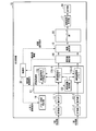
- FIG. 1 is a block diagram showing a functional configuration of a transmission device 10 according to the first embodiment.
- the transmission apparatus 10 according to the first embodiment receives a plurality of signals transmitted from the transmission apparatus on the transmission side through the 0-system transmission path and the 1-system transmission path, respectively, and selects one of the received transmission paths.
- the signal received at is transmitted to another device.
- the transmission device 10 includes receiving units 11-1 and 11-2, decoding units 12-1 and 12-2, a delay adjusting unit 13, a delay difference detecting unit 14, a route selecting unit 15, a demapping unit 16, and a transmission signal generating unit. 17, a transmitter 18, a memory connection controller 19, and a controller 20.
- the receiving unit 11-1 is an interface that receives a signal from the 0-system transmission line.
- the reception unit 11-2 is an interface that receives a signal from the 1-system transmission path.
- the decoding unit 12-1 restores the OTU frame from the received electric signal, establishes frame synchronization, and then outputs the restored OTU frame to the delay adjustment unit 13.
- the OTU frame may be any of OTU (Optical-channel Transport Unit) 1, OTU2, OTU3, and OTU4.
- the decoding unit 12-2 restores the OTU frame from the received electric signal, establishes frame synchronization, and then outputs the restored OTU frame to the delay adjustment unit 13.
- the delay adjustment unit 13 adjusts the delay between the 0-system transmission line and the 1-system transmission line. Specifically, the delay adjusting unit 13 adjusts the output of the same signal received by the 0-system transmission line and the 1-system transmission line, according to an instruction from the control unit 20. For example, the delay adjustment unit 13 adjusts the delay by adjusting the reading speed of the memory. The delay adjusting unit 13 adjusts until there is no delay difference between the 0-system transmission line and the 1-system transmission line.
- the delay adjustment unit 13 includes delay adjustment memories 131-1 and 131-2, a delay adjustment large capacity memory 132, and a delay adjustment control unit 133.
- the delay adjustment memory 131-1 accumulates the OTU frame output from the decoding unit 12-1 and outputs the OTU frame using a FIFO (First In First Out) method.
- the delay adjustment memory 131-1 is a memory having a small capacity, for example, a memory having no capacity for adjusting the maximum path difference (delay difference) between the 0-system transmission path and the 1-system transmission path.
- the delay adjustment memory 131-2 stores the OTU frame output from the decoding unit 12-2 and outputs the OTU frame using the FIFO method.
- the delay adjustment memory 131-2 is a memory having a small capacity, for example, a memory that does not have a capacity that allows a delay due to the maximum path difference (delay difference) between the 0-system transmission path and the 1-system transmission path. ..
- the capacity that can tolerate the delay due to the maximum path difference (delay difference) between the 0-system transmission path and the 1-system transmission path is the delay due to the maximum path difference (delay difference) between the 0-system transmission path and the 1-system transmission path. It is the capacity that can store all the data generated before it disappears.
- the delay adjustment memories 131-1 and 131-2 are referred to as the delay adjustment memory 131 unless otherwise specified.
- the delay adjusting large capacity memory 132 stores the OTU frame output from the decoding unit 12-1 or the decoding unit 12-2.
- the delay adjustment large capacity memory 132 is an auxiliary memory for accumulating a signal that cannot be accumulated in the delay adjustment memory 131-1 and the delay adjustment memory 131-2 due to insufficient capacity.
- the delay adjustment large-capacity memory 132 is a memory having a capacity that allows a delay due to the maximum path difference (delay difference) between the 0-system transmission path and the 1-system transmission path.
- the delay adjustment large-capacity memory 132 can switch the physical connection with the delay adjustment memory 131-1 and the delay adjustment memory 131-2.
- the connection destination may be switched under the control of the memory connection control unit 19, the connection destination may be switched by a switch, or the operator may physically switch the connection destination. Good.
- the delay adjustment large capacity memory 132 can be connected to either the delay adjustment memory 131-1 or the delay adjustment memory 131-2, and is not connected to the other memory.
- the delay adjustment large-capacity memory 132 may be an on-chip memory or an external memory outside the chip.
- the delay adjustment control unit 133 adds a delay to the signal by delaying the timing of reading the signal from the delay adjustment memory 131-1 and the delay adjustment memory 131-2 according to the delay amount control instruction notified from the control unit 20. Or delay the read by advancing the read timing to adjust the delay.
- the delay amount control instruction is a notification instructing to perform delay adjustment.
- the delay amount control instruction includes information on the delay difference between the 0-system transmission path and the 1-system transmission path.
- the delay adjustment control unit 133 reads out a signal from the delay adjustment memory 131-1 or the delay adjustment memory 131-2 to which the delay adjustment large capacity memory 132 is connected, and then the delay adjustment large capacity.
- the delay adjustment memory 131-1 or the delay adjustment memory 131-2 is instructed to store the signal stored in the memory 132 in its own memory.
- the delay adjustment control unit 133 directly reads a signal from the delay adjustment large-capacity memory 132 and connects the delay adjustment large-capacity memory 132 to the delay adjustment memory 131-1 or the delay adjustment memory 131-2. May be stored in.
- the delay adjustment control unit 133 cannot store a signal when the delay adjustment memory 131-1 or the delay adjustment memory 131-2 connected to the delay adjustment large-capacity memory 132 is insufficient in capacity or when the signal cannot be stored. If it is likely to be insufficient, the signal is accumulated in the delay adjustment large capacity memory 132.
- the delay adjustment control unit 133 does not store the signal in the delay adjustment memory 131-1 or the delay adjustment memory 131-2 to which the delay adjustment large capacity memory 132 is connected. The signal may be directly stored in the.
- the delay difference detection unit 14 calculates the delay difference between the 0-system transmission path and the 1-system transmission path based on the OTU frames accumulated in the delay adjustment memory 131-1 and the delay adjustment memory 131-2. To do.
- the delay difference detection unit 14 outputs information including the calculated delay difference value (hereinafter, referred to as “delay difference information”) to the control unit 20 and also outputs the OTU frame to the route selection unit 15.
- the delay difference detection unit 14 and the route selection unit 15 are connected by two routes, a first route and a second route.
- the first route is a route for outputting the OTU frames accumulated in the delay adjustment memory 131-1, that is, a route corresponding to the 0-system transmission line.
- the second route is a route for outputting the OTU frame accumulated in the delay adjustment memory 131-2, that is, a route corresponding to the 1-system transmission line.
- the route selection unit 15 selects the route from which the signal is acquired according to the route selection instruction notified from the control unit 20.
- the route selection instruction is an instruction to select a signal acquisition route.
- the route selection instruction includes information designating either the 0-system transmission path or the 1-system transmission path.
- the route selection unit 15 selects the first route when the route selection instruction includes the information designating the 0-system transmission line. Further, the route selection unit 15 selects the second route when the route selection instruction includes information designating the 1-system transmission route.
- the route selection unit 15 is a switch, and outputs the OTU frame output from the selected route to the demapping unit 16 by switching the connection to the selected route according to an instruction from the control unit 20.
- the demapping unit 16 restores the client signal by terminating the OH (Over Head) in the OTU frame output from the route selection unit 15. For example, when the type of the OTU frame is OTU4, the demapping unit 16 restores the 100GE client signal from the payload of the OTU frame.
- the transmission signal generation unit 17 generates the transmission signal by performing OH insertion processing on the client signal restored by the demapping unit 16 and then converting the client signal into an electric signal for transmission.
- the transmission unit 18 electro-optically converts the transmission signal generated by the transmission signal generation unit 17, and then transmits the transmission signal to the outside of the transmission device 10.
- the memory connection control unit 19 controls the connection destination of the delay adjustment large capacity memory 132 according to the memory connection instruction notified from the control unit 20. More specifically, the memory connection control unit 19 switches the physical connection of the delay adjustment large-capacity memory 132 so that the signal of either the 0-system transmission path or the 1-system transmission path can be used for the delay adjustment large capacity. It is stored in the memory 132.
- the memory connection instruction is an instruction relating to the connection of the delay adjustment large capacity memory 132, and for example, the memory connection instruction includes information that specifies the delay adjustment memory 131 in the path that requires delay adjustment.
- the path requiring delay adjustment is a transmission path through which the same signal is received earlier.
- the information specifying the delay adjustment memory 131 may be, for example, identification information of the delay adjustment memory 131 or the name of the delay adjustment memory 131.
- the control unit 20 controls each functional unit of the transmission device 10. For example, the control unit 20 determines the transmission path on which the same signal is received earlier based on the delay difference information obtained from the delay difference detection unit 14. That is, the control unit 20 determines whether the signal of the transmission path of the 0-system transmission path or the 1-system transmission path is received earlier.
- control unit 20 generates a memory connection instruction based on the determination result based on the delay difference information.
- control unit 20 generates a delay amount control instruction based on the delay difference information.
- control unit 20 generates the route selection instruction based on the delay difference information and the fault information indicating the fault of the route.
- the failure in this specification includes not only a general failure that occurs unexpectedly but also a phenomenon such as a disconnection of a transmission line accompanying planned transmission line construction.
- the failure information may be input from the delay difference detection unit 14 or an external communication device operated by the operator.
- the delay difference detection unit 14 determines that the system is in failure and fails the failure information when the signal from the transmission path of the system cannot be acquired for a certain period of time. It may be output to the control unit 20.
- the control unit 20 also includes information indicating an abnormality of the optical signal detected by the receiving unit 11-1 and OTN-OH (OTU-OH, ODU-OH, OPU-OH) decoded by the decoding unit 12-1.
- the failure information may be obtained from the information.
- FIG. 2 is a flowchart showing the flow of processing of the transmission device 10 according to the first embodiment. It is assumed that the delay adjustment large capacity memory 132 is not connected to any of the delay adjustment memories 131-1 and 131-2 at the start of the process of FIG.
- the transmission device 10 receives signals in two systems (step S101). Specifically, the receiving unit 11-1 receives a signal from the 0-system transmission line. Further, the receiving unit 11-2 receives a signal from the 1-system transmission path. The receiving unit 11-1 optically-electrically converts the received signal and outputs the signal after the optical-electrical conversion to the decoding unit 12-1. Further, the receiving unit 11-2 optically-electrically converts the received signal and outputs the signal after the optical-electrical conversion to the decoding unit 12-2 (step S102).
- the decoding unit 12-1 restores the OTU frame from the received electric signal.
- the decoding unit 12-1 stores the restored OTU frame in the delay adjustment memory 131-1 after establishing the frame synchronization. Further, the decoding unit 12-2 restores the OTU frame from the received electric signal (step S103). After establishing the frame synchronization, the decoding unit 12-2 stores the restored OTU frame in the delay adjustment memory 131-2.
- the delay difference detection unit 14 calculates the delay difference between the 0-system transmission path and the 1-system transmission path based on the OTU frames accumulated in the delay adjustment memory 131-1 and the delay adjustment memory 131-2. (Step S104). Specifically, the delay difference detection unit 14 respectively acquires the OTU frame stored in the delay adjustment memory 131-1 and the OTU frame stored in the delay adjustment memory 131-2. The delay difference detection unit 14 detects the MFAS from each of the acquired OTU frames and establishes the MFAS synchronization. Next, the delay difference detection unit 14 compares the MFAS value in the OTU frame acquired from the delay adjustment memory 131-1 with the MFAS value in the OTU frame acquired from the delay adjustment memory 131-2. Calculate the delay difference.
- the delay difference detection unit 14 defines and uses an arbitrary area of OH of an OTN (Optical Transport Network) frame as an extended MFAS when the delay using only the counter using the MFAS value is insufficient. good.
- the delay difference detection unit 14 outputs the calculated delay difference information to the control unit 20 and also outputs the OTU frame to the route selection unit 15.
- the delay difference detection unit 14 compares the OTU frame acquired from the delay adjustment memory 131-1 with the TTI (Trial Trace Identifier) in the OTU frame acquired from the delay adjustment memory 131-2, thereby receiving the signal. Data identity check may be performed.
- the control unit 20 determines the transmission path on which the same signal is received earlier based on the delay difference information output from the delay difference detection unit 14 (step S105).
- the control unit 20 generates a memory connection instruction according to the determination result, and outputs the generated memory connection instruction to the memory connection control unit 19.
- the control unit 20 determines that the signal of the 0-system transmission line is received earlier than the signal of the 1-system transmission line, the delay adjustment memory 131 that accumulates the signal received from the 0-system transmission line, that is, the delay adjustment memory 131 A memory connection instruction including an instruction to connect the delay adjustment large capacity memory 132 to the adjustment memory 131-1 is generated. Then, the control unit 20 outputs the generated memory connection instruction to the memory connection control unit 19.
- the control unit 20 determines that the signal of the 1-system transmission line is received earlier than the signal of the 0-system transmission line, the delay adjustment memory 131 that accumulates the signal received from the 1-system transmission line, That is, a memory connection instruction including an instruction to connect the delay adjustment large capacity memory 132 to the delay adjustment memory 131-2 is generated. Then, the control unit 20 outputs the generated memory connection instruction to the memory connection control unit 19.
- the memory connection control unit 19 connects the delay adjustment large capacity memory 132 to either the delay adjustment memory 131-1 or the delay adjustment memory 131-2 according to the memory connection instruction output from the control unit 20 ( Step S106). For example, when the memory connection instruction includes an instruction to connect the delay adjustment large capacity memory 132 to the delay adjustment memory 131-1, the memory connection control unit 19 sets the delay adjustment large capacity memory 132 for delay adjustment. Connect to the memory 131-1. Further, for example, if the memory connection instruction includes an instruction to connect the delay adjustment large capacity memory 132 to the delay adjustment memory 131-2, the memory connection control unit 19 delays the delay adjustment large capacity memory 132. Connect to the adjustment memory 131-2.
- the memory connection control unit 19 responds to the control unit 20 that the delay adjustment large capacity memory 132 is connected. After receiving the response that the delay adjustment mass memory 132 is connected, the control unit 20 generates a delay amount control instruction, and outputs the generated delay amount control instruction to the delay adjustment control unit 133 (step S107).
- the delay adjustment control unit 133 performs the delay adjustment by adjusting the memory read speed or the like according to the delay amount control instruction output from the control unit 20 (step S108).
- the delay difference detection unit 14 determines whether or not it is detected that the delay difference has disappeared (step S109). When the delay difference detection unit 14 detects that the delay difference has disappeared (step S109-YES), it notifies the control unit 20 that the delay difference has disappeared. On the other hand, when the delay difference detection unit 14 does not detect that the delay difference has disappeared (step S109-NO), it waits until it detects that the delay difference has disappeared.
- the control unit 20 When the delay difference detection unit 14 notifies that the delay difference is gone, the control unit 20 outputs an instruction to the delay adjustment control unit 133 to end the delay adjustment. As a result, the delay adjustment control unit 133 ends the delay adjustment. Further, the control unit 20 outputs a route selection instruction to the route selection unit 15 after the delay difference disappears. For example, the control unit 20 generates a route selection instruction including information designating a transmission path with a small delay, that is, a signal is received early, and outputs the generated route selection instruction to the route selection unit 15. Note that the control unit 20 specifies a transmission path different from the transmission path indicated by the failure information when the failure difference information is input from the delay difference detection unit 14 or when the operator inputs the failure information from an external communication device. A route selection instruction including information to be generated is generated, and the generated route selection instruction is output to the route selection unit 15.
- the route selection unit 15 selects the route from which the signal is acquired according to the route selection instruction (step S110).
- the route selection unit 15 includes information designating the 0-system transmission line in the route selection instruction, and is connected to the route of the 0-system transmission line (first route) at the time of acquisition of the route selection instruction.
- the first route is selected, but operations such as connection switching are not performed. In this way, when the route specified by the route selection instruction and the route connected at the time of acquisition of the route selection instruction are the same, the route selection unit 15 does not switch the route.
- the route selection unit 15 includes information designating the 0-system transmission line in the route selection instruction, and is connected to the 1-system transmission route (second route) at the time of acquisition of the route selection instruction. In this case, the first route is selected and the connection destination is switched from the second route to the first route. In this way, when the route designated by the route selection instruction and the route connected at the time of acquisition of the route selection instruction are different, the route selection unit 15 switches the route.
- the OTU frame is output to the demapping unit 16 from the route where the route selection unit 15 and the delay difference detection unit 14 are connected.
- the demapping unit 16 restores a predetermined client signal (for example, a 100GE client signal) from the payload after performing OH termination processing on the OTU frame output from the route selection unit 15 (step S111).
- the demapping unit 16 outputs the restored client signal to the transmission signal generation unit 17.
- the transmission signal generation unit 17 performs the OH insertion process on the client signal restored by the demapping unit 16 and then generates the transmission signal by converting it into an electric signal for transmission (step S112).
- the transmission signal generator 17 outputs the generated transmission signal.
- the transmission unit 18 electro-optically converts the transmission signal generated by the transmission signal generation unit 17, and then transmits the transmission signal to the outside of the transmission device 10 (step S113).
- the connection of the delay adjustment large capacity memory 132 is switched based on the delay difference between the 0-system transmission path and the 1-system transmission path.
- the transmission device 10 controls the delay adjustment large-capacity memory 132 to be connected to the delay adjustment memory 131 of the transmission line that requires delay adjustment, that is, the transmission line in which the same signal was received earlier. ..
- one large-capacity memory having a capacity capable of adjusting the delay due to the maximum path difference (delay difference) between the 0-system transmission path and the 1-system transmission path can be provided and shared. Therefore, it is not necessary to provide such a large capacity memory for each transmission path. Therefore, the total memory capacity can be reduced. As a result, the cost of the device can be suppressed.
- connection is switched to the transmission path before the path switching from the situation in which the communication is performed on either the 0-system transmission path or the 1-system transmission path after the path switching is performed (hereinafter, This is an embodiment that solves the problem at the time of "switching back the route.” That is, in the second embodiment, when communication is performed on the 0-system transmission path after the path switching is performed, the connection is switched to the 1-system transmission path that is the transmission path before the path switching, and after the path switching is performed. This is an embodiment that solves the problem when switching the connection to the 0-system transmission path, which is the transmission path before the path switching, when communication is performed on the 1-system transmission path.
- the path selecting unit 15 causes the delay adjustment large-capacity memory 132 to be connected to the delay adjustment memory 131-1 in the 0-system transmission line to change the system from the 1-system transmission line to the 0-system transmission line. If an attempt is made to switch the route back to the transmission line, data will be discarded due to insufficient memory capacity in the delay adjustment memory 131-2 in the system 1 transmission line when the delay adjustment is performed. Therefore, in the second embodiment, a method for avoiding such a problem will be described.
- FIG. 3 is a block diagram showing a functional configuration of the transmission device 10a according to the second embodiment.
- the transmission device 10a according to the second embodiment performs the same process as the transmission device 10.
- the transmission device 10a switches the route back at a predetermined timing after executing the route switching.
- the predetermined timing is, for example, the timing at which the communication of the failed route is restored or the timing at which the operator gives an instruction.
- the transmission device 10a includes receiving units 11-1 and 11-2, decoding units 12-1 and 12-2, a delay adjusting unit 13, a delay difference detecting unit 14, a route selecting unit 15, a demapping unit 16, and a transmission signal generating unit. 17, a transmission unit 18, a memory connection control unit 19a and a control unit 20a.
- the transmission device 10a differs from the transmission device 10 in that it includes a memory connection control unit 19a and a control unit 20a instead of the memory connection control unit 19 and the control unit 20.
- the transmission device 10a is similar to the transmission device 10 in other configurations. Therefore, the description of the entire transmission device 10a is omitted, and the memory connection control unit 19a and the control unit 20a will be described.
- the memory connection control unit 19a performs the same processing as the memory connection control unit 19. In addition, the memory connection control unit 19a disconnects the delay adjustment large-capacity memory 132 connected to the delay adjustment memory 131 after performing the path switching. Specifically, the memory connection control unit 19a physically disconnects the connection between the delay adjustment memory 131 and the delay adjustment large capacity memory 132.
- the control unit 20a performs the same processing as the control unit 20. Further, the control unit 20a issues a memory connection instruction including an instruction to release the connection of the delay adjustment large capacity memory 132 after the route switching is performed, that is, after the route is switched by the route selection unit 15. Output to. Further, the control unit 20a outputs a route selection instruction including an instruction to connect to the route before switching to the route selection unit 15 after the delay difference is eliminated by the delay adjustment.
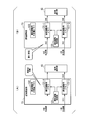
- FIG. 4 and 5 are diagrams for explaining the processing of the transmission device 10a according to the second embodiment.
- the connection control unit 19a disconnects the delay adjustment memory 131-1 and the delay adjustment large capacity memory 132 on the 0-system transmission line.
- the delay difference detection unit 14 sets the MFAS value in the OTU frame acquired from the delay adjustment memory 131-1 , The delay difference is calculated by comparing the MFAS value in the OTU frame acquired from the delay adjustment memory 131-2.
- the memory connection control unit 19a is a transmission line with less delay as shown in FIG.
- the delay adjusting large capacity memory 132 is reconnected to the delay adjusting memory 131-2 in the system transmission line. Then, after the delay difference is detected by the delay difference detection unit 14 to eliminate the delay difference, the path selection unit 15 switches back from the 1-system transmission line to the 0-system transmission line.
- FIG. 6 is a flowchart showing a processing flow of the transmission device 10a according to the second embodiment.
- the process of FIG. 6 is executed after the route is switched by the route selection unit 15.
- the control unit 20a generates a memory connection instruction including an instruction to release the connection of the delay adjustment large-capacity memory 132 after the path is switched by the path selection unit 15.
- the control unit 20a outputs the generated memory connection instruction to the memory connection control unit 19a.
- the memory connection control unit 19a disconnects the delay adjustment memory 131 and the delay adjustment large capacity memory 132 according to the memory connection instruction output from the control unit 20a (step S201).
- the memory connection control unit 19a connects the delay adjustment memory 131-1 and the delay adjustment large-capacity memory 132 to each other. Disconnect.
- the memory connection control unit 19a determines that the delay adjustment memory 131-2 and the delay adjustment large capacity memory are connected. The connection with 132 is disconnected. As a result, the delay adjustment large-capacity memory 132 is in a state in which it is not connected to any of the delay adjustment memories 131-1 and 131-2.
- the control unit 20a detects the recovery of the transmission line by the notification indicating the failure recovery from the delay difference detection unit 14 or the switchback instruction from the operator (step S202).
- the delay difference detection unit 14 calculates the delay difference between the 0-system transmission path and the 1-system transmission path based on the OTU frames accumulated in the delay adjustment memory 131-1 and the delay adjustment memory 131-2. Yes (step S203).
- the control unit 20a determines the transmission path on which the same signal is received earlier based on the delay difference information output from the delay difference detection unit 14 (step S204).
- the control unit 20a generates a memory connection instruction according to the determination result, and outputs the generated memory connection instruction to the memory connection control unit 19a.
- control unit 20a determines that the signal of the 0-system transmission line is received earlier than the signal of the 1-system transmission line, the control unit 20a accumulates the signal received from the 0-system transmission line, that is, the delay adjustment memory 131, that is, delay A memory connection instruction including an instruction to connect the delay adjustment large capacity memory 132 to the adjustment memory 131-1 is generated. Then, the control unit 20a outputs the generated memory connection instruction to the memory connection control unit 19a.
- the control unit 20a determines that the signal of the 1-system transmission path is received earlier than the signal of the 0-system transmission path, the delay adjustment memory 131 that accumulates the signal received from the 1-system transmission path, That is, a memory connection instruction including an instruction to connect the delay adjustment large capacity memory 132 to the delay adjustment memory 131-2 is generated. Then, the control unit 20a outputs the generated memory connection instruction to the memory connection control unit 19a.
- the memory connection control unit 19a connects the delay adjustment large capacity memory 132 to either the delay adjustment memory 131-1 or the delay adjustment memory 131-2 according to the memory connection instruction output from the control unit 20a ( Step S205). For example, when the memory connection instruction includes an instruction to connect the delay adjustment large capacity memory 132 to the delay adjustment memory 131-1, the memory connection control unit 19a sets the delay adjustment large capacity memory 132 for delay adjustment. Connect to the memory 131-1. Further, for example, when the memory connection instruction includes an instruction to connect the delay adjustment large capacity memory 132 to the delay adjustment memory 131-2, the memory connection control unit 19a delays the delay adjustment large capacity memory 132. Connect to the adjustment memory 131-2.
- the memory connection control unit 19a responds to the control unit 20a that the delay adjustment large capacity memory 132 is connected. After receiving the response that the delay adjustment large capacity memory 132 is connected, the control unit 20a generates a delay amount control instruction, and outputs the generated delay amount control instruction to the delay adjustment control unit 133 (step S206).
- the delay adjustment control unit 133 performs the delay adjustment by adjusting the read speed of the memory or the like in accordance with the delay amount control instruction output from the control unit 20a (step S207).
- the delay difference detection unit 14 determines whether or not it is detected that the delay difference has disappeared (step S208). When the delay difference detection unit 14 detects that the delay difference has disappeared (step S208-YES), it notifies the control unit 20a that the delay difference has disappeared. On the other hand, if the delay difference detection unit 14 has not detected that the delay difference has disappeared (step S208-NO), it waits until it detects that the delay difference has disappeared.
- the control unit 20a When the delay difference detection unit 14 notifies that the delay difference is gone, the control unit 20a outputs an instruction to the delay adjustment control unit 133 to end the delay adjustment. As a result, the delay adjustment control unit 133 ends the delay adjustment. In addition, the control unit 20a outputs a route selection instruction to the route selection unit 15 after the delay difference disappears. For example, the control unit 20a generates a route selection instruction including information designating a transmission path with a small delay, that is, a signal is received early, and outputs the generated route selection instruction to the route selection unit 15. Note that the control unit 20a designates a transmission path different from the transmission path indicated by the failure information when the failure information is input from the delay difference detection unit 14 or when the operator inputs the failure information from an external communication device. A route selection instruction including information to be generated is generated, and the generated route selection instruction is output to the route selection unit 15.
- the route selection unit 15 selects the route from which the signal is acquired according to the route selection instruction (step S209).
- the route selection unit 15 includes information designating the 0-system transmission line in the route selection instruction, and is connected to the route of the 0-system transmission line (first route) at the time of acquisition of the route selection instruction. In this case, the first route is selected, but operations such as connection switching are not performed. In this way, when the route specified by the route selection instruction and the route connected at the time of acquisition of the route selection instruction are the same, the route selection unit 15 does not switch the route.
- the route selection unit 15 includes information designating the 0-system transmission line in the route selection instruction, and is connected to the 1-system transmission route (second route) at the time of acquisition of the route selection instruction. In this case, the first route is selected and the connection destination is switched from the second route to the first route. In this way, when the route designated by the route selection instruction and the route connected at the time of acquisition of the route selection instruction are different, the route selection unit 15 switches the route.
- the OTU frame is output to the demapping unit 16 from the route where the route selection unit 15 and the delay difference detection unit 14 are connected.
- the demapping unit 16 restores a predetermined client signal (for example, 100GE client signal) from the payload after performing the OH termination process in the OTU frame output from the route selection unit 15 (step S210).
- the demapping unit 16 outputs the restored client signal to the transmission signal generation unit 17.
- the transmission signal generation unit 17 performs the OH insertion process on the client signal restored by the demapping unit 16 and then generates the transmission signal by converting it into an electric signal for transmission (step S211).
- the transmission signal generator 17 outputs the generated transmission signal.
- the transmission unit 18 electro-optically converts the transmission signal generated by the transmission signal generation unit 17, and then transmits the transmission signal to the outside of the transmission device 10 (step S212).
- connection relationship of the delay adjustment large capacity memory 132 before and after the path switching will be described with a specific example.
- the process of connecting the delay adjusting large capacity memory 132 before switching the route is the process of steps S103 to S106 in FIG. 2, and the process of connecting the delay adjusting large capacity memory 132 after switching the route. Is the processing of steps S201 to S206 in FIG.
- the connection operation of the delay adjustment large capacity memory 132 in the above four patterns will be described in detail.
- the pattern 1) will be described.
- the pattern of 1) is determined that the signal of the 0-system transmission line is received earlier than the signal of the 1-system transmission line in the process of step S105 of FIG. 2, and the 0-system transmission line is processed in the process of step S204 of FIG. This is the case where it is determined that the signal of 1 is received earlier than the signal of the 1-system transmission line.
- the memory connection control unit 19a connects the delay adjustment large capacity memory 132 to the delay adjustment memory 131-1 in the 0-system transmission path with a small delay.
- the memory connection control unit 19a connects the delay adjustment large capacity memory 132 again to the delay adjustment memory 131-1 in the 0-system transmission path with the smaller delay.
- the pattern 2) it is determined that the signal of the 1-system transmission line is received earlier than the signal of the 0-system transmission line in the process of step S105 of FIG. 2, and the 1-system transmission line is processed in the process of step S204 of FIG. This is the case where it is determined that the signal of 1 is received earlier than the signal of the 0-system transmission line.
- the memory connection control unit 19a connects the delay adjustment large-capacity memory 132 to the delay adjustment memory 131-2 in the 1-system transmission path with less delay in the process of step S106. Then, in the process of step S205, the memory connection control unit 19a reconnects the delay adjustment large capacity memory 132 to the delay adjustment memory 131-2 in the 1-system transmission path with less delay.
- the pattern of 3 it is determined that the signal of the 0-system transmission line is received earlier than the signal of the 1-system transmission line in the process of step S105 of FIG. 2, and the 1-system transmission line is processed in the process of step S204 of FIG. This is the case where it is determined that the signal of 1 is received earlier than the signal of the 0-system transmission line.
- the memory connection control unit 19a connects the delay adjustment large capacity memory 132 to the delay adjustment memory 131-1 in the 0-system transmission path with a small delay.
- the memory connection control unit 19a connects the delay adjustment large capacity memory 132 to the delay adjustment memory 131-2 in the 1-system transmission path with a small delay.
- the connection destination of the delay adjustment large-capacity memory 132 is switched before and after the path switching. As a result, it is possible to suppress the discarding of data due to overflow when adjusting the delay of a transmission path with a small delay.
- the pattern of 4 it is determined that the signal of the 1-system transmission line is received earlier than the signal of the 0-system transmission line in the process of step S105 of FIG. 2, and the 0-system transmission line is processed in the process of step S204 of FIG. This is the case where it is determined that the signal of 1 is received earlier than the signal of the 1-system transmission line.
- the memory connection control unit 19a connects the delay adjustment large-capacity memory 132 to the delay adjustment memory 131-2 in the 1-system transmission path with less delay in the process of step S106.
- the memory connection control unit 19a connects the delay adjustment large capacity memory 132 to the delay adjustment memory 131-1 in the 0-system transmission path with the smaller delay.
- the connection destination of the delay adjustment large capacity memory 132 is switched before and after the path switching. As a result, it is possible to suppress the discarding of data due to overflow when adjusting the delay of a transmission path with a small delay.
- the transmission device 10a configured as described above, the same effect as that of the first embodiment can be obtained.
- the transmission device 10a connects the delay adjustment memory 131 and the delay adjustment large capacity memory 132 until a predetermined timing elapses after performing the path switching as in the first embodiment. Disconnect. Then, the transmission device 10a calculates the delay difference between the 0-system transmission line and the 1-system transmission line after a predetermined timing has elapsed, and stores the delay adjustment large memory in the delay adjustment memory 131 of the transmission line with a small delay.
- the capacity memory 132 is reconnected. As a result, it is possible to suppress data discard due to insufficient memory capacity.
- the third embodiment is an embodiment in which the control unit included in the transmission device is installed in another system.
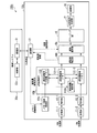
- FIG. 7 is a diagram showing a system configuration of the transmission system 100b in the third embodiment.
- the transmission system 100b includes a transmission device 10b and a control system 30.
- the communication between the transmission device 10b and the control system 30 may be wired communication or wireless communication.
- the transmission device 10b receives a plurality of signals transmitted from the transmission device on the transmission side through the 0-system transmission path and the 1-system transmission path, respectively, and receives the signal received through any one of the received plurality of signals. Transmit to another device.
- the transmission device 10b performs connection of the large-capacity memory for delay adjustment, delay adjustment, and path selection according to an instruction from the control system 30.
- the control system 30 controls the transmission device 10b by instructing the transmission device 10b to connect the delay adjustment large-capacity memory, delay adjustment, and select a route based on the information obtained from the transmission device 10b.
- the control system 30 is provided, for example, at a place different from the place where the transmission device 10b is installed and where the operator is located.
- the transmission device 10b includes receiving units 11-1 and 11-2, decoding units 12-1 and 12-2, a delay adjusting unit 13b, a delay difference detecting unit 14b, a route selecting unit 15b, a demapping unit 16, and a transmission signal generating unit. 17, a transmission unit 18, a memory connection control unit 19b, and a communication unit 21.
- the transmission device 10b includes a delay adjusting unit 13b, a delay difference detecting unit 14b, a route selecting unit 15b, and a memory connection controlling unit 19b instead of the delay adjusting unit 13, the delay difference detecting unit 14, the route selecting unit 15, and the memory connection controlling unit 19.
- the configuration differs from the transmission device 10 in that the transmission device 10 is provided, the control unit 20 is not provided, and the communication unit 21 is newly provided.
- the transmission device 10b is similar to the transmission device 10 in other configurations. Therefore, the description of the entire transmission device 10b is omitted, and the delay adjustment unit 13b, the delay difference detection unit 14b, the route selection unit 15b, the memory connection control unit 19b, and the communication unit 21 will be described.
- the communication unit 21 communicates with the control system 30.
- the communication unit 21 transmits the delay difference information to the control system 30, and receives the memory connection instruction, the delay amount control instruction, and the route selection instruction from the control system 30.
- the delay adjusting unit 13b performs the same operation as the delay adjusting unit 13.
- the operation performed by the delay adjustment unit 13b differs from the operation performed by the delay adjustment unit 13 in that the operation is performed based on an instruction transmitted from the control system 30 instead of an instruction from the control unit 20.
- the delay difference detection unit 14b performs the same operation as the delay difference detection unit 14.
- the operation performed by the delay difference detection unit 14b differs from the operation performed by the delay difference detection unit 14 in that the delay difference information is output to the control system 30 via the communication unit 21 instead of being output to the control unit 20. This is the output point.
- the route selection unit 15b performs the same operation as the route selection unit 15.
- the operation performed by the route selection unit 15b differs from the operation performed by the route selection unit 15 in that the operation is performed based on an instruction transmitted from the control system 30 instead of an instruction from the control unit 20.
- the memory connection control unit 19b performs the same operation as the memory connection control unit 19.
- the operation performed by the memory connection control unit 19b is different from the operation performed by the memory connection control unit 19 in that the operation is performed based on the instruction transmitted from the control system 30 instead of the instruction from the control unit 20.
- the control system 30 includes a communication unit 31 and a control unit 32.
- the communication unit 31 communicates with the transmission device 10b.
- the communication unit 31 receives the delay difference information from the transmission device 10b, and transmits a memory connection instruction, a delay amount control instruction, and a route selection instruction to the transmission device 10b.
- the control unit 32 controls the transmission device 10b based on the information obtained from the transmission device 10b. For example, the control unit 32 determines the transmission path on which the same signal is received earlier based on the delay difference information obtained from the transmission device 10b. That is, the control unit 32 determines whether the signal of the 0-system transmission path or the 1-system transmission path of the transmission device 10b is received earlier.
- control unit 32 generates a memory connection instruction based on the determination result based on the delay difference information. In addition, for example, the control unit 32 generates a delay amount control instruction based on the delay difference information. Further, for example, the control unit 32 generates the route selection instruction based on the delay difference information and the fault information indicating the fault of the route.
- FIG. 8 is a sequence diagram showing a processing flow of the transmission system 100b in the third embodiment. It is assumed that the delay adjustment large-capacity memory 132 is not connected to the delay adjustment memories 131-1 and 131-2 at the start of the process of FIG.
- the transmission device 10b receives signals in two systems (step S301). Specifically, the receiving unit 11-1 receives a signal from the 0-system transmission line. Further, the receiving unit 11-2 receives a signal from the 1-system transmission path. The receiving unit 11-1 optically-electrically converts the received signal and outputs the signal after the optical-electrical conversion to the decoding unit 12-1. The receiving unit 11-2 also performs optical-electric conversion on the received signal and outputs the signal after the optical-electric conversion to the decoding unit 12-2 (step S302).
- the decoding unit 12-1 restores the OTU frame from the received electric signal.
- the decoding unit 12-1 stores the restored OTU frame in the delay adjustment memory 131-1 after establishing the frame synchronization. Further, the decoding unit 12-2 restores the OTU frame from the received electric signal (step S303). After establishing the frame synchronization, the decoding unit 12-2 stores the restored OTU frame in the delay adjustment memory 131-2.
- the delay difference detection unit 14b calculates the delay difference between the 0-system transmission path and the 1-system transmission path based on the OTU frames accumulated in the delay adjustment memory 131-1 and the delay adjustment memory 131-2. (Step S304).
- the method for calculating the delay difference is the same as that in the first embodiment, and thus the description thereof is omitted.
- the delay difference detection unit 14b outputs the calculated delay difference information to the communication unit 21 and also outputs the OTU frame to the route selection unit 15b.
- the communication unit 21 transmits the delay difference information output from the delay difference detection unit 14b to the control system 30 (step S305).
- the communication unit 31 of the control system 30 receives the delay difference information transmitted from the transmission device 10b.
- the communication unit 31 outputs the received delay difference information to the control unit 32.
- the control unit 32 determines the transmission path on which the same signal is received earlier based on the delay difference information output from the communication unit 31 (step S306).
- the control unit 32 generates a memory connection instruction according to the determination result, and outputs the generated memory connection instruction to the communication unit 31.
- the communication unit 31 transmits the memory connection instruction output from the control unit 32 to the transmission device 10b (step S307).
- the communication unit 21 of the transmission device 10b receives the memory connection instruction transmitted from the control system 30.
- the communication unit 21 outputs the received memory connection instruction to the memory connection control unit 19b.
- the memory connection control unit 19b connects the delay adjustment large capacity memory 132 to either the delay adjustment memory 131-1 or the delay adjustment memory 131-2 according to the memory connection instruction output from the communication unit 21 ( Step S308).
- the memory connection control unit 19b uses the delay adjustment large capacity memory 132 for delay adjustment. Connect to the memory 131-1. Also, for example, when the memory connection instruction includes an instruction to connect the delay adjustment large capacity memory 132 to the delay adjustment memory 131-2, the memory connection control unit 19b delays the delay adjustment large capacity memory 132. Connect to the adjustment memory 131-2.
- the memory connection control unit 19b When the connection between the delay adjustment memory 131 and the delay adjustment large capacity memory 132 is completed, the memory connection control unit 19b generates a response indicating that the delay adjustment large capacity memory 132 is connected, and causes the communication unit 21 to operate. Sends a response to the control system 30 via.
- the communication unit 31 of the control system 30 receives the response transmitted from the transmission device 10b and outputs the received response to the control unit 32.
- the control unit 32 After receiving the response that the delay adjusting large capacity memory 132 is connected, the control unit 32 generates a delay amount control instruction and outputs the generated delay amount control instruction to the communication unit 31 (step S309).
- the communication unit 31 transmits the delay amount control instruction output from the control unit 32 to the transmission device 10b (step S310).
- the communication unit 21 of the transmission device 10b receives the delay amount control instruction transmitted from the control system 30.
- the communication unit 21 outputs the received delay amount control instruction to the delay adjustment control unit 133b.
- the delay adjustment control unit 133b performs the delay adjustment by adjusting the memory read speed or the like according to the delay amount control instruction output from the communication unit 21 (step S311).
- the delay difference detection unit 14b detects that the delay difference has disappeared (step S312)
- the delay difference detection unit 14b generates a notification indicating that the delay difference has disappeared, and outputs the generated notification to the communication unit 21.
- the communication unit 21 transmits the notification output from the delay difference detection unit 14b to the control system 30 (step S313).
- the communication unit 31 of the control system 30 receives the notification transmitted from the transmission device 10b.
- the communication unit 31 outputs the received notification to the control unit 32.
- the control unit 32 When detecting that the delay difference has disappeared in the notification output from the communication unit 31, the control unit 32 generates a delay adjustment end instruction including an instruction to end the delay adjustment.
- the control unit 32 outputs the generated delay adjustment end instruction to the communication unit 31.
- the communication unit 31 transmits the delay adjustment end instruction output from the control unit 32 to the transmission device 10b (step S314).
- the communication unit 21 of the transmission device 10b receives the delay adjustment end instruction transmitted from the control system 30.
- the communication unit 21 outputs the received delay adjustment end instruction to the delay adjustment control unit 133b.
- the delay adjustment control unit 133b ends the delay adjustment (step S315).
- the control unit 32 of the control system 30 generates the route selection instruction after the delay adjustment end instruction is transmitted.
- the control unit 32 generates a route selection instruction including information designating a transmission path with a small delay, that is, a signal is received early, and outputs the generated route selection instruction to the communication unit 31.
- the communication unit 31 transmits the route selection instruction output from the control unit 32 to the transmission device 10b (step S316).
- the communication unit 21 of the transmission device 10b receives the route selection instruction transmitted from the control system 30.
- the communication unit 21 outputs the received route selection instruction to the route selection unit 15b.
- the route selection unit 15b selects the route from which the signal is acquired according to the route selection instruction output from the communication unit 21 (step S317).
- the route selecting unit 15b includes information designating the 0-system transmission line in the route selection instruction, and is connected to the route of the 0-system transmission line (first route) when the route selection instruction is acquired. In this case, the first route is selected, but operations such as connection switching are not performed. In this way, when the route specified by the route selection instruction and the route connected at the time of acquisition of the route selection instruction are the same, the route selection unit 15b does not switch the route.
- the route selecting unit 15b includes information designating the 0-system transmission line in the route selection instruction, and is connected to the route of the 1-system transmission line (second route) at the time of acquisition of the route selection instruction. In this case, the first route is selected and the connection destination is switched from the second route to the first route. In this way, when the route designated by the route selection instruction and the route connected at the time of acquisition of the route selection instruction are different, the route selection unit 15b switches the routes.
- the OTU frame is output to the demapping unit 16 from the route in which the route selection unit 15b and the delay difference detection unit 14b are connected.
- the demapping unit 16 performs OH termination processing on the OTU frame output from the route selection unit 15, and then restores a predetermined client signal (for example, 100GE client signal) from the payload (step S318).
- the demapping unit 16 outputs the restored client signal to the transmission signal generation unit 17.
- the transmission signal generation unit 17 performs OH insertion processing on the client signal restored by the demapping unit 16 and then converts the client signal into an electric signal for transmission to generate a transmission signal (step S319).
- the transmission signal generator 17 outputs the generated transmission signal.
- the transmission unit 18 electro-optically converts the transmission signal generated by the transmission signal generation unit 17, and then transmits the transmission signal to the outside of the transmission device 10 (step S320).
- the same effect as that of the first embodiment can be obtained.
- some functional units of the transmission device 10 according to the first embodiment are mounted in another system.
- the processing load on the transmission device 10b can be reduced as compared with the first embodiment.
- control system 30 has been shown to control one transmission device 10b, but the control system 30 may be configured to control a plurality of transmission devices 10b.
- the fourth embodiment has a configuration in which a control unit included in a transmission device is mounted in another system, and communication is performed using either a 0-system transmission path or a 1-system transmission path after performing path switching.
- This is an embodiment for solving the problem when switching the connection to the transmission path before the path switching (hereinafter, referred to as "path switchback") from the situation in which the operation is performed.
- FIG. 9 is a diagram showing a system configuration of the transmission system 100c in the fourth embodiment.
- the transmission system 100c includes a transmission device 10c and a control system 30c.
- the transmission device 10c performs the same process as the transmission device 10b. Further, the transmission device 10c performs path switching back at a predetermined timing after executing path switching.
- the control system 30c performs the same process as the control system 30. In addition, the control system 30c, after executing the route switching, instructs the transmission device 10c to switch back the route at a predetermined timing.
- the transmission device 10c includes receiving units 11-1 and 11-2, decoding units 12-1 and 12-2, a delay adjusting unit 13b, a delay difference detecting unit 14b, a route selecting unit 15b, a demapping unit 16, and a transmission signal generating unit. 17, a transmitter 18, and a memory connection controller 19c.
- the transmission device 10c differs from the transmission device 10b in that it includes a memory connection control unit 19c instead of the memory connection control unit 19b.
- the transmission device 10c is similar to the transmission device 10b in other configurations. Therefore, the description of the entire transmission device 10c is omitted, and the memory connection control unit 19c will be described.
- the memory connection control unit 19c performs the same processing as the memory connection control unit 19b. Further, the memory connection control unit 19c disconnects the delay adjustment large capacity memory 132 connected to the delay adjustment memory 131 after the path switching is performed. Specifically, the memory connection control unit 19c physically disconnects the connection between the delay adjustment memory 131 and the delay adjustment large capacity memory 132.
- the control system 30c includes a communication unit 31 and a control unit 32c.
- the control unit 32c performs the same process as the control unit 32. Further, the control unit 32c sends a memory connection instruction including an instruction to release the connection of the delay adjustment large-capacity memory 132 to the communication unit 31 after the route switching is performed, that is, after the route selection unit 15 switches the route. It transmits to the transmission apparatus 10c via.
- the control unit 20c transmits a route selection instruction including an instruction to connect to the route before switching to the transmission device 10c via the communication unit 31 after the delay difference is eliminated by the delay adjustment.
- FIG. 10 is a sequence diagram showing a processing flow of the transmission system 100c in the fourth embodiment.
- the process of FIG. 10 is performed after the route is switched by the route selection unit 15.
- the control unit 32c of the control system 30c generates a memory connection instruction including an instruction to disconnect the delay adjustment large capacity memory 132 after the path is switched in the transmission device 10c.
- the control unit 32c outputs the generated memory connection instruction to the communication unit 31.
- the communication unit 31 transmits the memory connection instruction output from the control unit 32 to the transmission device 10c (step S401).
- the communication unit 21 of the transmission device 10c receives the memory connection instruction transmitted from the control system 30c.
- the communication unit 21 outputs the received memory connection instruction to the memory connection control unit 19c.
- the memory connection control unit 19c disconnects the delay adjustment memory 131 and the delay adjustment large capacity memory 132 according to the memory connection instruction output from the communication unit 21 (step S402).
- the memory connection control unit 19c determines that the delay adjustment memory 131-1 and the delay adjustment large-capacity memory 132 are connected to each other. Disconnect. Further, for example, when the delay adjustment memory 131-2 and the delay adjustment large capacity memory 132 are connected, the memory connection control unit 19c determines that the delay adjustment memory 131-2 and the delay adjustment large capacity memory are connected. The connection with 132 is disconnected. As a result, the delay adjustment large-capacity memory 132 is in a state in which it is not connected to any of the delay adjustment memories 131-1 and 131-2.
- the delay difference detection unit 14b detects the restoration of the transmission path (step S403), it determines that the transmission path is the 0-system transmission path based on the OTU frames stored in the delay adjustment memory 131-1 and the delay adjustment memory 131-2. A delay difference with the 1-system transmission path is calculated (step S404). The method for calculating the delay difference is the same as that in the first embodiment, and thus the description thereof is omitted.
- the delay difference detection unit 14b outputs the calculated delay difference information to the communication unit 21 and also outputs the OTU frame to the route selection unit 15b.
- the communication unit 21 transmits the delay difference information output from the delay difference detection unit 14b to the control system 30c (step S405).
- the communication unit 31 of the control system 30c receives the delay difference information transmitted from the transmission device 10c.
- the communication unit 31 outputs the received delay difference information to the control unit 32c.
- the control unit 32c determines the transmission path on which the same signal is received earlier based on the delay difference information output from the communication unit 31 (step S406).
- the control unit 32c generates a memory connection instruction according to the determination result, and outputs the generated memory connection instruction to the communication unit 31.
- the communication unit 31 transmits the memory connection instruction output from the control unit 32c to the transmission device 10c (step S407).
- the communication unit 21 of the transmission device 10c receives the memory connection instruction transmitted from the control system 30c.
- the communication unit 21 outputs the received memory connection instruction to the memory connection control unit 19c.
- the memory connection control unit 19c connects the delay adjustment large capacity memory 132 to either the delay adjustment memory 131-1 or the delay adjustment memory 131-2 according to the memory connection instruction output from the communication unit 21 ( Step S408).
- the memory connection control unit 19c When the connection between the delay adjustment memory 131 and the delay adjustment large capacity memory 132 is completed, the memory connection control unit 19c generates a response indicating that the delay adjustment large capacity memory 132 is connected, and causes the communication unit 21 to operate. A response to the control system 30c via.
- the communication unit 31 of the control system 30c receives the response transmitted from the transmission device 10c and outputs the received response to the control unit 32c.
- the control unit 32c After receiving the response that the delay adjustment large capacity memory 132 is connected, the control unit 32c generates a delay amount control instruction, and outputs the generated delay amount control instruction to the communication unit 31 (step S409).
- the communication unit 31 transmits the delay amount control instruction output from the control unit 32c to the transmission device 10c (step S410).
- the communication unit 21 of the transmission device 10c receives the delay amount control instruction transmitted from the control system 30c.
- the communication unit 21 outputs the received delay amount control instruction to the delay adjustment control unit 133b.
- the delay adjustment control unit 133b performs the delay adjustment by adjusting the memory read speed or the like according to the delay amount control instruction output from the communication unit 21 (step S411).
- the delay difference detection unit 14b detects that the delay difference has disappeared (step S412)
- the delay difference detection unit 14b generates a notification indicating that the delay difference has disappeared, and outputs the generated notification to the communication unit 21.
- the communication unit 21 transmits the notification output from the delay difference detection unit 14b to the control system 30c (step S413).
- the communication unit 31 of the control system 30c receives the notification transmitted from the transmission device 10c.
- the communication unit 31 outputs the received notification to the control unit 32c.
- the control unit 32c When detecting that the delay difference has disappeared in the notification output from the communication unit 31, the control unit 32c generates a delay adjustment end instruction including an instruction to end the delay adjustment.
- the control unit 32c outputs the generated delay adjustment end instruction to the communication unit 31.
- the communication unit 31 transmits the delay adjustment end instruction output from the control unit 32c to the transmission device 10c (step S414).
- the communication unit 21 of the transmission device 10c receives the delay adjustment end instruction transmitted from the control system 30c.
- the communication unit 21 outputs the received delay adjustment end instruction to the delay adjustment control unit 133b.
- the delay adjustment control unit 133b ends the delay adjustment (step S415).
- the control unit 32c of the control system 30c generates the route selection instruction after the delay adjustment end instruction is transmitted.
- the control unit 32c generates a route selection instruction including information designating a transmission path with a small delay, that is, a signal is received early, and outputs the generated route selection instruction to the communication unit 31.
- the communication unit 31 transmits the route selection instruction output from the control unit 32c to the transmission device 10b (step S416).
- the communication unit 21 of the transmission device 10c receives the route selection instruction transmitted from the control system 30c.
- the communication unit 21 outputs the received route selection instruction to the route selection unit 15b.
- the route selection unit 15b selects the route from which the signal is acquired according to the route selection instruction output from the communication unit 21 (step S417).
- the route selecting unit 15b includes information designating the 0-system transmission line in the route selection instruction, and is connected to the route of the 0-system transmission line (first route) when the route selection instruction is acquired. In this case, the first route is selected, but operations such as connection switching are not performed. In this way, when the route specified by the route selection instruction and the route connected at the time of acquisition of the route selection instruction are the same, the route selection unit 15b does not switch the route.
- the route selecting unit 15b includes information designating the 0-system transmission line in the route selection instruction, and is connected to the route of the 1-system transmission line (second route) at the time of acquisition of the route selection instruction. In this case, the first route is selected and the connection destination is switched from the second route to the first route. In this way, when the route designated by the route selection instruction and the route connected at the time of acquisition of the route selection instruction are different, the route selection unit 15b switches the routes.
- the OTU frame is output to the demapping unit 16 from the route in which the route selection unit 15b and the delay difference detection unit 14b are connected.
- the demapping unit 16 restores a predetermined client signal (for example, a 100GE client signal) from the payload after performing the OH termination process on the OTU frame output from the route selection unit 15 (step S418).
- the demapping unit 16 outputs the restored client signal to the transmission signal generation unit 17.
- the transmission signal generation unit 17 performs the OH insertion processing on the client signal restored by the demapping unit 16 and then generates the transmission signal by converting it into an electric signal for transmission (step S419).
- the transmission signal generator 17 outputs the generated transmission signal.
- the transmission unit 18 electro-optically converts the transmission signal generated by the transmission signal generation unit 17, and then transmits the transmission signal to the outside of the transmission device 10 (step S420).
- control system 30c shows the configuration that controls one transmission device 10c, but the control system 30c may be configured to control a plurality of transmission devices 10c.
- the transmission devices 10, 10a, 10b, 10c and the control systems 30, 30c in the above-described embodiments may be realized by a computer.
- the program for realizing this function may be recorded in a computer-readable recording medium, and the program recorded in this recording medium may be read by a computer system and executed.
- the “computer system” mentioned here includes an OS and hardware such as peripheral devices.
- the “computer-readable recording medium” refers to a portable medium such as a flexible disk, a magneto-optical disk, a ROM, a CD-ROM, or a storage device such as a hard disk built in a computer system.
- the "computer-readable recording medium” means to hold a program dynamically for a short time like a communication line when transmitting the program through a network such as the Internet or a communication line such as a telephone line.
- a network such as the Internet or a communication line such as a telephone line.
- the program may be for realizing some of the functions described above, or may be one that can realize the functions described above in combination with a program already recorded in the computer system, It may be realized using a programmable logic device such as FPGA (Field Programmable Gate Array).
Landscapes
- Engineering & Computer Science (AREA)
- Computer Networks & Wireless Communication (AREA)
- Signal Processing (AREA)
- Data Exchanges In Wide-Area Networks (AREA)
Abstract
現用系の伝送路と、予備系の伝送路とを介して送信側の伝送装置との間で通信を行う伝送装置であって、現用系の伝送路と予備系の伝送路との最大の経路差による遅延を許容できる容量を有するメモリと、メモリの接続を切り替えて、現用系の伝送路又は予備系の伝送路のいずれか一方の信号をメモリに蓄積させるメモリ接続制御部と、を備える伝送装置。
Description
本発明は、伝送装置、伝送システム及び遅延調整方法に関する。
従来、信頼性の高いネットワークサービスを提供するため、SDH(Synchronous Digital Hierarchy)には、支障移転や回線断時にビット落ちなく経路切替を行うためのプロテクション機能が含まれている。このような経路切替機能は、送信側の伝送装置において信号を複製して、現用系の伝送路(以下、「0系伝送路」という。)と、予備系の伝送路(以下、「1系伝送路」という。)にそれぞれ信号を送信する機能と、受信側の伝送装置において0系伝送路と1系伝送路との経路差を補償した後に、0系伝送路と1系伝送路とを切り替える機能とで構成されている。受信側の伝送装置は、オペレータの指示や信号断などを経路の切替トリガとして、0系伝送路と1系伝送路との信号切替を実行する。
特許文献1には、送信側の伝送装置と、受信側の伝送装置との間を0系伝送路と1系伝送路とで接続した伝送システムにおいて、遅延を抑制しながら無瞬断で伝送路の切替を実現する装置が開示されている。一般的に、0系伝送路の長さと、1系伝送路の長さは異なっているため、無瞬断で切り替えるためにはデータバッファメモリを用いた遅延調整が必要になる。特許文献1に開示された伝送装置は、0系伝送路と1系伝送路それぞれから受信した信号を蓄積するための複数のメモリを備え、メモリから信号を読み出すタイミングを遅らせて信号に遅延を付加する、又は、読み出すタイミングを早めて遅延を削除することによって遅延調整を行う。
しかしながら、特許文献1に開示された伝送装置では、遅延差調整部において、遅延調整を目的としたデータバッファ用の大容量のメモリを、0系伝送路用と1系伝送路用にそれぞれ備える必要があった。大容量のメモリは高価であるため、装置のコストが高価になってしまうという問題があった。
上記事情に鑑み、本発明は、装置のコストを抑えることができる技術の提供を目的としている。
本発明の一態様は、現用系の伝送路と、予備系の伝送路とを介して送信側の伝送装置との間で通信を行う伝送装置であって、前記現用系の伝送路と前記予備系の伝送路との最大の経路差による遅延を許容できる容量を有するメモリと、前記メモリの接続を切り替えて、前記現用系の伝送路又は前記予備系の伝送路のいずれか一方の信号を前記メモリに蓄積させるメモリ接続制御部と、を備える伝送装置である。
本発明の一態様は、上記の伝送装置であって、前記メモリ接続制御部は、遅延が少ない前記現用系の伝送路又は前記予備系の伝送路のいずれか一方の信号を前記メモリに蓄積させる。
本発明の一態様は、上記の伝送装置であって、前記現用系の伝送路又は前記予備系の伝送路のうち、信号の取得元の経路を選択する経路選択部をさらに備え、前記メモリ接続制御部は、前記現用系の伝送路又は前記予備系の伝送路のいずれかの伝送路において疎通待機中に前記メモリの接続を切断し、疎通が回復した後に、遅延が少ない前記現用系の伝送路又は前記予備系の伝送路のいずれか一方の信号を蓄積させるために前記メモリを再度接続しなおし、前記経路選択部は、前記メモリの接続がなされた後に、信号の取得元の経路を選択した経路に切り替える。
本発明の一態様は、現用系の伝送路と、予備系の伝送路とを介して送信側の伝送装置との間で通信を行う伝送装置と、前記伝送装置を制御する制御システムとを備える伝送システムであって、前記伝送装置は、前記現用系の伝送路と前記予備系の伝送路との最大の経路差による遅延を許容できる容量を有するメモリと、前記制御システムからの指示に従って前記メモリの接続を切り替えて、前記現用系の伝送路又は前記予備系の伝送路のいずれか一方の信号を前記メモリに蓄積させるメモリ接続制御部と、を備え、前記制御システムは、前記メモリの接続先を前記メモリ接続制御部に対して指示する制御部、を備える伝送システムである。
本発明の一態様は、現用系の伝送路と、予備系の伝送路とを介して送信側の伝送装置との間で通信を行う伝送装置における遅延調整方法であって、前記現用系の伝送路と前記予備系の伝送路との最大の経路差による遅延を許容できる容量を有するメモリの接続を切り替えて、前記現用系の伝送路又は前記予備系の伝送路のいずれか一方の信号を前記メモリに蓄積させるメモリ接続制御ステップ、を有する遅延調整方法である。
本発明により、装置のコストを抑えることが可能となる。
以下、本発明の一実施形態を、図面を参照しながら説明する。
(第1の実施形態)
図1は、第1の実施形態における伝送装置10の機能構成を表すブロック図である。
第1の実施形態における伝送装置10は、送信側の伝送装置から0系伝送路と1系伝送路それぞれで送信された複数の信号を受信し、受信した複数の信号のうちいずれかの伝送路で受信された信号を他の装置に伝送する。
(第1の実施形態)
図1は、第1の実施形態における伝送装置10の機能構成を表すブロック図である。
第1の実施形態における伝送装置10は、送信側の伝送装置から0系伝送路と1系伝送路それぞれで送信された複数の信号を受信し、受信した複数の信号のうちいずれかの伝送路で受信された信号を他の装置に伝送する。
伝送装置10は、受信部11-1,11-2、復号部12-1,12-2、遅延調整部13、遅延差検出部14、経路選択部15、デマッピング部16、送信信号生成部17、送信部18、メモリ接続制御部19及び制御部20を備える。
受信部11-1は、0系伝送路から信号を受信するインタフェースである。
受信部11-2は、1系伝送路から信号を受信するインタフェースである。
受信部11-2は、1系伝送路から信号を受信するインタフェースである。
復号部12-1は、受信した電気信号からOTUフレームを復元し、フレーム同期を確立した後に、復元したOTUフレームを遅延調整部13に出力する。OTUフレームは、OTU(Optical-channel Transport Unit)1、OTU2、OTU3及びOTU4のいずれであってもよい。
復号部12-2は、受信した電気信号からOTUフレームを復元し、フレーム同期を確立した後に、復元したOTUフレームを遅延調整部13に出力する。
復号部12-2は、受信した電気信号からOTUフレームを復元し、フレーム同期を確立した後に、復元したOTUフレームを遅延調整部13に出力する。
遅延調整部13は、0系伝送路と1系伝送路との間の遅延を調整する。具体的には、遅延調整部13は、制御部20からの指示に従って、0系伝送路と1系伝送路とで受信された同一の信号の出力を調整する。例えば、遅延調整部13は、メモリの読み出し速度を調整することによって遅延を調整する。遅延調整部13は、0系伝送路と1系伝送路との間で遅延差がなくなるまで調整を行う。遅延調整部13は、遅延調整用メモリ131-1,131-2、遅延調整用大容量メモリ132及び遅延調整制御部133で構成される。
遅延調整用メモリ131-1は、復号部12-1から出力されたOTUフレームを蓄積し、FIFO(First In First Out)方式で出力する。遅延調整用メモリ131-1は、容量が小さいメモリであり、例えば0系伝送路と1系伝送路との最大の経路差(遅延差)を調整できるだけの容量を有していないメモリである。
遅延調整用メモリ131-2は、復号部12-2から出力されたOTUフレームを蓄積し、FIFO方式で出力する。遅延調整用メモリ131-2は、容量が小さいメモリであり、例えば0系伝送路と1系伝送路との最大の経路差(遅延差)による遅延を許容できる容量を有していないメモリである。0系伝送路と1系伝送路との最大の経路差(遅延差)による遅延を許容できる容量とは、0系伝送路と1系伝送路との最大の経路差(遅延差)による遅延がなくなるまでに発生した全てのデータを蓄積できる容量である。
なお、以下の説明において、遅延調整用メモリ131-1及び131-2を特に区別しない場合には遅延調整用メモリ131と記載する。
なお、以下の説明において、遅延調整用メモリ131-1及び131-2を特に区別しない場合には遅延調整用メモリ131と記載する。
遅延調整用大容量メモリ132は、復号部12-1又は復号部12-2から出力されたOTUフレームを蓄積する。遅延調整用大容量メモリ132は、遅延調整用メモリ131-1及び遅延調整用メモリ131-2において容量不足により蓄積できない信号を蓄積するための補助メモリである。遅延調整用大容量メモリ132は、0系伝送路と1系伝送路との最大の経路差(遅延差)による遅延を許容できる容量を有するメモリである。
遅延調整用大容量メモリ132は、遅延調整用メモリ131-1及び遅延調整用メモリ131-2との物理的な接続を切替可能である。例えば、遅延調整用大容量メモリ132は、メモリ接続制御部19による制御により接続先を切り替えてもよいし、スイッチで接続先を切り替えてもよいし、運用者が物理的に接続先を切り替えてもよい。遅延調整用大容量メモリ132は、利用時には、遅延調整用メモリ131-1及び遅延調整用メモリ131-2のいずれか一方と接続が可能であり、他方のメモリとは接続されない。遅延調整用大容量メモリ132は、チップ内メモリであってもよいし、チップ外の外付けメモリであってもよい。
遅延調整制御部133は、制御部20から通知される遅延量制御指示にしたがって、遅延調整用メモリ131-1及び遅延調整用メモリ131-2から信号を読み出すタイミングを遅らせることにより信号に遅延を付加したり、読み出すタイミングを早めることにより遅延を削除して遅延調整を行う。遅延量制御指示とは、遅延調整を行うことを指示する通知であり、例えば遅延量制御指示には0系伝送路と1系伝送路との間の遅延差の情報が含まれる。
また、遅延調整制御部133は、遅延調整用大容量メモリ132が接続されている遅延調整用メモリ131-1又は遅延調整用メモリ131-2から信号の読み出しを行った後、遅延調整用大容量メモリ132に蓄積されている信号を自メモリに蓄積するように遅延調整用メモリ131-1又は遅延調整用メモリ131-2に指示する。なお、遅延調整制御部133は、遅延調整用大容量メモリ132から信号を直接読み出して、遅延調整用大容量メモリ132が接続されている遅延調整用メモリ131-1又は遅延調整用メモリ131-2に蓄積させてもよい。また、遅延調整制御部133は、遅延調整用大容量メモリ132が接続されている遅延調整用メモリ131-1又は遅延調整用メモリ131-2の容量が不足したことにより信号を蓄積できない場合や容量が不足しそうな場合には、遅延調整用大容量メモリ132に信号を蓄積させる。なお、遅延調整制御部133は、遅延調整用大容量メモリ132が接続されている遅延調整用メモリ131-1又は遅延調整用メモリ131-2に信号を蓄積させず、遅延調整用大容量メモリ132に直接信号を蓄積させてもよい。
遅延差検出部14は、遅延調整用メモリ131-1及び遅延調整用メモリ131-2に蓄積されているOTUフレームに基づいて、0系伝送路と1系伝送路との間の遅延差を算出する。遅延差検出部14は、算出した遅延差の値を含む情報(以下、「遅延差情報」という。)を制御部20に出力するとともに、OTUフレームを経路選択部15に出力する。遅延差検出部14と、経路選択部15との間は、第1の経路及び第2の経路の2つの経路で接続されている。第1の経路は、遅延調整用メモリ131-1に蓄積されているOTUフレームが出力される経路、すなわち0系伝送路に対応する経路である。第2の経路は、遅延調整用メモリ131-2に蓄積されているOTUフレームが出力される経路、すなわち1系伝送路に対応する経路である。
経路選択部15は、制御部20から通知される経路選択指示にしたがって信号の取得元の経路を選択する。経路選択指示とは、信号の取得経路を選択させる指示であり、例えば経路選択指示には0系伝送路及び1系伝送路のいずれかを指定する情報が含まれる。経路選択部15は、0系伝送路を指定する情報が経路選択指示に含まれる場合には第1の経路を選択する。また、経路選択部15は、1系伝送路を指定する情報が経路選択指示に含まれる場合には第2の経路を選択する。例えば、経路選択部15は、スイッチであり、制御部20からの指示に応じて、選択した経路に接続を切り替えることによって、選択した経路から出力されるOTUフレームをデマッピング部16に出力する。
デマッピング部16は、経路選択部15から出力されたOTUフレームにおけるOH(Over Head)の終端処理を行うことによって、クライアント信号を復元する。例えば、OTUフレームの種類がOTU4である場合、デマッピング部16はOTUフレームのペイロードから100GEクライアント信号を復元する。
送信信号生成部17は、デマッピング部16によって復元されたクライアント信号に対して、OHの挿入処理を行った後、送信用の電気信号に変換することによって送信信号を生成する。
送信部18は、送信信号生成部17によって生成された送信信号を電気-光変換した後に、伝送装置10外部へ送信する。
送信部18は、送信信号生成部17によって生成された送信信号を電気-光変換した後に、伝送装置10外部へ送信する。
メモリ接続制御部19は、制御部20から通知されるメモリ接続指示にしたがって、遅延調整用大容量メモリ132の接続先を制御する。より具体的には、メモリ接続制御部19は、遅延調整用大容量メモリ132の物理的な接続を切り替えて、0系伝送路又は1系伝送路のいずれか一方の信号を遅延調整用大容量メモリ132に蓄積させる。メモリ接続指示とは、遅延調整用大容量メモリ132の接続に関する指示であり、例えばメモリ接続指示には遅延調整が必要な経路における遅延調整用メモリ131を指定する情報が含まれる。遅延調整が必要な経路とは、同一の信号が早く受信された伝送路である。遅延調整用メモリ131を指定する情報は、例えば遅延調整用メモリ131の識別情報でもよいし、遅延調整用メモリ131の名称であってもよい。
制御部20は、伝送装置10の各機能部を制御する。例えば、制御部20は、遅延差検出部14から得られる遅延差情報に基づいて、同一の信号が早く受信された伝送路を判定する。すなわち、制御部20は、0系伝送路又は1系伝送路のいずれの伝送路の信号が早く受信されたかを判定する。
また、例えば、制御部20は、遅延差情報による判定結果に基づいてメモリ接続指示を生成する。また、例えば、制御部20は、遅延差情報に基づいて遅延量制御指示を生成する。また、例えば、制御部20は、遅延差情報や経路の故障を示す故障情報に基づいて経路選択指示を生成する。本明細書における故障は、予期せずに起こる一般的な故障のみならず、計画的な伝送路工事に伴って伝送路が切断される事象等を含む。
故障情報は、遅延差検出部14や運用者が操作する外部の通信装置より入力されてもよい。遅延差検出部14が故障情報を出力する場合、遅延差検出部14は、ある系の伝送路からの信号が一定時間取得できなかった場合に当該系が故障であると判定して故障情報を制御部20に出力してもよい。また、制御部20は、受信部11-1で検出された光信号の異常を示す情報や、復号部12-1で復号されたOTN-OH(OTU-OH,ODU-OH,OPU-OH)の情報から故障情報を取得してもよい。
図2は、第1の実施形態における伝送装置10の処理の流れを示すフローチャートである。なお、図2の処理開始時には、遅延調整用大容量メモリ132は、遅延調整用メモリ131-1及び131-2のいずれにも接続されていないものとする。
伝送装置10は、2系統で信号を受信する(ステップS101)。具体的には、受信部11-1は、0系伝送路から信号を受信する。また、受信部11-2は、1系伝送路から信号を受信する。受信部11-1は、受信した信号を光-電気変換して、光-電気変換後の信号を復号部12-1に出力する。また、受信部11-2は、受信した信号を光-電気変換して、光-電気変換後の信号を復号部12-2に出力する(ステップS102)。
伝送装置10は、2系統で信号を受信する(ステップS101)。具体的には、受信部11-1は、0系伝送路から信号を受信する。また、受信部11-2は、1系伝送路から信号を受信する。受信部11-1は、受信した信号を光-電気変換して、光-電気変換後の信号を復号部12-1に出力する。また、受信部11-2は、受信した信号を光-電気変換して、光-電気変換後の信号を復号部12-2に出力する(ステップS102)。
復号部12-1は、受信した電気信号からOTUフレームを復元する。復号部12-1は、フレーム同期を確立した後に、復元したOTUフレームを遅延調整用メモリ131-1に蓄積する。また、復号部12-2は、受信した電気信号からOTUフレームを復元する(ステップS103)。復号部12-2は、フレーム同期を確立した後に、復元したOTUフレームを遅延調整用メモリ131-2に蓄積する。
遅延差検出部14は、遅延調整用メモリ131-1及び遅延調整用メモリ131-2に蓄積されているOTUフレームに基づいて、0系伝送路と1系伝送路との間の遅延差を算出する(ステップS104)。具体的には、遅延差検出部14は、遅延調整用メモリ131-1に蓄積されているOTUフレーム及び遅延調整用メモリ131-2に蓄積されているOTUフレームをそれぞれ取得する。遅延差検出部14は、取得したOTUフレームそれぞれからMFASを検出し、MFAS同期を確立する。次に、遅延差検出部14は、遅延調整用メモリ131-1から取得したOTUフレームにおけるMFASの値と、遅延調整用メモリ131-2から取得したOTUフレームにおけるMFASの値とを比較することによって遅延差を算出する。
なお、遅延差検出部14は、MFAS値を用いたカウンタだけでは遅延差の算出に不足する場合、OTN(Optical Transport Network)フレームのOHの任意の領域を拡張MFASと定義して利用しても良い。遅延差検出部14は、算出した遅延差の情報を制御部20に出力するとともに、OTUフレームを経路選択部15に出力する。なお、遅延差検出部14は、遅延調整用メモリ131-1から取得したOTUフレームと、遅延調整用メモリ131-2から取得したOTUフレーム中のTTI(Trial Trace Identifier)を比較することで、受信データ同一性チェックを行っても良い。
制御部20は、遅延差検出部14から出力された遅延差の情報に基づいて、同一の信号が早く受信された伝送路を判定する(ステップS105)。制御部20は、判定結果に応じてメモリ接続指示を生成し、生成したメモリ接続指示をメモリ接続制御部19に出力する。
例えば、制御部20は、0系伝送路の信号が1系伝送路の信号よりも早く受信されたと判定した場合、0系伝送路から受信された信号を蓄積する遅延調整用メモリ131、すなわち遅延調整用メモリ131-1に遅延調整用大容量メモリ132を接続させる旨の指示を含むメモリ接続指示を生成する。そして、制御部20は、生成したメモリ接続指示をメモリ接続制御部19に出力する。
また、例えば、制御部20は、1系伝送路の信号が0系伝送路の信号よりも早く受信されたと判定した場合、1系伝送路から受信された信号を蓄積する遅延調整用メモリ131、すなわち遅延調整用メモリ131-2に遅延調整用大容量メモリ132を接続させる旨の指示を含むメモリ接続指示を生成する。そして、制御部20は、生成したメモリ接続指示をメモリ接続制御部19に出力する。
メモリ接続制御部19は、制御部20から出力されたメモリ接続指示にしたがって、遅延調整用メモリ131-1又は遅延調整用メモリ131-2のいずれかに遅延調整用大容量メモリ132を接続する(ステップS106)。例えば、メモリ接続制御部19は、遅延調整用メモリ131-1に遅延調整用大容量メモリ132を接続させる旨の指示がメモリ接続指示に含まれる場合、遅延調整用大容量メモリ132を遅延調整用メモリ131-1に接続する。また、例えば、メモリ接続制御部19は、遅延調整用メモリ131-2に遅延調整用大容量メモリ132を接続させる旨の指示がメモリ接続指示に含まれる場合、遅延調整用大容量メモリ132を遅延調整用メモリ131-2に接続する。
メモリ接続制御部19は、遅延調整用メモリ131と遅延調整用大容量メモリ132との接続が完了すると、遅延調整用大容量メモリ132を接続したことを制御部20に応答する。制御部20は、遅延調整用大容量メモリ132が接続された応答を受けた後、遅延量制御指示を生成し、生成した遅延量制御指示を遅延調整制御部133に出力する(ステップS107)。
遅延調整制御部133は、制御部20から出力された遅延量制御指示にしたがって、メモリの読み出し速度を調整する等して遅延調整を行う(ステップS108)。遅延差検出部14は、遅延差がなくなったことを検出したか否かを判定する(ステップS109)。
遅延差検出部14は、遅延差がなくなったことを検出した場合(ステップS109-YES)、遅延差がなくなったことを制御部20に通知する。
一方、遅延差検出部14は、遅延差がなくなったことを検出していない場合(ステップS109-NO)、遅延差がなくなったことを検出するまで待機する。
遅延差検出部14は、遅延差がなくなったことを検出した場合(ステップS109-YES)、遅延差がなくなったことを制御部20に通知する。
一方、遅延差検出部14は、遅延差がなくなったことを検出していない場合(ステップS109-NO)、遅延差がなくなったことを検出するまで待機する。
制御部20は、遅延差がなくなったことを遅延差検出部14から通知されると、遅延調整を終了するように遅延調整制御部133に指示を出力する。これにより、遅延調整制御部133は、遅延調整を終了する。また、制御部20は、遅延差がなくなった後、経路選択部15に対して経路選択指示を出力する。例えば、制御部20は、遅延が少ない、すなわち信号が早く受信された伝送路を指定する情報を含む経路選択指示を生成し、生成した経路選択指示を経路選択部15に出力する。なお、制御部20は、遅延差検出部14から故障情報の入力、又は、運用者により外部の通信装置から故障情報の入力がなされた場合、故障情報で示される伝送路と異なる伝送路を指定する情報を含む経路選択指示を生成し、生成した経路選択指示を経路選択部15に出力する。
経路選択部15は、経路選択指示にしたがって信号の取得元の経路を選択する(ステップS110)。例えば、経路選択部15は、0系伝送路を指定する情報が経路選択指示に含まれていて、経路選択指示の取得時点で0系伝送路の経路(第1の経路)と接続している場合には、第1の経路を選択するが接続の切替などの動作は行わない。このように、経路選択指示で指定された経路と、経路選択指示の取得時点で接続している経路とが同じである場合には、経路選択部15は経路の切り替えを行わない。
一方、経路選択部15は、0系伝送路を指定する情報が経路選択指示に含まれていて、経路選択指示の取得時点で1系伝送路の経路(第2の経路)と接続している場合には、第1の経路を選択して、接続先を第2の経路から第1の経路へ切替動作を行う。このように、経路選択指示で指定された経路と、経路選択指示の取得時点で接続している経路とが異なる場合には、経路選択部15は経路の切り替えを行う。
上記の処理により、経路選択部15と遅延差検出部14とが接続された経路からOTUフレームがデマッピング部16に出力される。デマッピング部16は、経路選択部15から出力されたOTUフレームにおけるOHの終端処理を行った後、ペイロードから所定のクライアント信号(例えば、100GEクライアント信号)を復元する(ステップS111)。デマッピング部16は、復元したクライアント信号を送信信号生成部17に出力する。
送信信号生成部17は、デマッピング部16によって復元されたクライアント信号に対して、OHの挿入処理を行った後、送信用の電気信号に変換することによって送信信号を生成する(ステップS112)。送信信号生成部17は、生成した送信信号に出力する。
送信部18は、送信信号生成部17によって生成された送信信号を電気-光変換した後に、伝送装置10外部へ送信する(ステップS113)。
送信部18は、送信信号生成部17によって生成された送信信号を電気-光変換した後に、伝送装置10外部へ送信する(ステップS113)。
以上のように構成された伝送装置10によれば、0系伝送路と1系伝送路との間の遅延差に基づいて遅延調整用大容量メモリ132の接続を切り替える。例えば、伝送装置10は、遅延調整が必要となる伝送路、すなわち同一の信号の受信が早かった伝送路の遅延調整用メモリ131に対して遅延調整用大容量メモリ132を接続するように制御する。これにより、0系伝送路と1系伝送路との最大の経路差(遅延差)による遅延を調整できるだけの容量を有する大容量のメモリを1つ備えて共用することができる。したがって、このような大容量のメモリを伝送路毎に備える必要がない。そのため、メモリの総容量を削減することができる。その結果、装置のコストを抑えることが可能となる。
(第2の実施形態)
第2の実施形態は、経路切替の実施後において0系伝送路又は1系伝送路のいずれかの伝送路で通信を行っている状況から、経路切替前の伝送路に接続を切り替える(以下、「経路の切戻し」という。)際の問題点を解消する実施形態である。すなわち、第2の実施形態は、経路切替の実施後において0系伝送路で通信を行っている場合には経路切替前の伝送路である1系伝送路に接続を切り替え、経路切替の実施後において1系伝送路で通信を行っている場合には経路切替前の伝送路である0系伝送路に接続を切り替える際の問題点を解消する実施形態である。
第2の実施形態は、経路切替の実施後において0系伝送路又は1系伝送路のいずれかの伝送路で通信を行っている状況から、経路切替前の伝送路に接続を切り替える(以下、「経路の切戻し」という。)際の問題点を解消する実施形態である。すなわち、第2の実施形態は、経路切替の実施後において0系伝送路で通信を行っている場合には経路切替前の伝送路である1系伝送路に接続を切り替え、経路切替の実施後において1系伝送路で通信を行っている場合には経路切替前の伝送路である0系伝送路に接続を切り替える際の問題点を解消する実施形態である。
まず、第2の実施形態の説明を行う前に問題点について説明する。問題点を説明するにあたり、第1の実施形態において経路切替を実行した後、以下の状況になっていることを想定して説明する。
・0系伝送路が故障により通信ができない、すなわち0系伝送路で疎通待機中の場合・遅延調整用大容量メモリ132が遅延調整用メモリ131-1に接続されている・経路切替で0系伝送路から1系伝送路に経路を切り替えて1系伝送路で通信を行っている
・0系伝送路の疎通が回復した際に、ルート延長やルート中に新たな装置が導入される等の復旧作業により、0系伝送路の遅延量が1系伝送路の遅延量よりも大きい(0系伝送路の遅延量>1系伝送路の遅延量)
・0系伝送路が故障により通信ができない、すなわち0系伝送路で疎通待機中の場合・遅延調整用大容量メモリ132が遅延調整用メモリ131-1に接続されている・経路切替で0系伝送路から1系伝送路に経路を切り替えて1系伝送路で通信を行っている
・0系伝送路の疎通が回復した際に、ルート延長やルート中に新たな装置が導入される等の復旧作業により、0系伝送路の遅延量が1系伝送路の遅延量よりも大きい(0系伝送路の遅延量>1系伝送路の遅延量)
上記のような状況である場合に、遅延調整用大容量メモリ132を0系伝送路における遅延調整用メモリ131-1に接続したままの状態で、経路選択部15により1系伝送路から0系伝送路に経路の切戻しを行おうとすると、遅延調整を行った際に、1系伝送路における遅延調整用メモリ131-2で、メモリ容量の不足によるデータ破棄が生じてしまう。そこで、第2の実施形態では、このような問題点を回避する方法について説明する。
図3は、第2の実施形態における伝送装置10aの機能構成を表すブロック図である。
第2の実施形態における伝送装置10aは、伝送装置10と同様の処理を行う。また、伝送装置10aは、経路切替を実行した後、所定のタイミングで経路の切戻しを行う。所定のタイミングとは、例えば故障中の経路の疎通が回復したタイミングや運用者から指示がなされたタイミングである。
第2の実施形態における伝送装置10aは、伝送装置10と同様の処理を行う。また、伝送装置10aは、経路切替を実行した後、所定のタイミングで経路の切戻しを行う。所定のタイミングとは、例えば故障中の経路の疎通が回復したタイミングや運用者から指示がなされたタイミングである。
伝送装置10aは、受信部11-1,11-2、復号部12-1,12-2、遅延調整部13、遅延差検出部14、経路選択部15、デマッピング部16、送信信号生成部17、送信部18、メモリ接続制御部19a及び制御部20aを備える。
伝送装置10aは、メモリ接続制御部19及び制御部20に代えて、メモリ接続制御部19a及び制御部20aを備える点で伝送装置10と構成が異なる。伝送装置10aは、他の構成については伝送装置10と同様である。そのため、伝送装置10a全体の説明は省略し、メモリ接続制御部19a及び制御部20aについて説明する。
メモリ接続制御部19aは、メモリ接続制御部19と同様の処理を行う。また、メモリ接続制御部19aは、経路切替実施後に、遅延調整用メモリ131に接続されている遅延調整用大容量メモリ132の接続を切断する。具体的には、メモリ接続制御部19aは、遅延調整用メモリ131と遅延調整用大容量メモリ132との接続を物理的に切断する。
制御部20aは、制御部20と同様の処理を行う。また、制御部20aは、経路切替実施後、すなわち経路選択部15により経路の切り替えがなされた後に、遅延調整用大容量メモリ132の接続を解除させる指示を含むメモリ接続指示をメモリ接続制御部19aに出力する。また、制御部20aは、遅延調整により遅延差がなくなった後に、切替前の経路へ接続させる指示を含む経路選択指示を経路選択部15に出力する。
図4及び図5は、第2の実施形態における伝送装置10aの処理を説明するための図である。
図4(A)に示すように、0系伝送路が故障などの影響により通信が行えず0系伝送路の復旧中で、かつ、1系伝送路のみで通信を行っている際に、メモリ接続制御部19aは制御部20aからの指示にしたがって、0系伝送路における遅延調整用メモリ131-1と遅延調整用大容量メモリ132との接続を切断する。
図4(A)に示すように、0系伝送路が故障などの影響により通信が行えず0系伝送路の復旧中で、かつ、1系伝送路のみで通信を行っている際に、メモリ接続制御部19aは制御部20aからの指示にしたがって、0系伝送路における遅延調整用メモリ131-1と遅延調整用大容量メモリ132との接続を切断する。
その後、図4(B)に示すように、0系伝送路が復旧し、疎通が回復した後、遅延差検出部14において、遅延調整用メモリ131-1から取得したOTUフレームにおけるMFASの値と、遅延調整用メモリ131-2から取得したOTUフレームにおけるMFASの値とを比較することによって遅延差を算出する。ここで、同一の信号において0系伝送路の信号が1系伝送路の信号よりも遅く受信された場合、図5に示すように、メモリ接続制御部19aはより遅延の少ない伝送路である1系伝送路における遅延調整用メモリ131-2に遅延調整用大容量メモリ132を接続し直す。そして、遅延差検出部14で遅延調整を行い、遅延差をなくした後、経路選択部15で1系伝送路から0系伝送路に切戻しを行う。
図6は、第2の実施形態における伝送装置10aの処理の流れを示すフローチャートである。なお、図6の処理は、経路選択部15により経路の切替がなされた後に実行される。
制御部20aは、経路選択部15により経路の切り替えがなされた後に、遅延調整用大容量メモリ132の接続を解除させる指示を含むメモリ接続指示を生成する。制御部20aは、生成したメモリ接続指示をメモリ接続制御部19aに出力する。メモリ接続制御部19aは、制御部20aから出力されたメモリ接続指示にしたがって、遅延調整用メモリ131と遅延調整用大容量メモリ132との接続を切断する(ステップS201)。
制御部20aは、経路選択部15により経路の切り替えがなされた後に、遅延調整用大容量メモリ132の接続を解除させる指示を含むメモリ接続指示を生成する。制御部20aは、生成したメモリ接続指示をメモリ接続制御部19aに出力する。メモリ接続制御部19aは、制御部20aから出力されたメモリ接続指示にしたがって、遅延調整用メモリ131と遅延調整用大容量メモリ132との接続を切断する(ステップS201)。
例えば、メモリ接続制御部19aは、遅延調整用メモリ131-1と遅延調整用大容量メモリ132とが接続されている場合には、遅延調整用メモリ131-1と遅延調整用大容量メモリ132との接続を切断する。
また、例えば、メモリ接続制御部19aは、遅延調整用メモリ131-2と遅延調整用大容量メモリ132とが接続されている場合には、遅延調整用メモリ131-2と遅延調整用大容量メモリ132との接続を切断する。
これにより、遅延調整用大容量メモリ132は、遅延調整用メモリ131-1及び131-2のいずれにも接続されていない状態になる。
また、例えば、メモリ接続制御部19aは、遅延調整用メモリ131-2と遅延調整用大容量メモリ132とが接続されている場合には、遅延調整用メモリ131-2と遅延調整用大容量メモリ132との接続を切断する。
これにより、遅延調整用大容量メモリ132は、遅延調整用メモリ131-1及び131-2のいずれにも接続されていない状態になる。
制御部20aは、遅延差検出部14からの故障回復を示す通知又は運用者からの切り戻しの指示により伝送路の復旧を検出する(ステップS202)。遅延差検出部14は、遅延調整用メモリ131-1及び遅延調整用メモリ131-2に蓄積されているOTUフレームに基づいて、0系伝送路と1系伝送路との間の遅延差を算出する(ステップS203)。
制御部20aは、遅延差検出部14から出力された遅延差の情報に基づいて、同一の信号が早く受信された伝送路を判定する(ステップS204)。制御部20aは、判定結果に応じてメモリ接続指示を生成し、生成したメモリ接続指示をメモリ接続制御部19aに出力する。
例えば、制御部20aは、0系伝送路の信号が1系伝送路の信号よりも早く受信されたと判定した場合、0系伝送路から受信された信号を蓄積する遅延調整用メモリ131、すなわち遅延調整用メモリ131-1に遅延調整用大容量メモリ132を接続させる旨の指示を含むメモリ接続指示を生成する。そして、制御部20aは、生成したメモリ接続指示をメモリ接続制御部19aに出力する。
また、例えば、制御部20aは、1系伝送路の信号が0系伝送路の信号よりも早く受信されたと判定した場合、1系伝送路から受信された信号を蓄積する遅延調整用メモリ131、すなわち遅延調整用メモリ131-2に遅延調整用大容量メモリ132を接続させる旨の指示を含むメモリ接続指示を生成する。そして、制御部20aは、生成したメモリ接続指示をメモリ接続制御部19aに出力する。
メモリ接続制御部19aは、制御部20aから出力されたメモリ接続指示にしたがって、遅延調整用メモリ131-1又は遅延調整用メモリ131-2のいずれかに遅延調整用大容量メモリ132を接続する(ステップS205)。例えば、メモリ接続制御部19aは、遅延調整用メモリ131-1に遅延調整用大容量メモリ132を接続させる旨の指示がメモリ接続指示に含まれる場合、遅延調整用大容量メモリ132を遅延調整用メモリ131-1に接続する。また、例えば、メモリ接続制御部19aは、遅延調整用メモリ131-2に遅延調整用大容量メモリ132を接続させる旨の指示がメモリ接続指示に含まれる場合、遅延調整用大容量メモリ132を遅延調整用メモリ131-2に接続する。
メモリ接続制御部19aは、遅延調整用メモリ131と遅延調整用大容量メモリ132との接続が完了すると、遅延調整用大容量メモリ132を接続したことを制御部20aに応答する。制御部20aは、遅延調整用大容量メモリ132が接続された応答を受けた後、遅延量制御指示を生成し、生成した遅延量制御指示を遅延調整制御部133に出力する(ステップS206)。
遅延調整制御部133は、制御部20aから出力された遅延量制御指示にしたがって、メモリの読み出し速度を調整する等して遅延調整を行う(ステップS207)。遅延差検出部14は、遅延差がなくなったことを検出したか否かを判定する(ステップS208)。遅延差検出部14は、遅延差がなくなったことを検出した場合(ステップS208-YES)、遅延差がなくなったことを制御部20aに通知する。
一方、遅延差検出部14は、遅延差がなくなったことを検出していない場合(ステップS208-NO)、遅延差がなくなったことを検出するまで待機する。
一方、遅延差検出部14は、遅延差がなくなったことを検出していない場合(ステップS208-NO)、遅延差がなくなったことを検出するまで待機する。
制御部20aは、遅延差がなくなったことを遅延差検出部14から通知されると、遅延調整を終了するように遅延調整制御部133に指示を出力する。これにより、遅延調整制御部133は、遅延調整を終了する。また、制御部20aは、遅延差がなくなった後、経路選択部15に対して経路選択指示を出力する。例えば、制御部20aは、遅延が少ない、すなわち信号が早く受信された伝送路を指定する情報を含む経路選択指示を生成し、生成した経路選択指示を経路選択部15に出力する。なお、制御部20aは、遅延差検出部14から故障情報の入力、又は、運用者により外部の通信装置から故障情報の入力がなされた場合、故障情報で示される伝送路と異なる伝送路を指定する情報を含む経路選択指示を生成し、生成した経路選択指示を経路選択部15に出力する。
経路選択部15は、経路選択指示にしたがって信号の取得元の経路を選択する(ステップS209)。例えば、経路選択部15は、0系伝送路を指定する情報が経路選択指示に含まれていて、経路選択指示の取得時点で0系伝送路の経路(第1の経路)と接続している場合には、第1の経路を選択するが接続の切替などの動作は行わない。このように、経路選択指示で指定された経路と、経路選択指示の取得時点で接続している経路とが同じである場合には、経路選択部15は経路の切り替えを行わない。
一方、経路選択部15は、0系伝送路を指定する情報が経路選択指示に含まれていて、経路選択指示の取得時点で1系伝送路の経路(第2の経路)と接続している場合には、第1の経路を選択して、接続先を第2の経路から第1の経路へ切替動作を行う。このように、経路選択指示で指定された経路と、経路選択指示の取得時点で接続している経路とが異なる場合には、経路選択部15は経路の切り替えを行う。
上記の処理により、経路選択部15と遅延差検出部14とが接続された経路からOTUフレームがデマッピング部16に出力される。デマッピング部16は、経路選択部15から出力されたOTUフレームにおけるOHの終端処理を行った後、ペイロードから所定のクライアント信号(例えば、100GEクライアント信号)を復元する(ステップS210)。デマッピング部16は、復元したクライアント信号を送信信号生成部17に出力する。
送信信号生成部17は、デマッピング部16によって復元されたクライアント信号に対して、OHの挿入処理を行った後、送信用の電気信号に変換することによって送信信号を生成する(ステップS211)。送信信号生成部17は、生成した送信信号に出力する。
送信部18は、送信信号生成部17によって生成された送信信号を電気-光変換した後に、伝送装置10外部へ送信する(ステップS212)。
送信部18は、送信信号生成部17によって生成された送信信号を電気-光変換した後に、伝送装置10外部へ送信する(ステップS212)。
第2の実施形態において、経路の切替前後の遅延調整用大容量メモリ132の接続関係について具体例を挙げて説明する。ここで、経路の切替前における遅延調整用大容量メモリ132の接続の処理は、図2におけるステップS103~ステップS106の処理であり、経路の切替後における遅延調整用大容量メモリ132の接続の処理は、図6におけるステップS201~ステップS206の処理である。
経路の切替前後の遅延調整用大容量メモリ132の接続関係として以下の4つのパターンが想定される。
1)切替前:0系伝送路遅延<1系伝送路遅延→切替後:0系伝送路遅延<1系伝送路遅延
2)切替前:0系伝送路遅延>1系伝送路遅延→切替後:0系伝送路遅延>1系伝送路遅延
3)切替前:0系伝送路遅延<1系伝送路遅延→切替後:0系伝送路遅延>1系伝送路遅延
4)切替前:0系伝送路遅延>1系伝送路遅延→切替後:0系伝送路遅延<1系伝送路遅延
1)切替前:0系伝送路遅延<1系伝送路遅延→切替後:0系伝送路遅延<1系伝送路遅延
2)切替前:0系伝送路遅延>1系伝送路遅延→切替後:0系伝送路遅延>1系伝送路遅延
3)切替前:0系伝送路遅延<1系伝送路遅延→切替後:0系伝送路遅延>1系伝送路遅延
4)切替前:0系伝送路遅延>1系伝送路遅延→切替後:0系伝送路遅延<1系伝送路遅延
上記の4つのパターンにおける遅延調整用大容量メモリ132の接続動作について詳細に説明する。
まず、1)のパターンについて説明する。1)のパターンは、図2のステップS105の処理において0系伝送路の信号が1系伝送路の信号よりも早く受信されたと判定され、かつ、図6のステップS204の処理において0系伝送路の信号が1系伝送路の信号よりも早く受信されたと判定された場合である。この場合、メモリ接続制御部19aは、ステップS106の処理において、遅延が少ない0系伝送路における遅延調整用メモリ131-1に遅延調整用大容量メモリ132を接続する。そして、メモリ接続制御部19aは、ステップS205の処理において、遅延が少ない0系伝送路における遅延調整用メモリ131-1に遅延調整用大容量メモリ132を再度接続する。
まず、1)のパターンについて説明する。1)のパターンは、図2のステップS105の処理において0系伝送路の信号が1系伝送路の信号よりも早く受信されたと判定され、かつ、図6のステップS204の処理において0系伝送路の信号が1系伝送路の信号よりも早く受信されたと判定された場合である。この場合、メモリ接続制御部19aは、ステップS106の処理において、遅延が少ない0系伝送路における遅延調整用メモリ131-1に遅延調整用大容量メモリ132を接続する。そして、メモリ接続制御部19aは、ステップS205の処理において、遅延が少ない0系伝送路における遅延調整用メモリ131-1に遅延調整用大容量メモリ132を再度接続する。
次に、2)のパターンについて説明する。2)のパターンは、図2のステップS105の処理において1系伝送路の信号が0系伝送路の信号よりも早く受信されたと判定され、かつ、図6のステップS204の処理において1系伝送路の信号が0系伝送路の信号よりも早く受信されたと判定された場合である。この場合、メモリ接続制御部19aは、ステップS106の処理において、遅延が少ない1系伝送路における遅延調整用メモリ131-2に遅延調整用大容量メモリ132を接続する。そして、メモリ接続制御部19aは、ステップS205の処理において、遅延が少ない1系伝送路における遅延調整用メモリ131-2に遅延調整用大容量メモリ132を再度接続する。
次に、3)のパターンについて説明する。3)のパターンは、図2のステップS105の処理において0系伝送路の信号が1系伝送路の信号よりも早く受信されたと判定され、かつ、図6のステップS204の処理において1系伝送路の信号が0系伝送路の信号よりも早く受信されたと判定された場合である。この場合、メモリ接続制御部19aは、ステップS106の処理において、遅延が少ない0系伝送路における遅延調整用メモリ131-1に遅延調整用大容量メモリ132を接続する。そして、メモリ接続制御部19aは、ステップS205の処理において、遅延が少ない1系伝送路における遅延調整用メモリ131-2に遅延調整用大容量メモリ132を接続する。
このように、3)のパターンでは、経路の切替前後で遅延調整用大容量メモリ132の接続先が切り替わっている。これにより、遅延が少ない伝送路の遅延調整を行う際のオーバーフローによるデータの廃棄を抑制することができる。
このように、3)のパターンでは、経路の切替前後で遅延調整用大容量メモリ132の接続先が切り替わっている。これにより、遅延が少ない伝送路の遅延調整を行う際のオーバーフローによるデータの廃棄を抑制することができる。
次に、4)のパターンについて説明する。4)のパターンは、図2のステップS105の処理において1系伝送路の信号が0系伝送路の信号よりも早く受信されたと判定され、かつ、図6のステップS204の処理において0系伝送路の信号が1系伝送路の信号よりも早く受信されたと判定された場合である。この場合、メモリ接続制御部19aは、ステップS106の処理において、遅延が少ない1系伝送路における遅延調整用メモリ131-2に遅延調整用大容量メモリ132を接続する。そして、メモリ接続制御部19aは、ステップS205の処理において、遅延が少ない0系伝送路における遅延調整用メモリ131-1に遅延調整用大容量メモリ132を接続する。
このように、4)のパターンにおいても、経路の切替前後で遅延調整用大容量メモリ132の接続先が切り替わっている。これにより、遅延が少ない伝送路の遅延調整を行う際のオーバーフローによるデータの廃棄を抑制することができる。
このように、4)のパターンにおいても、経路の切替前後で遅延調整用大容量メモリ132の接続先が切り替わっている。これにより、遅延が少ない伝送路の遅延調整を行う際のオーバーフローによるデータの廃棄を抑制することができる。
以上のように構成された伝送装置10aによれば、第1の実施形態と同様の効果を得ることができる。
また、伝送装置10aは、第1の実施形態のように経路の切り替えを実施した後に、所定のタイミングが経過するまでの間に遅延調整用メモリ131と遅延調整用大容量メモリ132との接続を切断する。そして、伝送装置10aは、所定のタイミングが経過した後に、0系伝送路と1系伝送路との間の遅延差を算出し、遅延が少ない伝送路の遅延調整用メモリ131に遅延調整用大容量メモリ132を接続しなおす。これにより、メモリ容量の不足によるデータ破棄を抑制することができる。
また、伝送装置10aは、第1の実施形態のように経路の切り替えを実施した後に、所定のタイミングが経過するまでの間に遅延調整用メモリ131と遅延調整用大容量メモリ132との接続を切断する。そして、伝送装置10aは、所定のタイミングが経過した後に、0系伝送路と1系伝送路との間の遅延差を算出し、遅延が少ない伝送路の遅延調整用メモリ131に遅延調整用大容量メモリ132を接続しなおす。これにより、メモリ容量の不足によるデータ破棄を抑制することができる。
(第3の実施形態)
第3の実施形態は、伝送装置が備える制御部が他のシステムに実装されている場合の実施形態である。
図7は、第3の実施形態における伝送システム100bのシステム構成を示す図である。伝送システム100bは、伝送装置10b及び制御システム30を備える。伝送装置10bと制御システム30との間の通信は、有線通信であってもよいし、無線通信であってもよい。
第3の実施形態は、伝送装置が備える制御部が他のシステムに実装されている場合の実施形態である。
図7は、第3の実施形態における伝送システム100bのシステム構成を示す図である。伝送システム100bは、伝送装置10b及び制御システム30を備える。伝送装置10bと制御システム30との間の通信は、有線通信であってもよいし、無線通信であってもよい。
伝送装置10bは、送信側の伝送装置から0系伝送路と1系伝送路それぞれで送信された複数の信号を受信し、受信した複数の信号のうちいずれかの伝送路で受信された信号を他の装置に伝送する。伝送装置10bは、制御システム30から指示にしたがって、遅延調整用大容量メモリの接続、遅延調整及び経路の選択を行う。
制御システム30は、伝送装置10bから得られる情報に基づいて、伝送装置10bに対して遅延調整用大容量メモリの接続、遅延調整及び経路の選択を指示することによって伝送装置10bを制御する。制御システム30は、例えば伝送装置10bが設置された場所とは異なる場所であり、運用者が位置している場所に設けられる。
次に、伝送装置10b及び制御システム30の具体的な構成について説明する。
伝送装置10bは、受信部11-1,11-2、復号部12-1,12-2、遅延調整部13b、遅延差検出部14b、経路選択部15b、デマッピング部16、送信信号生成部17、送信部18、メモリ接続制御部19b及び通信部21を備える。
伝送装置10bは、受信部11-1,11-2、復号部12-1,12-2、遅延調整部13b、遅延差検出部14b、経路選択部15b、デマッピング部16、送信信号生成部17、送信部18、メモリ接続制御部19b及び通信部21を備える。
伝送装置10bは、遅延調整部13、遅延差検出部14、経路選択部15及びメモリ接続制御部19に代えて遅延調整部13b、遅延差検出部14b、経路選択部15b及びメモリ接続制御部19bを備える点、制御部20を備えない点、通信部21を新たに備える点で伝送装置10と構成が異なる。伝送装置10bは、他の構成については伝送装置10と同様である。そのため、伝送装置10b全体の説明は省略し、遅延調整部13b、遅延差検出部14b、経路選択部15b、メモリ接続制御部19b及び通信部21について説明する。
通信部21は、制御システム30との間で通信を行う。通信部21は、遅延差情報を制御システム30に送信し、メモリ接続指示、遅延量制御指示及び経路選択指示を制御システム30から受信する。
遅延調整部13bは、遅延調整部13と同様の動作を行う。遅延調整部13bが行う動作で遅延調整部13が行う動作と異なる点は、制御部20からの指示ではなく、制御システム30から送信された指示に基づいて動作する点である。
遅延差検出部14bは、遅延差検出部14と同様の動作を行う。遅延差検出部14bが行う動作で遅延差検出部14が行う動作と異なる点は、遅延差情報を制御部20に出力するのではなく、通信部21を介して遅延差情報を制御システム30に出力する点である。
経路選択部15bは、経路選択部15と同様の動作を行う。経路選択部15bが行う動作で経路選択部15が行う動作と異なる点は、制御部20からの指示ではなく、制御システム30から送信された指示に基づいて動作する点である。
メモリ接続制御部19bは、メモリ接続制御部19と同様の動作を行う。メモリ接続制御部19bが行う動作でメモリ接続制御部19が行う動作と異なる点は、制御部20からの指示ではなく、制御システム30から送信された指示に基づいて動作する点である。
次に、制御システム30の構成について説明する。
制御システム30は、通信部31及び制御部32を備える。
通信部31は、伝送装置10bとの間で通信を行う。通信部31は、遅延差情報を伝送装置10bから受信し、メモリ接続指示、遅延量制御指示及び経路選択指示を伝送装置10bに送信する。
制御システム30は、通信部31及び制御部32を備える。
通信部31は、伝送装置10bとの間で通信を行う。通信部31は、遅延差情報を伝送装置10bから受信し、メモリ接続指示、遅延量制御指示及び経路選択指示を伝送装置10bに送信する。
制御部32は、伝送装置10bから得られた情報に基づいて伝送装置10bを制御する。例えば、制御部32は、伝送装置10bから得られた遅延差情報に基づいて、同一の信号が早く受信された伝送路を判定する。すなわち、制御部32は、伝送装置10bにおいて0系伝送路又は1系伝送路のいずれの伝送路の信号が早く受信されたかを判定する。
また、例えば、制御部32は、遅延差情報による判定結果に基づいてメモリ接続指示を生成する。また、例えば、制御部32は、遅延差情報に基づいて遅延量制御指示を生成する。また、例えば、制御部32は、遅延差情報や経路の故障を示す故障情報に基づいて経路選択指示を生成する。
図8は、第3の実施形態における伝送システム100bの処理の流れを示すシーケンス図である。なお、図8の処理開始時には、遅延調整用大容量メモリ132は、遅延調整用メモリ131-1及び131-2のいずれにも接続されていないものとする。
伝送装置10bは、2系統で信号を受信する(ステップS301)。具体的には、受信部11-1は、0系伝送路から信号を受信する。また、受信部11-2は、1系伝送路から信号を受信する。受信部11-1は、受信した信号を光-電気変換して、光-電気変換後の信号を復号部12-1に出力する。また、受信部11-2は、受信した信号を光-電気変換して、光-電気変換後の信号を復号部12-2に出力する(ステップS302)。
伝送装置10bは、2系統で信号を受信する(ステップS301)。具体的には、受信部11-1は、0系伝送路から信号を受信する。また、受信部11-2は、1系伝送路から信号を受信する。受信部11-1は、受信した信号を光-電気変換して、光-電気変換後の信号を復号部12-1に出力する。また、受信部11-2は、受信した信号を光-電気変換して、光-電気変換後の信号を復号部12-2に出力する(ステップS302)。
復号部12-1は、受信した電気信号からOTUフレームを復元する。復号部12-1は、フレーム同期を確立した後に、復元したOTUフレームを遅延調整用メモリ131-1に蓄積する。また、復号部12-2は、受信した電気信号からOTUフレームを復元する(ステップS303)。復号部12-2は、フレーム同期を確立した後に、復元したOTUフレームを遅延調整用メモリ131-2に蓄積する。
遅延差検出部14bは、遅延調整用メモリ131-1及び遅延調整用メモリ131-2に蓄積されているOTUフレームに基づいて、0系伝送路と1系伝送路との間の遅延差を算出する(ステップS304)。なお、遅延差の算出方法は、第1の実施形態と同様であるため説明を省略する。遅延差検出部14bは、算出した遅延差の情報を通信部21に出力するとともに、OTUフレームを経路選択部15bに出力する。
通信部21は、遅延差検出部14bから出力された遅延差の情報を制御システム30に送信する(ステップS305)。
制御システム30の通信部31は、伝送装置10bから送信された遅延差の情報を受信する。通信部31は、受信した遅延差の情報を制御部32に出力する。制御部32は、通信部31から出力された遅延差の情報に基づいて、同一の信号が早く受信された伝送路を判定する(ステップS306)。制御部32は、判定結果に応じてメモリ接続指示を生成し、生成したメモリ接続指示を通信部31に出力する。
制御システム30の通信部31は、伝送装置10bから送信された遅延差の情報を受信する。通信部31は、受信した遅延差の情報を制御部32に出力する。制御部32は、通信部31から出力された遅延差の情報に基づいて、同一の信号が早く受信された伝送路を判定する(ステップS306)。制御部32は、判定結果に応じてメモリ接続指示を生成し、生成したメモリ接続指示を通信部31に出力する。
通信部31は、制御部32から出力されたメモリ接続指示を伝送装置10bに送信する(ステップS307)。
伝送装置10bの通信部21は、制御システム30から送信されたメモリ接続指示を受信する。通信部21は、受信したメモリ接続指示をメモリ接続制御部19bに出力する。
メモリ接続制御部19bは、通信部21から出力されたメモリ接続指示にしたがって、遅延調整用メモリ131-1又は遅延調整用メモリ131-2のいずれかに遅延調整用大容量メモリ132を接続する(ステップS308)。
伝送装置10bの通信部21は、制御システム30から送信されたメモリ接続指示を受信する。通信部21は、受信したメモリ接続指示をメモリ接続制御部19bに出力する。
メモリ接続制御部19bは、通信部21から出力されたメモリ接続指示にしたがって、遅延調整用メモリ131-1又は遅延調整用メモリ131-2のいずれかに遅延調整用大容量メモリ132を接続する(ステップS308)。
例えば、メモリ接続制御部19bは、遅延調整用メモリ131-1に遅延調整用大容量メモリ132を接続させる旨の指示がメモリ接続指示に含まれる場合、遅延調整用大容量メモリ132を遅延調整用メモリ131-1に接続する。また、例えば、メモリ接続制御部19bは、遅延調整用メモリ131-2に遅延調整用大容量メモリ132を接続させる旨の指示がメモリ接続指示に含まれる場合、遅延調整用大容量メモリ132を遅延調整用メモリ131-2に接続する。
メモリ接続制御部19bは、遅延調整用メモリ131と遅延調整用大容量メモリ132との接続が完了すると、遅延調整用大容量メモリ132を接続したことを示す応答を生成して、通信部21を介して制御システム30に応答を送信する。
制御システム30の通信部31は、伝送装置10bから送信された応答を受信し、受信した応答を制御部32に出力する。制御部32は、遅延調整用大容量メモリ132が接続された応答を受けた後、遅延量制御指示を生成し、生成した遅延量制御指示を通信部31に出力する(ステップS309)。通信部31は、制御部32から出力された遅延量制御指示を伝送装置10bに送信する(ステップS310)。
制御システム30の通信部31は、伝送装置10bから送信された応答を受信し、受信した応答を制御部32に出力する。制御部32は、遅延調整用大容量メモリ132が接続された応答を受けた後、遅延量制御指示を生成し、生成した遅延量制御指示を通信部31に出力する(ステップS309)。通信部31は、制御部32から出力された遅延量制御指示を伝送装置10bに送信する(ステップS310)。
伝送装置10bの通信部21は、制御システム30から送信された遅延量制御指示を受信する。通信部21は、受信した遅延量制御指示を遅延調整制御部133bに出力する。
遅延調整制御部133bは、通信部21から出力された遅延量制御指示にしたがって、メモリの読み出し速度を調整する等して遅延調整を行う(ステップS311)。遅延差検出部14bは、遅延差がなくなったことを検出すると(ステップS312)、遅延差がなくなったことを示す通知を生成し、生成した通知を通信部21に出力する。通信部21は、遅延差検出部14bから出力された通知を制御システム30に送信する(ステップS313)。
遅延調整制御部133bは、通信部21から出力された遅延量制御指示にしたがって、メモリの読み出し速度を調整する等して遅延調整を行う(ステップS311)。遅延差検出部14bは、遅延差がなくなったことを検出すると(ステップS312)、遅延差がなくなったことを示す通知を生成し、生成した通知を通信部21に出力する。通信部21は、遅延差検出部14bから出力された通知を制御システム30に送信する(ステップS313)。
制御システム30の通信部31は、伝送装置10bから送信された通知を受信する。通信部31は、受信した通知を制御部32に出力する。制御部32は、通信部31から出力された通知において遅延差がなくなったことを検出すると、遅延調整を終了する指示を含む遅延調整終了指示を生成する。制御部32は、生成した遅延調整終了指示を通信部31に出力する。通信部31は、制御部32から出力された遅延調整終了指示を伝送装置10bに送信する(ステップS314)。
伝送装置10bの通信部21は、制御システム30から送信された遅延調整終了指示を受信する。通信部21は、受信した遅延調整終了指示を遅延調整制御部133bに出力する。これにより、遅延調整制御部133bは、遅延調整を終了する(ステップS315)。
制御システム30の制御部32は、遅延調整終了指示が送信された後、経路選択指示を生成する。例えば、制御部32は、遅延が少ない、すなわち信号が早く受信された伝送路を指定する情報を含む経路選択指示を生成し、生成した経路選択指示を通信部31に出力する。通信部31は、制御部32から出力された経路選択指示を伝送装置10bに送信する(ステップS316)。
制御システム30の制御部32は、遅延調整終了指示が送信された後、経路選択指示を生成する。例えば、制御部32は、遅延が少ない、すなわち信号が早く受信された伝送路を指定する情報を含む経路選択指示を生成し、生成した経路選択指示を通信部31に出力する。通信部31は、制御部32から出力された経路選択指示を伝送装置10bに送信する(ステップS316)。
伝送装置10bの通信部21は、制御システム30から送信された経路選択指示を受信する。通信部21は、受信した経路選択指示を経路選択部15bに出力する。経路選択部15bは、通信部21から出力された経路選択指示にしたがって信号の取得元の経路を選択する(ステップS317)。例えば、経路選択部15bは、0系伝送路を指定する情報が経路選択指示に含まれていて、経路選択指示の取得時点で0系伝送路の経路(第1の経路)と接続している場合には、第1の経路を選択するが接続の切替などの動作は行わない。このように、経路選択指示で指定された経路と、経路選択指示の取得時点で接続している経路とが同じである場合には、経路選択部15bは経路の切り替えを行わない。
一方、経路選択部15bは、0系伝送路を指定する情報が経路選択指示に含まれていて、経路選択指示の取得時点で1系伝送路の経路(第2の経路)と接続している場合には、第1の経路を選択して、接続先を第2の経路から第1の経路へ切替動作を行う。このように、経路選択指示で指定された経路と、経路選択指示の取得時点で接続している経路とが異なる場合には、経路選択部15bは経路の切り替えを行う。
上記の処理により、経路選択部15bと遅延差検出部14bとが接続された経路からOTUフレームがデマッピング部16に出力される。デマッピング部16は、経路選択部15から出力されたOTUフレームにおけるOHの終端処理を行った後、ペイロードから所定のクライアント信号(例えば、100GEクライアント信号)を復元する(ステップS318)。デマッピング部16は、復元したクライアント信号を送信信号生成部17に出力する。
送信信号生成部17は、デマッピング部16によって復元されたクライアント信号に対して、OHの挿入処理を行った後、送信用の電気信号に変換することによって送信信号を生成する(ステップS319)。送信信号生成部17は、生成した送信信号に出力する。
送信部18は、送信信号生成部17によって生成された送信信号を電気-光変換した後に、伝送装置10外部へ送信する(ステップS320)。
送信部18は、送信信号生成部17によって生成された送信信号を電気-光変換した後に、伝送装置10外部へ送信する(ステップS320)。
以上のように構成された伝送システム100bによれば、第1の実施形態と同様の効果を得ることができる。
また、伝送システム100bは、第1の実施形態における伝送装置10の一部の機能部が他のシステムに実装される。これにより、第1の実施形態と比較して伝送装置10bにおける処理負荷を軽減することが可能になる。
また、伝送システム100bは、第1の実施形態における伝送装置10の一部の機能部が他のシステムに実装される。これにより、第1の実施形態と比較して伝送装置10bにおける処理負荷を軽減することが可能になる。
<変形例>
本実施形態では、制御システム30が、1台の伝送装置10bを制御する構成を示したが、制御システム30は複数台の伝送装置10bを制御するように構成されてもよい。
本実施形態では、制御システム30が、1台の伝送装置10bを制御する構成を示したが、制御システム30は複数台の伝送装置10bを制御するように構成されてもよい。
(第4の実施形態)
第4の実施形態は、伝送装置が備える制御部が他のシステムに実装されている構成であって、経路切替の実施後において0系伝送路又は1系伝送路のいずれかの伝送路で通信を行っている状況から、経路切替前の伝送路に接続を切り替える(以下、「経路の切戻し」という。)際の問題点を解消する実施形態である。
第4の実施形態は、伝送装置が備える制御部が他のシステムに実装されている構成であって、経路切替の実施後において0系伝送路又は1系伝送路のいずれかの伝送路で通信を行っている状況から、経路切替前の伝送路に接続を切り替える(以下、「経路の切戻し」という。)際の問題点を解消する実施形態である。
図9は、第4の実施形態における伝送システム100cのシステム構成を示す図である。伝送システム100cは、伝送装置10c及び制御システム30cを備える。
伝送装置10cは、伝送装置10bと同様の処理を行う。また、伝送装置10cは、経路切替を実行した後、所定のタイミングで経路の切戻しを行う。
制御システム30cは、制御システム30と同様の処理を行う。また、制御システム30cは、経路切替を実行した後、所定のタイミングで伝送装置10cに対して経路の切戻しを指示する。
伝送装置10cは、伝送装置10bと同様の処理を行う。また、伝送装置10cは、経路切替を実行した後、所定のタイミングで経路の切戻しを行う。
制御システム30cは、制御システム30と同様の処理を行う。また、制御システム30cは、経路切替を実行した後、所定のタイミングで伝送装置10cに対して経路の切戻しを指示する。
次に、伝送装置10c及び制御システム30cの具体的な構成について説明する。
伝送装置10cは、受信部11-1,11-2、復号部12-1,12-2、遅延調整部13b、遅延差検出部14b、経路選択部15b、デマッピング部16、送信信号生成部17、送信部18及びメモリ接続制御部19cを備える。
伝送装置10cは、受信部11-1,11-2、復号部12-1,12-2、遅延調整部13b、遅延差検出部14b、経路選択部15b、デマッピング部16、送信信号生成部17、送信部18及びメモリ接続制御部19cを備える。
伝送装置10cは、メモリ接続制御部19bに代えてメモリ接続制御部19cを備える点で伝送装置10bと構成が異なる。伝送装置10cは、他の構成については伝送装置10bと同様である。そのため、伝送装置10c全体の説明は省略し、メモリ接続制御部19cについて説明する。
メモリ接続制御部19cは、メモリ接続制御部19bと同様の処理を行う。また、メモリ接続制御部19cは、経路切替実施後に、遅延調整用メモリ131に接続されている遅延調整用大容量メモリ132の接続を切断する。具体的には、メモリ接続制御部19cは、遅延調整用メモリ131と遅延調整用大容量メモリ132との接続を物理的に切断する。
次に、制御システム30cの構成について説明する。
制御システム30cは、通信部31及び制御部32cを備える。
制御部32cは、制御部32と同様の処理を行う。また、制御部32cは、経路切替実施後、すなわち経路選択部15により経路の切り替えがなされた後に、遅延調整用大容量メモリ132の接続を解除させる指示を含むメモリ接続指示を、通信部31を介して伝送装置10cに送信する。また、制御部20cは、遅延調整により遅延差がなくなった後に、切替前の経路へ接続させる指示を含む経路選択指示を、通信部31を介して伝送装置10cに送信する。
制御システム30cは、通信部31及び制御部32cを備える。
制御部32cは、制御部32と同様の処理を行う。また、制御部32cは、経路切替実施後、すなわち経路選択部15により経路の切り替えがなされた後に、遅延調整用大容量メモリ132の接続を解除させる指示を含むメモリ接続指示を、通信部31を介して伝送装置10cに送信する。また、制御部20cは、遅延調整により遅延差がなくなった後に、切替前の経路へ接続させる指示を含む経路選択指示を、通信部31を介して伝送装置10cに送信する。
図10は、第4の実施形態における伝送システム100cの処理の流れを示すシーケンス図である。なお、図10の処理は、経路選択部15により経路の切替がなされた後に実行される。
制御システム30cの制御部32cは、伝送装置10cにおいて経路の切り替えがなされた後に、遅延調整用大容量メモリ132の接続を解除させる指示を含むメモリ接続指示を生成する。制御部32cは、生成したメモリ接続指示を通信部31に出力する。通信部31は、制御部32から出力されたメモリ接続指示を伝送装置10cに送信する(ステップS401)。
制御システム30cの制御部32cは、伝送装置10cにおいて経路の切り替えがなされた後に、遅延調整用大容量メモリ132の接続を解除させる指示を含むメモリ接続指示を生成する。制御部32cは、生成したメモリ接続指示を通信部31に出力する。通信部31は、制御部32から出力されたメモリ接続指示を伝送装置10cに送信する(ステップS401)。
伝送装置10cの通信部21は、制御システム30cから送信されたメモリ接続指示を受信する。通信部21は、受信したメモリ接続指示をメモリ接続制御部19cに出力する。メモリ接続制御部19cは、通信部21から出力されたメモリ接続指示にしたがって、遅延調整用メモリ131と遅延調整用大容量メモリ132との接続を切断する(ステップS402)。
例えば、メモリ接続制御部19cは、遅延調整用メモリ131-1と遅延調整用大容量メモリ132とが接続されている場合には、遅延調整用メモリ131-1と遅延調整用大容量メモリ132との接続を切断する。
また、例えば、メモリ接続制御部19cは、遅延調整用メモリ131-2と遅延調整用大容量メモリ132とが接続されている場合には、遅延調整用メモリ131-2と遅延調整用大容量メモリ132との接続を切断する。
これにより、遅延調整用大容量メモリ132は、遅延調整用メモリ131-1及び131-2のいずれにも接続されていない状態になる。
また、例えば、メモリ接続制御部19cは、遅延調整用メモリ131-2と遅延調整用大容量メモリ132とが接続されている場合には、遅延調整用メモリ131-2と遅延調整用大容量メモリ132との接続を切断する。
これにより、遅延調整用大容量メモリ132は、遅延調整用メモリ131-1及び131-2のいずれにも接続されていない状態になる。
遅延差検出部14bは、伝送路の復旧を検出すると(ステップS403)、遅延調整用メモリ131-1及び遅延調整用メモリ131-2に蓄積されているOTUフレームに基づいて、0系伝送路と1系伝送路との間の遅延差を算出する(ステップS404)。なお、遅延差の算出方法は、第1の実施形態と同様であるため説明を省略する。遅延差検出部14bは、算出した遅延差の情報を通信部21に出力するとともに、OTUフレームを経路選択部15bに出力する。
通信部21は、遅延差検出部14bから出力された遅延差の情報を制御システム30cに送信する(ステップS405)。
制御システム30cの通信部31は、伝送装置10cから送信された遅延差の情報を受信する。通信部31は、受信した遅延差の情報を制御部32cに出力する。制御部32cは、通信部31から出力された遅延差の情報に基づいて、同一の信号が早く受信された伝送路を判定する(ステップS406)。制御部32cは、判定結果に応じてメモリ接続指示を生成し、生成したメモリ接続指示を通信部31に出力する。
制御システム30cの通信部31は、伝送装置10cから送信された遅延差の情報を受信する。通信部31は、受信した遅延差の情報を制御部32cに出力する。制御部32cは、通信部31から出力された遅延差の情報に基づいて、同一の信号が早く受信された伝送路を判定する(ステップS406)。制御部32cは、判定結果に応じてメモリ接続指示を生成し、生成したメモリ接続指示を通信部31に出力する。
通信部31は、制御部32cから出力されたメモリ接続指示を伝送装置10cに送信する(ステップS407)。
伝送装置10cの通信部21は、制御システム30cから送信されたメモリ接続指示を受信する。通信部21は、受信したメモリ接続指示をメモリ接続制御部19cに出力する。メモリ接続制御部19cは、通信部21から出力されたメモリ接続指示にしたがって、遅延調整用メモリ131-1又は遅延調整用メモリ131-2のいずれかに遅延調整用大容量メモリ132を接続する(ステップS408)。
伝送装置10cの通信部21は、制御システム30cから送信されたメモリ接続指示を受信する。通信部21は、受信したメモリ接続指示をメモリ接続制御部19cに出力する。メモリ接続制御部19cは、通信部21から出力されたメモリ接続指示にしたがって、遅延調整用メモリ131-1又は遅延調整用メモリ131-2のいずれかに遅延調整用大容量メモリ132を接続する(ステップS408)。
メモリ接続制御部19cは、遅延調整用メモリ131と遅延調整用大容量メモリ132との接続が完了すると、遅延調整用大容量メモリ132を接続したことを示す応答を生成して、通信部21を介して制御システム30cに応答を送信する。
制御システム30cの通信部31は、伝送装置10cから送信された応答を受信し、受信した応答を制御部32cに出力する。制御部32cは、遅延調整用大容量メモリ132が接続された応答を受けた後、遅延量制御指示を生成し、生成した遅延量制御指示を通信部31に出力する(ステップS409)。通信部31は、制御部32cから出力された遅延量制御指示を伝送装置10cに送信する(ステップS410)。
制御システム30cの通信部31は、伝送装置10cから送信された応答を受信し、受信した応答を制御部32cに出力する。制御部32cは、遅延調整用大容量メモリ132が接続された応答を受けた後、遅延量制御指示を生成し、生成した遅延量制御指示を通信部31に出力する(ステップS409)。通信部31は、制御部32cから出力された遅延量制御指示を伝送装置10cに送信する(ステップS410)。
伝送装置10cの通信部21は、制御システム30cから送信された遅延量制御指示を受信する。通信部21は、受信した遅延量制御指示を遅延調整制御部133bに出力する。遅延調整制御部133bは、通信部21から出力された遅延量制御指示にしたがって、メモリの読み出し速度を調整する等して遅延調整を行う(ステップS411)。遅延差検出部14bは、遅延差がなくなったことを検出すると(ステップS412)、遅延差がなくなったことを示す通知を生成し、生成した通知を通信部21に出力する。通信部21は、遅延差検出部14bから出力された通知を制御システム30cに送信する(ステップS413)。
制御システム30cの通信部31は、伝送装置10cから送信された通知を受信する。
通信部31は、受信した通知を制御部32cに出力する。制御部32cは、通信部31から出力された通知において遅延差がなくなったことを検出すると、遅延調整を終了する指示を含む遅延調整終了指示を生成する。制御部32cは、生成した遅延調整終了指示を通信部31に出力する。通信部31は、制御部32cから出力された遅延調整終了指示を伝送装置10cに送信する(ステップS414)。
通信部31は、受信した通知を制御部32cに出力する。制御部32cは、通信部31から出力された通知において遅延差がなくなったことを検出すると、遅延調整を終了する指示を含む遅延調整終了指示を生成する。制御部32cは、生成した遅延調整終了指示を通信部31に出力する。通信部31は、制御部32cから出力された遅延調整終了指示を伝送装置10cに送信する(ステップS414)。
伝送装置10cの通信部21は、制御システム30cから送信された遅延調整終了指示を受信する。通信部21は、受信した遅延調整終了指示を遅延調整制御部133bに出力する。これにより、遅延調整制御部133bは、遅延調整を終了する(ステップS415)。
制御システム30cの制御部32cは、遅延調整終了指示が送信された後、経路選択指示を生成する。例えば、制御部32cは、遅延が少ない、すなわち信号が早く受信された伝送路を指定する情報を含む経路選択指示を生成し、生成した経路選択指示を通信部31に出力する。通信部31は、制御部32cから出力された経路選択指示を伝送装置10bに送信する(ステップS416)。
制御システム30cの制御部32cは、遅延調整終了指示が送信された後、経路選択指示を生成する。例えば、制御部32cは、遅延が少ない、すなわち信号が早く受信された伝送路を指定する情報を含む経路選択指示を生成し、生成した経路選択指示を通信部31に出力する。通信部31は、制御部32cから出力された経路選択指示を伝送装置10bに送信する(ステップS416)。
伝送装置10cの通信部21は、制御システム30cから送信された経路選択指示を受信する。通信部21は、受信した経路選択指示を経路選択部15bに出力する。経路選択部15bは、通信部21から出力された経路選択指示にしたがって信号の取得元の経路を選択する(ステップS417)。例えば、経路選択部15bは、0系伝送路を指定する情報が経路選択指示に含まれていて、経路選択指示の取得時点で0系伝送路の経路(第1の経路)と接続している場合には、第1の経路を選択するが接続の切替などの動作は行わない。このように、経路選択指示で指定された経路と、経路選択指示の取得時点で接続している経路とが同じである場合には、経路選択部15bは経路の切り替えを行わない。
一方、経路選択部15bは、0系伝送路を指定する情報が経路選択指示に含まれていて、経路選択指示の取得時点で1系伝送路の経路(第2の経路)と接続している場合には、第1の経路を選択して、接続先を第2の経路から第1の経路へ切替動作を行う。このように、経路選択指示で指定された経路と、経路選択指示の取得時点で接続している経路とが異なる場合には、経路選択部15bは経路の切り替えを行う。
上記の処理により、経路選択部15bと遅延差検出部14bとが接続された経路からOTUフレームがデマッピング部16に出力される。デマッピング部16は、経路選択部15から出力されたOTUフレームにおけるOHの終端処理を行った後、ペイロードから所定のクライアント信号(例えば、100GEクライアント信号)を復元する(ステップS418)。デマッピング部16は、復元したクライアント信号を送信信号生成部17に出力する。
送信信号生成部17は、デマッピング部16によって復元されたクライアント信号に対して、OHの挿入処理を行った後、送信用の電気信号に変換することによって送信信号を生成する(ステップS419)。送信信号生成部17は、生成した送信信号に出力する。
送信部18は、送信信号生成部17によって生成された送信信号を電気-光変換した後に、伝送装置10外部へ送信する(ステップS420)。
送信部18は、送信信号生成部17によって生成された送信信号を電気-光変換した後に、伝送装置10外部へ送信する(ステップS420)。
以上のように構成された伝送システム100cによれば、第2の実施形態及び第3の実施形態と同様の効果を得ることができる。
<変形例>
本実施形態では、制御システム30cが、1台の伝送装置10cを制御する構成を示したが、制御システム30cは複数台の伝送装置10cを制御するように構成されてもよい。
本実施形態では、制御システム30cが、1台の伝送装置10cを制御する構成を示したが、制御システム30cは複数台の伝送装置10cを制御するように構成されてもよい。
上述した実施形態における伝送装置10,10a,10b,10c、制御システム30,30cをコンピュータで実現するようにしてもよい。その場合、この機能を実現するためのプログラムをコンピュータ読み取り可能な記録媒体に記録して、この記録媒体に記録されたプログラムをコンピュータシステムに読み込ませ、実行することによって実現してもよい。なお、ここでいう「コンピュータシステム」とは、OSや周辺機器等のハードウェアを含むものとする。また、「コンピュータ読み取り可能な記録媒体」とは、フレキシブルディスク、光磁気ディスク、ROM、CD-ROM等の可搬媒体、コンピュータシステムに内蔵されるハードディスク等の記憶装置のことをいう。
さらに「コンピュータ読み取り可能な記録媒体」とは、インターネット等のネットワークや電話回線等の通信回線を介してプログラムを送信する場合の通信線のように、短時間の間、動的にプログラムを保持するもの、その場合のサーバやクライアントとなるコンピュータシステム内部の揮発性メモリのように、一定時間プログラムを保持しているものも含んでもよい。また上記プログラムは、前述した機能の一部を実現するためのものであってもよく、さらに前述した機能をコンピュータシステムにすでに記録されているプログラムとの組み合わせで実現できるものであってもよく、FPGA(Field Programmable Gate Array)等のプログラマブルロジックデバイスを用いて実現されるものであってもよい。
以上、この発明の実施形態について図面を参照して詳述してきたが、具体的な構成はこの実施形態に限られるものではなく、この発明の要旨を逸脱しない範囲の設計等も含まれる。
10、10a、10b、10c…伝送装置, 11-1、11-2…受信部, 12-1、12-2…復号部, 13、13b…遅延調整部, 131-1、131-2…遅延調整用メモリ, 132…遅延調整用大容量メモリ, 133、133b…遅延調整制御部, 14、14b…遅延差検出部, 15、15b…経路選択部, 16…デマッピング部, 17…送信信号生成部, 18…送信部, 19、19a、19b、19c…メモリ接続制御部, 20、20a、20b、20c…制御部, 21…通信部, 30、30c…制御システム, 31…通信部, 32…制御部
Claims (5)
- 現用系の伝送路と、予備系の伝送路とを介して送信側の伝送装置との間で通信を行う伝送装置であって、
前記現用系の伝送路と前記予備系の伝送路との最大の経路差による遅延を許容できる容量を有するメモリと、
前記メモリの接続を切り替えて、前記現用系の伝送路又は前記予備系の伝送路のいずれか一方の信号を前記メモリに蓄積させるメモリ接続制御部と、
を備える伝送装置。 - 前記メモリ接続制御部は、遅延が少ない前記現用系の伝送路又は前記予備系の伝送路のいずれか一方の信号を前記メモリに蓄積させる、請求項1に記載の伝送装置。
- 前記現用系の伝送路又は前記予備系の伝送路のうち、信号の取得元の経路を選択する経路選択部をさらに備え、
前記メモリ接続制御部は、前記現用系の伝送路又は前記予備系の伝送路のいずれかの伝送路において疎通待機中に前記メモリの接続を切断し、疎通が回復した後に、遅延が少ない前記現用系の伝送路又は前記予備系の伝送路のいずれか一方の信号を蓄積させるために前記メモリを再度接続しなおし、
前記経路選択部は、前記メモリの接続がなされた後に、信号の取得元の経路を選択した経路に切り替える、請求項1又は2に記載の伝送装置。 - 現用系の伝送路と、予備系の伝送路とを介して送信側の伝送装置との間で通信を行う伝送装置と、前記伝送装置を制御する制御システムとを備える伝送システムであって、
前記伝送装置は、
前記現用系の伝送路と前記予備系の伝送路との最大の経路差による遅延を許容できる容量を有するメモリと、
前記制御システムからの指示に従って前記メモリの接続を切り替えて、前記現用系の伝送路又は前記予備系の伝送路のいずれか一方の信号を前記メモリに蓄積させるメモリ接続制御部と、
を備え、
前記制御システムは、
前記メモリの接続先を前記メモリ接続制御部に対して指示する制御部、
を備える伝送システム。 - 現用系の伝送路と、予備系の伝送路とを介して送信側の伝送装置との間で通信を行う伝送装置における遅延調整方法であって、
前記現用系の伝送路と前記予備系の伝送路との最大の経路差による遅延を許容できる容量を有するメモリの接続を切り替えて、前記現用系の伝送路又は前記予備系の伝送路のいずれか一方の信号を前記メモリに蓄積させるメモリ接続制御ステップ、
を有する遅延調整方法。
Priority Applications (1)
| Application Number | Priority Date | Filing Date | Title |
|---|---|---|---|
| US17/292,577 US12170607B2 (en) | 2018-11-13 | 2019-11-07 | Transmission apparatus, transmission system and delay adjustment method |
Applications Claiming Priority (2)
| Application Number | Priority Date | Filing Date | Title |
|---|---|---|---|
| JP2018212831A JP7041356B2 (ja) | 2018-11-13 | 2018-11-13 | 伝送装置、伝送システム及び遅延調整方法 |
| JP2018-212831 | 2018-11-13 |
Publications (1)
| Publication Number | Publication Date |
|---|---|
| WO2020100700A1 true WO2020100700A1 (ja) | 2020-05-22 |
Family
ID=70732031
Family Applications (1)
| Application Number | Title | Priority Date | Filing Date |
|---|---|---|---|
| PCT/JP2019/043587 Ceased WO2020100700A1 (ja) | 2018-11-13 | 2019-11-07 | 伝送装置、伝送システム及び遅延調整方法 |
Country Status (3)
| Country | Link |
|---|---|
| US (1) | US12170607B2 (ja) |
| JP (1) | JP7041356B2 (ja) |
| WO (1) | WO2020100700A1 (ja) |
Cited By (1)
| Publication number | Priority date | Publication date | Assignee | Title |
|---|---|---|---|---|
| WO2023276122A1 (ja) * | 2021-07-01 | 2023-01-05 | 日本電信電話株式会社 | 冗長送信装置、冗長受信装置、冗長送信方法、冗長受信方法、冗長送信プログラム及び冗長受信プログラム |
Citations (2)
| Publication number | Priority date | Publication date | Assignee | Title |
|---|---|---|---|---|
| JP2009005107A (ja) * | 2007-06-21 | 2009-01-08 | Nec Corp | 固定遅延ルート確認方法及び固定遅延ルート確認システム |
| JP2012070352A (ja) * | 2010-06-01 | 2012-04-05 | Nippon Telegr & Teleph Corp <Ntt> | 無瞬断切替装置及び方法 |
Family Cites Families (8)
| Publication number | Priority date | Publication date | Assignee | Title |
|---|---|---|---|---|
| US5285441A (en) * | 1992-03-17 | 1994-02-08 | At&T Bell Laboratories | Errorless line protection switching in asynchronous transer mode (ATM) communications systems |
| JPH0964887A (ja) * | 1995-08-25 | 1997-03-07 | Oki Electric Ind Co Ltd | 通信経路切替方法および該方法を用いた通信経路切替装置 |
| JP4610498B2 (ja) | 2006-02-23 | 2011-01-12 | エヌ・ティ・ティ・コミュニケーションズ株式会社 | 伝送装置、伝送方法、及びプログラム |
| JP4909675B2 (ja) * | 2006-08-17 | 2012-04-04 | エヌ・ティ・ティ・コミュニケーションズ株式会社 | 伝送装置、伝送方法、及びプログラム |
| JP2008236311A (ja) * | 2007-03-20 | 2008-10-02 | Fujitsu Ltd | 伝送装置 |
| JP2009010753A (ja) | 2007-06-28 | 2009-01-15 | Oki Electric Ind Co Ltd | 無瞬断切替型伝送装置 |
| JP5375453B2 (ja) | 2009-09-01 | 2013-12-25 | 富士通株式会社 | ネットワーク装置 |
| JP6519162B2 (ja) * | 2014-12-04 | 2019-05-29 | 富士通株式会社 | 伝送システム、伝送システムにおける伝送時間差測定方法、及び、ノード |
-
2018
- 2018-11-13 JP JP2018212831A patent/JP7041356B2/ja active Active
-
2019
- 2019-11-07 WO PCT/JP2019/043587 patent/WO2020100700A1/ja not_active Ceased
- 2019-11-07 US US17/292,577 patent/US12170607B2/en active Active
Patent Citations (2)
| Publication number | Priority date | Publication date | Assignee | Title |
|---|---|---|---|---|
| JP2009005107A (ja) * | 2007-06-21 | 2009-01-08 | Nec Corp | 固定遅延ルート確認方法及び固定遅延ルート確認システム |
| JP2012070352A (ja) * | 2010-06-01 | 2012-04-05 | Nippon Telegr & Teleph Corp <Ntt> | 無瞬断切替装置及び方法 |
Non-Patent Citations (2)
| Title |
|---|
| "Hitless protection switching Technique for ATM Passive Optical Network", IEICE TECHNICAL REPORT, vol. 96, no. 131, 24 June 1996 (1996-06-24), pages 1 - 7 * |
| "Implementation of a Hit-less Protection Switching LSI for 150M/600Mbps ATM Transmission Lines", IEICE TECHNICAL REPORT, vol. 96, no. 4, 16 April 1996 (1996-04-16), pages 7 - 12 * |
Cited By (3)
| Publication number | Priority date | Publication date | Assignee | Title |
|---|---|---|---|---|
| WO2023276122A1 (ja) * | 2021-07-01 | 2023-01-05 | 日本電信電話株式会社 | 冗長送信装置、冗長受信装置、冗長送信方法、冗長受信方法、冗長送信プログラム及び冗長受信プログラム |
| JPWO2023276122A1 (ja) * | 2021-07-01 | 2023-01-05 | ||
| JP7677425B2 (ja) | 2021-07-01 | 2025-05-15 | 日本電信電話株式会社 | 冗長送信装置、冗長受信装置、冗長送信方法、冗長受信方法、冗長送信プログラム及び冗長受信プログラム |
Also Published As
| Publication number | Publication date |
|---|---|
| JP7041356B2 (ja) | 2022-03-24 |
| US20220006722A1 (en) | 2022-01-06 |
| US12170607B2 (en) | 2024-12-17 |
| JP2020080473A (ja) | 2020-05-28 |
Similar Documents
| Publication | Publication Date | Title |
|---|---|---|
| KR102396635B1 (ko) | 링 토폴로지로 구성된 프론트홀에서 절체로 인한 레이턴시 차이를 보상하는 시스템 | |
| US7065040B2 (en) | Ring switching method and node apparatus using the same | |
| CN102342041B (zh) | 光传输装置 | |
| JP2017098694A (ja) | 通信装置,及びその時刻同期方法 | |
| US8279762B2 (en) | Interface switching method and device | |
| US8873380B2 (en) | System and method for setting redundant path segments in a multi-ring communication network | |
| US9465701B2 (en) | Relay device and recovery method | |
| US6714537B1 (en) | Switch fabric architecture and techniques for implementing rapid hitless switchover | |
| JP7041356B2 (ja) | 伝送装置、伝送システム及び遅延調整方法 | |
| US20080298800A1 (en) | Transmission device and route verifying method | |
| JP5233569B2 (ja) | クロスコネクト方法及びクロスコネクト装置 | |
| JP4610498B2 (ja) | 伝送装置、伝送方法、及びプログラム | |
| US6680905B1 (en) | Transfer path control system | |
| US7002909B2 (en) | Zero data loss network protection | |
| US7039006B2 (en) | Board duplexing apparatus for asynchronous transfer mode switch and method of controlling the same | |
| JP2006041921A (ja) | 無瞬断切替装置 | |
| US9871580B2 (en) | Transmission apparatus and network control method | |
| CA2620950C (en) | Video transmission system of a ring network | |
| JP2003324404A (ja) | 無瞬断切替システム及び伝送装置 | |
| CA2356641C (en) | A switch fabric architecture and techniques for implementing rapid hitless switchover | |
| JP5928371B2 (ja) | 伝送装置および伝送システム | |
| JP4231598B2 (ja) | Vcパス無瞬断切替方法とその装置 | |
| JP2005277789A (ja) | 伝送路無瞬断切替位相調整システム及びそれに用いる伝送路無瞬断切替位相調整方法 | |
| JP3257756B2 (ja) | バーチャルパス切替え方式 | |
| JP2013115584A (ja) | 無瞬断切替装置 |
Legal Events
| Date | Code | Title | Description |
|---|---|---|---|
| 121 | Ep: the epo has been informed by wipo that ep was designated in this application |
Ref document number: 19885907 Country of ref document: EP Kind code of ref document: A1 |
|
| NENP | Non-entry into the national phase |
Ref country code: DE |
|
| 122 | Ep: pct application non-entry in european phase |
Ref document number: 19885907 Country of ref document: EP Kind code of ref document: A1 |