WO2020090855A1 - 対象物移動機構 - Google Patents
対象物移動機構 Download PDFInfo
- Publication number
- WO2020090855A1 WO2020090855A1 PCT/JP2019/042478 JP2019042478W WO2020090855A1 WO 2020090855 A1 WO2020090855 A1 WO 2020090855A1 JP 2019042478 W JP2019042478 W JP 2019042478W WO 2020090855 A1 WO2020090855 A1 WO 2020090855A1
- Authority
- WO
- WIPO (PCT)
- Prior art keywords
- driven
- drive
- drive device
- moving
- brake spring
- Prior art date
Links
Images


Classifications
-
- E—FIXED CONSTRUCTIONS
- E05—LOCKS; KEYS; WINDOW OR DOOR FITTINGS; SAFES
- E05F—DEVICES FOR MOVING WINGS INTO OPEN OR CLOSED POSITION; CHECKS FOR WINGS; WING FITTINGS NOT OTHERWISE PROVIDED FOR, CONCERNED WITH THE FUNCTIONING OF THE WING
- E05F15/00—Power-operated mechanisms for wings
- E05F15/60—Power-operated mechanisms for wings using electrical actuators
- E05F15/603—Power-operated mechanisms for wings using electrical actuators using rotary electromotors
- E05F15/611—Power-operated mechanisms for wings using electrical actuators using rotary electromotors for swinging wings
- E05F15/616—Power-operated mechanisms for wings using electrical actuators using rotary electromotors for swinging wings operated by push-pull mechanisms
- E05F15/622—Power-operated mechanisms for wings using electrical actuators using rotary electromotors for swinging wings operated by push-pull mechanisms using screw-and-nut mechanisms
-
- E—FIXED CONSTRUCTIONS
- E05—LOCKS; KEYS; WINDOW OR DOOR FITTINGS; SAFES
- E05Y—INDEXING SCHEME RELATING TO HINGES OR OTHER SUSPENSION DEVICES FOR DOORS, WINDOWS OR WINGS AND DEVICES FOR MOVING WINGS INTO OPEN OR CLOSED POSITION, CHECKS FOR WINGS AND WING FITTINGS NOT OTHERWISE PROVIDED FOR, CONCERNED WITH THE FUNCTIONING OF THE WING
- E05Y2201/00—Constructional elements; Accessories therefore
- E05Y2201/20—Brakes; Disengaging means, e.g. clutches; Holders, e.g. locks; Stops; Accessories therefore
- E05Y2201/252—Brakes; Disengaging means, e.g. clutches; Holders, e.g. locks; Stops; Accessories therefore characterised by type of friction
- E05Y2201/26—Mechanical friction
-
- E—FIXED CONSTRUCTIONS
- E05—LOCKS; KEYS; WINDOW OR DOOR FITTINGS; SAFES
- E05Y—INDEXING SCHEME RELATING TO HINGES OR OTHER SUSPENSION DEVICES FOR DOORS, WINDOWS OR WINGS AND DEVICES FOR MOVING WINGS INTO OPEN OR CLOSED POSITION, CHECKS FOR WINGS AND WING FITTINGS NOT OTHERWISE PROVIDED FOR, CONCERNED WITH THE FUNCTIONING OF THE WING
- E05Y2201/00—Constructional elements; Accessories therefore
- E05Y2201/40—Motors; Magnets; Springs; Weights; Accessories therefore
- E05Y2201/404—Motors; Magnets; Springs; Weights; Accessories therefore characterised by the function
- E05Y2201/408—Motors; Magnets; Springs; Weights; Accessories therefore characterised by the function for braking
-
- E—FIXED CONSTRUCTIONS
- E05—LOCKS; KEYS; WINDOW OR DOOR FITTINGS; SAFES
- E05Y—INDEXING SCHEME RELATING TO HINGES OR OTHER SUSPENSION DEVICES FOR DOORS, WINDOWS OR WINGS AND DEVICES FOR MOVING WINGS INTO OPEN OR CLOSED POSITION, CHECKS FOR WINGS AND WING FITTINGS NOT OTHERWISE PROVIDED FOR, CONCERNED WITH THE FUNCTIONING OF THE WING
- E05Y2201/00—Constructional elements; Accessories therefore
- E05Y2201/40—Motors; Magnets; Springs; Weights; Accessories therefore
- E05Y2201/47—Springs; Spring tensioners
- E05Y2201/484—Torsion springs
-
- E—FIXED CONSTRUCTIONS
- E05—LOCKS; KEYS; WINDOW OR DOOR FITTINGS; SAFES
- E05Y—INDEXING SCHEME RELATING TO HINGES OR OTHER SUSPENSION DEVICES FOR DOORS, WINDOWS OR WINGS AND DEVICES FOR MOVING WINGS INTO OPEN OR CLOSED POSITION, CHECKS FOR WINGS AND WING FITTINGS NOT OTHERWISE PROVIDED FOR, CONCERNED WITH THE FUNCTIONING OF THE WING
- E05Y2900/00—Application of doors, windows, wings or fittings thereof
- E05Y2900/50—Application of doors, windows, wings or fittings thereof for vehicles
- E05Y2900/53—Application of doors, windows, wings or fittings thereof for vehicles characterised by the type of wing
- E05Y2900/546—Tailgates
-
- F—MECHANICAL ENGINEERING; LIGHTING; HEATING; WEAPONS; BLASTING
- F16—ENGINEERING ELEMENTS AND UNITS; GENERAL MEASURES FOR PRODUCING AND MAINTAINING EFFECTIVE FUNCTIONING OF MACHINES OR INSTALLATIONS; THERMAL INSULATION IN GENERAL
- F16H—GEARING
- F16H25/00—Gearings comprising primarily only cams, cam-followers and screw-and-nut mechanisms
- F16H25/18—Gearings comprising primarily only cams, cam-followers and screw-and-nut mechanisms for conveying or interconverting oscillating or reciprocating motions
- F16H25/20—Screw mechanisms
- F16H25/24—Elements essential to such mechanisms, e.g. screws, nuts
- F16H25/2454—Brakes; Rotational locks
- F16H2025/2463—Brakes; Rotational locks using a wrap spring brake, i.e. a helical wind up spring for braking or locking
Definitions
- the present invention relates to the technology of an object moving mechanism.
- An object moving mechanism that moves an object such as a door of a vehicle moves the object by driving a drive unit. It is preferable to move a plurality of target moving devices by moving a plurality of target moving devices so that the posture of the moving object does not change, but the cost increases and the weight increases because a plurality of motors are used. Occurs.
- a power door using a drive spindle that is a drive device and an assist spring that is a support device has been proposed.
- the present invention has been made in view of the above-mentioned problems of the present situation, and is a case where the drive of the drive device is stopped when the moving target is moved by the combination of the drive device and the support device.
- Another object is to provide an object moving mechanism capable of suppressing the movement of the object.
- an object moving mechanism is an object moving mechanism including a support device that supports a moving object and a drive device that moves the moving object, wherein the drive device is a drive unit.
- a drive unit-side biasing member that biases the moving object, the support device including a connecting portion that is connected to the operating member;
- the drive unit includes a driven member that follows the operation of the operation member, a support device-side biasing member that biases the driven member, and a restricting mechanism that restricts or allows the movement of the driven member.
- the driven member is allowed to be driven by the actuating force of the actuating member, and the driven member is restrained from being driven by the movement of the actuating member by the biasing force of the supporting device side biasing member.
- the effects of the present invention are as follows. That is, according to the object moving mechanism of the present invention, when the moving object is moved by the combination of the driving device and the supporting device, the movement of the object is suppressed even when the driving of the driving device is stopped. it can.
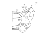
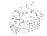
- FIG. 1 is a diagram for explaining a vehicle including an object moving mechanism according to an embodiment of the present invention, and is a schematic view of a rear portion of the vehicle as seen from a side. It is a figure for explaining a vehicle provided with an object moving mechanism concerning one embodiment of the present invention, and is a figure which looked at the back of the vehicle from diagonally upper back. It is a figure for demonstrating the structure of a drive device. It is a figure for demonstrating the structure of a support device. It is a figure for demonstrating the structure of a control mechanism, Comprising: It is the figure seen from the direction of the arrow X in FIG.
- FIG. 6B is a diagram showing a state in which it is rotated to the opposite side with respect to the predetermined side in the direction around the axis.
- the object moving mechanism 1 according to the embodiment of the present invention will be described with reference to FIGS. 1 to 6.
- the direction of arrow A shown in FIGS. 3 and 4 is defined as the advancing direction of the actuating member 12A in the drive device 10 or the advancing direction of the driven member 52A in the supporting device 50. Describe. Further, the direction opposite to the direction of arrow A is described as the backward direction.
- the object moving mechanism 1 in the present embodiment is for converting a rotational movement by driving a driving motor or the like into a rectilinear forward / backward movement and moving the object in a predetermined direction.
- a back door 101 that opens and closes a rear portion of a vehicle 100 is used as a moving object, and the back door 101 is moved (swings) in the vertical direction.
- An opening / closing drive device may be used.
- the moving object is not limited to the back door 101 described above, and may be, for example, an opening / closing body that opens and closes an opening on the side surface of the vehicle, or a window of an automatic opening / closing window in the field of housing. May be That is, the object moving mechanism 1 that embodies the present invention is not limited to the opening / closing drive device that opens and closes the back door 101 as described above.
- the present invention can be applied to a device in which movement of an object is performed by driving with support, such as a device for moving in the left-right direction or an oblique direction.
- the object moving mechanism 1 mainly includes a drive device 10 that moves (swings) the back door 101, and a support device that supports the back door 101 while following the movement operation of the back door 101. 50 and the like.
- each member on the tip side in the lengthwise direction (specifically, an actuating member 12A and a driven member 52A, which will be described later) is configured to be able to move forward and backward. They are arranged on one side surface and the other side surface of the rear portion of vehicle 100, respectively.
- the back door 101 is provided at the upper end portion so as to be movable (swingable) in the vertical direction via a hinge or the like (not shown).
- the drive device 10 is rotatably connected to the back door 101 on one side surface of the rear portion of the vehicle 100 (in the present embodiment, the left side of the paper surface in FIG. 2).
- the drive device 10 is rotatably connected to the body 102 via a second connecting portion 18 of a holding member 12B described later. Further, the drive device 10 is rotatably connected to the back door 101 via the first connecting portion 17 of the actuating member 12A that moves forward and backward relative to the holding member 12B.
- the support device 50 is rotatable with the body 102 via a fourth connecting portion 58 of a holding member 52B described later. Is connected to the back door 101 via the third connecting portion 57 of the driven member 52A that moves forward and backward relative to the holding member 52B.
- the back door 101 is pushed up from below by the operating member 12A and moves (rocks) upward. ) Will be done.
- the driven member 52A of the support member 3 also advances while supporting the back door 101 following this.
- the back door 101 is moved downward (swing) by being pulled downward by the operating member 12A or being lowered by its own weight. Further, when the back door 101 is moved (swinged) downward, the driven member 52A of the support member 3 also moves backward while following the movement of the back door 101 while supporting the back door 101.
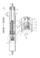
- the drive device 10 includes a drive motor 11 that is an example of a drive unit, an operating member 12A that operates in a forward / backward direction (a direction parallel to the direction of arrow A in FIG. 3) by the drive of the drive motor 11, and an operating member 12A.
- a holding member 12B that constitutes the side housing 12 and a drive device side biasing member 13 that biases the back door 101 (see FIG. 1) that is an example of the moving object are provided.
- the actuating member 12A includes an actuating member-side spindle member 14 that is rotated by the drive of the drive motor 11, a nut member 15 that is screwed into the actuating member-side spindle member 14, and a moving member 16 that is connected to the nut member 15.
- the actuating member 12A is a bottomed cylindrical member whose one end surface is an open surface, and the closed end surface 12A1 is provided with a first connecting portion 17.
- the first connecting portion 17 is, for example, a ball joint, and is rotatably connected to a mounting member (not shown) provided on the back door 101.
- the drive device side housing 12 constituted by the actuating member 12A is provided with the first connecting portion 17 which is connected to the back door 101 which is the moving object.
- the configuration of the first connecting portion 17 is not limited to the configuration directly connected to the back door 101 as shown in the present embodiment, and another mechanism such as a link mechanism is used. It may be configured to be connected to the back door via the.
- the holding member 12B is a bottomed cylindrical member having an open end on one end surface, and its inner diameter is set to be larger than the outer diameter of the actuating member 12A. Further, a second connecting portion 18 is provided on the closed end surface 12B1 of the holding member 12B, and the second connecting portion 18 is, for example, a ball joint like the first connecting portion 17 described above, and the vehicle 100 ( It is rotatably connected to a mounting member (not shown) provided at the rear part (see FIG. 1).
- the configuration of the second connecting portion 18 is not limited to the configuration in which the second connecting portion 18 is directly connected to the rear portion of the vehicle 100 as shown in the present embodiment, and other configurations such as, for example, a link mechanism or the like. It may be configured to be connected to the rear part of the vehicle 100 via a mechanism.
- the actuating member 12A and the holding member 12B are arranged coaxially with each other, and the actuating member 12A is axially movable relative to the holding member 12B inside the holding member 12B.
- the actuating member 12A is arranged with the closed end face 12A1 facing the advancing direction (the direction of arrow A in FIG. 3) and the open end face facing the holding member 12B. It Further, the holding member 12B is arranged in a state in which the closed end surface 12B1 faces the retreat direction side and the end surface which is the open surface faces the actuating member 12A side.
- the end portion 12A2 on the open surface side of the actuating member 12A is inserted into the inside of the holding member 12B via the open surface of the holding member 12B.
- the actuating member 12A is fitted so as to be relatively movable with respect to the holding member 12B.
- the drive unit housing 12 is configured by the actuating member 12A and the holding member 12B having such a configuration.
- the internal space of the holding member 12B includes a closed end surface side space portion 12B3 located on the closed end surface 12B1 side and an open surface side space portion provided on the open surface side by a partition wall portion 12B2 provided in parallel with the closed end surface 12B1. It is separated from 12B4.
- the inner space portion 12A3 of the actuating member 12A is in a state of being communicated with the open surface side space portion 12B4 of the holding member 12B by inserting the end portion 12A2 of the actuating member 12A inside the holding member 12B. ing.
- the space portion 19 defined by the actuating member 12A and the holding member 12B with respect to the outside of the drive device side housing 12 includes the first space portion 19A including the closed end surface side space portion 12B3 and the open surface side space.
- the second space portion 19B includes the portion 12B4 and the inner space portion 12A3.
- the drive motor 11 is arranged in the first space portion 19A of the drive device side housing 12 with the drive shaft 11a facing the operating member 12A side (advancing direction side). That is, the drive motor 11 is provided in the drive device side housing 12 (more specifically, the closed end face side space portion 12B3 of the holding member 12B).
- the drive device side biasing member 13, and the operation member side spindle member 14, the nut member 15, and the moving member 16 included in the operation member 12A. Etc. are arranged, and the hollow cylindrical rotation restricting member 20 that restricts the rotation operation of the nut member 15 is arranged coaxially with the holding member 12B.
- the volume of the second space portion 19B is changed by the movement of the actuating member 12A with respect to the holding member 12B in the advancing / retreating direction. Specifically, the volume of the second space portion 19B is the largest when the operating member 12A is most protruded in the advancing direction side with respect to the holding member 12B. Further, the volume of the second space portion 19B is the smallest when the actuating member 12A is most retracted with respect to the holding member 12B in the backward direction.
- the drive device-side biasing member 13 is composed of an elastic member such as a coil spring, and the outer diameter thereof is set smaller than the inner diameter of the actuating member 12A, while the inner diameter thereof is set to the rotation regulating member 20 or It is set to be sufficiently larger than the outer diameter of the moving member 16.
- the drive device-side biasing member 13 is arranged coaxially with the actuating member 12A (or the holding member 12B) in the second space portion 19B. Further, the drive device side biasing member 13 abuts the closed end surface 12A1 of the actuating member 12A at one end portion (the end portion on the advancing direction side in the present embodiment) of the drive device side biasing member 13 and the other end portion (in this embodiment Is arranged in contact with the partition wall portion 12B2 of the holding member 12B at the end portion on the backward direction side). As a result, the actuating member 12A is always biased by the driving device-side biasing member 13 so as to move toward the advancing direction in the axial direction with respect to the holding member 12B.
- the driving device side biasing member 13 has one end fixed to the closed end face 12A1 of the actuating member 12A and the other end fixed to the partition wall 12B2 of the holding member 12B so as to generate a predetermined biasing force in the axial direction. It may have been done.
- the operating member side spindle member 14 is made of a round bar-shaped member, and the outer peripheral surface thereof is provided with a convex male screw portion 14a spirally formed in the axial direction.
- the operation member side spindle member 14 is arranged in the second space 19B so as to be located coaxially with the drive shaft 11a of the drive motor 11 and inside the drive device side biasing member 13 in the radial direction. Further, the operation member side spindle member 14 is rotatably supported in the axial direction via the bearing member 21 fixed to the partition wall portion 12B2 at the end portion 14b on the backward direction side.
- the operation member side spindle member 14 is connected to the drive shaft 11a of the drive motor 11 via a commercially available shaft coupling 22 at the tip of the end portion 14b. As a result, when electric power is supplied based on a control signal from a control unit (not shown) and the drive motor 11 is driven, the operating member side spindle member 14 is rotated in the axial direction.
- the actuating member side spindle member 14 is not limited to the configuration shown in the present embodiment in which it is directly connected to the drive shaft 11a of the drive motor 11 via the shaft coupling 22, and is driven via, for example, a reduction mechanism. It may be configured to be connected to the drive shaft 11a of the motor 11.
- the nut member 15 is made of a hollow member, and an inner peripheral surface thereof is provided with a female screw portion 15a formed in a spiral shape in the axial direction. Further, the nut member 15 is fixed to a moving member 16 described later at the end portion on the advancing direction side in the axial direction.
- the nut member 15 is arranged coaxially with the operating member side spindle member 14 on the outer peripheral surface of the operating member side spindle member 14, and the male member of the operating member side spindle member 14 is inserted through the female screw portion 15a. It is screwed with the screw portion 14a.
- the actuating member side spindle member 14 is rotated in the axial direction by the driving of the drive motor 11, the nut member 15 is relatively rotated with respect to the actuating member side spindle member 14, and together with the moving member 16, the actuating member side. It moves in the axial direction of the spindle member 14.
- the nut member 15 moves toward the axial advancing direction side of the operating member side spindle member 14.
- the nut member 15 moves toward the axial retracting direction side of the operating member side spindle member 14.
- the rotation restricting member 20 formed of a hollow cylindrical member is provided in the open surface side space 12B4 of the holding member 12B described above.
- the rotation restricting member 20 is arranged on the outer side in the radial direction of the operating member side spindle member 14, coaxially with the operating member side spindle member 14, and on the inner side in the radial direction of the drive device side biasing member 13. Further, the rotation restricting member 20 is fixed to the partition wall portion 12B2 of the holding member 12B at the end portion on the backward direction side.
- a concave portion 20 a extending in the axial direction is formed on the inner peripheral surface of the rotation restricting member 20.
- a convex portion 15b that can be fitted into the concave portion 20a is formed on the outer peripheral surface of the nut member 15.
- the nut member 15 is screwed onto the operating member side spindle member 14, and the convex portion 15b fits into the concave portion 20a of the rotation restricting member 20, while the nut member 15 is engaged with the operating member side with respect to the rotation restricting member 20. It is slidable in the axial direction of the spindle member 14. Thus, the nut member 15 is restricted from rotating in the axial direction with the rotation of the operating member side spindle member 14 in the axial direction, and the nut member 15 is prevented from rotating in the axial direction of the operating member side spindle member 14. The member 15 can be moved reliably.
- the configuration of the rotation restricting member 20 is not limited to the configuration shown in the present embodiment, and for example, on the inner peripheral surface of the rotation restricting member 20, a protrusion extending in the axial direction is formed and a nut member is formed. On the outer peripheral surface of 15, a concave portion that can be fitted with the convex portion may be formed. Further, the nut member 15 is formed in a polygonal cross-section, and the inner peripheral surface of the rotation restricting member 20 is provided with a portion that comes into contact with a part of the outer peripheral surface of the nut member 15. Accordingly, the nut member 15 may be prevented from rotating. That is, regarding the configuration of the rotation restricting member 20, it is only necessary that the rotation of the nut member 15 can be restricted in association with the operating member side spindle member 14 and that the movement of the nut member 15 is not hindered. ..
- the moving member 16 is made of a hollow cylindrical member, and is positioned in the inner space 12A3 of the actuating member 12A coaxially with the actuating member side spindle member 14 and radially inward of the drive device side biasing member 13. Will be placed.
- the moving member 16 is fixed to the closed end surface 12A1 of the actuating member 12A at one end (the end on the advancing direction side), and at the other end (the end on the retreating direction side) the nut member. It is fixed at 15.
- the nut member 15, the moving member 16 and the operating member 12A are integrated and the operating member side spindle member 14 is integrated. It moves to the advancing direction side in the axial direction of. Further, when the operating member side spindle member 14 is rotated to the side opposite to the predetermined side in the axial direction, the nut member 15, the moving member 16 and the operating member 12A are integrated to form the operating member side spindle member. It moves to the backward direction side of the axial direction of 14.
- the drive device side biasing member 13 is provided in the second space portion 19B of the drive device side housing 12, and the actuating member 12A is always driven by the drive device side biasing member 13.
- the holding member 12B is biased toward the advancing direction side of the operating member side spindle member 14 in the axial direction.
- the biasing force applied to the actuating member 12A by the driving device-side biasing member 13 is transmitted to the nut member 15 via the moving member 16. Therefore, the nut member 15 is always urged by the drive device side urging member 13 toward the holding member 12B toward the advancing direction side of the operating member side spindle member 14 in the axial direction. ..
- Such a structure not only reduces the driving force of the drive motor 11 by the driving device side biasing member 13, but also reduces the driving force of the driving motor 11 from the male screw portion 14a of the operating member side spindle member 14 and the female screw portion 15b of the nut member 15. It is possible to reduce rattling that occurs between the drive motor 11 and the drive of the drive motor 11 to the nut member 15 more efficiently via the operating member side spindle member 14.
- the drive member side biasing member 13 constantly biases the actuating member 12A toward the axial advancing direction side of the actuating member side spindle member 14, such a lock is performed.
- the force that tries to rotate the drive shaft 11a against the above-described state can be suppressed, and the load applied to the drive motor 11 can be reduced.
- the actuating member 12A by moving the actuating member 12A toward the advancing direction side of the holding member 12B in the axial direction of the actuating member side spindle member 14, the actuating member 12A is moved. It is a mechanism for moving (swinging) the back door 101 (see FIG. 1) upward.
- the load of the back door 101 due to its own weight can be reduced by the biasing force of the driving device side biasing member 13, and the driving force required for the drive motor 11 can be set smaller.
- the support device 50 has substantially the same structure as the drive device 10 described above, but is not provided with a drive mechanism including the drive motor 11 and the shaft coupling 22 (see FIG. 3), and is provided with the regulation mechanism 70. This is different from the drive device 10 in that. Therefore, in the following description, mainly the differences from the driving device 10 described above will be described, and the description of the configuration equivalent to the driving device 10 will be omitted.
- the support device 50 includes a connection part (more specifically, a connection part) that is connected to the actuation member 12A (see FIG. 3) of the drive device 10 via the back door 101 (see FIG. 1) that is a moving object.
- the third connecting portion 57) the driven member 52A that follows the operation of the actuating member 12A, the holding member 52B that constitutes the supporting device side housing 52 together with the driven member 52A, and the supporting device side that urges the driven member 52A.
- the biasing member 53 and the regulation mechanism 70 for restraining or allowing the movement of the driven member 52A are provided.
- the driven member 52A includes a driven member-side spindle member 54 that is rotatable about the axis, a nut member 55 that is screwed into the driven member-side spindle member 54, and a moving member 56 that is connected to the nut member 55.
- the third connecting portion 57, the driven member 52A, the supporting device side housing 52, the holding member 52B, the supporting device side biasing member 53, the driven member side spindle member 54, the nut member 55, and the moving member 56 are the same as those described above.
- the driven member 52A is provided with a third connecting portion 57, and the third connecting portion 57 is rotatably connected to a mounting member (not shown) provided on the back door 101.
- the support device side housing 52 configured by the driven member 52A is provided with the third connecting portion 57 that is connected to the back door 101 that is the moving object.
- the configuration of the third connection portion 57 is not limited to the configuration directly connected to the back door 101 as shown in the present embodiment, and another mechanism such as a link mechanism is used. It may be configured to be connected to the back door via the.
- the holding member 52B is provided with a fourth connecting portion 58, and the fourth connecting portion 58 is rotatable with respect to a mounting member (not shown) provided at a rear portion of the vehicle 100 (see FIG. 1). Connected.
- the configuration of the fourth connection portion 58 is not limited to the configuration directly connected to the rear portion of the vehicle 100 as shown in the present embodiment, and other configurations such as a link mechanism or the like may be used. It may be configured to be connected to the rear part of the vehicle 100 via a mechanism.
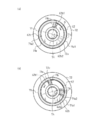
- the driven member-side spindle member 54 is provided with the driven member-side spindle member 54 and a rotating member 62 that rotates in the direction around the axis of the driven member-side spindle member 54.
- the rotating member 62 is made of a hollow cylindrical member, and has a shape conforming to the end 54b of the driven member side spindle member 54 on one end side (in this embodiment, the end side on the advancing direction side).
- the through hole 62a is provided coaxially.
- a plurality of convex portions 54b1 (see FIG. 5) extending in the axial direction of the driven member side spindle member 54 are formed on the outer peripheral surface of the tip end portion of the end portion 54b of the driven member side spindle member 54. ..
- a plurality of concave portions 62a1 (see FIG. 5) extending in the axial direction of the rotating member 62 and capable of being fitted with the plurality of convex portions 54b1 are formed. Has been done.
- the rotating member 62 has the concave portion 62a1 of the through hole 62a and the convex portion 54b1 of the end portion 54b. In the fitted state, relative rotation is suppressed with respect to the driven member side spindle member 54.
- the first groove portion 62b1 is formed so as to extend toward the inner side in the radial direction of the rotating member 62 at the other end side (rearward direction side in the present embodiment) of the rotating member 62. Further, the second groove portion 62b2 faces the inner side in the radial direction of the rotating member 62 at a position slightly separated from the first groove portion 62b1 on the side of the through hole 62a (in the present embodiment, the advancing direction side). Is formed so as to extend. Further, as shown in FIG. 5, the first groove portion 62b1 and the second groove portion 62b2 are provided at different angular positions in the axial direction of the rotating member 62.
- the inner volumes of the first groove portion 62b1 and the second groove portion 62b2 are set to be slightly larger than the first arm portion 71b and the second arm portion 71c of the brake spring 71 so as to form a gap,
- the rotating member 62 is configured to be capable of slightly rotating relative to the brake spring 71 in the direction around the axis of the rotating member 62.
- the regulation mechanism 70 is mainly composed of a brake spring 71, an outer member 72, and the like.
- the brake spring 71 is composed of a so-called torsion coil spring, and as shown in FIG. 4, a body portion 71a formed of a portion in which a wire is closely wound, and both ends of the body portion 71a in a radial direction of the body portion 71a. It is configured by a first arm portion 71b and a second arm portion 71c that extend inward.
- the brake spring 71 increases or decreases the frictional force with respect to the rotating member 62 by increasing (increasing the diameter) or reducing (reducing the diameter) the inner diameter of the body portion 71a, thereby generating the braking force. It is configured to let.
- the inner diameter of the body portion 71a is set to be slightly larger than the outer diameter of the rotating member 62. Further, the outer diameter of the body portion 71a is set to be substantially equal to the outer diameter of the outer member 72 described later.
- the brake spring 71 arranges the body portion 71a coaxially with the rotating member 62 on the outer side in the radial direction of the rotating member 62, and at the same time, the first arm portion 71b and the second arm portion 71c. Are inserted in the first groove portion 62b1 and the second groove portion 62b2 of the rotating member 62, respectively. That is, the brake spring 71 is fitted to the outside (radially outside) of the rotating member 62 via the first arm portion 71b and the second arm portion 71c.
- the outer member 72 is made of a hollow cylindrical member, and its inner diameter is larger than the outer diameter of the rotating member 62 and substantially larger than the outer diameter of the body portion 71 a of the brake spring 71. It is set equally.
- the outer member 72 is arranged coaxially with the rotating member 62 on the outer side in the radial direction of the rotating member 62, and is fixed by a holding member 52B so as not to be rotatable in the axial direction.
- the brake spring 71 arranged on the rotating member 62 has the outer peripheral surface 71a1 of the body 71a in close contact with the inner peripheral surface 72a of the outer member 72. Is fitted inside.
- an outer member 72 that is connected to the support member side housing (more specifically, the holding member 52B) is provided on the outer side of the brake spring 71 (the outer side in the radial direction of the body portion 71a).
- the brake spring 71 is temporarily held in a state in which relative rotation in the axial direction with respect to the driven member side spindle member 54 is temporarily disabled by friction with the outer member 72.
- the urging force of the drive device side urging member 13 and the support device side urging member 53, and the drive of the drive device 10 are not added to the driven member 12A, and the driven member side
- a gap is formed between the inner peripheral surface 71a2 of the body portion 71a and the outer peripheral surface 62b of the rotating member 62.
- the inner peripheral surface 71a2 of the body portion 71a of the brake spring 71 is not in close contact with the outer peripheral surface 62b of the rotating member 62).
- the rotating member 62 is driven by the spindle member on the driven member side within a range in which the first arm portion 71b or the second arm portion 71c of the brake spring 71 does not contact the inner side surfaces of the first groove portion 62b1 or the second groove portion 62b2, respectively. Together with 54, it is in a state of being slightly rotatable in the direction around the axis.
- the relative movement of the driven member 52A with respect to the holding member 52B is allowed or restricted by the restricting mechanism 70 having the above-described configuration depending on the situation in which the operation is performed.
- the actuating member 12A of the driving device 10 and the driven member 52A of the supporting device 50 mainly apply the biasing force of the driving device-side biasing member 13, and Only the urging force of the supporting device side urging member 53 is applied.
- the biasing force transmitted to the driven member 52A is transmitted to the driven member side spindle member 54 via the nut member 55 (see FIG. 4).
- the driven member side spindle member 54 is rotated together with the rotating member 62 to a predetermined side in the axial direction (for example, the side of the arrow B in FIG. 6A).
- both the first groove portion 62b1 and the second groove portion 62b2 move to the predetermined side in the axial direction. Then, only the inner side surface of the first groove portion 62b1 immediately contacts the first arm portion 71b of the brake spring 71.
- the first arm portion 71b engages with the first groove portion 62b1 and is moved together with the rotating member 62 to the predetermined side in the axial direction (the side of the arrow B).
- the rotating member 62 stops in a state where the urging force transmitted to the driven member side spindle member 54 (rotating member 62) via the driven member 52A and the elastic force of the brake spring 71 are in balance.
- the body portion 71a of the brake spring 71 has the inner diameter reduced only in the region on the first arm portion 71b side (hereinafter, referred to as "first region"), and the inner peripheral surface 71a2 of the first region is reduced.
- first region the region on the first arm portion 71b side
- second region the region of the body portion 71a on the second arm portion 71c side
- the brake spring 71 restrains the relative rotation in the axial direction with respect to the rotating member 62 due to friction with the rotating member 62 in the first region (the region on the side of the first arm 71b) of the body 71a. Further, in the second region of the body portion 71a (region on the second arm portion 71c side), relative to the outer member 72 in the axial direction is restrained by friction with the outer member 72. That is, the rotation member 62 is restrained from rotating with respect to the outer member 72 to the predetermined side in the axial direction (direction of the arrow B) via the brake spring 71.
- the driven member 52A moves relatively to the holding member 52B by the urging force of the drive device side urging member 13 and the urging force of the support member side urging member 53. Are restrained by the regulation mechanism 70.
- both the first groove portion 62b1 and the second groove portion 62b2 move to the side opposite to the predetermined side in the axial direction. Moving. Then, the first groove portion 62b1 is released from the engaged state with the first arm portion 71b of the brake spring 71, and only the inner surface of the second groove portion 62b2 immediately contacts the second arm portion 72c of the brake spring 71. Contact.
- the second arm portion 71c engages with the second groove portion 62b2, and the side opposite to the predetermined side in the axial direction together with the rotating member 62 (the direction of the arrow C). ),
- the rotation member 62 stops in a state where the external force transmitted to the driven member side spindle member 54 (rotation member 62) via the driven member 52A and the elastic force of the brake spring 71 are in balance. To do.
- the body 71a of the brake spring 71 has a reduced inner diameter only in the above-described second region (region on the side of the second arm 71c), and the inner peripheral surface 71a2 of the second region is connected to the rotating member 62.
- the outer peripheral surface 62b is brought into close contact with the outer peripheral surface 62b.
- the inner diameter is restored, and the outer peripheral surface 71a is brought into close contact with the inner peripheral surface 72a of the outer member 72.
- the driven member 52A mainly includes the drive device side biasing member 13. And the urging force of the supporting device side urging member 53 are respectively applied. Therefore, as shown in FIG. 6A, the rotation member 62 temporarily restrains the rotation of the rotation member 62 with respect to the outer member 72 to the predetermined side (the direction of the arrow B) in the axial direction with respect to the outer member 72. It is in the state of being
- the driving force of the drive motor 11 transmitted to the driven member 52A is transmitted to the driven member-side spindle member 54 via the nut member 55 (see FIG. 4).
- the driving force of the drive motor 11 is generated between the outer peripheral surface 71a1 of the second area (area on the second arm portion 71c side) of the body portion 71a of the brake spring 71 and the inner peripheral surface 72a of the outer member 72. Since the frictional force is greatly exceeded, the driven member side spindle member 54 is further rotated together with the rotating member 62 toward the predetermined side in the axial direction (the side indicated by the arrow B).
- the rotating member 62 slides on the inner peripheral surface 72a of the outer member 72 via the second region (the region on the side of the second arm 71c), and while rotating, a predetermined side in the axial direction (arrow B). It is further rotated toward the direction side).
- the first arm portion 71b of the brake spring 71 is moved to the predetermined side in the axial direction (the side of the arrow B) together with the rotating member 62 while engaging with the first groove portion 62b1.
- the body portion 71a of 71 has a reduced inner diameter in the entire region including the first region and the second region, and the inner peripheral surface 71a2 is in close contact with the outer peripheral surface 62b of the rotating member 62.
- the outer diameter of the body portion 71a of the brake spring 71 is reduced, and the outer peripheral surface 71a1 of the body portion 71a and the inner peripheral surface 72a of the outer member 72 are released from being in close contact with each other.
- the driven member 52A mainly includes the drive device. Only the biasing force of the side biasing member 13 and the biasing force of the supporting device side biasing member 53 are added respectively. Therefore, as shown in FIG. 6A, the rotation member 62 temporarily restrains the rotation of the rotation member 62 with respect to the outer member 72 to the predetermined side (the direction of the arrow B) in the axial direction with respect to the outer member 72. It is in the state of being
- the driving force of the drive motor 11 transmitted to the driven member 52A is transmitted to the driven member-side spindle member 54 via the nut member 55 (see FIG. 4).
- the driven member side spindle member 54 is rotated together with the rotating member 62 to the side opposite to the predetermined side in the axial direction (direction of arrow C).
- both the first groove portion 62b1 and the second groove portion 62b2 move to the side opposite to the predetermined side in the axial direction. Moving. Then, the first groove portion 62b1 is released from the engaged state with the first arm portion 71b of the brake spring 71, and only the inner surface of the second groove portion 62b2 immediately contacts the second arm portion 72c of the brake spring 71. Contact.
- the second arm portion 71c engages with the second groove portion 62b2, and the side opposite to the predetermined side in the axial direction together with the rotating member 62 (direction of arrow C). Is moved to.
- the brake spring 71 is temporarily restrained from rotating relative to the rotary member 62 in the second region of the body portion 71a due to friction between the brake member 71 and the body portion 71a.
- the relative rotation in the axial direction with respect to the outer member 72 is restricted by the friction with the outer member 72.
- the rotation member 62 is in a state in which the rotation of the outer member 72, which is opposite to the predetermined side in the axial direction (the direction of the arrow C), with respect to the outer member 72 is temporarily restrained via the brake spring 71. ..
- the driving force of the drive motor 11 is generated between the outer peripheral surface 71a1 of the first area (area on the first arm portion 71b side) of the body portion 71a of the brake spring 71 and the inner peripheral surface 72a of the outer member 72. Since the frictional force is greatly exceeded, the driven member-side spindle member 54 is further rotated together with the rotating member 62 toward the side opposite to the predetermined side in the axial direction (direction of arrow C). At this time, the rotating member 62 slides on the inner peripheral surface 72a of the outer member 72 via the first area (area on the side of the first arm portion 71b) while being opposite to the predetermined side in the axial direction. Further rotation is performed toward (direction of arrow C).
- the second arm portion 71c of the brake spring 71 moves to the side opposite to the predetermined side in the axial direction (the direction of the arrow C) together with the rotating member 62 while engaging with the second groove portion 62b2.
- the inner diameter of the body portion 71a of the brake spring 71 is reduced in the entire region including the first region and the second region, and the inner peripheral surface 71a2 is brought into close contact with the outer peripheral surface 62b of the rotating member 62. ..
- the outer diameter of the body portion 71a of the brake spring 71 is reduced, and the outer peripheral surface 71a1 of the body portion 71a and the inner peripheral surface 72a of the outer member 72 are released from being in close contact with each other. Is rotatable relative to the outer member 72 on the side opposite to the predetermined side in the direction around the axis (direction of arrow C).
- the driven member 52A is movable with respect to the holding member 52B toward the advancing direction side or the retreating direction side in the axial direction, and the regulation mechanism 70 is driven.
- the actuating force of the actuating member 12A by the device 10 allows the follower member 52A to follow the actuating member 12A.
- the outer member 72 has the brake spring 71 (in the present embodiment, the trunk portion in the present embodiment) when the drive of the drive device 10 is stopped with respect to the rotating member 62.
- the rotation of the brake spring 71 is suppressed by friction with the outer peripheral surface 71a1 of 71a, and when the drive device 10 is driven, the diameter of the brake spring 71 (in the present embodiment, by the rotation of the rotating member 62).
- the outer diameter of the body portion 71a is reduced so that the brake spring 71 is allowed to rotate.
- the configuration of the regulation mechanism 70 is not limited to the configuration shown in this embodiment. That is, in the regulation mechanism 70 in the present embodiment, the rotation of the brake spring 71 is regulated by friction with the outer member 72 at least until the diameter of the body portion 71a is reduced by the rotation of the rotation member 62. It is in a state of being Then, for example, when the rotating member 62 slightly rotates in the opposite direction to release the brake spring 71 from the force that reduces the diameter of the body portion 71a, the brake spring 71 is immediately restored and the body portion 71a is expanded in diameter.
- the brake spring 71 is configured such that the rotation thereof is restricted by the frictional force with the rotating member 62, while the diameter expansion and the diameter reduction of the body portion 71a are repeated. Therefore, in the brake spring 71, it is important to maintain the frictional force between the brake spring 71 and the rotating member 62 so as not to decrease for a long period of time. It is also important to prevent abnormal noise and the like from being generated between the rotary member 62 and the rotary member 62.
- the diameter of the body portion 71a is reduced as in the present embodiment, so that the regulation member 70 is in close contact with the outer peripheral surface 62b of the rotating member 62. Then, instead of suppressing the rotation of the rotating member 62, the diameter of the body portion 71a is expanded, so that the outer peripheral member 72 is brought into close contact with the inner peripheral surface 72a and the rotation of the rotating member 62 is suppressed. It may be configured to be.
- the object moving mechanism 1 in the present embodiment includes the support device 50 that supports the back door 101, which is an example of the moving object, and the drive device 10 that moves the back door (moving object) 101. It is an object moving mechanism.
- the drive device 10 urges a drive motor 11 that is an example of a drive unit, an actuating member 12A that operates in the forward / backward direction by the drive of the drive motor (drive unit) 11, and a back door (moving target) 101. And a driving device side biasing member 13 for driving.
- the support device 50 includes a connecting portion (more specifically, the third connecting portion 57) that is connected to the operating member 12A via the back door 101, a driven member 52A that is driven by the operation of the operating member 12A, and a driven member.
- the support device-side biasing member 53 that biases the member 52A and the restricting mechanism 70 that restricts or permits the movement of the driven member 52A are provided.
- the regulation mechanism 70 allows the driven member 52A to be driven by the actuating force of the actuating member 12A driven by the driving device 10, and is caused by the movement of the actuating member 12A by the biasing force of the supporting device side biasing member 53. It is configured to restrain the driven member 52A from being driven.
- the regulation mechanism 70 is configured to include a brake spring 71 that generates a braking force by increasing or decreasing the frictional force due to the diameter expansion and the diameter reduction.
- the braking mechanism 70 can be configured more compactly than when a braking device (brake mechanism) having a complicated mechanism is separately provided.
- the drive device 10 includes the drive device side housing 12 provided with the connection portion (more specifically, the first connection portion 17) connected to the back door (moving target) 101.
- the drive motor (drive unit) 11 is provided in the drive device side housing 12, and the operation member 12A includes an operation member side spindle member 14 that is rotated by the drive of the drive motor (drive unit) 11 and an operation member side spindle member 14. It has a nut member 15 that is screwed with and a moving member 16 that is connected to the nut member 15.
- the supporting device 50 has a supporting device side housing 52 provided with a connecting portion (more specifically, a third connecting portion 57) for connecting to the back door (moving object) 101, and the driven member 52A is It has a rotatable driven member side spindle member 54, a nut member 55 screwed to the driven member side spindle member 54, and a moving member 56 connected to the nut member 55.
- the driven member side spindle member 54 is provided with a rotating member 62 that rotates together with the driven member side spindle member 54, and the brake spring 71 is fitted on the outer side of the rotating member 62, and on the outer side of the brake spring 71, An outer member 72 that is connected to the support member housing 52 is provided.
- the outer member 72 suppresses rotation of the brake spring 71 with respect to the rotating member 62 by friction with the brake spring 71 when the drive device 10 is not driven, and when the drive device 10 is driven.
- the diameter of the brake spring 71 is reduced by the rotation of the rotating member 62, and the brake spring 71 is provided at a position where the rotation of the brake spring 71 is allowed.
- the regulation mechanism 70 By configuring the regulation mechanism 70 with the outer member 72 having such a configuration, for example, it is not necessary to separately provide a complicated control program to electrically control, and the drive device 10 can be configured by only a simpler mechanical mechanism. And the operation of the support device 50 can be controlled.
Abstract
バックドアを支持する支持装置とバックドアを移動させる駆動装置を備えた対象物移動機構であって、駆動装置は、駆動モータと、駆動モータの駆動により進退方向に作動する作動部材と、バックドアを付勢する駆動装置側付勢部材とを備え、支持装置は、作動部材に接続する第三接続部と、作動部材の作動に従動する従動部材と、従動部材を付勢する支持装置側付勢部材と、従動部材の移動を拘束又は許容する規制機構とを備え、規制機構は、駆動装置の駆動による作動部材の作動力によって生じる従動部材の従動を許容し、支持装置側付勢部材の付勢力による作動部材の移動によって生じる従動部材の従動を拘束する対象物移動機構を用いることで、駆動装置と支持装置との組合せによって移動対象物を移動させる際に、駆動装置の駆動を止めた場合であっても対象物の移動を抑制できる。
Description
本発明は、対象物移動機構の技術に関する。
車両のドア等の対象物を移動させる対象物移動機構は、駆動部の駆動により対象物を移動させる。移動中の対象物は、姿勢が変化しないように、複数の対象物移動装置を対象物に接続して移動させる方が好ましいが、モータを複数用いるためにコストが高くなり、重量も増加する問題が生じる。
このような問題を解決するために、例えば特許文献1に記載のように、駆動装置である駆動スピンドルと、支持装置であるアシストスプリングとを用いたパワードアが提案されている。
このような問題を解決するために、例えば特許文献1に記載のように、駆動装置である駆動スピンドルと、支持装置であるアシストスプリングとを用いたパワードアが提案されている。
しかし、このような装置では、駆動装置が1つであるために、ドアの種類や取付け方によっては、ドアを全開位置や全閉と全開との途中位置で維持することができない場合があり、移動対象物についての作業時には安全確保のための注意が必要となる。
本発明は、以上に示した現状の問題点に鑑みてなされたものであり、駆動装置と支持装置との組合せによって移動対象物を移動させる際に、駆動装置の駆動を止めた場合であっても対象物の移動を抑制できる対象物移動機構を提供することを課題とする。
本発明の解決しようとする課題は以上の如くであり、次にこの課題を解決するための手段を説明する。
即ち、本発明に係る対象物移動機構は、移動対象物を支持する支持装置と前記移動対象物を移動させる駆動装置とを備えた対象物移動機構であって、前記駆動装置は、駆動部と、前記駆動部の駆動により進退方向に作動する作動部材と、前記移動対象物を付勢する駆動装置側付勢部材とを備え、前記支持装置は、前記作動部材に接続する接続部と、前記作動部材の作動に従動する従動部材と、前記従動部材を付勢する支持装置側付勢部材と、前記従動部材の移動を拘束又は許容する規制機構とを備え、前記規制機構は、前記駆動装置の駆動による前記作動部材の作動力によって生じる前記従動部材の従動を許容し、前記支持装置側付勢部材の付勢力による前記作動部材の移動によって生じる前記従動部材の従動を拘束することを特徴とする。
本発明の効果として、以下に示すような効果を奏する。
即ち、本発明に係る対象物移動機構によれば、駆動装置と支持装置との組合せによって移動対象物を移動させる際に、駆動装置の駆動を止めた場合であっても対象物の移動を抑制できる。
即ち、本発明に係る対象物移動機構によれば、駆動装置と支持装置との組合せによって移動対象物を移動させる際に、駆動装置の駆動を止めた場合であっても対象物の移動を抑制できる。
次に、本発明の一実施形態に係る対象物移動機構1について、図1乃至図6を用いて説明する。
なお、以下の説明に関しては便宜上、図3及び図4中に示した矢印Aの方向を、駆動装置10における作動部材12Aの進出方向、又は支持装置50における従動部材52Aの進出方向と規定して記述する。また、矢印Aの方向とは反対の方向は、後退方向として記述する。
なお、以下の説明に関しては便宜上、図3及び図4中に示した矢印Aの方向を、駆動装置10における作動部材12Aの進出方向、又は支持装置50における従動部材52Aの進出方向と規定して記述する。また、矢印Aの方向とは反対の方向は、後退方向として記述する。
[対象物移動機構1の全体構成]
先ず、対象物移動機構1の全体構成について、図1及び図2を用いて説明する。
本実施形態における対象物移動機構1は、例えば駆動モータなどの駆動による回転運動を直線方向の進退運動に変換し、対象物を所定方向に移動させるものである。
このような対象物移動機構1の一例として、例えば図1に示すような、車両100の後部を開閉するバックドア101を移動対象物とし、当該バックドア101を上下方向に移動(揺動)させる開閉駆動装置が挙げられる。
先ず、対象物移動機構1の全体構成について、図1及び図2を用いて説明する。
本実施形態における対象物移動機構1は、例えば駆動モータなどの駆動による回転運動を直線方向の進退運動に変換し、対象物を所定方向に移動させるものである。
このような対象物移動機構1の一例として、例えば図1に示すような、車両100の後部を開閉するバックドア101を移動対象物とし、当該バックドア101を上下方向に移動(揺動)させる開閉駆動装置が挙げられる。
なお、移動対象物としては、上述のバックドア101に限定されるものではなく、例えば、車両側面の開口を開閉する開閉体であってもよく、また住設分野での自動開閉窓の窓などであってもよい。
即ち、本発明を具現化する対象物移動機構1は、上述したような、バックドア101を開閉させる開閉駆動装置に限定されるものではなく、移動対象物である物品又は構造を、上下方向、左右方向、又は斜め方向に移動させる装置など、対象物の移動が支持を伴う駆動により行われる装置に適用することが可能である。
即ち、本発明を具現化する対象物移動機構1は、上述したような、バックドア101を開閉させる開閉駆動装置に限定されるものではなく、移動対象物である物品又は構造を、上下方向、左右方向、又は斜め方向に移動させる装置など、対象物の移動が支持を伴う駆動により行われる装置に適用することが可能である。
対象物移動機構1は、図2に示すように、主にバックドア101を移動(揺動)させる駆動装置10、及びバックドア101の移動動作に追従しながら当該バックドア101を支持する支持装置50などを備える。
駆動装置10及び支持装置50は、詳細は後述するが、各々長さ方向に先端側の部材(具体的には、後述する作動部材12A、及び従動部材52A)が進退可能に構成されており、車両100後部の一方の側面、及び他方の側面にそれぞれ配置される。
具体的には、車両100のボディ102に対して、バックドア101は、上端部においてヒンジ等(図示せず)を介して上下方向に移動(揺動)可能に設けられている。
そして、車両100後部の一方(本実施形態においては、図2における紙面左側)の側面において、駆動装置10は、バックドア101と回動可能に連結される。駆動装置10は、後述する保持部材12Bの第二接続部18を介して、ボディ102と回動可能に連結される。また、駆動装置10は、保持部材12Bに対して相対的に進退する作動部材12Aの第一接続部17を介して、バックドア101と回動可能に連結される。
また、車両100後部の他方(本実施形態においては、図2における紙面右側)の側面において、支持装置50は、後述する保持部材52Bの第四接続部58を介して、ボディ102と回動可能に連結され、且つ保持部材52Bに対して相対的に進退する従動部材52Aの第三接続部57を介して、バックドア101と回動可能に連結される。
このような構成からなる対象物移動機構1において、例えば、駆動装置10の作動部材12Aが進出することにより、バックドア101は、当該作動部材12Aによって下方から押し上げられて、上方に移動(揺動)される。
また、バックドア101が上方に移動(揺動)されると、支持部材3の従動部材52Aも、これに追従してバックドア101を支持しながら進出される。
また、バックドア101が上方に移動(揺動)されると、支持部材3の従動部材52Aも、これに追従してバックドア101を支持しながら進出される。
一方、駆動装置10の作動部材12Aが後退すると、バックドア101は、当該作動部材12Aによって下方に引き寄せられるか自重によって降下することで、下方に移動(揺動)される。
また、バックドア101が下方に移動(揺動)されると、支持部材3の従動部材52Aも、バックドア101の動きに追従してバックドア101を支持しながら後退される。
また、バックドア101が下方に移動(揺動)されると、支持部材3の従動部材52Aも、バックドア101の動きに追従してバックドア101を支持しながら後退される。
[駆動装置10の構成]
次に、駆動装置10の構成について、図3を用いて説明する。
駆動装置10は、駆動部の一例である駆動モータ11、駆動モータ11の駆動により進退方向(図3中の矢印Aの方向との平行方向)に作動する作動部材12A、作動部材12Aとともに駆動装置側ハウジング12を構成する保持部材12B、及び移動対象物の一例であるバックドア101(図1を参照)を付勢する駆動装置側付勢部材13などを備える。
また、作動部材12Aは、駆動モータ11の駆動により回転する作動部材側スピンドル部材14、作動部材側スピンドル部材14と螺合するナット部材15、及びナット部材15と連結した移動部材16などを有する。
次に、駆動装置10の構成について、図3を用いて説明する。
駆動装置10は、駆動部の一例である駆動モータ11、駆動モータ11の駆動により進退方向(図3中の矢印Aの方向との平行方向)に作動する作動部材12A、作動部材12Aとともに駆動装置側ハウジング12を構成する保持部材12B、及び移動対象物の一例であるバックドア101(図1を参照)を付勢する駆動装置側付勢部材13などを備える。
また、作動部材12Aは、駆動モータ11の駆動により回転する作動部材側スピンドル部材14、作動部材側スピンドル部材14と螺合するナット部材15、及びナット部材15と連結した移動部材16などを有する。
作動部材12Aは、一方の端面が開放面となった有底円筒形状の部材からなり、その閉鎖端面12A1には、第一接続部17が設けられている。
第一接続部17は、例えばボールジョイントであり、バックドア101に設けられた取付部材(図示せず)と回動可能に接続される。
換言すると、作動部材12Aによって構成される駆動装置側ハウジング12には、移動対象物であるバックドア101に接続する第一接続部17が設けられる。
第一接続部17は、例えばボールジョイントであり、バックドア101に設けられた取付部材(図示せず)と回動可能に接続される。
換言すると、作動部材12Aによって構成される駆動装置側ハウジング12には、移動対象物であるバックドア101に接続する第一接続部17が設けられる。
なお、第一接続部17の構成については、本実施形態に示されるような、バックドア101と直接的に連結される構成に限定されるものではなく、例えばリンク機構等のような他の機構を介して、バックドアと連結される構成であってもよい。
保持部材12Bは、一方の端面が開放面となった有底円筒形状の部材からなり、その内径は、作動部材12Aの外径に比べて大きく設定されている。
また、保持部材12Bの閉鎖端面12B1には、第二接続部18が設けられており、当該第二接続部18は、上述の第一接続部17と同様、例えばボールジョイントであり、車両100(図1を参照)の後部に設けられた取付部材(図示せず)と回動可能に接続される。
また、保持部材12Bの閉鎖端面12B1には、第二接続部18が設けられており、当該第二接続部18は、上述の第一接続部17と同様、例えばボールジョイントであり、車両100(図1を参照)の後部に設けられた取付部材(図示せず)と回動可能に接続される。
なお、第二接続部18の構成についても、本実施形態に示されるような、車両100の後部と直接的に連結される構成に限定されるものではなく、例えばリンク機構等のような他の機構を介して、車両100の後部と連結される構成であってもよい。
そして、これらの作動部材12A及び保持部材12Bは、ともに同軸上に配置され、保持部材12Bの内側において、作動部材12Aが当該保持部材12Bに対して軸方向に相対移動可能に構成されている。
具体的には、作動部材12Aは、閉鎖端面12A1を進出方向(図3中の矢印Aの方向)側に向け、且つ開放面となった端面を保持部材12B側に向けた状態にて配置される。
また、保持部材12Bは、閉鎖端面12B1を後退方向側に向け、且つ開放面となった端面を作動部材12A側に向けた状態にて配置される。
また、保持部材12Bは、閉鎖端面12B1を後退方向側に向け、且つ開放面となった端面を作動部材12A側に向けた状態にて配置される。
そして、保持部材12Bの開放面を介して、作動部材12Aの開放面側の端部12A2が保持部材12Bの内側に挿入されている。作動部材12Aは、保持部材12Bに対して相対移動可能に嵌合される。
このような構成からなる作動部材12A及び保持部材12Bによって、駆動装置側ハウジング12が構成される。
ここで、保持部材12Bの内部空間は、閉鎖端面12B1と平行に設けられる隔壁部12B2によって、閉鎖端面12B1側に位置する閉鎖端面側空間部12B3と、開放面側に設けられる開放面側空間部12B4とに隔絶されている。
また、作動部材12Aの内側空間部12A3は、当該作動部材12Aの端部12A2が保持部材12Bの内側に挿入されることにより、保持部材12Bの開放面側空間部12B4と連通された状態となっている。
ここで、保持部材12Bの内部空間は、閉鎖端面12B1と平行に設けられる隔壁部12B2によって、閉鎖端面12B1側に位置する閉鎖端面側空間部12B3と、開放面側に設けられる開放面側空間部12B4とに隔絶されている。
また、作動部材12Aの内側空間部12A3は、当該作動部材12Aの端部12A2が保持部材12Bの内側に挿入されることにより、保持部材12Bの開放面側空間部12B4と連通された状態となっている。
このように、作動部材12A及び保持部材12Bによって、駆動装置側ハウジング12の外部に対して画定される空間部19は、閉鎖端面側空間部12B3からなる第一空間部19A、並びに開放面側空間部12B4及び内側空間部12A3からなる第二空間部19Bによって構成される。
そして、駆動装置側ハウジング12の第一空間部19Aには、駆動モータ11が、作動部材12A側(進出方向側)に駆動軸11aを向けた状態にて配置される。
つまり、駆動モータ11は、駆動装置側ハウジング12(より具体的には、保持部材12Bの閉鎖端面側空間部12B3)に設けられる。
つまり、駆動モータ11は、駆動装置側ハウジング12(より具体的には、保持部材12Bの閉鎖端面側空間部12B3)に設けられる。
また、駆動装置側ハウジング12の第二空間部19Bには、後述するように、駆動装置側付勢部材13、並びに作動部材12Aが有する作動部材側スピンドル部材14、ナット部材15、及び移動部材16などが配置されるとともに、ナット部材15の回転動作を規制する中空円筒形状の回転規制部材20が、保持部材12Bと同軸上に配置される。
なお、第二空間部19Bは、保持部材12Bに対する作動部材12Aの進退方向への移動によって、体積が変更される。
具体的には、作動部材12Aが保持部材12Bに対して進出方向側に最も突出した状態において、第二空間部19Bの体積は最も大きくなる。また、作動部材12Aが保持部材12Bに対して後退方向側に最も引き込まれた状態において、第二空間部19Bの体積は最も小さくなる。
具体的には、作動部材12Aが保持部材12Bに対して進出方向側に最も突出した状態において、第二空間部19Bの体積は最も大きくなる。また、作動部材12Aが保持部材12Bに対して後退方向側に最も引き込まれた状態において、第二空間部19Bの体積は最も小さくなる。
駆動装置側付勢部材13は、例えばコイルスプリングからなる弾性部材によって構成されており、その外径は、作動部材12Aの内径に比べて小さく設定される一方、その内径は、回転規制部材20や移動部材16の外径に比べて十分大きく設定されている。
そして、駆動装置側付勢部材13は、第二空間部19Bにおいて、作動部材12A(または、保持部材12B)と同軸上に配置される。
また、駆動装置側付勢部材13は、その一端部(本実施形態においては、進出方向側の端部)において、作動部材12Aの閉鎖端面12A1と当接し、且つその他端部(本実施形態においては、後退方向側の端部)において、保持部材12Bの隔壁部12B2と当接した状態にて配置される。
これにより、作動部材12Aは、駆動装置側付勢部材13によって、保持部材12Bに対して軸方向の進出方向側へと移動するように、常に付勢された状態となっている。
また、駆動装置側付勢部材13は、その一端部(本実施形態においては、進出方向側の端部)において、作動部材12Aの閉鎖端面12A1と当接し、且つその他端部(本実施形態においては、後退方向側の端部)において、保持部材12Bの隔壁部12B2と当接した状態にて配置される。
これにより、作動部材12Aは、駆動装置側付勢部材13によって、保持部材12Bに対して軸方向の進出方向側へと移動するように、常に付勢された状態となっている。
なお、駆動装置側付勢部材13は、軸方向に所定の付勢力を生じるように、一端部が作動部材12Aの閉鎖端面12A1に固定され、他端部が保持部材12Bの隔壁部12B2と固定されていてもよい。
作動部材側スピンドル部材14は、丸棒形状の部材からなり、その外周面には、軸方向に向かって螺旋状に形成された凸状の雄ネジ部14aが設けられている。
作動部材側スピンドル部材14は、第二空間部19Bにおいて、駆動モータ11の駆動軸11aと同軸上、且つ駆動装置側付勢部材13の半径方向内側に位置するように配置される。
また、作動部材側スピンドル部材14は、後退方向側の端部14bにおいて、隔壁部12B2に固定された軸受け部材21を介して、軸回り方向に回転可能に支持される。
また、作動部材側スピンドル部材14は、後退方向側の端部14bにおいて、隔壁部12B2に固定された軸受け部材21を介して、軸回り方向に回転可能に支持される。
そして、作動部材側スピンドル部材14は、端部14bの先端において、市販の軸継手22を介して、駆動モータ11の駆動軸11aと接続されている。
これにより、制御部(図示せず)からの制御信号に基づき電力が供給されて駆動モータ11が駆動すると、作動部材側スピンドル部材14は、軸回り方向に回転される。
これにより、制御部(図示せず)からの制御信号に基づき電力が供給されて駆動モータ11が駆動すると、作動部材側スピンドル部材14は、軸回り方向に回転される。
なお、作動部材側スピンドル部材14は、本実施形態に示すような、軸継手22を介して駆動モータ11の駆動軸11aと直接接続される構成に限らず、例えば、減速機構等を介して駆動モータ11の駆動軸11aと接続される構成であってもよい。
ナット部材15は、中空形状の部材からなり、その内周面には、軸方向に向かって螺旋状に形成された雌ネジ部15aが設けられている。
また、ナット部材15は、軸方向の進出方向側の端部において、後述する移動部材16に固定されている。
また、ナット部材15は、軸方向の進出方向側の端部において、後述する移動部材16に固定されている。
そして、ナット部材15は、作動部材側スピンドル部材14の外周面上において、当該作動部材側スピンドル部材14と同軸上に配置されるとともに、雌ネジ部15aを介して作動部材側スピンドル部材14の雄ネジ部14aと螺合される。
これにより、駆動モータ11の駆動によって作動部材側スピンドル部材14が軸回り方向に回転されると、ナット部材15は、作動部材側スピンドル部材14に対して相対回転され、移動部材16とともに作動部材側スピンドル部材14の軸方向へと移動する。
これにより、駆動モータ11の駆動によって作動部材側スピンドル部材14が軸回り方向に回転されると、ナット部材15は、作動部材側スピンドル部材14に対して相対回転され、移動部材16とともに作動部材側スピンドル部材14の軸方向へと移動する。
具体的には、作動部材側スピンドル部材14が軸回り方向の所定側に回転されると、ナット部材15は、当該作動部材側スピンドル部材14の軸方向の進出方向側へと移動する。
また、作動部材側スピンドル部材14が、軸回り方向の所定側との反対側に回転されると、ナット部材15は、当該作動部材側スピンドル部材14の軸方向の後退方向側へと移動する。
また、作動部材側スピンドル部材14が、軸回り方向の所定側との反対側に回転されると、ナット部材15は、当該作動部材側スピンドル部材14の軸方向の後退方向側へと移動する。
ところで、前述した保持部材12Bの開放面側空間部12B4には、中空円筒形状の部材からなる回転規制部材20が設けられている。
回転規制部材20は、作動部材側スピンドル部材14の半径方向外側において、当該作動部材側スピンドル部材14と同軸上、且つ駆動装置側付勢部材13の半径方向内側に位置するように配置される。
また、回転規制部材20は、後退方向側の端部において、保持部材12Bの隔壁部12B2に固定されている。
回転規制部材20は、作動部材側スピンドル部材14の半径方向外側において、当該作動部材側スピンドル部材14と同軸上、且つ駆動装置側付勢部材13の半径方向内側に位置するように配置される。
また、回転規制部材20は、後退方向側の端部において、保持部材12Bの隔壁部12B2に固定されている。
回転規制部材20の内周面には、軸方向に延びる凹部20aが形成されている。
一方、ナット部材15の外周面には、前記凹部20aと嵌合可能な凸部15bが形成されている。
一方、ナット部材15の外周面には、前記凹部20aと嵌合可能な凸部15bが形成されている。
そして、ナット部材15は、作動部材側スピンドル部材14に螺合された状態において、凸部15bが回転規制部材20の凹部20aに嵌合しつつ、当該回転規制部材20に対して、作動部材側スピンドル部材14の軸方向に摺動可能となっている。
これにより、作動部材側スピンドル部材14の軸回り方向への回転に伴って、ナット部材15が前記軸方向に回転されるのを規制し、作動部材側スピンドル部材14の軸方向に沿って、ナット部材15を確実に移動させることができる。
これにより、作動部材側スピンドル部材14の軸回り方向への回転に伴って、ナット部材15が前記軸方向に回転されるのを規制し、作動部材側スピンドル部材14の軸方向に沿って、ナット部材15を確実に移動させることができる。
なお、回転規制部材20の構成については、本実施形態によって示される構成に限定されるものではなく、例えば、回転規制部材20の内周面において、軸方向に延びる凸部を形成し、ナット部材15の外周面において、前記凸部と嵌合可能な凹部を形成することとしてもよい。 また、ナット部材15の断面形状を多角形状に形成し、回転規制部材20の内周面において、ナット部材15の外周面の一部と当接する部位を設けることにより、作動部材側スピンドル部材14に伴って、ナット部材15が回転するのを規制する構成としてもよい。
つまり、回転規制部材20の構成については、作動部材側スピンドル部材14に伴って、ナット部材15が回転するのを規制することができる構成で、ナット部材15の移動を阻害しない構成であればよい。
つまり、回転規制部材20の構成については、作動部材側スピンドル部材14に伴って、ナット部材15が回転するのを規制することができる構成で、ナット部材15の移動を阻害しない構成であればよい。
移動部材16は、中空円筒形状の部材からなり、作動部材12Aの内側空間部12A3において、作動部材側スピンドル部材14と同軸上、且つ駆動装置側付勢部材13の半径方向内側に位置するように配置される。
また、移動部材16は、一方の端部(進出方向側の端部)において、作動部材12Aの閉鎖端面12A1と固定されるとともに、他方の端部(後退方向側の端部)において、ナット部材15と固定されている。
また、移動部材16は、一方の端部(進出方向側の端部)において、作動部材12Aの閉鎖端面12A1と固定されるとともに、他方の端部(後退方向側の端部)において、ナット部材15と固定されている。
そして、作動部材側スピンドル部材14の回転によって、ナット部材15が当該作動部材側スピンドル部材14の軸方向へと移動すると、移動部材16及び作動部材12Aも、ナット部材15と一体となって前記軸方向へと移動する。
具体的には、作動部材側スピンドル部材14が、軸回り方向の所定側に回転されると、ナット部材15、移動部材16、及び作動部材12Aは一体となって、当該作動部材側スピンドル部材14の軸方向の進出方向側へと移動する。
また、作動部材側スピンドル部材14が、軸回り方向の所定側との反対側に回転されると、ナット部材15、移動部材16、及び作動部材12Aは一体となって、当該作動部材側スピンドル部材14の軸方向の後退方向側へと移動する。
また、作動部材側スピンドル部材14が、軸回り方向の所定側との反対側に回転されると、ナット部材15、移動部材16、及び作動部材12Aは一体となって、当該作動部材側スピンドル部材14の軸方向の後退方向側へと移動する。
ここで上述したように、駆動装置側ハウジング12の第二空間部19Bには、駆動装置側付勢部材13が設けられており、作動部材12Aは、当該駆動装置側付勢部材13によって、常に保持部材12Bに対して、作動部材側スピンドル部材14の軸方向の進出方向側に向かって付勢された状態となっている。
駆動装置側付勢部材13によって作動部材12Aに加えられた付勢力は、移動部材16を介してナット部材15に伝達される。
従って、ナット部材15は、駆動装置側付勢部材13によって、常に保持部材12Bに対して、作動部材側スピンドル部材14の軸方向の進出方向側に向かって、付勢された状態となっている。
従って、ナット部材15は、駆動装置側付勢部材13によって、常に保持部材12Bに対して、作動部材側スピンドル部材14の軸方向の進出方向側に向かって、付勢された状態となっている。
このような構成は、駆動装置側付勢部材13により駆動モータ11の駆動力を軽減するだけでなく、作動部材側スピンドル部材14の雄ネジ部14aと、ナット部材15の雌ネジ部15bとの間に発生するガタツキを極力少なくすることができ、駆動モータ11の駆動を、作動部材側スピンドル部材14を介して、より効率よくナット部材15に伝達することもできる。
また、作動部材12Aが進退方向に移動している途中において、当該作動部材12Aを停止させた場合、ナット部材15によって作動部材側スピンドル部材14の回転が規制され、駆動モータ11の駆動が停止する。
停止した駆動モータ11においては、自身の機械的構造によって、駆動軸11aの回転動作がロックされる。
停止した駆動モータ11においては、自身の機械的構造によって、駆動軸11aの回転動作がロックされる。
このような状態において、例えば不意に、保持部材12Bに対して、作動部材側スピンドル部材14の軸方向の後退方向側に向かって、作動部材12Aを移動させる外力が、当該作動部材12Aに加えられた場合、ナット部材15を介して作動部材側スピンドル部材14を回転させる力が働き、駆動モータ11の駆動軸11aには、ロックされた状態に抗して回転させる力が働く。
しかしながら、本実施形態においては、駆動装置側付勢部材13によって、常に作動部材側スピンドル部材14の軸方向の進出方向側に向かって、作動部材12Aが付勢されているため、このようなロックされた状態に抗して駆動軸11aを回転させようとする力を抑制することができ、駆動モータ11に加わる負荷を少なくすることができる。
さらに前述したように、本実施形態においては、保持部材12Bに対して、作動部材側スピンドル部材14の軸方向の進出方向側に向かって、作動部材12Aを移動させることにより、移動対象物としてのバックドア101(図1を参照)を、上方に向かって移動(揺動)させる機構となっている。
従って、駆動装置側付勢部材13の付勢力によって、バックドア101の自重による負荷を低減することができ、駆動モータ11に必要となる駆動力を、より小さく設定することができる。
[支持装置50の構成]
次に、支持装置50の構成について、図4乃至図6を用いて説明する。
支持装置50は、前述した駆動装置10と略同等な構成を有する一方、駆動モータ11及び軸継手22(図3を参照)からなる駆動機構が設けられておらず、且つ規制機構70が設けられている点について、駆動装置10と相違する。
よって、以下の説明においては、主に前述した駆動装置10との相違点について記載し
、当該駆動装置10と同等な構成についての記載は省略する。
次に、支持装置50の構成について、図4乃至図6を用いて説明する。
支持装置50は、前述した駆動装置10と略同等な構成を有する一方、駆動モータ11及び軸継手22(図3を参照)からなる駆動機構が設けられておらず、且つ規制機構70が設けられている点について、駆動装置10と相違する。
よって、以下の説明においては、主に前述した駆動装置10との相違点について記載し
、当該駆動装置10と同等な構成についての記載は省略する。
図4に示すように、支持装置50は、移動対象物であるバックドア101(図1を参照)を介して駆動装置10の作動部材12A(図3を参照)に接続する接続部(より具体的には、第三接続部57)、作動部材12Aの作動に従動する従動部材52A、従動部材52Aとともに支持装置側ハウジング52を構成する保持部材52B、従動部材52Aを付勢する支持装置側付勢部材53、及び従動部材52Aの移動を拘束又は許容する規制機構70などを備える。
また、従動部材52Aは、軸回り方向に回転可能な従動部材側スピンドル部材54、従動部材側スピンドル部材54と螺合するナット部材55、及びナット部材55と連結した移動部材56など有する。
また、従動部材52Aは、軸回り方向に回転可能な従動部材側スピンドル部材54、従動部材側スピンドル部材54と螺合するナット部材55、及びナット部材55と連結した移動部材56など有する。
なお、上述の第三接続部57、従動部材52A、支持装置側ハウジング52、保持部材52B、支持装置側付勢部材53、従動部材側スピンドル部材54、ナット部材55、及び移動部材56は、前述した駆動装置10における第一接続部17、作動部材12A、駆動装置側ハウジング12、保持部材12B、駆動装置側付勢部材13、作動装置側スピンドル部材14、ナット部材15、及び移動部材16と、それぞれ略同等な構成からなるため、以下の説明においては、構成についての詳細な記載を省略する。
従動部材52Aには第三接続部57が設けられ、当該第三接続部57は、バックドア101に設けられた取付部材(図示せず)と回動可能に接続される。
換言すると、従動部材52Aによって構成される支持装置側ハウジング52には、移動対象物であるバックドア101に接続する第三接続部57が設けられる。
換言すると、従動部材52Aによって構成される支持装置側ハウジング52には、移動対象物であるバックドア101に接続する第三接続部57が設けられる。
なお、第三接続部57の構成については、本実施形態に示されるような、バックドア101と直接的に連結される構成に限定されるものではなく、例えばリンク機構等のような他の機構を介して、バックドアと連結される構成であってもよい。
また、保持部材52Bには第四接続部58が設けられ、当該第四接続部58は、車両100(図1を参照)の後部に設けられた取付部材(図示せず)と回動可能に接続される。
なお、第四接続部58の構成についても、本実施形態に示されるような、車両100の後部と直接的に連結される構成に限定されるものではなく、例えばリンク機構等のような他の機構を介して、車両100の後部と連結される構成であってもよい。
従動部材側スピンドル部材54には、従動部材側スピンドル部材54とともに、当該従動部材側スピンドル部材54の軸回り方向に回転する回転部材62が設けられている。
回転部材62は、中空円筒形状の部材からなり、その一端側(本実施形態においては、進出方向側の端部側)には、従動部材側スピンドル部材54の端部54bに即した形状からなる貫通孔62aが同軸上に設けられる。
回転部材62は、中空円筒形状の部材からなり、その一端側(本実施形態においては、進出方向側の端部側)には、従動部材側スピンドル部材54の端部54bに即した形状からなる貫通孔62aが同軸上に設けられる。
ここで、従動部材側スピンドル部材54の端部54bにおける先端部の外周面には、当該従動部材側スピンドル部材54の軸方向に延びる複数の凸部54b1(図5を参照)が形成されている。
一方、回転部材62の貫通孔62aの内周面には、当該回転部材62の軸方向に延び、且つ前記複数の凸部54b1と嵌合可能な複数の凹部62a1(図5を参照)が形成されている。
一方、回転部材62の貫通孔62aの内周面には、当該回転部材62の軸方向に延び、且つ前記複数の凸部54b1と嵌合可能な複数の凹部62a1(図5を参照)が形成されている。
そして、回転部材62の貫通孔62aに、従動部材側スピンドル部材54の端部54bが挿入されることにより、回転部材62は、貫通孔62aの凹部62a1と、端部54bの凸部54b1とが互いに嵌合した状態にて、従動部材側スピンドル部材54に対して、相対回転が抑制される。
回転部材62の外周面62bには、後述するブレーキスプリング71の第一アーム部71b及び第二アーム部71cを各々保持する、第一溝部62b1及び第二溝部62b2が形成されている。
第一溝部62b1は、回転部材62の他端側(本実施形態においては、後退方向側)の先端部において、当該回転部材62の半径方向内側に向かって延びるように形成されている。
また、第二溝部62b2は、第一溝部62b1に対して、上述した貫通孔62a側(本実施形態においては、進出方向側)にやや離れた位置において、当該回転部材62の半径方向内側に向かって延びるように形成されている。
さらに、図5に示すように、これらの第一溝部62b1及び第二溝部62b2は、回転部材62の軸回り方向において、互いに異なる角度の位置に設けられている。
また、第二溝部62b2は、第一溝部62b1に対して、上述した貫通孔62a側(本実施形態においては、進出方向側)にやや離れた位置において、当該回転部材62の半径方向内側に向かって延びるように形成されている。
さらに、図5に示すように、これらの第一溝部62b1及び第二溝部62b2は、回転部材62の軸回り方向において、互いに異なる角度の位置に設けられている。
そして、これらの第一溝部62b1及び第二溝部62b2の内容積は、ブレーキスプリング71の第一アーム部71b及び第二アーム部71cに対して、各々隙間を生じるようにやや大きく設定されており、後述するように、ブレーキスプリング71に対して、回転部材62が、当該回転部材62の軸回り方向に向かって、わずかに相対回転可能な構成となっている。
規制機構70は、主にブレーキスプリング71、及び外側部材72などにより構成される。
ブレーキスプリング71は、所謂ねじりコイルバネからなり、図4に示すように、素線が密着して巻き取られた部位からなる胴部71a、並びに胴部71aの両端部より当該胴部71aの半径方向内側に向かって各々延びる第一アーム部71b及び第二アーム部71cにより構成される。
そして、ブレーキスプリング71は、後述するように、胴部71aの内径が拡大(径拡大)又は縮小(径縮小)することにより、回転部材62に対する摩擦力を増加又は減少させて、ブレーキ力を発生させる構成となっている。
ここで、胴部71aの内径は、回転部材62の外径に比べてやや大きく設定されている。
また、胴部71aの外径は、後述する外側部材72の外径に比べて略同等に設定されている。
また、胴部71aの外径は、後述する外側部材72の外径に比べて略同等に設定されている。
そして、図5に示すように、ブレーキスプリング71は、回転部材62の半径方向外側において、胴部71aを当該回転部材62と同軸上に配置しつつ、第一アーム部71b及び第二アーム部71cを、回転部材62の第一溝部62b1及び第二溝部62b2に各々差し込んだ状態にて配置される。
つまり、ブレーキスプリング71は、第一アーム部71b及び第二アーム部71cを介して、回転部材62の外側(半径方向外側)に嵌着される。
つまり、ブレーキスプリング71は、第一アーム部71b及び第二アーム部71cを介して、回転部材62の外側(半径方向外側)に嵌着される。
外側部材72は、図4に示すように、中空円筒形状の部材からなり、その内径は、回転部材62の外径に比べて大きく、且つブレーキスプリング71の胴部71aの外径に比べて略同等に設定されている。
外側部材72は、回転部材62の半径方向外側において、当該回転部材62と同軸上に配置されるとともに、保持部材52Bによって、軸回り方向へ回転不能に固定されている。
従って、図5に示すように、回転部材62に配置されるブレーキスプリング71は、胴部71aの外周面71a1を、外側部材72の内周面72aに密接させた状態にて、当該外側部材72の内側に嵌合される。
換言すると、ブレーキスプリング71の外側(胴部71aの半径方向外側)には、支持部材側ハウジング(より具体的には、保持部材52B)と接続する外側部材72が設けられる。
換言すると、ブレーキスプリング71の外側(胴部71aの半径方向外側)には、支持部材側ハウジング(より具体的には、保持部材52B)と接続する外側部材72が設けられる。
そして、ブレーキスプリング71は、外側部材72との間の摩擦によって、従動部材側スピンドル部材54に対する軸回り方向への相対回転が、一時的に不能な状態に保持される。
ここで、例えば、駆動装置側付勢部材13及び支持装置側付勢部材53の付勢力、並びに駆動装置10の駆動が、従動部材12Aに対して、何れも付加されておらず、従動部材側スピンドル部材54とともに回転部材62を軸回り方向に回転させる力が働いていない場合には、胴部71aの内周面71a2と、回転部材62の外周面62bとの間に、隙間が生じている(ブレーキスプリング71の胴部71aの内周面71a2は、回転部材62の外周面62bと密接されていない)。
従って、回転部材62は、ブレーキスプリング71の第一アーム部71b又は第二アーム部71cが、第一溝部62b1又は第二溝部62b2の内側面に各々当接しない範囲内において、従動部材側スピンドル部材54とともに、軸回り方向に僅かに回転可能な状態となっている。
従って、回転部材62は、ブレーキスプリング71の第一アーム部71b又は第二アーム部71cが、第一溝部62b1又は第二溝部62b2の内側面に各々当接しない範囲内において、従動部材側スピンドル部材54とともに、軸回り方向に僅かに回転可能な状態となっている。
以上のような構成からなる規制機構70によって、保持部材52Bに対する従動部材52Aの相対移動は、動作を行う状況に応じて許容、又は拘束される。
具体的には、駆動装置10の駆動が停止している場合、駆動装置10の作動部材12A、及び支持装置50の従動部材52Aには、主に駆動装置側付勢部材13の付勢力、及び支持装置側付勢部材53の付勢力のみが、各々付加された状態となっている。
従って、従動部材52Aには、駆動装置側付勢部材13の付勢力、及び支持部材側付勢部材53の付勢力のみが、保持部材52Bに対して軸方向の進出方向側に伝達される。
なお、駆動装置側付勢部材13の付勢力は、移動対象物であるバックドア101を介して、従動部材52Aに伝達される。
なお、駆動装置側付勢部材13の付勢力は、移動対象物であるバックドア101を介して、従動部材52Aに伝達される。
従動部材52Aに伝達された付勢力は、ナット部材55(図4を参照)を介して従動部材側スピンドル部材54に伝達される。
これにより、従動部材側スピンドル部材54は、回転部材62とともに軸回り方向の所定側(例えば、図6(a)中の矢印Bの方向側)に回転される。
これにより、従動部材側スピンドル部材54は、回転部材62とともに軸回り方向の所定側(例えば、図6(a)中の矢印Bの方向側)に回転される。
回転部材62が軸回り方向の所定側(矢印Bの方向側)に回転されると、第一溝部62b1及び第二溝部62b2は、ともに軸回り方向の所定側に移動する。
そして、第一溝部62b1の内側面のみが、直ちにブレーキスプリング71の第一アーム部71bと当接する。
そして、第一溝部62b1の内側面のみが、直ちにブレーキスプリング71の第一アーム部71bと当接する。
その後、図6(a)に示すように、第一アーム部71bは、第一溝部62b1と係合して、回転部材62とともに軸回り方向の所定側(矢印Bの方向側)へと移動され、回転部材62は、従動部材52Aを介して従動部材側スピンドル部材54(回転部材62)に伝達された付勢力と、ブレーキスプリング71の弾性力とが釣り合った状態にて停止する。
この状態において、ブレーキスプリング71の胴部71aは、第一アーム部71b側の領域(以下、「第一領域」と記載する)においてのみ内径が縮小され、当該第一領域の内周面71a2を、回転部材62の外周面62bに密接させた状態となる。
また、胴部71aにおける第二アーム部71c側の領域(以下、「第二領域」と記載する)においては、第二アーム部71cが、第二溝部62b2の内側面と未だ当接しておらず、軸回り方向の所定側(矢印Bの方向側)に移動されていないことから、前記第二領域の外周面71a1は、外側部材72の内周面72aに密接させた状態が維持される。
また、胴部71aにおける第二アーム部71c側の領域(以下、「第二領域」と記載する)においては、第二アーム部71cが、第二溝部62b2の内側面と未だ当接しておらず、軸回り方向の所定側(矢印Bの方向側)に移動されていないことから、前記第二領域の外周面71a1は、外側部材72の内周面72aに密接させた状態が維持される。
その結果、ブレーキスプリング71は、胴部71aの第一領域(第一アーム部71b側の領域)において、回転部材62との間の摩擦によって、当該回転部材62に対する軸回り方向の相対回転が拘束され、且つ胴部71aの第二領域(第二アーム部71c側の領域)において、外側部材72との間の摩擦によって、当該外側部材72に対する軸回り方向の相対が拘束される。
つまり、回転部材62は、ブレーキスプリング71を介して、外側部材72に対する、軸回り方向の所定側(矢印Bの方向側)への回転が拘束される。
つまり、回転部材62は、ブレーキスプリング71を介して、外側部材72に対する、軸回り方向の所定側(矢印Bの方向側)への回転が拘束される。
このように、駆動装置10の駆動が停止している場合、駆動装置側付勢部材13の付勢力、及び支持部材側付勢部材53の付勢力による、保持部材52Bに対する従動部材52Aの相対移動は、規制機構70によって拘束される。
一方、駆動装置10の駆動が停止している場合において、例えば不意に、保持部材52Bに対して軸方向の後退方向側に移動させる外力が、駆動装置側付勢部材13の付勢力、及び支持装置側付勢部材53の付勢力を超えて、従動部材52Aに加えられた場合、前記外力は、ナット部材55を介して従動部材側スピンドル部材54に伝達される。
これにより、従動部材側スピンドル部材54は、回転部材62とともに軸回り方向の所定側との反対側(例えば、図6(b)中の矢印Cの方向側)に回転される。
これにより、従動部材側スピンドル部材54は、回転部材62とともに軸回り方向の所定側との反対側(例えば、図6(b)中の矢印Cの方向側)に回転される。
回転部材62が軸回り方向の所定側との反対側(矢印Cの方向側)に回転されると、第一溝部62b1及び第二溝部62b2は、ともに軸回り方向の所定側との反対側に移動する。
そして、第一溝部62b1は、ブレーキスプリング71の第一アーム部71bとの係合状態から解放されるとともに、第二溝部62b2の内側面のみが、直ちにブレーキスプリング71の第二アーム部72cと当接する。
そして、第一溝部62b1は、ブレーキスプリング71の第一アーム部71bとの係合状態から解放されるとともに、第二溝部62b2の内側面のみが、直ちにブレーキスプリング71の第二アーム部72cと当接する。
その後、図6(b)に示すように、第二アーム部71c部は、第二溝部62b2と係合して、回転部材62とともに軸回り方向の所定側との反対側(矢印Cの方向側)へと移動され、回転部材62は、従動部材52Aを介して従動部材側スピンドル部材54(回転部材62)に伝達された前記外力と、ブレーキスプリング71の弾性力とが釣り合った状態にて停止する。
この状態において、ブレーキスプリング71の胴部71aは、上述した第二領域(第二アーム部71c側の領域)においてのみ内径が縮小され、当該第二領域の内周面71a2を、回転部材62の外周面62bに密接させた状態となる。
また、上述した胴部71aの第一領域(第一アーム部71b側の領域)においては、内径が復元されて、外周面71aを外側部材72の内周面72aに密接させた状態となる。
また、上述した胴部71aの第一領域(第一アーム部71b側の領域)においては、内径が復元されて、外周面71aを外側部材72の内周面72aに密接させた状態となる。
その結果、ブレーキスプリング71は、胴部71aの第二領域において、回転部材62との間の摩擦によって、当該回転部材62に対する軸回り方向の相対回転が拘束され、且つ、胴部71aの第一領域において、外側部材72との間の摩擦によって、当該外側部材72に対する軸回り方向の相対回転が拘束される。
つまり、回転部材62は、ブレーキスプリング71を介して、外側部材72に対する、軸回り方向の所定側との反対側(矢印Cの方向側)への回転が拘束される。
つまり、回転部材62は、ブレーキスプリング71を介して、外側部材72に対する、軸回り方向の所定側との反対側(矢印Cの方向側)への回転が拘束される。
このように、駆動装置10の駆動が停止している場合、たとえ不意に、保持部材52Bに対して軸方向の後退方向側に移動させる外力が、従動部材52Aに加えられたとしても、当該外力による、保持部材52Bに対する従動部材52Aの相対移動は、保規制構70によって拘束される。
次に、駆動装置10が駆動する場合について説明する。
例えば図2に示すように、車両100の後部において、バックドア101が閉じられた状態にて停止している場合、上述したように、従動部材52Aには、主に駆動装置側付勢部材13の付勢力、及び支持装置側付勢部材53の付勢力のみが各々付加された状態となっている。
よって、図6(a)に示すように、回転部材62は、ブレーキスプリング71を介して、外側部材72に対する軸回り方向の所定側(矢印Bの方向側)への回転が、一時的に拘束された状態となっている。
例えば図2に示すように、車両100の後部において、バックドア101が閉じられた状態にて停止している場合、上述したように、従動部材52Aには、主に駆動装置側付勢部材13の付勢力、及び支持装置側付勢部材53の付勢力のみが各々付加された状態となっている。
よって、図6(a)に示すように、回転部材62は、ブレーキスプリング71を介して、外側部材72に対する軸回り方向の所定側(矢印Bの方向側)への回転が、一時的に拘束された状態となっている。
このような状態において、駆動装置10の駆動モータ11を駆動させて、作動部材12Aを、保持部材12Bに対して軸方向の進出方向側に向かって移動させると、駆動モータ11の駆動力は、従動部材52Aを、保持部材52Bに対して軸方向の進出方向側に向かって移動させる力として、バックドア101を介して当該従動部材52Aに伝達される。
従動部材52Aに伝達された駆動モータ11の駆動力は、ナット部材55(図4を参照)を介して従動部材側スピンドル部材54に伝達される。
ここで、駆動モータ11の駆動力は、ブレーキスプリング71の胴部71aにおける第二領域(第二アーム部71c側の領域)の外周面71a1と、外側部材72の内周面72aとの間の摩擦力を大きく上回ることから、従動部材側スピンドル部材54は、回転部材62とともに軸回り方向の所定側(矢印Bの方向側)に向かって、さらに回転される。
この際、回転部材62は、前記第二領域(第二アーム部71c側の領域)を介して、外側部材72の内周面72aに摺動しながら、軸回り方向の所定側(矢印Bの方向側)に向かって、さらに回転される。
ここで、駆動モータ11の駆動力は、ブレーキスプリング71の胴部71aにおける第二領域(第二アーム部71c側の領域)の外周面71a1と、外側部材72の内周面72aとの間の摩擦力を大きく上回ることから、従動部材側スピンドル部材54は、回転部材62とともに軸回り方向の所定側(矢印Bの方向側)に向かって、さらに回転される。
この際、回転部材62は、前記第二領域(第二アーム部71c側の領域)を介して、外側部材72の内周面72aに摺動しながら、軸回り方向の所定側(矢印Bの方向側)に向かって、さらに回転される。
その結果、ブレーキスプリング71の第一アーム部71bは、第一溝部62b1と係合しつつ、回転部材62とともに、さらに軸回り方向の所定側(矢印Bの方向側)へと移動され、ブレーキスプリング71の胴部71aは、第一領域及び第二領域を含む全領域において内径が縮小され、回転部材62の外周面62bに対して、内周面71a2を密接させた状態となる。
換言すると、ブレーキスプリング71の胴部71aの外径が縮小し、当該胴部71aの外周面71a1と、外側部材72の内周面72aとが密接した状態から解放されることとなり、回転部材62は、外側部材72に対して軸回り方向の所定側(矢印Bの方向側)に回転可能な状態となる。
換言すると、ブレーキスプリング71の胴部71aの外径が縮小し、当該胴部71aの外周面71a1と、外側部材72の内周面72aとが密接した状態から解放されることとなり、回転部材62は、外側部材72に対して軸回り方向の所定側(矢印Bの方向側)に回転可能な状態となる。
一方、例えば図1に示すように、車両100の後部において、バックドア101が開かれた状態にて停止している場合も同様に、上述したように、従動部材52Aには、主に駆動装置側付勢部材13の付勢力、及び支持装置側付勢部材53の付勢力のみが各々付加されることとなる。
よって、図6(a)に示すように、回転部材62は、ブレーキスプリング71を介して
、外側部材72に対する軸回り方向の所定側(矢印Bの方向側)への回転が、一時的に拘束された状態となっている。
よって、図6(a)に示すように、回転部材62は、ブレーキスプリング71を介して
、外側部材72に対する軸回り方向の所定側(矢印Bの方向側)への回転が、一時的に拘束された状態となっている。
このような状態において、駆動装置10の駆動モータ11を駆動させて、作動部材12Aを、保持部材12Bに対して軸方向の後退方向側に向かって移動させると、駆動モータ11の駆動力は、従動部材52Aを、保持部材52Bに対して軸方向の後退方向側に向かって移動させる力として、バックドア101を介して当該従動部材52Aに伝達される。
従動部材52Aに伝達された駆動モータ11の駆動力は、ナット部材55(図4を参照)を介して従動部材側スピンドル部材54に伝達される。
これにより、従動部材側スピンドル部材54は、回転部材62とともに軸回り方向の所定側との反対側(矢印Cの方向側)に回転される。
これにより、従動部材側スピンドル部材54は、回転部材62とともに軸回り方向の所定側との反対側(矢印Cの方向側)に回転される。
回転部材62が軸回り方向の所定側との反対側(矢印Cの方向側)に回転されると、第一溝部62b1及び第二溝部62b2は、ともに軸回り方向の所定側との反対側に移動する。
そして、第一溝部62b1は、ブレーキスプリング71の第一アーム部71bとの係合状態から解放されるとともに、第二溝部62b2の内側面のみが、直ちにブレーキスプリング71の第二アーム部72cと当接する。
そして、第一溝部62b1は、ブレーキスプリング71の第一アーム部71bとの係合状態から解放されるとともに、第二溝部62b2の内側面のみが、直ちにブレーキスプリング71の第二アーム部72cと当接する。
その後、図6(b)に示すように、第二アーム部71cは、第二溝部62b2と係合して、回転部材62とともに軸回り方向の所定側との反対側(矢印Cの方向側)へと移動される。
その結果、一時的にブレーキスプリング71は、胴部71aの第二領域において、回転部材62との間の摩擦によって、当該回転部材62に対する軸回り方向の相対回転が拘束され、且つ、胴部71aの第一領域において、外側部材72との間の摩擦によって、当該外側部材72に対する軸回り方向の相対回転が拘束される。
つまり、回転部材62は、ブレーキスプリング71を介して、外側部材72に対する、軸回り方向の所定側との反対側(矢印Cの方向側)への回転が、一時的に拘束された状態となる。
その結果、一時的にブレーキスプリング71は、胴部71aの第二領域において、回転部材62との間の摩擦によって、当該回転部材62に対する軸回り方向の相対回転が拘束され、且つ、胴部71aの第一領域において、外側部材72との間の摩擦によって、当該外側部材72に対する軸回り方向の相対回転が拘束される。
つまり、回転部材62は、ブレーキスプリング71を介して、外側部材72に対する、軸回り方向の所定側との反対側(矢印Cの方向側)への回転が、一時的に拘束された状態となる。
ここで、駆動モータ11の駆動力は、ブレーキスプリング71の胴部71aにおける第一領域(第一アーム部71b側の領域)の外周面71a1と、外側部材72の内周面72aとの間の摩擦力を大きく上回ることから、従動部材側スピンドル部材54は、回転部材62とともに軸回り方向の所定側との反対側(矢印Cの方向側)に向かって、さらに回転される。
この際、回転部材62は、前記第一領域(第一アーム部71b側の領域)を介して、外側部材72の内周面72aに摺動しながら、軸回り方向の所定側との反対側(矢印Cの方向側)に向かって、さらに回転される。
この際、回転部材62は、前記第一領域(第一アーム部71b側の領域)を介して、外側部材72の内周面72aに摺動しながら、軸回り方向の所定側との反対側(矢印Cの方向側)に向かって、さらに回転される。
その結果、ブレーキスプリング71の第二アーム部71cは、第二溝部62b2と係合しつつ、回転部材62とともに、さらに軸回り方向の所定側との反対側(矢印Cの方向側)へと移動され、ブレーキスプリング71の胴部71aは、第一領域及び第二領域を含む全領域において内径が縮小され、回転部材62の外周面62bに対して、内周面71a2を密接させた状態となる。
換言すると、ブレーキスプリング71の胴部71aの外径が縮小し、当該胴部71aの外周面71a1と、外側部材72の内周面72aとが密接した状態から解放されることとなり、回転部材62は、外側部材72に対して軸回り方向の所定側との反対側(矢印Cの方向側)に回転可能な状態となる。
換言すると、ブレーキスプリング71の胴部71aの外径が縮小し、当該胴部71aの外周面71a1と、外側部材72の内周面72aとが密接した状態から解放されることとなり、回転部材62は、外側部材72に対して軸回り方向の所定側との反対側(矢印Cの方向側)に回転可能な状態となる。
このように、駆動装置10が駆動する場合、従動部材52Aは、保持部材52Bに対して、軸方向の進出方向側、或いは後退方向側に向かって移動可能な状態となり、規制機構70は、駆動装置10による作動部材12Aの作動力によって、従動部材52Aが当該作動部材12Aに追従して移動する従動を許容する。
以上のような構成からなる規制機構70において、外側部材72は、回転部材62に対して、駆動装置10の駆動が停止している場合には、ブレーキスプリング71(本実施形態においては、胴部71aの外周面71a1)との摩擦によって、ブレーキスプリング71の回転を抑制し、また駆動装置10が駆動している場合には、回転部材62の回転によってブレーキスプリング71の径(本実施形態においては、胴部71aの外径)が縮小してブレーキスプリング71の回転が許容される位置に設けられる。
なお、規制機構70の構成については、本実施形態に示される構成に限定されるものではない。
即ち、本実施形態における規制機構70において、ブレーキスプリング71は、少なくとも、回転部材62の回転によって胴部71aが径縮小されるまでの間、外側部材72との間の摩擦によって、回転が規制された状態となっている。
そして、ブレーキスプリング71は、例えば回転部材62が逆方向に僅かに回転して、胴部71aを径縮小させる力から解放されると、直ちに復元されて胴部71aは径拡大される。
即ち、本実施形態における規制機構70において、ブレーキスプリング71は、少なくとも、回転部材62の回転によって胴部71aが径縮小されるまでの間、外側部材72との間の摩擦によって、回転が規制された状態となっている。
そして、ブレーキスプリング71は、例えば回転部材62が逆方向に僅かに回転して、胴部71aを径縮小させる力から解放されると、直ちに復元されて胴部71aは径拡大される。
このように、ブレーキスプリング71は、回転部材62との摩擦力によって回転が規制される一方で、胴部71aの径拡大及び径縮小を繰り返す構成となっている。
従って、ブレーキスプリング71においては、長期間に渡って回転部材62との間の摩擦力が低下しないように維持されることが重要である。
また、回転部材62との間に異音等が発生しないようにすることも重要である。
従って、ブレーキスプリング71においては、長期間に渡って回転部材62との間の摩擦力が低下しないように維持されることが重要である。
また、回転部材62との間に異音等が発生しないようにすることも重要である。
このようなことから、規制機構70の構成については、例えば、ブレーキスプリング71の構成において、本実施形態のように、胴部71aが径縮小されることにより、回転部材62の外周面62bと密接されて、当該回転部材62の回転が抑制されるのに替わって、胴部71aが径拡大されることにより、外側部材72の内周面72aと密接されて、当該回転部材62の回転が抑制される構成としてもよい。
[本実施形態の効果]
以上のように、本実施形態における対象物移動機構1は、移動対象物の一例であるバックドア101を支持する支持装置50とバックドア(移動対象物)101を移動させる駆動装置10とを備えた対象物移動機構である。
ここで、駆動装置10は、駆動部の一例である駆動モータ11と、駆動モータ(駆動部)11の駆動により進退方向に作動する作動部材12Aと、バックドア(移動対象物)101を付勢する駆動装置側付勢部材13とを備える。
また、支持装置50は、バックドア101を介して作動部材12Aに接続する接続部(より具体的には、第三接続部57)と、作動部材12Aの作動に従動する従動部材52Aと、従動部材52Aを付勢する支持装置側付勢部材53と、従動部材52Aの移動を拘束又は許容する規制機構70とを備える。
そして、規制機構70は、駆動装置10の駆動による作動部材12Aの作動力によって生じる従動部材52Aの従動を許容し、また、支持装置側付勢部材53の付勢力による作動部材12Aの移動によって生じる従動部材52Aの従動を拘束する構成となっている。
このような構成を有することにより、駆動装置10と支持装置50との組合せによってバックドア(移動対象物)101を移動させる際に、駆動装置10の駆動を止めた場合であっても、規制機構70によって、バックドア(移動対象物)101の移動を抑制できる。
また、本実施形態において、規制機構70は、径拡大及び径縮小による摩擦力の増減でブレーキ力を発生するブレーキスプリング71を含む構成となっている。
このような構成を有することにより、複雑な機構からなる制動装置(ブレーキ機構)を別途設ける場合に比べて、コンパクトに制動機構70を構成することができる。
また、本実施形態において、駆動装置10は、バックドア(移動対象物)101に接続する接続部(より具体的には、第一接続部17)が設けられた駆動装置側ハウジング12を有し、駆動モータ(駆動部)11は、駆動装置側ハウジング12に設けられ、作動部材12Aは、駆動モータ(駆動部)11の駆動により回転する作動部材側スピンドル部材14と、作動部材側スピンドル部材14と螺合するナット部材15と、ナット部材15と連結した移動部材16とを有する。
また、支持装置50は、バックドア(移動対象物)101に接続する接続部(より具体的には、第三接続部57)が設けられた支持装置側ハウジング52を有し、従動部材52Aは、回転可能な従動部材側スピンドル部材54と、従動部材側スピンドル部材54と螺合するナット部材55と、ナット部材55と連結した移動部材56とを有する。
さらに、従動部材側スピンドル部材54には、従動部材側スピンドル部材54とともに回転する回転部材62が設けられ、ブレーキスプリング71は、回転部材62の外側に嵌着し、ブレーキスプリング71の外側には、支持部材側ハウジング52と接続する外側部材72が設けられている。
そして、外側部材72は、回転部材62に対して、駆動装置10の駆動が停止しているときにはブレーキスプリング71との摩擦によりブレーキスプリング71の回転を抑制し、駆動装置10が駆動しているときには回転部材62の回転によってブレーキスプリング71の径が縮小してブレーキスプリング71の回転が許容される位置に設けられた構成となっている。
このような構成からなる外側部材72によって規制機構70を構成することにより、例えば、複雑な制御プログラムを別途設けて電気的に制御する必要もなく、より簡単な機械的機構のみによって、駆動装置10及び支持装置50の動作を制御することができる。
1 対象物移動装置
10 駆動装置
11 駆動モータ
11a 駆動軸
12 駆動装置側ハウジング
12A 作動部材
12A1 閉鎖端面
12A2 端部
12A3 内側空間部
12B 保持部材
12B1 閉鎖端面
12B2 隔壁部
12B3 閉鎖端面側空間部
12B4 開放面側空間部
13 駆動装置側付勢部材
14 作動部材側スピンドル部材
14a 雄ネジ
14b 端部
15 ナット部材
15a 雌ネジ
15b 凸部
16 移動部材
17 第一接続部
18 第二接続部
19 空間部
19A 第一空間部
19B 第二空間部
20 回転規制部材
20a 凹部
21 軸受け部材
22 軸継手
50 支持部材
52 支持装置側ハウジング
52A 従動部材
52B 保持部材
53 支持装置側付勢部材
54 従動部材側スピンドル部材
54b 端部
54b1 凸部
55 ナット部材
56 移動部材
57 第三接続部
58 第四接続部
62 回転部材
62a 貫通孔
62a1 凹部
62b 外周面
62b1 第一溝部
62b2 第二溝部
70 規制機構
71 ブレーキスプリング
71a 胴部
71a1 外周面
71a2 内周面
71b 第一アーム部
71c 第二アーム部
72 外側部材
72a 内周面
100 車両
101 バックドア
102 ボディ
Claims (3)
- 移動対象物を支持する支持装置と前記移動対象物を移動させる駆動装置とを備えた対象物移動機構であって、
前記駆動装置は、駆動部と、前記駆動部の駆動により進退方向に作動する作動部材と、前記移動対象物を付勢する駆動装置側付勢部材とを備え、
前記支持装置は、前記作動部材に接続する接続部と、前記作動部材の作動に従動する従動部材と、前記従動部材を付勢する支持装置側付勢部材と、前記従動部材の移動を拘束又は許容する規制機構とを備え、
前記規制機構は、
前記駆動装置の駆動による前記作動部材の作動力によって生じる前記従動部材の従動を許容し、
前記支持装置側付勢部材の付勢力による前記作動部材の移動によって生じる前記従動部材の従動を拘束する、対象物移動機構。 - 前記規制機構は、
径拡大及び径縮小による摩擦力の増減でブレーキ力を発生するブレーキスプリングを含む、請求項1に記載の対象物移動機構。 - 前記駆動装置は、前記移動対象物に接続する接続部が設けられた駆動装置側ハウジングを有し、
前記駆動部は、前記駆動装置側ハウジングに設けられ、
前記作動部材は、前記駆動部の駆動により回転する作動部材側スピンドル部材と、前記作動部材側スピンドル部材と螺合するナット部材と、前記ナット部材と連結した移動部材とを有し、
前記支持装置は、前記移動対象物に接続する接続部が設けられた支持装置側ハウジングを有し、
前記従動部材は、回転可能な従動部材側スピンドル部材と、前記従動部材側スピンドル部材と螺合するナット部材と、前記ナット部材と連結した移動部材とを有し、
前記従動部材側スピンドル部材には、前記従動部材側スピンドル部材とともに回転する回転部材が設けられ、
前記ブレーキスプリングは、前記回転部材の外側に嵌着し、
前記ブレーキスプリングの外側には、前記支持部材側ハウジングと接続する外側部材が設けられ、
前記外側部材は、
前記回転部材に対して、前記駆動装置の駆動が停止しているときには前記ブレーキスプリングとの摩擦により前記ブレーキスプリングの回転を抑制し、
前記駆動装置が駆動しているときには前記回転部材の回転によって前記ブレーキスプリングの径が縮小して前記ブレーキスプリングの回転が許容される位置に設けられた、請求項2に記載の対象物移動機構。
Priority Applications (3)
| Application Number | Priority Date | Filing Date | Title |
|---|---|---|---|
| US17/289,255 US20210396062A1 (en) | 2018-10-31 | 2019-10-30 | Object moving mechanism |
| EP19879406.7A EP3875721A4 (en) | 2018-10-31 | 2019-10-30 | OBJECT MOVEMENT MECHANISM |
| CN201980021785.1A CN111936715A (zh) | 2018-10-31 | 2019-10-30 | 对象物移动机构 |
Applications Claiming Priority (2)
| Application Number | Priority Date | Filing Date | Title |
|---|---|---|---|
| JP2018205624A JP7089328B2 (ja) | 2018-10-31 | 2018-10-31 | 対象物移動機構 |
| JP2018-205624 | 2018-10-31 |
Publications (1)
| Publication Number | Publication Date |
|---|---|
| WO2020090855A1 true WO2020090855A1 (ja) | 2020-05-07 |
Family
ID=70463194
Family Applications (1)
| Application Number | Title | Priority Date | Filing Date |
|---|---|---|---|
| PCT/JP2019/042478 WO2020090855A1 (ja) | 2018-10-31 | 2019-10-30 | 対象物移動機構 |
Country Status (5)
| Country | Link |
|---|---|
| US (1) | US20210396062A1 (ja) |
| EP (1) | EP3875721A4 (ja) |
| JP (1) | JP7089328B2 (ja) |
| CN (1) | CN111936715A (ja) |
| WO (1) | WO2020090855A1 (ja) |
Families Citing this family (2)
| Publication number | Priority date | Publication date | Assignee | Title |
|---|---|---|---|---|
| DE102021117395A1 (de) * | 2020-07-27 | 2022-01-27 | Magna Closures Inc. | Kraftbetätigungseinheit für angetriebene tür mit einer mechanisch betätigten kupplungs-/bremseinheit |
| CN113153058A (zh) * | 2021-03-23 | 2021-07-23 | 宁波信泰机械有限公司 | 一种电动撑杆改进结构及其安装方法 |
Citations (3)
| Publication number | Priority date | Publication date | Assignee | Title |
|---|---|---|---|---|
| JP2013104229A (ja) | 2011-11-14 | 2013-05-30 | Shiroki Corp | パワードア |
| JP2016504536A (ja) * | 2012-11-02 | 2016-02-12 | シュタビルス ゲーエムベーハーStabilus Gmbh | 駆動装置 |
| JP2017115404A (ja) * | 2015-12-24 | 2017-06-29 | アイシン精機株式会社 | 車両用ドア開閉装置 |
Family Cites Families (15)
| Publication number | Priority date | Publication date | Assignee | Title |
|---|---|---|---|---|
| US2895578A (en) * | 1956-09-10 | 1959-07-21 | Gen Motors Corp | Spring clutch |
| US3844390A (en) * | 1973-06-06 | 1974-10-29 | Marquette Metal Products Co | Single spring, bidirectional, anti-overtravel clutch |
| FR2311967A1 (fr) * | 1975-05-23 | 1976-12-17 | Allinquant Fernand | Perfectionnements aux ressorts pneumatiques |
| US4763764A (en) * | 1987-06-12 | 1988-08-16 | General Motors Corporation | Wrapped spring, overrunning clutch assembly |
| JPH0648014B2 (ja) * | 1990-10-02 | 1994-06-22 | 文人 小松 | 定トルクスプリングクラッチ |
| DE102005012938A1 (de) * | 2005-03-21 | 2006-09-28 | Robert Bosch Gmbh | Getriebe-Antriebseinheit mit einer Lastdrehmomentsperre |
| WO2007014686A1 (de) * | 2005-07-29 | 2007-02-08 | Brose Fahrzeugteile Gmbh & Co. Kommanditgesellschaft, Coburg | Verstelleinrichtung für ein kraftfahrzeug |
| DE202007009824U1 (de) * | 2007-07-10 | 2008-11-20 | Brose Fahrzeugteile Gmbh & Co. Kommanditgesellschaft, Coburg | Feststellvorrichtung eines Kraftfahrzeugs zum Arretieren eines verlagerbaren Kraftfahrzeugteiles |
| EP2199513B1 (en) * | 2008-12-19 | 2013-05-01 | Valeo Sicherheitssysteme GmbH | Adjusting device having a spindle drive |
| MX2013000601A (es) * | 2010-07-16 | 2013-03-07 | Valeo Sicherheitssysteme Gmbh | Dispositivo impulsado por motor para accionar un panel movible de un automovil. |
| CN105209328B (zh) * | 2013-05-13 | 2018-02-13 | 麦格纳覆盖件有限公司 | 具有摩擦装置的闭合面板平衡机构 |
| CN103628769A (zh) * | 2013-12-16 | 2014-03-12 | 范明 | 一种静音自动转闸机芯 |
| DE102015220920B4 (de) * | 2014-12-15 | 2023-02-16 | Schaeffler Technologies AG & Co. KG | Baugruppe mit einer Reibeinrichtung |
| JP6937563B2 (ja) * | 2015-11-24 | 2021-09-22 | 株式会社ユーシン | 車両用ドア開閉装置 |
| CN206190100U (zh) * | 2016-10-13 | 2017-05-24 | 惠州市科派科技有限公司 | 一种机动车尾门撑杆阻尼结构 |
-
2018
- 2018-10-31 JP JP2018205624A patent/JP7089328B2/ja active Active
-
2019
- 2019-10-30 US US17/289,255 patent/US20210396062A1/en not_active Abandoned
- 2019-10-30 CN CN201980021785.1A patent/CN111936715A/zh active Pending
- 2019-10-30 EP EP19879406.7A patent/EP3875721A4/en not_active Withdrawn
- 2019-10-30 WO PCT/JP2019/042478 patent/WO2020090855A1/ja unknown
Patent Citations (3)
| Publication number | Priority date | Publication date | Assignee | Title |
|---|---|---|---|---|
| JP2013104229A (ja) | 2011-11-14 | 2013-05-30 | Shiroki Corp | パワードア |
| JP2016504536A (ja) * | 2012-11-02 | 2016-02-12 | シュタビルス ゲーエムベーハーStabilus Gmbh | 駆動装置 |
| JP2017115404A (ja) * | 2015-12-24 | 2017-06-29 | アイシン精機株式会社 | 車両用ドア開閉装置 |
Non-Patent Citations (1)
| Title |
|---|
| See also references of EP3875721A4 |
Also Published As
| Publication number | Publication date |
|---|---|
| US20210396062A1 (en) | 2021-12-23 |
| EP3875721A1 (en) | 2021-09-08 |
| CN111936715A (zh) | 2020-11-13 |
| EP3875721A4 (en) | 2022-07-06 |
| JP2020070633A (ja) | 2020-05-07 |
| JP7089328B2 (ja) | 2022-06-22 |
Similar Documents
| Publication | Publication Date | Title |
|---|---|---|
| JP5039015B2 (ja) | 車両のドアハンドル装置 | |
| WO2020090855A1 (ja) | 対象物移動機構 | |
| JP5511836B2 (ja) | 可動家具部の駆動装置 | |
| JP6371013B2 (ja) | アクチュエータおよびラッチ作動方法 | |
| JP6999398B2 (ja) | 自転車のリアディレイラ | |
| JP6528028B2 (ja) | 車両ドアハンドルの安全装置 | |
| JP2009096409A (ja) | 電動チルトステアリング装置 | |
| JP2011515062A (ja) | アクチュエータ | |
| WO2021049213A1 (ja) | 車両のハンドル装置 | |
| WO2021049212A1 (ja) | 車両のハンドル装置 | |
| US9586502B2 (en) | Seat apparatus | |
| US7028573B2 (en) | Opening and closing device | |
| JP7207156B2 (ja) | 車両用開閉体停止装置 | |
| JP6734734B2 (ja) | アクチュエータおよび車両ドア開閉用アクチュエータ | |
| JP2015183359A (ja) | ドアチェック装置 | |
| JP2020516791A (ja) | 自動車の閉鎖要素を駆動するための摩擦接続アッセンブリ | |
| JP6951210B2 (ja) | ドアエッジプロテクター装置 | |
| JP4248390B2 (ja) | ステアリング操作装置 | |
| US20220098914A1 (en) | Braking device | |
| JP6836190B2 (ja) | 両開き収納装置 | |
| WO2023047668A1 (ja) | 車両用ドア支持装置 | |
| JP6337826B2 (ja) | クラッチ装置及びアクチュエータ | |
| KR101432223B1 (ko) | 메모리 장치를 갖는 차량 좌석 | |
| JP7265664B2 (ja) | 車両のドアハンドル装置 | |
| JP4739381B2 (ja) | 直動装置 |
Legal Events
| Date | Code | Title | Description |
|---|---|---|---|
| 121 | Ep: the epo has been informed by wipo that ep was designated in this application |
Ref document number: 19879406 Country of ref document: EP Kind code of ref document: A1 |
|
| NENP | Non-entry into the national phase |
Ref country code: DE |
|
| ENP | Entry into the national phase |
Ref document number: 2019879406 Country of ref document: EP Effective date: 20210531 |