WO2020085454A1 - 工作機械 - Google Patents
工作機械 Download PDFInfo
- Publication number
- WO2020085454A1 WO2020085454A1 PCT/JP2019/041781 JP2019041781W WO2020085454A1 WO 2020085454 A1 WO2020085454 A1 WO 2020085454A1 JP 2019041781 W JP2019041781 W JP 2019041781W WO 2020085454 A1 WO2020085454 A1 WO 2020085454A1
- Authority
- WO
- WIPO (PCT)
- Prior art keywords
- spindle
- bar
- chuck
- rod
- processing
- Prior art date
Links
Images


Classifications
-
- B—PERFORMING OPERATIONS; TRANSPORTING
- B23—MACHINE TOOLS; METAL-WORKING NOT OTHERWISE PROVIDED FOR
- B23B—TURNING; BORING
- B23B13/00—Arrangements for automatically conveying or chucking or guiding stock
-
- B—PERFORMING OPERATIONS; TRANSPORTING
- B23—MACHINE TOOLS; METAL-WORKING NOT OTHERWISE PROVIDED FOR
- B23B—TURNING; BORING
- B23B13/00—Arrangements for automatically conveying or chucking or guiding stock
- B23B13/04—Arrangements for automatically conveying or chucking or guiding stock for turning-machines with a plurality of working-spindles
-
- B—PERFORMING OPERATIONS; TRANSPORTING
- B23—MACHINE TOOLS; METAL-WORKING NOT OTHERWISE PROVIDED FOR
- B23B—TURNING; BORING
- B23B13/00—Arrangements for automatically conveying or chucking or guiding stock
- B23B13/12—Accessories, e.g. stops, grippers
- B23B13/128—Stock rest handling devices, e.g. ejectors
-
- B—PERFORMING OPERATIONS; TRANSPORTING
- B23—MACHINE TOOLS; METAL-WORKING NOT OTHERWISE PROVIDED FOR
- B23B—TURNING; BORING
- B23B25/00—Accessories or auxiliary equipment for turning-machines
- B23B25/06—Measuring, gauging, or adjusting equipment on turning-machines for setting-on, feeding, controlling, or monitoring the cutting tools or work
-
- B—PERFORMING OPERATIONS; TRANSPORTING
- B23—MACHINE TOOLS; METAL-WORKING NOT OTHERWISE PROVIDED FOR
- B23B—TURNING; BORING
- B23B3/00—General-purpose turning-machines or devices, e.g. centre lathes with feed rod and lead screw; Sets of turning-machines
- B23B3/30—Turning-machines with two or more working-spindles, e.g. in fixed arrangement
-
- B—PERFORMING OPERATIONS; TRANSPORTING
- B23—MACHINE TOOLS; METAL-WORKING NOT OTHERWISE PROVIDED FOR
- B23B—TURNING; BORING
- B23B7/00—Automatic or semi-automatic turning-machines with a single working-spindle, e.g. controlled by cams; Equipment therefor; Features common to automatic and semi-automatic turning-machines with one or more working-spindles
- B23B7/02—Automatic or semi-automatic machines for turning of stock
- B23B7/06—Automatic or semi-automatic machines for turning of stock with sliding headstock
Definitions
- the present invention relates to a machine tool.
- a long bar material supplied from a bar material supply section to a first spindle is gripped by a gripping means of the first spindle, and predetermined processing and cut-off processing are sequentially performed on the bar material using a tool. Then, a machine tool is known in which a large number of products are continuously processed from a bar material.
- a machine tool it is provided with a first spindle and a second spindle facing the first spindle, and when the length of the bar becomes difficult to process the product, the bar is As an old material, it is removed from the first spindle and delivered to the second spindle, and a new rod material is supplied as a new material from the rod material supply unit to the first spindle, and the old material is grasped by the grasping means of the second spindle.
- the opposite ends of the new material gripped by the gripping means of the first spindle are joined by means such as concavo-convex fitting or friction welding to form the old material and the new material into one bar, and then the bar.
- a machine tool is known in which an old material is used without waste by sequentially performing a predetermined processing using a tool and a cut-off processing on the material (for example, refer to Patent Document 1).
- the present invention has been made in view of the above problems, and an object thereof is to perform a predetermined machining using a tool on a bar material while the second spindle holds an old material. It is to provide a machine tool capable of performing.
- a machine tool of the present invention includes a first spindle having a first gripping means, a second gripping means, a second spindle provided on a rear spindle stock and facing the first spindle, and a long bar.
- a processing means including a tool for processing the bar, and a predetermined processing performed by the processing means on the bar gripped by the first gripping means.
- the first spindle so as to obtain a plurality of products by continuously performing the cut-off process and causing the second holding means to hold the bar material cut off by the cut-off process and performing the predetermined processing by the processing means.
- a machine tool comprising: the second spindle, the bar material supply section, and a product machining means for operating the machining means, the machine tool being provided on the rear spindle stock and removed from the first spindle as an old material.
- Work clamp device that can hold a bar , The first spindle and the bar member so that a new bar member is supplied from the bar member supply unit as a new member to the first main shaft, from which the old member has been removed, and is gripped by the first gripping means.
- the old material and the old material are joined by joining the opposite ends of the old material gripped by the work clamp device and the new material gripped by the first grip means And a joining means using the new material as one bar.
- predetermined processing by the product processing means on the bar material gripped by the second gripping means and joining by the joining means of the old material and the new material are performed. It is preferable to carry out at the same time.
- the work clamp device has a clamp side gripping means for gripping the bar material, and an inner diameter of the clamp side gripping means and an inner diameter of the first gripping means are the same.
- a clamp side gripping means for gripping the bar material
- an inner diameter of the clamp side gripping means and an inner diameter of the first gripping means are the same.
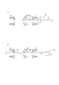
- (A) is an explanatory view showing in a simplified manner a state where a bar material is subjected to predetermined processing
- (b) is an explanatory view showing in a simplified state a state where a product is processed from the bar material.
- (A) is an explanatory view showing a simplified state of the machining of the bar material, and (b) shows a state in which the old material is transferred from the front spindle to the back spindle and the new material is supplied to the front spindle. It is explanatory drawing simplified and shown.
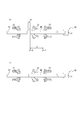
- FIG. 6 is an explanatory view showing in a simplified manner a state in which the end surfaces of the old material and the new material facing each other are brought into contact with each other by moving in a direction in which they approach each other.
- FIG. 4A is an explanatory view showing a simplified state in which the back surface spindle is moved to the front surface spindle side with the back surface chuck opened from the state shown in FIG. 4B, and FIG.
- FIG. (A) is an explanatory view showing a simplified state in which an old material and a new material are frictionally welded to each other
- (b) is a deburring process for a joint portion between the frictionally welded old material and new material
- FIG. 6C is an explanatory diagram showing a simplified state of performing the step
- FIG. 13C is an explanatory diagram showing a simplified state of the bar after completion of the deburring process.
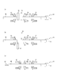
- (A) is an explanatory view showing a simplified state in which a bar, which is friction-welded between an old material and a new material, is pulled in to the front spindle side, and (b) is a friction-pressure contact between the old material and the new material. It is explanatory drawing which simplifies and shows the state which measures the protrusion length from the front chuck of the rod material which did.
- (A) is the explanatory view which simplifies and shows the state which is performing predetermined processing to the rod material which joined the old material and the new material
- (b) is the rod which joined the old material and the new material
- (A) is explanatory drawing which simplifies and shows the state which the joining part of the rod material which joined the old material and the new material was located in the front chuck, (b) is moving a front main spindle to an axial direction, It is explanatory drawing which simplifies and shows the state which is performing predetermined processing in the state which hold
- (A) is explanatory drawing which simplifies and shows the state which the joint part of the bar material which joined the old material and the new material was located in the guide bush, (b) is a new material rather than the joint part.
- (A)-(c) is explanatory drawing which shows the other method of measuring the axial direction position of a joining part.
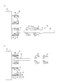
- (A), (b) is explanatory drawing which simplifies and shows the procedure which draws the rod material which carried out the friction welding of the old material and the new material to the front main spindle side by the rod material supply part.
- (A), (b) is explanatory drawing which simplifies the procedure which hold
- (A), (b) is explanatory drawing which simplifies and shows the procedure which performs predetermined
- (A) and (b) show a procedure in which a machine tool provided with a work clamp device performs a predetermined process on a final product gripped by a back chuck while gripping an old material by the work clamp device and pulling it out from the front spindle. It is explanatory drawing simplified and shown.
- the machine tool 1 shown in FIG. 1 is an automatic lathe (CNC lathe) that processes a long bar W as a work, and has a front spindle 10 as a first spindle and a back spindle 20 as a second spindle. is doing.
- CNC lathe automatic lathe
- the front spindle 10 and the back spindle 20 are arranged so as to face each other such that the axis of the front spindle 10 and the axis of the back spindle 20 are parallel to each other.
- the direction parallel to the axis of the front main shaft 10 and the back main shaft 20 is the Z-axis direction
- the direction orthogonal to the Z-axis direction is the X-axis direction
- the direction orthogonal to the Z-axis direction and the X-axis direction is the Y-axis direction.
- a front headstock 11 is installed on the base 2 so as to be movable in the Z-axis direction by a front-side moving mechanism 3 such as a guide rail mechanism.
- the front main spindle 10 is rotatably supported by holding the rod W on the front main spindle stock 11 and is rotationally driven by a main spindle motor.
- a main spindle motor for example, a built-in motor configured between the front spindle headstock 11 and the front spindle headstock 10 inside the front spindle headstock 11 can be adopted.
- a rear headstock 21 is installed on the base 2 so as to be movable in the Z-axis direction by a rear-side moving mechanism 4 such as a guide rail mechanism.
- the back spindle 20 is rotatably supported by holding the rod W on the back spindle stock 21 and is rotationally driven by a spindle motor.
- a spindle motor for example, a built-in motor configured between the back spindle 21 and the back spindle 20 inside the back spindle 21 can be adopted.
- An X-axis moving mechanism for moving the front spindle 10 relative to the rear spindle 20 in the X-axis direction is installed between the base 2 and the front spindle headstock 11 or between the base 2 and the rear spindle headstock 21. It Further, a Y-axis moving mechanism for relatively moving the front spindle 10 in the Y-axis direction with respect to the back spindle 20 is provided between the base 2 and the front spindle head 11 or between the base 2 and the back spindle 21. Is installed.
- a front chuck 12 as a first gripping means is provided at the tip of the front spindle 10 so as to be openable and closable.
- the front chuck 12 is housed inside the chuck sleeve 13.
- the tapered surface of the front chuck 12 is pressed by the tapered surface of the chuck sleeve 13, and the front chuck 12 is closed.
- the taper surface of the chuck sleeve 13 releases the pressure on the taper surface of the front chuck 12, and the front chuck 12 is opened.
- the front spindle 10 can hold the bar W by inserting the bar W with the front chuck 12 open and closing the front chuck 12.
- a back chuck 22 as a second gripping means is provided at the tip of the back spindle 20 so as to be openable and closable.
- the back surface chuck 22 is housed inside the chuck sleeve 23.
- the taper surface of the chuck sleeve 23 presses the taper surface of the back chuck 22, and the back chuck 22 is closed.
- the pressing of the taper surface of the chuck sleeve 23 against the taper surface of the back chuck 22 is released, and the back chuck 22 is opened.
- the back spindle 20 can hold the bar W by inserting the bar W with the back chuck 22 open and closing the back chuck 22.
- the slide driving mechanism of the chuck sleeves 13 and 23 does not limit the present invention, and various structures can be adopted.
- a guide bush 30 is provided between the front spindle 10 and the back spindle 20.
- the guide bush 30 is mounted on a guide bush support base 31 installed on the base 2 and arranged coaxially with the front main shaft 10. By adjusting the position of the guide bush 30 in the axial direction with respect to the guide bush supporting base 31, the guide bush 30 is adjusted to have an inner diameter corresponding to the outer diameter of the bar W.
- the guide bush 30 can guide the rod W so as to be movable in the Z-axis direction.
- the machine tool 1 includes a processing unit 40 as a processing means.
- the processing section 40 includes a tool 41 that processes the bar W.
- the tool 41 is held by a tool rest 42.
- the tool 41 is arranged in front of the guide bush 30 and is supported by the guide bush support base 31 so as to be movable in the X axis direction and the Y axis direction.
- the position of the tool rest 42 in the Z-axis direction is constant.
- an outer diameter cutting bite or a parting bite is mounted on the tool rest 42, and these can be appropriately switched according to the processing content by moving the tool rest 42, for example, in the X-axis direction.
- the machine tool 1 is provided with a back side fixed processing section 43 as a processing means.
- the back side fixed processing section 43 includes a plurality of (three) tools 44 for back side processing for processing the bar W.
- the tools 44 are each fixed to the base 2 via the back tool post 45, and can be appropriately switched according to the processing content by moving the back spindle 20 (back spindle head 21) in the Y-axis direction.
- the machine tool 1 is provided with a back side movement processing unit 46 as a processing means.
- the back side movement processing section 46 includes a tool 47 for processing the bar W.
- the tool 47 is held by a tool rest 48.
- the tool rest 48 is supported by the base 2 so as to be movable in the X-axis direction and the Y-axis direction.
- the position of the tool rest 48 in the Z-axis direction is constant.
- the tool rest 48 is equipped with, for example, an outer diameter cutting bite or a parting bite as the tool 47, which can be appropriately switched according to the processing content by moving the tool rest 48, for example, in the X-axis direction.
- the machine tool 1 includes a bar material supply unit (bar feeder) 50 arranged behind the front main spindle 10.
- the bar material supply unit 50 includes a finger 51 that grips the rear end of the bar material W and a drive rod 52 that drives the finger 51 in the Z-axis direction.
- the bar material supply unit 50 can sequentially supply the bar material W to the front main shaft 10. Further, the bar material supply unit 50 can pull in the bar material W projecting from the front main shaft 10 to the rear main shaft 20 side to the front main shaft 10 side.
- the machine tool 1 includes a control unit 60.
- the control unit 60 may be composed of, for example, a microcomputer including a storage unit such as a CPU (Central Processing Unit) and a memory.
- the control unit 60 includes a front spindle 10 (including the front spindle headstock 11 and the front chuck 12), a rear spindle 20 (including the rear spindle headstock 21, and a rear chuck 22), a machining unit 40, a backside fixed machining unit 43, a backside.
- the operations of the moving processing unit 46 and the bar material supply unit 50 can be integrally controlled.
- control unit 60 uses the processing unit 40, the back side fixed processing unit 43, and the back side moving processing unit 46 to perform predetermined processing on the bar W held by the front chuck 12 and the back chuck 22.
- the front spindle 10, the back spindle 20, the bar material supply unit 50, the machining unit 40, the back side fixed machining unit 43, and the back side moving machining unit 46 are operated so as to continuously perform the cut-off processing to obtain a plurality of products. It has a function as a product processing means.
- control unit 60 removes the bar W from the front main shaft 10 as the old material W1 and transfers it to the rear main shaft 20 after the completion of the processing of the bar W by the function as the product processing means. And has a function as an old material transfer means for operating the back main shaft 20.
- control unit 60 supplies the new rod W as the new rod W2 from the rod feeding unit 50 to the front spindle 10 from which the old rod W1 has been removed, and causes the front chuck 12 to hold the new rod W. It also has a function as a new material supply means for operating the bar material supply unit 50.
- control unit 60 joins the opposite ends of the old material W1 gripped by the back surface chuck 20 by the back surface chuck 22 and the new material W2 gripped by the front surface chuck 12 by the front surface spindle 10 to the old material W1. It has a function as a joining means for joining the new material W2 into one bar W3.
- control unit 60 removes the portion of the old material W1 of the rod material W3, which is formed by joining the old material W1 and the new material W2, by the function of the joining means, and removes the portion of the old material W1 from the back spindle 20 to the front spindle 10 side. It has a function as a retracting means for actuating the front main shaft 10, the rear main shaft 20, and the bar material supply unit 50 so as to be retracted.
- control unit 60 performs predetermined processing and cut-off processing on the bar material W3 drawn into the front spindle 10 by the function of the drawing means and gripped by the front chuck 12 by the function of the product processing means described above.
- control unit 60 has a function of controlling the operations of the front spindle 10, the back spindle 20, the bar material supply section 50, the processing section 40, the back side fixed processing section 43, and the back side moving processing section 46. .
- control unit 60 pulls the rod W3, which is formed by joining the old member W1 and the new member W2, into the front spindle 10 by the function as the pulling-in means and grips the rod W3 with the front chuck 12, and then the rod W3.
- the front main shaft 10, the back main spindle 20, and the bar material supply unit are arranged so that the front chuck 12 grips the part made of the old material W1 of the bar material W3. It has a function of controlling the operation of 50.
- control unit 60 has a function as a product processing unit, and the front chuck 12 is configured to continuously perform the predetermined processing and the cut-off processing on the bar W3 formed by joining the old material W1 and the new material W2. , And has a function as a gripper moving unit that moves the front spindle 10 (front chuck 12) so as to grip a portion of the rod W3 other than the joint 80 between the old material W1 and the new material W2.
- control unit 60 has a function as a product processing means, and when performing the predetermined processing and the cut-off processing on the bar material W3 obtained by joining the old material W1 and the new material W2 continuously, the control part 60 and the new material W1 are not used.
- the joint 80 with the material W2 is located in the guide bush 30, the front spindle 10, the rear spindle 20, the bar material are supplied so that the bar W3 is cut off on the new material W2 side of the joint 80. It has a function of controlling the operations of the section 50 and the processing section 40.
- the machine tool 1 is shown in FIG. 7B in order that the front chuck 12 recognizes the axial position of the joining portion 80 between the old material W1 and the new material W2 of the bar material W3 when performing the above control.
- the measuring rod 61 as the position recognizing unit or the old material position measuring terminal 62 as the position recognizing unit shown in FIG. 11C may be provided.
- the front spindle 10 and the back spindle 20 are omitted and only the front chuck 12 and the back chuck 22 are shown. However, the movement of the front chuck 12 is performed together with the movement of the front spindle 10, and It is assumed that the movement is performed together with the movement of the back spindle 20.
- the front chuck 12 grips the bar material W.
- the bar W held by the front spindle 10 (front chuck 12) is in a state of protruding from the guide bush 30 toward the back spindle 20 by a predetermined length.
- the front spindle 10 is rotationally driven by the spindle motor to rotate the bar W.
- the selected tool 41 of the machining unit 40 is moved in the Y-axis direction (cutting direction) to cut into the bar W, and the front spindle 10 (front spindle headstock 11) is moved to the Z-axis.
- the bar W can be subjected to predetermined processing (cutting).
- the rear main shaft 20 After subjecting the bar W held by the front main shaft 10 to a predetermined process, the rear main shaft 20 is arranged coaxially with the front main shaft 10, and the end of the bar W held by the front main shaft 10 is attached to the rear main shaft 20.
- the rod material W is gripped by the back chuck 22 and the rod material W is cut off by the tool 41 in this state, so that the cut rod material W can be transferred from the front main spindle 10 to the back main spindle 20.
- the rod material W can be processed (cut) by the selected tool 44 of the rear surface side fixed processing portion 43 by moving the rear surface main shaft 20 in the Y axis direction or the Z axis direction. Further, the bar material W can be processed by the tool 47 of the back side moving processing unit 46. By the processing, the bar W is made into the product P. The completed product P is taken out from the back spindle 20 and conveyed to the next step.
- the bar W is fed out by the bar supply unit 50 on the side of the front main shaft 10, and again, as described above, the predetermined processing and the cut-off of the bar W on the front main shaft 10. Processing is performed. Similarly, a plurality of products P having a predetermined shape can be obtained from one long bar W by feeding out the bar W and repeating predetermined processing and cut-off processing.
- the back spindle 20 moves so as to approach the front spindle 10.
- the gripping of the old material W1 by the front chuck 12 is released, and the old material W1 is gripped by the back surface chuck 22.
- the old material W1 is passed from the front spindle 10 to the back spindle 20 by causing the back chuck 22 to grip the old material W1.
- the back main spindle 20 that has received the old material W1 moves in the Z-axis direction so as to separate from the front main spindle 10 while holding the old material W1.
- a new bar material W is supplied as a new material W2 from the bar material supply unit 50 to the front spindle 10.
- the new material W2 is gripped by the front chuck 12 to be in the state shown in FIG. 3 (b).
- the tip of the new material W2 facing the back spindle 20 is end-face processed by the tool 41.
- the tool 41 is supported by the guide bush support base 31 and the position in the Z-axis direction (Z1-0) is determined, and the Z-axis position (Z1-1) of the front chuck 12 also controls the position of the front chuck 12. Since it is recognized by the control unit 60, the control unit 60 can calculate the protruding length A of the new material W2 from the front chuck 12.
- the front main shaft 10 and the back main shaft 20 are moved in the Z-axis direction so as to approach each other, and as shown in FIG. 4 (b), the end surfaces of the old material W1 and the new material W2 facing each other are brought into contact with each other.
- the back spindle 20 is set to the torque skip state (the movement of the back spindle is stopped by detecting the torque change of the motor in the back side moving mechanism 4 when the end faces abut each other), whereby the old material W1 When the opposite end surfaces of the new material W2 and the new material W2 come into contact with each other, the displacement of the old material W1 or the new material W2 with respect to the back main spindle 20 or the front main spindle 10 or the movement of the front main spindle 10 in the Z-axis direction does not occur. There is.
- the rear surface chuck 22 is opened while the end surfaces are in contact with each other, and the rear surface spindle 20 is moved to the front surface spindle 10 side.
- the back side chuck 22 is made to grip the tip side portion near the material W2.
- the back spindle 20 is moved in the Z-axis direction away from the front spindle 10, and the end surface of the old material W1 and the end surface of the new material W2 are separated from each other, respectively.
- the recesses 70 and 71 are processed using the tools 41 to 44 and the like.
- Friction welding can be performed by the following procedures, for example.
- the rear main shaft 20 is moved in the Z-axis direction toward the front main shaft 10 in the torque skip state, and the end surface of the old material W1 and the end surface of the new material W2 are moved to each other as shown in FIG. 6 (a). Abut. Then, from the position where the end surface of the old material W1 and the end surface of the new material W2 are in contact with each other, the back spindle 20 is further moved in the Z-axis direction by a predetermined distance (for example, 0.3 mm) toward the front spindle 10. Then, the end surface of the old material W1 and the end surface of the new material W2 are brought into contact with each other at a predetermined pressure.
- a predetermined distance for example, 0.3 mm
- the front main spindle 10 and the rear main spindle 20 are rotated relative to each other by rotating only the rear main spindle 20 at a predetermined speed while stopping the front main spindle 10 without rotating the front main spindle 10 and the end surface of the old material W1.
- Friction heat is generated between the end surface of the new material W2 and the end surface of the old material W1 by rotating only the front main spindle 10 at a predetermined speed while stopping the rear main spindle 20 without rotating it.
- the machine tool 1 uses the tool 41 to perform a cutting process for removing the burr 90 from the bar material W3.
- the tool 41 is pressed against the burr 90 while the bar W3 is held by at least one of the front spindle 10 and the back spindle 20, while rotating the holding front spindle 10 or the back spindle 20. It can be easily done by applying.
- the frictional pressure welding can be easily performed by processing the recesses 70 and 71 on the end surface of the old material W1 and the end surface of the new material W2, but without processing the recesses 70 and 71. Friction welding may be performed.
- the back spindle 20 is moved in the Z-axis direction and the Y-axis direction, and the tip of the measuring rod 61 fixed to the back spindle stock 21 of the back spindle 20 is replaced with the old material.
- the rear end face of W1 facing away from the front main shaft 10 is brought into contact with the rear end face in a torque skip state.
- the control unit 60 that controls the position of the back spindle 20 recognizes the position of the tip of the measuring rod 61 in the Z-axis direction. You can Further, as described above, the control unit 60 can also recognize the position of the front chuck 12 in the Z-axis direction. Therefore, by bringing the tip of the measuring rod 61 into contact with the rear end surface of the old material W1, the control unit 60 can calculate the protruding length B of the rod W3 from the front chuck 12.
- the ends of the old material W1 and the new material W2, which form the rod material W3, are crushed at the joining portion during friction welding, and the crushing length ⁇ is Z between the front spindle 10 and the back spindle 20 during friction welding. It can be calculated from the relative amount of movement in the axial direction.
- the end face of the rod W3 is processed by the tool 41, and the front spindle 10 is opened with the front chuck 12 opened while pressing the end face with the tool 41. It moves in the Z-axis direction so as to approach the back spindle 20. Then, as shown in FIG. 8A, the front chuck 12 grips the portion of the rod W3 made of the old material W1. Then, as shown in FIGS. 8A and 8B, in this state, the front spindle 10 is rotationally driven by the spindle motor to rotate the bar W3, and the selected tool 41 of the machining unit 40 is moved to Y.
- the bar W3 is moved in the axial direction (cutting direction) to cut into the bar W3, and the front spindle 10 (front headstock 11) is moved in the Z axis direction (feed direction) to perform a predetermined machining (cutting) on the bar W3. And the parting process is continuously performed to process a plurality of products P from the bar W3.
- the machine tool 1 of the present embodiment first, for forming the product P on the bar material W3 in which the old material W1 and the new material W2 are joined.
- the front chuck 12 grips the portion of the rod W3 made of the old material W1. Therefore, at the time of the processing, the weak joint portion 80 is prevented from being located between the portion processed by the tool 41 and the portion gripped by the front chuck 12, and the old material W1 of the rod W3 is removed from the old material W1. It is possible to perform the processing in a state in which the front portion is securely held by the front chuck 12. As a result, the portion of the rod W3 made of the old material W1 can be accurately processed.
- the bar material W3, in which the old material W1 and the new material W2 are joined is continuously subjected to the predetermined processing and the cut-off processing for forming the product P, it is shown in FIG. 9 (a).
- the axial position of the front chuck 12 and the axial position of the joint portion 80 of the bar W may coincide with each other.
- the bar W3 cannot be reliably gripped by the front chuck 12, and the machining accuracy of the bar W3 is reduced. There is a risk.
- the bar W3 is formed on both sides of the joint 80 on the outer peripheral surface of the bar W3. Since a reduced diameter portion 81 having a smaller diameter than the outer peripheral surface of the rod is generated, when the front chuck 12 grips the portion of the joint portion 80 of the bar W3, the front chuck 12 and the joint portion 80 or the reduced diameter portion 81 are separated from each other. There is a possibility that a gap may be generated in the rod W3 and rattling may occur in the rod W3, and the processing accuracy of the rod W3 may be significantly reduced.
- the control unit 60 continuously performs the predetermined machining and the cut-off machining on the rod W3 and the axial position of the front chuck 12 and the rod W3.
- the front main spindle 10 front chuck 12
- the rod is moved by the front chuck 12.
- the control for gripping the portion of the material W3 made of the new material W2 is performed. As a result, as shown in FIGS.
- a portion of the rod W3 other than the joining portion 80 between the old material W1 and the new material W2 is gripped by the front chuck 12, that is, the front surface.
- Predetermined processing and cut-off processing by the tool 41 can be performed while the bar material W3 is securely held by the chuck 12. Therefore, the bar W3 can be processed accurately.
- the controller 60 can always accurately recognize the axial position of the joint 80 on the rod W3 by the procedure using the measuring rod 61 described above.
- the control unit 60 grips the front chuck 12 on the portion other than the joining portion 80 between the old material W1 and the new material W2 of the rod material W3, based on the correctly recognized axial position of the joining portion 80 on the rod material W3.
- the movement of the front main spindle 10 in the Z-axis direction can be accurately controlled. Therefore, the front chuck 12 can hold the bar W3 more reliably, and the bar W3 can be processed more accurately.
- the controller 60 joins the old material W1 and the new material W2 by friction welding and then performs a process of cutting off the burr 90, when the axial position of the front chuck 12 and the reduced diameter portion 81 of the bar material W3. It is preferable to move the front main spindle 10 in the Z-axis direction even when the position coincides with the axial position. This prevents the front chuck 12 from gripping not only the joint portion 80 of the rod W3 but also the portion of the reduced diameter portion 81, so that the rod W3 can be processed more reliably and accurately.
- the front spindle 10 (front chuck 12) is moved in a direction away from the back spindle 20.
- the front chuck 12 grips the portion of the bar W3 made of the new material W2.
- the front main spindle 10 front chuck 12
- the portion of the rod W3 made of the old material W1 may be gripped by the rod 12.
- the front chuck 12 can hold a position closer to the processed portion of the bar W3.
- the bar W3 can be held more reliably by the front chuck 12, and the bar W3 can be processed more accurately.
- the control unit 60 continuously performs the predetermined processing and the cut-off processing on the bar W ⁇ b> 3.
- the predetermined processing for the rod W3 is completed and the rod W3 is joined as shown in FIG. 10 (b). It is possible to adopt a configuration in which the parting control is performed on the new material W2 side of the part 80. As a result, it is possible to prevent the portion of the rod W3 having the joint portion 80 from being processed as the product P.
- control unit 60 processes the product P from the portion made of the old material W1 of the bar W in advance based on the axial position of the joint 80 so that the guide bush 30 does not support the joint 80.
- the number may be set.
- the predetermined processing for the bar W3 is completed, and the bar W3 is positioned closer to the new material W2 than the joint 80. You may make it control the parting off. As a result, it is possible to prevent the portion of the rod W3 having the reduced diameter portion 81 from being processed as the product P.
- the method for causing the controller 60 to recognize the position of the joint 80 in the Z-axis direction is not limited to the method using the measuring rod 61 described above, and various methods or configurations can be adopted.
- the amount of protrusion of the old material W1 from the back chuck 22 is adjusted by the back side positioning plate 72.
- the amount of protrusion of the new material W2 from the front chuck 12 is measured by the front side positioning plate 73, and the end surface of the old material W1 and the end surface of the new material W2 are, if necessary, measured as shown in FIG. 11B.
- 11C the end surface of the old material W1 and the end surface of the new material W2 are brought into contact with each other, and the position of the rear end surface of the old material W1 is adjusted by the old material position measuring terminal 62, as shown in FIG. 11C.
- the protruding amount of the old material W1 from the back chuck 22, the protruding amount of the new material W2 from the front chuck 12, and the old material position measuring terminal 62. May be calculated the position of the joint portion 80 on the basis of the position of the rear end face of the constant has been old wood W1.
- the method for causing the control unit 60 to recognize the position of the joining portion 80 in the Z-axis direction is not limited to the above.
- a bar material W3 obtained by joining the old material W1 and the new material W2 is photographed by a camera.
- Various methods such as a method of detecting the position of the joint 80 in the Z-axis direction based on the machining program of 60 and a method of calculating the position of the joint 80 in the Z-axis direction based on the machining length of the bar W are adopted. can do.
- the front chuck 12 holds the bar W3 and the rear chuck W3 is held.
- the bar W3 of 22 is pulled out from the back main shaft 20 by moving the front main shaft 10 in the Z-axis direction in a direction away from the back main shaft 20 with the gripping of the bar W3 being released.
- the bar material supply unit 50 has a function of drawing the bar material W protruding from the front main shaft 10 toward the back main shaft 20 toward the front main shaft 10, and therefore, using the function, FIG. As shown in a), after joining the old material W1 and the new material W2 into one bar W3, as shown in FIG.
- the bar material supply unit 50 replaces the bar material W3 with the old material W1. Only by moving toward the side of the front main shaft 10 may be configured to pull the rod W3 from back spindle 20 is.
- the control unit 60 as the pulling-in means pulls out the part of the old material W1 of the bar W3 from the back main shaft 20 and pulls it into the front main shaft 10 side, so that the front main shaft 10, the back main shaft 20, and the bar The operation of the supply unit 50 is controlled.
- the bar material W3 is gripped by the front chuck 12 and the back surface chuck 22 is pressed.
- the gripping of the bar W3 is released, and the rear end of the bar W3 is gripped by the fingers 51 of the bar supply unit 50.
- the rod W3 is driven by the drive rod 52 as shown in FIG.
- the finger 51 moves in the Z-axis direction by the length of the old material W1 in the backward direction away from the back spindle 20.
- the rod material W3 can be drawn into the front spindle 10 side by the rod supply portion 50 and can be removed from the back spindle 20.
- the front main shaft 10 is rotationally driven by the main shaft motor to rotate the bar W3 in the same manner as shown in FIGS. 8 (a) and 8 (b).
- the selected tool 41 of the part 40 is moved in the Y-axis direction (cutting direction) to cut into the rod W3, and the front spindle 10 (front spindle stock 11) is moved in the Z-axis direction (feed direction) to move the rod. It is possible to process a plurality of products P from the bar material W3 by continuously performing the predetermined processing (cutting processing) and the cut-off processing on the material W3.
- the bar material W3 since the bar material W3 is moved by the length of the old material W1 by the bar material supply part 50, the bar material W3 after the movement is processed by the processing part 40 or the like. It can be in a state of protruding from the front spindle 10 by a suitable predetermined amount. As a result, immediately after the movement, the processing section 40 performs a predetermined process for forming the product P on the bar material W3 that is removed from the back spindle 20 and gripped by the front chuck 12 of the front spindle 10. And it is possible to perform a parting process.
- the old material W1 is held by the back surface chuck 22 of the back surface spindle 20, but the work clamp device 24 installed on the back surface spindle 20 having an axis parallel to the axis of the back surface spindle 20 is used. It is also possible to provide.
- a work clamp device 24 is provided on the back spindle 21 of the back spindle 20 so as to be aligned with the back spindle 20 such that the axis is parallel to the axis of the back spindle 20. be able to.
- the work clamp device 24 includes a clamp chuck (clamp side gripping means) 24 a having the same configuration as the back surface chuck 22.
- the inner diameter of the clamp chuck 24a is the same as the inner diameter of the front chuck 12, and the work clamping device 24 can grip the old material W1 detached from the front spindle 10 by the clamp chuck 24a.
- the inner diameter of the back surface chuck 22 is smaller than the inner diameter of the front surface chuck 12, and the back surface chuck 12 is gripped by the front surface chuck 12 and subjected to predetermined processing by the processing portion 40 on the front surface main shaft 10, whereby the back surface main shaft 10 is processed.
- the back chuck 22 can grip a work (product P) whose outer diameter of the tip facing 20 is smaller than the outer diameter of the bar W.
- the work clamp device 24 grips the old material W1 and the front chuck 12 of the front spindle 10 grips the new material W2 and mutually.
- the bar W3 can be formed by bringing the end faces of the above into contact and performing friction welding.
- the final work (product P) processed by the front spindle 10 and cut off from the bar W is held by the rear chuck 22 of the rear spindle 20.
- the gripping of the old material W1 by the front chuck 12 is released, and the old material W1 is gripped by the clamp chuck 24a of the work clamp device 24.
- the old material W1 is removed from the front main spindle 10 by moving in the Z-axis direction away from the front main spindle 10.
- a new bar W is supplied as a new bar W2 from the bar bar supply unit 50 to the front spindle 10, and the new bar W2 is gripped by the front chuck 12.
- the end surfaces of the old material W1 and the new material W2 that face each other are brought into contact with each other, and the old material W1 and the new material W2 are friction-welded.
- the old material W1 and the new material W2 can be combined into one bar W3 with the axial end surfaces of the old material W1 and the new material W2 as the bonding surfaces.
- the back spindle 21 is provided with the back spindle 20 and the work clamp device 24. Therefore, as shown in FIG. 14B, the friction welding between the old material W1 and the new material W2 and the back welding are performed.
- the final work (product P) gripped by the back surface chuck 22 of the main shaft 20 can be simultaneously subjected to predetermined processing by the tool 47 of the back side moving processing section 46. As a result, the time required to complete the friction welding between the old material W1 and the new material W2 can be shortened.
- the old material W1 may be grasped by the clamp chuck 24a of the work clamp device 24 provided on the back spindle 21. Therefore, the inner diameter of the back chuck 22 of the back spindle 20 can be made smaller than the inner diameter of the front chuck 12 of the front spindle 10 in accordance with the work (product P) processed by the front spindle 10. As a result, the machine tool 1 can be adapted to manufacture products P having various shapes.
- the tool 47 of the back side movement processing unit 46 for the final work (product P) gripped by the back chuck 22 of the back spindle 20 As shown in FIG. 15 (a), the predetermined work by (1) is continuously performed after the final work (product P) obtained by processing the bar W3 with the front main spindle 10 is transferred from the front main spindle 10 to the back main spindle 20. It is also possible. That is, as shown in FIG. 15A, after the final work (product P) is transferred from the front spindle 10 to the back spindle 20, the final work (product P) is processed by the tool 47 of the back side movement processing unit 46.
- the back spindle 21 is provided with the work clamp device 24 in addition to the back spindle 20, while the back spindle 20 is gripping the old material W1,
- the product P can be subjected to predetermined processing by the tool 47 of the back side moving processing portion 46.
- the inner diameter of the front chuck 12 and the work clamp device 24 are the same, and the inner diameter of the back chuck 22 of the back spindle 20 is
- the final work (product P) is transferred from the front main spindle 10 to the back main spindle 20 and then the final work is carried out, and then the old material W1 and the new material Friction pressure contact with W2 can be performed between the work clamp device 24 and the front chuck 12.
- the old material W1 and the new material W2 are joined by friction welding, but the invention is not limited to this.
- a concave portion may be formed on one end of the old material W1 and the new material W2. Is provided, a convex portion is provided on the other of the old material W1 and the new material W2, and the old material W1 and the new material W2 are joined by fitting them, and the joining means can be variously changed. .
- the machine tool 1 includes the guide bush 30, but the guide bush 30 may be omitted.
Priority Applications (5)
| Application Number | Priority Date | Filing Date | Title |
|---|---|---|---|
| US17/288,643 US20210402483A1 (en) | 2018-10-26 | 2019-10-24 | Machine tool |
| CN201980069440.3A CN112888519B (zh) | 2018-10-26 | 2019-10-24 | 机床 |
| EP19875513.4A EP3871813A4 (en) | 2018-10-26 | 2019-10-24 | MACHINE TOOL |
| KR1020217011959A KR102602752B1 (ko) | 2018-10-26 | 2019-10-24 | 공작기계 |
| JP2020552604A JP7312763B2 (ja) | 2018-10-26 | 2019-10-24 | 工作機械 |
Applications Claiming Priority (4)
| Application Number | Priority Date | Filing Date | Title |
|---|---|---|---|
| JP2018-202338 | 2018-10-26 | ||
| JP2018202338 | 2018-10-26 | ||
| JP2018241512 | 2018-12-25 | ||
| JP2018-241512 | 2018-12-25 |
Publications (1)
| Publication Number | Publication Date |
|---|---|
| WO2020085454A1 true WO2020085454A1 (ja) | 2020-04-30 |
Family
ID=70330548
Family Applications (1)
| Application Number | Title | Priority Date | Filing Date |
|---|---|---|---|
| PCT/JP2019/041781 WO2020085454A1 (ja) | 2018-10-26 | 2019-10-24 | 工作機械 |
Country Status (7)
| Country | Link |
|---|---|
| US (1) | US20210402483A1 (zh) |
| EP (1) | EP3871813A4 (zh) |
| JP (1) | JP7312763B2 (zh) |
| KR (1) | KR102602752B1 (zh) |
| CN (1) | CN112888519B (zh) |
| TW (1) | TWI803707B (zh) |
| WO (1) | WO2020085454A1 (zh) |
Cited By (1)
| Publication number | Priority date | Publication date | Assignee | Title |
|---|---|---|---|---|
| WO2021002133A1 (ja) * | 2019-07-04 | 2021-01-07 | シチズン時計株式会社 | 工作機械及び加工方法 |
Citations (5)
| Publication number | Priority date | Publication date | Assignee | Title |
|---|---|---|---|---|
| JPS5255929U (zh) * | 1975-10-16 | 1977-04-22 | ||
| JPH079201A (ja) * | 1993-06-29 | 1995-01-13 | Citizen Watch Co Ltd | 旋盤及び旋盤による加工方法 |
| JP2004050303A (ja) * | 2002-07-16 | 2004-02-19 | Shin Etsu Chem Co Ltd | ワークの加工方法及び加工装置 |
| JP2008246648A (ja) * | 2007-03-30 | 2008-10-16 | Citizen Holdings Co Ltd | ワーク加工機、このワーク加工機を用いたワーク加工システム及びワーク加工方法 |
| JP2015174179A (ja) | 2014-03-14 | 2015-10-05 | シチズンホールディングス株式会社 | ワーク加工装置およびワーク加工方法 |
Family Cites Families (30)
| Publication number | Priority date | Publication date | Assignee | Title |
|---|---|---|---|---|
| US3541669A (en) * | 1968-11-20 | 1970-11-24 | Caterpillar Tractor Co | Orienting inertia welded parts |
| JPS5024695B1 (zh) * | 1969-02-20 | 1975-08-18 | ||
| US3717295A (en) * | 1971-03-17 | 1973-02-20 | Clarke Chapman Thompson J Ltd | Friction welding or like machines |
| JP2639403B2 (ja) * | 1988-07-29 | 1997-08-13 | 株式会社ツガミ | 工作機械及び棒材継ぎ足し装置 |
| JPH04240003A (ja) * | 1991-01-21 | 1992-08-27 | Tsugami Corp | 精密自動旋盤 |
| JP2788231B2 (ja) * | 1996-09-04 | 1998-08-20 | 川崎重工業株式会社 | 長尺バー材加工装置とその加工方法 |
| US5858142A (en) * | 1997-02-27 | 1999-01-12 | Inertia Friction Welding, Inc. | Angular orientation control system for friction welding |
| JP2000271803A (ja) * | 1999-03-25 | 2000-10-03 | Star Micronics Co Ltd | 数値制御旋盤のワーク供給・排出方法と数値制御旋盤 |
| JP2004114226A (ja) * | 2002-09-26 | 2004-04-15 | Mori Seiki Hitech Co Ltd | 主軸移動型立形工作機械 |
| JP2005125482A (ja) * | 2003-10-03 | 2005-05-19 | Tsugami Corp | 旋盤 |
| DE102004012653A1 (de) * | 2004-03-16 | 2005-10-06 | Mtu Aero Engines Gmbh | Rotationsreibschweißverfahren sowie Rotationsreibschweißanlage |
| DE202004009909U1 (de) * | 2004-06-23 | 2005-11-03 | Kuka Schweissanlagen Gmbh | Reibschweißmaschine |
| JP2009166165A (ja) * | 2008-01-15 | 2009-07-30 | Star Micronics Co Ltd | 工作機械及びその制御方法 |
| JP5255929B2 (ja) | 2008-07-04 | 2013-08-07 | ルネサスエレクトロニクス株式会社 | 半導体装置 |
| CN102089102B (zh) * | 2008-07-10 | 2013-05-08 | 西铁城精机宫野股份有限公司 | 工件加工装置及工件加工方法 |
| JP2011079110A (ja) * | 2009-10-09 | 2011-04-21 | Eguro:Kk | 工作機械 |
| JP5854811B2 (ja) * | 2011-12-19 | 2016-02-09 | Dmg森精機株式会社 | 工作機械 |
| FR2992880B1 (fr) * | 2012-07-06 | 2015-02-13 | Snecma | Piece pour soudage par friction |
| ES2871819T3 (es) * | 2012-12-12 | 2021-11-02 | Sandvik Mat Tech Deutschland | Máquina de tratamiento y método para trabajar el extremo de una tubería |
| WO2015074723A1 (en) * | 2013-11-25 | 2015-05-28 | Lns Management Sa | Bar feeder |
| WO2016021454A1 (ja) * | 2014-08-07 | 2016-02-11 | シチズンホールディングス株式会社 | 工作機械及び材料の加工方法 |
| CN204975676U (zh) * | 2015-08-20 | 2016-01-20 | 福建中网电力科技有限公司 | 一种电力金具自动摩擦焊接设备 |
| JP6867957B2 (ja) * | 2016-02-04 | 2021-05-12 | シチズン時計株式会社 | 工作機械及びその工作機械の制御装置 |
| DE102016122746A1 (de) | 2016-11-25 | 2018-05-30 | Ensinger Gmbh | Drehmaschine und Verfahren zum Drehen von Werkstücken |
| JP6892593B2 (ja) * | 2017-03-14 | 2021-06-23 | スター精密株式会社 | 工作機械 |
| KR102533754B1 (ko) * | 2017-11-27 | 2023-05-17 | 시티즌 도케이 가부시키가이샤 | 마찰 압접 방법 및 공작 기계 |
| CN108637702A (zh) * | 2018-07-11 | 2018-10-12 | 广东人励智能工程有限公司 | 一种智能焊接设备 |
| JP7261799B2 (ja) * | 2018-07-18 | 2023-04-20 | シチズン時計株式会社 | 工作機械 |
| DE102019110664A1 (de) * | 2019-04-25 | 2020-10-29 | Kuka Deutschland Gmbh | Verfahren und Vorrichtung zum Reibstromfügen |
| CN110202387B (zh) * | 2019-07-16 | 2024-03-22 | 宁波万盛智能科技股份有限公司 | 一种传动轴的加工装置 |
-
2019
- 2019-10-24 CN CN201980069440.3A patent/CN112888519B/zh active Active
- 2019-10-24 WO PCT/JP2019/041781 patent/WO2020085454A1/ja unknown
- 2019-10-24 KR KR1020217011959A patent/KR102602752B1/ko active IP Right Grant
- 2019-10-24 EP EP19875513.4A patent/EP3871813A4/en active Pending
- 2019-10-24 US US17/288,643 patent/US20210402483A1/en active Pending
- 2019-10-24 JP JP2020552604A patent/JP7312763B2/ja active Active
- 2019-10-25 TW TW108138699A patent/TWI803707B/zh active
Patent Citations (5)
| Publication number | Priority date | Publication date | Assignee | Title |
|---|---|---|---|---|
| JPS5255929U (zh) * | 1975-10-16 | 1977-04-22 | ||
| JPH079201A (ja) * | 1993-06-29 | 1995-01-13 | Citizen Watch Co Ltd | 旋盤及び旋盤による加工方法 |
| JP2004050303A (ja) * | 2002-07-16 | 2004-02-19 | Shin Etsu Chem Co Ltd | ワークの加工方法及び加工装置 |
| JP2008246648A (ja) * | 2007-03-30 | 2008-10-16 | Citizen Holdings Co Ltd | ワーク加工機、このワーク加工機を用いたワーク加工システム及びワーク加工方法 |
| JP2015174179A (ja) | 2014-03-14 | 2015-10-05 | シチズンホールディングス株式会社 | ワーク加工装置およびワーク加工方法 |
Cited By (2)
| Publication number | Priority date | Publication date | Assignee | Title |
|---|---|---|---|---|
| WO2021002133A1 (ja) * | 2019-07-04 | 2021-01-07 | シチズン時計株式会社 | 工作機械及び加工方法 |
| EP3995239A4 (en) * | 2019-07-04 | 2023-08-09 | Citizen Watch Co., Ltd. | MACHINE TOOLS AND MACHINING PROCESSES |
Also Published As
| Publication number | Publication date |
|---|---|
| JP7312763B2 (ja) | 2023-07-21 |
| KR102602752B1 (ko) | 2023-11-15 |
| KR20210081348A (ko) | 2021-07-01 |
| US20210402483A1 (en) | 2021-12-30 |
| TW202019586A (zh) | 2020-06-01 |
| EP3871813A4 (en) | 2022-08-10 |
| EP3871813A1 (en) | 2021-09-01 |
| CN112888519B (zh) | 2024-03-26 |
| CN112888519A (zh) | 2021-06-01 |
| TWI803707B (zh) | 2023-06-01 |
| JPWO2020085454A1 (ja) | 2021-09-09 |
Similar Documents
| Publication | Publication Date | Title |
|---|---|---|
| WO2020085453A1 (ja) | 工作機械 | |
| EP3718674B1 (en) | Friction welding method and machine tool | |
| JP6270561B2 (ja) | ワーク加工装置およびワーク加工方法 | |
| WO2020017514A1 (ja) | 工作機械 | |
| WO2020085454A1 (ja) | 工作機械 | |
| JPH02232102A (ja) | Nc旋盤の残材加工方法 | |
| WO2020085455A1 (ja) | 工作機械 | |
| CN113950384B (zh) | 机床和加工方法 | |
| WO2022004625A1 (ja) | 工作機械、工作機械の制御方法 | |
| JP5668241B2 (ja) | ワーク切断確認装置、ワーク切断システムおよびワーク切断確認方法 | |
| JPH10235495A (ja) | パイプ加工装置のパイプ支持方法およびその装置 | |
| JP2010052073A (ja) | 旋盤及びその制御方法 | |
| JP7413036B2 (ja) | 工作機械 | |
| JP2000271803A (ja) | 数値制御旋盤のワーク供給・排出方法と数値制御旋盤 | |
| JP2020196107A (ja) | 工作機械及び加工方法 |
Legal Events
| Date | Code | Title | Description |
|---|---|---|---|
| 121 | Ep: the epo has been informed by wipo that ep was designated in this application |
Ref document number: 19875513 Country of ref document: EP Kind code of ref document: A1 |
|
| ENP | Entry into the national phase |
Ref document number: 2020552604 Country of ref document: JP Kind code of ref document: A |
|
| NENP | Non-entry into the national phase |
Ref country code: DE |
|
| ENP | Entry into the national phase |
Ref document number: 2019875513 Country of ref document: EP Effective date: 20210526 |