WO2020085249A1 - 環境試験室、及び、それに用いる整流部材 - Google Patents
環境試験室、及び、それに用いる整流部材 Download PDFInfo
- Publication number
- WO2020085249A1 WO2020085249A1 PCT/JP2019/041186 JP2019041186W WO2020085249A1 WO 2020085249 A1 WO2020085249 A1 WO 2020085249A1 JP 2019041186 W JP2019041186 W JP 2019041186W WO 2020085249 A1 WO2020085249 A1 WO 2020085249A1
- Authority
- WO
- WIPO (PCT)
- Prior art keywords
- environmental test
- air
- temperature
- curtain
- test chamber
- Prior art date
- Legal status (The legal status is an assumption and is not a legal conclusion. Google has not performed a legal analysis and makes no representation as to the accuracy of the status listed.)
- Ceased
Links
Images










Classifications
-
- F—MECHANICAL ENGINEERING; LIGHTING; HEATING; WEAPONS; BLASTING
- F24—HEATING; RANGES; VENTILATING
- F24F—AIR-CONDITIONING; AIR-HUMIDIFICATION; VENTILATION; USE OF AIR CURRENTS FOR SCREENING
- F24F13/00—Details common to, or for air-conditioning, air-humidification, ventilation or use of air currents for screening
- F24F13/02—Ducting arrangements
-
- G—PHYSICS
- G01—MEASURING; TESTING
- G01N—INVESTIGATING OR ANALYSING MATERIALS BY DETERMINING THEIR CHEMICAL OR PHYSICAL PROPERTIES
- G01N17/00—Investigating resistance of materials to the weather, to corrosion, or to light
Definitions
- the present invention relates to an environmental test room and a rectifying member used for it.
- optical instruments for astronomical observation require highly accurate measurement of the lens surface shape and structure dimensions on the order of nanometers (nm).
- optical measurement using an optical measuring device such as a laser interferometer is generally used.
- Non-Patent Document 1 when using a laser interferometer in an atmospheric pressure environment, it is known that variations due to fluctuations in atmospheric temperature, humidity, pressure, etc. affect measurement (see, for example, Non-Patent Document 1). Therefore, when performing high-accuracy optical measurement, it is common to make the optical path space a vacuum and perform measurement in a state in which the influence of fluctuations such as atmospheric temperature, humidity, and pressure is eliminated (for example, Non-Patent Documents). 2).
- Patent Document 1 it has been proposed to stabilize the measurement environment by air conditioning control in order to perform highly accurate measurement under atmospheric pressure environment.
- the local space described in Patent Document 1 is used as an environmental test room, and an object to be measured (test object) and an optical measuring device are installed in the environmental test room to perform optical measurement.
- the fluctuations in the temperature of the object to be measured and the optical measuring device are generated by, for example, heat transfer from the heat convection inside the environmental test room and radiant heat from the wall or floor.
- the temperature of the wall surface of the environmental test room will be lower than the temperature of the conditioned air.
- the temperature of the wall surface of the environmental test room becomes higher than the temperature of the conditioned air.
- the object to be measured or the optical measuring device is expected to be the same temperature as the set temperature of the conditioned air, but in the above-mentioned situation, there is a temperature difference between the object to be measured or the optical measuring device and the wall surface of the environmental test room.
- the present invention has been made to solve the above-mentioned problems, and its main purpose is to enable highly accurate optical measurement under atmospheric pressure environment.
- the present invention is an environmental test room, wherein a supply port to which conditioned air at a predetermined temperature is supplied at a predetermined wind speed and a discharge port that is arranged to face the supply port and discharges the conditioned air.
- a rectifying member that is arranged between the side wall surface of the flow path portion and the installation portion and that rectifies the airflow of the conditioned air, the side wall surface of the flow path portion and the rectifying member are the supply It is arranged so as to be parallel to the air flow direction of the conditioned air flowing from the mouth toward the exhaust port, and has a diffuse reflection surface on the surface on the side of the installation portion.
- the rectifying member may be composed of a cloth curtain that can be expanded and stored. Other means will be described later.
- highly accurate optical measurement can be performed under atmospheric pressure environment.
- FIG. 1 is a configuration diagram of an entire air conditioning system including an environmental test room according to the present embodiment.
- the air conditioning system 1 includes a dehumidifying unit 3, a dry air temperature control unit 4, a dry air heating unit 5, a circulation flow path 6, a blower 41, heaters 51 and 54, a heat storage body 55, and the like. There is.
- the air conditioning system 1 air-conditions the air discharged from the discharge port 2out of the environmental test chamber 2 through the circulation flow path 6 and returns it to the supply port 2in of the environmental test chamber 2 to circulate the conditioned air in the system. .
- the dehumidifying unit 3 includes a dehumidifier such as a desiccant air conditioner 30 and sends dry air obtained by dehumidifying the air mixed with the air discharged from the environmental test chamber 2 to the dry air temperature controlling unit 4. .
- the dry air temperature adjusting unit 4 adjusts the temperature of the dry air sent from the dehumidifying unit 3 to a temperature slightly lower than the set air temperature inside the environmental test chamber 2, and sends the temperature to the dry air heating unit 5.
- the dry air heating unit 5 heats up to the set air temperature inside the environmental test chamber 2 and sends the air into the environmental test chamber 2.
- the inside of the environmental test chamber 2 is shielded from the outside air by an outer wall made of a heat insulating panel or the like. Only the air conditioned by the air conditioning system 1 is supplied to the environmental test room 2.
- an installation unit 102 is provided for installing an optical measurement device such as an optical measurement object and a laser interferometer.
- a vibration-isolating base 21 and the like are installed in the installation unit 102, and an object to be measured and an optical measuring device are placed on the vibration-proof mount 21.
- the details of the environmental test room 2 will be described in the section "Configuration of environmental test room".
- the dry air heating unit 5 of the air conditioning system 1 is usually installed so as to be distributed over a specific side surface of the environmental test chamber 2, and the air blown from the dry air heating unit 5 flows through the environmental test chamber 2. , Flows from the side surface on which the dry air heating unit 5 is installed to the side surface opposite thereto, and most of it is discharged to the dehumidifying unit 3 side, recirculates in the air conditioning system 1 and is partially discharged to the outside air.
- the exhaust duct to the outside air is provided with a valve 23 for adjusting the discharge amount.
- the dehumidifying section 3 includes a desiccant air conditioner 30 as a main component, and the air and the outside air discharged from the environmental test chamber 2 are cooled to a temperature suitable for dehumidification by coolers 31 and 34, respectively, and then mixed. It is supplied to the desiccant air conditioner 30. Temperature sensors 32 and 35 are provided at the outlets of the coolers 31 and 34, respectively, and the control devices (described as PID in the drawing) 33 and 36 control the temperature obtained by the temperature sensors 32 and 35 to a predetermined dehumidification. The coolers 31 and 34 are controlled so that the temperatures become suitable.
- Cooling the air supplied to the desiccant air conditioner 30, that is, the air to be dehumidified by the coolers 31 and 34 has a meaning not only to bring the air to be dehumidified to a temperature suitable for dehumidification but also to perform pre-dehumidification. is doing.
- the dehumidifying load on the desiccant air conditioner 30 can be reduced by pre-dehumidifying it with the cooler 34.
- the air and the outside air discharged from the environmental test chamber 2 are mixed after being cooled by the coolers 31 and 34, respectively, but the air and the outside air discharged from the environmental test chamber 2 are mixed first. Then, one cooler may be used for cooling.
- the air (air to be dehumidified) supplied to the desiccant air conditioner 30 is blown by the blower 302, passes through the desiccant rotor 301 holding the moisture adsorbing substance, and is dehumidified.
- a high temperature regenerating type water adsorbing substance that adsorbs moisture at low temperature and releases moisture at high temperature such as polymer adsorbent, silica gel, or zeolite, is used.
- the desiccant rotor 301 has a cylindrical shape, and rotates about the axis of the cylinder in the direction of the arrow shown in FIG. 1, for example.
- most of the air to be dehumidified passes through the region A of the rotating desiccant rotor 301, is dehumidified, becomes dry air, and is sent to the dry air temperature control unit 4 side.
- a part of the air to be dehumidified passes through the area C of the desiccant rotor 301, is heated by the heater 304, and then returns to the desiccant rotor 301 and again passes through the area B.
- the moisture adsorbing substance retained in the region B of the desiccant rotor 301 is exposed to the heated air, so that the moisture adsorbing ability is restored.
- the air that has passed through the region B contains a large amount of water, it is discharged to the outside of the dehumidifying unit 3 (air conditioning system 1) via the blower 303.
- Desiccant rotor 301 rotates in the direction of area A ⁇ area B ⁇ area C ⁇ area A ⁇ ....
- the air to be dehumidified cooled by the coolers 31 and 34 passes, and in the region B, the air heated by the heater 304 passes. Therefore, with the rotation of the desiccant rotor 301, the moisture adsorbing substance held therein adsorbs moisture in the region A, but releases the moisture adsorbed in the region B to improve the moisture adsorbing ability. Recover.
- part of the cooled air to be dehumidified passes through the area C.
- the moisture adsorbing material heated in the area B is cooled, and the air passing through the area C is heated. Therefore, the energy required for heating in the heater 304 can be saved.
- not all of the air discharged from the environmental test chamber 2 is supplied to the dehumidifying section 3, but a part thereof passes through the bypass duct 15, that is, bypasses the dehumidifying section 3. It is designed to flow to the dry air temperature control unit 4. By doing so, it becomes possible to flow only the amount of air necessary for removing the increase in humidity generated in the environmental test chamber 2 out of the air discharged from the environmental test chamber 2 to the dehumidifying section 3. At least after the operation of the air conditioning system 1 is started and a certain period of time has passed, the increase in the humidity generated in the environmental test room 2 becomes small.
- the dehumidifying load of the desiccant rotor 301 can be reduced, and further, the desiccant rotor 301 can be downsized. .
- the amount of air supplied to the dehumidifying unit 3 and the amount of air bypassing the dehumidifying unit 3 can be adjusted by controlling the opening degrees of the valves 11 and 13, respectively. Further, as a matter of course, the bypass duct 15 may not be provided, and all the air discharged from the environmental test chamber 2 may be supplied to the dehumidifying unit 3.
- the humidity of the air discharged from the desiccant air conditioner 30 is appropriately adjusted by adjusting the temperature of the region B of the desiccant rotor 301, that is, the heating intensity of the heater 304, the rotation speed of the desiccant rotor 301, the air volume of the blower 302, and the like. Can be set.
- the dehumidifying unit 3 dehumidifies with the desiccant air conditioner 30, but the dehumidifying means is not limited to the desiccant air conditioner 30, and dehumidification may be performed by a method of repeating cooling and overheating. It may be.
- the dry air temperature control unit 4 is configured to include a cooler 42 that uses cold water as a refrigerant, a chiller 43, a heater 48 that heats the cooled cold water, and the like.
- the dry air sent from the dehumidifying section 3 is adjusted to a temperature lower than the set air temperature inside the environmental test chamber 2 by the cooler 42, and then sent to the dry air heating section 5.
- the cooler 42 is provided in the cooling duct 40, and is configured by a coiled pipe through which cold water (hereinafter referred to as refrigerant water) as a refrigerant flows.
- refrigerant water cold water
- the coolant water flowing through the cold water coil is heated by the heater 48, so that the temperature of the coolant water is adjusted to a predetermined target temperature of the coolant water.
- the dry air sent from the dehumidifying section 3 through the blower 41 is cooled by coming into contact with the cold water coil, and a predetermined target temperature of the dry air (from the set air temperature inside the environmental test chamber 2 Temperature is adjusted to a slightly low temperature).
- a tank 47 is provided in the middle of the pipe through which the coolant water flows.
- the tank 47 serves to stabilize the temperature of the coolant water by temporarily storing the coolant water.
- the heater 48 is supplied with the coolant water having a small temperature fluctuation. Then, the coolant water having a small temperature fluctuation is heated by the heater 48 controlled by the control devices 61 and 62, and is sent to the cooler 42.
- the control device 61 compares the air temperature obtained from the temperature sensor 63 provided at the outlet of the cooling duct 40 with a preset target air temperature, and based on the difference amount, the refrigerant at the outlet of the heater 48. Calculate the target temperature of water.
- the control device 62 compares the temperature of the coolant water obtained from the temperature sensor 49 provided at the outlet of the heater 48 with the target temperature of the coolant water calculated by the control device 61, and based on the difference amount, the heater Control heat generation intensity of 48.
- the dry air heating unit 5 includes heaters 51 and 54, a heat storage body 55, temperature sensors 52 and 56, control devices 53 and 57, and the like.
- the dry air supplied from the dry air temperature control unit 4 is heated to a predetermined temperature by passing through the heater 51, and further passes through the heater 54 and the heat storage body 55 provided on the side surface of the environmental test chamber 2. Then, it is heated to a preset air temperature in the environmental test chamber 2.
- the heating intensity of the heater 51 is controlled by the control device 53 so that the temperature obtained by the temperature sensor 52 provided at the outlet of the heater 51 becomes constant.
- the temperature obtained by the temperature sensor 52 provided on the ceiling of the environmental test chamber 2 which is the outlet from the heat storage body 55 becomes the same as the set air temperature in the environmental test chamber 2. Is controlled by the controller 57.
- a plurality of sets of heaters 54 and heat storage bodies 55 are provided at the supply port 2 in of the environmental test chamber 2. Therefore, since the dry air kept at a constant temperature is supplied to the environmental test chamber 2 almost uniformly, the air temperature in the environmental test chamber 2 is also made uniform.
- the heat storage body 55 provided on the downstream side of the heater 54 is configured by a porous passage member having a large number of holes that serve as air passages.
- the heat storage body 55 absorbs heat when the temperature of the air passing through the hole is higher than its own temperature, and releases the heat when the temperature of the air is low. Therefore, the heat storage body 55 is preferably one in which the temperature does not easily fluctuate, and is usually made of a material having a large heat capacity or a material having a high thermal conductivity (for example, a metal such as copper or aluminum). Therefore, it is possible to effectively suppress the temperature fluctuation of the dry air that is sent into the environment test chamber 2 through the holes of the heat storage body 55.
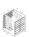
- FIG. 2 is a configuration diagram of the environmental test room 2 according to the present embodiment, and shows the configuration of the environmental test room 2 viewed from an obliquely upper direction.
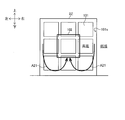
- FIG. 3 is an explanatory diagram of heat convection generated inside the environmental test chamber 2 according to the present embodiment, and shows a state inside the environmental test chamber 2 as viewed from the rear direction.
- FIG. 4 is a configuration diagram of the environmental test chamber 2Z of the comparative example, and shows the configuration of the environmental test chamber 2Z when viewed obliquely from above.
- FIG. 5 is an explanatory diagram of heat convection that occurs inside the environmental test chamber 2Z of the comparative example, and shows a state inside the environmental test chamber 2Z when viewed from the rear direction.
- the environmental test room 2 (see FIGS. 2 and 3) according to the present embodiment is a test room equipped with a curtain 103 (see FIGS. 2 and 3) described later.
- the environmental test chamber 2Z (FIGS. 4 and 5) of the comparative example is a test chamber that does not include the curtain 103 (FIGS. 2 and 3) described later.
- the environmental test chamber 2 has a hexahedral shape, and has a supply port 2in, a discharge port 2out, a flow path section 101, an installation section 102, and a curtain. And 103.
- the supply port 2 in is an opening to which conditioned air is supplied.
- the supply port 2 in is provided on the entire surface of an arbitrary surface in the environmental test chamber 2 having a hexahedral shape. Air-conditioned air having a substantially uniform predetermined wind speed and a substantially uniform predetermined temperature is supplied to the supply port 2 in.
- the outlet 2out is an opening through which conditioned air is discharged.
- the discharge port 2out is arranged on the entire surface of the environment test chamber 2 facing the supply port 2in.
- the flow path portion 101 is a portion through which the conditioned air inside the environmental test chamber 2 passes.
- the flow path portion 101 is arranged between the supply port 2in and the discharge port 2out.
- the installation unit 102 is a place where optical measurement devices such as a measurement target TG (test target) for optical measurement and a laser interferometer are installed.
- the installation portion 102 is arranged near the center of the flow path portion 101.
- the curtain 103 partitions the space in which the installation unit 102 is provided (hereinafter, referred to as “measurement target space”) from the space outside thereof, and rectifies the air flow of the conditioned air flowing in the flow path unit 101. It is a cloth-like rectifying member.
- two curtains 103 are arranged, one on each side of the installation unit 102, for a total of two curtains.
- the curtain 103 is arranged in the lateral direction between the side wall surface 101s of the flow path portion 101 and the installation portion 102 so as to extend in the depth direction.
- the curtain 103 is configured so that it can be deployed and stored in the direction of arrow A103. Therefore, the environmental test chamber 2 according to the present embodiment deploys (moves) or stores the curtain 103 when the measurement target TG or the optical measurement device is carried into the installation unit 102 provided near the center. Therefore, these can be easily carried in.
- the side wall surface 101s of the flow path unit 101 and the curtain 103 are arranged so as to be parallel to the air flow direction of the conditioned air flowing from the supply port 2in to the discharge port 2out.
- the entire surface of an arbitrary wall is made into the supply port 2 in which the conditioned air is blown out uniformly, and the side wall surface 101s of the flow path portion 101 and the curtain 103 rectify the conditioned air.
- the conditioned air supplied from the supply port 2in into the environmental test chamber 2 is rectified by the curtain 103 and proceeds almost straight toward the discharge port 2out, and the circulation flow path 6 (see FIG. 1) is discharged from the discharge port 2out. ) Is discharged (see arrow Aair).
- unintended heat transfer to the measurement target TG or the optical measurement device does not occur and the temperature of the measurement target TG or the optical measurement device does not change.
- the air flow of conditioned air can be controlled.
- the curtain 103 is preferably made of a radiation heat insulating material having a specular reflection surface F11 and a diffuse reflection surface F12 as a material.
- the specular reflection surface F11 is a surface having a specular reflection function (that is, a function of highly efficiently reflecting an image like a mirror).
- the diffuse reflection surface F12 is a surface having a diffuse reflection function (that is, a function of reflecting an image while diffusing it).
- a surface facing the side wall surface 101s of the flow path portion 101 (environmental test chamber 2) is a specular reflection surface F11, and a non-opposing surface (a surface on the installation portion 102 side) is a diffuse reflection surface F12.
- the environmental test chamber 2 can suppress the temperature of the space outside the curtain 103 from being transmitted to the space inside (the measurement target space).
- the temperature of the wall surface of the environmental test room 2 becomes lower than the temperature of the conditioned air. Due to the temperature difference, thermal convection may occur inside the environmental test chamber 2.
- the heat convection wraps around from the lower side of the environmental test chamber 2 and tries to enter the installation unit 102.
- the temperature of the heat convection is different from the temperature of the conditioned air. Therefore, if the thermal convection enters the installation unit 102, heat may be transferred from the thermal convection to the measurement target TG or the optical measurement device, and the temperature of the measurement target TG or the optical measurement device may change. .
- thermal convection may occur inside the environmental test chamber 2.
- the thermal convection tries to enter the installation unit 102 by wrapping around from the upper side of the environmental test chamber 2 in the opposite direction to the example shown in FIG. Also in this case, the temperature of the heat convection is different from the temperature of the conditioned air. Therefore, if the thermal convection enters the installation unit 102, heat may be transferred from the thermal convection to the measurement target TG or the optical measurement device, and the temperature of the measurement target TG or the optical measurement device may change. .
- the environmental test chamber 2 according to the present embodiment is provided with the curtain 103 inside as a member for suppressing the entry of thermal convection into the installation portion 102.
- the curtain 103 can prevent thermal convection from entering the installation unit 102 (see arrow A11). Therefore, in the environmental test chamber 2 according to the present embodiment, since the thermal convection does not reach the installation unit 102, the temperature of the measurement target TG or the optical measurement device installed in the installation unit 102 can be kept constant. As a result, the environmental test chamber 2 according to the present embodiment can enable highly accurate optical measurement under the atmospheric pressure environment.
- the environmental test chamber 2Z of the comparative example does not include the curtain 103 (FIGS. 2 and 3). Therefore, as shown in FIG. 5, in the environmental test chamber 2Z of the comparative example, thermal convection wraps around and tries to enter the installation unit 102 (see arrow A21). The temperature of the heat convection is different from the temperature of the conditioned air. Therefore, if the thermal convection enters the installation unit 102, heat may be transferred from the thermal convection to the measurement target TG or the optical measurement device, and the temperature of the measurement target TG or the optical measurement device may change. . Therefore, it is difficult for the environmental test chamber 2Z of the comparative example to perform highly accurate optical measurement under the atmospheric pressure environment. Therefore, the environmental test chamber 2 according to the present embodiment has a configuration suitable for highly accurate optical measurement under a pressure environment as compared with the environmental test chamber 2Z of the comparative example.
- FIG. 6 is a vertical cross-sectional view of the curtain 103.
- the curtain 103 has a structure in which a specular reflection film 501, a nonwoven fabric 502, and a diffuse reflection film 503 are laminated.
- the curtain 103 has a structure including two specular reflection films 501, two nonwoven fabrics 502, and one diffuse reflection film 503.
- the number of these members can be changed according to the operation.
- the number of specular reflection films 501 can be reduced to one, or conversely increased to three or more.
- the number of non-woven fabrics 502 can be reduced to one or conversely increased to three or more.
- the diffuse reflection film 503 can be increased to two or more.
- the above-mentioned specular reflection film 501 is a cloth material having a specular reflection function (that is, a function of reflecting an image with high efficiency like a mirror).
- the specular reflection film 501 can be composed of, for example, a polyester film having aluminum vapor-deposited on its surface.
- the specular reflection film 501 may be referred to as a “first type cloth material”.
- the above-mentioned non-woven fabric 502 is a spacer material for insertion.
- the non-woven fabric 502 preferably has a low thermal conductivity.
- the curtain 103 may have a structure in which another cloth-like member is provided as a spacer material instead of the nonwoven fabric 502.
- the above-mentioned diffuse reflection film 503 is a cloth material having a diffuse reflection function (that is, a function of reflecting an image while diffusing it).
- the diffuse reflection film 503 is preferably nonflammable and has an antistatic function.
- the diffuse reflection film 503 can be made of, for example, polyimide.
- the diffuse reflection film 503 may be referred to as a “second type cloth material”.
- the specular reflection film 501 (first type cloth material) constitutes the specular reflection surface F11
- the diffuse reflection film 503 (second type cloth material) constitutes the diffuse reflection surface F12.
- the curtain 103 is formed by stacking the specular reflection film 501, the non-woven fabric 502, and the diffuse reflection film 503, folding the ends thereof, and stitching them at an arbitrary position.
- Such a curtain 103 has a structure in which heat in the outer space is less likely to be transferred to the inner space (measuring space).
- FIG. 7A is a side view of the curtain 103.
- FIG. 7B is a front view of the curtain 103.
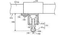
- FIG. 8A is a configuration diagram of the hanging member 151 for hanging the curtain 103 and the curtain rail 152.
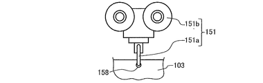
- FIG. 8B is a configuration diagram of the suspension member 151.
- FIG. 8C is a configuration diagram of a modified example of the suspension member 151.
- FIG. 8D is a configuration diagram of another modification of the suspension member 151.
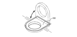
- FIG. 9A is a configuration diagram of a hook portion 161 for fixing the curtain 103 and a rubber band 162.
- FIG. 9B is a configuration diagram of the hook portion 161.
- FIG. 9C is a configuration diagram of the rubber band 162.
- the curtain 103 has a structure in which the upper side is hung by the hanging member 151. Further, as shown in FIGS. 7A and 7B, and FIGS. 9A to 9C, the curtain 103 may have a structure in which the lower side is fixed by the hook portion 161 or the like.
- the upper structure and the lower structure of the curtain 103 will be described.
- a curtain rail 152 into which a hanging member 151 for hanging the curtain 103 is fitted and slid.
- a supporting steel material 153 is attached to the ceiling panel 101top of the flow path portion 101 (environmental test chamber 2).
- a bracket 154 is attached to the supporting steel material 153 with bolts (or screws) 155.
- the curtain rail 152 is fixedly supported by the bracket 154.
- the curtain rail 152 supports the hanging member 151 so that it can travel freely.
- the hanging member 151 includes a ring-shaped support portion 151a that engages with an eyelet 158 provided near the upper end of the curtain 103, and a runner 151b that travels on the curtain rail 152. have.
- the eyelet 158 is a small hole provided in the curtain 103 for allowing the supporting portion 151a to pass therethrough.
- the eyelet 158 is preferably fitted with metal fittings around it.
- the upper end of the curtain 103 suspended by the suspending member 151 is arranged at a position separated from the ceiling surface 101t of the flow path unit 101 (environmental test chamber 2) by a gap 109t.
- the curtain rail 152 may be made of, for example, an aluminum alloy or the like.
- the support steel material 153, the bracket 154, the bolt (or screw) 155, and the like may be made of, for example, a stainless material.
- the supporting portion 151a of the suspension member 151 may be modified, for example, like the supporting portion 151aa shown in FIG. 8C or the supporting portion 151ab shown in FIG. 8D.
- the support portion 151aa shown in FIG. 8C has a structure in which a part can be opened and closed by a spring.
- the support portion 151ab shown in FIG. 8D has a structure in which a part of the support portion 151ab can be opened and closed by a removable screw and a shaft.
- a hook portion 161 for fixing the curtain 103 is provided on the floor surface 101b of the flow path portion 101 (environmental test chamber 2).
- An eyelet 159 is provided on the lower end of the curtain 103, and a hole is provided on the hook 161.
- the eyelet 159 is a small hole provided in the curtain 103 for passing the rubber band 162 therethrough.
- the eyelet 159 is preferably fitted with metal fittings around it.
- the lower end portion of the curtain 103 is fixed to the hook portion 161 by passing the rubber band 162 through the eyelet 159 of the curtain 103 and the hole portion of the hook portion 161. As shown in FIG.
- the hook portion 161 preferably has an embedded structure that is movable in the arrow direction. Thereby, the hook portion 161 can be pulled out from the floor surface 101b and used only when fixing the curtain 103, and can be stored on the floor surface 101b in other cases.
- FIG. 9C shows the configuration of the rubber band 162 when it is not used. As shown in FIG. 9A, the lower end portion of the curtain 103 fixed to the hook portion 161 by the rubber band 162 is arranged at a position separated from the floor surface 101b of the flow path portion 101 (environmental test chamber 2) by a gap 109b. There is.
- the curtain 103 expands in the vertical direction due to the weight of the curtain 103 itself, the weight of a metal fitting (not shown) attached to the curtain 103, the contracting force of the rubber band 162, and the like.
- the interval of the gap 109b changes according to the amount of vertical expansion of the curtain 103. Therefore, in the environment test chamber 2, the gap 109b can be closed with the curtain 103.
- the curtain 103 has a mirror reflection surface F11 on the surface facing the side wall surface 101s of the flow path portion 101 (environmental test chamber 2), and a non-facing surface (a surface on the installation portion 102 side). ) Is a diffuse reflection surface F12.
- the environmental test chamber 2 according to the present embodiment can suppress the temperature of the space outside the curtain 103 from being transmitted to the space inside (the measurement target space).
- the space to be measured (the space in which the installation unit 102 is provided) and the space outside it are partitioned, and the air flow of the conditioned air flowing in the flow path unit 101 is rectified.
- the rectifying member is composed of a cloth-shaped curtain 103.
- a curtain rail 152 is provided on the ceiling surface 101t of the environmental test chamber 2 according to the present embodiment, and an auxiliary curtain 505 is provided outside the curtain rail 152.
- the auxiliary curtain 505 is for suppressing the air flow between the space inside the curtain 103 (measuring space) and the space outside the curtain 103 via the gap 109t between the ceiling surface 101t and the curtain 103. It is a member.
- the auxiliary curtain 505 is wider than the gap 109t in the vertical and horizontal directions.
- the auxiliary curtain 505 is supported by the supporting member 504 on the ceiling surface 101t.
- the environment test chamber 2 according to the present embodiment can further stabilize the environment of the measurement target space (the space inside the curtain 103) by including the auxiliary curtain 505.
- FIG. 10 is an explanatory diagram showing an arrangement example of the measurement object TG in the environmental test room 2.
- the example shown in FIG. 10 is merely an example, and the type and arrangement position of the optical measuring instrument to be used can be appropriately changed according to the operation.
- a vibration isolator 21 is installed in the installation section 102 in the environmental test room 2, and the measurement object TG and the phase shift interferometer 401, are installed on the vibration isolator 21.
- a Michelson interferometer 402 is mounted.
- the phase shift interferometer 401 is mounted on, for example, the gantry 22a, and is arranged above the measurement target TG.
- the measurement object TG is placed on the pedestal 22b and arranged below the phase shift interferometer 401.
- a reflector 403 is attached to the gantry 22a, and a sensor head 404 is attached to the gantry 22b.
- the sensor head 404 is connected to the Michelson interferometer 402.
- the phase shift interferometer 401 irradiates the measurement target TG with light 405a to measure the surface shape of the measurement target TG.
- the Michelson interferometer 402 measures the displacement amount of the distance between the sensor head 404 and the reflector 403 with the light 405b emitted from the sensor head 404 toward the reflector 403 and reflected.
- the environment test chamber 2 according to the present embodiment is for suppressing variations in optical measurement.
- factors that affect the dispersion of the optical measurement there are factors shown in FIG. 11, for example.
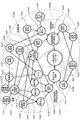
- FIG. 11 is an explanatory diagram showing factors that affect variations in optical measurement.
- factors affecting the optical measurement variation include the building (SYS1), the air conditioning equipment (SYS2), and the measurement target / optical measurement device (SYS4).
- SYS3 optical path space (air)
- SYS3 optical path space in the air conditioning equipment
- Factors of the building include installation environment temperature (Fa11), wall / floor temperature (wall / floor insulation performance) (Fa12), installation environment vibration (Fa13), floor vibration (Fa14), etc. .
- As factors of the air conditioning equipment (SYS2) equipment vibration (Fa21), air conditioning noise (Fa22), supply air temperature (Fa23), indoor air flow (Fa24), indoor pressure (atmospheric pressure) (Fa25), There are supply air humidity (Fa26), indoor humidity load (Fa27), and the like.
- the factors of the optical path space (air) (SYS3) are temperature diffusion (Fa31) due to airflow, temperature change (Fa32), pressure change (Fa33), humidity change (Fa34), and refractive index change (Fa34) of the optical path space. Fa35) and the like.
- Factors of the measurement object / optical measuring device (SYS4) include heat generation (Fa41), heat conduction (Fa42), radiant heat (Fa43), heat transfer (Fa44), and external force (Fa45) of the device.
- heat conduction means transfer of heat transmitted through a solid substance.
- radiant heat means transfer of heat radiated from the surface of the solid substance.
- heat transfer means the transfer of heat transferred through air.
- the environmental test chamber 2 suppresses (reduces) the factor of “temperature diffusion due to airflow (Fa31)” by the curtain 103.
- the environmental test room 2 according to the present embodiment can reduce the influence on the “variation of optical measurement (RS1)” by the following routes (a) and (b).
- B Wall / floor temperature (Fa12) ⁇ temperature diffusion by air flow (Fa31) ⁇ heat transfer (Fa44) ⁇ temperature change (Fa46) ⁇ shape dimension change (Fa47).
- the environmental test chamber 2 uses the curtain 103 to influence the factor of “radiant heat (Fa43)” on the factor of “temperature change (Fa46)” of the measurement target / optical measuring device (SYS4). Suppress (reduce). Thereby, the environmental test chamber 2 according to the present embodiment can reduce the influence on the “variation (RS1) of optical measurement” by the following route (c).
- the environment test chamber 2 can relatively strengthen (improve) the influence on the “variation of optical measurement (RS1)” by the following route (d). As a result, the temperature of the measurement target / optical measurement device (SYS4) can be stabilized.
- ⁇ Supplementary information on the environmental test room according to the present embodiment The following points are taken into consideration in the environmental test room 2 according to the present embodiment.
- the heat distribution of the entire space of the installation unit 102 be within ⁇ 0.5 ° C. Therefore, in the environmental test chamber 2 according to the present embodiment, it is preferable to use a material having a small heat capacity for the curtain 103.
- the heat capacity of the curtain 103 may be 2000 (J / m 2 ⁇ K) or less.
- the environmental test chamber 2 according to the present embodiment can quickly adapt the curtain 103 to the ambient temperature, so that the heat distribution in the measurement target space (the space in which the installation unit 102 is provided) has a low value. Can be easily converged to.
- the environmental test chamber 2 according to the present embodiment can easily keep the heat distribution of the entire space of the installation unit 102 within ⁇ 0.5 ° C. When the heat distribution of the entire space of the installation unit 102 falls within ⁇ 0.5 ° C., the heat distribution of the measurement target TG or the optical measurement device installed in the installation unit 102 is finally ⁇ 0.5. Fits within °C.
- the grounds for setting the heat capacity of the curtain 103 to 2000 (J / m 2 ⁇ K) or less are as follows. That is, assuming that the heat transfer coefficient of the curtain 103 is, for example, standard 5 (W / m 2 ⁇ K), if the heat capacity of the curtain 103 is 2000 (J / m 2 ⁇ K) or less, the time constant of the curtain 103 is constant. Is 400 (s) or less. This is sufficiently (for example, about one digit) smaller than the time constant required for the measurement target TG and the optical measurement device used for the measurement when the measurement target TG is an optical device used for astronomical observation.
- the heat capacity of the curtain 103 is 2000 (J / m 2 ⁇ K) or less, the curtain 103 approaches the temperature of the conditioned air faster than the measurement target TG or the optical measurement device, and does not hinder the measurement. Therefore, the heat capacity of the curtain 103 is preferably 2000 (J / m 2 ⁇ K) or less.
- the curtain 103 is preferably made of a radiation heat insulating material having a specular reflection surface F11 and a diffuse reflection surface F12 as a material.
- the curtain 103 is preferably installed such that the surface facing the side wall surface 101s of the flow path portion 101 (environmental test chamber 2) is the specular reflection surface F11 and the non-opposing surface is the diffuse reflection surface F12.
- the environmental test chamber 2 according to the present embodiment can suppress heat transfer from the side wall surface 101s to the measurement target TG placed on the installation unit 102 due to radiant heat.
- the temperature inside the curtain 103 can be made substantially the same.
- the environment test chamber 2 according to the present embodiment can easily make the heat distribution in the measurement target space converge to a small value.
- the environmental test chamber 2 according to the present embodiment can further facilitate the heat distribution of the entire space of the installation unit 102 to be within ⁇ 0.5 ° C.
- the curtain 103 is supported by the ceiling surface 101t and the lower end 103b of the flow path portion 101 only at arbitrarily provided support points, and is not supported at locations other than the support points. It is structured. That is, as shown in FIG. 3, in the environment test chamber 2 according to the present embodiment, in a place other than the supporting place, a slight gap is provided between the upper end portion 103t of the curtain 103 and the ceiling surface 101t of the flow path portion 101. The structure is provided with 109t.
- the environmental test chamber 2 has a structure in which a slight gap 109b is provided between the lower end portion 103b of the curtain 103 and the floor surface 101b of the flow path portion 101 at a place other than the supporting place. Has become. This is because the contact area of the curtain 103 with respect to the ceiling surface 101t and the floor surface 101b of the flow path unit 101 (environmental test chamber 2) is reduced, and the amount of heat conduction transferred from the flow path unit 101 (environmental test chamber 2) to the curtain 103. This is because the temperature of the curtain 103 is suppressed as much as possible.
- the curtain 103 is relatively loosely fixed so that it can be deployed and stored in the direction of arrow A103 (see FIG. 2).
- the sizes of the gap 109t and the gap 109b are preferably about 1% of the height of the internal space of the environmental test chamber 2, respectively. Therefore, the environmental test chamber 2 has a structure in which the curtain 103 having a height of about 98% with respect to the height of the internal space of the environmental test chamber 2 is provided above and below the gap 109t and the gap 109b. Good.
- the width, height, and depth of the internal space of the environmental test chamber 2 are, for example, about several meters (m) to ten and several meters (m), respectively.
- the temperature and humidity of the conditioned air passing through the installation unit 102 are stabilized to stabilize the refractive index of the conditioned air, and the measurement target TG. It is important to stabilize the temperature of 1 to suppress the deformation of the measurement target TG due to thermal expansion. Regarding these, the temperature and humidity of the conditioned air supplied from the outside of the environmental test chamber 2 can be stabilized by the heaters 51 and 54, the heat storage body 55 and the like (see FIG. 1).
- the temperature and humidity of the conditioned air passing through the installation unit 102 are measured when the temperature of the conditioned air is diffused from the surrounding side wall surface 101s or the floor surface, or when there is a temperature difference between the measurement object TG and the conditioned air. It changes under the influence of temperature diffusion from TG. Therefore, in order to stabilize the temperature of the installation unit 102, the environment test chamber 2 not only controls the speed of the conditioned air, but also prevents temperature diffusion from the surrounding environment such as the side wall surface 101s and the floor surface. That is, it is preferable to suppress the temperature difference between the measurement target TG and the conditioned air.
- the temperature of the measuring object TG is controlled by heat transfer with the conditioned air controlled to a constant temperature.
- the leveling method shall be adopted. This method is effective when there is no calorific value from the measurement target TG or when it is extremely small. Further, this method has the advantage that the temperature is surely stabilized with the passage of time, that the temperature distribution in the measurement target TG can be reduced unlike the local heating / cooling, and the measurement target TG For example, the temperature difference between the conditioned air and the conditioned air can be reduced, and the temperature of the conditioned air passing through the installation unit 102 can be stabilized.
- the environment test chamber 2 reduces the velocity component in the vertical direction with respect to the side wall surface 101s and the floor surface.
- the velocity of the airflow in the road portion 101 is set.
- the environment test chamber 2 has a supply port 2 in provided on the entire surface of an arbitrary surface, and a discharge port 2out provided on the entire surface of the opposing surface of the supply port 2 in.
- Air-conditioned air having a substantially uniform predetermined wind speed and a substantially uniform predetermined temperature is supplied to the supply port 2 in.
- the airflow of the conditioned air travels in parallel to the side wall surface 101s of the flow path portion 101 formed inside the environment test chamber 2 and the floor surface.
- an air flow in approximately one direction is formed in the flow path portion 101. Since this airflow has a small velocity component in the vertical direction with respect to the side wall surface or floor surface where the supply port 2in and the discharge port 2out are not provided, the convection diffusion of temperature from the side wall surface and the floor surface is small. Further, this air flow hits the measuring object uniformly and does not stay around the measuring object TG very much. This air flow uniformly transfers heat to the entire measurement target TG, and is effective in leveling the temperature over the entire measurement target TG.
- the environmental test chamber 2 includes a curtain 103 parallel to the air flow direction between the side wall surface 101s and the installation portion 102 provided near the center of the environmental test chamber 2.
- the curtain 103 can prevent thermal convection from entering the installation portion 102. it can.
- the curtain 103 prevents the air flow around the measurement target TG from diffusing away from the measurement target TG, and heats the measurement target TG and the conditioned air. A function that facilitates transmission can be obtained.
- the curtain 103 has a temperature close to the temperature of the conditioned air. Therefore, it is preferable that heat conduction from the wall or floor to the curtain 103 is small and the heat capacity of the curtain 103 is small.
- the temperature of the measurement target TG is affected by the radiant heat from the wall surface or floor surface of the environmental test room 2. Therefore, it is desirable that the curtain 103 is made of a radiation heat insulating material having the mirror surface F11 on the wall surface side of the environmental test chamber 2.
- the curtain 103 is made of a radiation heat insulating material having the mirror surface F11 on the wall surface side of the environmental test chamber 2.
- the surface facing the wall surface of the environmental test chamber 2 be a specular reflection surface F11.
- the surface of the curtain 103 on the measurement target TG side is preferably the diffuse reflection surface F12.
- the environment test chamber 2 according to the present embodiment can stabilize the air refractive index of the measurement space and the temperature of the measurement object, and the installation environment of the measurement object capable of highly accurate optical measurement under the atmospheric pressure environment. Can be provided.
- the environment test chamber 2 can perform highly accurate optical measurement under the atmospheric pressure environment. Further, according to the environment test chamber 2 of the present embodiment, when the measurement target TG or the optical measuring device is carried into the installation unit 102, the cloth-like curtain 103 is unfolded (moved) or stored. Therefore, these can be easily carried in.
- the present invention is not limited to the above-described embodiment, but includes various modifications.
- the above-described embodiments have been described in detail in order to explain the present invention in an easy-to-understand manner, and are not necessarily limited to those having all the configurations described.
Landscapes
- Life Sciences & Earth Sciences (AREA)
- Engineering & Computer Science (AREA)
- Chemical & Material Sciences (AREA)
- Physics & Mathematics (AREA)
- Analytical Chemistry (AREA)
- Mechanical Engineering (AREA)
- Biodiversity & Conservation Biology (AREA)
- Ecology (AREA)
- Environmental & Geological Engineering (AREA)
- Environmental Sciences (AREA)
- Combustion & Propulsion (AREA)
- Health & Medical Sciences (AREA)
- General Engineering & Computer Science (AREA)
- Biochemistry (AREA)
- General Health & Medical Sciences (AREA)
- General Physics & Mathematics (AREA)
- Immunology (AREA)
- Pathology (AREA)
- Testing Resistance To Weather, Investigating Materials By Mechanical Methods (AREA)
- Duct Arrangements (AREA)
Abstract
環境試験室(2)は、均一風速で均一温度の空調空気が供給される供給口(2in)と、供給口に対向配置され、空調空気が排出される排出口(2out)と、供給口と排出口との間に配置され、空調空気が通る流路部(101)と、流路部の中央付近に配置され、光学測定の測定対象物が設置される設置部(102)と、流路部の側壁面(101s)と設置部との間に配置され、空調空気の気流を整流する整流部材と、を備えている。流路部の側壁面と整流部材は、供給口から排出口に向かって流れる空調空気の気流方向と平行になるように配置されており、設置部側の面に拡散反射面を有する。
Description
本発明は、環境試験室、及び、それに用いる整流部材に関する。
例えば、天文観測のための光学機器は、レンズの表面形状や構造体寸法についてナノメートル(nm)オーダーの高精度な測定が必要である。その測定方法として、レーザー干渉計等の光学測定機器による光学測定が一般に用いられる。
しかしながら、大気圧環境下でレーザー干渉計を使用する場合に、大気の温度や湿度、圧力等のゆらぎによるばらつきが測定に影響を与えることが知られている(例えば、非特許文献1参照)。そのため、高精度な光学測定を行う際は、光路空間を真空にして、大気の温度や湿度、圧力等のゆらぎの影響を無くした状態で測定することが一般的である(例えば、非特許文献2参照)。
また、大気圧環境下で高精度な測定を行うために、空調制御によって測定環境を安定化させることが提案されている(例えば、特許文献1参照)。光学機器の測定では、例えば特許文献1に記載された局所空間を環境試験室とし、測定対象物(試験対象)や光学測定機器を環境試験室に設置して光学測定を行う。
赤津利雄著「精密位置決め用変位センサーの現状と問題点」、掲載誌「光学」、第22巻第6号、掲載ページ329~334、1993年6月
寺田聡一著「長さ標準:レーザー測長における真空および大気の影響」、掲載誌「Journal of the Vacuum Society of Japan」、第52巻第6号、掲載ページ347~350、2009年7月15日
大気(空気)の温度や湿度、圧力等にゆらぎがあると、空気の屈折率が変動して、光学測定のばらつきが発生する可能性がある。従来の環境試験室は、高精度な光学測定を行うために、大気の温度や湿度、圧力等のゆらぎを抑制すること(つまり、大気を安定化させること)を考慮するものであった。しかしながら、本発明の発明者は、大気の温度や湿度、圧力等でなく、環境試験室内に設置される測定対象物(試験対象)や光学測定機器に温度のゆらぎがあると、これらの表面形状や構造体寸法が変動して、光学測定のばらつきが発生する可能性があることを解明した。そして、従来の環境試験室は、測定対象物や光学測定機器の温度のゆらぎを抑制することを考慮していないものであった。このような従来の環境試験室は、大気圧環境下で高精度な光学測定を行うことが困難であった。なお、測定対象物や光学測定機器の温度のゆらぎは、例えば、環境試験室の内部の熱対流からの熱伝達や、壁や床からの放射熱によって発生する。
例えば、環境試験室の周囲の温度が空調空気の設定温度より低い場合に、環境試験室の壁面の温度は空調空気の温度より低くなる。また、例えば、環境試験室の周囲の温度が空調空気の設定温度より高い場合に、環境試験室の壁面の温度は空調空気の温度より高くなる。測定対象物や光学測定機器は、空調空気の設定温度と同じ温度になることが期待されるが、前記の状況では測定対象物や光学測定機器と環境試験室の壁面の間には温度差が生じ、測定対象物や光学測定機器と環境試験室の壁面の間で放射熱による熱の授受が発生する。その結果、環境試験室周囲の温度変化によって測定対象物や光学測定機器の温度が変化するため、光学測定のばらつきが増大する可能性があった。従来の環境試験室は、測定対象物や光学測定機器の表面形状や構造体寸法が変動しないように、測定対象物や光学測定機器の温度を安定化させることについては考慮されていない。そのため、このような従来の環境試験室は、大気圧環境下で高精度な光学測定を行うことが困難であった。
本発明は、前記した課題を解決するためになされたものであり、大気圧環境下で高精度な光学測定を可能にすることを主な目的とする。
前記目的を達成するため、本発明は、環境試験室であって、所定風速で所定温度の空調空気が供給される供給口と、前記供給口に対向配置され、前記空調空気が排出される排出口と、前記供給口と前記排出口との間に配置され、前記空調空気が通る流路部と、前記流路部の中央付近に配置され、光学測定の測定対象物が設置される設置部と、前記流路部の側壁面と前記設置部との間に配置され、前記空調空気の気流を整流する整流部材と、を備え、前記流路部の側壁面と前記整流部材は、前記供給口から前記排出口に向かって流れる前記空調空気の気流方向と平行になるように配置されており、設置部側の面に拡散反射面を有する構成とする。
前記整流部材は、展開及び収納が可能な布状のカーテンで構成されていてもよい。
その他の手段は、後記する。
前記整流部材は、展開及び収納が可能な布状のカーテンで構成されていてもよい。
その他の手段は、後記する。
本発明によれば、大気圧環境下で高精度な光学測定を行うことができる。
以下、図面を参照して、本発明の実施の形態(以下、「本実施形態」と称する)について詳細に説明する。なお、各図は、本発明を十分に理解できる程度に、概略的に示してあるに過ぎない。よって、本発明は、図示例のみに限定されるものではない。また、各図において、共通する構成要素や同様な構成要素については、同一の符号を付し、それらの重複する説明を省略する。
[実施形態]
<環境試験室を含む空気調和システム全体の構成>
以下、図1を参照して、本実施形態に係る環境試験室を含む空気調和システム全体の構成について説明する。図1は、本実施形態に係る環境試験室を含む空気調和システム全体の構成図である。
<環境試験室を含む空気調和システム全体の構成>
以下、図1を参照して、本実施形態に係る環境試験室を含む空気調和システム全体の構成について説明する。図1は、本実施形態に係る環境試験室を含む空気調和システム全体の構成図である。
図1に示すように、空気調和システム1は、除湿部3、乾燥空気調温部4、乾燥空気加熱部5、循環流路6、送風機41、ヒータ51,54、蓄熱体55等を備えている。空気調和システム1は、循環流路6を介して環境試験室2の排出口2outから排出される空気を空気調和して環境試験室2の供給口2inに戻し、システム内で空調空気を循環させる。
除湿部3は、デシカント空調機30等の除湿機を備え、環境試験室2から排出される空気に外気を混合した空気を除湿して得られる乾燥空気を乾燥空気調温部4へ送気する。乾燥空気調温部4は、除湿部3から送気される乾燥空気を環境試験室2の内部の設定空気温度よりもやや低い温度に調温し、乾燥空気加熱部5へ送気する。乾燥空気加熱部5は、環境試験室2の内部の設定空気温度まで加熱して環境試験室2内に送気する。
ここで、環境試験室2内は、断熱パネル等からなる外壁によって外気から遮断されている。環境試験室2には、空気調和システム1で空気調和された空気のみが供給される。そして、環境試験室2内の中央付近には、光学測定の測定対象物やレーザー干渉計等の光学測定機器を設置する設置部102が設けられている。設置部102には、防振架台21等が設置されており、その防振架台21上には、測定対象物や光学測定機器が載置される。環境試験室2の詳細については、「環境試験室の構成」の章で説明する。
空気調和システム1の乾燥空気加熱部5は、通常、環境試験室2の特定の側面全体に分布して設置され、乾燥空気加熱部5から送気された空気は、環境試験室2の中を、乾燥空気加熱部5を設置した側面からそれに対向する側面に向かって流れ、その大半が除湿部3側へ排出され、空気調和システム1内を還流するとともに、一部が外気へ排出される。なお、外気への排気ダクトには、その排出量を調節するバルブ23が設けられている。
除湿部3は、デシカント空調機30を主な構成要素として備え、環境試験室2から排出された空気及び外気がそれぞれクーラ31,34で除湿に適した温度に冷却された上で混合されて、デシカント空調機30に供給される。クーラ31,34の出口には、それぞれ温度センサ32,35が設けられており、制御装置(図中ではPIDと記載)33,36は、温度センサ32,35により得られる温度が所定の除湿に適した温度となるようにクーラ31,34をそれぞれ制御する。
デシカント空調機30に供給される空気すなわち除湿対象の空気をクーラ31,34により冷却することは、除湿対象の空気を除湿に適した温度にするというだけでなく、プレ除湿をするという意味を有している。とくに、外気は湿度が高いので、クーラ34でプレ除湿をしておくことにより、デシカント空調機30での除湿の負担を軽減することができる。
なお、図1では、環境試験室2から排出された空気及び外気は、それぞれクーラ31,34で冷却された後に混合されているが、環境試験室2から排出された空気及び外気を先に混合して、1つのクーラで冷却するようにしてもよい。
デシカント空調機30に供給された空気(除湿対象の空気)は、送風機302により送気され、水分吸着物質が保持されたデシカントロータ301の中を通過、除湿される。ここで、デシカントロータ301の中に保持される水分吸着物質としては、高分子吸着剤、シリカゲル、ゼオライト等、低温時に水分を吸着し、高温時に水分を放出する高温再生型の水分吸着物質が用いられる。
デシカントロータ301は、円筒形状をしており、円筒の軸を中心にして、例えば図1に示す矢印の方向に回転する。ここで、除湿対象の空気の大半は、回転するデシカントロータ301の領域Aの部分を通過、除湿され、乾燥空気となって乾燥空気調温部4側へ送気される。また、除湿対象の空気の一部は、デシカントロータ301の領域Cの部分を通過し、ヒータ304により加熱された後、再びデシカントロータ301に戻り領域Bの部分を通過する。このとき、デシカントロータ301の領域Bの部分に保持されている水分吸着物質は、加熱された空気に曝されることとなるので、水分吸着能力を回復する。一方で、領域Bの部分を通過した空気は、水分を多く含むこととなるので、送風機303を介して、除湿部3(空気調和システム1)の外に排気される。
デシカントロータ301は、領域A→領域B→領域C→領域A→…の方向に回転する。ここで、領域Aの部分は、クーラ31,34により冷却された除湿対象の空気が通過し、領域Bの部分は、ヒータ304により加熱された空気が通過する。そのため、デシカントロータ301の回転とともに、その中に保持されている水分吸着物質は、領域Aの部分で水分を吸着するが、領域Bの部分で吸着していた水分を放出し、水分吸着能力を回復する。
また、冷却された除湿対象の空気の一部は、領域Cの部分を通過する。このとき、領域Bの部分で加熱された水分吸着物質は、冷却されるとともに、領域Cの部分を通過した空気は加熱される。したがって、ヒータ304における加熱に必要なエネルギーを節減することができる。
デシカントロータ301の領域Aの部分を通過した空気は、温度が上昇する。そこで、領域Aの部分を通過した空気は、クーラ37により環境試験室2から排出された空気とほぼ同程度の温度まで冷却される。このとき、クーラ37の出口には温度センサ38が設けられており、クーラ37を通過した空気は、制御装置39により一定温度を保つように制御される。
ところで、本実施形態では、環境試験室2から排出される空気のすべてが除湿部3へ供給されるのではなく、その一部は、バイパスダクト15を通過、すなわち、除湿部3をバイパスして乾燥空気調温部4へ流れるようにされている。こうすることにより、環境試験室2から排出される空気のうち、環境試験室2で発生した湿度上昇分を除去するのに必要な空気量のみを除湿部3へ流すことが可能になる。少なくとも空気調和システム1の作動が開始され一定の時間が経過した後は、環境試験室2で発生する湿度の上昇はわずかとなる。したがって、環境試験室2から排出される空気のうち一部をバイパスダクト15側へ流すことにより、デシカントロータ301の除湿負担を低減することができ、さらには、デシカントロータ301の小型化にもつながる。
なお、除湿部3へ供給される空気量及び除湿部3をバイパスさせる空気量は、それぞれバルブ11,13の開度制御によって調整することができる。また、当然ながら、バイパスダクト15を設けないで、環境試験室2から排出される空気をすべて除湿部3へ供給するものとしてもよい。
なお、デシカント空調機30から排出される空気の湿度は、デシカントロータ301の領域Bの部分の温度、つまり、ヒータ304の加熱強度、デシカントロータ301の回転速度、送風機302の風量等の調整により適宜設定することができる。
また、本実施形態では、除湿部3は、デシカント空調機30により除湿をするものとしたが、除湿手段は、デシカント空調機30に限定されず、冷却と過熱を繰り返す方法等で除湿するものであってもよい。
次に、乾燥空気調温部4は、冷水を冷媒とするクーラ42、チラー43、冷却された冷水を加熱するヒータ48等を含んで構成される。除湿部3から送気されてくる乾燥空気は、クーラ42によって環境試験室2の内部の設定空気温度よりも低い温度に調温された上、乾燥空気加熱部5へ送気される。
ここで、クーラ42は、冷却ダクト40内に設けられ、冷媒である冷水(以下、冷媒水という)が通流するコイル状の配管により構成される。このとき、冷水コイルを通流する冷媒水は、ヒータ48で加熱されることにより、所定の冷媒水の目標温度に調温される。そして、送風機41を介して除湿部3から送気されてくる乾燥空気は、この冷水コイルに接触することによって冷却され、所定の乾燥空気の目標温度(環境試験室2の内部の設定空気温度よりもやや低い温度)に調温される。
ここで、冷媒水を通流させる配管の途中には、ヒータ48の他にタンク47が設けられている。タンク47は、冷媒水を一時貯留することにより、この冷媒水の温度の安定させる役割を果たす。
したがって、ヒータ48には、温度変動の小さい冷媒水が供給される。そして、その温度変動の小さい冷媒水は、制御装置61,62で制御されたヒータ48によって加熱され、クーラ42に送水される。このとき、制御装置61は、冷却ダクト40の出口に設けられた温度センサ63から得られる空気温度を、予め設定された目標空気温度と比較し、その差分量に基づいてヒータ48の出口における冷媒水の目標温度を演算する。さらに、制御装置62は、ヒータ48の出口に設けられた温度センサ49から得られる冷媒水の温度を、制御装置61で演算された冷媒水の目標温度と比較し、その差分量に基づいてヒータ48の発熱強度を制御する。
乾燥空気加熱部5は、ヒータ51,54、蓄熱体55、温度センサ52,56、制御装置53,57等を備えて構成される。乾燥空気調温部4から供給される乾燥空気は、ヒータ51を通過することで所定の温度に加熱され、さらに、環境試験室2の側面に設けられたヒータ54及び蓄熱体55を通過することで、予め設定された環境試験室2内の設定空気温度まで加熱される。
ここで、ヒータ51の加熱強度は、その出口に設けられた温度センサ52により得られる温度が一定となるように制御装置53によって制御される。同様に、ヒータ54の加熱強度は、蓄熱体55からの出口である環境試験室2の天井部に設けられた温度センサ52により得られる温度が環境試験室2内の設定空気温度と同じになるように制御装置57によって制御される。
環境試験室2の供給口2inには、ヒータ54及び蓄熱体55が複数セット設けられている。したがって、環境試験室2内へは、一定の温度に保たれた乾燥空気がほぼ均一に供給されるので、環境試験室2内の空気温度も均一化される。
ヒータ54の下流側に設けられる蓄熱体55は、空気の通路となる多数の孔部を備えた多孔通路部材によって構成される。蓄熱体55は、孔部を通過する空気の温度が自身の温度よりも高ければ、熱を吸収し、低ければ、熱を放出する。そのため、蓄熱体55は、温度が変動しにくいものが好ましく、通常は、熱容量が大きい材料、また熱伝導率がよい材料(例えば、銅やアルミニウム等の金属)を用いて構成される。したがって、蓄熱体55の孔部を通過して環境試験室2内に送気される乾燥空気の温度変動を効果的に抑制することができる。
<環境試験室の構成>
以下、まず、図2及び図3を参照して、本実施形態に係る環境試験室2の構成について説明し、次に、図4及び図5を参照して、比較例の環境試験室2Zの構成について説明する。
以下、まず、図2及び図3を参照して、本実施形態に係る環境試験室2の構成について説明し、次に、図4及び図5を参照して、比較例の環境試験室2Zの構成について説明する。
図2は、本実施形態に係る環境試験室2の構成図であり、斜め上方向から見た環境試験室2の構成を示している。図3は、本実施形態に係る環境試験室2の内部で発生する熱対流の説明図であり、背面方向から見た環境試験室2の内部の状況を示している。一方、図4は、比較例の環境試験室2Zの構成図であり、斜め上方向から見た環境試験室2Zの構成を示している。図5は、比較例の環境試験室2Zの内部で発生する熱対流の説明図であり、背面方向から見た環境試験室2Zの内部の状況を示している。
本実施形態に係る環境試験室2(図2及び図3参照)は、後記するカーテン103(図2及び図3参照)を備えた試験室である。これに対して、比較例の環境試験室2Z(図4及び図5)は、後記するカーテン103(図2及び図3)を備えていない試験室である。
図2に示すように、本実施形態に係る環境試験室2は、6面体状の形状を呈しており、供給口2inと、排出口2outと、流路部101と、設置部102と、カーテン103と、を備えている。
供給口2inは、空調空気が供給される開口部である。供給口2inは、6面体状の形状を呈する環境試験室2における任意の面の全面に設けられている。供給口2inには、ほぼ均一な所定風速でかつほぼ均一な所定温度の空調空気が供給される。排出口2outは、空調空気が排出される開口部である。排出口2outは、環境試験室2における供給口2inに対向する面の全面に配置されている。流路部101は、環境試験室2の内部の空調空気が通る部位である。流路部101は、供給口2inと排出口2outとの間に配置されている。設置部102は、光学測定の測定対象物TG(試験対象)やレーザー干渉計等の光学測定機器が設置される場所である。設置部102は、流路部101の中央付近に配置されている。
カーテン103は、設置部102が設けられている空間(以下、「測定対象空間」と称する)とその外側の空間との間を仕切るとともに、流路部101内を流れる空調空気の気流を整流する布状の整流部材である。本実施形態では、カーテン103は、設置部102の両横に1枚ずつ、合計2枚配置されている。カーテン103は、奥行き方向に延在するように、横方向において流路部101の側壁面101sと設置部102との間に配置されている。
カーテン103は、矢印A103の方向に展開及び収納が可能な構成になっている。そのため、本実施形態に係る環境試験室2は、中央付近に設けられた設置部102に測定対象物TGや光学測定機器を搬入する際に、カーテン103を展開(移動)したり収納したりすることで、これらを容易に搬入することができる。
流路部101の側壁面101sとカーテン103は、供給口2inから排出口2outに向かって流れる空調空気の気流方向と平行になるように配置されている。このような本実施形態に係る環境試験室2は、任意の壁の全面を均一に空調空気を吹き出す供給口2inとし、流路部101の側壁面101sとカーテン103とで空調空気を整流する。これにより、供給口2inから環境試験室2内に供給された空調空気は、カーテン103で整流されて排出口2outに向かってほぼ真っ直ぐに進行し、排出口2outから循環流路6(図1参照)に排出される(矢印Aair参照)。このような本実施形態に係る環境試験室2は、測定対象物TGや光学測定機器への意図せぬ熱の伝達が発生して、測定対象物TGや光学測定機器の温度が変動しないように、空調空気の気流をコントロールすることができる。
図3に示すように、カーテン103は、素材として、鏡面反射面F11と拡散反射面F12とを有する輻射断熱材が用いられているとよい。鏡面反射面F11は、鏡面反射機能(つまり、鏡のように画像を高効率に反射する機能)を有する面である。拡散反射面F12は、拡散反射機能(つまり、拡散させながら画像を反射する機能)を有する面である。そして、カーテン103は、流路部101(環境試験室2)の側壁面101sとの対向面が鏡面反射面F11となり、非対向面(設置部102側の面)が拡散反射面F12となるように、設置されるとよい。これにより、本実施形態に係る環境試験室2は、カーテン103よりも外側の空間の温度がその内側の空間(測定対象空間)に伝達されることを抑制することができる。
ところで、例えば、図3に示すように、環境試験室2の周囲の温度が空調空気の設定温度より低い場合に、環境試験室2の壁面の温度は空調空気の温度より低くなる。その温度差によって、環境試験室2の内部で熱対流が発生する可能性がある。その熱対流は、環境試験室2の下側から回り込んで設置部102に進入しようとする。そして、その熱対流の温度は、空調空気の温度と違っている。そのため、熱対流が設置部102に進入してしまうと、熱対流から測定対象物TGや光学測定機器に熱が伝達して、測定対象物TGや光学測定機器の温度が変動する可能性がある。
なお、例えば、図3に示す例とは逆に、環境試験室2の周囲の温度が空調空気の設定温度より高い場合に、環境試験室2の壁面の温度は空調空気の温度より高くなる。その温度差によっても、環境試験室2の内部で熱対流が発生する可能性がある。その熱対流は、図3に示す例とは逆向きに、環境試験室2の上側から回り込んで設置部102に進入しようとする。この場合も、熱対流の温度は、空調空気の温度と違っている。そのため、熱対流が設置部102に進入してしまうと、熱対流から測定対象物TGや光学測定機器に熱が伝達して、測定対象物TGや光学測定機器の温度が変動する可能性がある。
そこで、本実施形態に係る環境試験室2は、内部に、その設置部102への熱対流の侵入を抑制するための部材として、カーテン103を備えている。このような本実施形態に係る環境試験室2は、カーテン103で熱対流が設置部102に進入することを抑制することができる(矢印A11参照)。したがって、本実施形態に係る環境試験室2は、設置部102に熱対流が到達しないため、設置部102に設置された測定対象物TGや光学測定機器の温度を一定に保つことができる。その結果、本実施形態に係る環境試験室2は、大気圧環境下で高精度な光学測定を可能にすることができる。
これに対して、図4及び図5に示すように、比較例の環境試験室2Zは、カーテン103(図2及び図3)を備えていない。そのため、図5に示すように、比較例の環境試験室2Zでは、熱対流が回り込んで設置部102に進入しようとする(矢印A21参照)。その熱対流の温度は、空調空気の温度と違っている。そのため、熱対流が設置部102に進入してしまうと、熱対流から測定対象物TGや光学測定機器に熱が伝達して、測定対象物TGや光学測定機器の温度が変動する可能性がある。したがって、比較例の環境試験室2Zは、大気圧環境下で高精度な光学測定を行うことが困難である。よって、本実施形態に係る環境試験室2は、比較例の環境試験室2Zよりも気圧環境下で高精度な光学測定に適した構成になっている。
<カーテンの構成>
以下、図6を参照して、カーテン103の構成について説明する。図6は、カーテン103の縦断面図である。
以下、図6を参照して、カーテン103の構成について説明する。図6は、カーテン103の縦断面図である。
図6に示すように、カーテン103は、鏡面反射フィルム501と、不織布502と、拡散反射フィルム503とが積層された構造になっている。なお、図6に示す例では、カーテン103は、2枚の鏡面反射フィルム501と、2枚の不織布502と、1枚の拡散反射フィルム503を備えた構造になっている。しかしながら、これらの部材の枚数は、運用に応じて変更することができる。例えば、鏡面反射フィルム501の枚数は、1枚に減らしたり、逆に3枚以上に増やしたりすることができる。同様に、不織布502の枚数も、1枚に減らしたり、逆に3枚以上に増やしたりすることができる。また、拡散反射フィルム503は、2枚以上に増やすことができる。
前記した鏡面反射フィルム501は、鏡面反射機能(つまり、鏡のように画像を高効率に反射する機能)を有する布材である。鏡面反射フィルム501は、例えば、表面にアルミニウムが蒸着されたポリエステルフィルムで構成することができる。以下、鏡面反射フィルム501を「第1種布材」と称する場合がある。
前記した不織布502は、間挿用のスペーサ材である。不織布502は、好ましくは、熱伝導率の低いものであるとよい。なお、カーテン103は、不織布502の代わりに、別の布状の部材をスペーサ材として備える構造にすることができる。
前記した拡散反射フィルム503は、拡散反射機能(つまり、拡散させながら画像を反射する機能)を有する布材である。拡散反射フィルム503は、不燃性で、かつ、帯電防止機能を有するとよい。拡散反射フィルム503は、例えば、ポリイミド等で構成することができる。以下、拡散反射フィルム503を「第2種布材」と称する場合がある。
カーテン103は、鏡面反射フィルム501(第1種布材)で鏡面反射面F11を構成し、また、拡散反射フィルム503(第2種布材)で拡散反射面F12を構成している。カーテン103は、鏡面反射フィルム501と不織布502と拡散反射フィルム503が積層状態になっているとともに、その端部が折り返されており、任意の箇所で縫合されることで形成されている。このようなカーテン103は、外側の空間の熱が内側の空間(測定対象空間)に伝達させ難い構造になっている。
<カーテンの配置例>
以下、図7A及び図7B、図8A乃至図8D、並びに、図9A乃至図9Cを参照して、カーテン103の配置例について説明する。図7Aは、カーテン103の側面図である。図7Bは、カーテン103の正面図である。図8Aは、カーテン103を吊るす吊下げ部材151とカーテンレール152の構成図である。図8Bは、吊下げ部材151の構成図である。図8Cは、吊下げ部材151の変形例の構成図である。図8Dは、吊下げ部材151の別の変形例の構成図である。図9Aは、カーテン103を固定するフック部161とゴムバンド162の構成図である。図9Bは、フック部161の構成図である。図9Cは、ゴムバンド162の構成図である。
以下、図7A及び図7B、図8A乃至図8D、並びに、図9A乃至図9Cを参照して、カーテン103の配置例について説明する。図7Aは、カーテン103の側面図である。図7Bは、カーテン103の正面図である。図8Aは、カーテン103を吊るす吊下げ部材151とカーテンレール152の構成図である。図8Bは、吊下げ部材151の構成図である。図8Cは、吊下げ部材151の変形例の構成図である。図8Dは、吊下げ部材151の別の変形例の構成図である。図9Aは、カーテン103を固定するフック部161とゴムバンド162の構成図である。図9Bは、フック部161の構成図である。図9Cは、ゴムバンド162の構成図である。
図7A及び図7B、並びに、図8A乃至図8Dに示すように、カーテン103は、上側が吊下げ部材151で吊下げられた構造になっているとよい。また、図7A及び図7B、並びに、図9A乃至図9Cに示すように、カーテン103は、下側がフック部161等で固定された構造になっているとよい。以下、カーテン103の上側の構造と下側の構造の詳細について説明する。
図7A及び図7B、並びに、図8Aに示すように、流路部101(環境試験室2)の天井面101tには、カーテン103を吊るす吊下げ部材151をはめ込んで滑らせるカーテンレール152が設けられている。流路部101(環境試験室2)の天井パネル101topには、支持鋼材153が取り付けられている。その支持鋼材153には、ボルト(又はビス)155によってブラケット154が取り付けられている。カーテンレール152は、そのブラケット154によって固定支持されている。
カーテンレール152は、吊下げ部材151を走行自在に支持している。図8A及び図8Bに示す例では、吊下げ部材151は、カーテン103の上端部付近に設けられたハトメ158に係合するリング状の支持部151aと、カーテンレール152を走行するランナー151bと、を有している。ハトメ158は、支持部151aを通すためにカーテン103に設けられた小孔である。ハトメ158は、好ましくは、周囲に金具が取り付けてあるとよい。図8Aに示すように、吊下げ部材151によって吊下げられたカーテン103の上端部は、流路部101(環境試験室2)の天井面101tから隙間109tだけ離れた位置に配置されている。
カーテンレール152は、例えば、アルミニウム合金等で構成されているとよい。支持鋼材153やブラケット154、ボルト(又はビス)155等は、例えば、ステンレス材等で構成されているとよい。
なお、吊下げ部材151の支持部151aは、例えば、図8Cに示す支持部151aaや図8Dに示す支持部151abのように変形してもよい。図8Cに示す支持部151aaは、バネによって一部が開閉可能な構造になっている。図8Dに示す支持部151abは、取り外し可能なネジとシャフトによって一部が開閉可能な構造になっている。
図7A及び図7B、並びに、図9Aに示すように、流路部101(環境試験室2)の床面101bには、カーテン103を固定するフック部161が設けられている。カーテン103の下端部には、ハトメ159が設けられ、フック部161には、孔部が設けられている。ハトメ159は、ゴムバンド162を通すためにカーテン103に設けられた小孔である。ハトメ159は、好ましくは、周囲に金具が取り付けてあるとよい。カーテン103のハトメ159とフック部161の孔部にゴムバンド162が通されることで、カーテン103の下端部がフック部161に固定される。図9Bに示すように、フック部161は、矢印方向に移動可能な埋め込み型の構造になっているとよい。これにより、フック部161は、カーテン103を固定する場合にだけ床面101bから引き出して使用し、それ以外の場合に床面101bに収納することができる。図9Cは、未使用時のゴムバンド162の構成を示している。図9Aに示すように、ゴムバンド162でフック部161に固定されたカーテン103の下端部は、流路部101(環境試験室2)の床面101bから隙間109bだけ離れた位置に配置されている。カーテン103は、カーテン103自体の重量や、カーテン103に取り付けられる図示せぬ金具の重量、ゴムバンド162の収縮力等で上下方向に展開する。そのカーテン103の上下方向の展開量に応じて、隙間109bの間隔が変化する。そのため、環境試験室2は、隙間109bをカーテン103で塞ぐようにすることもできる。
本実施形態に係る環境試験室2では、カーテン103は、流路部101(環境試験室2)の側壁面101sとの対向面が鏡面反射面F11となり、非対向面(設置部102側の面)が拡散反射面F12となるように、設置されている。これにより、本実施形態に係る環境試験室2は、カーテン103よりも外側の空間の温度がその内側の空間(測定対象空間)に伝達されることを抑制することができる。
本実施形態に係る環境試験室2では、測定対象空間(設置部102が設けられている空間)とその外側の空間との間を仕切るとともに、流路部101内を流れる空調空気の気流を整流する整流部材が布状のカーテン103で構成されている。このような環境試験室2は、中央付近に設けられた設置部102に測定対象物TGや光学測定機器を搬入する際に、カーテン103を展開(移動)したり収納したりすることで、これらを容易に搬入することができる。
なお、図7Bに示すように、本実施形態に係る環境試験室2の天井面101tには、カーテンレール152が設けられ、その外側に補助カーテン505が設けられている。補助カーテン505は、カーテン103の内側の空間(測定対象空間)と外側の空間との間で、天井面101tとカーテン103との間の隙間109tを介して空気が流動することを抑制するための部材である。補助カーテン505は、隙間109tよりも縦方向及び横方向に広くなっている。補助カーテン505は、支持部材504で天井面101tに支持されている。本実施形態に係る環境試験室2は、補助カーテン505を備えることにより、測定対象空間(カーテン103の内側の空間)の環境をさらに安定させることができる。
<環境試験室内における測定対象物の配置例>
以下、図10を参照して、本実施形態に係る環境試験室2内における測定対象物TGの配置例について説明する。図10は、環境試験室2内における測定対象物TGの配置例を示す説明図である。ただし、図10に示す例は、一例に過ぎず、使用する光学測定機器の種類や配置位置等を運用に応じて適宜変更することができる。
以下、図10を参照して、本実施形態に係る環境試験室2内における測定対象物TGの配置例について説明する。図10は、環境試験室2内における測定対象物TGの配置例を示す説明図である。ただし、図10に示す例は、一例に過ぎず、使用する光学測定機器の種類や配置位置等を運用に応じて適宜変更することができる。
図10に示すように、環境試験室2内の設置部102には、防振架台21が設置されており、その防振架台21上には、測定対象物TGや、位相シフト干渉計401、マイケルソン干渉計402が載置されている。
図10に示す例では、位相シフト干渉計401は、例えば、架台22aに載置され、測定対象物TGの上方に配置されている。測定対象物TGは、架台22bに載置され、位相シフト干渉計401の下方に配置されている。架台22aにはリフレクタ403が取り付けられ、架台22bにはセンサヘッド404が取り付けられている。センサヘッド404はマイケルソン干渉計402に接続されている。位相シフト干渉計401は、測定対象物TGに向けて光405aを照射して測定対象物TGの表面形状を測定する。また、マイケルソン干渉計402は、センサヘッド404からリフレクタ403に向けて照射され反射された光405bでセンサヘッド404とリフレクタ403との間の距離の変位量を測定する。
<光学測定のばらつきに影響を及ぼす要因>
本実施形態に係る環境試験室2は、光学測定のばらつきを抑制するためのものである。その光学測定のばらつきに影響を及ぼす要因としては、例えば、図11に示す要因が存在する。以下、図11を参照して、光学測定のばらつきに影響を及ぼす要因について説明する。図11は、光学測定のばらつきに影響を及ぼす要因を示す説明図である。
本実施形態に係る環境試験室2は、光学測定のばらつきを抑制するためのものである。その光学測定のばらつきに影響を及ぼす要因としては、例えば、図11に示す要因が存在する。以下、図11を参照して、光学測定のばらつきに影響を及ぼす要因について説明する。図11は、光学測定のばらつきに影響を及ぼす要因を示す説明図である。
図11に示すように、光学測定のばらつき(RS1)に影響を及ぼす要因としては、建屋(SYS1)と、空調設備(SYS2)と、測定対象物/光学測定機器(SYS4)等がある。また、空調設備(SYS2)の中には、光路空間(空気)(SYS3)がある。これらの要因の具体的な内訳は以下の通りである。
建屋(SYS1)の要因としては、設置環境温度(Fa11)と、壁/床温度(壁/床の断熱性能)(Fa12)と、設置環境振動(Fa13)と、床振動(Fa14)等がある。
空調設備(SYS2)の要因としては、設備振動(Fa21)と、空調騒音(Fa22)と、供給空気温度(Fa23)と、室内気流(Fa24)と、室内圧力(大気圧)(Fa25)と、供給空気湿度(Fa26)と、室内湿分負荷(Fa27)等がある。
光路空間(空気)(SYS3)の要因としては、気流による温度拡散(Fa31)と、温度変化(Fa32)と、圧力変化(Fa33)と、湿度変化(Fa34)と、光路空間の屈折率変化(Fa35)等がある。
測定対象物/光学測定機器(SYS4)の要因としては、装置の発熱(Fa41)と、熱伝導(Fa42)と、放射熱(Fa43)と、熱伝達(Fa44)と、外力(Fa45)と、温度変化(Fa46)と、形状寸法変動(Fa47)と、水分吸着(Fa48)等がある。
空調設備(SYS2)の要因としては、設備振動(Fa21)と、空調騒音(Fa22)と、供給空気温度(Fa23)と、室内気流(Fa24)と、室内圧力(大気圧)(Fa25)と、供給空気湿度(Fa26)と、室内湿分負荷(Fa27)等がある。
光路空間(空気)(SYS3)の要因としては、気流による温度拡散(Fa31)と、温度変化(Fa32)と、圧力変化(Fa33)と、湿度変化(Fa34)と、光路空間の屈折率変化(Fa35)等がある。
測定対象物/光学測定機器(SYS4)の要因としては、装置の発熱(Fa41)と、熱伝導(Fa42)と、放射熱(Fa43)と、熱伝達(Fa44)と、外力(Fa45)と、温度変化(Fa46)と、形状寸法変動(Fa47)と、水分吸着(Fa48)等がある。
これらの要因は、例えば図11に示す矢印の関係で影響を及ぼし合う。なお、前記した「熱伝導(Fa42)」は固体物質を介して伝わる熱の移動を意味している。また、「放射熱(Fa43)」は固体物質の表面から放射される熱の移動を意味している。また、「熱伝達(Fa44)」は空気を介して伝わる熱の移動を意味している。
本実施形態に係る環境試験室2は、カーテン103によって「気流による温度拡散(Fa31)」の要因を抑制(低減)する。これにより、本実施形態に係る環境試験室2は、以下の(a)ルートと(b)ルートによる「光学測定のばらつき(RS1)」に対する影響を低減することができる。
(a)壁/床温度(Fa12)→気流による温度拡散(Fa31)→温度変化(Fa32)→光路空間の屈折率変化(Fa35)。
(b)壁/床温度(Fa12)→気流による温度拡散(Fa31)→熱伝達(Fa44)→温度変化(Fa46)→形状寸法変動(Fa47)。
(a)壁/床温度(Fa12)→気流による温度拡散(Fa31)→温度変化(Fa32)→光路空間の屈折率変化(Fa35)。
(b)壁/床温度(Fa12)→気流による温度拡散(Fa31)→熱伝達(Fa44)→温度変化(Fa46)→形状寸法変動(Fa47)。
また、本実施形態に係る環境試験室2は、カーテン103によって「放射熱(Fa43)」の要因による測定対象物/光学測定機器(SYS4)の「温度変化(Fa46)」の要因への影響を抑制(低減)する。これにより、本実施形態に係る環境試験室2は、以下の(c)ルートによる「光学測定のばらつき(RS1)」に対する影響を低減することができる。
(c)壁/床温度(Fa12)→放射熱(Fa43)→温度変化(Fa46)→形状寸法変動(Fa47)。
(c)壁/床温度(Fa12)→放射熱(Fa43)→温度変化(Fa46)→形状寸法変動(Fa47)。
このような本実施形態に係る環境試験室2は、相対的に、以下の(d)ルートによる「光学測定のばらつき(RS1)」に対する影響を強化(向上)させることができる。その結果、測定対象物/光学測定機器(SYS4)の温度の安定化を図ることができる。
(d)供給空気温度(Fa23)→熱伝達(Fa44)→温度変化(Fa46)→形状寸法変動(Fa47)。
(d)供給空気温度(Fa23)→熱伝達(Fa44)→温度変化(Fa46)→形状寸法変動(Fa47)。
<本実施形態に係る環境試験室についての補足>
本実施形態に係る環境試験室2は、以下の点が考慮されている。
本実施形態に係る環境試験室2は、設置部102の空間全体の熱分布が±0.5℃以内に収まることが好ましい。そこで、本実施形態に係る環境試験室2は、好ましくは、熱容量が少ない素材をカーテン103に用いるとよい。例えば、カーテン103の熱容量は、2000(J/m2・K)以下であるとよい。これにより、本実施形態に係る環境試験室2は、周囲の温度にカーテン103を早く馴染ませることができるため、測定対象空間(設置部102が設けられている空間)内の熱分布を低い値に収束させ易くすることができる。その結果、本実施形態に係る環境試験室2は、設置部102の空間全体の熱分布を±0.5℃以内に収め易くすることができる。なお、設置部102の空間全体の熱分布が±0.5℃以内に収まると、最終的には、設置部102に設置された測定対象物TGや光学測定機器の熱分布も±0.5℃以内に収まる。
本実施形態に係る環境試験室2は、以下の点が考慮されている。
本実施形態に係る環境試験室2は、設置部102の空間全体の熱分布が±0.5℃以内に収まることが好ましい。そこで、本実施形態に係る環境試験室2は、好ましくは、熱容量が少ない素材をカーテン103に用いるとよい。例えば、カーテン103の熱容量は、2000(J/m2・K)以下であるとよい。これにより、本実施形態に係る環境試験室2は、周囲の温度にカーテン103を早く馴染ませることができるため、測定対象空間(設置部102が設けられている空間)内の熱分布を低い値に収束させ易くすることができる。その結果、本実施形態に係る環境試験室2は、設置部102の空間全体の熱分布を±0.5℃以内に収め易くすることができる。なお、設置部102の空間全体の熱分布が±0.5℃以内に収まると、最終的には、設置部102に設置された測定対象物TGや光学測定機器の熱分布も±0.5℃以内に収まる。
なお、カーテン103の熱容量を2000(J/m2・K)以下とする根拠は以下の通りである。すなわち、カーテン103の熱伝達率が例えば標準的な5(W/m2・K)と想定すると、カーテン103の熱容量が2000(J/m2・K)以下であれば、カーテン103の時定数は400(s)以下となる。これは、測定対象物TGが天文観測に用いる光学機器である場合において、測定対象物TGやその測定に用いる光学測定機器に要求される時定数よりも十分に(例えば、1桁程度)小さい。そのため、カーテン103の熱容量が2000(J/m2・K)以下であれば、カーテン103は、測定対象物TGや光学測定機器よりも早く空調空気の温度に近づき、測定の妨げにならない。そのため、カーテン103の熱容量は2000(J/m2・K)以下であることが好ましい。
また、図3に示すように、カーテン103は、好ましくは、素材として、鏡面反射面F11と拡散反射面F12とを有する輻射断熱材が用いられているとよい。そして、カーテン103は、流路部101(環境試験室2)の側壁面101sとの対向面が鏡面反射面F11となり、非対向面が拡散反射面F12となるように、設置されるとよい。これにより、本実施形態に係る環境試験室2は、側壁面101sから設置部102に置かれた測定対象物TGへの放射熱による熱伝達を抑制することができる。このような本実施形態に係る環境試験室2は、カーテン103よりも内側の温度をほぼ同じにすることができる。そのため、本実施形態に係る環境試験室2は、測定対象空間内の熱分布を小さい値に収束させ易くすることができる。その結果、本実施形態に係る環境試験室2は、さらに、設置部102の空間全体の熱分布を±0.5℃以内に収め易くすることができる。
なお、本実施形態に係る環境試験室2は、任意に設けられた支持箇所でのみカーテン103が流路部101の天井面101tと下端部103bとに支持され、支持箇所以外の箇所では支持されない構造になっている。つまり、図3に示すように、本実施形態に係る環境試験室2は、支持箇所以外の箇所では、カーテン103の上端部103tと流路部101の天井面101tとの間に、若干の隙間109tが設けられた構造になっている。また、本実施形態に係る環境試験室2は、支持箇所以外の箇所では、カーテン103の下端部103bと流路部101の床面101bとの間に、若干の隙間109bが設けられた構造になっている。これは、流路部101(環境試験室2)の天井面101tと床面101bに対するカーテン103の接触面積を小さくして、流路部101(環境試験室2)からカーテン103に伝わる熱伝導量をできるだけ低減するとともに、カーテン103の温度の変動を抑制するためである。なお、カーテン103は、矢印A103(図2参照)の方向に展開及び収納ができるように、比較的緩く固定されている。
隙間109tと隙間109bのサイズは、好ましくは、それぞれ、環境試験室2の内部空間の高さに対して1%程度であるとよい。したがって、環境試験室2は、環境試験室2の内部空間の高さに対して98%程度の高さのカーテン103がその上下に隙間109tと隙間109bを開けて設けられた構造になっているとよい。なお、環境試験室2の内部空間の横幅と高さと奥行きは、それぞれ、例えば、数メートル(m)から十数メートル(m)程度である。
一般に、大気圧環境下で高精度な光学測定を行うためには、設置部102を通過する空調空気の温度や湿度を安定させて、空調空気の屈折率を安定させることや、測定対象物TGの温度を安定させて、測定対象物TGの熱膨張による変形を抑制することが重要である。これらについて、環境試験室2の外部から供給される空調空気の温度及び湿度は、ヒータ51,54、蓄熱体55等(図1参照)によって安定させることができる。しかしながら、設置部102を通過する空調空気の温度や湿度は、周囲の側壁面101sや床面からの温度拡散や、測定対象物TGと空調空気との間に温度差がある場合に測定対象物TGからの温度拡散の影響を受けて変動する。そのため、設置部102の温度を安定化させるためには、環境試験室2は、単に空調空気の速度を制御するだけでなく、側壁面101sや床面等の周囲環境からの温度拡散を防止することや、測定対象物TGと空調空気との間の温度差を抑制することが好ましい。
測定対象物TGの温度を安定させる方法として、ヒータや冷却ジャケット等による加熱/冷却制御が考えられるが、本実施形態では一定温度に制御した空調空気との熱伝達により測定対象物TGの温度を平準化する(ならす)方法を採用するものとする。この方法は、測定対象物TGからの発熱量がない場合、もしくはごく小さい場合に有効である。また、この方法は、利点として、時間経過とともに確実に温度が安定することや、局所的な加熱/冷却と異なり、測定対象物TG内の温度分布を小さくすることができること、測定対象物TGと空調空気との間の温度差を小さくすることができ、設置部102を通過する空調空気の温度を安定化させることができること等がある。
本実施形態に係る環境試験室2は、側壁面101sや床面からの温度の対流拡散を小さくするために、側壁面101sや床面に対して垂直方向の速度成分が小さくなるように、流路部101内の気流の速度が設定される。環境試験室2は、任意の面の全面に供給口2inが設けられ、供給口2inの対向面の全面に排出口2outが設けられている。供給口2inには、ほぼ均一な所定風速でかつほぼ均一な所定温度の空調空気が供給される。その空調空気の気流は、環境試験室2の内部に形成された流路部101の側壁面101sや床面に対して平行に進行する。そのため、流路部101内では概略一方向の気流が形成される。この気流は、供給口2in及び排出口2outが設けられていない側壁面や床面に対して垂直方向の速度成分が小さいため、側壁面や床面からの温度の対流拡散が小さい。また、この気流は、測定対象物に対して均一に当たり、かつ測定対象物TGの周囲であまり滞留しない。この気流は、測定対象物TGの全体に均一に熱伝達を行うため、測定対象物TGの全体に温度を平準化する点で有効である。
また、本実施形態に係る環境試験室2は、側壁面101sと環境試験室2の中央付近に設けられた設置部102との間に、気流方向に平行なカーテン103を備えている。側壁面101sと空調空気の間に温度差があると、熱対流が生じるが、本実施形態に係る環境試験室2は、カーテン103により設置部102内への熱対流の侵入を防止することができる。また、本実施形態に係る環境試験室2は、カーテン103で、測定対象物TGの周囲の気流が測定対象物TGから離れて拡散することを防止し、測定対象物TGと空調空気との熱伝達を促進する機能を得ることができる。
なお、カーテン103は、空調空気の温度に近い温度となることが望ましい。そのため、壁や床からカーテン103への熱伝導が少なく、かつカーテン103の熱容量が小さい方がよい。
また、測定対象物TGの温度は、環境試験室2の壁面や床面からの輻射熱の影響も受ける。そこでカーテン103は、環境試験室2の壁面側を鏡面反射面F11とした輻射断熱素材で構成することが望ましい。カーテン103を輻射断熱素材で構成することで、環境試験室2の壁面からの輻射熱の影響を低減でき、測定対象物TGと空調空気との温度差を小さくすることができる。その結果、環境試験室2の壁面の温度変動に伴う測定対象物TGの温度変動を抑制することができる。
このようなカーテン103の温度は、空調空気の温度に近い方が望ましいので、環境試験室2の壁面との対向面を鏡面反射面F11にすることが好ましい。なお、環境試験室2内でレーザー干渉計等の光学測定機器を使用する場合に、レーザー光の乱反射が発生する可能性がある。そのため、カーテン103の測定対象物TG側の面は、拡散反射面F12にすることが好ましい。
本実施形態に係る環境試験室2は、測定空間の空気屈折率、測定対象物の温度を安定させることができ、大気圧環境下で、高精度な光学測定が可能な測定対象物の設置環境を提供できる。
以上の通り、本実施形態に係る環境試験室2によれば、大気圧環境下で高精度な光学測定を行うことができる。
また、本実施形態に係る環境試験室2によれば、設置部102に測定対象物TGや光学測定機器を搬入する際に、布状のカーテン103を展開(移動)したり収納したりすることで、これらを容易に搬入することができる。
また、本実施形態に係る環境試験室2によれば、設置部102に測定対象物TGや光学測定機器を搬入する際に、布状のカーテン103を展開(移動)したり収納したりすることで、これらを容易に搬入することができる。
本発明は、前記した実施形態に限定されるものではなく、様々な変形例が含まれる。例えば、前記した実施形態は、本発明を分かり易く説明するために詳細に説明したものであり、必ずしも説明した全ての構成を備えるものに限定されるものではない。また、実施形態の構成の一部を他の構成に置き換えることが可能であり、また、実施形態の構成に他の構成を加えることも可能である。また、各構成の一部について、他の構成の追加・削除・置換をすることが可能である。
1 空気調和システム
2 環境試験室
2in 供給口
2out 排出口
3 除湿部(除湿手段)
4 乾燥空気調温部(乾燥空気調温手段)
5 乾燥空気加熱部(乾燥空気加熱手段)
6 循環流路
11~14 バルブ
15 バイパスダクト
21 防振架台
22a,22b 架台
23 バルブ
30 デシカント空調機
31,34,37 クーラ
32,35,38 温度センサ
33,36,39 制御装置
301 デシカントロータ
302,303 送風機
304 ヒータ
40 冷却ダクト
41 送風機
42 クーラ(乾燥空気冷却手段)
43 チラー(冷媒冷却手段)
47 タンク
48 ヒータ(冷媒加熱手段)
49,63 温度センサ
61,62 制御装置
51,54 ヒータ
52,56 温度センサ
53,57 制御装置
55 蓄熱体
101 流路部
101b 床面
101t 天井面
101top 天井パネル
101s 側壁面
102 設置部
103 カーテン(整流部材)
103b 下端部
103t 上端部
109b,109t 隙間
151 吊下げ部材
151a,151aa,151ab 支持部
151b ランナー
152 カーテンレール
153 支持鋼材
154 ブラケット
155 ボルト(又はビス)
158,159 ハトメ
161 フック部
162 ゴムバンド
401 位相シフト干渉計(レーザー干渉計)
402 マイケルソン干渉計
403 リフレクタ
404 センサヘッド
405a,405b 光
501 鏡面反射フィルム(第1種布材)
502 不織布(スペーサ材)
503 拡散反射フィルム(第2種布材)
504 支持部材
505 補助カーテン
F11 鏡面反射面
F12 拡散反射面
TG 測定対象物
2 環境試験室
2in 供給口
2out 排出口
3 除湿部(除湿手段)
4 乾燥空気調温部(乾燥空気調温手段)
5 乾燥空気加熱部(乾燥空気加熱手段)
6 循環流路
11~14 バルブ
15 バイパスダクト
21 防振架台
22a,22b 架台
23 バルブ
30 デシカント空調機
31,34,37 クーラ
32,35,38 温度センサ
33,36,39 制御装置
301 デシカントロータ
302,303 送風機
304 ヒータ
40 冷却ダクト
41 送風機
42 クーラ(乾燥空気冷却手段)
43 チラー(冷媒冷却手段)
47 タンク
48 ヒータ(冷媒加熱手段)
49,63 温度センサ
61,62 制御装置
51,54 ヒータ
52,56 温度センサ
53,57 制御装置
55 蓄熱体
101 流路部
101b 床面
101t 天井面
101top 天井パネル
101s 側壁面
102 設置部
103 カーテン(整流部材)
103b 下端部
103t 上端部
109b,109t 隙間
151 吊下げ部材
151a,151aa,151ab 支持部
151b ランナー
152 カーテンレール
153 支持鋼材
154 ブラケット
155 ボルト(又はビス)
158,159 ハトメ
161 フック部
162 ゴムバンド
401 位相シフト干渉計(レーザー干渉計)
402 マイケルソン干渉計
403 リフレクタ
404 センサヘッド
405a,405b 光
501 鏡面反射フィルム(第1種布材)
502 不織布(スペーサ材)
503 拡散反射フィルム(第2種布材)
504 支持部材
505 補助カーテン
F11 鏡面反射面
F12 拡散反射面
TG 測定対象物
Claims (8)
- 所定風速で所定温度の空調空気が供給される供給口と、
前記供給口に対向配置され、前記空調空気が排出される排出口と、
前記供給口と前記排出口との間に配置され、前記空調空気が通る流路部と、
前記流路部の中央付近に配置され、光学測定の測定対象物が設置される設置部と、
前記流路部の側壁面と前記設置部との間に配置され、前記空調空気の気流を整流する整流部材と、を備え、
前記流路部の側壁面と前記整流部材は、前記供給口から前記排出口に向かって流れる前記空調空気の気流方向と平行になるように配置されており、設置部側の面に拡散反射面を有する
ことを特徴とする環境試験室。 - 請求項1に記載の環境試験室において、
前記整流部材は、展開及び収納が可能な布状のカーテンで構成されている
ことを特徴とする環境試験室。 - 請求項2に記載の環境試験室において、
前記流路部の天井面には、前記カーテンを吊るす吊下げ部材をはめ込んで滑らせるカーテンレールが設けられ、その外側に、前記天井面と前記カーテンとの間の隙間よりも縦方向及び横方向に広い補助カーテンが設けられている
ことを特徴とする環境試験室。 - 環境試験室内に設置され、空調空気の気流を整流する整流部材であって、
布状のカーテンで構成され、
鏡面反射面と、
拡散反射面と、を有する
ことを特徴とする整流部材。 - 請求項4に記載の整流部材において、
前記拡散反射面は、帯電防止用の材料が用いられている
ことを特徴とする整流部材。 - 請求項4に記載の整流部材において、
鏡面反射機能を有する第1種布材と、
拡散反射機能を有する第2種布材と、
間挿用のスペーサ材と、を備え、
前記第1種布材と前記スペーサ材と前記第2種布材が積層状態で縫合されて形成されている
ことを特徴とする整流部材。 - 請求項6に記載の整流部材において、
前記第1種布材と前記スペーサ材はそれぞれ複数枚である
ことを特徴とする整流部材。 - 請求項4に記載の整流部材において、
熱容量が2000(J/m2・K)以下である
ことを特徴とする整流部材。
Applications Claiming Priority (2)
| Application Number | Priority Date | Filing Date | Title |
|---|---|---|---|
| JP2018-198744 | 2018-10-22 | ||
| JP2018198744A JP7199655B2 (ja) | 2018-10-22 | 2018-10-22 | 環境試験室、及び、それに用いる整流部材 |
Publications (1)
| Publication Number | Publication Date |
|---|---|
| WO2020085249A1 true WO2020085249A1 (ja) | 2020-04-30 |
Family
ID=70331422
Family Applications (1)
| Application Number | Title | Priority Date | Filing Date |
|---|---|---|---|
| PCT/JP2019/041186 Ceased WO2020085249A1 (ja) | 2018-10-22 | 2019-10-18 | 環境試験室、及び、それに用いる整流部材 |
Country Status (2)
| Country | Link |
|---|---|
| JP (1) | JP7199655B2 (ja) |
| WO (1) | WO2020085249A1 (ja) |
Cited By (1)
| Publication number | Priority date | Publication date | Assignee | Title |
|---|---|---|---|---|
| WO2020218015A1 (ja) * | 2019-04-26 | 2020-10-29 | 株式会社日立プラントサービス | 環境試験室、及び、空気調和システム |
Citations (4)
| Publication number | Priority date | Publication date | Assignee | Title |
|---|---|---|---|---|
| JPH0375542A (ja) * | 1989-08-17 | 1991-03-29 | Suga Shikenki Kk | 促進耐光試験方法 |
| JP2000346787A (ja) * | 1999-06-03 | 2000-12-15 | Suga Test Instr Co Ltd | 耐候試験機 |
| JP2007003107A (ja) * | 2005-06-24 | 2007-01-11 | Airtech Japan Ltd | 局所空間を精密に温度制御するための空調システム |
| JP2007078286A (ja) * | 2005-09-15 | 2007-03-29 | Omron Corp | 基板の処理方法及び恒温室 |
Family Cites Families (4)
| Publication number | Priority date | Publication date | Assignee | Title |
|---|---|---|---|---|
| JPS4621558Y1 (ja) * | 1969-09-30 | 1971-07-26 | ||
| JPS56135288U (ja) * | 1980-03-15 | 1981-10-14 | ||
| JPS5891869A (ja) * | 1981-11-20 | 1983-05-31 | 恵和商工株式会社 | 金属蒸着布の製造法 |
| JP3014252U (ja) | 1995-02-02 | 1995-08-08 | 株式会社東洋製作所 | 自走車用の低温環境試験装置 |
-
2018
- 2018-10-22 JP JP2018198744A patent/JP7199655B2/ja active Active
-
2019
- 2019-10-18 WO PCT/JP2019/041186 patent/WO2020085249A1/ja not_active Ceased
Patent Citations (4)
| Publication number | Priority date | Publication date | Assignee | Title |
|---|---|---|---|---|
| JPH0375542A (ja) * | 1989-08-17 | 1991-03-29 | Suga Shikenki Kk | 促進耐光試験方法 |
| JP2000346787A (ja) * | 1999-06-03 | 2000-12-15 | Suga Test Instr Co Ltd | 耐候試験機 |
| JP2007003107A (ja) * | 2005-06-24 | 2007-01-11 | Airtech Japan Ltd | 局所空間を精密に温度制御するための空調システム |
| JP2007078286A (ja) * | 2005-09-15 | 2007-03-29 | Omron Corp | 基板の処理方法及び恒温室 |
Cited By (1)
| Publication number | Priority date | Publication date | Assignee | Title |
|---|---|---|---|---|
| WO2020218015A1 (ja) * | 2019-04-26 | 2020-10-29 | 株式会社日立プラントサービス | 環境試験室、及び、空気調和システム |
Also Published As
| Publication number | Publication date |
|---|---|
| JP7199655B2 (ja) | 2023-01-06 |
| JP2020067309A (ja) | 2020-04-30 |
Similar Documents
| Publication | Publication Date | Title |
|---|---|---|
| JP7139023B2 (ja) | 環境試験室、及び、空気調和システム | |
| JP6446097B1 (ja) | 空気調和システム、空気調和方法および環境試験室 | |
| US7437884B2 (en) | Air conditioner | |
| KR101252407B1 (ko) | 데시칸트 공조 시스템 및 그 운전 방법 | |
| JP6251311B2 (ja) | 低露点乾燥室用低温再生デシカント除湿システム | |
| WO2020085161A1 (ja) | 環境試験室、及び、空気調和システム | |
| KR102475078B1 (ko) | 저노점 건조실용 저온 재생 데시컨트 제습 시스템 | |
| JP7372313B2 (ja) | 除湿機 | |
| JPWO2010044392A1 (ja) | 塗装設備 | |
| WO2020085249A1 (ja) | 環境試験室、及び、それに用いる整流部材 | |
| US20210063032A1 (en) | Integrated chilled beam / chiller direct outside air system unit | |
| JP4648462B2 (ja) | 換気空調システム及びユニット建物 | |
| JP2005180856A (ja) | 空調制御システム | |
| KR20190028203A (ko) | 배기팬이 없는 데이터센터 공기조화시스템 | |
| KR20170024868A (ko) | 액체식 제습 시스템, 이를 이용한 환기 시스템 및 방법 | |
| US20210381703A1 (en) | Low-humidity air supply device | |
| JP5414466B2 (ja) | イオン送風システム及びそれに用いる天吊カセット形空気調和器 | |
| JPH037821A (ja) | 空調設備 | |
| JP2007071457A (ja) | 環境試験用空調装置 | |
| JP7763487B2 (ja) | ダクトレス室圧制御システム | |
| JP2026056937A (ja) | 除湿装置 | |
| JP2025115590A (ja) | 空気調和機 | |
| JP2017015317A (ja) | 空調システム | |
| JP4339149B2 (ja) | 除湿空調装置 | |
| JP2025115716A (ja) | 空気調和機 |
Legal Events
| Date | Code | Title | Description |
|---|---|---|---|
| 121 | Ep: the epo has been informed by wipo that ep was designated in this application |
Ref document number: 19876349 Country of ref document: EP Kind code of ref document: A1 |
|
| NENP | Non-entry into the national phase |
Ref country code: DE |
|
| 122 | Ep: pct application non-entry in european phase |
Ref document number: 19876349 Country of ref document: EP Kind code of ref document: A1 |