WO2020085098A1 - リアクトル - Google Patents
リアクトル Download PDFInfo
- Publication number
- WO2020085098A1 WO2020085098A1 PCT/JP2019/039922 JP2019039922W WO2020085098A1 WO 2020085098 A1 WO2020085098 A1 WO 2020085098A1 JP 2019039922 W JP2019039922 W JP 2019039922W WO 2020085098 A1 WO2020085098 A1 WO 2020085098A1
- Authority
- WO
- WIPO (PCT)
- Prior art keywords
- winding portion
- winding
- case
- inner core
- coil
- Prior art date
Links
Images
Classifications
-
- H—ELECTRICITY
- H01—ELECTRIC ELEMENTS
- H01F—MAGNETS; INDUCTANCES; TRANSFORMERS; SELECTION OF MATERIALS FOR THEIR MAGNETIC PROPERTIES
- H01F27/00—Details of transformers or inductances, in general
- H01F27/02—Casings
- H01F27/022—Encapsulation
-
- H—ELECTRICITY
- H01—ELECTRIC ELEMENTS
- H01F—MAGNETS; INDUCTANCES; TRANSFORMERS; SELECTION OF MATERIALS FOR THEIR MAGNETIC PROPERTIES
- H01F27/00—Details of transformers or inductances, in general
- H01F27/02—Casings
- H01F27/025—Constructional details relating to cooling
-
- H—ELECTRICITY
- H01—ELECTRIC ELEMENTS
- H01F—MAGNETS; INDUCTANCES; TRANSFORMERS; SELECTION OF MATERIALS FOR THEIR MAGNETIC PROPERTIES
- H01F27/00—Details of transformers or inductances, in general
- H01F27/24—Magnetic cores
- H01F27/255—Magnetic cores made from particles
-
- H—ELECTRICITY
- H01—ELECTRIC ELEMENTS
- H01F—MAGNETS; INDUCTANCES; TRANSFORMERS; SELECTION OF MATERIALS FOR THEIR MAGNETIC PROPERTIES
- H01F27/00—Details of transformers or inductances, in general
- H01F27/28—Coils; Windings; Conductive connections
- H01F27/32—Insulating of coils, windings, or parts thereof
- H01F27/324—Insulation between coil and core, between different winding sections, around the coil; Other insulation structures
-
- H—ELECTRICITY
- H01—ELECTRIC ELEMENTS
- H01F—MAGNETS; INDUCTANCES; TRANSFORMERS; SELECTION OF MATERIALS FOR THEIR MAGNETIC PROPERTIES
- H01F3/00—Cores, Yokes, or armatures
- H01F3/10—Composite arrangements of magnetic circuits
-
- H—ELECTRICITY
- H01—ELECTRIC ELEMENTS
- H01F—MAGNETS; INDUCTANCES; TRANSFORMERS; SELECTION OF MATERIALS FOR THEIR MAGNETIC PROPERTIES
- H01F37/00—Fixed inductances not covered by group H01F17/00
-
- H—ELECTRICITY
- H01—ELECTRIC ELEMENTS
- H01F—MAGNETS; INDUCTANCES; TRANSFORMERS; SELECTION OF MATERIALS FOR THEIR MAGNETIC PROPERTIES
- H01F3/00—Cores, Yokes, or armatures
- H01F3/10—Composite arrangements of magnetic circuits
- H01F2003/106—Magnetic circuits using combinations of different magnetic materials
-
- H—ELECTRICITY
- H01—ELECTRIC ELEMENTS
- H01F—MAGNETS; INDUCTANCES; TRANSFORMERS; SELECTION OF MATERIALS FOR THEIR MAGNETIC PROPERTIES
- H01F3/00—Cores, Yokes, or armatures
- H01F3/10—Composite arrangements of magnetic circuits
- H01F3/14—Constrictions; Gaps, e.g. air-gaps
Definitions
- the reactor of Patent Document 1 includes a combination of a coil and a magnetic core, a case, and a sealing resin portion.
- the case accommodates the combination inside.
- This case has a bottom plate portion on which the combination is placed and a side wall portion surrounding the outer periphery of the combination.
- the bottom plate portion and the side wall portion are integrally formed.
- the coil has a pair of winding parts.
- the shape of the pair of winding portions is a rectangular shape.
- the width and height of the pair of winding portions are the same.
- the pair of winding portions are arranged side by side on the same plane of the bottom plate portion so that their axes are parallel to each other. In the following description, horizontal placement on the same plane may be referred to as flat placement.
- the magnetic core has an inner core portion arranged inside each winding portion and an outer core portion arranged outside each winding portion.
- the sealing resin portion is filled inside the case to seal the combined body.
- the reactor according to the present disclosure is A reactor comprising a combination of a coil and a magnetic core, a case that houses the combination, and a sealing resin portion that is filled inside the case and seals at least a part of the combination.
- the case is An inner bottom surface on which the combination is placed, A pair of coil facing surfaces facing the side surface of the coil, The pair of coil facing surfaces has an inclined surface that is inclined from the inner bottom surface side toward the opposite side of the inner bottom surface so as to be apart from each other,
- the coil is A first winding portion arranged on the inner bottom surface side, A second winding portion arranged on the side opposite to the inner bottom surface side of the first winding portion, The first winding portion and the second winding portion are vertically stacked so that their axes are parallel to each other, The width of the second winding portion is larger than the width of the first winding portion.
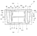
- FIG. 1 is a side view showing an outline of the reactor according to the first embodiment.
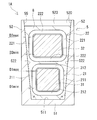
- FIG. 2 is a sectional view showing an outline of the reactor taken along the line (II)-(II) of FIG.
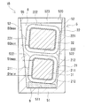
- FIG. 3 is a sectional view showing an outline of the reactor according to the second embodiment.
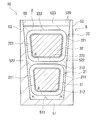
- FIG. 4 is a cross-sectional view showing the outline of the reactor according to the third embodiment.
- the space for installing the reactor may be so small that the pair of winding parts cannot be placed flat.
- stacking in the direction orthogonal to the installation surface may be referred to as vertical stacking.
- the distance between the side surface of the upper winding portion and the side wall portion of the case facing the side surface is smaller than that of the lower winding portion. It becomes larger than the distance between the side surface of the winding portion and the side wall portion of the case.
- the inner wall surface of the side wall portion of the case is usually formed with an inclined surface that is inclined from the inner bottom surface of the bottom plate portion of the case toward the opposite side so as to be away from each other at a distance facing each other.
- the case is typically manufactured by die casting such as die casting or injection molding.
- the inclined surface of the inner wall surface is formed by transferring a draft provided in the mold for releasing the case from the mold when the case is manufactured.
- the case for accommodating the pair of vertically stacked winding portions is deeper than the case for accommodating the pair of flatly arranged winding portions. The deeper the case, the larger the distance between the side surface of the upper winding part and the inner wall surface of the case.
- the gap between the side surface of the upper winding part and the inner wall surface of the case becomes large, so that the upper winding part is less likely to radiate through the inner wall surface of the case. That is, the lower winding portion is easily cooled, and the upper winding portion is difficult to cool. As a result, when the temperature of the upper winding portion becomes higher than that of the lower winding portion, the loss of the reactor increases.
- one of the purposes of the present disclosure is to provide a reactor with a small installation area and low loss.
- the reactor according to the present disclosure has a small installation area and low loss.
- a reactor according to an aspect of the present disclosure is A reactor comprising a combination of a coil and a magnetic core, a case that houses the combination, and a sealing resin portion that is filled inside the case and seals at least a part of the combination.
- the case is An inner bottom surface on which the combination is placed, A pair of coil facing surfaces facing the side surface of the coil, The pair of coil facing surfaces has an inclined surface that is inclined from the inner bottom surface side toward the opposite side of the inner bottom surface so as to be apart from each other,
- the coil is A first winding portion arranged on the inner bottom surface side, A second winding portion arranged on the side opposite to the inner bottom surface side of the first winding portion, The first winding portion and the second winding portion are vertically stacked so that their axes are parallel to each other, The width of the second winding portion is larger than the width of the first winding portion.
- the installation area is smaller than that in the case where the first winding part and the second winding part are placed flat. small.
- the length of the combination along the direction orthogonal to both the parallel direction of the first winding part and the second winding part and the axial direction of the coil is such that the first winding part and the second winding part are This is because it is smaller than the length of the combination along the parallel direction of the parts.
- the above reactor has low loss.
- the height of each of the first winding portion and the second winding portion is constant, by making the width of the second winding portion larger than the width of the first winding portion, Compared with the case where the second winding portion has the same width, the distance between the side surface of the second winding portion and the inclined surface facing the side surface is likely to be smaller. Therefore, the second winding portion is likely to radiate heat. Therefore, the first winding portion and the second winding portion are likely to be uniformly cooled via the coil facing surface of the case. The uniform cooling of the first winding portion and the second winding portion easily reduces the maximum temperature of the coil. Reducing the maximum coil temperature tends to reduce reactor loss.
- the definition of the width of the winding portion will be described later.
- the above reactor can reduce the cost.
- the reason is that it is possible to easily dissipate heat in the second winding portion simply by making the width of the second winding portion larger than the width of the first winding portion as described above. This is because it does not need to be made of high resin or the like.
- a resin having a high thermal conductivity easily radiates heat from the second winding portion even if the distance between the side surface of the second winding portion and the inclined surface is large to some extent, but the cost is relatively high.
- the inner bottom surface is a flat surface, Each end face shape of the first winding portion and the second winding portion, It has a rectangular frame shape, A pair of case facing sides that extend in the vertical direction and that face each of the inclined surfaces, A pair of connecting sides connecting one end side and the other end side of the pair of case facing sides, The pair of connecting sides may be parallel to the inner bottom surface.
- the distance between each side surface and each inclined surface of the first winding portion along the width direction gradually increases from the inner bottom surface side to the opposite side.
- the distance between each side surface and each inclined surface of the second winding portion along the width direction gradually increases from the inner bottom surface side to the opposite side.
- Each end face shape of the first winding portion and the second winding portion It has a rectangular frame shape, One case facing side that is parallel to and faces one of the inclined surfaces, It is possible to have the other case facing side that is non-parallel and that faces the other inclined surface.
- the above reactor has even lower loss.
- the distance between the one side surface of the first winding portion and the one inclined surface can be made uniform from the inner bottom surface side to the opposite side.
- the distance between the one side surface and the one inclined surface of the second winding portion can be made uniform from the inner bottom surface side to the opposite side.
- the reactor has a uniform spacing between one side surface of the first winding portion and one inclined surface and a spacing between one side surface of the second winding portion and one inclined surface.
- the second winding portion can easily dissipate heat from one side surface thereof.
- one side surface of the first winding portion and one side surface of the second winding portion are brought into surface contact with one inclined surface, if necessary. Therefore, in the reactor described above, the second winding portion can more easily dissipate heat from one side surface thereof.
- the interval along the width direction between the other side surface of the first winding portion and the other inclined surface gradually increases from the inner bottom surface side to the opposite side.
- the distance between the other side surface and the other inclined surface of the second winding portion along the width direction gradually increases from the inner bottom surface side to the opposite side.
- the distance along the width direction between each side surface and each inclined surface of the first winding portion and the distance along the width direction between the side surface and the inclined surface of the second winding portion are It is possible to make them uniform from the bottom side to the opposite side. Therefore, in the reactor described above, the second winding portion can easily dissipate heat from the other side surface. Therefore, the reactor described above can easily uniformly cool the first winding portion and the second winding portion via the coil facing surfaces of the case.
- Each end face shape of the first winding portion and the second winding portion It has a trapezoidal frame shape, It can be mentioned that the case has a pair of case facing sides that face each of the inclined surfaces and are parallel to each other.
- the above reactor has even lower loss.
- the distance between the one side surface of the first winding portion and the one inclined surface, and the distance between the other side surface of the first winding portion and the other inclined surface from the inner bottom surface side to the opposite side. Can be made uniform.
- interval between each side surface of each 2nd winding part and each inclined surface can be made uniform. Therefore, the first winding portion and the second winding portion are likely to be uniformly cooled via the coil facing surfaces of the case.
- the magnetic core has a first inner core portion and a second inner core portion arranged inside the first winding portion and the second winding portion,
- the cross-sectional shape of the first inner core portion and the second inner core portion taken along a cutting plane orthogonal to the magnetic flux in each inner core portion has an inner peripheral shape of the first winding portion and the second winding portion.
- the shape follows
- the width of the second inner core portion may be larger than the width of the first inner core portion.
- the cross-sectional shape of the first inner core is a shape along the inner peripheral shape of the first winding portion, the distance between the first winding portion and the first inner core portion is It tends to be uniform in the circumferential direction. Similarly, the spacing between the second winding portion and the second inner core portion is likely to be uniform in the circumferential direction of the second inner core portion.
- the width of the second inner core portion is larger than the width of the first inner core portion, and the width of the second winding portion is larger than the width of the first winding portion.
- the gap between the second winding portion and the second inner core portion is likely to be smaller than when the core portion has the same width. Further, the size of the space between the first winding part and the first inner core part and the size of the space between the second winding part and the second inner core part are likely to be the same. Furthermore, if the facing intervals of the inclined surfaces are the same, the width of the second inner core portion can be increased as compared with the case where the first winding portion and the second winding portion have the same width. Therefore, the reactor can increase the inductance.
- An angle formed by the inner bottom surface and each of the inclined surfaces is 91 ° or more and 95 ° or less.
- the case is typically manufactured by die casting such as die casting or injection molding.
- the inclined surface is formed by transferring a draft provided in the mold for releasing the case from the mold when the case is manufactured. If the angle is 91 ° or more, the first winding portion and the second winding portion have the same width, and when the first winding portion and the second winding portion are vertically stacked, the second winding on the upper stage side The distance between the side surface of the winding portion and the inclined surface tends to be larger than the distance between the side surface of the second winding portion on the lower stage side and the inclined surface.
- the width of the second winding portion is larger than the width of the first winding portion, it is possible to reduce the distance between the side surface and the inclined surface of the second winding portion on the upper stage side. Therefore, even if they are stacked vertically, the second winding portion is likely to radiate heat through the side wall portion of the case. If the angle is 95 ° or less, the angle is not too large. Therefore, the difference in width between the first winding portion and the second winding portion is not too large. Therefore, it is unlikely that a difference occurs in the heat generation characteristics of the second winding portion and the first winding portion.
- the reactor 1A includes a combined body 10 in which the coil 2 and the magnetic core 3 are combined, a case 5, and a sealing resin portion 8.
- the case 5 includes a bottom plate portion 51 on which the combined body 10 is placed, and a side wall portion 52 that surrounds the outer periphery of the combined body 10.
- the pair of coil facing surfaces 521 facing the side surface of the coil 2 in the side wall portion 52 have inclined surfaces 522 that are inclined from the bottom plate portion 51 side toward the opposite side of the bottom plate portion 51 so as to be separated from each other.
- the sealing resin portion 8 is filled inside the case 5 and seals at least a part of the combined body 10.
- the coil 2 has a first winding portion 21 and a second winding portion 22 formed by winding a winding.
- the first winding portion 21 is arranged on the bottom plate portion 51 side.
- the second winding portion 22 is arranged on the side opposite to the bottom plate portion 51 side of the first winding portion 21.
- the first winding portion 21 and the second winding portion 22 are vertically stacked so that their axes are parallel to each other.
- One of the features of the reactor 1A is that the width of the second winding portion 22 is larger than the width of the first winding portion 21. The following description will be made in the order of the main characteristic part of the reactor 1A, the structure of the part related to the characteristic part, the main effect, and each structure.
- the direction along the vertical direction is the depth direction of the case 5. 1 and 2, the upper side of the paper surface is the upper side and the lower side of the paper surface is the lower side.
- the direction along this vertical direction is called the height direction or the vertical direction.
- the direction orthogonal to both the height direction and the axial direction of the coil 2 is called the width direction.
- the left-right direction of the paper surface is the width direction.
- the case 5 houses the combination 10 inside.
- the case 5 can protect the combination 10 mechanically and from the external environment. The protection from the external environment improves the corrosion resistance of the combination 10. Moreover, the case 5 can dissipate heat from the combination 10.
- the case 5 is a bottomed cylindrical container.
- the case 5 includes a bottom plate portion 51 and a side wall portion 52. In FIG. 1, for convenience of explanation, the illustration of the side wall portion on the front side of the drawing is omitted.
- the bottom plate portion 51 and the side wall portion 52 are integrally formed in this example.
- the bottom plate portion 51 and the side wall portion 52 may be individually molded.
- the bottom plate portion 51 and the side wall portion 52 may be integrated with each other by screwing or the like.
- An opening 55 is formed on the upper end side of the side wall 52.
- the inner space surrounded by the bottom plate portion 51 and the side wall portion 52 has a shape and size capable of accommodating the entire combined body 10.
- the bottom plate portion 51 has an inner bottom surface 511 on which the combined body 10 is placed, and an outer bottom surface to be installed on an installation target such as a cooling base. Illustration of the installation target is omitted.
- the bottom plate portion 51 has a rectangular flat plate shape. The inner bottom surface 511 and the outer bottom surface are flat in this example.
- the side wall portion 52 surrounds the outer periphery of the combined body 10.
- the side wall portion 52 is provided upright on the peripheral edge of the bottom plate portion 51.
- the side wall 52 has a rectangular frame shape in this example.
- the height of the side wall portion 52 is higher than the height of the combined product 10.
- the inner wall surface 520 of the side wall portion 52 has four surfaces, a pair of coil facing surfaces 521 and a pair of core facing surfaces 523 (FIG. 1).
- the pair of coil facing surfaces 521 face each other.
- the pair of core facing surfaces 523 face each other.
- the facing direction of the pair of coil facing surfaces 521 and the facing direction of the pair of core facing surfaces 523 are orthogonal to each other.
- Each coil facing surface 521 faces the side surface of the coil 2. That is, each coil facing surface 521 faces the first winding portion 21 and the second winding portion 22.
- the side surfaces of the first winding part 21 and the second winding part 22 are the outer circumferences of the first winding part 21 and the second winding part 22 of the first winding part 21 and the second winding part 22, respectively.
- Each coil facing surface 521 has an inclined surface 522 that is inclined from the inner bottom surface 511 side of the case 5 toward the opening 55 side so as to be separated from each other.
- a groove portion into which the end surface member 41 is fitted may be formed at a position facing the end surface member 41 of the holding member 4 described later, in the depth direction of the case 5. Illustration of the groove is omitted. If the groove is formed, the combination 10 of the coil 2, the magnetic core 3 and the holding member 4 can be easily positioned with respect to the case 5.
- each core facing surface 523 faces the outer end surface of the outer core portion 33.
- the outer end surface of the outer core portion 33 is a surface of the outer core portion 33 opposite to the first inner core portion 31 and the second inner core portion 32.
- each core facing surface 523 has an inclined surface 524 that is inclined so as to be away from the inner bottom surface 511 side of the case 5 toward the opening 55 side.
- the case 5 is typically manufactured by die casting such as die casting or injection molding.
- the inclined surfaces 522 and 524 are formed by transferring the draft angle provided in the mold for releasing the case 5 from the mold when the case 5 is manufactured.
- the angle (angle ⁇ ) formed by each of the inclined surface 522 and the inclined surface 524 and the inner bottom surface 511 is preferably 91 ° or more and 95 ° or less (FIGS. 1 and 2). 1 and 2, the inclination angles of the inclined surface 522 and the inclined surface 524 are exaggerated for convenience of description.
- the angles formed by the inclined surface 522 and the inclined surface 524 and the inner bottom surface 511 are all the same in this example.
- the angle formed by the inclined surface 522 and the inner bottom surface 511 and the angle formed by the inclined surface 524 and the inner bottom surface 511 may be different from each other.
- the mold releasability of Case 5 is high. If the angle ⁇ is 91 ° or more, the widths of the first winding portion 21 and the second winding portion 22 are the same, and the axes of the first winding portion 21 and the second winding portion 22 are parallel to each other.
- the space between the side surface of the second winding portion 22 on the upper stage side and the inclined surface 522 is the same as the side surface of the second winding portion 22 on the lower stage side. It tends to be larger than the distance between the inclined surface 522 and the inclined surface 522.
- the direction orthogonal to the inner bottom surface 511 is the depth direction of the case 5.
- stacking in the depth direction of the case 5 may be referred to as vertical stacking.
- the width of the second winding portion 22 larger than the width of the first winding portion 21, the gap between the side surface of the second winding portion 22 on the upper stage side and the inclined surface 522. Can be made smaller. Therefore, the second winding portion 22 is likely to radiate heat via the side wall portion 52 of the case 5 even if the above-mentioned products are stacked vertically.
- the angle ⁇ is 95 ° or less, the angle is not too large. Therefore, the difference between the width of the first winding portion 21 and the width of the second winding portion 22 is not too large. Therefore, the difference in heat generation characteristics between the second winding portion 22 and the first winding portion 21 is unlikely to occur.
- Examples of the material of the case 5 include a non-magnetic metal and a non-metal material.
- the non-magnetic metal include aluminum and its alloys, magnesium and its alloys, copper and its alloys, silver and its alloys, and austenitic stainless steel. The thermal conductivity of these non-magnetic metals is relatively high. Therefore, the case 5 can be used as a heat dissipation path, and the heat generated in the combination 10 can be efficiently dissipated to an installation target such as a cooling base. Therefore, the reactor 1A can improve heat dissipation.
- die casting can be preferably used as a method of forming the case 5.
- non-metal material examples include resins such as polybutylene terephthalate (PBT) resin, urethane resin, polyphenylene sulfide (PPS) resin, and acrylonitrile-butadiene-styrene (ABS) resin.
- PBT polybutylene terephthalate
- PPS polyphenylene sulfide
- ABS acrylonitrile-butadiene-styrene
- the resin may contain a ceramics filler. Examples of the ceramic filler include alumina and silica. Resins containing these ceramic fillers are excellent in heat dissipation and electrical insulation.
- injection molding can be preferably used as a method of forming the case 5.
- the bottom plate portion 51 and the side wall portion 52 are individually molded, the bottom plate portion 51 and the side wall portion 52 may be made of different materials.
- the first winding portion 21 and the second winding portion 22 included in the coil 2 are hollow cylindrical bodies formed by spirally winding separate windings.
- the first winding portion 21 and the second winding portion 22 are rectangular tubular bodies.
- the first winding portion 21 and the second winding portion 22 can also be formed by a single winding.
- the first winding portion 21 and the second winding portion 22 are electrically connected to each other. The method of electrical connection will be described later.
- a covered wire having an insulating coating on the outer circumference of the conductor wire can be used.
- the material of the conductor wire include copper, aluminum, magnesium, and alloys thereof.
- Examples of the conductor wire include a rectangular wire and a round wire.
- Examples of the insulating coating include enamel.
- a typical example of the enamel is polyamide-imide.
- a coated rectangular wire whose conductor wire is a copper rectangular wire and whose insulating coating is enamel is used.
- the first winding part 21 and the second winding part 22 are constituted by an edgewise coil obtained by edgewise winding the coated rectangular wire.
- the cross-sectional areas of the windings of the first winding portion 21 and the second winding portion 22 are the same in this example.
- the first winding part 21 and the second winding part 22 are wound in the same direction.
- the first winding part 21 and the second winding part 22 have the same number of turns.
- the cross-sectional area and the number of turns of the windings of the first winding portion 21 and the second winding portion 22 may be different from each other.
- the first winding part 21 and the second winding part 22 are arranged vertically in the depth direction of the case 5 so that their axes are parallel to each other. This parallel does not include the same straight line.
- the first winding portion 21 is arranged on the bottom plate portion 51 side.
- the second winding portion 22 is arranged above the first winding portion 21, that is, on the side opposite to the bottom plate portion 51 side.
- the end face shapes of the first winding part 21 and the second winding part 22 are rectangular frame shapes (FIG. 2).
- the rectangular frame shape here includes a square frame shape.
- the corners of the first winding portion 21 and the second winding portion 22 are rounded.
- the end surface shapes of the first winding portion 21 and the second winding portion 22 may be trapezoidal frame shapes or the like. Examples of the trapezoidal frame shape include an isosceles trapezoidal frame shape (FIG. 4) and a right-angled trapezoidal frame shape described later. Illustration of a right-angled trapezoidal frame is omitted.
- the end face shape of the first winding portion 21 has a pair of case facing sides 211 and a pair of connecting sides 212 (FIG. 2).
- the pair of case facing sides 211 face the inclined surfaces 522 of the coil facing surfaces 521 of the side wall portion 52.
- the pair of connecting sides 212 connects one end side and the other end side of the pair of case facing sides 211.
- the pair of case facing sides 211 are parallel to the depth direction of the case 5.
- Each connecting side 212 is parallel to the inner bottom surface 511 of the bottom plate portion 51.
- Each connecting side 212 extends along the width direction of the case 5.
- the end face shape of the second winding portion 22 has a pair of case facing sides 221 and a pair of connecting sides 222 (FIG. 2).
- the pair of case facing sides 221 face the inclined surfaces 522 of the coil facing surfaces 521 of the side wall portion 52.
- the pair of connecting sides 222 connects one end side and the other end side of the pair of case facing sides 221.
- the pair of case facing sides 221 are parallel to the depth direction of the case 5.
- Each connecting side 222 is parallel to the inner bottom surface 511 of the bottom plate portion 51.
- Each connection side 222 extends along the width direction of the case 5.
- the heights of the first winding portion 21 and the second winding portion 22 are the same in this example. That is, the length of the pair of case facing sides 211 of the first winding portion 21 and the length of the pair of case facing sides 221 of the second winding portion 22 are the same. The heights of the first winding portion 21 and the second winding portion 22 may be different from each other.
- the width of the second winding part 22 is larger than the width of the first winding part 21. That is, the length of the pair of connecting sides 222 in the second winding portion 22 is longer than the length of the pair of connecting sides 212 in the first winding portion 21.
- FIG. 2 exaggerates the magnitude relationship between the widths of the first winding portion 21 and the second winding portion 22.
- the width of the second winding portion 22 is preferably a length that satisfies both the following condition (1) and condition (2).
- the minimum distance D2min along the width direction between each side surface of the second winding portion 22 and each inclined surface 522 is between each side surface of the first winding portion 21 and each inclined surface 522. It is not more than the minimum distance D1min along the width direction.
- the maximum distance D2max along the width direction between each side surface of the second winding portion 22 and each inclined surface 522 is between each side surface of the first winding portion 21 and each inclined surface 522. It is less than or equal to the maximum distance D1max along the width direction.
- the width of the second winding portion 22 is a length that satisfies both the condition (1) and the condition (2), the second winding portion 22 is likely to radiate heat via the side wall portion 52 of the case 5. Therefore, the first winding portion 21 and the second winding portion 22 are likely to be uniformly cooled via the side wall portion 52 of the case 5. Even cooling of the first winding portion 21 and the second winding portion 22 facilitates reduction of the maximum temperature of the coil 2. By reducing the maximum temperature of the coil 2, the loss of the reactor 1A is easily reduced.
- the width of the second winding portion 22 is such that the minimum distance D2min is smaller than the minimum distance D1min and the maximum distance D2max is smaller than the maximum distance D1max. Is preferred.
- the second winding portion 22 is more likely to generate heat with higher resistance than the first winding portion 21. Since the width of the second winding portion 22 is larger than the width of the first winding portion 21, the total length of the conductor of the second winding portion 22 is longer than the total length of the conductor of the first winding portion 21. is there. Therefore, if the minimum distance D2min ⁇ the minimum distance D1min and the maximum distance D2max ⁇ the maximum distance D1max are satisfied, the second winding portion 22, which is more likely to generate heat, is likely to be effectively radiated. Therefore, the second winding portion 22 and the first winding portion 21 are likely to be cooled uniformly.
- the distance between each side surface of the first winding portion 21 and each inclined surface 522 along the width direction gradually increases from the inner bottom surface 511 side to the opening 55 side.
- the distance between each side surface of the second winding portion 22 and each inclined surface 522 along the width direction gradually increases from the inner bottom surface 511 side to the opening 55 side.
- the minimum distance D1min is the distance between the inner bottom surface 511 side and each inclined surface 522 on each side surface of the first winding portion 21 along the width direction.
- the maximum gap D1max is a gap along the width direction between the opening 55 side and each inclined surface 522 on each side surface of the first winding portion 21.
- the minimum distance D2min is a distance along the width direction between the inner bottom surface 511 side and each inclined surface 522 on each side surface of the second winding portion 22.
- the maximum distance D2max is a distance along the width direction between the opening 55 side and each inclined surface 522 on each side surface of the second winding portion 22.
- the minimum distance D1min and the minimum distance D2min are substantially the same.
- the maximum distance D1max and the maximum distance D2max are substantially the same. Therefore, the second winding portion 22 and the first winding portion 21 are likely to be uniformly cooled via the side wall portion 52 of the case 5.
- the magnetic core 3 includes a first inner core portion 31, a second inner core portion 32, and a pair of outer core portions 33 (FIG. 1).
- the first inner core portion 31 and the second inner core portion 32 are arranged inside the first winding portion 21 and the second winding portion 22, respectively.
- the first inner core portion 31 and the second inner core portion 32 mean portions of the magnetic core 3 along the axial direction of the first winding portion 21 and the second winding portion 22.
- both ends of the magnetic core 3 along the axial direction of the first winding part 21 and the second winding part 22 are located outside the first winding part 21 and the second winding part 22.
- the protruding portion is also a part of the first inner core portion 31 and the second inner core portion 32.
- the pair of outer core portions 33 are arranged outside the first winding portion 21 and the second winding portion 22. That is, in the outer core portion 33, the coil 2 is not arranged, but the outer core portion 33 is projected from the coil 2 and is exposed from the coil 2.
- the magnetic core 3 is formed in an annular shape by contacting the end surfaces of the first inner core portion 31 and the second inner core portion 32 with the inner end surface of the outer core portion 33. That is, the pair of outer core portions 33 are arranged so as to sandwich the first inner core portion 31 and the second inner core portion 32 which are arranged separately. The first inner core portion 31, the second inner core portion 32, and the pair of outer core portions 33 form a closed magnetic circuit when the coil 2 is excited.
- the shapes of the first inner core portion 31 and the second inner core portion 32 are preferably shapes along the inner peripheral shapes of the first winding portion 21 and the second winding portion 22. This is because the distance between the inner peripheral surface of the first winding portion 21 and the outer peripheral surface of the first inner core portion 31 tends to be uniform in the circumferential direction of the first inner core portion 31. In addition, the distance between the inner peripheral surface of the second winding portion 22 and the outer peripheral surface of the second inner core portion 32 is likely to be uniform in the circumferential direction of the second inner core portion 32. In this example, the shapes of the first inner core portion 31 and the second inner core portion 32 are rectangular parallelepiped. The corner portions of the first inner core portion 31 and the second inner core portion 32 are rounded along the inner peripheral surfaces of the corner portions of the first winding portion 21 and the second winding portion 22.
- the height of the first inner core portion 31 and the height of the second inner core portion 32 are the same in this example.
- the width of the second inner core portion 32 is preferably larger than the width of the first inner core portion 31. If the width of the second inner core portion 32 is larger than the width of the first inner core portion 31, the width of the second winding portion 22 is larger than the width of the first winding portion 21. This is because the gap between the inner peripheral surface of the second winding portion 22 and the outer peripheral surface of the second inner core portion 32 is likely to be smaller than in the case where the first inner core portion 31 and the first inner core portion 31 have the same width. .
- the size of the gap between the inner peripheral surface of the first winding portion 21 and the outer peripheral surface of the first inner core portion 31, and the inner peripheral surface of the second winding portion 22 and the outer periphery of the second inner core portion 32 is likely to be the same as each other. Further, if the facing intervals of the inclined surfaces 522 are the same, the width of the second inner core portion 32 should be made larger than that in the case where the first winding portion 21 and the second winding portion 22 have the same width. You can Therefore, the inductance can be increased.
- the width of the first inner core portion 31 and the width of the second inner core portion 32 in this example is the size of the interval between the inner peripheral surface of the first winding portion 21 and the outer peripheral surface of the first inner core portion 31. And the size of the interval between the inner peripheral surface of the second winding portion 22 and the outer peripheral surface of the second inner core portion 32 are the same.
- the first inner core portion 31 and the second inner core portion 32 of this example are composed of one columnar core piece.
- the core pieces do not go through the gap.
- the core piece has a length of substantially the entire axial length of the first winding portion 21 and the second winding portion 22.
- the first inner core portion 31 and the second inner core portion 32 may be configured by a laminated body in which a plurality of columnar core pieces and gaps are laminated and arranged along the axial direction of the coil 2.
- Examples of the shape of the outer core portion 33 include a rectangular parallelepiped shape and a quadrangular pyramid shape.
- the rectangular parallelepiped shape is a columnar body in which the outer end surface, the side surface, the upper surface, and the lower surface of the outer core portion 33 are all rectangular. The areas of the upper surface and the lower surface are the same.
- the quadrangular pyramid shape is, for example, a columnar body in which the outer end surface, the upper surface, and the lower surface of the outer core portion 33 are rectangular, and the side surfaces are rectangular trapezoidal.
- a columnar body in which the outer end surface of the outer core portion 33 has an isosceles trapezoidal shape and the side surfaces, the upper surface, and the lower surface have rectangular shapes can be used.
- the outer end surface of the outer core portion 33 may have an isosceles trapezoidal shape, the side surfaces thereof may have a right-angled trapezoidal shape, and the upper and lower surfaces may have a rectangular columnar shape.
- the columnar body in which the outer end surface of the outer core portion 33 has an isosceles trapezoidal shape can be suitably used when the width of the second inner core portion 32 is wider than the width of the first inner core portion 31.
- the area of the upper surface of the quadrangular pyramid-shaped outer core portion 33 is larger than the area of the lower surface.
- the outer core portion 33 in this example has a truncated pyramid shape.
- the outer core portion 33 may be a columnar body in which the outer end surface, the upper surface, and the lower surface have a rectangular shape, and the side surfaces have a right-angled trapezoidal shape (FIG. 1).
- the outer end surface of the outer core portion 33 is preferably configured as a surface parallel to the inclined surface 524 of the core facing surface 523. The reason is that the outer end surface of the outer core portion 33 and the inclined surface 524 of the core facing surface 523 can be brought into surface contact with each other. Due to this surface contact, the heat of the outer core portion 33 is easily transferred to the side wall portion 52 of the case 5. Therefore, the heat dissipation of the magnetic core 3 tends to be high. Moreover, the pair of outer core portions 33 can be pressed in the directions in which they approach each other. Therefore, the magnetic core 3 is less likely to be displaced with respect to the case 5.
- the upper surface of the outer core portion 33 is substantially flush with the upper surface of the second inner core portion 32 in this example.
- the lower surface of the outer core portion 33 is substantially flush with the lower surface of the first inner core portion 31 in this example.
- the upper surface of the outer core portion 33 may be higher than the upper surface of the second inner core portion 32.
- the lower surface of the outer core portion 33 may be below the lower surface of the first inner core portion 31.
- the sealing resin part 8 is filled in the case 5 and covers at least a part of the combined body 10.
- the sealing resin portion 8 transfers the heat of the combined body 10 to the case 5, mechanically protects the combined body 10 and protects it from the external environment, improves the corrosion resistance of the combined body 10, and between the combined body 10 and the case 5.
- Various functions such as improvement of the electric insulation property, integration of the combined body 10 and improvement of strength and rigidity of the reactor 1A by integrating the combined body 10 and the case 5.
- the encapsulating resin portion 8 of the present example embeds substantially the entire assembly 10.
- the sealing resin portion 8 has a portion interposed between the coil 2 and the case 5.
- the encapsulation resin portion 8 is provided between the lower surface of the first winding portion 21 and the inner bottom surface 511 of the bottom plate portion 51, the side surface of the first winding portion 21 and the coil facing surface 521 of the side wall portion 52. In between, it is interposed between the side surface of the second winding portion 22 and the coil facing surface 521.
- the sealing resin portion 8 is also interposed between the upper surface of the first winding portion 21 and the lower surface of the second winding portion 22. The heat of the first winding portion 21 and the second winding portion 22 is easily transferred to the case 5 via the sealing resin portion 8.
- thermosetting resin and the thermoplastic resin may be used as the material of the sealing resin portion 8.
- thermosetting resin include epoxy resin, urethane resin, silicone resin, unsaturated polyester resin and the like.
- thermoplastic resin include PPS resin and the like. These resins may contain the above-mentioned ceramic filler and the like.
- the reactor 1A according to the first embodiment can achieve the following effects.
- the length of the combined body 10 along the direction orthogonal to both the parallel direction of the first winding portion 21 and the second winding portion 22 and the axial direction of the coil 2 is determined by the length of the first winding portion 21 and the second winding portion. This is because it is smaller than the length of the combined product 10 along the parallel direction of the turning portions 22.
- the width of the second winding portion 22 is made larger than the width of the first winding portion 21.
- the distance between the side surface of the second winding portion 22 and the inclined surface 522 facing the side surface is likely to be small. Therefore, the second winding portion 22 is likely to dissipate heat.
- the minimum distance D2min is substantially the same as the minimum distance D1min
- the maximum distance D2max is substantially the same as the maximum distance D1max.
- first winding portion 21 and the second winding portion 22 are likely to be uniformly cooled via the side wall portion 52 of the case 5. Even cooling of the first winding portion 21 and the second winding portion 22 facilitates reduction of the maximum temperature of the coil 2. Therefore, reduction of the maximum temperature of the coil 2 tends to reduce loss of the reactor 1A.
- the conductors at the ends on the one end side of the coil 2 in the axial direction are directly connected to each other.
- the conductors are connected by bending the ends of the winding of the first winding part 21 and extending to the ends of the winding of the second winding part 22.
- the conductors may be connected to each other via a connecting member that is independent of the first winding portion 21 and the second winding portion 22.
- the connecting member is made of, for example, the same member as the winding.
- the conductors can be connected by welding or pressure welding.
- both ends of each winding on the other end side in the axial direction of the coil 2 are extended upward from the opening 55 of the case 5, although not shown.
- the insulating coating is peeled off to expose the conductor.
- a terminal member is connected to the exposed conductor.
- the coil 2 is connected to an external device such as a power source for supplying electric power to the coil 2 via the terminal member. Illustration of the terminal member and the external device is omitted.
- the first winding part 21 and the second winding part 22 may be individually integrated by an integrated resin. Illustration of the integrated resin is omitted.
- the integrated resin covers the outer peripheral surface, the inner peripheral surface, and the end surface of the first winding portion 21 and the second winding portion 22, and joins adjacent turns.
- a resin having a coating layer of heat-sealing resin formed on the outer circumference of the winding is used, and the winding can be wound and then heated to melt the coating layer.
- the outer circumference of the winding refers to a further outer circumference of the insulating coating of the winding.
- the heat fusion resin include thermosetting resins such as epoxy resin, silicone resin and unsaturated polyester.
- the first inner core portion 31, the second inner core portion 32, and the outer core portion 33 are made of a powder compact or a composite material.
- the powder compact is formed by compression molding soft magnetic powder.
- the powder compact can have a higher proportion of the soft magnetic powder in the core piece as compared with the composite material. Therefore, the green compact is easy to enhance the magnetic properties.
- the magnetic characteristics include relative permeability and saturation magnetic flux density.
- the composite material is formed by dispersing soft magnetic powder in resin.
- the composite material can be obtained by filling a mold with a fluid material in which soft magnetic powder is dispersed in an unsolidified resin and curing the resin.
- the composite material can easily adjust the content of the soft magnetic powder in the resin. Therefore, the composite material is easy to adjust the magnetic characteristics.
- the composite material is easier to form even in a complicated shape as compared with the powder compact.
- the first inner core portion 31, the second inner core portion 32, and the outer core portion 33 may be a hybrid core in which the outer periphery of the powder compact is covered with the composite material.
- the first inner core portion 31 and the second inner core portion 32 are made of a composite material.
- the pair of outer core portions 33 are formed of a powder compact.
- the soft magnetic powder particles include soft magnetic metal particles, coated particles having an insulating coating around the soft magnetic metal particles, and soft magnetic non-metal particles.
- soft magnetic metals include pure iron and iron-based alloys.
- iron-based alloys include Fe-Si alloys and Fe-Ni alloys.
- the insulating coating include phosphate.
- soft magnetic non-metals include ferrite.
- a thermosetting resin or a thermoplastic resin can be used as the resin of the composite material.
- the thermosetting resin include epoxy resin, phenol resin, silicone resin and urethane resin.
- the thermoplastic resin include PPS resin, polyamide (PA) resin, liquid crystal polymer (LCP), polyimide resin, and fluororesin.
- PA resin examples include nylon 6, nylon 66, nylon 9T and the like. These resins may contain the above-mentioned ceramics filler.
- the gap is made of a material having a smaller relative magnetic permeability than the first inner core portion 31, the second inner core portion 32, and the outer core portion 33.
- the relative magnetic permeability of the first inner core portion 31 and the second inner core portion 32 is preferably 5 or more and 50 or less, more preferably 10 or more and 30 or less, and particularly preferably 20 or more and 30 or less.
- the relative magnetic permeability of the outer core portion 33 preferably satisfies at least twice the relative magnetic permeability of the first inner core portion 31 and the second inner core portion 32.
- the relative magnetic permeability of the outer core portion 33 is preferably 50 or more and 500 or less.
- the combined body 10 may include the holding member 4 (FIG. 1).
- the holding member 4 ensures insulation between the coil 2 and the magnetic core 3.
- the holding member 4 of this example has a pair of end surface members 41.
- the end surface member 41 ensures insulation between each end surface of the coil 2 and each outer core portion 33.
- the shape of each end surface member 41 is the same.
- Each end surface member 41 is a frame-shaped plate member in which two through holes 410 are provided along the stacking direction of the first winding portion 21 and the second winding portion 22.
- the first inner core portion 31 and the second inner core portion 32 are fitted into the respective through holes 410.
- the width of the through hole 410 into which the second inner core portion 32 is fitted is larger than the width of the through hole 410 into which the first inner core portion 31 is fitted.
- Two recesses 411 for accommodating the end faces of the first winding portion 21 and the second winding portion 22 are formed on the coil 2 side surface of each end surface member 41.
- Each of the recesses 411 on the coil 2 side makes the entire end surfaces of the first winding portion 21 and the second winding portion 22 come into surface contact with the end surface member 41.
- Each recess 411 is formed in a rectangular ring shape so as to surround the through hole 410.
- the holding member 4 may further include an inner member.
- the inner member ensures insulation between the inner peripheral surfaces of the first winding portion 21 and the second winding portion 22 and the outer peripheral surfaces of the first inner core portion 31 and the second inner core portion 32.
- Examples of the material of the holding member 4 include insulating materials such as various resins.
- the resin for example, the same resin as the resin of the composite material described above can be used.
- the other thermoplastic resin include polytetrafluoroethylene (PTFE) resin, PBT resin, ABS resin and the like.
- PTFE polytetrafluoroethylene
- other thermosetting resins include unsaturated polyester resins.
- the material of the holding member 4 is preferably the same as that of the sealing resin portion 8. This is because the holding member 4 and the sealing resin portion 8 can have the same linear expansion coefficient, and damage to each member due to thermal expansion and contraction can be suppressed.
- the combination 10 may include a mold resin portion.
- the mold resin portion covers each outer core portion 33 and extends inside the first winding portion 21 and the second winding portion 22.
- the mold resin portion covers a region of the outer peripheral surface of each outer core portion 33, excluding a connecting surface between the first inner core portion 31 and the second inner core portion 32.
- the mold resin portion is formed between each outer core portion 33 and the recess 412 of each end surface member 41, the outer peripheral surfaces of the first inner core portion 31 and the second inner core portion 32, and the through hole 410 of each end surface member 41. And the inner peripheral surfaces of the first winding portion 21 and the second winding portion 22 and the outer peripheral surfaces of the first inner core portion 31 and the second inner core portion 32.
- This mold resin portion can integrate each outer core portion 33, each end surface member 41, first inner core portion 31, second inner core portion 32, first winding portion 21, and second winding portion 22.
- the material of the mold resin portion for example, the same thermosetting resin or thermoplastic resin as the resin of the composite material described above can be used.
- These resins may contain the above-mentioned ceramics filler. The inclusion of the ceramics filler can improve the heat dissipation of the mold resin portion.
- the reactor 1A can be used as a component of a circuit that performs a voltage boosting operation or a voltage dropping operation.
- the reactor 1A can be used as, for example, various converters, components of a power conversion device, or the like.
- the converter include a vehicle-mounted converter mounted in a vehicle such as a hybrid vehicle, a plug-in hybrid vehicle, an electric vehicle, a fuel cell vehicle, and a converter for an air conditioner.
- a DC-DC converter is typically used as the in-vehicle converter.
- FIG. 3 is a sectional view showing a state in which the reactor 1B is cut at the same position as the sectional view shown in FIG.
- One case facing side 211 of the first winding portion 21 is parallel to the one inclined surface 522.
- the other case facing side 211 of the first winding portion 21 is not parallel to the other inclined surface 522.
- the pair of connecting sides 212 of the first winding portion 21 is not parallel to the inner bottom surface 511.
- the pair of connecting sides 212 is orthogonal to the one inclined surface 522 and intersects the other inclined surface 522 in a non-orthogonal manner.
- one case facing side 221 of the second winding portion 22 is parallel to the one inclined surface 522.
- the other case facing side 221 of the second winding portion 22 is not parallel to the other inclined surface 522.
- the pair of connecting sides 222 of the second winding portion 22 is not parallel to the inner bottom surface 511.
- the pair of connecting sides 222 is orthogonal to the one inclined surface 522 and intersects the other inclined surface 522 in a non-orthogonal manner.
- the length of the pair of case facing sides 211 of the first winding portion 21 and the length of the pair of case facing sides 221 of the second winding portion 22 are the same.
- the length of the pair of connecting sides 222 in the second winding portion 22 is longer than the length of the pair of connecting sides 212 in the first winding portion 21.
- the distance between the one side surface of the first winding portion 21 and the one inclined surface 522 can be made uniform from the inner bottom surface 511 side to the opening 55 side (the right side of the paper surface of FIG. 3). Similarly, the distance between the one side surface of the second winding portion 22 and the one inclined surface 522 can be made uniform from the inner bottom surface 511 side to the opening 55 side. Then, the distance between the one side surface of the first winding portion 21 and the one inclined surface 522 and the distance between the one side surface of the second winding portion 22 and the one inclined surface 522 are mutually uniform. Can be Therefore, the first winding portion 21 and the second winding portion 22 are likely to be uniformly cooled via the side wall portion 52 of the case 5.
- one side surface of the first winding portion 21 and one side surface of the second winding portion 22 are in surface contact with the one inclined surface 522 (on the right side of FIG. 3). Therefore, the first winding part 21 and the second winding part 22 are more easily cooled.
- a space is provided between one side surface of the first winding portion 21 and the second winding portion 22 and the one inclined surface 522.
- One side surface of the two-winding portion 22 and one inclined surface 522 are in direct contact with each other.
- the other side surface of the first winding portion 21 and the other side surface of the second winding portion 22 are not in contact with the other inclined surface 522 (the left side of the paper surface of FIG. 3).
- a predetermined space is provided between the other side surface of the first winding portion 21 and the other inclined surface 522 and between the other side surface of the second winding portion 22 and the other inclined surface 522. ing.
- the distance between the other side surface of the first winding portion 21 and the other inclined surface 522 gradually increases from the inner bottom surface 511 side to the opening 55 side.
- the distance between the other side surface of the second winding portion 22 and the other inclined surface 522 gradually increases from the inner bottom surface 511 side to the opening 55 side.
- the minimum distance D1min is a distance along the width direction between the inner bottom surface 511 side and the other inclined surface 522 on the other side surface of the first winding portion 21.
- the maximum gap D1max is a gap along the width direction between the opening 55 side and the other inclined surface 522 on the other side surface of the first winding portion 21.
- the minimum distance D2min is a distance along the width direction between the inner bottom surface 511 side and the other inclined surface 522 on the other side surface of the second winding portion 22.
- the maximum distance D2max is a distance along the width direction between the opening 55 side and the other inclined surface 522 on the other side surface of the second winding portion 22.
- the minimum distance D1min and the minimum distance D2min are substantially the same.
- the maximum distance D1max and the maximum distance D2max are substantially the same. Therefore, the second winding portion 22 is likely to dissipate heat. Therefore, the first winding portion 21 and the second winding portion 22 are likely to be uniformly cooled via the side wall portion 52 of the case 5.
- the reactor 1B preferably includes a pedestal portion 9.
- the pedestal portion 9 is arranged on the inner bottom surface 511 of the bottom plate portion 51.
- the pedestal portion 9 mounts the first winding portion 21 and the second winding portion 22 in an inclined state with respect to the inner bottom surface 511 of the bottom plate portion 51.
- the pedestal part 9 makes one case facing side 211 of the first winding part 21 and one case facing side 221 of the second winding part 22 parallel to the one inclined surface 522. That is, the upper surface of the pedestal portion 9 of this example is a surface along the direction orthogonal to the one inclined surface 522.
- the pedestal portion 9 of this example is composed of a member different from the case 5.
- the pedestal portion 9 is composed of a sheet-shaped member that supports substantially the entire lower surface of the first winding portion 21.
- the sectional shape of the pedestal portion 9 is a right-angled trapezoid.
- the upper surface of the pedestal portion 9 is formed as an inclined surface.
- the height of the pedestal portion 9 gradually increases from one inclined surface 522 side toward the other inclined surface 522 side.
- the pedestal portion 9 may be configured by a ridge member that supports one end side in the width direction on the lower surface of the first winding portion 21 in the axial direction of the first winding portion 21.
- the pedestal portion 9 can be configured by a part of the case 5.
- the inner bottom surface 511 may be formed of the inclined surface.
- the same non-magnetic metal or non-metallic material as that of the case 5 can be mentioned. If the pedestal portion 9 is made of these materials, the heat of the first winding portion 21 is easily transferred to the bottom plate portion 51 of the case 5 via the pedestal portion 9. Therefore, the first winding portion 21 is easily cooled.
- the pedestal portion 9 may be made of a non-magnetic metal sheet coated with a non-metal material. Then, the insulation between the first winding portion 21 and the case 5 tends to be high.
- the reactor 1B according to the second embodiment has low loss.
- the first winding part 21 and the second winding part 22 are arranged so as to be inclined so that one side surface of the first winding part 21 and the second winding part 22 and one inclined surface 522 are in surface contact with each other. This is because the second winding portion 22 is more easily cooled from the one side surface thereof.
- the minimum distance D2min is substantially the same as the minimum distance D1min
- the maximum distance D2max is substantially the same as the maximum distance D1max. Therefore, the second winding portion 22 is easily radiated from the other side surface. Therefore, the first winding portion 21 and the second winding portion 22 are likely to be uniformly cooled via the side wall portion 52 of the case 5, so that the maximum temperature of the coil 2 is easily reduced.
- FIG. 4 is a sectional view showing a state in which the reactor 1C is cut at the same position as the sectional view shown in FIG.
- the end face shapes of the first winding portion 21 and the second winding portion 22 are trapezoidal frame shapes which are equal to each other.
- the corners of the first winding portion 21 and the second winding portion 22 are rounded.
- the end face shape of the first winding portion 21 has a pair of case facing sides 211 and a pair of connecting sides 212.
- One case facing side 211 is parallel to the one inclined surface 522.
- the other case facing side 211 is parallel to the other inclined surface 522.
- Each connecting side 212 is parallel to the inner bottom surface 511 of the bottom plate portion 51.
- Each connecting side 212 extends along the width direction of the case 5. That is, the angle (angle ⁇ ) formed between each case facing side 211 and the lower connecting side 212 is the same as the angle (angle ⁇ ) formed between the inner bottom surface 511 and the inclined surface 522.
- the end face shape of the second winding portion 22 has a pair of case facing sides 221 and a pair of connecting sides 222.
- One case facing side 221 is parallel to the one inclined surface 522.
- the other case facing side 221 is parallel to the other inclined surface 522.
- Each connecting side 222 is parallel to the inner bottom surface 511 of the bottom plate portion 51.
- Each connecting side 212 extends along the width direction of the case 5. That is, the angle (angle ⁇ ) formed between each case facing side 221 and the lower connecting side 222 is the same as the angle (angle ⁇ ) formed between the inner bottom surface 511 and the inclined surface 522.
- the heights of the first winding portion 21 and the second winding portion 22 are the same in this example.
- the length of the pair of case facing sides 211 of the first winding portion 21 and the length of the pair of case facing sides 221 of the second winding portion 22 are the same.
- the width of the second winding part 22 is larger than the width of the first winding part 21.
- the width being large means that the width of the second winding portion 22 on the inner bottom surface 511 side is larger than the width of the first winding portion 21 on the opening 55 side. That is, the length of the lower connecting side 222 of the second winding portion 22 is longer than the length of the upper connecting side 212 of the first winding portion 21.
- the distance between the one side surface of the first winding portion 21 and the one inclined surface 522 is uniform from the inner bottom surface 511 side to the opening 55 side.
- the distance between the other side surface of the first winding portion 21 and the other inclined surface 522 is uniform from the inner bottom surface 511 side to the opening 55 side.
- the distance between the one side surface of the first winding portion 21 and the one inclined surface 522 and the distance between the other side surface of the first winding portion 21 and the other inclined surface 522 are substantially equal to each other. It is the same.
- the distance between the one side surface of the second winding portion 22 and the one inclined surface 522 is uniform from the inner bottom surface 511 side to the opening 55 side.
- the interval between the other side surface of the second winding portion 22 and the other inclined surface 522 is uniform from the inner bottom surface 511 side to the opening 55 side.
- the distance between the one side surface of the second winding portion 22 and the one inclined surface 522 and the distance between the other side surface of the second winding portion 22 and the other inclined surface 522 are substantially equal to each other. It is the same.
- each side surface of the first winding portion 21 and each inclined surface 522 and the distance between each side surface of the second winding portion 22 and each inclined surface 522 are substantially the same.
- the shape of the first inner core portion 31 and the second inner core portion 32 is an isosceles trapezoidal columnar body along the inner peripheral shape of the first winding portion 21 and the second winding portion 22, respectively.
- the interval between the first winding portion 21 and the first inner core portion 31 is uniform in the circumferential direction of the first inner core portion 31.
- the distance between the second winding portion 22 and the second inner core portion 32 is uniform in the circumferential direction of the second inner core portion 32.
- the height of the first inner core portion 31 and the height of the second inner core portion 32 are the same.
- the width of the second inner core portion 32 is larger than the width of the first inner core portion 31.
- the width of the second inner core portion 32 being larger means that the width of the second inner core portion 32 on the inner bottom surface 511 side is larger than the width of the first inner core portion 31 on the opening 55 side.
- the width of the first inner core portion 31 and the width of the second inner core portion 32 in this example are the size of the gap between the first winding portion 21 and the first inner core portion 31, and the second winding portion.
- the size of the gap between the second inner core portion 32 and the second inner core part 32 is substantially the same.
- the reactor 1C according to the third embodiment has a much lower loss than the reactor 1A according to the first embodiment.
- the distance between each side surface of the first winding portion 21 and each inclined surface 522 and the distance between each side surface of the second winding portion 22 and each inclined surface 522 are uniform, and Since the distance between each side surface of the turning portion 21 and each inclined surface 522 and the distance between each side surface of the second winding portion 22 and each inclined surface 522 are substantially the same, This is because the winding part 22 is more easily cooled. Therefore, the first winding portion 21 and the second winding portion 22 are likely to be uniformly cooled via the side wall portion 52 of the case 5, so that the maximum temperature of the coil 2 is easily reduced. Further, in the reactor 1C according to the third embodiment, when the facing intervals of the inclined surfaces 522 of the case 5 are the same, it is easier to reduce the dead space in the case 5 as compared with the reactor 1A according to the first embodiment.
- the present invention is not limited to these exemplifications, and is shown by the scope of the claims, and is intended to include meanings equivalent to the scope of the claims and all modifications within the scope.
- the end surface shapes of the first winding portion and the second winding portion may be different from each other.
- the end surface shape of the first winding portion may be a rectangular frame shape
- the end surface shape of the second winding portion may be a trapezoidal frame shape such as an isosceles trapezoidal shape.
Landscapes
- Engineering & Computer Science (AREA)
- Power Engineering (AREA)
- Chemical & Material Sciences (AREA)
- Composite Materials (AREA)
- Coils Of Transformers For General Uses (AREA)
- Inverter Devices (AREA)
Priority Applications (2)
| Application Number | Priority Date | Filing Date | Title |
|---|---|---|---|
| US17/288,344 US20210383962A1 (en) | 2018-10-26 | 2019-10-09 | Reactor |
| CN201980065024.6A CN112805797B (zh) | 2018-10-26 | 2019-10-09 | 电抗器 |
Applications Claiming Priority (2)
| Application Number | Priority Date | Filing Date | Title |
|---|---|---|---|
| JP2018-202370 | 2018-10-26 | ||
| JP2018202370A JP7064718B2 (ja) | 2018-10-26 | 2018-10-26 | リアクトル |
Publications (1)
| Publication Number | Publication Date |
|---|---|
| WO2020085098A1 true WO2020085098A1 (ja) | 2020-04-30 |
Family
ID=70331110
Family Applications (1)
| Application Number | Title | Priority Date | Filing Date |
|---|---|---|---|
| PCT/JP2019/039922 WO2020085098A1 (ja) | 2018-10-26 | 2019-10-09 | リアクトル |
Country Status (4)
| Country | Link |
|---|---|
| US (1) | US20210383962A1 (zh) |
| JP (1) | JP7064718B2 (zh) |
| CN (1) | CN112805797B (zh) |
| WO (1) | WO2020085098A1 (zh) |
Families Citing this family (1)
| Publication number | Priority date | Publication date | Assignee | Title |
|---|---|---|---|---|
| JP2022045275A (ja) * | 2020-09-08 | 2022-03-18 | 株式会社オートネットワーク技術研究所 | リアクトル、コンバータ、及び電力変換装置 |
Citations (2)
| Publication number | Priority date | Publication date | Assignee | Title |
|---|---|---|---|---|
| JP2005183885A (ja) * | 2003-12-24 | 2005-07-07 | Concorde Denshi Kogyo:Kk | リアクトル |
| JP2017199890A (ja) * | 2016-04-26 | 2017-11-02 | 株式会社オートネットワーク技術研究所 | リアクトル |
Family Cites Families (13)
| Publication number | Priority date | Publication date | Assignee | Title |
|---|---|---|---|---|
| BE785906A (fr) * | 1971-07-12 | 1973-01-08 | High Voltage Power Corp | Appareil a induction electromagnetique |
| DE9003343U1 (zh) * | 1990-03-21 | 1990-05-23 | Herion-Werke Kg, 7012 Fellbach, De | |
| JPH0722258A (ja) * | 1993-06-30 | 1995-01-24 | Matsushita Electric Ind Co Ltd | リアクタ及びその製造方法 |
| JP3398820B2 (ja) * | 2000-07-28 | 2003-04-21 | ミネベア株式会社 | リアクトル |
| JP2004193398A (ja) * | 2002-12-12 | 2004-07-08 | Tokyo Seiden Kk | リアクトル装置 |
| US7362201B2 (en) * | 2005-09-07 | 2008-04-22 | Yonezawa Electric Wire Co., Ltd. | Inductance device and manufacturing method thereof |
| JP4973890B2 (ja) * | 2009-01-16 | 2012-07-11 | 住友電気工業株式会社 | リアクトル及びコイル成形体 |
| JP5749503B2 (ja) * | 2011-01-27 | 2015-07-15 | 株式会社タムラ製作所 | コア固定具及びコイル装置 |
| JP6048821B2 (ja) * | 2012-03-23 | 2016-12-21 | 住友電気工業株式会社 | リアクトル、コンバータ、及び電力変換装置 |
| JP2014033037A (ja) * | 2012-08-02 | 2014-02-20 | Denso Corp | リアクトル及びこれに用いるコイルの製造方法 |
| US9343223B2 (en) * | 2013-03-29 | 2016-05-17 | Tamura Corporation | Reactor |
| WO2015190215A1 (ja) * | 2014-06-11 | 2015-12-17 | 株式会社オートネットワーク技術研究所 | リアクトル |
| JP6418454B2 (ja) * | 2015-12-10 | 2018-11-07 | 株式会社オートネットワーク技術研究所 | リアクトル |
-
2018
- 2018-10-26 JP JP2018202370A patent/JP7064718B2/ja active Active
-
2019
- 2019-10-09 CN CN201980065024.6A patent/CN112805797B/zh active Active
- 2019-10-09 US US17/288,344 patent/US20210383962A1/en active Pending
- 2019-10-09 WO PCT/JP2019/039922 patent/WO2020085098A1/ja active Application Filing
Patent Citations (2)
| Publication number | Priority date | Publication date | Assignee | Title |
|---|---|---|---|---|
| JP2005183885A (ja) * | 2003-12-24 | 2005-07-07 | Concorde Denshi Kogyo:Kk | リアクトル |
| JP2017199890A (ja) * | 2016-04-26 | 2017-11-02 | 株式会社オートネットワーク技術研究所 | リアクトル |
Also Published As
| Publication number | Publication date |
|---|---|
| CN112805797B (zh) | 2022-10-25 |
| US20210383962A1 (en) | 2021-12-09 |
| JP2020068366A (ja) | 2020-04-30 |
| CN112805797A (zh) | 2021-05-14 |
| JP7064718B2 (ja) | 2022-05-11 |
Similar Documents
| Publication | Publication Date | Title |
|---|---|---|
| EP2528073B1 (en) | Reactor | |
| US10283255B2 (en) | Reactor | |
| JP5343387B2 (ja) | リアクトル、及びコンバータ | |
| WO2020085099A1 (ja) | リアクトル | |
| JP2011142193A (ja) | リアクトル | |
| WO2020085098A1 (ja) | リアクトル | |
| WO2015178208A1 (ja) | リアクトル | |
| JP7202544B2 (ja) | リアクトル | |
| US11908613B2 (en) | Reactor | |
| US8618899B2 (en) | Converter and power conversion device | |
| JP6610903B2 (ja) | リアクトル | |
| JP2016192432A (ja) | リアクトル | |
| JP7104897B2 (ja) | リアクトル | |
| WO2023026836A1 (ja) | リアクトル、コンバータ、及び電力変換装置 | |
| JP7089671B2 (ja) | リアクトル | |
| WO2019171940A1 (ja) | リアクトル | |
| US11342105B2 (en) | Coil, magnetic core, and reactor | |
| WO2020105469A1 (ja) | リアクトル | |
| WO2020111160A1 (ja) | リアクトル |
Legal Events
| Date | Code | Title | Description |
|---|---|---|---|
| 121 | Ep: the epo has been informed by wipo that ep was designated in this application |
Ref document number: 19875056 Country of ref document: EP Kind code of ref document: A1 |
|
| NENP | Non-entry into the national phase |
Ref country code: DE |
|
| 122 | Ep: pct application non-entry in european phase |
Ref document number: 19875056 Country of ref document: EP Kind code of ref document: A1 |