WO2020085098A1 - リアクトル - Google Patents
リアクトル Download PDFInfo
- Publication number
- WO2020085098A1 WO2020085098A1 PCT/JP2019/039922 JP2019039922W WO2020085098A1 WO 2020085098 A1 WO2020085098 A1 WO 2020085098A1 JP 2019039922 W JP2019039922 W JP 2019039922W WO 2020085098 A1 WO2020085098 A1 WO 2020085098A1
- Authority
- WO
- WIPO (PCT)
- Prior art keywords
- winding portion
- winding
- case
- inner core
- coil
- Prior art date
Links
Images
Classifications
-
- H—ELECTRICITY
- H01—ELECTRIC ELEMENTS
- H01F—MAGNETS; INDUCTANCES; TRANSFORMERS; SELECTION OF MATERIALS FOR THEIR MAGNETIC PROPERTIES
- H01F27/00—Details of transformers or inductances, in general
- H01F27/02—Casings
- H01F27/022—Encapsulation
-
- H—ELECTRICITY
- H01—ELECTRIC ELEMENTS
- H01F—MAGNETS; INDUCTANCES; TRANSFORMERS; SELECTION OF MATERIALS FOR THEIR MAGNETIC PROPERTIES
- H01F27/00—Details of transformers or inductances, in general
- H01F27/02—Casings
- H01F27/025—Constructional details relating to cooling
-
- H—ELECTRICITY
- H01—ELECTRIC ELEMENTS
- H01F—MAGNETS; INDUCTANCES; TRANSFORMERS; SELECTION OF MATERIALS FOR THEIR MAGNETIC PROPERTIES
- H01F27/00—Details of transformers or inductances, in general
- H01F27/24—Magnetic cores
- H01F27/255—Magnetic cores made from particles
-
- H—ELECTRICITY
- H01—ELECTRIC ELEMENTS
- H01F—MAGNETS; INDUCTANCES; TRANSFORMERS; SELECTION OF MATERIALS FOR THEIR MAGNETIC PROPERTIES
- H01F27/00—Details of transformers or inductances, in general
- H01F27/28—Coils; Windings; Conductive connections
- H01F27/32—Insulating of coils, windings, or parts thereof
- H01F27/324—Insulation between coil and core, between different winding sections, around the coil; Other insulation structures
-
- H—ELECTRICITY
- H01—ELECTRIC ELEMENTS
- H01F—MAGNETS; INDUCTANCES; TRANSFORMERS; SELECTION OF MATERIALS FOR THEIR MAGNETIC PROPERTIES
- H01F3/00—Cores, Yokes, or armatures
- H01F3/10—Composite arrangements of magnetic circuits
-
- H—ELECTRICITY
- H01—ELECTRIC ELEMENTS
- H01F—MAGNETS; INDUCTANCES; TRANSFORMERS; SELECTION OF MATERIALS FOR THEIR MAGNETIC PROPERTIES
- H01F37/00—Fixed inductances not covered by group H01F17/00
-
- H—ELECTRICITY
- H01—ELECTRIC ELEMENTS
- H01F—MAGNETS; INDUCTANCES; TRANSFORMERS; SELECTION OF MATERIALS FOR THEIR MAGNETIC PROPERTIES
- H01F3/00—Cores, Yokes, or armatures
- H01F3/10—Composite arrangements of magnetic circuits
- H01F2003/106—Magnetic circuits using combinations of different magnetic materials
-
- H—ELECTRICITY
- H01—ELECTRIC ELEMENTS
- H01F—MAGNETS; INDUCTANCES; TRANSFORMERS; SELECTION OF MATERIALS FOR THEIR MAGNETIC PROPERTIES
- H01F3/00—Cores, Yokes, or armatures
- H01F3/10—Composite arrangements of magnetic circuits
- H01F3/14—Constrictions; Gaps, e.g. air-gaps
Definitions
- the reactor of Patent Document 1 includes a combination of a coil and a magnetic core, a case, and a sealing resin portion.
- the case accommodates the combination inside.
- This case has a bottom plate portion on which the combination is placed and a side wall portion surrounding the outer periphery of the combination.
- the bottom plate portion and the side wall portion are integrally formed.
- the coil has a pair of winding parts.
- the shape of the pair of winding portions is a rectangular shape.
- the width and height of the pair of winding portions are the same.
- the pair of winding portions are arranged side by side on the same plane of the bottom plate portion so that their axes are parallel to each other. In the following description, horizontal placement on the same plane may be referred to as flat placement.
- the magnetic core has an inner core portion arranged inside each winding portion and an outer core portion arranged outside each winding portion.
- the sealing resin portion is filled inside the case to seal the combined body.
- the reactor according to the present disclosure is A reactor comprising a combination of a coil and a magnetic core, a case that houses the combination, and a sealing resin portion that is filled inside the case and seals at least a part of the combination.
- the case is An inner bottom surface on which the combination is placed, A pair of coil facing surfaces facing the side surface of the coil, The pair of coil facing surfaces has an inclined surface that is inclined from the inner bottom surface side toward the opposite side of the inner bottom surface so as to be apart from each other,
- the coil is A first winding portion arranged on the inner bottom surface side, A second winding portion arranged on the side opposite to the inner bottom surface side of the first winding portion, The first winding portion and the second winding portion are vertically stacked so that their axes are parallel to each other, The width of the second winding portion is larger than the width of the first winding portion.
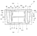
- FIG. 1 is a side view showing an outline of the reactor according to the first embodiment.
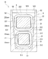
- FIG. 2 is a sectional view showing an outline of the reactor taken along the line (II)-(II) of FIG.
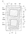
- FIG. 3 is a sectional view showing an outline of the reactor according to the second embodiment.
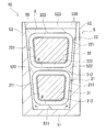
- FIG. 4 is a cross-sectional view showing the outline of the reactor according to the third embodiment.
- the space for installing the reactor may be so small that the pair of winding parts cannot be placed flat.
- stacking in the direction orthogonal to the installation surface may be referred to as vertical stacking.
- the distance between the side surface of the upper winding portion and the side wall portion of the case facing the side surface is smaller than that of the lower winding portion. It becomes larger than the distance between the side surface of the winding portion and the side wall portion of the case.
- the inner wall surface of the side wall portion of the case is usually formed with an inclined surface that is inclined from the inner bottom surface of the bottom plate portion of the case toward the opposite side so as to be away from each other at a distance facing each other.
- the case is typically manufactured by die casting such as die casting or injection molding.
- the inclined surface of the inner wall surface is formed by transferring a draft provided in the mold for releasing the case from the mold when the case is manufactured.
- the case for accommodating the pair of vertically stacked winding portions is deeper than the case for accommodating the pair of flatly arranged winding portions. The deeper the case, the larger the distance between the side surface of the upper winding part and the inner wall surface of the case.
- the gap between the side surface of the upper winding part and the inner wall surface of the case becomes large, so that the upper winding part is less likely to radiate through the inner wall surface of the case. That is, the lower winding portion is easily cooled, and the upper winding portion is difficult to cool. As a result, when the temperature of the upper winding portion becomes higher than that of the lower winding portion, the loss of the reactor increases.
- one of the purposes of the present disclosure is to provide a reactor with a small installation area and low loss.
- the reactor according to the present disclosure has a small installation area and low loss.
- a reactor according to an aspect of the present disclosure is A reactor comprising a combination of a coil and a magnetic core, a case that houses the combination, and a sealing resin portion that is filled inside the case and seals at least a part of the combination.
- the case is An inner bottom surface on which the combination is placed, A pair of coil facing surfaces facing the side surface of the coil, The pair of coil facing surfaces has an inclined surface that is inclined from the inner bottom surface side toward the opposite side of the inner bottom surface so as to be apart from each other,
- the coil is A first winding portion arranged on the inner bottom surface side, A second winding portion arranged on the side opposite to the inner bottom surface side of the first winding portion, The first winding portion and the second winding portion are vertically stacked so that their axes are parallel to each other, The width of the second winding portion is larger than the width of the first winding portion.
- the installation area is smaller than that in the case where the first winding part and the second winding part are placed flat. small.
- the length of the combination along the direction orthogonal to both the parallel direction of the first winding part and the second winding part and the axial direction of the coil is such that the first winding part and the second winding part are This is because it is smaller than the length of the combination along the parallel direction of the parts.
- the above reactor has low loss.
- the height of each of the first winding portion and the second winding portion is constant, by making the width of the second winding portion larger than the width of the first winding portion, Compared with the case where the second winding portion has the same width, the distance between the side surface of the second winding portion and the inclined surface facing the side surface is likely to be smaller. Therefore, the second winding portion is likely to radiate heat. Therefore, the first winding portion and the second winding portion are likely to be uniformly cooled via the coil facing surface of the case. The uniform cooling of the first winding portion and the second winding portion easily reduces the maximum temperature of the coil. Reducing the maximum coil temperature tends to reduce reactor loss.
- the definition of the width of the winding portion will be described later.
- the above reactor can reduce the cost.
- the reason is that it is possible to easily dissipate heat in the second winding portion simply by making the width of the second winding portion larger than the width of the first winding portion as described above. This is because it does not need to be made of high resin or the like.
- a resin having a high thermal conductivity easily radiates heat from the second winding portion even if the distance between the side surface of the second winding portion and the inclined surface is large to some extent, but the cost is relatively high.
- the inner bottom surface is a flat surface, Each end face shape of the first winding portion and the second winding portion, It has a rectangular frame shape, A pair of case facing sides that extend in the vertical direction and that face each of the inclined surfaces, A pair of connecting sides connecting one end side and the other end side of the pair of case facing sides, The pair of connecting sides may be parallel to the inner bottom surface.
- the distance between each side surface and each inclined surface of the first winding portion along the width direction gradually increases from the inner bottom surface side to the opposite side.
- the distance between each side surface and each inclined surface of the second winding portion along the width direction gradually increases from the inner bottom surface side to the opposite side.
- Each end face shape of the first winding portion and the second winding portion It has a rectangular frame shape, One case facing side that is parallel to and faces one of the inclined surfaces, It is possible to have the other case facing side that is non-parallel and that faces the other inclined surface.
- the above reactor has even lower loss.
- the distance between the one side surface of the first winding portion and the one inclined surface can be made uniform from the inner bottom surface side to the opposite side.
- the distance between the one side surface and the one inclined surface of the second winding portion can be made uniform from the inner bottom surface side to the opposite side.
- the reactor has a uniform spacing between one side surface of the first winding portion and one inclined surface and a spacing between one side surface of the second winding portion and one inclined surface.
- the second winding portion can easily dissipate heat from one side surface thereof.
- one side surface of the first winding portion and one side surface of the second winding portion are brought into surface contact with one inclined surface, if necessary. Therefore, in the reactor described above, the second winding portion can more easily dissipate heat from one side surface thereof.
- the interval along the width direction between the other side surface of the first winding portion and the other inclined surface gradually increases from the inner bottom surface side to the opposite side.
- the distance between the other side surface and the other inclined surface of the second winding portion along the width direction gradually increases from the inner bottom surface side to the opposite side.
- the distance along the width direction between each side surface and each inclined surface of the first winding portion and the distance along the width direction between the side surface and the inclined surface of the second winding portion are It is possible to make them uniform from the bottom side to the opposite side. Therefore, in the reactor described above, the second winding portion can easily dissipate heat from the other side surface. Therefore, the reactor described above can easily uniformly cool the first winding portion and the second winding portion via the coil facing surfaces of the case.
- Each end face shape of the first winding portion and the second winding portion It has a trapezoidal frame shape, It can be mentioned that the case has a pair of case facing sides that face each of the inclined surfaces and are parallel to each other.
- the above reactor has even lower loss.
- the distance between the one side surface of the first winding portion and the one inclined surface, and the distance between the other side surface of the first winding portion and the other inclined surface from the inner bottom surface side to the opposite side. Can be made uniform.
- interval between each side surface of each 2nd winding part and each inclined surface can be made uniform. Therefore, the first winding portion and the second winding portion are likely to be uniformly cooled via the coil facing surfaces of the case.
- the magnetic core has a first inner core portion and a second inner core portion arranged inside the first winding portion and the second winding portion,
- the cross-sectional shape of the first inner core portion and the second inner core portion taken along a cutting plane orthogonal to the magnetic flux in each inner core portion has an inner peripheral shape of the first winding portion and the second winding portion.
- the shape follows
- the width of the second inner core portion may be larger than the width of the first inner core portion.
- the cross-sectional shape of the first inner core is a shape along the inner peripheral shape of the first winding portion, the distance between the first winding portion and the first inner core portion is It tends to be uniform in the circumferential direction. Similarly, the spacing between the second winding portion and the second inner core portion is likely to be uniform in the circumferential direction of the second inner core portion.
- the width of the second inner core portion is larger than the width of the first inner core portion, and the width of the second winding portion is larger than the width of the first winding portion.
- the gap between the second winding portion and the second inner core portion is likely to be smaller than when the core portion has the same width. Further, the size of the space between the first winding part and the first inner core part and the size of the space between the second winding part and the second inner core part are likely to be the same. Furthermore, if the facing intervals of the inclined surfaces are the same, the width of the second inner core portion can be increased as compared with the case where the first winding portion and the second winding portion have the same width. Therefore, the reactor can increase the inductance.
- An angle formed by the inner bottom surface and each of the inclined surfaces is 91 ° or more and 95 ° or less.
- the case is typically manufactured by die casting such as die casting or injection molding.
- the inclined surface is formed by transferring a draft provided in the mold for releasing the case from the mold when the case is manufactured. If the angle is 91 ° or more, the first winding portion and the second winding portion have the same width, and when the first winding portion and the second winding portion are vertically stacked, the second winding on the upper stage side The distance between the side surface of the winding portion and the inclined surface tends to be larger than the distance between the side surface of the second winding portion on the lower stage side and the inclined surface.
- the width of the second winding portion is larger than the width of the first winding portion, it is possible to reduce the distance between the side surface and the inclined surface of the second winding portion on the upper stage side. Therefore, even if they are stacked vertically, the second winding portion is likely to radiate heat through the side wall portion of the case. If the angle is 95 ° or less, the angle is not too large. Therefore, the difference in width between the first winding portion and the second winding portion is not too large. Therefore, it is unlikely that a difference occurs in the heat generation characteristics of the second winding portion and the first winding portion.
- the reactor 1A includes a combined body 10 in which the coil 2 and the magnetic core 3 are combined, a case 5, and a sealing resin portion 8.
- the case 5 includes a bottom plate portion 51 on which the combined body 10 is placed, and a side wall portion 52 that surrounds the outer periphery of the combined body 10.
- the pair of coil facing surfaces 521 facing the side surface of the coil 2 in the side wall portion 52 have inclined surfaces 522 that are inclined from the bottom plate portion 51 side toward the opposite side of the bottom plate portion 51 so as to be separated from each other.
- the sealing resin portion 8 is filled inside the case 5 and seals at least a part of the combined body 10.
- the coil 2 has a first winding portion 21 and a second winding portion 22 formed by winding a winding.
- the first winding portion 21 is arranged on the bottom plate portion 51 side.
- the second winding portion 22 is arranged on the side opposite to the bottom plate portion 51 side of the first winding portion 21.
- the first winding portion 21 and the second winding portion 22 are vertically stacked so that their axes are parallel to each other.
- One of the features of the reactor 1A is that the width of the second winding portion 22 is larger than the width of the first winding portion 21. The following description will be made in the order of the main characteristic part of the reactor 1A, the structure of the part related to the characteristic part, the main effect, and each structure.
- the direction along the vertical direction is the depth direction of the case 5. 1 and 2, the upper side of the paper surface is the upper side and the lower side of the paper surface is the lower side.
- the direction along this vertical direction is called the height direction or the vertical direction.
- the direction orthogonal to both the height direction and the axial direction of the coil 2 is called the width direction.
- the left-right direction of the paper surface is the width direction.
- the case 5 houses the combination 10 inside.
- the case 5 can protect the combination 10 mechanically and from the external environment. The protection from the external environment improves the corrosion resistance of the combination 10. Moreover, the case 5 can dissipate heat from the combination 10.
- the case 5 is a bottomed cylindrical container.
- the case 5 includes a bottom plate portion 51 and a side wall portion 52. In FIG. 1, for convenience of explanation, the illustration of the side wall portion on the front side of the drawing is omitted.
- the bottom plate portion 51 and the side wall portion 52 are integrally formed in this example.
- the bottom plate portion 51 and the side wall portion 52 may be individually molded.
- the bottom plate portion 51 and the side wall portion 52 may be integrated with each other by screwing or the like.
- An opening 55 is formed on the upper end side of the side wall 52.
- the inner space surrounded by the bottom plate portion 51 and the side wall portion 52 has a shape and size capable of accommodating the entire combined body 10.
- the bottom plate portion 51 has an inner bottom surface 511 on which the combined body 10 is placed, and an outer bottom surface to be installed on an installation target such as a cooling base. Illustration of the installation target is omitted.
- the bottom plate portion 51 has a rectangular flat plate shape. The inner bottom surface 511 and the outer bottom surface are flat in this example.
- the side wall portion 52 surrounds the outer periphery of the combined body 10.
- the side wall portion 52 is provided upright on the peripheral edge of the bottom plate portion 51.
- the side wall 52 has a rectangular frame shape in this example.
- the height of the side wall portion 52 is higher than the height of the combined product 10.
- the inner wall surface 520 of the side wall portion 52 has four surfaces, a pair of coil facing surfaces 521 and a pair of core facing surfaces 523 (FIG. 1).
- the pair of coil facing surfaces 521 face each other.
- the pair of core facing surfaces 523 face each other.
- the facing direction of the pair of coil facing surfaces 521 and the facing direction of the pair of core facing surfaces 523 are orthogonal to each other.
- Each coil facing surface 521 faces the side surface of the coil 2. That is, each coil facing surface 521 faces the first winding portion 21 and the second winding portion 22.
- the side surfaces of the first winding part 21 and the second winding part 22 are the outer circumferences of the first winding part 21 and the second winding part 22 of the first winding part 21 and the second winding part 22, respectively.
- Each coil facing surface 521 has an inclined surface 522 that is inclined from the inner bottom surface 511 side of the case 5 toward the opening 55 side so as to be separated from each other.
- a groove portion into which the end surface member 41 is fitted may be formed at a position facing the end surface member 41 of the holding member 4 described later, in the depth direction of the case 5. Illustration of the groove is omitted. If the groove is formed, the combination 10 of the coil 2, the magnetic core 3 and the holding member 4 can be easily positioned with respect to the case 5.
- each core facing surface 523 faces the outer end surface of the outer core portion 33.
- the outer end surface of the outer core portion 33 is a surface of the outer core portion 33 opposite to the first inner core portion 31 and the second inner core portion 32.
- each core facing surface 523 has an inclined surface 524 that is inclined so as to be away from the inner bottom surface 511 side of the case 5 toward the opening 55 side.
- the case 5 is typically manufactured by die casting such as die casting or injection molding.
- the inclined surfaces 522 and 524 are formed by transferring the draft angle provided in the mold for releasing the case 5 from the mold when the case 5 is manufactured.
- the angle (angle ⁇ ) formed by each of the inclined surface 522 and the inclined surface 524 and the inner bottom surface 511 is preferably 91 ° or more and 95 ° or less (FIGS. 1 and 2). 1 and 2, the inclination angles of the inclined surface 522 and the inclined surface 524 are exaggerated for convenience of description.
- the angles formed by the inclined surface 522 and the inclined surface 524 and the inner bottom surface 511 are all the same in this example.
- the angle formed by the inclined surface 522 and the inner bottom surface 511 and the angle formed by the inclined surface 524 and the inner bottom surface 511 may be different from each other.
- the mold releasability of Case 5 is high. If the angle ⁇ is 91 ° or more, the widths of the first winding portion 21 and the second winding portion 22 are the same, and the axes of the first winding portion 21 and the second winding portion 22 are parallel to each other.
- the space between the side surface of the second winding portion 22 on the upper stage side and the inclined surface 522 is the same as the side surface of the second winding portion 22 on the lower stage side. It tends to be larger than the distance between the inclined surface 522 and the inclined surface 522.
- the direction orthogonal to the inner bottom surface 511 is the depth direction of the case 5.
- stacking in the depth direction of the case 5 may be referred to as vertical stacking.
- the width of the second winding portion 22 larger than the width of the first winding portion 21, the gap between the side surface of the second winding portion 22 on the upper stage side and the inclined surface 522. Can be made smaller. Therefore, the second winding portion 22 is likely to radiate heat via the side wall portion 52 of the case 5 even if the above-mentioned products are stacked vertically.
- the angle ⁇ is 95 ° or less, the angle is not too large. Therefore, the difference between the width of the first winding portion 21 and the width of the second winding portion 22 is not too large. Therefore, the difference in heat generation characteristics between the second winding portion 22 and the first winding portion 21 is unlikely to occur.
- Examples of the material of the case 5 include a non-magnetic metal and a non-metal material.
- the non-magnetic metal include aluminum and its alloys, magnesium and its alloys, copper and its alloys, silver and its alloys, and austenitic stainless steel. The thermal conductivity of these non-magnetic metals is relatively high. Therefore, the case 5 can be used as a heat dissipation path, and the heat generated in the combination 10 can be efficiently dissipated to an installation target such as a cooling base. Therefore, the reactor 1A can improve heat dissipation.
- die casting can be preferably used as a method of forming the case 5.
- non-metal material examples include resins such as polybutylene terephthalate (PBT) resin, urethane resin, polyphenylene sulfide (PPS) resin, and acrylonitrile-butadiene-styrene (ABS) resin.
- PBT polybutylene terephthalate
- PPS polyphenylene sulfide
- ABS acrylonitrile-butadiene-styrene
- the resin may contain a ceramics filler. Examples of the ceramic filler include alumina and silica. Resins containing these ceramic fillers are excellent in heat dissipation and electrical insulation.
- injection molding can be preferably used as a method of forming the case 5.
- the bottom plate portion 51 and the side wall portion 52 are individually molded, the bottom plate portion 51 and the side wall portion 52 may be made of different materials.
- the first winding portion 21 and the second winding portion 22 included in the coil 2 are hollow cylindrical bodies formed by spirally winding separate windings.
- the first winding portion 21 and the second winding portion 22 are rectangular tubular bodies.
- the first winding portion 21 and the second winding portion 22 can also be formed by a single winding.
- the first winding portion 21 and the second winding portion 22 are electrically connected to each other. The method of electrical connection will be described later.
- a covered wire having an insulating coating on the outer circumference of the conductor wire can be used.
- the material of the conductor wire include copper, aluminum, magnesium, and alloys thereof.
- Examples of the conductor wire include a rectangular wire and a round wire.
- Examples of the insulating coating include enamel.
- a typical example of the enamel is polyamide-imide.
- a coated rectangular wire whose conductor wire is a copper rectangular wire and whose insulating coating is enamel is used.
- the first winding part 21 and the second winding part 22 are constituted by an edgewise coil obtained by edgewise winding the coated rectangular wire.
- the cross-sectional areas of the windings of the first winding portion 21 and the second winding portion 22 are the same in this example.
- the first winding part 21 and the second winding part 22 are wound in the same direction.
- the first winding part 21 and the second winding part 22 have the same number of turns.
- the cross-sectional area and the number of turns of the windings of the first winding portion 21 and the second winding portion 22 may be different from each other.
- the first winding part 21 and the second winding part 22 are arranged vertically in the depth direction of the case 5 so that their axes are parallel to each other. This parallel does not include the same straight line.
- the first winding portion 21 is arranged on the bottom plate portion 51 side.
- the second winding portion 22 is arranged above the first winding portion 21, that is, on the side opposite to the bottom plate portion 51 side.
- the end face shapes of the first winding part 21 and the second winding part 22 are rectangular frame shapes (FIG. 2).
- the rectangular frame shape here includes a square frame shape.
- the corners of the first winding portion 21 and the second winding portion 22 are rounded.
- the end surface shapes of the first winding portion 21 and the second winding portion 22 may be trapezoidal frame shapes or the like. Examples of the trapezoidal frame shape include an isosceles trapezoidal frame shape (FIG. 4) and a right-angled trapezoidal frame shape described later. Illustration of a right-angled trapezoidal frame is omitted.
- the end face shape of the first winding portion 21 has a pair of case facing sides 211 and a pair of connecting sides 212 (FIG. 2).
- the pair of case facing sides 211 face the inclined surfaces 522 of the coil facing surfaces 521 of the side wall portion 52.
- the pair of connecting sides 212 connects one end side and the other end side of the pair of case facing sides 211.
- the pair of case facing sides 211 are parallel to the depth direction of the case 5.
- Each connecting side 212 is parallel to the inner bottom surface 511 of the bottom plate portion 51.
- Each connecting side 212 extends along the width direction of the case 5.
- the end face shape of the second winding portion 22 has a pair of case facing sides 221 and a pair of connecting sides 222 (FIG. 2).
- the pair of case facing sides 221 face the inclined surfaces 522 of the coil facing surfaces 521 of the side wall portion 52.
- the pair of connecting sides 222 connects one end side and the other end side of the pair of case facing sides 221.
- the pair of case facing sides 221 are parallel to the depth direction of the case 5.
- Each connecting side 222 is parallel to the inner bottom surface 511 of the bottom plate portion 51.
- Each connection side 222 extends along the width direction of the case 5.
- the heights of the first winding portion 21 and the second winding portion 22 are the same in this example. That is, the length of the pair of case facing sides 211 of the first winding portion 21 and the length of the pair of case facing sides 221 of the second winding portion 22 are the same. The heights of the first winding portion 21 and the second winding portion 22 may be different from each other.
- the width of the second winding part 22 is larger than the width of the first winding part 21. That is, the length of the pair of connecting sides 222 in the second winding portion 22 is longer than the length of the pair of connecting sides 212 in the first winding portion 21.
- FIG. 2 exaggerates the magnitude relationship between the widths of the first winding portion 21 and the second winding portion 22.
- the width of the second winding portion 22 is preferably a length that satisfies both the following condition (1) and condition (2).
- the minimum distance D2min along the width direction between each side surface of the second winding portion 22 and each inclined surface 522 is between each side surface of the first winding portion 21 and each inclined surface 522. It is not more than the minimum distance D1min along the width direction.
- the maximum distance D2max along the width direction between each side surface of the second winding portion 22 and each inclined surface 522 is between each side surface of the first winding portion 21 and each inclined surface 522. It is less than or equal to the maximum distance D1max along the width direction.
- the width of the second winding portion 22 is a length that satisfies both the condition (1) and the condition (2), the second winding portion 22 is likely to radiate heat via the side wall portion 52 of the case 5. Therefore, the first winding portion 21 and the second winding portion 22 are likely to be uniformly cooled via the side wall portion 52 of the case 5. Even cooling of the first winding portion 21 and the second winding portion 22 facilitates reduction of the maximum temperature of the coil 2. By reducing the maximum temperature of the coil 2, the loss of the reactor 1A is easily reduced.
- the width of the second winding portion 22 is such that the minimum distance D2min is smaller than the minimum distance D1min and the maximum distance D2max is smaller than the maximum distance D1max. Is preferred.
- the second winding portion 22 is more likely to generate heat with higher resistance than the first winding portion 21. Since the width of the second winding portion 22 is larger than the width of the first winding portion 21, the total length of the conductor of the second winding portion 22 is longer than the total length of the conductor of the first winding portion 21. is there. Therefore, if the minimum distance D2min ⁇ the minimum distance D1min and the maximum distance D2max ⁇ the maximum distance D1max are satisfied, the second winding portion 22, which is more likely to generate heat, is likely to be effectively radiated. Therefore, the second winding portion 22 and the first winding portion 21 are likely to be cooled uniformly.
- the distance between each side surface of the first winding portion 21 and each inclined surface 522 along the width direction gradually increases from the inner bottom surface 511 side to the opening 55 side.
- the distance between each side surface of the second winding portion 22 and each inclined surface 522 along the width direction gradually increases from the inner bottom surface 511 side to the opening 55 side.
- the minimum distance D1min is the distance between the inner bottom surface 511 side and each inclined surface 522 on each side surface of the first winding portion 21 along the width direction.
- the maximum gap D1max is a gap along the width direction between the opening 55 side and each inclined surface 522 on each side surface of the first winding portion 21.
- the minimum distance D2min is a distance along the width direction between the inner bottom surface 511 side and each inclined surface 522 on each side surface of the second winding portion 22.
- the maximum distance D2max is a distance along the width direction between the opening 55 side and each inclined surface 522 on each side surface of the second winding portion 22.
- the minimum distance D1min and the minimum distance D2min are substantially the same.
- the maximum distance D1max and the maximum distance D2max are substantially the same. Therefore, the second winding portion 22 and the first winding portion 21 are likely to be uniformly cooled via the side wall portion 52 of the case 5.
- the magnetic core 3 includes a first inner core portion 31, a second inner core portion 32, and a pair of outer core portions 33 (FIG. 1).
- the first inner core portion 31 and the second inner core portion 32 are arranged inside the first winding portion 21 and the second winding portion 22, respectively.
- the first inner core portion 31 and the second inner core portion 32 mean portions of the magnetic core 3 along the axial direction of the first winding portion 21 and the second winding portion 22.
- both ends of the magnetic core 3 along the axial direction of the first winding part 21 and the second winding part 22 are located outside the first winding part 21 and the second winding part 22.
- the protruding portion is also a part of the first inner core portion 31 and the second inner core portion 32.
- the pair of outer core portions 33 are arranged outside the first winding portion 21 and the second winding portion 22. That is, in the outer core portion 33, the coil 2 is not arranged, but the outer core portion 33 is projected from the coil 2 and is exposed from the coil 2.
- the magnetic core 3 is formed in an annular shape by contacting the end surfaces of the first inner core portion 31 and the second inner core portion 32 with the inner end surface of the outer core portion 33. That is, the pair of outer core portions 33 are arranged so as to sandwich the first inner core portion 31 and the second inner core portion 32 which are arranged separately. The first inner core portion 31, the second inner core portion 32, and the pair of outer core portions 33 form a closed magnetic circuit when the coil 2 is excited.
- the shapes of the first inner core portion 31 and the second inner core portion 32 are preferably shapes along the inner peripheral shapes of the first winding portion 21 and the second winding portion 22. This is because the distance between the inner peripheral surface of the first winding portion 21 and the outer peripheral surface of the first inner core portion 31 tends to be uniform in the circumferential direction of the first inner core portion 31. In addition, the distance between the inner peripheral surface of the second winding portion 22 and the outer peripheral surface of the second inner core portion 32 is likely to be uniform in the circumferential direction of the second inner core portion 32. In this example, the shapes of the first inner core portion 31 and the second inner core portion 32 are rectangular parallelepiped. The corner portions of the first inner core portion 31 and the second inner core portion 32 are rounded along the inner peripheral surfaces of the corner portions of the first winding portion 21 and the second winding portion 22.
- the height of the first inner core portion 31 and the height of the second inner core portion 32 are the same in this example.
- the width of the second inner core portion 32 is preferably larger than the width of the first inner core portion 31. If the width of the second inner core portion 32 is larger than the width of the first inner core portion 31, the width of the second winding portion 22 is larger than the width of the first winding portion 21. This is because the gap between the inner peripheral surface of the second winding portion 22 and the outer peripheral surface of the second inner core portion 32 is likely to be smaller than in the case where the first inner core portion 31 and the first inner core portion 31 have the same width. .
- the size of the gap between the inner peripheral surface of the first winding portion 21 and the outer peripheral surface of the first inner core portion 31, and the inner peripheral surface of the second winding portion 22 and the outer periphery of the second inner core portion 32 is likely to be the same as each other. Further, if the facing intervals of the inclined surfaces 522 are the same, the width of the second inner core portion 32 should be made larger than that in the case where the first winding portion 21 and the second winding portion 22 have the same width. You can Therefore, the inductance can be increased.
- the width of the first inner core portion 31 and the width of the second inner core portion 32 in this example is the size of the interval between the inner peripheral surface of the first winding portion 21 and the outer peripheral surface of the first inner core portion 31. And the size of the interval between the inner peripheral surface of the second winding portion 22 and the outer peripheral surface of the second inner core portion 32 are the same.
- the first inner core portion 31 and the second inner core portion 32 of this example are composed of one columnar core piece.
- the core pieces do not go through the gap.
- the core piece has a length of substantially the entire axial length of the first winding portion 21 and the second winding portion 22.
- the first inner core portion 31 and the second inner core portion 32 may be configured by a laminated body in which a plurality of columnar core pieces and gaps are laminated and arranged along the axial direction of the coil 2.
- Examples of the shape of the outer core portion 33 include a rectangular parallelepiped shape and a quadrangular pyramid shape.
- the rectangular parallelepiped shape is a columnar body in which the outer end surface, the side surface, the upper surface, and the lower surface of the outer core portion 33 are all rectangular. The areas of the upper surface and the lower surface are the same.
- the quadrangular pyramid shape is, for example, a columnar body in which the outer end surface, the upper surface, and the lower surface of the outer core portion 33 are rectangular, and the side surfaces are rectangular trapezoidal.
- a columnar body in which the outer end surface of the outer core portion 33 has an isosceles trapezoidal shape and the side surfaces, the upper surface, and the lower surface have rectangular shapes can be used.
- the outer end surface of the outer core portion 33 may have an isosceles trapezoidal shape, the side surfaces thereof may have a right-angled trapezoidal shape, and the upper and lower surfaces may have a rectangular columnar shape.
- the columnar body in which the outer end surface of the outer core portion 33 has an isosceles trapezoidal shape can be suitably used when the width of the second inner core portion 32 is wider than the width of the first inner core portion 31.
- the area of the upper surface of the quadrangular pyramid-shaped outer core portion 33 is larger than the area of the lower surface.
- the outer core portion 33 in this example has a truncated pyramid shape.
- the outer core portion 33 may be a columnar body in which the outer end surface, the upper surface, and the lower surface have a rectangular shape, and the side surfaces have a right-angled trapezoidal shape (FIG. 1).
- the outer end surface of the outer core portion 33 is preferably configured as a surface parallel to the inclined surface 524 of the core facing surface 523. The reason is that the outer end surface of the outer core portion 33 and the inclined surface 524 of the core facing surface 523 can be brought into surface contact with each other. Due to this surface contact, the heat of the outer core portion 33 is easily transferred to the side wall portion 52 of the case 5. Therefore, the heat dissipation of the magnetic core 3 tends to be high. Moreover, the pair of outer core portions 33 can be pressed in the directions in which they approach each other. Therefore, the magnetic core 3 is less likely to be displaced with respect to the case 5.
- the upper surface of the outer core portion 33 is substantially flush with the upper surface of the second inner core portion 32 in this example.
- the lower surface of the outer core portion 33 is substantially flush with the lower surface of the first inner core portion 31 in this example.
- the upper surface of the outer core portion 33 may be higher than the upper surface of the second inner core portion 32.
- the lower surface of the outer core portion 33 may be below the lower surface of the first inner core portion 31.
- the sealing resin part 8 is filled in the case 5 and covers at least a part of the combined body 10.
- the sealing resin portion 8 transfers the heat of the combined body 10 to the case 5, mechanically protects the combined body 10 and protects it from the external environment, improves the corrosion resistance of the combined body 10, and between the combined body 10 and the case 5.
- Various functions such as improvement of the electric insulation property, integration of the combined body 10 and improvement of strength and rigidity of the reactor 1A by integrating the combined body 10 and the case 5.
- the encapsulating resin portion 8 of the present example embeds substantially the entire assembly 10.
- the sealing resin portion 8 has a portion interposed between the coil 2 and the case 5.
- the encapsulation resin portion 8 is provided between the lower surface of the first winding portion 21 and the inner bottom surface 511 of the bottom plate portion 51, the side surface of the first winding portion 21 and the coil facing surface 521 of the side wall portion 52. In between, it is interposed between the side surface of the second winding portion 22 and the coil facing surface 521.
- the sealing resin portion 8 is also interposed between the upper surface of the first winding portion 21 and the lower surface of the second winding portion 22. The heat of the first winding portion 21 and the second winding portion 22 is easily transferred to the case 5 via the sealing resin portion 8.
- thermosetting resin and the thermoplastic resin may be used as the material of the sealing resin portion 8.
- thermosetting resin include epoxy resin, urethane resin, silicone resin, unsaturated polyester resin and the like.
- thermoplastic resin include PPS resin and the like. These resins may contain the above-mentioned ceramic filler and the like.
- the reactor 1A according to the first embodiment can achieve the following effects.
- the length of the combined body 10 along the direction orthogonal to both the parallel direction of the first winding portion 21 and the second winding portion 22 and the axial direction of the coil 2 is determined by the length of the first winding portion 21 and the second winding portion. This is because it is smaller than the length of the combined product 10 along the parallel direction of the turning portions 22.
- the width of the second winding portion 22 is made larger than the width of the first winding portion 21.
- the distance between the side surface of the second winding portion 22 and the inclined surface 522 facing the side surface is likely to be small. Therefore, the second winding portion 22 is likely to dissipate heat.
- the minimum distance D2min is substantially the same as the minimum distance D1min
- the maximum distance D2max is substantially the same as the maximum distance D1max.
- first winding portion 21 and the second winding portion 22 are likely to be uniformly cooled via the side wall portion 52 of the case 5. Even cooling of the first winding portion 21 and the second winding portion 22 facilitates reduction of the maximum temperature of the coil 2. Therefore, reduction of the maximum temperature of the coil 2 tends to reduce loss of the reactor 1A.
- the conductors at the ends on the one end side of the coil 2 in the axial direction are directly connected to each other.
- the conductors are connected by bending the ends of the winding of the first winding part 21 and extending to the ends of the winding of the second winding part 22.
- the conductors may be connected to each other via a connecting member that is independent of the first winding portion 21 and the second winding portion 22.
- the connecting member is made of, for example, the same member as the winding.
- the conductors can be connected by welding or pressure welding.
- both ends of each winding on the other end side in the axial direction of the coil 2 are extended upward from the opening 55 of the case 5, although not shown.
- the insulating coating is peeled off to expose the conductor.
- a terminal member is connected to the exposed conductor.
- the coil 2 is connected to an external device such as a power source for supplying electric power to the coil 2 via the terminal member. Illustration of the terminal member and the external device is omitted.
- the first winding part 21 and the second winding part 22 may be individually integrated by an integrated resin. Illustration of the integrated resin is omitted.
- the integrated resin covers the outer peripheral surface, the inner peripheral surface, and the end surface of the first winding portion 21 and the second winding portion 22, and joins adjacent turns.
- a resin having a coating layer of heat-sealing resin formed on the outer circumference of the winding is used, and the winding can be wound and then heated to melt the coating layer.
- the outer circumference of the winding refers to a further outer circumference of the insulating coating of the winding.
- the heat fusion resin include thermosetting resins such as epoxy resin, silicone resin and unsaturated polyester.
- the first inner core portion 31, the second inner core portion 32, and the outer core portion 33 are made of a powder compact or a composite material.
- the powder compact is formed by compression molding soft magnetic powder.
- the powder compact can have a higher proportion of the soft magnetic powder in the core piece as compared with the composite material. Therefore, the green compact is easy to enhance the magnetic properties.
- the magnetic characteristics include relative permeability and saturation magnetic flux density.
- the composite material is formed by dispersing soft magnetic powder in resin.
- the composite material can be obtained by filling a mold with a fluid material in which soft magnetic powder is dispersed in an unsolidified resin and curing the resin.
- the composite material can easily adjust the content of the soft magnetic powder in the resin. Therefore, the composite material is easy to adjust the magnetic characteristics.
- the composite material is easier to form even in a complicated shape as compared with the powder compact.
- the first inner core portion 31, the second inner core portion 32, and the outer core portion 33 may be a hybrid core in which the outer periphery of the powder compact is covered with the composite material.
- the first inner core portion 31 and the second inner core portion 32 are made of a composite material.
- the pair of outer core portions 33 are formed of a powder compact.
- the soft magnetic powder particles include soft magnetic metal particles, coated particles having an insulating coating around the soft magnetic metal particles, and soft magnetic non-metal particles.
- soft magnetic metals include pure iron and iron-based alloys.
- iron-based alloys include Fe-Si alloys and Fe-Ni alloys.
- the insulating coating include phosphate.
- soft magnetic non-metals include ferrite.
- a thermosetting resin or a thermoplastic resin can be used as the resin of the composite material.
- the thermosetting resin include epoxy resin, phenol resin, silicone resin and urethane resin.
- the thermoplastic resin include PPS resin, polyamide (PA) resin, liquid crystal polymer (LCP), polyimide resin, and fluororesin.
- PA resin examples include nylon 6, nylon 66, nylon 9T and the like. These resins may contain the above-mentioned ceramics filler.
- the gap is made of a material having a smaller relative magnetic permeability than the first inner core portion 31, the second inner core portion 32, and the outer core portion 33.
- the relative magnetic permeability of the first inner core portion 31 and the second inner core portion 32 is preferably 5 or more and 50 or less, more preferably 10 or more and 30 or less, and particularly preferably 20 or more and 30 or less.
- the relative magnetic permeability of the outer core portion 33 preferably satisfies at least twice the relative magnetic permeability of the first inner core portion 31 and the second inner core portion 32.
- the relative magnetic permeability of the outer core portion 33 is preferably 50 or more and 500 or less.
- the combined body 10 may include the holding member 4 (FIG. 1).
- the holding member 4 ensures insulation between the coil 2 and the magnetic core 3.
- the holding member 4 of this example has a pair of end surface members 41.
- the end surface member 41 ensures insulation between each end surface of the coil 2 and each outer core portion 33.
- the shape of each end surface member 41 is the same.
- Each end surface member 41 is a frame-shaped plate member in which two through holes 410 are provided along the stacking direction of the first winding portion 21 and the second winding portion 22.
- the first inner core portion 31 and the second inner core portion 32 are fitted into the respective through holes 410.
- the width of the through hole 410 into which the second inner core portion 32 is fitted is larger than the width of the through hole 410 into which the first inner core portion 31 is fitted.
- Two recesses 411 for accommodating the end faces of the first winding portion 21 and the second winding portion 22 are formed on the coil 2 side surface of each end surface member 41.
- Each of the recesses 411 on the coil 2 side makes the entire end surfaces of the first winding portion 21 and the second winding portion 22 come into surface contact with the end surface member 41.
- Each recess 411 is formed in a rectangular ring shape so as to surround the through hole 410.
- the holding member 4 may further include an inner member.
- the inner member ensures insulation between the inner peripheral surfaces of the first winding portion 21 and the second winding portion 22 and the outer peripheral surfaces of the first inner core portion 31 and the second inner core portion 32.
- Examples of the material of the holding member 4 include insulating materials such as various resins.
- the resin for example, the same resin as the resin of the composite material described above can be used.
- the other thermoplastic resin include polytetrafluoroethylene (PTFE) resin, PBT resin, ABS resin and the like.
- PTFE polytetrafluoroethylene
- other thermosetting resins include unsaturated polyester resins.
- the material of the holding member 4 is preferably the same as that of the sealing resin portion 8. This is because the holding member 4 and the sealing resin portion 8 can have the same linear expansion coefficient, and damage to each member due to thermal expansion and contraction can be suppressed.
- the combination 10 may include a mold resin portion.
- the mold resin portion covers each outer core portion 33 and extends inside the first winding portion 21 and the second winding portion 22.
- the mold resin portion covers a region of the outer peripheral surface of each outer core portion 33, excluding a connecting surface between the first inner core portion 31 and the second inner core portion 32.
- the mold resin portion is formed between each outer core portion 33 and the recess 412 of each end surface member 41, the outer peripheral surfaces of the first inner core portion 31 and the second inner core portion 32, and the through hole 410 of each end surface member 41. And the inner peripheral surfaces of the first winding portion 21 and the second winding portion 22 and the outer peripheral surfaces of the first inner core portion 31 and the second inner core portion 32.
- This mold resin portion can integrate each outer core portion 33, each end surface member 41, first inner core portion 31, second inner core portion 32, first winding portion 21, and second winding portion 22.
- the material of the mold resin portion for example, the same thermosetting resin or thermoplastic resin as the resin of the composite material described above can be used.
- These resins may contain the above-mentioned ceramics filler. The inclusion of the ceramics filler can improve the heat dissipation of the mold resin portion.
- the reactor 1A can be used as a component of a circuit that performs a voltage boosting operation or a voltage dropping operation.
- the reactor 1A can be used as, for example, various converters, components of a power conversion device, or the like.
- the converter include a vehicle-mounted converter mounted in a vehicle such as a hybrid vehicle, a plug-in hybrid vehicle, an electric vehicle, a fuel cell vehicle, and a converter for an air conditioner.
- a DC-DC converter is typically used as the in-vehicle converter.
- FIG. 3 is a sectional view showing a state in which the reactor 1B is cut at the same position as the sectional view shown in FIG.
- One case facing side 211 of the first winding portion 21 is parallel to the one inclined surface 522.
- the other case facing side 211 of the first winding portion 21 is not parallel to the other inclined surface 522.
- the pair of connecting sides 212 of the first winding portion 21 is not parallel to the inner bottom surface 511.
- the pair of connecting sides 212 is orthogonal to the one inclined surface 522 and intersects the other inclined surface 522 in a non-orthogonal manner.
- one case facing side 221 of the second winding portion 22 is parallel to the one inclined surface 522.
- the other case facing side 221 of the second winding portion 22 is not parallel to the other inclined surface 522.
- the pair of connecting sides 222 of the second winding portion 22 is not parallel to the inner bottom surface 511.
- the pair of connecting sides 222 is orthogonal to the one inclined surface 522 and intersects the other inclined surface 522 in a non-orthogonal manner.
- the length of the pair of case facing sides 211 of the first winding portion 21 and the length of the pair of case facing sides 221 of the second winding portion 22 are the same.
- the length of the pair of connecting sides 222 in the second winding portion 22 is longer than the length of the pair of connecting sides 212 in the first winding portion 21.
- the distance between the one side surface of the first winding portion 21 and the one inclined surface 522 can be made uniform from the inner bottom surface 511 side to the opening 55 side (the right side of the paper surface of FIG. 3). Similarly, the distance between the one side surface of the second winding portion 22 and the one inclined surface 522 can be made uniform from the inner bottom surface 511 side to the opening 55 side. Then, the distance between the one side surface of the first winding portion 21 and the one inclined surface 522 and the distance between the one side surface of the second winding portion 22 and the one inclined surface 522 are mutually uniform. Can be Therefore, the first winding portion 21 and the second winding portion 22 are likely to be uniformly cooled via the side wall portion 52 of the case 5.
- one side surface of the first winding portion 21 and one side surface of the second winding portion 22 are in surface contact with the one inclined surface 522 (on the right side of FIG. 3). Therefore, the first winding part 21 and the second winding part 22 are more easily cooled.
- a space is provided between one side surface of the first winding portion 21 and the second winding portion 22 and the one inclined surface 522.
- One side surface of the two-winding portion 22 and one inclined surface 522 are in direct contact with each other.
- the other side surface of the first winding portion 21 and the other side surface of the second winding portion 22 are not in contact with the other inclined surface 522 (the left side of the paper surface of FIG. 3).
- a predetermined space is provided between the other side surface of the first winding portion 21 and the other inclined surface 522 and between the other side surface of the second winding portion 22 and the other inclined surface 522. ing.
- the distance between the other side surface of the first winding portion 21 and the other inclined surface 522 gradually increases from the inner bottom surface 511 side to the opening 55 side.
- the distance between the other side surface of the second winding portion 22 and the other inclined surface 522 gradually increases from the inner bottom surface 511 side to the opening 55 side.
- the minimum distance D1min is a distance along the width direction between the inner bottom surface 511 side and the other inclined surface 522 on the other side surface of the first winding portion 21.
- the maximum gap D1max is a gap along the width direction between the opening 55 side and the other inclined surface 522 on the other side surface of the first winding portion 21.
- the minimum distance D2min is a distance along the width direction between the inner bottom surface 511 side and the other inclined surface 522 on the other side surface of the second winding portion 22.
- the maximum distance D2max is a distance along the width direction between the opening 55 side and the other inclined surface 522 on the other side surface of the second winding portion 22.
- the minimum distance D1min and the minimum distance D2min are substantially the same.
- the maximum distance D1max and the maximum distance D2max are substantially the same. Therefore, the second winding portion 22 is likely to dissipate heat. Therefore, the first winding portion 21 and the second winding portion 22 are likely to be uniformly cooled via the side wall portion 52 of the case 5.
- the reactor 1B preferably includes a pedestal portion 9.
- the pedestal portion 9 is arranged on the inner bottom surface 511 of the bottom plate portion 51.
- the pedestal portion 9 mounts the first winding portion 21 and the second winding portion 22 in an inclined state with respect to the inner bottom surface 511 of the bottom plate portion 51.
- the pedestal part 9 makes one case facing side 211 of the first winding part 21 and one case facing side 221 of the second winding part 22 parallel to the one inclined surface 522. That is, the upper surface of the pedestal portion 9 of this example is a surface along the direction orthogonal to the one inclined surface 522.
- the pedestal portion 9 of this example is composed of a member different from the case 5.
- the pedestal portion 9 is composed of a sheet-shaped member that supports substantially the entire lower surface of the first winding portion 21.
- the sectional shape of the pedestal portion 9 is a right-angled trapezoid.
- the upper surface of the pedestal portion 9 is formed as an inclined surface.
- the height of the pedestal portion 9 gradually increases from one inclined surface 522 side toward the other inclined surface 522 side.
- the pedestal portion 9 may be configured by a ridge member that supports one end side in the width direction on the lower surface of the first winding portion 21 in the axial direction of the first winding portion 21.
- the pedestal portion 9 can be configured by a part of the case 5.
- the inner bottom surface 511 may be formed of the inclined surface.
- the same non-magnetic metal or non-metallic material as that of the case 5 can be mentioned. If the pedestal portion 9 is made of these materials, the heat of the first winding portion 21 is easily transferred to the bottom plate portion 51 of the case 5 via the pedestal portion 9. Therefore, the first winding portion 21 is easily cooled.
- the pedestal portion 9 may be made of a non-magnetic metal sheet coated with a non-metal material. Then, the insulation between the first winding portion 21 and the case 5 tends to be high.
- the reactor 1B according to the second embodiment has low loss.
- the first winding part 21 and the second winding part 22 are arranged so as to be inclined so that one side surface of the first winding part 21 and the second winding part 22 and one inclined surface 522 are in surface contact with each other. This is because the second winding portion 22 is more easily cooled from the one side surface thereof.
- the minimum distance D2min is substantially the same as the minimum distance D1min
- the maximum distance D2max is substantially the same as the maximum distance D1max. Therefore, the second winding portion 22 is easily radiated from the other side surface. Therefore, the first winding portion 21 and the second winding portion 22 are likely to be uniformly cooled via the side wall portion 52 of the case 5, so that the maximum temperature of the coil 2 is easily reduced.
- FIG. 4 is a sectional view showing a state in which the reactor 1C is cut at the same position as the sectional view shown in FIG.
- the end face shapes of the first winding portion 21 and the second winding portion 22 are trapezoidal frame shapes which are equal to each other.
- the corners of the first winding portion 21 and the second winding portion 22 are rounded.
- the end face shape of the first winding portion 21 has a pair of case facing sides 211 and a pair of connecting sides 212.
- One case facing side 211 is parallel to the one inclined surface 522.
- the other case facing side 211 is parallel to the other inclined surface 522.
- Each connecting side 212 is parallel to the inner bottom surface 511 of the bottom plate portion 51.
- Each connecting side 212 extends along the width direction of the case 5. That is, the angle (angle ⁇ ) formed between each case facing side 211 and the lower connecting side 212 is the same as the angle (angle ⁇ ) formed between the inner bottom surface 511 and the inclined surface 522.
- the end face shape of the second winding portion 22 has a pair of case facing sides 221 and a pair of connecting sides 222.
- One case facing side 221 is parallel to the one inclined surface 522.
- the other case facing side 221 is parallel to the other inclined surface 522.
- Each connecting side 222 is parallel to the inner bottom surface 511 of the bottom plate portion 51.
- Each connecting side 212 extends along the width direction of the case 5. That is, the angle (angle ⁇ ) formed between each case facing side 221 and the lower connecting side 222 is the same as the angle (angle ⁇ ) formed between the inner bottom surface 511 and the inclined surface 522.
- the heights of the first winding portion 21 and the second winding portion 22 are the same in this example.
- the length of the pair of case facing sides 211 of the first winding portion 21 and the length of the pair of case facing sides 221 of the second winding portion 22 are the same.
- the width of the second winding part 22 is larger than the width of the first winding part 21.
- the width being large means that the width of the second winding portion 22 on the inner bottom surface 511 side is larger than the width of the first winding portion 21 on the opening 55 side. That is, the length of the lower connecting side 222 of the second winding portion 22 is longer than the length of the upper connecting side 212 of the first winding portion 21.
- the distance between the one side surface of the first winding portion 21 and the one inclined surface 522 is uniform from the inner bottom surface 511 side to the opening 55 side.
- the distance between the other side surface of the first winding portion 21 and the other inclined surface 522 is uniform from the inner bottom surface 511 side to the opening 55 side.
- the distance between the one side surface of the first winding portion 21 and the one inclined surface 522 and the distance between the other side surface of the first winding portion 21 and the other inclined surface 522 are substantially equal to each other. It is the same.
- the distance between the one side surface of the second winding portion 22 and the one inclined surface 522 is uniform from the inner bottom surface 511 side to the opening 55 side.
- the interval between the other side surface of the second winding portion 22 and the other inclined surface 522 is uniform from the inner bottom surface 511 side to the opening 55 side.
- the distance between the one side surface of the second winding portion 22 and the one inclined surface 522 and the distance between the other side surface of the second winding portion 22 and the other inclined surface 522 are substantially equal to each other. It is the same.
- each side surface of the first winding portion 21 and each inclined surface 522 and the distance between each side surface of the second winding portion 22 and each inclined surface 522 are substantially the same.
- the shape of the first inner core portion 31 and the second inner core portion 32 is an isosceles trapezoidal columnar body along the inner peripheral shape of the first winding portion 21 and the second winding portion 22, respectively.
- the interval between the first winding portion 21 and the first inner core portion 31 is uniform in the circumferential direction of the first inner core portion 31.
- the distance between the second winding portion 22 and the second inner core portion 32 is uniform in the circumferential direction of the second inner core portion 32.
- the height of the first inner core portion 31 and the height of the second inner core portion 32 are the same.
- the width of the second inner core portion 32 is larger than the width of the first inner core portion 31.
- the width of the second inner core portion 32 being larger means that the width of the second inner core portion 32 on the inner bottom surface 511 side is larger than the width of the first inner core portion 31 on the opening 55 side.
- the width of the first inner core portion 31 and the width of the second inner core portion 32 in this example are the size of the gap between the first winding portion 21 and the first inner core portion 31, and the second winding portion.
- the size of the gap between the second inner core portion 32 and the second inner core part 32 is substantially the same.
- the reactor 1C according to the third embodiment has a much lower loss than the reactor 1A according to the first embodiment.
- the distance between each side surface of the first winding portion 21 and each inclined surface 522 and the distance between each side surface of the second winding portion 22 and each inclined surface 522 are uniform, and Since the distance between each side surface of the turning portion 21 and each inclined surface 522 and the distance between each side surface of the second winding portion 22 and each inclined surface 522 are substantially the same, This is because the winding part 22 is more easily cooled. Therefore, the first winding portion 21 and the second winding portion 22 are likely to be uniformly cooled via the side wall portion 52 of the case 5, so that the maximum temperature of the coil 2 is easily reduced. Further, in the reactor 1C according to the third embodiment, when the facing intervals of the inclined surfaces 522 of the case 5 are the same, it is easier to reduce the dead space in the case 5 as compared with the reactor 1A according to the first embodiment.
- the present invention is not limited to these exemplifications, and is shown by the scope of the claims, and is intended to include meanings equivalent to the scope of the claims and all modifications within the scope.
- the end surface shapes of the first winding portion and the second winding portion may be different from each other.
- the end surface shape of the first winding portion may be a rectangular frame shape
- the end surface shape of the second winding portion may be a trapezoidal frame shape such as an isosceles trapezoidal shape.
Abstract
コイルと磁性コアとの組合体と、前記組合体を内部に収納するケースと、前記ケースの内部に充填されて前記組合体の少なくとも一部を封止する封止樹脂部とを備えるリアクトルであって、前記ケースは、前記組合体が載置される内底面と、前記コイルの側面に対向する一対のコイル対向面とを有し、前記一対のコイル対向面は、前記内底面側から前記内底面の反対側に向かって互いの距離が離れるように傾斜する傾斜面を有し、前記コイルは、前記内底面側に配置される第一巻回部と、前記第一巻回部の前記内底面側とは反対側に配置される第二巻回部とを備え、前記第一巻回部と前記第二巻回部とは、互いの軸が平行となるように縦積みされ、前記第二巻回部の幅が、前記第一巻回部の幅よりも大きい、リアクトル。
Description
本開示は、リアクトルに関する。
本出願は、2018年10月26日付の日本国出願の特願2018-202370に基づく優先権を主張し、前記日本国出願に記載された全ての記載内容を援用するものである。
本出願は、2018年10月26日付の日本国出願の特願2018-202370に基づく優先権を主張し、前記日本国出願に記載された全ての記載内容を援用するものである。
特許文献1のリアクトルは、コイルと磁性コアとの組合体と、ケースと、封止樹脂部とを備える。ケースは、組合体を内部に収納する。このケースは、組合体が載置される底板部と、組合体の外周を囲む側壁部とを有する。底板部と側壁部とは、一体に成形されている。コイルは、一対の巻回部を有する。一対の巻回部の形状は、互いに矩形状である。一対の巻回部の幅及び高さは、互いに同一である。この一対の巻回部は、互いの軸が平行となるように底板部の同一平面上に横並びに配置されている。以下の説明では、同一平面上に横並びに配置することを平置きということがある。磁性コアは、各巻回部の内部に配置される内側コア部と、各巻回部の外部に配置される外側コア部とを有する。封止樹脂部は、ケースの内部に充填され、組合体を封止する。
本開示に係るリアクトルは、
コイルと磁性コアとの組合体と、前記組合体を内部に収納するケースと、前記ケースの内部に充填されて前記組合体の少なくとも一部を封止する封止樹脂部とを備えるリアクトルであって、
前記ケースは、
前記組合体が載置される内底面と、
前記コイルの側面に対向する一対のコイル対向面とを有し、
前記一対のコイル対向面は、前記内底面側から前記内底面の反対側に向かって互いの距離が離れるように傾斜する傾斜面を有し、
前記コイルは、
前記内底面側に配置される第一巻回部と、
前記第一巻回部の前記内底面側とは反対側に配置される第二巻回部とを備え、
前記第一巻回部と前記第二巻回部とは、互いの軸が平行となるように縦積みされ、
前記第二巻回部の幅が、前記第一巻回部の幅よりも大きい。
[本開示が解決しようとする課題]
リアクトルの設置対象によっては、リアクトルの設置スペースが小さくて、一対の巻回部を平置きできない場合がある。小さな設置スペースにリアクトルを設置するために、例えば、一対の巻回部を互いの軸が平行となるように設置面と直交方向に積層することが考えられる。以下の説明では、設置面と直交方向に積層することを縦積みということがある。
リアクトルの設置対象によっては、リアクトルの設置スペースが小さくて、一対の巻回部を平置きできない場合がある。小さな設置スペースにリアクトルを設置するために、例えば、一対の巻回部を互いの軸が平行となるように設置面と直交方向に積層することが考えられる。以下の説明では、設置面と直交方向に積層することを縦積みということがある。
しかし、ケースの底板部に対して、同一幅の一対の巻回部を縦積みすれば、上段の巻回部の側面とその側面に対向するケースの側壁部との間の間隔が、下段の巻回部の側面とケースの側壁部との間の間隔に比較して大きくなる。ケースの側壁部の内壁面には、通常、ケースの底板部の内底面からその反対側に向かって互いに対向する距離が離れるように傾斜する傾斜面が形成されている。ケースは、代表的には、ダイキャストなどの金型鋳造や射出成形により製造される。内壁面の傾斜面は、ケースの製造時、金型からケースを離型させるために金型に設けられる抜き勾配が転写されることで形成される。縦積みする一対の巻回部を収納するケースの深さは、平置きする一対の巻回部を収納するケースの深さに比較して深い。ケースの深さが深いほど、上段の巻回部の側面とケースの内壁面との間の間隔は大きくなる。
上段の巻回部の側面とケースの内壁面との間の間隔が大きくなることで、ケースの内壁面を介して上段の巻回部が放熱され難くなる。即ち、下段の巻回部は冷却し易く、上段の巻回部は冷却し難い。その結果、上段の巻回部が下段の巻回部に比べて高温になると、リアクトルの損失が大きくなる。
そこで、本開示は、設置面積が小さくて、低損失なリアクトルを提供することを目的の一つとする。
[本開示の効果]
本開示に係るリアクトルは、設置面積が小さくて、低損失である。
本開示に係るリアクトルは、設置面積が小さくて、低損失である。
《本開示の実施形態の説明》
最初に本開示の実施態様を列記して説明する。
最初に本開示の実施態様を列記して説明する。
(1)本開示の一形態に係るリアクトルは、
コイルと磁性コアとの組合体と、前記組合体を内部に収納するケースと、前記ケースの内部に充填されて前記組合体の少なくとも一部を封止する封止樹脂部とを備えるリアクトルであって、
前記ケースは、
前記組合体が載置される内底面と、
前記コイルの側面に対向する一対のコイル対向面とを有し、
前記一対のコイル対向面は、前記内底面側から前記内底面の反対側に向かって互いの距離が離れるように傾斜する傾斜面を有し、
前記コイルは、
前記内底面側に配置される第一巻回部と、
前記第一巻回部の前記内底面側とは反対側に配置される第二巻回部とを備え、
前記第一巻回部と前記第二巻回部とは、互いの軸が平行となるように縦積みされ、
前記第二巻回部の幅が、前記第一巻回部の幅よりも大きい。
上記のリアクトルは、第一巻回部と第二巻回部とを縦積みしているため、第一巻回部と第二巻回部とを平置きする場合に比較して、設置面積が小さい。一般的に、第一巻回部と第二巻回部の並列方向とコイルの軸方向との両方向に直交する方向に沿った組合体の長さが、第一巻回部と第二巻回部の並列方向に沿った組合体の長さよりも小さいからである。
また、上記のリアクトルは、低損失である。第一巻回部と第二巻回部のそれぞれの高さを一定としたとき、第二巻回部の幅を第一巻回部の幅よりも大きくすることで、第一巻回部と第二巻回部とを同一幅とする場合に比較して、第二巻回部の側面とその側面に対向する傾斜面との間の間隔が小さくなり易い。そのため、第二巻回部が放熱され易い。よって、ケースのコイル対向面を介して第一巻回部と第二巻回部とが均等に冷却され易い。この第一巻回部と第二巻回部の均等な冷却により、コイルの最高温度が低減され易い。コイルの最高温度の低減により、リアクトルの損失が低減され易い。巻回部の幅の定義は後述する。
更に、上記のリアクトルは、低コスト化を図れる。その理由は、上述のように第二巻回部の幅を第一巻回部の幅よりも大きくするだけで第二巻回部を放熱させ易くできるため、封止樹脂部を熱伝導率の高い樹脂などで構成しなくてもよいからである。熱伝導率の高い樹脂は、第二巻回部の側面と傾斜面との間の間隔がある程度大きくても第二巻回部を放熱させ易いが、比較的コストが高い。
そして、上記のリアクトルは、ケースの傾斜面の対向間隔を同一としたとき、ケース内におけるデッドスペースを少なくし易い。
(2)上記リアクトルの一形態として、
前記内底面は平面であり、
前記第一巻回部及び前記第二巻回部の各端面形状は、
矩形枠状であり、
前記各傾斜面に対向し縦方向に伸びる一対のケース対向辺と、
前記一対のケース対向辺の一端側同士及び他端側同士を連結する一対の連結辺とを有し、
前記一対の連結辺が前記内底面に平行であることが挙げられる。
前記内底面は平面であり、
前記第一巻回部及び前記第二巻回部の各端面形状は、
矩形枠状であり、
前記各傾斜面に対向し縦方向に伸びる一対のケース対向辺と、
前記一対のケース対向辺の一端側同士及び他端側同士を連結する一対の連結辺とを有し、
前記一対の連結辺が前記内底面に平行であることが挙げられる。
上記の構成によれば、第一巻回部の各側面と各傾斜面との間の幅方向に沿った間隔は、内底面側からその反対側にわたって漸次大きくなっている。同様に、第二巻回部の各側面と各傾斜面との間の幅方向に沿った間隔は、内底面側からその反対側にわたって漸次大きくなっている。第一巻回部の各側面と各傾斜面との間の幅方向に沿った間隔と、第二巻回部の各側面と各傾斜面との間の幅方向に沿った間隔とを、内底面側からその反対側にわたって互いに均一にすることができる。そのため、ケースの各コイル対向面を介して第二巻回部と第一巻回部とが均等に冷却され易い。
(3)上記リアクトルの一形態として、
前記第一巻回部及び前記第二巻回部の各端面形状は、
矩形枠状であり、
一方の前記傾斜面に対向し、かつ平行な一方のケース対向辺と、
他方の前記傾斜面に対向し、かつ非平行な他方のケース対向辺とを有することが挙げられる。
前記第一巻回部及び前記第二巻回部の各端面形状は、
矩形枠状であり、
一方の前記傾斜面に対向し、かつ平行な一方のケース対向辺と、
他方の前記傾斜面に対向し、かつ非平行な他方のケース対向辺とを有することが挙げられる。
上記のリアクトルは、より一層低損失である。
上記のリアクトルは、第一巻回部の一方の側面と一方の傾斜面との間の間隔を、内底面側からその反対側にわたって均一にすることができる。同様に、上記のリアクトルは、第二巻回部の一方の側面と一方の傾斜面との間の間隔を、内底面側からその反対側にわたって均一にすることができる。そして、上記のリアクトルは、第一巻回部の一方の側面と一方の傾斜面との間の間隔と、第二巻回部の一方の側面と一方の傾斜面との間の間隔とを均一にすることができる。そのため、上記のリアクトルは、第二巻回部をその一方の側面から放熱させ易い。更に、上記のリアクトルは、必要に応じて、第一巻回部の一方の側面と第二巻回部の一方の側面とを一方の傾斜面に面接触させられる。そのため、上記のリアクトルは、第二巻回部をその一方の側面からより一層放熱させ易い。
また、第一巻回部の他方の側面と他方の傾斜面との間の幅方向に沿った間隔は、内底面側からその反対側にわたって漸次大きくなっている。同様に、第二巻回部の他方の側面と他方の傾斜面との間の幅方向に沿った間隔は、内底面側からその反対側にわたって漸次大きくなっている。そして、第一巻回部の各側面と各傾斜面との間の幅方向に沿った間隔と、第二巻回部の側面と傾斜面との間の幅方向に沿った間隔とは、内底面側からその反対側にわたって互いに均一にすることができる。そのため、上記のリアクトルは、第二巻回部をその他方の側面からも放熱させ易い。よって、上記のリアクトルは、ケースの各コイル対向面を介して第一巻回部と第二巻回部とを均等に冷却し易い。
(4)上記リアクトルの一形態として、
前記第一巻回部及び前記第二巻回部の各端面形状は、
台形枠状であり、
前記各傾斜面に対向し、かつ平行な一対のケース対向辺を有することが挙げられる。
前記第一巻回部及び前記第二巻回部の各端面形状は、
台形枠状であり、
前記各傾斜面に対向し、かつ平行な一対のケース対向辺を有することが挙げられる。
上記のリアクトルは、より一層低損失である。第一巻回部の一方の側面と一方の傾斜面との間の間隔と、第一巻回部の他方の側面と他方の傾斜面との間の間隔とを、内底面側からその反対側にわたって均一にすることができる。同様に、第二巻回部の一方の側面と一方の傾斜面との間の間隔と、第二巻回部の他方の側面と他方の傾斜面との間の間隔とを、内底面側からその反対側にわたって均一にすることができる。そして、第一巻回部の各側面と各傾斜面との間の間隔と、第二巻回部の各側面と各傾斜面との間の間隔とを均一にすることができる。よって、第一巻回部と第二巻回部とは、ケースの各コイル対向面を介して均等に冷却され易い。
(5)上記リアクトルの一形態として、
前記磁性コアは、前記第一巻回部及び前記第二巻回部の内部に配置される第一内側コア部及び第二内側コア部を有し、
前記第一内側コア部及び前記第二内側コア部を前記各内側コア部内の磁束に直交する切断面で切断した断面形状は、前記第一巻回部及び前記第二巻回部の内周形状に沿った形状であり、
前記第二内側コア部の幅は、前記第一内側コア部の幅よりも大きいことが挙げられる。
前記磁性コアは、前記第一巻回部及び前記第二巻回部の内部に配置される第一内側コア部及び第二内側コア部を有し、
前記第一内側コア部及び前記第二内側コア部を前記各内側コア部内の磁束に直交する切断面で切断した断面形状は、前記第一巻回部及び前記第二巻回部の内周形状に沿った形状であり、
前記第二内側コア部の幅は、前記第一内側コア部の幅よりも大きいことが挙げられる。
第一内側コアの上記断面形状が第一巻回部の内周形状に沿った形状であることで、第一巻回部と第一内側コア部との間の間隔が第一内側コア部の周方向にわたって均一になり易い。同様に、第二巻回部と第二内側コア部との間の間隔が第二内側コア部の周方向にわたって均一になり易い。
第二内側コア部の幅が第一内側コア部の幅よりも大きいことで、第二巻回部の幅が第一巻回部の幅よりも大きいため、第二内側コア部と第一内側コア部とが同一幅の場合に比較して、第二巻回部と第二内側コア部との間の間隔が小さくなり易い。また、第一巻回部と第一内側コア部との間の間隔の大きさと、第二巻回部と第二内側コア部との間の間隔の大きさとが、互いに同一になり易い。更に、傾斜面の対向間隔が同一であれば、第一巻回部と第二巻回部とが同一幅の場合に比較して、第二内側コア部の幅を大きくすることができる。そのため、上記のリアクトルは、インダクタンスを増加できる。
(6)上記リアクトルの一形態として、
前記内底面と前記各傾斜面とのなす角が、91°以上95°以下であることが挙げられる。
前記内底面と前記各傾斜面とのなす角が、91°以上95°以下であることが挙げられる。
上記角度が91°以上であれば、ケースの離型性が高くなる。ケースは、代表的には、ダイキャストなどの金型鋳造や射出成形により製造される。傾斜面は、ケースの製造時、金型からケースを離型させるために金型に設けられる抜き勾配が転写されることで形成される。上記角度が91°以上であれば、第一巻回部と第二巻回部の幅を同一として、第一巻回部と第二巻回部とを縦積みした場合、上段側の第二巻回部の側面と傾斜面との間の間隔は、下段側の第二巻回部の側面と傾斜面との間の間隔に比較して大きくなり易い。しかし、第二巻回部の幅を第一巻回部の幅よりも大きくすることで、上段側の第二巻回部の側面と傾斜面との間の間隔を小さくすることができる。そのため、縦積みしても、ケースの側壁部を介して第二巻回部が放熱され易い。上記角度が95°以下であれば、上記角度が過度に大き過ぎない。そのため、第一巻回部と第二巻回部の幅の差が大き過ぎない。よって、第二巻回部と第一巻回部の発熱特性に差が生じ難い。
《本開示の実施形態の詳細》
本開示の実施形態の詳細を、以下に図面を参照しつつ説明する。図中の同一符号は同一名称物を示す。
本開示の実施形態の詳細を、以下に図面を参照しつつ説明する。図中の同一符号は同一名称物を示す。
《実施形態1》
〔リアクトル〕
図1、図2を参照して、実施形態1に係るリアクトル1Aを説明する。リアクトル1Aは、コイル2と磁性コア3とを組み合わせた組合体10と、ケース5と、封止樹脂部8とを備える。ケース5は、組合体10を載置する底板部51と、組合体10の外周を囲む側壁部52とを備える。側壁部52におけるコイル2の側面と対向する一対のコイル対向面521は、底板部51側から底板部51の反対側に向かって互いの距離が離れるように傾斜する傾斜面522を有する。封止樹脂部8は、ケース5の内部に充填されて組合体10の少なくとも一部を封止する。コイル2は、巻線を巻回してなる第一巻回部21及び第二巻回部22を有する。第一巻回部21は、底板部51側に配置される。第二巻回部22は、第一巻回部21の底板部51側とは反対側に配置される。第一巻回部21と第二巻回部22とは、互いの軸が平行となるように縦積みされている。リアクトル1Aの特徴の一つは、第二巻回部22の幅が第一巻回部21の幅よりも大きい点にある。以下の説明は、リアクトル1Aの主たる特徴部分、特徴部分に関連する部分の構成、主要な効果、各構成の順に行う。また、以下の説明は、ケース5の底板部51側を下とし、底板部51側とは反対側を上として行う。即ち、この上下方向に沿った方向がケース5の深さ方向である。図1,図2では、紙面の上側が上であり、紙面の下側が下である。この上下方向に沿った方向を高さ方向や縦方向という。この高さ方向とコイル2の軸方向との両方向に直交する方向を幅方向という。図2では、紙面の左右方向が幅方向である。
[主たる特徴部分及び関連する部分の構成]
(ケース)
ケース5は、内部に組合体10を収納する。ケース5は、組合体10の機械的保護及び外部環境からの保護を図ることができる。外部環境からの保護によって、組合体10の防食性が向上する。その上、ケース5は、組合体10を放熱できる。ケース5は、有底筒状の容器である。ケース5は、底板部51と側壁部52とを備える。図1は、説明の便宜上、紙面手前の側壁部の図示を省略している。底板部51と側壁部52とは、本例では一体に成形されている。なお、底板部51と側壁部52とは、個々に成形されていてもよい。その場合、底板部51と側壁部52とは、互いにねじ止めするなどして一体化することが挙げられる。側壁部52の上端側には、開口部55が形成されている。底板部51と側壁部52とで囲まれる内部空間は、組合体10の全体を収納可能な形状及び大きさを有する。
〈底板部〉
底板部51は、組合体10が載置される内底面511と、冷却ベースなどの設置対象に設置する外底面とを有する。設置対象の図示は省略する。底板部51は、矩形平板状である。内底面511及び外底面は、本例では平面で構成されている。
底板部51は、組合体10が載置される内底面511と、冷却ベースなどの設置対象に設置する外底面とを有する。設置対象の図示は省略する。底板部51は、矩形平板状である。内底面511及び外底面は、本例では平面で構成されている。
〈側壁部〉
側壁部52は、組合体10の外周を囲む。側壁部52は、底板部51の周縁に立設される。側壁部52の形状は、本例では矩形枠状である。側壁部52の高さは、組合体10の高さよりも高い。側壁部52の内壁面520は、一対のコイル対向面521と一対のコア対向面523との4つの面を有する(図1)。一対のコイル対向面521は、互いに対向している。一対のコア対向面523は、互いに対向している。一対のコイル対向面521の対向方向と一対のコア対向面523の対向方向とは互いに直交する。
側壁部52は、組合体10の外周を囲む。側壁部52は、底板部51の周縁に立設される。側壁部52の形状は、本例では矩形枠状である。側壁部52の高さは、組合体10の高さよりも高い。側壁部52の内壁面520は、一対のコイル対向面521と一対のコア対向面523との4つの面を有する(図1)。一対のコイル対向面521は、互いに対向している。一対のコア対向面523は、互いに対向している。一対のコイル対向面521の対向方向と一対のコア対向面523の対向方向とは互いに直交する。
・コイル対向面
各コイル対向面521は、コイル2の側面に対向する。即ち、各コイル対向面521は、第一巻回部21及び第二巻回部22に対向する。第一巻回部21及び第二巻回部22の側面とは、第一巻回部21及び第二巻回部22の外周面のうち第一巻回部21及び第二巻回部22の幅方向に位置する面をいう。各コイル対向面521は、ケース5の内底面511側から開口部55側に向かって互いの距離が離れるように傾斜する傾斜面522を有する。コイル対向面521の傾斜面522のうち、後述する保持部材4の端面部材41との対向箇所には、ケース5の深さ方向にわたって端面部材41をはめ込む溝部が形成されていてもよい。上記溝部の図示は省略する。上記溝部が形成されていれば、コイル2と磁性コア3と保持部材4との組合体10をケース5に対して位置決めし易い。
各コイル対向面521は、コイル2の側面に対向する。即ち、各コイル対向面521は、第一巻回部21及び第二巻回部22に対向する。第一巻回部21及び第二巻回部22の側面とは、第一巻回部21及び第二巻回部22の外周面のうち第一巻回部21及び第二巻回部22の幅方向に位置する面をいう。各コイル対向面521は、ケース5の内底面511側から開口部55側に向かって互いの距離が離れるように傾斜する傾斜面522を有する。コイル対向面521の傾斜面522のうち、後述する保持部材4の端面部材41との対向箇所には、ケース5の深さ方向にわたって端面部材41をはめ込む溝部が形成されていてもよい。上記溝部の図示は省略する。上記溝部が形成されていれば、コイル2と磁性コア3と保持部材4との組合体10をケース5に対して位置決めし易い。
・コア対向面
コア対向面523は、外側コア部33の外端面に対向する。外側コア部33の外端面とは、外側コア部33における第一内側コア部31及び第二内側コア部32側とは反対側の面をいう。各コア対向面523は、コイル対向面521と同様、ケース5の内底面511側から開口部55側に向かって互いの距離が離れるように傾斜する傾斜面524を有する。
コア対向面523は、外側コア部33の外端面に対向する。外側コア部33の外端面とは、外側コア部33における第一内側コア部31及び第二内側コア部32側とは反対側の面をいう。各コア対向面523は、コイル対向面521と同様、ケース5の内底面511側から開口部55側に向かって互いの距離が離れるように傾斜する傾斜面524を有する。
ケース5は、代表的には、ダイキャストなどの金型鋳造や射出成形により製造される。傾斜面522,524は、ケース5の製造時、金型からケース5を離型させるために金型に設けられる抜き勾配が転写されることで形成される。
・傾斜角度
傾斜面522及び傾斜面524のそれぞれと内底面511とのなす角(角度α)は、91°以上95°以下が好ましい(図1,図2)。図1,図2は、説明の便宜上、傾斜面522及び傾斜面524の傾斜角度を誇張して示している。傾斜面522及び傾斜面524のそれぞれと内底面511とのなす角は、本例では全て同一としている。なお、傾斜面522と内底面511とのなす角と、傾斜面524と内底面511とのなす角とが、互いに異なっていてもよい。
傾斜面522及び傾斜面524のそれぞれと内底面511とのなす角(角度α)は、91°以上95°以下が好ましい(図1,図2)。図1,図2は、説明の便宜上、傾斜面522及び傾斜面524の傾斜角度を誇張して示している。傾斜面522及び傾斜面524のそれぞれと内底面511とのなす角は、本例では全て同一としている。なお、傾斜面522と内底面511とのなす角と、傾斜面524と内底面511とのなす角とが、互いに異なっていてもよい。
上記角度αが91°以上であれば、ケース5の離型性が高くなる。上記角度αが91°以上であれば、第一巻回部21と第二巻回部22の幅を同一として、第一巻回部21と第二巻回部22とを互いの軸が平行となるように内底面511に直交する方向に積層した場合、上段側の第二巻回部22の側面と傾斜面522との間の間隔は、下段側の第二巻回部22の側面と傾斜面522との間の間隔に比較して大きくなり易い。ここでいう内底面511に直交する方向とは、ケース5の深さ方向である。以下の説明では、このケース5の深さ方向に積層することを縦積みということがある。しかし、後述するように第二巻回部22の幅を第一巻回部21の幅よりも大きくすることで、上段側の第二巻回部22の側面と傾斜面522との間の間隔を小さくすることができる。そのため、上記縦積みしても、ケース5の側壁部52を介して第二巻回部22が放熱され易い。上記角度αが95°以下であれば、角度が過度に大き過ぎない。そのため、第一巻回部21の幅と第二巻回部22の幅との差が大き過ぎない。よって、第二巻回部22と第一巻回部21の発熱特性に差が生じ難い。
〈材質〉
ケース5の材質は、非磁性金属や非金属材料が挙げられる。非磁性金属としては、アルミニウムやその合金、マグネシウムやその合金、銅やその合金、銀やその合金、オーステナイト系ステンレス鋼などが挙げられる。これらの非磁性金属の熱伝導率は比較的高い。そのため、ケース5は、放熱経路として利用でき、組合体10に発生した熱を冷却ベースなどの設置対象に効率良く放熱できる。よって、リアクトル1Aは、放熱性を高められる。金属でケース5を形成する場合、ケース5の形成方法としては、ダイキャストが好適に利用できる。非金属材料としては、ポリブチレンテレフタレート(PBT)樹脂、ウレタン樹脂、ポリフェニレンスルフィド(PPS)樹脂、アクリロニトリル-ブタジエン-スチレン(ABS)樹脂などの樹脂が挙げられる。これらの非金属材料は一般に電気絶縁性に優れるものが多い。そのため、これらの非金属材料は、コイル2とケース5との間の絶縁性を高められる。これらの非金属材料は、上述した金属材料よりも軽く、リアクトル1Aを軽量にできる。上記樹脂は、セラミックスフィラーを含有していてもよい。セラミックスフィラーは、例えば、アルミナ、シリカなどが挙げられる。これらのセラミックスフィラーを含有する樹脂は、放熱性及び電気絶縁性に優れる。樹脂でケース5を形成する場合、ケース5の形成方法としては、射出成形が好適に利用できる。底板部51と側壁部52とを個々に成形する場合には、底板部51と側壁部52とが互いに異なる材質で構成されていてもよい。
ケース5の材質は、非磁性金属や非金属材料が挙げられる。非磁性金属としては、アルミニウムやその合金、マグネシウムやその合金、銅やその合金、銀やその合金、オーステナイト系ステンレス鋼などが挙げられる。これらの非磁性金属の熱伝導率は比較的高い。そのため、ケース5は、放熱経路として利用でき、組合体10に発生した熱を冷却ベースなどの設置対象に効率良く放熱できる。よって、リアクトル1Aは、放熱性を高められる。金属でケース5を形成する場合、ケース5の形成方法としては、ダイキャストが好適に利用できる。非金属材料としては、ポリブチレンテレフタレート(PBT)樹脂、ウレタン樹脂、ポリフェニレンスルフィド(PPS)樹脂、アクリロニトリル-ブタジエン-スチレン(ABS)樹脂などの樹脂が挙げられる。これらの非金属材料は一般に電気絶縁性に優れるものが多い。そのため、これらの非金属材料は、コイル2とケース5との間の絶縁性を高められる。これらの非金属材料は、上述した金属材料よりも軽く、リアクトル1Aを軽量にできる。上記樹脂は、セラミックスフィラーを含有していてもよい。セラミックスフィラーは、例えば、アルミナ、シリカなどが挙げられる。これらのセラミックスフィラーを含有する樹脂は、放熱性及び電気絶縁性に優れる。樹脂でケース5を形成する場合、ケース5の形成方法としては、射出成形が好適に利用できる。底板部51と側壁部52とを個々に成形する場合には、底板部51と側壁部52とが互いに異なる材質で構成されていてもよい。
(コイル)
コイル2に備わる第一巻回部21及び第二巻回部22は、別々の巻線を螺旋状に巻回してなる中空の筒状体である。本形態では、第一巻回部21及び第二巻回部22は、角筒状体である。なお、第一巻回部21及び第二巻回部22は、一本の巻線で形成することもできる。第一巻回部21及び第二巻回部22は、互いに電気的に接続されている。電気的な接続の仕方は後述する。
コイル2に備わる第一巻回部21及び第二巻回部22は、別々の巻線を螺旋状に巻回してなる中空の筒状体である。本形態では、第一巻回部21及び第二巻回部22は、角筒状体である。なお、第一巻回部21及び第二巻回部22は、一本の巻線で形成することもできる。第一巻回部21及び第二巻回部22は、互いに電気的に接続されている。電気的な接続の仕方は後述する。
第一巻回部21及び第二巻回部22を構成する各巻線は、導体線の外周に絶縁被覆を備える被覆線を利用できる。導体線の材質は、銅、アルミニウム、マグネシウム、或いはその合金が挙げられる。導体線の種類は、平角線や丸線が挙げられる。絶縁被覆は、エナメルなどが挙げられる。エナメルとしては、代表的にはポリアミドイミドが挙げられる。本例の各巻線には、導体線が銅製の平角線からなり、絶縁被覆がエナメルからなる被覆平角線を用いている。この被覆平角線をエッジワイズ巻きしたエッジワイズコイルで第一巻回部21及び第二巻回部22が構成されている。第一巻回部21及び第二巻回部22の巻線の断面積は、本例では互いに同一である。第一巻回部21及び第二巻回部22の巻回方向は、互いに同一方向である。第一巻回部21及び第二巻回部22の巻数は、互いに同一数である。なお、第一巻回部21と第二巻回部22の巻線の断面積や巻数が互いに異なっていてもよい。
第一巻回部21及び第二巻回部22の配置は、互いの軸が平行となるようにケース5の深さ方向に縦積みした状態としている。この平行とは、同一直線状は含まない。第一巻回部21は、底板部51側に配置されている。第二巻回部22は、第一巻回部21の上方側、即ち底板部51側とは反対側に配置されている。
第一巻回部21及び第二巻回部22の端面形状は、互いに矩形枠状としている(図2)。ここでいう矩形枠状は、正方形枠状を含む。第一巻回部21及び第二巻回部22の角部は丸めている。なお、第一巻回部21及び第二巻回部22の端面形状は、台形枠状などでもよい。台形枠状としては、後述する等脚台形枠状(図4)や直角台形枠状が挙げられる。直角台形枠状の図示は省略する。
第一巻回部21の端面形状は、一対のケース対向辺211と一対の連結辺212とを有する(図2)。一対のケース対向辺211は、側壁部52の各コイル対向面521の傾斜面522に対向する。一対の連結辺212は、一対のケース対向辺211の一端側同士及び他端側同士を連結する。本例では、一対のケース対向辺211は、ケース5の深さ方向に平行である。各連結辺212は、底板部51の内底面511に平行である。各連結辺212は、ケース5の幅方向に沿っている。同様に、第二巻回部22の端面形状は、一対のケース対向辺221と一対の連結辺222とを有する(図2)。一対のケース対向辺221は、側壁部52の各コイル対向面521の傾斜面522に対向する。一対の連結辺222は、一対のケース対向辺221の一端側同士及び他端側同士を連結する。本例では、一対のケース対向辺221は、ケース5の深さ方向に平行である。各連結辺222は、底板部51の内底面511に平行である。各連結辺222は、ケース5の幅方向に沿っている。
第一巻回部21と第二巻回部22の高さは、本例では互いに同一である。即ち、第一巻回部21における一対のケース対向辺211の長さと、第二巻回部22における一対のケース対向辺221の長さとは、同じ長さである。なお、第一巻回部21及び第二巻回部22の高さは、互いに異ならせてもよい。
第二巻回部22の幅は、第一巻回部21の幅よりも大きい。即ち、第二巻回部22における一対の連結辺222の長さは、第一巻回部21における一対の連結辺212の長さよりも長い。図2は、説明の便宜上、第一巻回部21と第二巻回部22の幅の大小関係を誇張して示している。第二巻回部22の幅は、以下の条件(1)及び条件(2)の両方を満たす長さとすることが好ましい。
(1)第二巻回部22の各側面と各傾斜面522との間の幅方向に沿った最小の間隔D2minが、第一巻回部21の各側面と各傾斜面522との間の幅方向に沿った最小の間隔D1min以下である。
(2)第二巻回部22の各側面と各傾斜面522との間の幅方向に沿った最大の間隔D2maxが、第一巻回部21の各側面と各傾斜面522との間の幅方向に沿った最大の間隔D1max以下である。
(2)第二巻回部22の各側面と各傾斜面522との間の幅方向に沿った最大の間隔D2maxが、第一巻回部21の各側面と各傾斜面522との間の幅方向に沿った最大の間隔D1max以下である。
第二巻回部22の幅が条件(1)及び条件(2)の両方を満たす長さであれば、ケース5の側壁部52を介して第二巻回部22が放熱され易い。そのため、ケース5の側壁部52を介して第一巻回部21と第二巻回部22とが均等に冷却され易い。第一巻回部21と第二巻回部22の均等な冷却により、コイル2の最高温度が低減し易い。コイル2の最高温度の低減により、リアクトル1Aの損失が低減し易い。特に、第二巻回部22の幅が、上記最小の間隔D2minが上記最小の間隔D1minよりも小さく、かつ上記最大の間隔D2maxが上記最大の間隔D1maxよりも小さくなるような長さであることが好ましい。その理由は、第二巻回部22を効果的に放熱させ易いからである。特に、第二巻回部22と第一巻回部21の導体断面積が互いに同一である場合、第二巻回部22は第一巻回部21に比較して高抵抗で発熱し易い。第二巻回部22の幅が第一巻回部21の幅よりも大きいため、第二巻回部22の導体の全長が第一巻回部21の導体の全長に比較して長いからである。そのため、上記最小の間隔D2min<上記最小の間隔D1min、かつ上記最大の間隔D2max<上記最大の間隔D1maxを満たせば、より発熱し易い第二巻回部22が効果的に放熱され易い。よって、第二巻回部22と第一巻回部21とが均等に冷却され易い。
本例では、第一巻回部21の各側面と各傾斜面522との間の幅方向に沿った間隔は、内底面511側から開口部55側にわたって漸次大きくなっている。同様に、第二巻回部22の各側面と各傾斜面522との間の幅方向に沿った間隔は、内底面511側から開口部55側にわたって漸次大きくなっている。
即ち、上記最小の間隔D1minは、第一巻回部21の各側面における内底面511側と各傾斜面522との間の幅方向に沿った間隔である。上記最大の間隔D1maxは、第一巻回部21の各側面における開口部55側と各傾斜面522との間の幅方向に沿った間隔である。同様に、上記最小の間隔D2minは、第二巻回部22の各側面における内底面511側と各傾斜面522との間の幅方向に沿った間隔である。上記最大の間隔D2maxは、第二巻回部22の各側面における開口部55側と各傾斜面522との間の幅方向に沿った間隔である。上記最小の間隔D1minと上記最小の間隔D2minとは、実質的に同一である。上記最大の間隔D1maxと上記最大の間隔D2maxとは、実質的に同一である。そのため、ケース5の側壁部52を介して第二巻回部22と第一巻回部21とが均等に冷却され易い。
(磁性コア)
磁性コア3は、第一内側コア部31及び第二内側コア部32と、一対の外側コア部33とを備える(図1)。
磁性コア3は、第一内側コア部31及び第二内側コア部32と、一対の外側コア部33とを備える(図1)。
第一内側コア部31及び第二内側コア部32はそれぞれ、第一巻回部21及び第二巻回部22の内部に配置される。第一内側コア部31及び第二内側コア部32は、磁性コア3のうち、第一巻回部21及び第二巻回部22の軸方向に沿った部分を意味する。本例では、磁性コア3のうち、第一巻回部21及び第二巻回部22の軸方向に沿った部分の両端部が第一巻回部21及び第二巻回部22の外側に突出しているが、その突出する部分も第一内側コア部31及び第二内側コア部32の一部である。一対の外側コア部33は、第一巻回部21及び第二巻回部22の外部に配置される。即ち、外側コア部33は、コイル2が配置されず、コイル2から突出されて、コイル2から露出される。
磁性コア3は、第一内側コア部31及び第二内側コア部32の端面と外側コア部33の内端面とを接触させて環状に形成される。即ち、離間して配置される第一内側コア部31及び第二内側コア部32を挟むように一対の外側コア部33が配置される。これら第一内側コア部31及び第二内側コア部32と一対の外側コア部33とにより、コイル2を励磁したとき、閉磁路が形成される。
〈内側コア部〉
第一内側コア部31及び第二内側コア部32の形状は、第一巻回部21及び第二巻回部22の内周形状に沿った形状とすることが好ましい。第一巻回部21の内周面と第一内側コア部31の外周面との間の間隔が、第一内側コア部31の周方向にわたって均一になり易いからである。また、第二巻回部22の内周面と第二内側コア部32の外周面との間の間隔が、第二内側コア部32の周方向にわたって均一になり易いからである。本例では、第一内側コア部31及び第二内側コア部32の形状は、直方体状である。第一内側コア部31及び第二内側コア部32の角部は、第一巻回部21及び第二巻回部22の角部の内周面に沿うように丸めている。
第一内側コア部31及び第二内側コア部32の形状は、第一巻回部21及び第二巻回部22の内周形状に沿った形状とすることが好ましい。第一巻回部21の内周面と第一内側コア部31の外周面との間の間隔が、第一内側コア部31の周方向にわたって均一になり易いからである。また、第二巻回部22の内周面と第二内側コア部32の外周面との間の間隔が、第二内側コア部32の周方向にわたって均一になり易いからである。本例では、第一内側コア部31及び第二内側コア部32の形状は、直方体状である。第一内側コア部31及び第二内側コア部32の角部は、第一巻回部21及び第二巻回部22の角部の内周面に沿うように丸めている。
第一内側コア部31の高さと第二内側コア部32の高さとは、本例では同一の高さとしている。第二内側コア部32の幅は、第一内側コア部31の幅よりも大きいことが好ましい。第二内側コア部32の幅が第一内側コア部31の幅よりも大きければ、第二巻回部22の幅が第一巻回部21の幅よりも大きいため、第二内側コア部32と第一内側コア部31とが同一幅の場合に比較して、第二巻回部22の内周面と第二内側コア部32の外周面との間の間隔が小さくなり易いからである。また、第一巻回部21の内周面と第一内側コア部31の外周面との間の間隔の大きさと、第二巻回部22の内周面と第二内側コア部32の外周面との間の間隔の大きさとが、互いに同一になり易い。更に、傾斜面522の対向間隔が同一であれば、第一巻回部21と第二巻回部22とが同一幅の場合に比較して、第二内側コア部32の幅を大きくすることができる。そのため、インダクタンスを増加することができる。本例の第一内側コア部31の幅と第二内側コア部32の幅とは、第一巻回部21の内周面と第一内側コア部31の外周面との間の間隔の大きさと、第二巻回部22の内周面と第二内側コア部32の外周面との間の間隔の大きさとが、互いに同一となる大きさとしている。
本例の第一内側コア部31及び第二内側コア部32は、一つの柱状のコア片で構成されている。コア片は、ギャップを介していない。コア片は、第一巻回部21及び第二巻回部22の軸方向の略全長の長さを有する。なお、第一内側コア部31及び第二内側コア部32は、複数の柱状のコア片とギャップとがコイル2の軸方向に沿って積層配置された積層体で構成してもよい。
〈外側コア部〉
外側コア部33の形状は、例えば、直方体状や四角錐台状などが挙げられる。直方体状とは、外側コア部33の外端面と側面と上面と下面の形状がいずれも矩形の柱状体である。上面と下面の面積は同一である。四角錐台状とは、例えば、外側コア部33の外端面と上面と下面の形状が矩形であり、側面の形状が直角台形の柱状体が挙げられる。或いは、外側コア部33の外端面の形状が等脚台形であり、側面と上面と下面の形状が矩形の柱状体が挙げられる。或いは、外側コア部33の外端面の形状が等脚台形であり、側面が直角台形であり、上面と下面とが矩形状の柱状体が挙げられる。外側コア部33の外端面の形状が等脚台形状の柱状体は、第二内側コア部32の幅が第一内側コア部31の幅よりも広い場合に好適に利用できる。四角錐台状の外側コア部33は、上面の面積が下面の面積よりも大きい。
外側コア部33の形状は、例えば、直方体状や四角錐台状などが挙げられる。直方体状とは、外側コア部33の外端面と側面と上面と下面の形状がいずれも矩形の柱状体である。上面と下面の面積は同一である。四角錐台状とは、例えば、外側コア部33の外端面と上面と下面の形状が矩形であり、側面の形状が直角台形の柱状体が挙げられる。或いは、外側コア部33の外端面の形状が等脚台形であり、側面と上面と下面の形状が矩形の柱状体が挙げられる。或いは、外側コア部33の外端面の形状が等脚台形であり、側面が直角台形であり、上面と下面とが矩形状の柱状体が挙げられる。外側コア部33の外端面の形状が等脚台形状の柱状体は、第二内側コア部32の幅が第一内側コア部31の幅よりも広い場合に好適に利用できる。四角錐台状の外側コア部33は、上面の面積が下面の面積よりも大きい。
本例の外側コア部33の形状は、四角錐台状である。具体的には、外側コア部33を外端面と上面と下面の形状が矩形であり、側面の形状が直角台形の柱状体が挙げられる(図1)。外側コア部33の外端面は、コア対向面523の傾斜面524に平行な面で構成することが好ましい。その理由は、外側コア部33の外端面とコア対向面523の傾斜面524とを面接触させられるからである。この面接触によって、外側コア部33の熱がケース5の側壁部52に伝達され易い。そのため、磁性コア3の放熱性が高くなり易い。その上、一対の外側コア部33を互いに近接する方向に押し付けることができる。そのため、ケース5に対する磁性コア3の位置ずれが生じ難い。
外側コア部33の上面は、本例では第二内側コア部32の上面と略面一である。外側コア部33の下面は、本例では第一内側コア部31の下面と略面一である。なお、外側コア部33の上面は、第二内側コア部32の上面よりも上方にあってもよい。外側コア部33の下面は、第一内側コア部31の下面よりも下方にあってもよい。
(封止樹脂部)
封止樹脂部8は、ケース5内に充填されて組合体10の少なくとも一部を覆う。封止樹脂部8は、組合体10の熱をケース5へ伝達、組合体10の機械的保護及び外部環境からの保護、組合体10の防食性の向上、組合体10とケース5との間の電気的絶縁性の向上、組合体10の一体化、組合体10とケース5との一体化によるリアクトル1Aの強度や剛性の向上といった種々の機能を奏する。
封止樹脂部8は、ケース5内に充填されて組合体10の少なくとも一部を覆う。封止樹脂部8は、組合体10の熱をケース5へ伝達、組合体10の機械的保護及び外部環境からの保護、組合体10の防食性の向上、組合体10とケース5との間の電気的絶縁性の向上、組合体10の一体化、組合体10とケース5との一体化によるリアクトル1Aの強度や剛性の向上といった種々の機能を奏する。
本例の封止樹脂部8は、組合体10の実質的に全体を埋設している。この封止樹脂部8は、コイル2とケース5との間に介在される部分を有する。具体的には、封止樹脂部8は、第一巻回部21の下面と底板部51の内底面511との間、第一巻回部21の側面と側壁部52のコイル対向面521との間、第二巻回部22の側面とコイル対向面521との間、に介在されている。その他、封止樹脂部8は、第一巻回部21の上面と第二巻回部22の下面との間にも介在されている。この封止樹脂部8を介して、第一巻回部21及び第二巻回部22の熱がケース5に伝達され易い。
封止樹脂部8の材質は、熱硬化性樹脂や熱可塑性樹脂が挙げられる。熱硬化性樹脂は、例えば、エポキシ樹脂、ウレタン樹脂、シリコーン樹脂、不飽和ポリエステル樹脂などが挙げられる。熱可塑性樹脂は、例えば、PPS樹脂などが挙げられる。これらの樹脂は、上述のセラミックスフィラーなどを含有していてもよい。
[リアクトルの主たる特徴部分における作用効果]
実施形態1に係るリアクトル1Aは、以下の効果を奏することができる。
実施形態1に係るリアクトル1Aは、以下の効果を奏することができる。
(1)第一巻回部21と第二巻回部22とを縦積みしているため、第一巻回部21と第二巻回部22とを平置きする場合に比較して、設置面積が小さい。第一巻回部21と第二巻回部22の並列方向とコイル2の軸方向との両方向に直交する方向に沿った組合体10の長さが、第一巻回部21と第二巻回部22の並列方向に沿った組合体10の長さよりも小さいからである。
(2)低損失である。第一巻回部21と第二巻回部22のそれぞれの高さを一定としたとき、第二巻回部22の幅を第一巻回部21の幅よりも大きくすることで、第一巻回部21と第二巻回部22とを同一幅とする場合に比較して、第二巻回部22の側面とその側面に対向する傾斜面522との間の間隔が小さくなり易い。そのため、第二巻回部22が放熱され易い。特に、第二巻回部22の各側面において、上記最小の間隔D2minが上記最小の間隔D1minと実質的に同一であり、上記最大の間隔D2maxが上記最大の間隔D1maxと実質的に同一であるため、ケース5の側壁部52を介して第一巻回部21と第二巻回部22とが均等に冷却され易い。第一巻回部21と第二巻回部22の均等な冷却により、コイル2の最高温度が低減され易い。よって、コイル2の最高温度の低減により、リアクトル1Aの損失が低減され易い。
(3)ケース5の傾斜面522の対向間隔を同一としたとき、ケース5内におけるデッドスペースが少なくなり易い。
[その他の特徴部分を含む各構成の説明]
(コイル)
コイル2の軸方向の一端側における端部の導体同士は、図示を省略しているものの、直接接続されている。例えば、導体同士は、第一巻回部21の巻線の端部側を曲げて、第二巻回部22の巻線の端部側に引き伸ばして接続している。なお、この導体同士の接続は、第一巻回部21及び第二巻回部22とは独立する接続部材を介して行ってもよい。連結部材は、例えば、巻線と同一部材で構成する。導体同士の接続は、溶接や圧接で行える。
(コイル)
コイル2の軸方向の一端側における端部の導体同士は、図示を省略しているものの、直接接続されている。例えば、導体同士は、第一巻回部21の巻線の端部側を曲げて、第二巻回部22の巻線の端部側に引き伸ばして接続している。なお、この導体同士の接続は、第一巻回部21及び第二巻回部22とは独立する接続部材を介して行ってもよい。連結部材は、例えば、巻線と同一部材で構成する。導体同士の接続は、溶接や圧接で行える。
一方、コイル2の軸方向の他端側における各巻線の両端部は、図示を省略しているものの、ケース5の開口部55から上方へ引き伸ばされている。各巻線の両端部は、絶縁被覆が剥がされて導体が露出している。露出した導体には、端子部材が接続される。コイル2は、この端子部材を介してコイル2に電力供給を行なう電源などの外部装置が接続される。端子部材と外部装置の図示は省略する。
第一巻回部21及び第二巻回部22は、一体化樹脂によって個別に一体化されていてもよい。一体化樹脂の図示は省略する。一体化樹脂は、第一巻回部21及び第二巻回部22の外周面、内周面、及び端面を覆うと共に、隣り合うターン同士を接合する。一体化樹脂は、巻線の外周に形成される熱融着樹脂の被覆層を有するものを利用し、巻線を巻回した後、加熱して被覆層を溶融することで形成できる。巻線の外周とは、巻線の絶縁被覆のさらに外周をいう。熱融着樹脂の種類は、例えば、エポキシ樹脂、シリコーン樹脂、不飽和ポリエステルなどの熱硬化性樹脂が挙げられる。
(磁性コア)
〈材質〉
第一内側コア部31及び第二内側コア部32と外側コア部33とは、圧粉成形体や複合材料で構成される。圧粉成形体は、軟磁性粉末を圧縮成形してなる。圧粉成形体は、複合材料に比較して、コア片に占める軟磁性粉末の割合を高くできる。そのため、圧粉成形体は、磁気特性を高め易い。磁気特性とは、比透磁率や飽和磁束密度が挙げられる。複合材料は、樹脂中に軟磁性粉末が分散されてなる。複合材料は、未固化の樹脂中に軟磁性粉末を分散した流動性の素材を金型に充填し、樹脂を硬化させることで得られる。複合材料は、樹脂中の軟磁性粉末の含有量を容易に調整できる。そのため、複合材料は、上記磁気特性を調整し易い。その上、複合材料は、圧粉成形体に比較して、複雑な形状でも形成し易い。なお、第一内側コア部31及び第二内側コア部32と外側コア部33は、圧粉成形体の外周が複合材料で覆われたハイブリッドコアとすることもできる。本例では、第一内側コア部31及び第二内側コア部32が複合材料で構成されている。また、一対の外側コア部33が圧粉成形体で構成されている。
軟磁性粉末を構成する粒子は、軟磁性金属の粒子や、軟磁性金属の粒子の外周に絶縁被覆を備える被覆粒子、軟磁性非金属の粒子などが挙げられる。軟磁性金属は、純鉄や鉄基合金などが挙げられる。鉄基合金は、例えば、Fe-Si合金、Fe-Ni合金などが挙げられる。絶縁被覆は、リン酸塩などが挙げられる。軟磁性非金属は、フェライトなどが挙げられる。複合材料の樹脂は、例えば、熱硬化性樹脂や熱可塑性樹脂が利用できる。熱硬化性樹脂は、例えば、エポキシ樹脂、フェノール樹脂、シリコーン樹脂、ウレタン樹脂などが挙げられる。熱可塑性樹脂は、例えば、PPS樹脂、ポリアミド(PA)樹脂、液晶ポリマー(LCP)、ポリイミド樹脂、フッ素樹脂などが挙げられる。PA樹脂としては、例えば、ナイロン6、ナイロン66、ナイロン9Tなどが挙げられる。これらの樹脂は、上述のセラミックスフィラーを含有していてもよい。ギャップは、第一内側コア部31及び第二内側コア部32と外側コア部33よりも比透磁率が小さい材料からなる。
第一内側コア部31及び第二内側コア部32の比透磁率は、5以上50以下が好ましく、更には10以上30以下が好ましく、特に20以上30以下が好ましい。外側コア部33の比透磁率は、第一内側コア部31及び第二内側コア部32の比透磁率の2倍以上を満たすことが好ましい。外側コア部33の比透磁率は、50以上500以下が好ましい。
(保持部材)
組合体10は、保持部材4を備えていてもよい(図1)。保持部材4は、コイル2と磁性コア3との間の絶縁を確保する。本例の保持部材4は、一対の端面部材41を有する。
組合体10は、保持部材4を備えていてもよい(図1)。保持部材4は、コイル2と磁性コア3との間の絶縁を確保する。本例の保持部材4は、一対の端面部材41を有する。
〈端面部材〉
端面部材41は、コイル2の各端面と各外側コア部33との間の絶縁を確保する。各端面部材41の形状は、同一形状である。各端面部材41は、二つの貫通孔410が第一巻回部21及び第二巻回部22の積層方向に沿って設けられた枠状の板材である。各貫通孔410には、第一内側コア部31と第二内側コア部32とが嵌め込まれる。第二内側コア部32が嵌め込まれる貫通孔410の幅が、第一内側コア部31が嵌め込まれる貫通孔410の幅よりも大きい。各端面部材41におけるコイル2側の面には、第一巻回部21及び第二巻回部22の端面を収納する二つの凹部411が形成されている。コイル2側の各凹部411は、第一巻回部21及び第二巻回部22の端面全体を端面部材41に面接触させる。各凹部411は、貫通孔410の周囲を囲むように矩形の環状に形成されている。各端面部材41における外側コア部33側の面には、外側コア部33を嵌め込むための一つの凹部412が形成されている。
端面部材41は、コイル2の各端面と各外側コア部33との間の絶縁を確保する。各端面部材41の形状は、同一形状である。各端面部材41は、二つの貫通孔410が第一巻回部21及び第二巻回部22の積層方向に沿って設けられた枠状の板材である。各貫通孔410には、第一内側コア部31と第二内側コア部32とが嵌め込まれる。第二内側コア部32が嵌め込まれる貫通孔410の幅が、第一内側コア部31が嵌め込まれる貫通孔410の幅よりも大きい。各端面部材41におけるコイル2側の面には、第一巻回部21及び第二巻回部22の端面を収納する二つの凹部411が形成されている。コイル2側の各凹部411は、第一巻回部21及び第二巻回部22の端面全体を端面部材41に面接触させる。各凹部411は、貫通孔410の周囲を囲むように矩形の環状に形成されている。各端面部材41における外側コア部33側の面には、外側コア部33を嵌め込むための一つの凹部412が形成されている。
〈内側部材〉
保持部材4は、図示を省略しているものの、更に、内側部材を有していもよい。内側部材は、第一巻回部21及び第二巻回部22の内周面と第一内側コア部31及び第二内側コア部32の外周面との間の絶縁を確保する。
保持部材4は、図示を省略しているものの、更に、内側部材を有していもよい。内側部材は、第一巻回部21及び第二巻回部22の内周面と第一内側コア部31及び第二内側コア部32の外周面との間の絶縁を確保する。
〈材質〉
保持部材4の材質は、各種の樹脂等の絶縁材料が挙げられる。樹脂としては、例えば、上述した複合材料の樹脂と同様の樹脂が挙げられる。その他の熱可塑性樹脂としては、例えば、ポリテトラフルオロエチレン(PTFE)樹脂、PBT樹脂、ABS樹脂などが挙げられる。その他の熱硬化性樹脂としては、例えば、不飽和ポリエステル樹脂などが挙げられる。特に、保持部材4の材質は、封止樹脂部8と同じ材質とすることが好ましい。保持部材4と封止樹脂部8の線膨張係数を同じにすることができ、熱膨張・収縮に伴う各部材の損傷を抑制できるからである。
保持部材4の材質は、各種の樹脂等の絶縁材料が挙げられる。樹脂としては、例えば、上述した複合材料の樹脂と同様の樹脂が挙げられる。その他の熱可塑性樹脂としては、例えば、ポリテトラフルオロエチレン(PTFE)樹脂、PBT樹脂、ABS樹脂などが挙げられる。その他の熱硬化性樹脂としては、例えば、不飽和ポリエステル樹脂などが挙げられる。特に、保持部材4の材質は、封止樹脂部8と同じ材質とすることが好ましい。保持部材4と封止樹脂部8の線膨張係数を同じにすることができ、熱膨張・収縮に伴う各部材の損傷を抑制できるからである。
(モールド樹脂部)
組合体10は、図示を省略しているものの、モールド樹脂部を備えていてもよい。モールド樹脂部は、各外側コア部33を覆い、第一巻回部21及び第二巻回部22の内部に及ぶ。モールド樹脂部は、各外側コア部33の外周面のうち、第一内側コア部31及び第二内側コア部32との連結面を除く領域を覆う。モールド樹脂部は、各外側コア部33と各端面部材41の凹部412との間と、第一内側コア部31及び第二内側コア部32の外周面と各端面部材41の貫通孔410との間と、第一巻回部21及び第二巻回部22の内周面と第一内側コア部31及び第二内側コア部32の外周面との間とに介在されている。このモールド樹脂部が、各外側コア部33と各端面部材41と第一内側コア部31及び第二内側コア部32と第一巻回部21及び第二巻回部22とを一体化できる。モールド樹脂部の材質には、例えば、上述した複合材料の樹脂と同様の熱硬化性樹脂や熱可塑性樹脂が利用できる。これらの樹脂は、上述のセラミックスフィラーを含有していてもよい。セラミックスフィラーを含有すれば、モールド樹脂部の放熱性を向上させることができる。
組合体10は、図示を省略しているものの、モールド樹脂部を備えていてもよい。モールド樹脂部は、各外側コア部33を覆い、第一巻回部21及び第二巻回部22の内部に及ぶ。モールド樹脂部は、各外側コア部33の外周面のうち、第一内側コア部31及び第二内側コア部32との連結面を除く領域を覆う。モールド樹脂部は、各外側コア部33と各端面部材41の凹部412との間と、第一内側コア部31及び第二内側コア部32の外周面と各端面部材41の貫通孔410との間と、第一巻回部21及び第二巻回部22の内周面と第一内側コア部31及び第二内側コア部32の外周面との間とに介在されている。このモールド樹脂部が、各外側コア部33と各端面部材41と第一内側コア部31及び第二内側コア部32と第一巻回部21及び第二巻回部22とを一体化できる。モールド樹脂部の材質には、例えば、上述した複合材料の樹脂と同様の熱硬化性樹脂や熱可塑性樹脂が利用できる。これらの樹脂は、上述のセラミックスフィラーを含有していてもよい。セラミックスフィラーを含有すれば、モールド樹脂部の放熱性を向上させることができる。
[使用態様]
リアクトル1Aは、電圧の昇圧動作や降圧動作を行う回路の部品に利用できる。リアクトル1Aは、例えば、種々のコンバータや電力変換装置の構成部品などに利用できる。コンバータの一例としては、ハイブリッド自動車、プラグインハイブリッド自動車、電気自動車、燃料電池自動車等の車両に搭載される車載用コンバータや、空調機のコンバータ等が挙げられる。車載用コンバータとしては、代表的にはDC-DCコンバータが挙げられる。
リアクトル1Aは、電圧の昇圧動作や降圧動作を行う回路の部品に利用できる。リアクトル1Aは、例えば、種々のコンバータや電力変換装置の構成部品などに利用できる。コンバータの一例としては、ハイブリッド自動車、プラグインハイブリッド自動車、電気自動車、燃料電池自動車等の車両に搭載される車載用コンバータや、空調機のコンバータ等が挙げられる。車載用コンバータとしては、代表的にはDC-DCコンバータが挙げられる。
《実施形態2》
〔リアクトル〕
図3を参照して、実施形態2に係るリアクトル1Bを説明する。実施形態2に係るリアクトル1Bは、第一巻回部21及び第二巻回部22の一方の側面(図3の紙面右側)と一方の傾斜面522とが平行となるように第一巻回部21及び第二巻回部22を傾けて配置している点が、実施形態1に係るリアクトル1Aと相違する。以下の説明は、相違点を中心に行う。同様の構成の説明は、省略する。この点は、後述する実施形態3でも同様である。図3は、図2に示す断面図と同様の位置でリアクトル1Bを切断した状態を示す断面図である。
〔リアクトル〕
図3を参照して、実施形態2に係るリアクトル1Bを説明する。実施形態2に係るリアクトル1Bは、第一巻回部21及び第二巻回部22の一方の側面(図3の紙面右側)と一方の傾斜面522とが平行となるように第一巻回部21及び第二巻回部22を傾けて配置している点が、実施形態1に係るリアクトル1Aと相違する。以下の説明は、相違点を中心に行う。同様の構成の説明は、省略する。この点は、後述する実施形態3でも同様である。図3は、図2に示す断面図と同様の位置でリアクトル1Bを切断した状態を示す断面図である。
(コイル)
第一巻回部21の一方のケース対向辺211は、一方の傾斜面522に平行である。第一巻回部21の他方のケース対向辺211は、他方の傾斜面522に非平行である。第一巻回部21の一対の連結辺212は、内底面511に対して非平行である。一対の連結辺212は、一方の傾斜面522に対して直交していて、他方の傾斜面522に対して非直交に交差している。同様に、第二巻回部22の一方のケース対向辺221は、一方の傾斜面522に平行である。第二巻回部22の他方のケース対向辺221は、他方の傾斜面522に非平行である。第二巻回部22の一対の連結辺222は、内底面511に対して非平行である。一対の連結辺222は、一方の傾斜面522に対して直交していて、他方の傾斜面522に対して非直交に交差している。第一巻回部21における一対のケース対向辺211の長さと第二巻回部22における一対のケース対向辺221の長さとは同じ長さである。第二巻回部22における一対の連結辺222の長さは、第一巻回部21における一対の連結辺212の長さよりも長い。
第一巻回部21の一方のケース対向辺211は、一方の傾斜面522に平行である。第一巻回部21の他方のケース対向辺211は、他方の傾斜面522に非平行である。第一巻回部21の一対の連結辺212は、内底面511に対して非平行である。一対の連結辺212は、一方の傾斜面522に対して直交していて、他方の傾斜面522に対して非直交に交差している。同様に、第二巻回部22の一方のケース対向辺221は、一方の傾斜面522に平行である。第二巻回部22の他方のケース対向辺221は、他方の傾斜面522に非平行である。第二巻回部22の一対の連結辺222は、内底面511に対して非平行である。一対の連結辺222は、一方の傾斜面522に対して直交していて、他方の傾斜面522に対して非直交に交差している。第一巻回部21における一対のケース対向辺211の長さと第二巻回部22における一対のケース対向辺221の長さとは同じ長さである。第二巻回部22における一対の連結辺222の長さは、第一巻回部21における一対の連結辺212の長さよりも長い。
第一巻回部21の一方の側面と一方の傾斜面522との間の間隔を、内底面511側から開口部55側にわたって均一にすることができる(図3の紙面右側)。同様に、第二巻回部22の一方の側面と一方の傾斜面522との間の間隔を、内底面511側から開口部55側にわたって均一にすることができる。そして、第一巻回部21の一方の側面と一方の傾斜面522との間の間隔と、第二巻回部22の一方の側面と一方の傾斜面522との間の間隔とを互いに均一にすることができる。よって、ケース5の側壁部52を介して第一巻回部21と第二巻回部22とが均等に冷却され易い。
本例では、第一巻回部21の一方の側面と第二巻回部22の一方の側面とは、一方の傾斜面522に面接触している(図3の紙面右側)。そのため、第一巻回部21と第二巻回部22とは、より一層冷却され易い。図3では、説明の便宜上、第一巻回部21及び第二巻回部22の一方の側面と一方の傾斜面522との間に間隔を設けているが、第一巻回部21及び第二巻回部22の一方の側面と一方の傾斜面522とは直接接触している。
第一巻回部21の他方の側面と第二巻回部22の他方の側面とは、他方の傾斜面522に接触していない(図3の紙面左側)。第一巻回部21の他方の側面と他方の傾斜面522との間と、第二巻回部22の他方の側面と他方の傾斜面522との間とには、所定の間隔が設けられている。第一巻回部21の他方の側面と他方の傾斜面522との間の間隔は、内底面511側から開口部55側にわたって漸次大きくなっている。同様に、第二巻回部22の他方の側面と他方の傾斜面522との間の間隔は、内底面511側から開口部55側にわたって漸次大きくなっている。
即ち、上記最小の間隔D1minは、第一巻回部21の他方の側面における内底面511側と他方の傾斜面522との間の幅方向に沿った間隔である。上記最大の間隔D1maxは、第一巻回部21の他方の側面における開口部55側と他方の傾斜面522との間の幅方向に沿った間隔である。同様に、上記最小の間隔D2minは、第二巻回部22の他方の側面における内底面511側と他方の傾斜面522との間の幅方向に沿った間隔である。上記最大の間隔D2maxは、第二巻回部22の他方の側面における開口部55側と他方の傾斜面522との間の幅方向に沿った間隔である。上記最小の間隔D1minと上記最小の間隔D2minとは、実質的に同一である。同様に、上記最大の間隔D1maxと上記最大の間隔D2maxとは、実質的に同一である。そのため、第二巻回部22が放熱され易い。よって、ケース5の側壁部52を介して第一巻回部21と第二巻回部22とが均等に冷却され易い。
(台座部)
リアクトル1Bは、台座部9を備えることが好ましい。台座部9は、底板部51の内底面511に配置される。この台座部9は、底板部51の内底面511に対して第一巻回部21及び第二巻回部22を傾けた状態で載置させる。台座部9は、第一巻回部21の一方のケース対向辺211及び第二巻回部22の一方のケース対向辺221を、一方の傾斜面522に対して平行にする。つまり、本例の台座部9の上面は、一方の傾斜面522に対して直交する方向に沿った面である。
リアクトル1Bは、台座部9を備えることが好ましい。台座部9は、底板部51の内底面511に配置される。この台座部9は、底板部51の内底面511に対して第一巻回部21及び第二巻回部22を傾けた状態で載置させる。台座部9は、第一巻回部21の一方のケース対向辺211及び第二巻回部22の一方のケース対向辺221を、一方の傾斜面522に対して平行にする。つまり、本例の台座部9の上面は、一方の傾斜面522に対して直交する方向に沿った面である。
本例の台座部9は、ケース5とは別部材で構成されている。台座部9は、第一巻回部21の下面の略全域を支持するシート状の部材で構成されている。台座部9の断面形状は、直角台形状である。台座部9の上面は、傾斜面で構成されている。台座部9の高さは、一方の傾斜面522側から他方の傾斜面522側に向かって漸次大きくなる。その他、台座部9は、第一巻回部21の下面における幅方向の一端側を第一巻回部21の軸方向にわたって支持する突条部材で構成されていてもよい。なお、台座部9は、ケース5の一部で構成することができる。台座部9をケース5の一部で構成する場合、例えば、内底面511を上記傾斜面で構成することが挙げられる。
台座部9の材質は、ケース5と同様の非磁性金属や非金属材料が挙げられる。これらの材質で台座部9を構成すれば、台座部9を介して第一巻回部21の熱がケース5の底板部51に伝達され易い。そのため、第一巻回部21が冷却され易い。ケース5が非磁性金属で構成されている場合、台座部9は、非磁性金属のシートの上面に非金属材料を被覆したもので構成してもよい。そうすれば、第一巻回部21とケース5との絶縁性が高くなり易い。
〔作用効果〕
実施形態2に係るリアクトル1Bは、低損失である。第一巻回部21及び第二巻回部22の一方の側面と一方の傾斜面522とが面接触するように第一巻回部21及び第二巻回部22を傾けて配置していることで、第二巻回部22がその一方の側面からより一層冷却され易いからである。その上、第二巻回部22の他方の側面では、上記最小の間隔D2minが上記最小の間隔D1minと実質的に同一であり、上記最大の間隔D2maxが上記最大の間隔D1maxと実質的に同一であるため、第二巻回部22がその他方の側面からも放熱され易いからである。よって、ケース5の側壁部52を介して第一巻回部21と第二巻回部22とが均等に冷却され易いため、コイル2の最高温度が低減され易い。
実施形態2に係るリアクトル1Bは、低損失である。第一巻回部21及び第二巻回部22の一方の側面と一方の傾斜面522とが面接触するように第一巻回部21及び第二巻回部22を傾けて配置していることで、第二巻回部22がその一方の側面からより一層冷却され易いからである。その上、第二巻回部22の他方の側面では、上記最小の間隔D2minが上記最小の間隔D1minと実質的に同一であり、上記最大の間隔D2maxが上記最大の間隔D1maxと実質的に同一であるため、第二巻回部22がその他方の側面からも放熱され易いからである。よって、ケース5の側壁部52を介して第一巻回部21と第二巻回部22とが均等に冷却され易いため、コイル2の最高温度が低減され易い。
《実施形態3》
〔リアクトル〕
図4を参照して、実施形態3に係るリアクトル1Cを説明する。実施形態3に係るリアクトル1Cは、第一巻回部21及び第二巻回部22の形状が、実施形態1に係るリアクトル1Aと相違する。図4は、図2に示す断面図と同様の位置でリアクトル1Cを切断した状態を示す断面図である。
〔リアクトル〕
図4を参照して、実施形態3に係るリアクトル1Cを説明する。実施形態3に係るリアクトル1Cは、第一巻回部21及び第二巻回部22の形状が、実施形態1に係るリアクトル1Aと相違する。図4は、図2に示す断面図と同様の位置でリアクトル1Cを切断した状態を示す断面図である。
(コイル)
第一巻回部21及び第二巻回部22の端面形状は、互いに等脚台形枠状としている。第一巻回部21及び第二巻回部22の角部は丸めている。
第一巻回部21及び第二巻回部22の端面形状は、互いに等脚台形枠状としている。第一巻回部21及び第二巻回部22の角部は丸めている。
第一巻回部21の端面形状は、一対のケース対向辺211と一対の連結辺212とを有する。一方のケース対向辺211は、一方の傾斜面522に平行である。他方のケース対向辺211は、他方の傾斜面522に平行である。各連結辺212は、底板部51の内底面511に平行である。各連結辺212は、ケース5の幅方向に沿っている。即ち、各ケース対向辺211と、下方側の連結辺212とのなす角(角度β)は、内底面511と傾斜面522とのなす角(角度α)と同じである。
同様に、第二巻回部22の端面形状は、一対のケース対向辺221と一対の連結辺222とを有する。一方のケース対向辺221は、一方の傾斜面522に平行である。他方のケース対向辺221は、他方の傾斜面522に平行である。各連結辺222は、底板部51の内底面511に平行である。各連結辺212は、ケース5の幅方向に沿っている。即ち、各ケース対向辺221と、下方側の連結辺222とのなす角(角度β)は、内底面511と傾斜面522とのなす角(角度α)と同じである。
第一巻回部21と第二巻回部22の高さは、本例では互いに同一である。第一巻回部21における一対のケース対向辺211の長さと第二巻回部22における一対のケース対向辺221の長さとは同じ長さである。
第二巻回部22の幅は、第一巻回部21の幅よりも大きい。台形枠状の場合、幅が大きいとは、第二巻回部22の内底面511側の幅が、第一巻回部21の開口部55側の幅よりも大きいことをいう。即ち、第二巻回部22における下側の連結辺222の長さは、第一巻回部21における上側の連結辺212の長さよりも長い。
第一巻回部21の一方の側面と一方の傾斜面522との間の間隔は、内底面511側から開口部55側にわたって均一である。第一巻回部21の他方の側面と他方の傾斜面522との間の間隔は、内底面511側から開口部55側にわたって均一である。第一巻回部21の一方の側面と一方の傾斜面522との間の間隔と、第一巻回部21の他方の側面と他方の傾斜面522との間の間隔とは、実質的に同一である。
同様に、第二巻回部22の一方の側面と一方の傾斜面522との間の間隔は、内底面511側から開口部55側にわたって均一である。第二巻回部22の他方の側面と他方の傾斜面522との間の間隔は、内底面511側から開口部55側にわたって均一である。第二巻回部22の一方の側面と一方の傾斜面522との間の間隔と、第二巻回部22の他方の側面と他方の傾斜面522との間の間隔とは、実質的に同一である。
第一巻回部21の各側面と各傾斜面522との間の間隔と、第二巻回部22の各側面と各傾斜面522との間の間隔とは、実質的に同一である。
(磁性コア)
〈内側コア部〉
第一内側コア部31及び第二内側コア部32の形状はそれぞれ、第一巻回部21及び第二巻回部22の内周形状に沿った等脚台形状の柱状体である。第一巻回部21と第一内側コア部31との間の間隔は、第一内側コア部31の周方向にわたって均一である。同様に、第二巻回部22と第二内側コア部32との間の間隔は、第二内側コア部32の周方向にわたって均一である。
〈内側コア部〉
第一内側コア部31及び第二内側コア部32の形状はそれぞれ、第一巻回部21及び第二巻回部22の内周形状に沿った等脚台形状の柱状体である。第一巻回部21と第一内側コア部31との間の間隔は、第一内側コア部31の周方向にわたって均一である。同様に、第二巻回部22と第二内側コア部32との間の間隔は、第二内側コア部32の周方向にわたって均一である。
第一内側コア部31の高さと第二内側コア部32の高さとは、互いに同一である。第二内側コア部32の幅は、第一内側コア部31の幅よりも大きい。第二内側コア部32の幅が大きいとは、第二内側コア部32の内底面511側の幅が第一内側コア部31の開口部55側の幅よりも大きいことをいう。本例の第一内側コア部31の幅と第二内側コア部32の幅とは、第一巻回部21と第一内側コア部31との間の間隔の大きさと、第二巻回部22と第二内側コア部32との間の間隔の大きさとが、実質的に同一となる大きさとしている。
〔作用効果〕
実施形態3に係るリアクトル1Cは、実施形態1に係るリアクトル1Aに比較して、より一層低損失である。第一巻回部21の各側面と各傾斜面522との間の間隔及び第二巻回部22の各側面と各傾斜面522との間の間隔がそれぞれ一様であり、かつ第一巻回部21の各側面と各傾斜面522との間の間隔と、第二巻回部22の各側面と各傾斜面522との間の間隔とが、実質的に同一であるため、第二巻回部22は、より一層冷却され易いからである。よって、ケース5の側壁部52を介して第一巻回部21と第二巻回部22とが均等に冷却され易いため、コイル2の最高温度が低減され易い。また、実施形態3に係るリアクトル1Cは、ケース5の傾斜面522の対向間隔を同一としたとき、実施形態1に係るリアクトル1Aに比較して、ケース5内におけるデッドスペースを少なくし易い。
実施形態3に係るリアクトル1Cは、実施形態1に係るリアクトル1Aに比較して、より一層低損失である。第一巻回部21の各側面と各傾斜面522との間の間隔及び第二巻回部22の各側面と各傾斜面522との間の間隔がそれぞれ一様であり、かつ第一巻回部21の各側面と各傾斜面522との間の間隔と、第二巻回部22の各側面と各傾斜面522との間の間隔とが、実質的に同一であるため、第二巻回部22は、より一層冷却され易いからである。よって、ケース5の側壁部52を介して第一巻回部21と第二巻回部22とが均等に冷却され易いため、コイル2の最高温度が低減され易い。また、実施形態3に係るリアクトル1Cは、ケース5の傾斜面522の対向間隔を同一としたとき、実施形態1に係るリアクトル1Aに比較して、ケース5内におけるデッドスペースを少なくし易い。
本発明はこれらの例示に限定されるものではなく、請求の範囲によって示され、請求の範囲と均等の意味および範囲内でのすべての変更が含まれることが意図される。例えば、第一巻回部と第二巻回部の端面形状が互いに異なっていてもよい。第一巻回部の端面形状が矩形枠状であり、第二巻回部の端面形状が等脚台形状などの台形枠状であってもよい。
1A,1B,1C リアクトル
10 組合体
2 コイル
21 第一巻回部
211 ケース対向辺
212 連結辺
22 第二巻回部
221 ケース対向辺
222 連結辺
3 磁性コア
31 第一内側コア部
32 第二内側コア部
33 外側コア部
4 保持部材
41 端面部材
410 貫通孔
411,412 凹部
5 ケース
51 底板部
511 内底面
52 側壁部
520 内壁面
521 コイル対向面
522 傾斜面
523 コア対向面
524 傾斜面
55 開口部
8 封止樹脂部
9 台座部
10 組合体
2 コイル
21 第一巻回部
211 ケース対向辺
212 連結辺
22 第二巻回部
221 ケース対向辺
222 連結辺
3 磁性コア
31 第一内側コア部
32 第二内側コア部
33 外側コア部
4 保持部材
41 端面部材
410 貫通孔
411,412 凹部
5 ケース
51 底板部
511 内底面
52 側壁部
520 内壁面
521 コイル対向面
522 傾斜面
523 コア対向面
524 傾斜面
55 開口部
8 封止樹脂部
9 台座部
Claims (6)
- コイルと磁性コアとの組合体と、前記組合体を内部に収納するケースと、前記ケースの内部に充填されて前記組合体の少なくとも一部を封止する封止樹脂部とを備えるリアクトルであって、
前記ケースは、
前記組合体が載置される内底面と、
前記コイルの側面に対向する一対のコイル対向面とを有し、
前記一対のコイル対向面は、前記内底面側から前記内底面の反対側に向かって互いの距離が離れるように傾斜する傾斜面を有し、
前記コイルは、
前記内底面側に配置される第一巻回部と、
前記第一巻回部の前記内底面側とは反対側に配置される第二巻回部とを備え、
前記第一巻回部と前記第二巻回部とは、互いの軸が平行となるように縦積みされ、
前記第二巻回部の幅が、前記第一巻回部の幅よりも大きい、
リアクトル。 - 前記内底面は平面であり、
前記第一巻回部及び前記第二巻回部の各端面形状は、
矩形枠状であり、
前記各傾斜面に対向し縦方向に伸びる一対のケース対向辺と、
前記一対のケース対向辺の一端側同士及び他端側同士を連結する一対の連結辺とを有し、
前記一対の連結辺が前記内底面に平行である請求項1に記載のリアクトル。 - 前記第一巻回部及び前記第二巻回部の各端面形状は、
矩形枠状であり、
一方の前記傾斜面に対向し、かつ平行な一方のケース対向辺と、
他方の前記傾斜面に対向し、かつ非平行な他方のケース対向辺とを有する請求項1に記載のリアクトル。 - 前記第一巻回部及び前記第二巻回部の各端面形状は、
台形枠状であり、
前記各傾斜面に対向し、かつ平行な一対のケース対向辺を有する請求項1に記載のリアクトル。 - 前記磁性コアは、前記第一巻回部及び前記第二巻回部の内部に配置される第一内側コア部及び第二内側コア部を有し、
前記第一内側コア部及び前記第二内側コア部を前記各内側コア部内の磁束に直交する切断面で切断した断面形状は、前記第一巻回部及び前記第二巻回部の内周形状に沿った形状であり、
前記第二内側コア部の幅は、前記第一内側コア部の幅よりも大きい請求項1から請求項4のいずれか1項に記載のリアクトル。 - 前記内底面と前記各傾斜面とのなす角が、91°以上95°以下である請求項1から請求項5のいずれか1項に記載のリアクトル。
Priority Applications (2)
| Application Number | Priority Date | Filing Date | Title |
|---|---|---|---|
| US17/288,344 US20210383962A1 (en) | 2018-10-26 | 2019-10-09 | Reactor |
| CN201980065024.6A CN112805797B (zh) | 2018-10-26 | 2019-10-09 | 电抗器 |
Applications Claiming Priority (2)
| Application Number | Priority Date | Filing Date | Title |
|---|---|---|---|
| JP2018202370A JP7064718B2 (ja) | 2018-10-26 | 2018-10-26 | リアクトル |
| JP2018-202370 | 2018-10-26 |
Publications (1)
| Publication Number | Publication Date |
|---|---|
| WO2020085098A1 true WO2020085098A1 (ja) | 2020-04-30 |
Family
ID=70331110
Family Applications (1)
| Application Number | Title | Priority Date | Filing Date |
|---|---|---|---|
| PCT/JP2019/039922 WO2020085098A1 (ja) | 2018-10-26 | 2019-10-09 | リアクトル |
Country Status (4)
| Country | Link |
|---|---|
| US (1) | US20210383962A1 (ja) |
| JP (1) | JP7064718B2 (ja) |
| CN (1) | CN112805797B (ja) |
| WO (1) | WO2020085098A1 (ja) |
Families Citing this family (1)
| Publication number | Priority date | Publication date | Assignee | Title |
|---|---|---|---|---|
| JP2022045275A (ja) * | 2020-09-08 | 2022-03-18 | 株式会社オートネットワーク技術研究所 | リアクトル、コンバータ、及び電力変換装置 |
Citations (2)
| Publication number | Priority date | Publication date | Assignee | Title |
|---|---|---|---|---|
| JP2005183885A (ja) * | 2003-12-24 | 2005-07-07 | Concorde Denshi Kogyo:Kk | リアクトル |
| JP2017199890A (ja) * | 2016-04-26 | 2017-11-02 | 株式会社オートネットワーク技術研究所 | リアクトル |
Family Cites Families (13)
| Publication number | Priority date | Publication date | Assignee | Title |
|---|---|---|---|---|
| BE785906A (fr) * | 1971-07-12 | 1973-01-08 | High Voltage Power Corp | Appareil a induction electromagnetique |
| DE9003343U1 (ja) * | 1990-03-21 | 1990-05-23 | Herion-Werke Kg, 7012 Fellbach, De | |
| JPH0722258A (ja) * | 1993-06-30 | 1995-01-24 | Matsushita Electric Ind Co Ltd | リアクタ及びその製造方法 |
| JP3398820B2 (ja) * | 2000-07-28 | 2003-04-21 | ミネベア株式会社 | リアクトル |
| JP2004193398A (ja) * | 2002-12-12 | 2004-07-08 | Tokyo Seiden Kk | リアクトル装置 |
| US7362201B2 (en) * | 2005-09-07 | 2008-04-22 | Yonezawa Electric Wire Co., Ltd. | Inductance device and manufacturing method thereof |
| JP4973890B2 (ja) * | 2009-01-16 | 2012-07-11 | 住友電気工業株式会社 | リアクトル及びコイル成形体 |
| JP5749503B2 (ja) * | 2011-01-27 | 2015-07-15 | 株式会社タムラ製作所 | コア固定具及びコイル装置 |
| JP6048821B2 (ja) * | 2012-03-23 | 2016-12-21 | 住友電気工業株式会社 | リアクトル、コンバータ、及び電力変換装置 |
| JP2014033037A (ja) * | 2012-08-02 | 2014-02-20 | Denso Corp | リアクトル及びこれに用いるコイルの製造方法 |
| US9343223B2 (en) * | 2013-03-29 | 2016-05-17 | Tamura Corporation | Reactor |
| WO2015190215A1 (ja) * | 2014-06-11 | 2015-12-17 | 株式会社オートネットワーク技術研究所 | リアクトル |
| JP6418454B2 (ja) * | 2015-12-10 | 2018-11-07 | 株式会社オートネットワーク技術研究所 | リアクトル |
-
2018
- 2018-10-26 JP JP2018202370A patent/JP7064718B2/ja active Active
-
2019
- 2019-10-09 CN CN201980065024.6A patent/CN112805797B/zh active Active
- 2019-10-09 US US17/288,344 patent/US20210383962A1/en active Pending
- 2019-10-09 WO PCT/JP2019/039922 patent/WO2020085098A1/ja active Application Filing
Patent Citations (2)
| Publication number | Priority date | Publication date | Assignee | Title |
|---|---|---|---|---|
| JP2005183885A (ja) * | 2003-12-24 | 2005-07-07 | Concorde Denshi Kogyo:Kk | リアクトル |
| JP2017199890A (ja) * | 2016-04-26 | 2017-11-02 | 株式会社オートネットワーク技術研究所 | リアクトル |
Also Published As
| Publication number | Publication date |
|---|---|
| CN112805797B (zh) | 2022-10-25 |
| CN112805797A (zh) | 2021-05-14 |
| JP7064718B2 (ja) | 2022-05-11 |
| US20210383962A1 (en) | 2021-12-09 |
| JP2020068366A (ja) | 2020-04-30 |
Similar Documents
| Publication | Publication Date | Title |
|---|---|---|
| EP2528073B1 (en) | Reactor | |
| US10283255B2 (en) | Reactor | |
| JP5343387B2 (ja) | リアクトル、及びコンバータ | |
| WO2020085099A1 (ja) | リアクトル | |
| JP2011142193A (ja) | リアクトル | |
| WO2020085098A1 (ja) | リアクトル | |
| WO2015178208A1 (ja) | リアクトル | |
| JP7202544B2 (ja) | リアクトル | |
| US11908613B2 (en) | Reactor | |
| US8618899B2 (en) | Converter and power conversion device | |
| JP6610903B2 (ja) | リアクトル | |
| JP2016192432A (ja) | リアクトル | |
| JP7104897B2 (ja) | リアクトル | |
| WO2023026836A1 (ja) | リアクトル、コンバータ、及び電力変換装置 | |
| JP7089671B2 (ja) | リアクトル | |
| WO2019171940A1 (ja) | リアクトル | |
| US11342105B2 (en) | Coil, magnetic core, and reactor | |
| WO2020105469A1 (ja) | リアクトル | |
| WO2020111160A1 (ja) | リアクトル |
Legal Events
| Date | Code | Title | Description |
|---|---|---|---|
| 121 | Ep: the epo has been informed by wipo that ep was designated in this application |
Ref document number: 19875056 Country of ref document: EP Kind code of ref document: A1 |
|
| NENP | Non-entry into the national phase |
Ref country code: DE |
|
| 122 | Ep: pct application non-entry in european phase |
Ref document number: 19875056 Country of ref document: EP Kind code of ref document: A1 |