WO2020079523A1 - 半導体装置、及び電子機器 - Google Patents
半導体装置、及び電子機器 Download PDFInfo
- Publication number
- WO2020079523A1 WO2020079523A1 PCT/IB2019/058507 IB2019058507W WO2020079523A1 WO 2020079523 A1 WO2020079523 A1 WO 2020079523A1 IB 2019058507 W IB2019058507 W IB 2019058507W WO 2020079523 A1 WO2020079523 A1 WO 2020079523A1
- Authority
- WO
- WIPO (PCT)
- Prior art keywords
- circuit
- wiring
- transistor
- terminal
- input
- Prior art date
- Legal status (The legal status is an assumption and is not a legal conclusion. Google has not performed a legal analysis and makes no representation as to the accuracy of the status listed.)
- Ceased
Links
Images











































Classifications
-
- G—PHYSICS
- G06—COMPUTING OR CALCULATING; COUNTING
- G06N—COMPUTING ARRANGEMENTS BASED ON SPECIFIC COMPUTATIONAL MODELS
- G06N3/00—Computing arrangements based on biological models
- G06N3/02—Neural networks
- G06N3/04—Architecture, e.g. interconnection topology
-
- G—PHYSICS
- G06—COMPUTING OR CALCULATING; COUNTING
- G06G—ANALOGUE COMPUTERS
- G06G7/00—Devices in which the computing operation is performed by varying electric or magnetic quantities
- G06G7/12—Arrangements for performing computing operations, e.g. operational amplifiers specially adapted therefor
- G06G7/16—Arrangements for performing computing operations, e.g. operational amplifiers specially adapted therefor for multiplication or division
-
- G—PHYSICS
- G06—COMPUTING OR CALCULATING; COUNTING
- G06G—ANALOGUE COMPUTERS
- G06G7/00—Devices in which the computing operation is performed by varying electric or magnetic quantities
- G06G7/12—Arrangements for performing computing operations, e.g. operational amplifiers specially adapted therefor
- G06G7/20—Arrangements for performing computing operations, e.g. operational amplifiers specially adapted therefor for evaluating powers, roots, polynomes, mean square values or standard deviation
-
- G—PHYSICS
- G06—COMPUTING OR CALCULATING; COUNTING
- G06N—COMPUTING ARRANGEMENTS BASED ON SPECIFIC COMPUTATIONAL MODELS
- G06N3/00—Computing arrangements based on biological models
- G06N3/02—Neural networks
- G06N3/04—Architecture, e.g. interconnection topology
- G06N3/0495—Quantised networks; Sparse networks; Compressed networks
-
- G—PHYSICS
- G06—COMPUTING OR CALCULATING; COUNTING
- G06N—COMPUTING ARRANGEMENTS BASED ON SPECIFIC COMPUTATIONAL MODELS
- G06N3/00—Computing arrangements based on biological models
- G06N3/02—Neural networks
- G06N3/04—Architecture, e.g. interconnection topology
- G06N3/0499—Feedforward networks
-
- G—PHYSICS
- G06—COMPUTING OR CALCULATING; COUNTING
- G06N—COMPUTING ARRANGEMENTS BASED ON SPECIFIC COMPUTATIONAL MODELS
- G06N3/00—Computing arrangements based on biological models
- G06N3/02—Neural networks
- G06N3/06—Physical realisation, i.e. hardware implementation of neural networks, neurons or parts of neurons
- G06N3/063—Physical realisation, i.e. hardware implementation of neural networks, neurons or parts of neurons using electronic means
- G06N3/065—Analogue means
-
- H—ELECTRICITY
- H03—ELECTRONIC CIRCUITRY
- H03K—PULSE TECHNIQUE
- H03K19/00—Logic circuits, i.e. having at least two inputs acting on one output; Inverting circuits
- H03K19/20—Logic circuits, i.e. having at least two inputs acting on one output; Inverting circuits characterised by logic function, e.g. AND, OR, NOR, NOT circuits
-
- H—ELECTRICITY
- H10—SEMICONDUCTOR DEVICES; ELECTRIC SOLID-STATE DEVICES NOT OTHERWISE PROVIDED FOR
- H10B—ELECTRONIC MEMORY DEVICES
- H10B12/00—Dynamic random access memory [DRAM] devices
-
- H—ELECTRICITY
- H10—SEMICONDUCTOR DEVICES; ELECTRIC SOLID-STATE DEVICES NOT OTHERWISE PROVIDED FOR
- H10B—ELECTRONIC MEMORY DEVICES
- H10B61/00—Magnetic memory devices, e.g. magnetoresistive RAM [MRAM] devices
- H10B61/10—Magnetic memory devices, e.g. magnetoresistive RAM [MRAM] devices comprising components having two electrodes, e.g. diodes or MIM elements
-
- H—ELECTRICITY
- H10—SEMICONDUCTOR DEVICES; ELECTRIC SOLID-STATE DEVICES NOT OTHERWISE PROVIDED FOR
- H10B—ELECTRONIC MEMORY DEVICES
- H10B61/00—Magnetic memory devices, e.g. magnetoresistive RAM [MRAM] devices
- H10B61/20—Magnetic memory devices, e.g. magnetoresistive RAM [MRAM] devices comprising components having three or more electrodes, e.g. transistors
-
- H—ELECTRICITY
- H10—SEMICONDUCTOR DEVICES; ELECTRIC SOLID-STATE DEVICES NOT OTHERWISE PROVIDED FOR
- H10B—ELECTRONIC MEMORY DEVICES
- H10B63/00—Resistance change memory devices, e.g. resistive RAM [ReRAM] devices
- H10B63/30—Resistance change memory devices, e.g. resistive RAM [ReRAM] devices comprising selection components having three or more electrodes, e.g. transistors
-
- H—ELECTRICITY
- H10—SEMICONDUCTOR DEVICES; ELECTRIC SOLID-STATE DEVICES NOT OTHERWISE PROVIDED FOR
- H10D—INORGANIC ELECTRIC SEMICONDUCTOR DEVICES
- H10D30/00—Field-effect transistors [FET]
- H10D30/60—Insulated-gate field-effect transistors [IGFET]
- H10D30/67—Thin-film transistors [TFT]
- H10D30/674—Thin-film transistors [TFT] characterised by the active materials
- H10D30/6755—Oxide semiconductors, e.g. zinc oxide, copper aluminium oxide or cadmium stannate
-
- H—ELECTRICITY
- H10—SEMICONDUCTOR DEVICES; ELECTRIC SOLID-STATE DEVICES NOT OTHERWISE PROVIDED FOR
- H10D—INORGANIC ELECTRIC SEMICONDUCTOR DEVICES
- H10D30/00—Field-effect transistors [FET]
- H10D30/60—Insulated-gate field-effect transistors [IGFET]
- H10D30/67—Thin-film transistors [TFT]
- H10D30/6757—Thin-film transistors [TFT] characterised by the structure of the channel, e.g. transverse or longitudinal shape or doping profile
-
- H—ELECTRICITY
- H10—SEMICONDUCTOR DEVICES; ELECTRIC SOLID-STATE DEVICES NOT OTHERWISE PROVIDED FOR
- H10D—INORGANIC ELECTRIC SEMICONDUCTOR DEVICES
- H10D84/00—Integrated devices formed in or on semiconductor substrates that comprise only semiconducting layers, e.g. on Si wafers or on GaAs-on-Si wafers
- H10D84/80—Integrated devices formed in or on semiconductor substrates that comprise only semiconducting layers, e.g. on Si wafers or on GaAs-on-Si wafers characterised by the integration of at least one component covered by groups H10D12/00 or H10D30/00, e.g. integration of IGFETs
- H10D84/82—Integrated devices formed in or on semiconductor substrates that comprise only semiconducting layers, e.g. on Si wafers or on GaAs-on-Si wafers characterised by the integration of at least one component covered by groups H10D12/00 or H10D30/00, e.g. integration of IGFETs of only field-effect components
- H10D84/83—Integrated devices formed in or on semiconductor substrates that comprise only semiconducting layers, e.g. on Si wafers or on GaAs-on-Si wafers characterised by the integration of at least one component covered by groups H10D12/00 or H10D30/00, e.g. integration of IGFETs of only field-effect components of only insulated-gate FETs [IGFET]
- H10D84/834—Integrated devices formed in or on semiconductor substrates that comprise only semiconducting layers, e.g. on Si wafers or on GaAs-on-Si wafers characterised by the integration of at least one component covered by groups H10D12/00 or H10D30/00, e.g. integration of IGFETs of only field-effect components of only insulated-gate FETs [IGFET] comprising FinFETs
-
- H—ELECTRICITY
- H10—SEMICONDUCTOR DEVICES; ELECTRIC SOLID-STATE DEVICES NOT OTHERWISE PROVIDED FOR
- H10W—GENERIC PACKAGES, INTERCONNECTIONS, CONNECTORS OR OTHER CONSTRUCTIONAL DETAILS OF DEVICES COVERED BY CLASS H10
- H10W20/00—Interconnections in chips, wafers or substrates
- H10W20/40—Interconnections external to wafers or substrates, e.g. back-end-of-line [BEOL] metallisations or vias connecting to gate electrodes
- H10W20/41—Interconnections external to wafers or substrates, e.g. back-end-of-line [BEOL] metallisations or vias connecting to gate electrodes characterised by their conductive parts
- H10W20/42—Vias, e.g. via plugs
-
- H—ELECTRICITY
- H10—SEMICONDUCTOR DEVICES; ELECTRIC SOLID-STATE DEVICES NOT OTHERWISE PROVIDED FOR
- H10W—GENERIC PACKAGES, INTERCONNECTIONS, CONNECTORS OR OTHER CONSTRUCTIONAL DETAILS OF DEVICES COVERED BY CLASS H10
- H10W20/00—Interconnections in chips, wafers or substrates
- H10W20/40—Interconnections external to wafers or substrates, e.g. back-end-of-line [BEOL] metallisations or vias connecting to gate electrodes
- H10W20/41—Interconnections external to wafers or substrates, e.g. back-end-of-line [BEOL] metallisations or vias connecting to gate electrodes characterised by their conductive parts
- H10W20/435—Cross-sectional shapes or dispositions of interconnections
-
- H—ELECTRICITY
- H10—SEMICONDUCTOR DEVICES; ELECTRIC SOLID-STATE DEVICES NOT OTHERWISE PROVIDED FOR
- H10D—INORGANIC ELECTRIC SEMICONDUCTOR DEVICES
- H10D88/00—Three-dimensional [3D] integrated devices
Definitions
- One embodiment of the present invention relates to a semiconductor device and an electronic device.
- one embodiment of the present invention is not limited to the above technical field.
- the technical field of the invention disclosed in this specification and the like relates to an object, a method, or a manufacturing method.
- one embodiment of the present invention relates to a process, a machine, a manufacture, or a composition (composition of matter). Therefore, more specifically, as technical fields of one embodiment of the present invention disclosed in this specification, a semiconductor device, a display device, a liquid crystal display device, a light-emitting device, a power storage device, an imaging device, a storage device, a signal processing device, and a processor.
- Electronic devices, systems, driving methods thereof, manufacturing methods thereof, or inspection methods thereof can be given as examples.
- the integrated circuit incorporates the brain mechanism as an electronic circuit and has circuits corresponding to “neurons” and “synapses” of the human brain. Therefore, such an integrated circuit may be called “neuromorphic", “brainmorphic”, or “braininspire”.
- the integrated circuit has a non-Neumann type architecture and is expected to be capable of performing parallel processing with extremely low power consumption as compared with the Neumann type architecture in which power consumption increases as the processing speed increases.
- Non-Patent Document 1 and Non-Patent Document 2 disclose an arithmetic device that constitutes an artificial neural network using an SRAM (Static Random Access Memory).
- calculation is performed by multiplying the connection strength of synapse connecting two neurons (sometimes called a weighting coefficient) and the signal transmitted between the two neurons.
- the coupling strength of each synapse between the plurality of first neurons of the first layer and one of the second neurons of the second layer, and the plurality of first neurons of the first layer It is necessary to multiply by each signal input to one of the second neurons of the second layer from and to add, and, for example, depending on the scale of the artificial neural network, for example, the number of the connection strength, a parameter indicating the signal, Is determined. That is, in the artificial neural network, as the number of layers and the number of neurons increase, the number of circuits corresponding to each of “neurons” and “synapses” increases and the amount of calculation may increase.
- the power consumption increases as the number of circuits that make up the chip increases, and the amount of heat generated when driving the device also increases. In particular, the higher the amount of heat generated, the more the characteristics of the circuit elements included in the chip are affected. Therefore, it is preferable that the circuit forming the chip has circuit elements that are not easily affected by temperature.
- One aspect of the present invention is to provide a semiconductor device in which a hierarchical artificial neural network is built and the like. Alternatively, it is an object of one embodiment of the present invention to provide a semiconductor device or the like with low power consumption. Alternatively, it is an object of one embodiment of the present invention to provide a semiconductor device or the like that is less likely to be affected by the temperature of the environment. Alternatively, it is an object of one embodiment of the present invention to provide a novel semiconductor device or the like.
- problems of one embodiment of the present invention are not limited to the problems listed above.
- the issues listed above do not preclude the existence of other issues.
- the other issues are the ones not mentioned in this item, which will be described below.
- Problems that are not mentioned in this item can be derived from the description such as the specification or the drawings by those skilled in the art, and can be appropriately extracted from these descriptions.
- one embodiment of the present invention is to solve at least one of the problems listed above and other problems. Note that one embodiment of the present invention does not need to solve all the problems listed above and other problems.
- One embodiment of the present invention is a semiconductor device including a first circuit and a second circuit, the first circuit having a first holding node and the second circuit having a second holding node.
- the first circuit is electrically connected to the first input wiring, the second input wiring, the first wiring, and the second wiring
- the second circuit is the first input wiring, the second input wiring, the first wiring, Electrically connected to the second wiring
- the first circuit has a function of holding the first potential corresponding to the first data in the first holding node
- the second circuit is connected to the first data corresponding to the first data.
- the first circuit has a function of holding two potentials in the second holding node, and the first circuit is configured such that when the high-level potential is input to the first input wiring and the low-level potential is input to the second input wiring, the first circuit A function to output a current according to the potential to the first wiring, a low level potential is input to the first input wiring, and a high level is input to the second input wiring.
- the second circuit When a position is input, a function of outputting a current corresponding to the first potential to the second wiring, and a low level potential is input to the first input wiring and a low level potential is input to the second input wiring And a function of not outputting a current according to the first potential to the first wiring and the second wiring, the second circuit receives the high-level potential at the first input wiring, and has the second input.
- a semiconductor device having a.
- the first circuit includes first to fourth transistors and a first capacitor
- the second circuit includes fifth to eighth transistors.
- a first holding node electrically connected to the first terminal of the first transistor, the gate of the second transistor, and the first terminal of the first capacitance element;
- the first terminal of the two transistors is electrically connected to the second terminal of the first capacitor, and the second terminal of the second transistor is connected to the first terminal of the third transistor and the first terminal of the fourth transistor.
- the gate of the third transistor is electrically connected to the first input wiring
- the gate of the fourth transistor is electrically connected to the second input wiring
- the second terminal of the third transistor is electrically connected.
- the second terminal of the transistor is electrically connected to the second wiring, and the second holding node is electrically connected to the first terminal of the fifth transistor, the gate of the sixth transistor, and the first terminal of the second capacitor.
- the first terminal of the sixth transistor is electrically connected to the second terminal of the second capacitor, and the second terminal of the sixth transistor is connected to the first terminal of the seventh transistor and the eighth terminal of the eighth transistor.
- the gate of the seventh transistor is electrically connected to the first terminal, the gate of the seventh transistor is electrically connected to the first input wiring, and the gate of the eighth transistor is electrically connected to the second input wiring.
- the second terminal is a semiconductor device electrically connected to the second wiring, and the second terminal of the eighth transistor is electrically connected to the first wiring.
- the first circuit has first to fourth transistors, a ninth transistor, and a first capacitor
- the second circuit has a fifth circuit.
- the first holding node has a first terminal of the first transistor, a gate of the second transistor, a gate of the ninth transistor, and a first transistor.
- the second terminal of the first capacitor is electrically connected to the first terminal of the capacitor
- the second terminal of the first capacitor is electrically connected to the first terminal of the second transistor and the first terminal of the ninth transistor.
- the second terminal of the third transistor is electrically connected to the first terminal of the third transistor
- the second terminal of the ninth transistor is electrically connected to the first terminal of the fourth transistor
- the gate of the third transistor is Electrically with the first input wiring
- the gate of the fourth transistor is electrically connected to the second input wire
- the second terminal of the third transistor is electrically connected to the first wire
- the second terminal of the fourth transistor is electrically connected to the second input wire.
- the second holding node is electrically connected to the second wiring
- the second holding node is electrically connected to the first terminal of the fifth transistor, the gate of the sixth transistor, the gate of the tenth transistor, and the first terminal of the second capacitor.
- the second terminal of the second capacitor is electrically connected to the first terminal of the sixth transistor and the first terminal of the tenth transistor, and the second terminal of the sixth transistor is the first terminal of the seventh transistor.
- the second terminal of the tenth transistor is electrically connected to the first terminal of the eighth transistor, and the gate of the seventh transistor is electrically connected to the first input wiring. 8 transitions
- the gate of the transistor is electrically connected to the second input wiring, the second terminal of the seventh transistor is electrically connected to the second wiring, and the second terminal of the eighth transistor is electrically connected to the first wiring. Is a semiconductor device connected to.
- the first circuit includes first to fourth transistors, a first logic circuit, and a second logic circuit, and the second circuit is , A fifth to an eighth transistor, a third logic circuit, and a fourth logic circuit.
- Each of the first to fourth logic circuits outputs an inverted signal of the signal input to the input terminal from the output terminal.
- the first holding node has a function of outputting and is electrically connected to an input terminal of the first logic circuit, an output terminal of the second logic circuit, a first terminal of the first transistor, and a gate of the second transistor,
- the output terminal of the first logic circuit is electrically connected to the input terminal of the second logic circuit
- the second terminal of the second transistor is electrically connected to the first terminal of the third transistor and the first terminal of the fourth transistor.
- the gate of the third transistor is connected to the first input Electrically connected to the line
- the gate of the fourth transistor is electrically connected to the second input wiring
- the second terminal of the third transistor is electrically connected to the first wiring
- the gate of the fourth transistor is The second terminal is electrically connected to the second wiring
- the second holding node is the input terminal of the third logic circuit, the output terminal of the fourth logic circuit, the first terminal of the fifth transistor, and the gate of the sixth transistor.
- An output terminal of the third logic circuit is electrically connected to an input terminal of the fourth logic circuit
- a second terminal of the sixth transistor is a first terminal of the seventh transistor
- an eighth terminal of the seventh transistor is electrically connected to an input terminal of the fourth logic circuit
- a gate of the seventh transistor is electrically connected to the first terminal of the transistor, a gate of the seventh transistor is electrically connected to the first input wiring, and a gate of the eighth transistor is electrically connected to the second input wiring.
- the second terminal of the transistor It is the second wiring electrically connected to the second terminal of the eighth transistor is a semiconductor device which is electrically connected to the first wiring.
- the first circuit includes first to fourth transistors, a first logic circuit, and a second logic circuit, and the second circuit is , A sixth to an eighth transistor, each of the first logic circuit and the second logic circuit has a function of outputting an inverted signal of a signal input to an input terminal from an output terminal, and the first holding node is , An input terminal of the first logic circuit, an output terminal of the second logic circuit, a first terminal of the first transistor, and a gate of the second transistor, and the output terminal of the first logic circuit is electrically connected to the second logic circuit.
- the second terminal of the second transistor is electrically connected to the input terminal of the circuit, the second terminal of the second transistor is electrically connected to the first terminal of the third transistor, and the first terminal of the fourth transistor, and the gate of the third transistor is Electrically connected to the first input wiring, The gate of the transistor is electrically connected to the second input wiring, the second terminal of the third transistor is electrically connected to the first wiring, and the second terminal of the fourth transistor is electrically connected to the second wiring.
- the second holding node is electrically connected to the input terminal of the second logic circuit, the output terminal of the first logic circuit, and the gate of the sixth transistor, and the second terminal of the sixth transistor is connected to the seventh
- the first terminal of the transistor and the first terminal of the eighth transistor are electrically connected, the gate of the seventh transistor is electrically connected to the first input wiring, and the gate of the eighth transistor is the second input.
- a semiconductor device electrically connected to a wiring a second terminal of a seventh transistor is electrically connected to a second wiring, and a second terminal of an eighth transistor is electrically connected to a first wiring. is there.
- one embodiment of the present invention is a semiconductor device including a first circuit and a second circuit, the first circuit having a first load circuit, and the second circuit having a second load circuit.
- Each of the first load circuit and the second load circuit includes a first terminal and a second terminal, and each of the first load circuit and the second load circuit includes a first load circuit and a second terminal. It has a function of changing the resistance value between the first terminal and the second terminal according to one data, and the first circuit includes a first input wiring, a second input wiring, a first wiring, and a second wiring. Electrically connected, the second circuit is electrically connected to the first input wiring, the second input wiring, the first wiring, and the second wiring, and the first circuit has a high level potential at the first input wiring.
- the first circuit has a third transistor and a fourth transistor
- the second circuit has a seventh transistor and an eighth transistor.
- the first terminal of the first load circuit is electrically connected to the first terminal of the third transistor and the first terminal of the fourth transistor
- the gate of the third transistor is connected to the first input wiring.
- the gate of the fourth transistor is electrically connected to the second input wiring
- the second terminal of the third transistor is electrically connected to the first wiring
- the second terminal of the fourth transistor is electrically connected to the fourth transistor.
- the first terminal of the second load circuit is electrically connected to the first terminal of the seventh transistor and the first terminal of the eighth transistor
- the gate of the seventh transistor is Is electrically connected to the first input wiring
- the gate of the eighth transistor is electrically connected to the second input wiring
- the second terminal of the seventh transistor is electrically connected to the second wiring
- the second terminal of the eighth transistor is first
- the semiconductor device is electrically connected to the wiring.
- the first circuit has a first transistor
- the second circuit has a second transistor
- a first terminal of the first transistor is The semiconductor device is electrically connected to the first terminal of the first load circuit
- the first terminal of the second transistor is electrically connected to the first terminal of the second load circuit.
- the first load circuit includes any one of a resistance change element, an MTJ element, and a phase change memory.
- the two-load circuit is a semiconductor device including any one of a resistance change element, an MTJ element, and a phase change memory.
- a third circuit and a fourth circuit are provided, and the third circuit has a first input wiring and The second input wiring has a function of inputting a potential according to the second data, and the fourth circuit compares the currents flowing from the first wiring and the second wiring, respectively.
- the semiconductor device has a function of outputting a potential corresponding to the product of the first data and the second data from the output terminals of the four circuits.
- one embodiment of the present invention is an electronic device including any one of the above semiconductor devices (1) to (10) and performing a neural network operation using the semiconductor device.
- a semiconductor device is a device utilizing semiconductor characteristics, and means a circuit including a semiconductor element (a transistor, a diode, a photodiode, or the like), a device including the circuit, or the like.
- it refers to all devices that can function by utilizing semiconductor characteristics.
- an integrated circuit, a chip including the integrated circuit, and an electronic component in which the chip is housed in a package are examples of semiconductor devices.
- a memory device, a display device, a light-emitting device, a lighting device, an electronic device, and the like are semiconductor devices in their own right and may include a semiconductor device.
- X and Y are connected, a case where X and Y are electrically connected and a case where X and Y are functionally connected are described. And the case where X and Y are directly connected are disclosed in this specification and the like. Therefore, it is not limited to a predetermined connection relation, for example, the connection relation shown in the drawing or the text, and other than the connection relation shown in the drawing or the text is also disclosed in the drawing or the text.
- X and Y are objects (for example, devices, elements, circuits, wirings, electrodes, terminals, conductive films, layers, etc.).
- an element for example, a switch, a transistor, a capacitance element, an inductor, a resistance element, a diode, a display, etc.
- Element, light emitting element, load, etc. may be connected between X and Y.
- the switch has a function of controlling on / off. That is, the switch is in a conducting state (on state) or a non-conducting state (off state) and has a function of controlling whether or not to pass a current.
- Examples of the case where X and Y are functionally connected include a circuit (for example, a logic circuit (inverter, NAND circuit, NOR circuit, etc.)) that enables functional connection between X and Y, and signal conversion.
- Circuits digital-analog conversion circuits, analog-digital conversion circuits, gamma correction circuits, etc.), potential level conversion circuits (power supply circuits (step-up circuits, step-down circuits, etc.), level shifter circuits that change the potential level of signals), voltage sources, current sources , Switching circuits, amplifier circuits (circuits that can increase signal amplitude or current amount, operational amplifiers, differential amplifier circuits, source follower circuits, buffer circuits, etc.), signal generation circuits, memory circuits, control circuits, etc. It is possible to connect more than one between and. As an example, even if another circuit is sandwiched between X and Y, if the signal output from X is transmitted to Y, it is assumed that X and Y are functionally
- X and Y, the source (or the first terminal or the like) of the transistor and the drain (or the second terminal or the like) are electrically connected to each other, and X, the source (or the first terminal) of the transistor, or the like. 1 terminal), the drain of the transistor (or the second terminal, etc.), and Y are electrically connected in this order.
- the source of the transistor (or the first terminal or the like) is electrically connected to X
- the drain of the transistor (or the second terminal or the like) is electrically connected to Y
- the first terminal or the like), the drain of the transistor (or the second terminal, or the like), and Y are electrically connected in this order ”.
- “X is electrically connected to Y through a source (or a first terminal or the like) and a drain (or a second terminal or the like) of the transistor, and X or the source (or the first terminal) of the transistor is connected. Terminal, etc.), the drain of the transistor (or the second terminal, etc.), and Y are provided in this connection order ”.
- the source (or the first terminal or the like) of the transistor and the drain (or the second terminal or the like) are separated from each other by defining the order of connection in the circuit structure by using the expression method similar to these examples. Apart from this, the technical scope can be determined. It should be noted that these expression methods are examples, and the present invention is not limited to these expression methods.
- X and Y are objects (for example, devices, elements, circuits, wirings, electrodes, terminals, conductive films, layers, etc.).
- a transistor has three terminals called a gate, a source, and a drain.
- the gate is a control terminal that controls the conduction state of the transistor.
- the two terminals functioning as a source or a drain are input / output terminals of the transistor.
- One of the two input / output terminals serves as a source and the other serves as a drain depending on the conductivity type (n-channel type, p-channel type) of the transistor and the level of potential applied to the three terminals of the transistor. Therefore, in this specification and the like, the terms “source” and “drain” can be rephrased.
- a transistor may have a back gate in addition to the above-described three terminals depending on the structure of the transistor.
- one of the gate and the back gate of the transistor is referred to as a first gate
- the other of the gate and the back gate of the transistor is referred to as a second gate.
- the terms "gate” and “backgate” may be interchangeable. In the case where the transistor has three or more gates, each gate is referred to as a first gate, a second gate, a third gate, or the like in this specification and the like.
- a node can be restated as a terminal, a wiring, an electrode, a conductive layer, a conductor, an impurity region, or the like depending on a circuit configuration, a device structure, or the like.
- terminals, wirings, etc. can be paraphrased as nodes.
- ground potential ground potential
- the ground potential does not always mean 0V. Note that the potentials are relative, and the potential applied to wiring or the like may be changed depending on the reference potential.
- the "current” is a charge transfer phenomenon (electrical conduction).
- the description "the electrical conduction of a positively charged body is occurring” means “the electrical conduction of a negatively charged body in the opposite direction.” Is happening. " Therefore, in this specification and the like, the term “current” refers to a charge transfer phenomenon (electric conduction) associated with carrier transfer, unless otherwise specified.
- the carrier as used herein include electrons, holes, anions, cations, complex ions, and the like, and the carriers differ depending on the system in which current flows (for example, semiconductor, metal, electrolytic solution, in vacuum, etc.). Further, the “direction of current” in the wiring or the like is the direction in which positive carriers move, and is described as the amount of positive current.
- the direction in which the negative carriers move is opposite to the direction of the current, and is expressed by the negative current amount. Therefore, in this specification and the like, unless otherwise specified as to whether the current is positive or negative (or the direction of current), the description such as “current flows from the element A to the element B" is “current flows from the element B to the element A” or the like. Can be paraphrased into. Further, the description such as “current is input to the element A” can be translated into “current is output from the element A” and the like.
- the ordinal numbers “first”, “second”, and “third” are added to avoid confusion of constituent elements. Therefore, the number of components is not limited. Moreover, the order of the components is not limited. For example, a component referred to as “first” in one of the embodiments of the present specification and the like is a component referred to as “second” in another embodiment or in the claims. There is also a possibility. Further, for example, the component referred to as “first” in one of the embodiments of the present specification and the like may be omitted in another embodiment or in the claims.
- the terms “above” and “below” do not necessarily mean that the positional relationship of the constituent elements is directly above or below and is in direct contact.
- electrode B on insulating layer A it is not necessary that the electrode B is formed directly on the insulating layer A, and another structure is provided between the insulating layer A and the electrode B. Do not exclude those that contain elements.
- electrode and “wiring” do not functionally limit these constituent elements.
- electrode may be used as part of “wiring” and vice versa.
- electrode and wiring include the case where a plurality of “electrodes” and “wirings” are integrally formed.
- terms such as “wiring”, “signal line”, and “power line” can be replaced with each other depending on the case or circumstances. For example, it may be possible to change the term “wiring” to the term “signal line”. Further, for example, the term “wiring” may be changed to a term such as “power line”. In addition, the reverse is also true, and it may be possible to change the terms such as “signal line” and “power line” to the term “wiring”. It may be possible to change a term such as “power line” to a term such as “signal line”. Also, the reverse is also true, and in some cases, terms such as “signal line” can be changed to terms such as “power line”. In addition, the term “potential” applied to the wiring can be changed to the term “signal” or the like depending on the case or circumstances. Also, the reverse is also true, and in some cases, terms such as “signal” can be changed to the term “potential”.
- the term “semiconductor impurities” refers to, for example, components other than the main components forming the semiconductor layer.
- an element whose concentration is less than 0.1 atomic% is an impurity. Due to the inclusion of impurities, for example, DOS (Density of States) may be formed in the semiconductor, carrier mobility may be reduced, and crystallinity may be reduced.
- the impurities that change the characteristics of the semiconductor include, for example, a Group 1 element, a Group 2 element, a Group 13 element, a Group 14 element, a Group 15 element, and a component other than the main component.
- transition metals and the like in particular hydrogen (also included in water), lithium, sodium, silicon, boron, phosphorus, carbon, nitrogen and the like.
- the impurities that change the characteristics of the semiconductor include, for example, group 1 elements other than oxygen and hydrogen, group 2 elements, group 13 elements, group 15 elements, and the like. There is.
- a switch refers to a switch which is in a conductive state (on state) or a non-conductive state (off state) and has a function of controlling whether or not to supply a current.
- a switch has a function of selecting and switching a path through which current flows.
- an electric switch, a mechanical switch, or the like can be used. That is, the switch is not limited to a particular one as long as it can control the current.
- Examples of electrical switches include transistors (for example, bipolar transistors and MOS transistors), diodes (for example, PN diodes, PIN diodes, Schottky diodes, MIM (Metal Insulator Metal) diodes, and MIS (Metal Insulator Semiconductor) diodes. , A diode-connected transistor, or the like, or a logic circuit in which these are combined. Note that when a transistor is used as a switch, the “conductive state” of the transistor means a state where the source electrode and the drain electrode of the transistor can be regarded as being electrically short-circuited.
- non-conduction state of a transistor refers to a state in which the source electrode and the drain electrode of the transistor can be regarded as being electrically disconnected. Note that when the transistor is operated as a simple switch, the polarity (conductivity type) of the transistor is not particularly limited.
- a mechanical switch there is a switch using MEMS (micro electro mechanical system) technology.
- the switch has a mechanically movable electrode, and the movement of the electrode controls conduction and non-conduction.
- a semiconductor device in which a hierarchical artificial neural network is built can be provided.
- a semiconductor device or the like with low power consumption can be provided.
- a semiconductor device or the like which is not easily affected by the temperature of the environment can be provided.
- a novel semiconductor device or the like can be provided.
- the effects of one aspect of the present invention are not limited to the effects listed above.
- the effects listed above do not prevent the existence of other effects.
- the other effects are the effects described in the following description and not mentioned in this item.
- the effects not mentioned in this item can be derived from the description in the specification or the drawings by those skilled in the art, and can be appropriately extracted from these descriptions.
- one embodiment of the present invention has at least one of the effects listed above and other effects. Therefore, one embodiment of the present invention may not have the effects listed above in some cases.
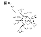
- FIG. 1A and 1B are diagrams for explaining a hierarchical neural network.
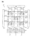
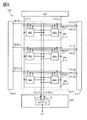
- FIG. 2 is a circuit diagram showing a configuration example of a semiconductor device.
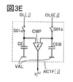
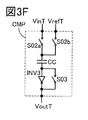
- 3A, 3B, 3C, 3D, 3E, and 3F are circuit diagrams showing configuration examples of circuits included in the semiconductor device.
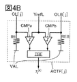
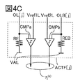
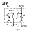
- 4A, 4B, 4C, 4D, 4E, and 4F are circuit diagrams showing configuration examples of circuits included in the semiconductor device.
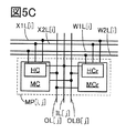
- 5A, 5B, 5C, 5D, 5E, and 5F are circuit diagrams showing configuration examples of circuits included in the semiconductor device.
- FIG. 6 is a circuit diagram showing a configuration example of a semiconductor device.
- FIG. 7 is a circuit diagram showing a configuration example of a semiconductor device.
- FIG. 8 is a circuit diagram showing a configuration example of a semiconductor device.
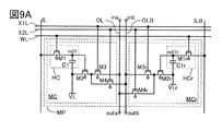
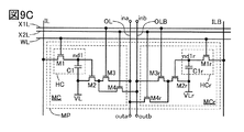
- 9A, 9B, and 9C are circuit diagrams each illustrating a structural example of a circuit included in the semiconductor device.
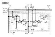
- 10A and 10B are circuit diagrams each illustrating a structural example of a circuit included in the semiconductor device.
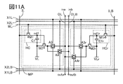
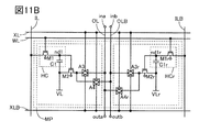
- 11A and 11B are circuit diagrams each illustrating a structural example of a circuit included in the semiconductor device.
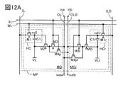
- 12A and 12B are circuit diagrams each illustrating a configuration example of a circuit included in the semiconductor device.
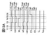
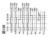
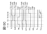
- 13A, 13B, and 13C are timing charts showing an operation example of a circuit included in the semiconductor device.
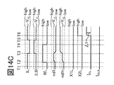
- 14A, 14B, and 14C are timing charts showing operation examples of circuits included in the semiconductor device.
- 15A, 15B, and 15C are timing charts showing an operation example of a circuit included in the semiconductor device.
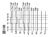
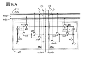
- 16A and 16B are circuit diagrams each illustrating a structural example of a circuit included in a semiconductor device.
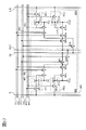
- FIG. 17 is a circuit diagram illustrating a configuration example of a circuit included in a semiconductor device.
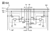
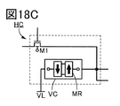
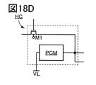
- 18A, 18B, 18C, and 18D are circuit diagrams illustrating configuration examples of circuits included in a semiconductor device.
- FIG. 19 is a circuit diagram illustrating a configuration example of a circuit included in a semiconductor device.
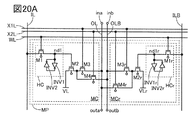
- 20A and 20B are circuit diagrams each illustrating a structural example of a circuit included in a semiconductor device.
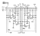
- 21A and 21B are circuit diagrams each illustrating a configuration example of a circuit included in the semiconductor device.
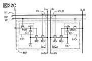
- 22A, 22B, and 22C are circuit diagrams each illustrating a configuration example of a circuit included in the semiconductor device.
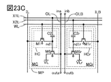
- 23A, 23B, and 23C are circuit diagrams each illustrating a configuration example of a circuit included in a semiconductor device.
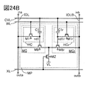
- 24A and 24B are circuit diagrams each illustrating a configuration example of a circuit included in the semiconductor device.
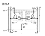
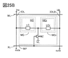
- 25A and 25B are circuit diagrams each illustrating a structural example of a circuit included in the semiconductor device.
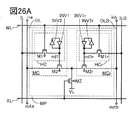
- 26A and 26B are circuit diagrams each illustrating a configuration example of a circuit included in the semiconductor device.
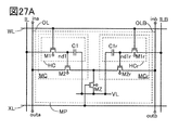
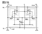
- 27A and 27B are circuit diagrams each illustrating a structural example of a circuit included in a semiconductor device.
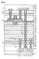
- FIG. 28 is a cross-sectional view showing a structural example of a semiconductor device.
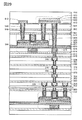
- 29 is a cross-sectional view showing a structural example of a semiconductor device.
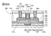
- 30A, 30B, and 30C are cross-sectional views illustrating structural examples of transistors.
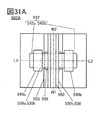
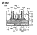
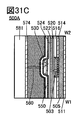
- 31A, 31B, and 31C are a top view and a cross-sectional view illustrating a structural example of a transistor.
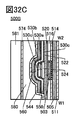
- 32A, 32B, and 32C are a top view and a cross-sectional view illustrating a structural example of a transistor.
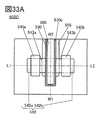
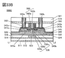
- 33A, 33B, and 33C are a top view and a cross-sectional view illustrating a structural example of a transistor.
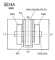
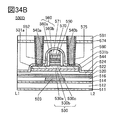
- 34A, 34B, and 34C are a top view and a cross-sectional view illustrating a structural example of a transistor.
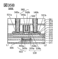
- 35A, 35B, and 35C are a top view and a cross-sectional view illustrating a structural example of a transistor.
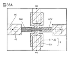
- 36A and 36B are a top view and a perspective view illustrating a structural example of a transistor.
- 37A and 37B are cross-sectional views illustrating a structural example of a transistor.
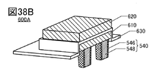
- 38A, 38B, and 38C are a top view and a perspective view showing a structural example of a capacitor.
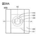
- 39A, 39B, and 39C are a top view and a perspective view showing a structural example of a capacitor.
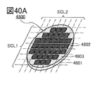
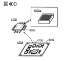
- 40A, 40B, 40C, and 40D are perspective views showing an example of a semiconductor wafer and electronic components.
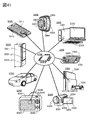
- FIG. 41 is a perspective view showing an example of an electronic device.
- 42A is a front view showing an example of an electronic device
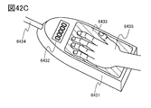
- FIGS. 42B and 42C are perspective views showing an example of an electronic device.
- the synaptic connection strength can be changed by giving existing information to the neural network.
- the process of giving existing information to the neural network and determining the coupling strength may be called “learning”.
- new information can be output based on the bond strength.
- the process of outputting new information based on the given information and the connection strength may be called “inference” or “cognition”.
- a neural network having a multilayer structure may be referred to as a “deep neural network” (DNN), and machine learning using a deep neural network may be referred to as “deep learning”.
- DNN deep neural network
- a metal oxide is a metal oxide in a broad sense. Metal oxides are classified into oxide insulators, oxide conductors (including transparent oxide conductors), oxide semiconductors (Oxide Semiconductor or simply OS), and the like. For example, when a metal oxide is used for the active layer of a transistor, the metal oxide may be referred to as an oxide semiconductor. That is, when a metal oxide can form a channel formation region of a transistor having at least one of an amplification function, a rectification function, and a switching function, the metal oxide is referred to as a metal oxide semiconductor (metal oxide semiconductor). You can When the term “OS FET” or “OS transistor” is used, it can be referred to as a transistor including a metal oxide or an oxide semiconductor.
- metal oxides having nitrogen may be collectively referred to as metal oxides. Further, the metal oxide containing nitrogen may be referred to as a metal oxynitride.
- the contents described in one embodiment are different from the contents described in the embodiment (may be a part of the contents) and one or more different embodiments. It is possible to apply, combine, replace, or the like with respect to at least one of the contents described in the form (or a part of the contents).
- the size, the layer thickness, or the region is exaggerated for clarity in some cases. Therefore, it is not necessarily limited to that scale.
- the drawings schematically show ideal examples and are not limited to the shapes or values shown in the drawings. For example, it may include a signal, voltage, or current variation due to noise, or a signal, voltage, or current variation due to a timing shift.
- the hierarchical neural network has, for example, one input layer, one or more intermediate layers (hidden layers), and one output layer, and is configured by a total of three or more layers.
- the hierarchical neural network 100 shown in FIG. 1A shows an example thereof, and the neural network 100 has first to R-th layers (R in this case can be an integer of 4 or more). ing.
- R in this case can be an integer of 4 or more.
- the first layer corresponds to the input layer
- the R layer corresponds to the output layer
- the other layers correspond to the intermediate layer.
- FIG. 1A illustrates the (k-1) th layer and the kth layer (k is an integer of 3 or more and R-1 or less) as intermediate layers, and other intermediate layers. Are not shown.
- Each layer of the neural network 100 has one or more neurons.
- the first layer includes neurons N 1 (1) to N p (1) (where p is an integer of 1 or more), and the (k ⁇ 1) th layer includes neurons N 1 (1).
- (K ⁇ 1) to neurons N m (k ⁇ 1) (where m is an integer of 1 or more)
- the k-th layer includes neurons N 1 (k) to neurons N n (k) (
- n is an integer of 1 or more.
- the R-th layer has neurons N 1 (R) to neurons N q (R) (q is an integer of 1 or more).
- a k-th layer neuron N j (k) (where j is an integer of 1 or more and n or less) is illustrated, and the other neurons are not illustrated.
- Figure 1B is a neuron N j of the k-th layer (k), shows the signal which is input to the neuron N j (k), a signal output from the neuron N j (k), the.
- the output signals z 1 (k ⁇ 1) to z m (k ⁇ ) of the neurons N 1 (k ⁇ 1) to N m (k ⁇ 1) in the (k ⁇ 1) -th layer are respectively output. 1) is output to the neuron N j (k) . Then, the neuron N j (k) is, z 1 (k-1) to z m (k-1) to generate a z j (k) in response to, the z j (k) is an output signal (k + 1 ) Output to each neuron of the layer (not shown).
- the degree of signal transmission of a signal input from a neuron in the previous layer to a neuron in the next layer is determined by the coupling strength of synapses connecting these neurons (hereinafter referred to as a weighting coefficient).
- the signal output from the neuron in the previous layer is multiplied by the corresponding weight coefficient and input to the neuron in the next layer.
- the synaptic weighting factor between the neuron N i (k ⁇ 1) of the (k ⁇ 1) th layer and the neuron N j (k) of the kth layer is w i (k ⁇ 1) j (k)
- the signal input to the k-th layer neuron N j (k) can be expressed by equation (1.1).
- the neuron N j (k) produces an output signal z j (k) according to u j (k) .
- Neuron N j output signal z j from (k) (k) defined by the following equation.
- the function f (u j (k) ) is an activation function in a hierarchical neural network, and a step function, a linear ramp function, a sigmoid function, or the like can be used.
- the activation function may be the same or different in all neurons.
- the activation function of the neuron may be the same or different in each layer.
- the signals output by the neurons of each layer may be analog values or digital values.
- the digital value may be binary or ternary, for example.
- a linear ramp function or a sigmoid function may be used as the activation function.
- binary digital values for example, a step function with an output of -1 or 1, or 0 or 1 may be used.
- the signal output from the neuron of each layer may have three or more values.
- the activation function has three values, for example, a step function whose output is -1, 0, or 1, or 0, 1, or 2 A step function or the like may be used.
- an input signal is input to the first layer (input layer), so that the layers from the first layer (input layer) to the last layer (output layer) are sequentially input from the previous layer.
- an operation of generating an output signal using equations (1.1) to (1.3) and outputting the output signal to the next layer is performed.
- the signal output from the last layer (output layer) corresponds to the result calculated by the neural network 100.
- the weighting coefficient of the synapse circuit of the neural network 100 is binary (a combination of “ ⁇ 1” and “+1” or a combination of “0” and “+1”), or It has three values (combination of "-1", “0", "1”, etc.), and the activation function of the neuron is binary (combination of "-1", "+1", or "0", "+1”). , Etc.) or a ternary value (combination of “ ⁇ 1”, “0”, “1”, etc.).
- the weight coefficient and the value of the signal input from the neuron of the previous layer to the neuron of the next layer (which may be referred to as an operation value), one of them is referred to as the first data.
- the second data is referred to as the second data.
- the arithmetic circuit 110 illustrated in FIG. 2 is, for example, a semiconductor device including an array unit ALP, a circuit ILD, a circuit WLD, a circuit XLD, and a circuit AFP.
- the arithmetic circuit 110 outputs the signals z 1 (k-1) to z m (k-1) input to the neurons N 1 (k) to N n (k) of the kth layer in FIGS. 1A and 1B. It is a circuit that processes and generates signals z 1 (k) to z n (k) output from the neurons N 1 (k) to N n (k) , respectively.
- the entire arithmetic circuit 110 or a part thereof may be used for purposes other than the neural network and AI.
- the whole or a part of the arithmetic circuit 110 may be used to perform the process. . That is, not only the calculation for AI but also the calculation circuit 110 may be entirely or partially used for general calculation.
- the circuit ILD is electrically connected to the wirings IL [1] to IL [n] and the wirings ILB [1] to ILB [n], for example.
- the circuit WLD is electrically connected to the wirings WLS [1] to WLS [m], for example.
- the circuit XLD is electrically connected to the wirings XLS [1] to XLS [m], for example.
- the circuit AFP is electrically connected to the wirings OL [1] to OL [n] and the wirings OLB [1] to OLB [n], for example.
- the array unit ALP has, for example, m ⁇ n circuits MP.
- the circuits MP are, for example, arranged in a matrix of m rows and n columns in the array unit ALP. Note that, in FIG. 2, the circuit MP [i, where i is an integer of 1 or more and m or less, and j is an integer of 1 or more and n or less] in row i and column j j]. However, in FIG. 2, only the circuit MP [1,1], the circuit MP [m, 1], the circuit MP [i, j], the circuit MP [1, n], and the circuit MP [m, n] are illustrated. The other circuits MPC are not shown.
- the circuit MP [i, j] includes the wiring IL [j], the wiring ILB [j], the wiring WLS [i], the wiring XLS [i], the wiring OL [j], and the wiring OLB [. j] and are electrically connected to.
- the circuit MP [i, j] may be referred to as a weighting coefficient (one of the first data and the second data ) between the neuron N i (k ⁇ 1) and the neuron N j (k) .
- the circuit MP [i, j] has information (eg, potential, resistance value, current) corresponding to the first data (weighting coefficient) input from the wiring IL [j] and the wiring ILB [j]. Value etc.) is retained.
- the circuit MP [i, j] may be referred to as the signal z i (k ⁇ 1) (the other of the first data and the second data ) output from the neuron N i (k ⁇ 1) .
- the circuit MP [i, j] the second data z i (k ⁇ 1) is input from the wiring XLS [i], and thus the product of the first data and the second data is obtained.
- the corresponding information for example, current, voltage, etc.
- information for example, current, voltage, etc.
- Output is supplied to the wiring OL [j] and the wiring OLB [j].
- Only one of the wiring IL [j] and the wiring ILB [j] may be arranged. Note that the example in which the wiring OL [j] and the wiring OLB [j] are provided is described; however, one embodiment of the present invention is not limited to this. Only one of the wiring OL [j] and the wiring OLB [j] may be arranged.
- the circuit ILD includes the circuits MP [1, 1] to MP [m, through the wirings IL [1] to IL [n] and the wirings ILB [1] to ILB [n]. n] for each of the first data w 1 (k ⁇ 1) 1 (k) to w m (k ⁇ 1) n (k) that are weighting factors (for example, potential, resistance value, It has the function of inputting the current value).
- the circuit ILD has information (for example, potential, resistance ) corresponding to the first data w i (k ⁇ 1) j (k) , which is a weighting coefficient, for the circuit MP [i, j]. Value, current value, or the like) is supplied through the wiring IL [j] and the wiring ILB [j].
- the circuit WLD has, for example, a function of selecting a circuit MP to which information (for example, potential, resistance value, current value, etc.) according to the first data input from the circuit ILD is written. For example, when information (for example, a potential, a resistance value, a current value, or the like) is written to the circuits MP [i, 1] to MP [i, n] located in the i-th row of the array portion ALP, the circuit WLD is , For example, a signal for turning on or off a writing switching element included in the circuits MP [i, 1] to MP [i, n] is supplied to the wiring WLS [i] and other than the i-th row The potential for turning off the writing switching element included in the circuit MP may be supplied to the wiring WLS. Note that the example in which the wiring WLS [i] is provided is described; however, one embodiment of the present invention is not limited to this. For example, the wiring WLS [i] may be arranged as a plurality of wiring
- the circuit XLD includes a neuron N 1 (k ⁇ 1 ) for each of the circuits MP [1,1] to MP [m, n] via the wirings XLS [1] to wiring XLS [m]. ) Through neuron N m (k), the second data z 1 (k ⁇ 1) through z m (k ⁇ 1) corresponding to the calculated value are supplied. Specifically, the circuit XLD outputs the second data z i (k ⁇ 1) output from the neuron N i (k ⁇ 1) to the circuits MP [i, 1] to MP [i, n]. Information (for example, potential, current value, etc.) corresponding to is supplied by the wiring XLS [i]. Note that the example in which the wiring XLS [i] is provided is shown; however, one embodiment of the present invention is not limited to this. For example, the wiring XLS [i] may be arranged as a plurality of wirings.
- the circuit AFP includes the circuits ACTF [1] to ACTF [n], for example.
- the circuit ACTF [j] is electrically connected to the wiring OL [j] and the wiring OLB [j], for example.
- the circuit ACTF [j] for example, generates a signal according to each information (for example, potential, current value, etc.) input from the wiring OL [j] and the wiring OLB [j].
- each piece of information for example, a potential, a current value, or the like
- a signal corresponding to the comparison result is generated.
- each of the circuits ACTF [1] to ACTF [n] functions as a circuit that calculates the activation function of the neural network described above.
- the circuits ACTF [1] to ACTF [n] may each have a function of converting an analog signal into a digital signal.
- the circuits ACTF [1] to ACTF [n] may have a function of amplifying and outputting an analog signal, that is, a function of converting output impedance. Note that the example in which the circuit ACTF is provided is shown; however, one embodiment of the present invention is not limited to this.
- the circuit ACTF may not be arranged.
- FIG. 3A illustrates a circuit that generates a signal z j (k) in accordance with a current input from the wiring OL [j] and the wiring OLB [j].
- FIG. 3A shows an example of an activation function arithmetic circuit that outputs an output signal z j (k) represented by two values.
- the circuit ACTF [j] has a resistance element RE, a resistance element REB, and a comparator CMP.
- the resistance element RE and the resistance element REB have a function of converting current into voltage. Therefore, as long as it is an element or a circuit having a function of converting current into voltage, it is not limited to the resistance element.
- the wiring OL [j] is electrically connected to the first terminal of the resistance element RE and the first input terminal of the comparator CMP, and the wiring OLB [j] is connected to the first terminal of the resistance element REB and the comparator. It is electrically connected to the second input terminal of the CMP.
- the second terminal of the resistance element RE is electrically connected to the wiring VAL
- the second terminal of the resistance element REB is electrically connected to the wiring VAL.
- the second terminal of the resistance element RE and the second terminal of the resistance element REB may be connected to the same wiring. Alternatively, they may be connected to different wirings having the same potential.
- the resistance values of the resistance element RE and the resistance element REB are preferably equal to each other. For example, it is desirable that the difference between the resistance values of the resistance element RE and the resistance element REB be within 10%, and more preferably within 5%. However, one embodiment of the present invention is not limited to this. Depending on the case or the situation, the resistance values of the resistance element RE and the resistance element REB may be different from each other.
- the wiring VAL functions as a wiring that gives a constant voltage, for example.
- VDD which is a high level potential
- VSS which is a low level potential
- ground potential (GND) and the like can be used.
- the constant voltage is appropriately set according to the configuration of the circuit MP.
- the wiring VAL may be supplied with a pulse signal instead of a constant voltage.
- the voltage between the first terminal and the second terminal of the resistance element RE is determined according to the current flowing from the wiring OL [j]. Therefore, the resistance value of the resistance element RE and the voltage corresponding to the current are input to the first input terminal of the comparator CMP.
- the voltage between the first terminal and the second terminal of the resistance element REB is determined according to the current flowing from the wiring OLB [j]. Therefore, the resistance value of the resistance element REB and the voltage corresponding to the current are input to the second input terminal of the comparator CMP.
- the comparator CMP has a function of comparing the voltages input to the first input terminal and the second input terminal and outputting a signal from the output terminal of the comparator CMP according to the comparison result.
- the comparator CMP outputs a high level potential from the output terminal of the comparator CMP when the voltage input to the second input terminal is higher than the voltage input to the first input terminal, and then the second input terminal When the voltage input to the first input terminal is higher than the voltage input to, the low level potential can be output from the output terminal of the comparator CMP.
- the output signal z j (k) output from the circuit ACTF [j] should be binary.
- each of the high level potential and the low level potential output from the output terminal of the comparator CMP can correspond to “+1” and “ ⁇ 1” as the output signal z j (k) .
- the high level potential and the low level potential output from the output terminal of the comparator CMP may correspond to “+1” and “0” as the output signal z j (k) .
- the resistance element RE and the resistance element REB are used, but the element or circuit having a function of converting current into voltage is not limited to the resistance element. Therefore, the resistance element RE and the resistance element REB of the circuit ACTF [j] in FIG. 3A can be replaced with another circuit element.
- the circuit ACTF [j] illustrated in FIG. 3B is a circuit in which the resistance element RE and the resistance element REB included in the circuit ACTF [j] in FIG. 3A are replaced with a capacitance element CE and a capacitance element CEB, respectively. An operation similar to that of the circuit ACTF [j] can be performed.
- the capacitance values of the capacitance element CE and the capacitance element CEB are preferably equal to each other.
- a circuit for initializing the electric charge accumulated in the capacitor CE and the capacitor CEB may be provided.
- a switch may be provided in parallel with the capacitive element CE. That is, the second terminal of the switch is connected to the wiring VAL, and the first terminal of the switch is connected to the first terminal of the capacitive element CE, the wiring OL [j], and the first input terminal of the comparator CMP. May be.
- a circuit ACTF [j] illustrated in FIG. 3C is a circuit in which the resistance element RE and the resistance element REB included in the circuit ACTF [j] of FIG. 3A are replaced with a diode element DE and a diode element DEB, respectively. An operation similar to that of the circuit ACTF [j] can be performed. It is desirable that the orientations of the diode element DE and the diode element DEB (connection points between the anode and the cathode) be appropriately changed depending on the magnitude of the potential of the wiring VAL.
- comparator CMP included in the circuits ACTF [j] of FIGS. 3A to 3C can be replaced with the operational amplifier OP as an example.
- the circuit ACTF [j] illustrated in FIG. 3D is a circuit diagram in which the comparator CMP of the circuit ACTF [j] in FIG. 3A is replaced with the operational amplifier OP.
- the circuit ACTF [j] of FIG. 3B may be provided with the switch S01a and the switch S01b. Accordingly, the circuit ACTF [j] can hold potentials corresponding to currents input from the wiring OL [j] and the wiring OLB [j] to the capacitor CE and the capacitor CEB, respectively.
- the wiring OL [j] is electrically connected to the first terminal of the switch S01a, and the second terminal of the switch S01a is connected to the first terminal of the capacitive element CE.
- the first input terminal of the comparator CMP is electrically connected
- the wiring OLB [j] is electrically connected to the first terminal of the switch S01b
- the second terminal of the switch S01b is connected to the first terminal of the capacitive element CEB.
- the configuration may be such that the second input terminal of the comparator CMP is electrically connected.
- the switch S01a and the switch S01b are turned on. This can be done by turning it on.
- the switches S01a and S01b are turned off to hold the potential input to each of the first input terminal and the second input terminal of the comparator CMP in the capacitor CE and the capacitor CEB. be able to.
- the switches S01a and S01b for example, electrical switches such as analog switches or transistors can be used.
- the switches S01a and S01b for example, mechanical switches may be applied.
- the transistor when a transistor is used for the switch S01a and the switch S01b, the transistor can be an OS transistor or a transistor including silicon in a channel formation region (hereinafter referred to as a Si transistor).
- the voltage values of the capacitor CE and the capacitor CEB can be controlled by controlling the period in which the switch S01a and the switch S01b are kept on. For example, when the value of the current flowing through the capacitive element CE and the capacitive element CEB is large, the voltage of the capacitive element CE and the capacitive element CEB can be reduced by shortening the period in which the switch S01a and the switch S01b are kept on. It is possible to prevent the value from becoming too large.
- the comparator CMP included in the circuits ACTF [j] of FIGS. 3A to 3C and 3E can be, for example, a chopper type comparator.
- the comparator CMP shown in FIG. 3F shows a chopper type comparator, and the comparator CMP includes a switch S02a, a switch S02b, a switch S03, a capacitive element CC, and an inverter circuit INV3.
- the switch S02a, the switch S02b, and the switch S03 can be mechanical switches, transistors such as OS transistors, Si transistors, and the like, like the switches S01a and S01b described above.
- the first terminal of the switch S02a is electrically connected to the terminal VinT
- the first terminal of the switch S02b is electrically connected to the terminal VrefT
- the second terminal of the switch S02a is the second terminal of the switch S02b. It is electrically connected to the first terminal of the capacitive element CC.
- the second terminal of the capacitive element CC is electrically connected to the input terminal of the inverter circuit INV3 and the first terminal of the switch S03.
- the terminal VoutT is electrically connected to the output terminal of the inverter circuit INV3 and the second terminal of the switch S03.
- the terminal VinT functions as a terminal for inputting an input potential to the comparator CMP
- the terminal VrefT functions as a terminal for inputting a reference potential to the comparator CMP
- the terminal VoutT is an output potential from the comparator CMP. Functions as a terminal for outputting.
- the terminal VinT corresponds to one of the first terminal and the second terminal of the comparator CMP of FIGS. 3A to 3C and 3E
- the terminal VrefT is the first terminal of the comparator CMP of FIGS. 3A to 3C and 3E. It can correspond to the other of the one terminal or the second terminal.
- ACTF [j] is a calculation circuit of the activation function for outputting an output signal z j (k) expressed by binary
- circuit ACTF [j] is the output signal z j ( k) may be output in three or more values or as an analog value.
- 4A to 4F are circuits that generate a signal z j (k) in accordance with a current input from the wiring OL [j] and the wiring OLB [j], and are output signals z j represented by three values.
- An example of an activation function arithmetic circuit that outputs (k) is shown.
- the circuit ACTF [j] illustrated in FIG. 4A includes a resistance element RE, a resistance element REB, a comparator CMPa, and a comparator CMPb.
- the wiring OL [j] is electrically connected to the first terminal of the resistance element RE and the first input terminal of the comparator CMPa
- the wiring OLB [j] is connected to the first terminal of the resistance element REB and the comparator. It is electrically connected to the first input terminal of CMPb.
- the second input terminal of the comparator CMPa and the second input terminal of the comparator CMPb are electrically connected to the wiring VrefL.
- the second terminal of the resistance element RE is electrically connected to the wiring VAL
- the second terminal of the resistance element REB is electrically connected to the wiring VAL.
- the wiring VrefL functions as a wiring that supplies a constant voltage Vref, and Vref is preferably, for example, GND or more and VDD or less. Further, depending on the situation, V ref may be a potential lower than GND or a potential higher than VDD. V ref is treated as a reference potential (comparison potential) in the comparator CMPa and the comparator CMPb.
- the voltage between the first terminal and the second terminal of the resistance element RE is determined according to the current flowing from the wiring OL [j]. Therefore, the resistance value of the resistance element RE and the voltage corresponding to the current are input to the first input terminal of the comparator CMPa.
- the voltage between the first terminal and the second terminal of the resistance element REB is determined according to the current flowing from the wiring OLB [j]. Therefore, the resistance value of the resistance element REB and the voltage corresponding to the current are input to the first input terminal of the comparator CMPb.
- the comparator CMPa compares the voltages input to the first input terminal and the second input terminal, and outputs a signal from the output terminal of the comparator CMPa according to the comparison result. For example, the comparator CMPa outputs a high level potential from the output terminal of the comparator CMPa when the voltage (V ref ) input to the second input terminal is higher than the voltage input to the first input terminal, When the voltage input to the first input terminal is higher than the voltage (V ref ) input to the second input terminal, the low-level potential can be output from the output terminal of the comparator CMPa.
- the comparator CMPb compares the voltages input to the first input terminal and the second input terminal, and outputs a signal from the output terminal of the comparator CMPb according to the comparison result. To do. For example, the comparator CMPb outputs a high level potential from the output terminal of the comparator CMPb when the voltage (V ref ) input to the second input terminal is higher than the voltage input to the first input terminal, When the voltage input to the first input terminal is higher than the voltage (V ref ) input to the second input terminal, the low-level potential can be output from the output terminal of the comparator CMPb.
- a ternary output signal z j (k) can be represented according to the potentials output from the output terminals of the comparator CMPa and the comparator CMPb. For example, when a high level potential is output from the output terminal of the comparator CMPa and a low level potential is output from the output terminal of the comparator CMPb, the output signal z j (k) is set to “+1” and the output of the comparator CMPa is output.
- the output signal z j (k) is “ ⁇ 1”, and the low-level potential is output from the output terminal of the comparator CMPa.
- the output signal z j (k) can be “+0”.
- the circuit ACTF [j] is not limited to the circuit configuration illustrated in FIG. 4A and can be changed depending on the situation.
- the conversion circuit TRF may be provided in the circuit ACTF [j].
- the circuit ACTF [j] in FIG. 4B is a configuration example in which the conversion circuit TRF is provided in the circuit ACTF [j] in FIG. 4A, and the output terminals of the comparators CMPa and CMPb are electrically connected to the input terminals of the conversion circuit TRF. Connected to each other.
- a digital-analog conversion circuit in this case, the signal z j (k) becomes an analog value
- the wiring VrefL electrically connected to the respective second input terminals of the comparator CMPa and the comparator CMPb may be replaced with separate wirings Vref1L and Vref2L.
- the second terminal of the comparator CMPa included in the circuit ACTF [j] of FIG. 4A is electrically connected to the wiring Vref1L instead of the wiring VrefL, and the second terminal of the comparator CMPb is connected.
- the terminal is electrically connected to the wiring Vref2L instead of the wiring VrefL.
- an amplifier circuit, an impedance conversion circuit, or the like may be used as a configuration different from the circuit ACTF [j] of FIGS. 4A to 4C.
- the circuit ACTF [j] illustrated in FIG. 4D can be applied to the circuit AFP of the arithmetic circuit 110 in FIG.
- the circuit ACTF [j] in FIG. 4D has a resistance element RE, a resistance element REB, an operational amplifier OPa, and an operational amplifier OPb, and functions as an amplifier circuit.
- the wiring OL [j] is electrically connected to the first terminal of the resistance element RE and the non-inverting input terminal of the operational amplifier OPa, and the wiring OLB [j] is connected to the first terminal of the resistance element REB and the operational amplifier OPb. It is electrically connected to the non-inverting input terminal.
- the inverting input terminal of the operational amplifier OPa is electrically connected to the output terminal of the operational amplifier OPa, and the inverting input terminal of the operational amplifier OPb is electrically connected to the output terminal of the operational amplifier OPb.
- the second terminal of the resistance element RE is electrically connected to the wiring VAL, and the second terminal of the resistance element REB is electrically connected to the wiring VAL.
- the operational amplifiers OPa and OPb included in the circuit ACTF [j] of FIG. 4D have a voltage follower connection configuration.
- the potential output from the output terminal of the operational amplifier OPa becomes substantially equal to the potential input to the non-inverting input terminal of the operational amplifier OPa
- the potential output from the output terminal of the operational amplifier OPb is the non-inverting input terminal of the operational amplifier OPb. It is almost equal to the potential input to the terminal.
- the output signal z j (k) is output from the circuit ACTF [j] as two analog values.
- the output terminal of the operational amplifier OPa and the output terminal of the operational amplifier OPb may be connected to the input terminals of the comparator CMP, respectively. Then, the output from the comparator CMP may be used as the output signal z j (k) .
- an integration circuit, a current-voltage conversion circuit, or the like may be used as a configuration different from the circuit ACTF [j] of FIGS. 4A to 4D.
- an operational amplifier may be used to configure the integrating circuit and the current-voltage converting circuit.
- the circuit ACTF [j] illustrated in FIG. 4E can be applied to the circuit AFP of the arithmetic circuit 110 in FIG.
- the circuit ACTF [j] in FIG. 4E includes an operational amplifier OPa, an operational amplifier OPb, a load element LEa, and a load element LEb.
- the wiring OL [j] is electrically connected to the first input terminal (for example, the inverting input terminal) of the operational amplifier OPa and the first terminal of the load element LEa, and the wiring OLB [j] is the first input terminal of the operational amplifier OPb.
- One input terminal (for example, an inverting input terminal) is electrically connected to the first terminal of the load element LEb.
- the second input terminal (for example, non-inverting input terminal) of the operational amplifier OPa is electrically connected to the wiring Vref1L
- the second input terminal (for example, non-inverting input terminal) of the operational amplifier OPb is electrically connected to the wiring Vref2L. It is connected to the.
- the second terminal of the load element LEa is electrically connected to the output terminal of the operational amplifier OPa
- the second terminal of the load element LEa is electrically connected to the output terminal of the operational amplifier OPb.
- the wiring Vref1L and the wiring Vref2L here function as wirings that supply a voltage equal to or different from each other. Therefore, the wiring Vref1L and the wiring Vref2L can be combined into one wiring.
- the load element LEa and the load element LEb can be, for example, a resistance element or a capacitance element.
- the operational amplifier OPa and the load element LEa, and the operational amplifier OPb and the load element LEb respectively function as an integrating circuit. That is, electric charge is stored in each of the capacitance elements (load elements LEa and LEb) depending on the amount of current flowing through the wiring OL [j] or the wiring OLB [j].
- the current flowing from the wiring OL [j] and the wiring OLB [j] is converted into a voltage by the integrating circuit, and the integrated current amount is output as a signal z j (k) .
- the output terminal of the operational amplifier OPa and the output terminal of the operational amplifier OPb may be connected to the input terminals of the comparator CMP, respectively. Then, the output from the comparator CMP may be used as the output signal z j (k) .
- a circuit for initializing the charge accumulated in the capacitive elements of the load element LEa and the load element LEb may be provided.
- a switch may be provided in parallel with the load element LEa (capacitive element).
- the second terminal of the switch is connected to the output terminal of the operational amplifier OPa, and the first terminal of the switch is connected to the wiring OL [j] and the first input terminal (for example, inverting input terminal) of the operational amplifier OPa. May be.
- the load element LEa and the load element LEb should be other than the capacitive element. Can use a resistance element.
- the circuit ACTF [j] shown in FIG. 4F can be applied to the circuit AFP of the arithmetic circuit 110 of FIG.
- the circuit ACTF [j] in FIG. 4F includes a resistance element RE, a resistance element REB, an analog-digital conversion circuit ADCa, and an analog-digital conversion circuit ADCb.
- the wiring OL [j] is electrically connected to the input terminal of the analog-digital conversion circuit ADCa and the first terminal of the resistance element RE, and the wiring OLB [j] is the input terminal of the analog-digital conversion circuit ADCb. It is electrically connected to the first terminal of the resistance element REB.
- the second terminal of the resistance element RE is electrically connected to the wiring VAL, and the second terminal of the resistance element REB is electrically connected to the wiring VAL.
- the potentials of the first terminals of the resistance element RE and the resistance element REB are determined according to the currents flowing from the wiring OL [j] and the wiring OLB [j]. Then, the circuit ACTF [j] converts the potential, which is an analog value, into a binary value or a digital value of three values or more (for example, 256 values) by the analog-digital conversion circuits ADCa and ADCb, and outputs the signal z j. It has a function of outputting as (k) .
- the resistance element RE and the resistance element REB illustrated in FIGS. 4A to 4F can be replaced with the capacitance element CE, the capacitance element CEB, or the diode element DE and the diode element DEB, as in FIGS. 3B and 3C.
- the resistance element RE and the resistance element REB illustrated in FIGS. 4A to 4F are replaced with the capacitance element CE and the capacitance element CEB, by further providing the switch S01a and the switch S01b similarly to FIG. 3E, the wiring OL [j ], And the potential input from the wiring OLB [j] can be held.
- the arithmetic circuit 110 in FIG. 2 can change the number of wirings electrically connected to the circuit MP [i, j] according to the circuit configuration of the circuit MP [i, j].
- the wiring WLS [i] electrically connected to the circuit MP [i, j] can be one or a plurality of wirings.
- the wiring XLS [i] electrically connected to the circuit MP [i, j] can be one or a plurality of wirings.
- FIG. 5A shows a configuration example of a circuit MP [i, j] applicable to the arithmetic circuit 110, and the circuit MP [i, j] has, for example, a circuit MC and a circuit MCr.
- the circuit MC and the circuit MCr are circuits for calculating the product of the weight coefficient and the input signal (calculated value) of the neuron in the circuit MP.
- the circuit MC can have a structure similar to that of the circuit MCr or a structure different from that of the circuit MCr. Therefore, in order to distinguish the circuit MCr from the circuit MC, “r” is added to the code.
- reference numerals of circuit elements, which will be described later, included in the circuit MCr are also denoted by “r”.
- the circuit MC has, for example, a holding unit HC, and the circuit MCr has a holding unit HCr.
- the holding unit HC and the holding unit HCr each have a function of holding information (for example, potential, resistance value, current value, etc.).
- the first data w i (k ⁇ 1) j (k) set in the circuit MP [i, j] is information (for example, potential, resistance value) held in each of the holding unit HC and the holding unit HCr. , Current value, etc.). Therefore, each of the holding unit HC and the holding unit HCr supplies the wiring IL [that supplies information (for example, potential, resistance value, current value, etc.) according to the first data w i (k ⁇ 1) j (k) . j] and the wiring ILB [j].
- the wiring WL [i] illustrated in FIG. 5A corresponds to the wiring WLS [i] in FIG.
- the wiring WL [i] is electrically connected to each of the holding portion HC and the holding portion HCr.
- Information for example, potential, resistance value, current value, etc.
- corresponding to the first data w i (k ⁇ 1) j (k) is stored in each of the holding unit HC and the holding unit HCr included in the circuit MP [i, j].
- Is written by supplying a predetermined potential to the wiring WL [i], the wiring IL [j] and the holding portion HC are brought into conduction and the wiring ILB [j] and the holding portion HCr are brought into conduction. To do.
- the holding portion HC and the holding portion HCr are respectively supplied.
- the potential or the like can be input to.
- a predetermined potential is supplied to the wiring WL [i] so that the wiring IL [j] and the holding portion HC are brought out of electrical conduction and the wiring ILB [j] and the holding portion HCr are brought out of electrical conduction.
- each of the holding unit HC and the holding unit HCr holds a potential or the like corresponding to the first data w i (k ⁇ 1) j (k) .
- the holding unit HC holds the high-level potential and the holding unit HCr holds the low-level potential.
- the holding unit HC holds the low level potential and the holding unit HCr holds the high level potential.
- the holding unit HC holds the low-level potential and the holding unit HCr holds the low-level potential.
- the first data w i (k ⁇ 1) j (k) is an analog value, specifically, a “negative analog value”, “0”, or a “positive analog value”.
- the holding unit HC holds a high level analog potential and the holding unit HCr holds a low level potential.
- the holding unit HC holds the low-level potential and the holding unit HCr holds the high-level analog potential. Hold.
- the analog value may be a multi-bit (multi-value) digital value. That is, as an example, when the first data w i (k ⁇ 1) j (k) is “1”, “2”, “3”, as an example, the holding unit HC has “1”, “ A high level potential having a potential corresponding to 2 "and” 3 "is held, and a low level potential is held in the holding portion HCr.
- the holding unit HC holds the low level potential.
- the holding unit HCr holds high-level potentials corresponding to the absolute values "1", “2”, and “-3" of "1", "2", and "3”. Then, when the first data w i (k ⁇ 1) j (k) is “0”, as an example, the holding unit HC holds the low-level potential and the holding unit HCr holds the low-level potential.
- the circuit MC uses the wiring OL [j] or the wiring OLB [j] to supply a current, a voltage, or the like according to the information (eg, potential, resistance value, current value, etc.) held in the holding unit HC.
- the circuit MCr has a function of outputting to one side, and the circuit MCr supplies the wiring OL [j] or the wiring OLB with a current, a voltage, or the like according to the information (eg, potential, resistance value, current value, or the like) held in the holding portion HCr. It has a function of outputting to the other of [j].
- the circuit MC when the holding unit HC holds the high level potential, the circuit MC outputs a current having the first current value, and when the holding unit HC holds the low level potential, the circuit MC outputs the second current. A current with a value shall be output.
- the circuit MCr when the holding portion HCr holds the high level potential, the circuit MCr outputs a current having the first current value, and when the holding portion HCr holds the low level potential, the circuit MCr holds the second level. A current having a current value shall be output.
- the magnitudes of the first current value and the second current value are determined by the configurations of the circuit MC, the circuit MCr, the holding unit HC, the holding unit HCr, and the first data w i (k ⁇ 1) j (k).
- the first current value may be larger or smaller than the second current value. Further, one of the first current value and the second current value may be zero current, that is, the current value may be zero. Alternatively, a current having a first current value and a current having a second current value may have different directions of current flow. Particularly, for example, when the first data w i (k ⁇ 1) j (k) takes one of three values “ ⁇ 1”, “0”, and “1”, the first current value or the second current value It is preferable to configure the circuit MC and the circuit MCr so that one of them becomes 0. When the first data w i (k ⁇ 1) j (k) has an analog value, for example, “negative analog value”, “0”, or “positive analog value”, the first current The value or the second current value can also be an analog value, for example.
- a current, a voltage, or the like in accordance with information (eg, a potential, a resistance value, a current value, or the like) held in the holding portion HC and the holding portion HCr may be a positive current, a voltage, or the like. It may be a negative current or voltage, or both positive and negative may be mixed. That is, for example, a current, a voltage, or the like corresponding to the information (for example, the potential, the resistance value, the current value, or the like) held in the holding unit HC is supplied to one of the wiring OL [j] and the wiring OLB [j].
- the circuit MCr has a function of outputting, and the wiring MC [j] or the wiring OLB [j] outputs a current, a voltage, or the like in accordance with information (eg, a potential, a resistance value, a current value, or the like) held in the holding unit HCr.
- information eg, a potential, a resistance value, a current value, or the like
- the wiring X1L [i] and the wiring X2L [i] illustrated in FIG. 5A correspond to the wiring XLS [i] in FIG.
- the second data z i (k ⁇ 1) input to the circuit MP [i, j] is determined by, for example, the potentials and currents of the wiring X1L [i] and the wiring X2L [i], respectively.
- each potential corresponding to the second data z i (k ⁇ 1) is input to the circuit MC and the circuit MCr through the wiring X1L [i] and the wiring X2L [i].
- the circuit MC is electrically connected to the wiring OL [j] and the wiring OLB [j]
- the circuit MCr is electrically connected to the wiring OL [j] and the wiring OLB [j].
- the circuit MC and the circuit MCr are, for example, the first data w i (on the wiring OL [j] and the wiring OLB [j] in accordance with the potentials input to the wiring X1L [i] and the wiring X2L [i].
- k ⁇ 1) j (k) and the second data z i (k ⁇ 1) are output as a current, a potential, or the like according to the product.
- the output destination of the current from the circuits MC and MCr is determined by the potentials of the wiring X1L [i] and the wiring X2L [i].
- a current output from the circuit MC flows to one of the wiring OL [j] and the wiring OLB [j]
- a current output from the circuit MCr flows to the wiring OL [j] or
- the circuit configuration is such that it flows to the other side of the wiring OLB [j]. That is, the respective currents output from the circuit MC and the circuit MCr flow not in the same wiring but in different wirings. Note that as an example, current may not flow from the circuit MC and the circuit MCr to either the wiring OL [j] or the wiring OLB [j].
- the second data z i (k ⁇ 1) takes one of three values “ ⁇ 1”, “0”, and “1”.
- the circuit MP brings the circuit MC and the wiring OL [j] into a conductive state and connects the circuit MCr and the wiring OLB [j].
- the circuit MP brings the circuit MC and the wiring OLB [j] into a conductive state, and the circuit MCr and the wiring OL [j. ] Is brought into conduction.
- the circuit MC and the wiring OL [j] and the circuit MC and the wiring OLB [j] are brought into a non-conduction state, and the circuit MCr and the wiring OL [j] are disconnected. And the circuit MCr and the wiring OLB [j] are made non-conductive.
- the first data w i (k ⁇ 1) j (k) is “1” and the second data z i (k ⁇ 1) is “1”.
- the current I1 [i, j] having the first current value flows from the circuit MC to the wiring OL [j]
- the magnitude of the second current value is, for example, zero. That is, strictly speaking, no current flows from the circuit MCr to the wiring OLB [j].
- the circuit MCr has a current I2 [i, j] having a first current value flowing to the wiring OLB [j].
- the magnitude of the second current value is, for example, zero. That is, strictly speaking, no current flows from the circuit MC to the wiring OL [j].
- the first line from the circuit MC to the wiring OL [j] is A current I1 [i, j] having two current values flows, and a current I2 [i, j] having a second current value flows from the circuit MCr to the wiring OLB [j].
- the magnitude of the second current value is, for example, zero. That is, strictly speaking, no current flows from the circuit MC to the wiring OL [j], and no current flows from the circuit MCr to the wiring OLB [j].
- the circuit MC When the first data w i (k ⁇ 1) j (k) is “1” and the second data z i (k ⁇ 1) is “ ⁇ 1”, the circuit MC to the wiring OLB [j ], The current I1 [i, j] having the first current value flows, and the circuit MCr supplies the current I2 [i, j] having the second current value to the wiring OL [j]. At this time, the magnitude of the second current value is, for example, zero. That is, strictly speaking, no current flows from the circuit MCr to the wiring OL [j]. When the first data w i (k ⁇ 1) j (k) is “ ⁇ 1” and the second data z i (k ⁇ 1) is “ ⁇ 1”, the circuit MC to the wiring OLB [j].
- the current I1 [i, j] having the second current value flows through the circuit MCr, and the current I2 [i, j] having the first current value flows through the wiring OL [j] from the circuit MCr.
- the magnitude of the second current value is, for example, zero. That is, strictly speaking, no current flows from the circuit MC to the wiring OLB [j].
- the current I1 [i, j] having the second current value flows, and the current I2 [i, j] having the second current value flows from the circuit MCr to the wiring OL [j].
- the magnitude of the second current value is, for example, zero. That is, strictly speaking, no current flows from the circuit MC to the wiring OLB [j], and no current flows from the circuit MCr to the wiring OL [j].
- the circuit MC or the circuit A current flows through the wiring OL [j] from any of MCr.
- the first data w i (k ⁇ 1) j (k) has a positive value
- a current flows from the circuit MC to the wiring OL [j] and the first data w i (k ⁇ 1) j.
- (k) has a negative value
- a current flows from the circuit MCr to the wiring OL [j].
- the sum of the currents output from the plurality of circuits MC or the circuits MCr connected to the wiring OL [j] flows to the wiring OL [j]. That is, a current having a sum of positive values flows in the wiring OL [j].
- the sum of the currents output from the plurality of circuits MC or the circuits MCr connected to the wiring OLB [j] flows to the wiring OLB [j]. That is, in the wiring OLB [j], a current having a value obtained by adding the negative values flows.
- the total current value flowing through the wiring OL [j] that is, the sum of positive values
- the total current value flowing through the wiring OLB [j] that is, the sum of negative values
- the product-sum calculation process can be performed. For example, when the total current value flowing through the wiring OL [j] is larger than the total current value flowing through the wiring OLB [j], it is determined that the sum of products operation has a positive value. You can When the total current value flowing through the wiring OL [j] is smaller than the total current value flowing through the wiring OLB [j], it can be determined that the product-sum operation has a negative value. . When the total current value flowing through the wiring OL [j] and the total current value flowing through the wiring OLB [j] are approximately the same value, it is determined that the result of the product-sum calculation is zero. You can
- the second data z i (k ⁇ 1) is any two values of “ ⁇ 1”, “0”, and “1”, for example, two values “ ⁇ 1” and “1”.
- the same operation can be performed in the case of binary values of "0” and "1”.
- the first data w i (k ⁇ 1) j (k) is one of two values “ ⁇ 1”, “0”, and “1”, for example, “ ⁇ 1”, “1”. The same operation can be performed in the case of "2” or in the case of "0" or "1".
- the first data w i (k ⁇ 1) j (k) may take an analog value or a multi-bit (multi-value) digital value.
- a “negative analog value” may be taken instead of “ ⁇ 1”
- a “positive analog value” may be taken instead of “1”.
- the magnitude of the current flowing from the circuit MC or the circuit MCr is, for example, an analog value corresponding to the absolute value of the value of the first data w i (k ⁇ 1) j (k) .
- circuit MP [i, j] of FIG. 5A is modified.
- the parts different from the circuit MP [i, j] of FIG. 5A will be mainly described, and the parts common to the circuit MP [i, j] of FIG. 5A will be described. Description may be omitted.
- the circuit MP [i, j] shown in FIG. 5B is a modification of the circuit MP [i, j] shown in FIG. 5A.
- the circuit MP [i, j] in FIG. 5B includes a circuit MC and a circuit MCr, similar to the circuit MP [i, j] in FIG. 5A.
- the circuit MP [i, j] of FIG. 5B is different from the circuit MP [i, j] of FIG. 5A in that the circuit MCr does not include the holding unit HCr.
- the circuit MCr does not include the holding portion HCr, the arithmetic circuit to which the circuit MP [i, j] in FIG. 5B is applied has the wiring ILB [j] for supplying the potential held in the holding portion HCr. You don't have to. In addition, the circuit MCr does not need to be electrically connected to the wiring WL [i].
- the holding unit HC included in the circuit MC is electrically connected to the circuit MCr. That is, the circuit MP [i, j] in FIG. 5B is configured such that the circuit MCr and the circuit MC share the holding unit HC with each other. As an example, an inverted signal of the signal held by the holding unit HC can be supplied from the holding unit HC to the circuit MCr. This allows the circuit MC and the circuit MCr to perform different operations. Alternatively, the circuit MC and the circuit MCr are made to have different internal circuit configurations, and as a result, the magnitude of the current output by the circuit MC and the circuit MCr with respect to the same signal held by the holding unit HC.
- the potential corresponding to the first data w i (k ⁇ 1) j (k) is held in the holding unit HC, and the potential corresponding to the second data z i (k ⁇ 1) is applied to the wiring X1L [i] and By supplying to the wiring X2L [i], the circuit MP [i, j] causes the wiring OL [j] and the wiring OLB [j] to have the first data w i (k ⁇ 1) j (k) and the second data. It is possible to output a current according to the product of the data z i (k-1) .
- the arithmetic circuit 110 to which the circuit MP of FIG. 5B is applied can be changed to the circuit configuration of the arithmetic circuit 120 shown in FIG.
- the arithmetic circuit 120 has a structure in which the wirings ILB [1] to ILB [m] are removed from the arithmetic circuit 110 in FIG.
- the circuit MP [i, j] shown in FIG. 5C is a modification of the circuit MP [i, j] of FIG. 5A, and specifically, the circuit MP [i, j] applicable to the arithmetic circuit 120 of FIG. It is a configuration example of.
- the circuit MP [i, j] in FIG. 5C includes a circuit MC and a circuit MCr, similar to the circuit MP [i, j] in FIG. 5A.
- the circuit MP [i, j] of FIG. 5C and the circuit MP [i, j] of FIG. 5A have different wiring configurations electrically connected.
- the wiring W1L [i] and the wiring W2L [i] illustrated in FIG. 5C correspond to the wiring WLS [i] in FIG.
- the wiring W1L [i] is electrically connected to the holding portion HC, and the wiring W2L [i] is electrically connected to the holding portion HCr.
- the wiring IL [j] is electrically connected to the holding unit HC and the holding unit HCr.
- the holding operation of the potentials in the holding portion HC and the holding portion HCr is performed sequentially, not simultaneously.
- the first data w i (k ⁇ 1) j (k) of the circuit MP [i, j] can be expressed by holding the first potential in the holding unit HC and the second potential in the holding unit HCr.
- a predetermined potential is applied to each of the wiring W1L [i] and the wiring W2L [i] so that the holding portion HC and the wiring IL [j] are brought into a conductive state and the holding portion HCr and the wiring IL [j]. ]
- the first potential can be applied to the holding portion HC by supplying the first potential to the wiring IL [j].
- a predetermined potential is applied to each of the wiring W1L [i] and the wiring W2L [i] to bring the holding portion HC and the wiring IL [j] into a non-conductive state, and the holding portion HCr and the wiring IL [].
- j] is brought into conduction.
- the second potential can be applied to the holding portion HCr. Accordingly, the circuit MP [i, j] can set w i (k ⁇ 1) j (k) as the first data.
- the holding unit HC and the holding unit HCr when holding substantially equal potentials to the holding unit HC and the holding unit HCr (the first data w i (k ⁇ 1) j (k) of the circuit MP [i, j] is the holding unit HC and the holding unit HC, respectively.
- the holding portion HC and the wiring IL [j] When set by holding potentials that are substantially equal to each of the HCr), the holding portion HC and the wiring IL [j] are brought into conduction, and the holding portion HCr and the wiring IL [j] are brought into conduction.
- a predetermined potential may be applied to each of the wiring W1L [i] and the wiring W2L [i] so that the state is achieved, and then the potential is supplied to the wiring IL [j].
- the circuit MP [i, j] in FIG. 5C holds the potential according to the first data w i (k ⁇ 1) j (k) in the holding unit HC and the holding unit HCr, and the second data z i (k).
- the wiring OL [j] and the wiring OLB [j] are provided as in the circuit MP [i, j] in FIG. 5A.
- the circuit MP [i, j] shown in FIG. 5D is a modification of the circuit MP [i, j] shown in FIG. 5A.
- the circuit MP [i, j] in FIG. 5D includes a circuit MC and a circuit MCr, similar to the circuit MP [i, j] in FIG. 5A.
- the circuit MP [i, j] of FIG. 5D and the circuit MP [i, j] of FIG. 5A have different wiring configurations electrically connected.
- the wiring IOL [j] in FIG. 5D functions as a wiring in which the wiring IL [j] and the wiring OL [j] in FIG. 5A are combined, and the wiring IOLB [j] in FIG. 5D is the wiring in FIG. 5A.
- the ILB [j] and the wiring OLB [j] function as one wiring. Therefore, the wiring IOL [j] is electrically connected to the holding portion HC, the circuit MC, and the circuit MCr, and the wiring IOL [j] is connected to the holding portion HCr, the circuit MC, and the circuit MCr. It is electrically connected.
- the wiring WL [i] is set to a predetermined state such that the holding portion HC and the wiring IOL [j] are brought out of conduction and the holding portion HCr and the wiring IOLB [j] are brought out of conduction.
- each of the holding unit HC and the holding unit HCr can hold each potential according to the first data w i (k ⁇ 1) j (k) .
- the potential corresponding to the second data z i (k-1) is wired.
- the first data w i (k -1) It is possible to output a current according to the product of j (k) and the second data z i (k-1) .
- the arithmetic circuit 110 to which the circuit MP of FIG. 5D is applied can be changed to the circuit configuration of the arithmetic circuit 130 shown in FIG. 7.
- the arithmetic circuit 130 in FIG. 2 includes the wirings IL [1] to IL [n] and the wirings OL [1] to OL [n] in the wirings IOL [1] to IOL [n. ],
- the wirings ILB [1] to ILB [n] and the wirings OLB [1] to OLB [n] are combined as wirings IOLB [1] to IOLB [n]. .
- the wirings IOL [1] to IOL [n] and the wirings IOLB [1] to IOLB [n] are electrically connected to the circuit ILD. That is, the wiring IOL [j] and the wiring IOLB [j] have a signal line for transmitting the first data w i (k ⁇ 1) j (k) to the circuit MP [i, j], and the circuit ACTF. And a current line for supplying a current to [j].
- the circuit ILD when transmitting the first data w i (k ⁇ 1) j (k) to the circuit MP [i, j], the circuit ILD includes the circuit ILD and the wiring IOL [j] and the circuit ILD.
- Conduction is established between the wiring IOLB [j] and the circuit ACTF [j] is arranged between the circuit ACTF [j] and the wiring IOL [j] and between the circuit ACTF [i] and the wiring IOLB [j]. Is preferably in a non-conducting state. Then, when supplying current to the circuit ACTF [j], the circuit ILD makes the circuit ILD and the wiring IOL [j] and the circuit ILD and the wiring IOLB [j] non-conductive, It is preferable that the ACTF [j] be electrically conductive between the circuit ACTF [j] and the wiring IOL [j] and between the circuit ACTF [j] and the wiring IOLB [j].
- the circuit MP [i, j] shown in FIG. 5E is a modification of the circuit MP [i, j] shown in FIG. 5A, and specifically, the circuit MP [i, j] applicable to the arithmetic circuit 110 shown in FIG. It is a configuration example of.
- the circuit MP [i, j] in FIG. 5E includes a circuit MC and a circuit MCr, similar to the circuit MP [i, j] in FIG. 5A.
- the circuit MC is not electrically connected to the wiring OLB [j] and the circuit MCr is not electrically connected to the wiring OL [j]. And are different from the circuit MP [i, j] in FIG. 5A.
- the wiring WL [i] shown in FIG. 5E corresponds to the wiring WLS [i] in FIG.
- the wiring WL [i] is electrically connected to the holding portion HC and the holding portion HCr.
- the wiring XL [i] shown in FIG. 5E corresponds to the wiring XLS [i] in FIG.
- the wiring XL [i] is electrically connected to the circuit MC and the circuit MCr.
- the circuit MC is not electrically connected to the wiring OLB [j]
- the circuit MCr is not electrically connected to the wiring OL [j]. That is, in the circuit MP [i, j] in FIG. 5E, unlike the circuits MP [i, j] in FIGS. 5A to 5D, the current output from the circuit MC does not flow in the wiring OLB [j] and the circuit MCr The output current does not flow to the wiring OL [j].
- the circuit MP [i, j] of FIG. 5E is preferably applied to the arithmetic circuit when the second data z i (k ⁇ 1) is a binary value of “0” or “1”.
- the circuit MP brings the circuit MC and the wiring OL [j] into a conductive state and connects the circuit MCr and the wiring OLB [j].
- the circuit MP brings the circuit MC and the wiring OL [j] into a non-conduction state and the circuit MCr and the wiring OLB [j] into a non-conduction state.
- the first data w i (k ⁇ 1) j (k) is “ ⁇ 1”, “0”, “. It is possible to perform an operation in the case where the second data z i (k ⁇ 1) takes one of the three values “1” and the two values of “0” and “1”.
- the first data w i (k ⁇ 1) j (k) is one of binary values of “ ⁇ 1”, “0”, and “1”.
- the operation can be performed in the case of binary values of "-1" and "1” or in the case of binary values of "0" and "1".
- the first data w i (k ⁇ 1) j (k) may take an analog value or a multi-bit (multi-value) digital value.
- a “negative analog value” may be taken instead of “ ⁇ 1”
- a “positive analog value” may be taken instead of “1”.
- the magnitude of the current flowing from the circuit MC or the circuit MCr is, for example, an analog value corresponding to the absolute value of the value of the first data w i (k ⁇ 1) j (k) .
- the circuit MP [i, j] illustrated in FIG. 5F similarly to FIG. 5A, the first data w i (k ⁇ 1) j (k) and the second data are added to the wiring OL [j] and the wiring OLB [j]. It is a circuit capable of outputting a current according to the product of z i (k ⁇ 1) . Note that the circuit MP [i, j] in FIG. 5F can be applied to the arithmetic circuit 110 in FIG. 2, for example.
- the circuit MP [i, j] of FIG. 5F has a transistor MZ in addition to the circuit MC and the circuit MCr.
- the first terminal of the transistor MZ is electrically connected to the first terminal of the circuit MC and the first terminal of the circuit MCr.
- the second terminal of the transistor MZ is electrically connected to the wiring VL.
- the gate of the transistor MZ is electrically connected to the wiring XL [i].
- the wiring VL functions as a wiring that gives a constant voltage, for example.
- the constant voltage is preferably determined by the configuration of the circuit MP [i, j] and the arithmetic circuit 110.
- the constant voltage can be, for example, VDD which is a high level potential, VSS which is a low level potential, and a ground potential.
- the wiring WL [i] illustrated in FIG. 5F corresponds to the wiring WLS [i] in the arithmetic circuit 110 in FIG.
- the wiring WL [i] is electrically connected to the holding unit HC and the holding unit HCr.
- the wiring OL [j] is electrically connected to the second terminal of the circuit MC.
- the wiring OLB [j] is electrically connected to the second terminal of the circuit MCr.
- the wiring IL [j] is electrically connected to the holding portion HC, and the wiring ILB [j] is electrically connected to the holding portion HCr.
- the circuit MC supplies a current according to the potential held in the holding portion HC when the constant voltage given by the wiring VL is supplied to the first terminal of the circuit MC.
- the circuit MCr supplies a current corresponding to the potential held in the holding unit HCr to the first terminal of the circuit MCr and the second terminal when the constant voltage provided by the wiring VL is supplied to the first terminal of the circuit MC. It has the function of flowing between terminals.
- the circuit MC may be, for example, the first terminal and the second terminal of the circuit MC (circuit MCr). A current may not be applied between and.
- the circuit MC causes a predetermined current to flow between the first terminal and the second terminal of the circuit MC. Therefore, a current flows between the circuit MC and the wiring OL.
- the circuit MCr does not flow a current between the first terminal and the second terminal of the circuit MCr. Therefore, no current flows between the circuit MCr and the wiring OLB.
- the wiring VL is provided in the circuit MC.
- the circuit MCr causes a predetermined current to flow between the first terminal and the second terminal of the circuit MCr. Therefore, a current flows between the circuit MCr and the wiring OLB. At this time, the circuit MC does not pass a current between the first terminal and the second terminal of the circuit MC. Therefore, no current flows between the circuit MC and the wiring OL.
- the circuit MC does not pass a current between the first terminal and the second terminal of the circuit MC, and the circuit MCr does not connect the first terminal and the second terminal of the circuit MCr. Do not pass current between them. That is, no current flows between the circuit MC and the wiring OL, and no current flows between the circuit MCr and the wiring OLB.
- circuit MP [i, j] of FIG. 5F a specific example of the potential according to the first data w i (k ⁇ 1) j (k) held in the holding unit HC and the holding unit HCr is as follows.
- the description of the circuit MP [i, j] in FIG. 5A is referred to.
- the holding unit HC and the holding unit HCr hold information such as current and resistance value instead of the potential, like the circuit MP [i, j] of FIG. 5A.
- the circuit MC and the circuit MCr may have a function of supplying a current corresponding to the information.
- the wiring XL [i] illustrated in FIG. 5F corresponds to the wiring XL [i] in the arithmetic circuit 110 in FIG.
- the second data z i (k ⁇ 1) input to the circuit MP [i, j] is determined, for example, by the potential of the wiring XL [i], the current, or the like. Therefore, a potential corresponding to the second data z i (k ⁇ 1) is input to the gate of the transistor MZ via the wiring XL [i], for example.
- the second data z i (k ⁇ 1) takes one of two values “0” and “1”.
- the second data z i (k ⁇ 1) is “1”
- a high-level potential is applied to the wiring XL [i].
- the transistor MZ is turned on, so that the circuit MP brings the wiring VL and the first terminal of the circuit MC into conduction and the wiring VL and the first terminal of the circuit MCr into conduction. .. That is, when the second data z i (k ⁇ 1) is “1”, the constant voltage from the wiring VL is applied to the circuit MC and the circuit MCr.
- the circuit MC and the wiring OL As a result, current flows between the circuit MCr and the wiring BLB, and no current flows between the circuit MCr and the wiring BLB. Further, for example, when the first data w i (k ⁇ 1) j (k) is “ ⁇ 1” and the second data z i (k ⁇ 1) is “1”, the circuit MC and the wiring OL No current flows between the circuit MCr and the wiring OLB, and a current flows between the circuit MCr and the wiring OLB.
- the circuit MC and the wiring OL are As a result, no current flows between the circuit MCr and the wiring OLB.
- the second data z i (k ⁇ 1) is “0”
- the first data w i (k ⁇ 1) j (k) is “ ⁇ 1”, “0”, or “1”. In either case, no current flows between the circuit MC and the wiring OL and between the circuit MCr and the wiring OLB.
- the first data w i (k ⁇ 1) j (k) is “ ⁇ 1”. , “0”, “1”, and the second data z i (k ⁇ 1) takes a binary value of “0” or “1”.
- the circuit MP [i, j] of FIG. 5F similarly to the circuit MP [i, j] of FIG. 5E, the circuit MP [i, j] of FIG. 5F has the first data w i (k ⁇ 1) j (k) of “ ⁇ 1”, “0”.
- the first data w i (k ⁇ 1) j (k) may take an analog value or a multi-bit (multi-value) digital value.
- a “negative analog value” may be taken instead of “ ⁇ 1”
- a “positive analog value” may be taken instead of “1”.
- the magnitude of the current flowing from the circuit MC or the circuit MCr is, for example, an analog value corresponding to the absolute value of the value of the first data w i (k ⁇ 1) j (k) .
- the arithmetic circuit 110 of FIG. 8 is shown focusing on the circuit located in the j-th column of the arithmetic circuit 110 of FIG. That is, the arithmetic circuit 110 of FIG. 8 outputs signals from the neurons N 1 (k ⁇ 1) to N m (k ⁇ 1) input to the neurons N j (k) in the neural network 100 illustrated in FIG. 1A.
- a sum of products operation of the signals z 1 (k-1) to z m (k-1) and the weighting factors w 1 (k-1) j (k) to w m (k-1) j (k) which corresponds to a circuit for performing and performing an activation function operation using the result of the product-sum operation.
- the circuit MP included in the array unit ALP of the arithmetic circuit 110 in FIG. 8 is the circuit MP in FIG. 5A.
- the first data w 1 (k ⁇ 1) j (k) to w m (k ⁇ 1) j (k) are added to the circuits MP [1, j] to MP [m, j]. Is set.
- a predetermined potential is sequentially input to the wirings WLS [1] to WLS [m] by the circuit WLD, and the circuit MP [1 , J] to the circuit MP [m, j] are sequentially selected, and for the holding unit HC of the circuit MC and the holding unit HCr of the circuit MCr included in the selected circuit MP, from the circuit ILD, A potential corresponding to the first data is supplied through the wiring IL [j] and the wiring ILB [j].
- the circuits MP [1, j] to MP [m, j] are deselected by the circuit WLD, whereby the circuits MP [1, j] to MP [m, j].
- a potential corresponding to the first data w 1 (k ⁇ 1) j (k) to w m (k ⁇ 1) j (k) to the holding portion HC of the circuit MC and the holding portion HCr of the circuit MCr included in each of the above. Can be held.
- the holding unit HC stores that positive value.
- a value corresponding to a positive value is input, and a value corresponding to zero is input to the holding unit HCr.
- the holding unit HC corresponds to zero.
- the value corresponding to the absolute value of the negative value is input to the holding unit HCr.
- the second data z 1 (k-1) to z m (k- 1) is supplied.
- the second data z 1 (k ⁇ 1) is supplied to the wiring X1L [i] and the wiring X2L [i].
- the wiring X1L [i] and the wiring X2L [i] correspond to the wiring XLS [i] of the arithmetic circuit 110 illustrated in FIG.
- the circuit MP [1, j] According to the second data z 1 (k ⁇ 1) to z m (k ⁇ 1) input to each of the circuits MP [1, j] to MP [m, j], the circuit MP [1, j].
- the conduction states of the circuit MC and the circuit MCr included in the circuit MP [m, j], the wiring OL [j], and the circuit OLB [j] are determined.
- the circuit MP [i, j] according to the second data z i (k ⁇ 1) , “the circuit MC and the wiring OL [j] are electrically connected and the circuit MCr and the wiring are connected.
- the wiring X1L [1] is electrically connected to the circuit MC and the wiring OL [j], and , A value that allows conduction between the circuit MCr and the wiring OLB [j] is input.
- the wiring X2L [1] a value that allows non-conduction between the circuit MC and the wiring OLB [j] and non-conduction between the circuit MCr and the wiring OL [j]. Enter.
- the wiring X1L [1] is electrically connected between the circuit MC and the wiring OLB [j]
- a value that allows conduction between MCr and the wiring OL [j] is input.
- the wiring X2L [1] has a value such that the circuit MC and the wiring OL [j] are brought out of conduction and the circuit MCr and the wiring OLB [j] are brought out of conduction. Enter.
- the wiring X1L [1] is not conductive between the circuit MC and the wiring OLB [j], and A value that allows non-conduction between the circuit MCr and the wiring OL [j] is input.
- the wiring X2L [1] has a value such that the circuit MC and the wiring OL [j] are brought out of conduction and the circuit MCr and the wiring OLB [j] are brought out of conduction. Enter.
- input / output of current is performed between the circuit MC and the circuit MCr and the wiring OL [j] and the wiring OLB [j].
- the amount of the current is determined according to the first data w i (k ⁇ 1) j (k) and / or the second data z i (k ⁇ 1) set in the circuit MP [i, j]. .
- the current flowing from the wiring OL [j] to the circuit MC or the circuit MCr is I [i, j]
- the current flowing from the wiring OLB [j] to the circuit MC or the circuit MCr Be IB [i, j].
- I out [j] is a current flowing from the circuit ACTF [j] to the wiring OL [j]
- I Bout [j] is a current flowing from the wiring OLB [j] to the circuit ACTF [j]
- I out [j] j] and I Bout [j] can be expressed by the following equations.
- the circuit MC discharges I (+1) and the circuit MCr outputs I (+1). ⁇ 1) is discharged, and when the first data w i (k ⁇ 1) j (k) is “ ⁇ 1”, the circuit MC discharges I ( ⁇ 1) and the circuit MCr discharges I (+1). ), And when the first data w i (k ⁇ 1) j (k) is “0”, the circuit MC outputs I ( ⁇ 1) and the circuit MCr outputs I ( ⁇ 1). Shall be discharged.
- the circuit MP [i, j] has “a conduction between the circuit MC and the wiring OL [j], and the circuit MCr and the wiring.
- the circuit MC and the wiring OLB [j] are non-conducting
- the circuit MCr and the wiring OL [j] are non-conducting.
- the circuit MC and the wiring OL [j] and the circuit MC and the wiring OLB [j] are not electrically connected, and There is non-conduction between the MCr and the wiring OL [j] and between the circuits MCr and OLB [j], and between the circuit MCr and the wiring OL [j] and between the circuits MCr and OLB [j]. It is in a non-conducting state during the period.
- I B [i, j] is as shown in the table below.
- the circuit MP [i, j] may be configured so that the current amount of I ( ⁇ 1) becomes zero.
- the current I [i, j] may be a current flowing from the circuit MC or the circuit MCr to the wiring OL [j].
- the current I B [i, j] may be a current flowing from the circuit MC or the circuit MCr to the wiring OLB [j].
- each of I out [j] and I Bout [j] flowing from each of the wiring OL [j] and the wiring OLB [j] is input to the circuit ACTF [j], whereby the circuit ACTF [j].
- j] compares I out [j] and I Bout [j], for example.
- the circuit ACTF [j] outputs the signal z j (k) that the neuron N j (k) transmits to the (k + 1) -th layer neuron according to the result of the comparison.
- the arithmetic circuit 110 of FIG. 8 inputs signals z 1 (k ⁇ 1) from the neurons N 1 (k ⁇ 1 ) to the neurons N m (k ⁇ 1 ) to the neurons N j (k ). Through z m (k-1) and weighting factors w 1 (k-1) j (k) through w m (k-1) j (k), and the result of the product-sum operation The activation function used can be calculated. Further, by providing n columns of the circuits MP in the array section ALP of the arithmetic circuit of FIG. 8, a circuit equivalent to the arithmetic circuit 110 of FIG. 2 can be configured. That is, the arithmetic circuit 110 of FIG. 2 simultaneously performs the product-sum operation and the activation function operation using the result of the product-sum operation in each of the neurons N 1 (k) to N n (k). It can be carried out.
- the transistors included in each of the array unit ALP, the circuit ILD, the circuit WLD, the circuit XLD, the circuit AFP, the circuit MP, and the like described above are OS transistors.
- the transistor having a function of holding charge accumulated in the capacitor is preferably an OS transistor.
- the OS transistor when an OS transistor is used as the transistor, it is particularly preferable that the OS transistor have the structure of the transistor described in Embodiment 3.
- one embodiment of the present invention is not limited to this.
- the transistors included in the array unit ALP, the circuit ILD, the circuit WLD, the circuit XLD, the circuit AFP, the circuit MP, and the like are, for example, transistors including silicon in the channel formation region (hereinafter referred to as Si transistors) other than OS transistors. It may be called).
- Si transistors silicon in the channel formation region
- the silicon for example, single crystal silicon, hydrogenated amorphous silicon, microcrystalline silicon, polycrystalline silicon, or the like can be used.
- the transistors other than the OS transistor and the Si transistor for example, a transistor having a semiconductor such as Ge as an active layer, a transistor having a compound semiconductor such as ZnSe, CdS, GaAs, InP, GaN, or SiGe as an active layer, a carbon nanotube.
- a transistor having an active layer of, a transistor having an active layer of an organic semiconductor, or the like can be used.
- an n-type semiconductor can be manufactured using a metal oxide containing indium (eg, In oxide) or a metal oxide containing zinc (eg, Zn oxide) in the metal oxide of the semiconductor layer of the OS transistor.
- the arithmetic circuit 110, the arithmetic circuit 120, and the arithmetic circuit 130 apply OS transistors as n-channel transistors included in the array portion ALP, the circuit ILD, the circuit WLD, the circuit XLD, the circuit AFP, the circuit MP, and the like, and p-channel A configuration in which a Si transistor is applied as the type transistor may be used.
- the reference numeral of the circuit MP includes [1,1], [i, j], [m, n], etc. indicating the position in the array unit ALP, but in the present embodiment, Unless otherwise specified, the description of [1, 1], [i, j], [m, n], etc. with respect to the code of the circuit MP is omitted.
- the circuit MP illustrated in FIG. 9A is an example of a configuration of the circuit MP in FIG. 5A
- the circuit MC included in the circuit MP in FIG. 9A includes, for example, the transistors M1 to M4, the capacitor C1, and Have.
- the holding unit HC is configured by the transistor M1 and the capacitive element C1.
- the transistors M1 to M4 illustrated in FIG. 9A are, for example, n-channel transistors having a multi-gate structure having gates above and below a channel, and each of the transistors M1 to M4 has a first gate and a second gate. And a gate.
- the first gate is described as a gate (may be described as a front gate) and the second gate is described as a back gate.
- the second gate can be interchanged. Therefore, in this specification and the like, the phrase “gate” can be replaced with the phrase “backgate”. Similarly, the phrase “back gate” can be interchanged with the phrase “gate”.
- the connection configuration “the gate is electrically connected to the first wiring and the back gate is electrically connected to the second wiring” is “the back gate is electrically connected to the first wiring. And the gate is electrically connected to the second wiring ”.
- the semiconductor device of one embodiment of the present invention does not depend on the back gate connection structure of the transistor.
- a back gate is illustrated in each of the transistors M1 to M4 illustrated in FIG. 9A, and a connection configuration of the back gate is not illustrated, but an electrical connection destination of the back gate is a design stage. You can decide with.
- the gate and the back gate may be electrically connected to each other in order to increase the on-state current of the transistor. That is, for example, in each of the transistors M1 to M4, the gate and the back gate may be electrically connected.
- a wiring electrically connected to an external circuit or the like is provided in order to change the threshold voltage of the transistor or reduce the off-state current of the transistor. Then, a potential may be applied to the back gate of the transistor by the external circuit or the like. Note that this is the same not only in FIG. 9A but also in transistors described in other parts of the specification or transistors illustrated in other drawings.
- the semiconductor device of one embodiment of the present invention does not depend on the structure of the transistor included in the semiconductor device.
- the transistors M1 to M4 and the transistors M1r to M4r illustrated in FIG. 9A may have a structure without a back gate, that is, a single-gate transistor as illustrated in FIG. 9C. Further, some transistors may have a back gate, and another transistor may have a back gate. Note that this applies not only to the circuit diagram shown in FIG. 9A but also to transistors described in other parts of the specification or transistors illustrated in other drawings.
- transistors with various structures can be used as transistors. Therefore, there is no limitation on the type of transistor used.
- a transistor including single crystal silicon or a non-single crystal semiconductor film typified by amorphous silicon, polycrystalline silicon, microcrystalline (also referred to as microcrystal, nanocrystal, or semiamorphous) silicon, or the like is used.
- a transistor or the like included therein can be used.
- a thin film transistor (TFT) in which those semiconductors are thinned can be used. There are various merits when using a TFT.
- the manufacturing apparatus since it can be manufactured at a lower temperature than in the case of single crystal silicon, it is possible to reduce the manufacturing cost or increase the size of the manufacturing apparatus. Since the manufacturing apparatus can be enlarged, it can be manufactured on a large substrate. Therefore, since a large number of display devices can be manufactured at the same time, the manufacturing cost can be reduced.
- the manufacturing temperature is low, a substrate having low heat resistance can be used. Therefore, a transistor can be manufactured over a light-transmitting substrate. Alternatively, light transmission through the display element can be controlled using a transistor over a light-transmitting substrate. Alternatively, since the thickness of the transistor is small, part of the film forming the transistor can transmit light. Therefore, the aperture ratio can be improved.
- a compound semiconductor eg, SiGe, GaAs, or the like
- an oxide semiconductor eg, Zn—O, In—Ga—Zn—O, In—Zn—O, In—Sn—O
- ITO ITO
- Sn-O Sn-O
- Ti-O Ti-O
- Al-Zn-Sn-O AZTO
- In-Sn-Zn-O or the like
- the manufacturing temperature can be lowered, so that the transistor can be manufactured at room temperature, for example.
- the transistor can be formed directly on a substrate having low heat resistance, such as a plastic substrate or a film substrate.
- a substrate having low heat resistance such as a plastic substrate or a film substrate.
- these compound semiconductors or oxide semiconductors can be used not only for the channel portion of the transistor but also for other purposes.
- these compound semiconductors or oxide semiconductors can be used for wirings, resistance elements, pixel electrodes, light-transmitting electrodes, or the like. Since they can be formed or formed at the same time as the transistor, cost can be reduced.
- a transistor formed by an inkjet method or a printing method can be used. As a result, they can be manufactured at room temperature, manufactured at a low degree of vacuum, or manufactured on a large substrate. Therefore, manufacturing can be performed without using a mask (reticle), so that the layout of the transistor can be easily changed. Alternatively, since it can be manufactured without using a resist, the material cost can be reduced and the number of steps can be reduced. Alternatively, since the film can be applied only to a necessary portion, the material is not wasted and the cost can be reduced as compared with the manufacturing method of etching after forming the film on the entire surface.
- a transistor having an organic semiconductor or a carbon nanotube, or the like can be used as an example of a transistor. With these, a transistor can be formed over a bendable substrate. A device including a transistor including an organic semiconductor or a carbon nanotube can be resistant to shock.
- transistors having various structures can be used as the transistor.
- a MOS transistor, a junction transistor, a bipolar transistor, or the like can be used as the transistor.
- MOS transistor the size of the transistor can be reduced. Therefore, a large number of transistors can be mounted.
- bipolar transistor a large amount of current can flow. Therefore, the circuit can be operated at high speed.
- the MOS type transistor and the bipolar transistor may be formed in a mixed manner on one substrate. As a result, low power consumption, miniaturization, high speed operation, etc. can be realized.
- a transistor having a structure in which gate electrodes are provided above and below an active layer can be applied.
- the gate electrodes are arranged above and below the active layer, a circuit configuration in which a plurality of transistors are connected in parallel is obtained. Therefore, the channel formation region is increased, so that the current value can be increased.
- the structure in which the gate electrodes are provided above and below the active layer facilitates formation of a depletion layer, and thus the S value can be improved.
- examples of transistors include a structure in which a gate electrode is arranged over an active layer, a structure in which a gate electrode is arranged under an active layer, a positive stagger structure, an inverted stagger structure, and a plurality of channel regions.
- a transistor having a divided structure, a structure in which active layers are connected in parallel, a structure in which active layers are connected in series, or the like can be used.
- a planar type, a FIN type (fin type), a TRI-GATE type (tri-gate type), a top gate type, a bottom gate type, a double gate type (the gates are arranged above and below a channel), and the like are used. , Various configurations are possible.
- a transistor having a structure in which a source electrode and a drain electrode overlap with an active layer (or part thereof) can be used.
- the structure in which the source electrode and the drain electrode overlap with the active layer (or part thereof) it is possible to prevent the operation from becoming unstable due to the accumulation of charges in part of the active layer.
- a structure having an LDD region can be applied.
- the LDD region By providing the LDD region, off current can be reduced or the withstand voltage of the transistor can be improved (reliability can be improved).
- the drain current when operating in the saturation region, the drain current does not change so much even if the voltage between the drain and the source changes, and a voltage-current characteristic with a flat slope can be obtained. it can.
- a transistor can be formed using a variety of substrates.
- the type of substrate is not limited to a particular one.
- the substrate include a semiconductor substrate (for example, a single crystal substrate or a silicon substrate), an SOI substrate, a glass substrate, a quartz substrate, a plastic substrate, a sapphire glass substrate, a metal substrate, a stainless steel substrate, and a stainless steel foil.
- glass substrates include barium borosilicate glass, aluminoborosilicate glass, and soda lime glass.
- Examples of the flexible substrate, the laminated film, the base film and the like include the following.
- plastics represented by polyethylene terephthalate (PET), polyethylene naphthalate (PEN), polyether sulfone (PES), and polytetrafluoroethylene (PTFE).
- PET polyethylene terephthalate
- PEN polyethylene naphthalate
- PES polyether sulfone
- PTFE polytetrafluoroethylene
- a synthetic resin such as acrylic resin.
- polypropylene, polyester, polyvinyl fluoride, polyvinyl chloride, or the like can be used.
- examples thereof include polyamide, polyimide, aramid, epoxy resin, inorganic vapor deposition film, paper, and the like.
- a transistor using a semiconductor substrate, a single crystal substrate, an SOI substrate, or the like, a transistor with small variation in characteristics, size, shape, or the like, high current capability, and small size can be manufactured.
- a circuit is formed using such a transistor, low power consumption of the circuit or high integration of the circuit can be achieved.
- a flexible substrate may be used as the substrate, and the transistor may be formed directly on the flexible substrate.
- a separation layer may be provided between the substrate and the transistor.
- the peeling layer can be used for separating a semiconductor device over a part or the whole of the semiconductor layer, separating the semiconductor layer from the substrate, and transferring to another substrate. At that time, the transistor can be transferred to a substrate having low heat resistance or a flexible substrate.
- a structure having a laminated structure of an inorganic film of a tungsten film and a silicon oxide film, a structure in which an organic resin film such as polyimide is formed on a substrate, or the like can be used.
- a transistor may be formed using one substrate, and then the transistor may be transferred to another substrate and the transistor may be placed on another substrate.
- a substrate on which a transistor is transferred in addition to a substrate on which the above transistor can be formed, a paper substrate, a cellophane substrate, an aramid film substrate, a polyimide film substrate, a stone substrate, a wood substrate, a cloth substrate (natural fiber) (Including silk, cotton, hemp), synthetic fiber (nylon, polyurethane, polyester) or recycled fiber (acetate, cupra, rayon, recycled polyester, etc.), leather substrate, or rubber substrate.
- the cost can be reduced by reducing the number of parts, or the reliability can be improved by reducing the number of connection points with circuit parts.
- part of a circuit necessary for realizing a predetermined function is formed over one substrate and another part of a circuit necessary for realizing the predetermined function is formed over another substrate. It is possible. For example, part of a circuit necessary for realizing a predetermined function is formed over a glass substrate and another part of a circuit necessary for realizing the predetermined function is a single crystal substrate (or an SOI substrate). Can be formed into. Then, a single crystal substrate (also referred to as an IC chip) on which another part of the circuit necessary for realizing a predetermined function is formed is connected to the glass substrate by COG (Chip On Glass), and the glass substrate is connected.
- COG Chip On Glass
- the IC chip can be connected to the glass substrate by using TAB (Tape Automated Bonding), COF (Chip On Film), SMT (Surface Mount Technology), a printed circuit board, or the like.
- TAB Transmission Automated Bonding
- COF Chip On Film
- SMT Surface Mount Technology
- part of the circuit is formed over the same substrate as the pixel portion, whereby cost can be reduced by reducing the number of components or reliability can be improved by reducing the number of connection points with circuit components.
- the power consumption of a circuit having a high driving voltage or a circuit having a high driving frequency is often high. Therefore, such a circuit is formed over a substrate (for example, a single crystal substrate) different from the pixel portion to form an IC chip. By using this IC chip, an increase in power consumption can be prevented.
- the first terminal of the transistor M1 is electrically connected to the wiring IL.
- the second terminal of the transistor M1 is electrically connected to the first terminal of the capacitive element C1 and the gate of the transistor M2.
- the gate of the transistor M1 is electrically connected to the wiring WL.
- the first terminal of the transistor M2 is electrically connected to the second terminal of the capacitor C1 and the wiring VL.
- the second terminal of the transistor M2 is electrically connected to the first terminal of the transistor M3 and the first terminal of the transistor M4.
- the second terminal of the transistor M3 is electrically connected to the wiring OL.
- the gate of the transistor M3 is electrically connected to the wiring X1L.
- the second terminal of the transistor M4 is electrically connected to the wiring OLB.
- the gate of the transistor M4 is electrically connected to the wiring X2L.
- the second terminal of the capacitor C1 may be electrically connected to another wiring VLm instead of the wiring VL.
- the second terminal of the capacitor C1r may be electrically connected to another wiring VLmr instead of the wiring VLr.
- the second terminal of the capacitor C1 may be electrically connected to another wiring VLm instead of the wiring VL.
- the wiring VL and the wiring VLr may be one and the same wiring
- the wiring VLm and the wiring VLmr may be one and the same wiring (not shown).
- an electrical connection point between the second terminal of the transistor M1, the first terminal of the capacitor C1, and the gate of the transistor M2 is a node nd1.
- the holding unit HC has a function of holding a potential according to the first data w, as an example.
- the potential in the holding portion HC included in the circuit MC in FIG. 9A when the transistor M1 is turned on, the potential is input from the wiring IL and written to the capacitor C1 and then the transistor M1 is turned on. This is done by turning off M1. As a result, the potential of the node nd1 can be held as the potential according to the first data.
- the transistor M1 holds the potential of the node nd1 for a long time, it is preferable to use a transistor with low off-state current.
- a transistor with low off-state current for example, an OS transistor can be used.
- a transistor having a back gate may be used as the transistor M1, and a low-level potential may be applied to the back gate to shift the threshold voltage to the plus side to reduce off current.
- the circuit MCr has almost the same circuit configuration as the circuit MC. Therefore, in order to distinguish the circuit element of the circuit MCr from the circuit element of the circuit MC, “r” is added to the symbol.
- the connection configuration of the circuit MCr different from that of the circuit MC will be described.
- the second terminal of the transistor M3r is electrically connected to the wiring OLB instead of the wiring OL
- the second terminal of the transistor M4r is electrically connected to the wiring OL instead of the wiring OLB.
- a first terminal of the transistor M2 is electrically connected to the wiring VLr.
- both ends of the wiring OL shown in FIG. 9A are referred to as nodes ina and outa, and both ends of the wiring OLB are referred to as nodes inb and outb.
- the wiring VL functions as a wiring that supplies a constant voltage, for example.
- the constant voltage may be, for example, VSS which is a low level potential, a ground potential, or a low level potential other than those.
- the wiring VLr functions as a wiring for supplying a constant voltage
- the constant voltage can be VSS which is a low level potential, a ground potential, or the like.
- the circuit ACTF is applied. [1] to the circuit ACTF [n], the constant voltage supplied by the wiring VAL which is electrically connected is preferably higher than the potentials supplied by the wiring VL and the wiring VLr, for example, VDD.
- the constant voltage supplied by the wiring VLr may be different from or the same as the constant voltage supplied by the wiring VL.
- the wiring VLr can be the same wiring as the wiring VL as in the circuit MP of FIG.
- each of the transistor M2, the transistor M2r, the transistor M3, the transistor M3r, the transistor M4, and the transistor M4r of the circuit MP in FIG. 9A is a p-channel type transistor M2p, transistor M2pr, transistor M3p, transistor M3p, and transistor M3p. It may be replaced with M3pr, transistor M4p, and transistor M4pr.
- the constant voltage supplied by the wiring VL is preferably VDD, which is a high-level potential.
- the constant voltage applied by the wiring VAL electrically connected to the circuits ACTF [1] to ACTF [n] is preferably ground potential or VSS. In this way, when the potential of the wiring is changed, the direction in which the current flows will also be changed.
- the transistor M1 may be replaced with a p-channel type transistor.
- the transistor M2, the transistor M2r, the transistor M3, the transistor M3r, the transistor M4, and the transistor M4r of the circuit MP of FIG. 9A are p-channel type transistors M2p, M2pr, M3p, M3pr, and M3pr, respectively.
- the transistor M4p and the transistor M4pr are replaced, one or more transistors selected from the transistor M2, the transistor M2r, the transistor M3, the transistor M3r, the transistor M4, and the transistor M4r in the circuit MP of FIG. 9A may be replaced with a p-channel transistor. Good.
- each of the transistors M3, M3r, the transistor M4, and the transistor M4r of the circuit MP of FIG. 9A may be replaced with an analog switch A3, an analog switch A4, an analog switch A3r, and an analog switch A4r.
- the wiring X1LB and the wiring X2LB are also illustrated in order to operate the analog switch A3, the analog switch A4, the analog switch A3r, and the analog switch A4r.
- the wiring X1LB is electrically connected to the analog switch A3 and the analog switch A3r
- the wiring X2LB is electrically connected to the analog switch A4 and the analog switch A4r.
- an inverted signal of the signal input to the wiring X1L is input to the wiring X1LB
- an inverted signal of the signal input to the wiring X2L is input to the wiring X2LB.
- the wiring X1L and the wiring X2L may be combined into a wiring XL
- the wiring X1LB and the wiring X2LB may be combined into a wiring XLB.
- the analog switch A3, the analog switch A4, the analog switch A3r, and the analog switch A4r may have a CMOS configuration using an n-channel transistor and a p-channel transistor.
- each of the transistor M4 and the transistor M4r of the circuit MP in FIG. 9A may be replaced with a p-channel transistor M4p and a transistor M4pr.
- the gate of the transistor M3 is electrically connected to the gate of the transistor M4p and the wiring XL.
- the wiring XL corresponds to a combination of the two wirings X1L and X2L in FIG. 9A.
- the transistors M3 and M4p have different polarities, and the gates of the transistors M3 and M4p are electrically connected to the wiring XL. Therefore, by applying a predetermined potential to the wiring XL, one of the transistor M3 and the transistor M4p can be turned on and the other of the transistor M3 and the transistor M4p can be turned off.
- the transistors M2m and M2mr may be added to the circuit MP of FIG. 9A, and the electrical connection destinations of the first terminals of the transistors M4 and M4r may be changed.
- the first terminal of the transistor M2m is electrically connected to the second terminal of the capacitor C1, the first terminal of the transistor M2, and the wiring VL, and the second terminal of the transistor M2m is , And is electrically connected to the first terminal of the transistor M4.
- the second terminal of the transistor M2 is electrically connected to the first terminal of the transistor M4, but in the circuit MP of FIG. 12B, the second terminal of the transistor M2 is the transistor M4.
- the currents flowing in the transistors M3 and M4 are determined by the potentials of the gates of the transistors M2 and M2m, respectively.
- the sizes of the transistor M2 and the transistor M2m, for example, the channel length or the channel width are preferably equal to each other. With such a circuit configuration, there is a possibility that the layout can be efficiently performed. Further, there is a possibility that the currents flowing through the transistors M3 and M4 can be made uniform.
- FIGS. 14A to 14C, and 15A to 15C are timing charts showing operation examples of the circuit MP, and the wiring IL, the wiring ILB, the wiring WL, the wiring X1L, the wiring X2L, and the node, respectively.
- the fluctuations of the potentials of nd1 and node nd1r are shown.
- 13A to 13C, 14A to 14C, and 15A to 15C high indicates a high-level potential and low indicates a low-level potential. From the wiring OL to node outa (or the wiring OL from node outa) the amount of current output is set to I OL.
- the amount of current output from the wiring OLB to the node outb is I OLB .
- the timing charts shown in FIGS. 13A to 13C, 14A to 14C, and 15A to 15C also show the amounts of change in the current amounts I OL and I OLB .
- the constant voltage given by the wiring VL and the wiring VLr is VSS (low level potential).
- a current flows from the wiring VAL to the wiring VL via the wiring OL.
- a current flows from the wiring VAL to the wiring VLr via the wiring OLB.
- the terms “low-level potential” and “high-level potential” do not mean a specific potential, and different wirings may have different specific potentials.
- the low-level potential and the high-level potential held at the node nd1 and the node nd1r may be different from the low-level potential and the high-level potential applied to the wiring X1L and the wiring X2L, respectively.
- the weighting coefficient held by the circuit MP is defined as follows.
- the circuit MP holds “+1” as a weighting coefficient.
- the circuit MP holds “ ⁇ 1” as the weighting coefficient.
- the circuit MP When the low-level potential is held at the node nd1 of the holding unit HC and the low-level potential is held at the node nd1r of the holding unit HCr, the circuit MP is assumed to hold "0" as the weighting coefficient.
- the high-level potential held at the nodes nd1 and nd1r can be VDD or a potential slightly lower than VDD, and the low-level potential held at the nodes nd1 and nd1r can be For example, it can be VSS.
- the weighting factor can be an analog value.
- the weighting factor when the weighting factor is “positive analog value”, the high level analog potential is held at the node nd1 of the holding unit HC and the low level potential is held at the node nd1r of the holding unit HCr.
- the weighting coefficient is “negative analog value”, for example, the low level potential is held at the node nd1 of the holding unit HC and the high level analog potential is held at the node nd1r of the holding unit HCr.
- the weighting coefficient is “0”, for example, the low level potential is held at the node nd1 of the holding unit HC and the low level potential is held at the node nd1r of the holding unit HCr.
- the neuron signal (calculated value) input to the circuit MP is defined as follows as an example.
- “+1” is input to the circuit MP as a neuron signal.
- "-1" is input to the circuit MP as a neuron signal.
- “0” is input to the circuit MP as a neuron signal.
- the transistor M2 and the transistor M2r include the case where the transistor M2 and the transistor M2r finally operate in a saturation region in the ON state. That is, it is assumed that the gate voltage, the source voltage, and the drain voltage of each of the above-described transistors include the case where they are appropriately biased to the voltage within the range operating in the saturation region. However, one embodiment of the present invention is not limited to this. In order to reduce the amplitude value of the supplied voltage, the transistors M2 and M2r may operate in the linear region. Note that when the weighting factor is an analog value, for example, the transistors M2 and M2r operate in a linear region and in a saturation region depending on the magnitude of the weighting factor. Good.
- the transistor M1, the transistor M3, the transistor M4, the transistor M1r, the transistor M3r, and the transistor M4r are in the ON state and finally operate in the linear region unless otherwise specified.
- circuit MP In the following, an operation example of the circuit MP will be described for each combination of the weighting factor and the value that each of the neuron signals can take.
- FIG. 13A is a timing chart of the circuit MP in that case.
- the wiring IL and the wiring ILB each have an initialization potential V ini for initializing the potential of the node nd1 of the holding portion HC and the potential of the node nd1r of the holding portion HCr. It has been entered. Note that in FIG. 13A, V ini is higher than the low-level potential and lower than the high-level potential, but V ini is lower than the low-level potential or higher than the high-level potential. You may set it. Alternatively, V ini may be set as the same potential as the low-level potential or the same potential as the high-level potential. Further, the initialization potentials V ini applied to the wiring IL and the wiring ILB may be different from each other. Note that the initialization potential V ini may not be input to each of the wiring IL and the wiring ILB. That is, it is not necessary to provide a period from time T1 to time T2.
- the potentials of the node nd1 and the node nd1r are not particularly determined from the time T1 to the time T2.
- the potentials of the node nd1 and the node nd1r are higher than the low-level potential and lower than V ini .
- a high-level potential is input to the wiring WL from time T2 to time T3. Accordingly, the transistor M1 and the transistor M1r are each turned on, the wiring IL and the node nd1 are brought into conduction, and the wiring ILB and the node nd1r are brought into conduction. Therefore, the potentials of the node nd1 and the node nd1r are V ini , respectively. Note that the potentials of the node nd1 and the node nd1r do not need to be the initialization potential V ini . That is, the period from time T2 to time T3 may not be provided.
- a low-level potential is applied to each of the wiring IL and the wiring ILB, and “0” is input as the weighting coefficient w. Since the high-level potential is continuously input to the wiring WL before time T3 and “0” is input as the weighting factor w, the transistors M1 and M1r are on. Therefore, the potentials of the node nd1 and the node nd1r are low level potentials, respectively.
- a low-level potential is input to the wiring WL from time T4 to time T5.
- the transistors M1 and M1r are turned off, and the potentials of the node nd1 and the node nd1r are held by the capacitor C1 and the capacitor C1r, respectively.
- the potentials of the gates of the transistors M2 and M2r become low-level potentials, and the potentials of the first terminals of the transistors M2 and M2r are VSS, so the transistors M2 and M2r Is turned off.
- the initialization potential V ini is input to the wiring IL and the wiring ILB. Note that this operation is not a particularly necessary operation, and thus the initialization potential V ini does not need to be input to the wiring IL and the wiring ILB. That is, the period from time T5 to time T6 may not be provided. Further, different potentials may be input to each of the wiring IL and the wiring ILB.
- the high level potential is input to the wiring X1L and the low level potential is input to the wiring X2L as the neuron signal “+1” input to the circuit MP.
- the transistor M3 and the transistor M3r are turned on, and the transistor M4 and the transistor M4r are turned off. That is, by this operation, the circuit MC and the wiring OL are brought into conduction and the circuit MCr and the wiring OLB are brought into conduction.
- the weight coefficient is “0” and the neuron signal input to the circuit MP is “+1”. Therefore, using the equation (1.1), the product of the weight coefficient and the neuron signal is , "0".
- the result that the product of the weighting coefficient and the signal of the neuron is “0” corresponds to the case where the current I OL and the current I OLB do not change after the time T6 in the operation of the circuit MP.
- weighting coefficient w may be input, a plurality of sum-of-products calculation processing may be performed by changing only the calculated value without updating the value. In this case, it is not necessary to update the weighting coefficient w, so that power consumption can be reduced. In order to reduce the updating of the weighting coefficient w, it is necessary to hold the weighting coefficient w for a long period of time. At this time, for example, when an OS transistor is used, it is possible to hold the weighting factor w for a long period by utilizing the fact that the off current is low.
- FIG. 13B is a timing chart of the circuit MP in that case.
- the operation from the time T1 to the time T3 is similar to the operation from the time T1 to the time T3 of the condition 1, so the description of the operation from the time T1 to the time T3 of the condition 1 will be referred to. .
- a high level potential is applied to the wiring IL and a low level potential is applied to the wiring ILB, and “1” is input as the weighting coefficient w. Since the high-level potential is continuously input to the wiring WL before time T3 and “1” is input as the weighting factor w, the transistor M1 and the transistor M1r are on. Therefore, the potential of the node nd1 becomes a high level potential and the potential of the node nd1r becomes a low level potential.
- a low-level potential is input to the wiring WL from time T4 to time T5. Accordingly, the transistor M1 and the transistor M1r are turned off, and the potentials of the node nd1 and the node nd1r are held by the capacitor C1 and the capacitor C1r, respectively.
- the potential of the gate of the transistor M2 becomes a high level potential
- the potential of the gate of the transistor M2r becomes a low level potential
- the potentials of the first terminals of the transistor M2 and the transistor M2r are VSS. Therefore, the transistor M2 is turned on and the transistor M2r is turned off.
- the operation from time T5 to time T6 is the same as the operation from time T5 to time T6 of condition 1, so the description of the operation from time T5 to time T6 of condition 1 will be referred to. .
- the high level potential is input to the wiring X1L and the low level potential is input to the wiring X2L as the neuron signal “+1” input to the circuit MP.
- the transistor M3 and the transistor M3r are turned on, and the transistor M4 and the transistor M4r are turned off. That is, by this operation, the circuit MC and the wiring OL are brought into conduction and the circuit MCr and the wiring OLB are brought into conduction.
- the weight coefficient w is "+1" and the signal (calculated value) of the neuron input to the circuit MP is "+1".
- the product of these signals is “+1”.
- the result that the product of the weighting coefficient and the signal of the neuron becomes “1” corresponds to the case where the current I OL changes and the current I OLB does not change after time T6 in the operation of the circuit MP.
- FIG. 13C is a timing chart of the circuit MP in that case.
- the operation from the time T1 to the time T3 is similar to the operation from the time T1 to the time T3 of the condition 1, so the description of the operation from the time T1 to the time T3 of the condition 1 will be referred to. .
- a low level potential is applied to the wiring IL and a high level potential is applied to the wiring ILB, and “ ⁇ 1” is input as the weighting coefficient w. Since the high-level potential is continuously input to the wiring WL before the time T3, the transistors M1 and M1r are on. Therefore, “ ⁇ 1” is input as the weighting coefficient w, the potential of the node nd1 becomes a low level potential, and the potential of the node nd1r becomes a high level potential.
- a low-level potential is input to the wiring WL from time T4 to time T5. Accordingly, the transistor M1 and the transistor M1r are turned off, and the potentials of the node nd1 and the node nd1r are held by the capacitor C1 and the capacitor C1r, respectively.
- the potential of the gate of the transistor M2 becomes a low level potential
- the potential of the gate of the transistor M2r becomes a high level potential
- the potential of the first terminals of the transistors M2 and M2r is VSS
- the transistor M2 is turned off and the transistor M2r is turned on.
- the operation from time T5 to time T6 is the same as the operation from time T5 to time T6 of condition 1, so the description of the operation from time T5 to time T6 of condition 1 will be referred to. .
- the high level potential is input to the wiring X1L and the low level potential is input to the wiring X2L as the neuron signal “+1” input to the circuit MP.
- the transistor M3 and the transistor M3r are turned on, and the transistor M4 and the transistor M4r are turned off. That is, by this operation, the circuit MC and the wiring OL are brought into conduction and the circuit MCr and the wiring OLB are brought into conduction.
- the weighting coefficient w is “ ⁇ 1” and the neuron signal (calculated value) input to the circuit MP is “+1”.
- the product of the signals of the neurons is “-1”.
- Result the product of weighting factors and neuron signal is "-1"
- the operation of the circuit MP, a current I OL is not changed at time T6 after, corresponds to the case where current I OLB changes.
- FIG. 14A is a timing chart of the circuit MP in that case.
- the operation from the time T1 to the time T6 is the same as the operation from the time T1 to the time T6 of the condition 1, so the description of the operation from the time T1 to the time T6 of the condition 1 will be referred to. .
- a low-level potential is input to the wiring X1L and a high-level potential is input to the wiring X2L as a neuron signal (calculated value) “ ⁇ 1” to the circuit MP.
- the transistor M3 and the transistor M3r are turned off, and the transistor M4 and the transistor M4r are turned on. That is, by this operation, the circuit MC and the wiring OLB are brought into conduction and the circuit MCr and the wiring OL are brought into conduction.
- the weighting coefficient w is “0” and the neuron signal (calculated value) input to the circuit MP is “ ⁇ 1”.
- the product of the signals of the neurons is “0”.
- the result that the product of the weighting factor and the signal of the neuron is “0” corresponds to the case where the current I OL and the current I OLB do not change after the time T6 in the operation of the circuit MP, which corresponds to the circuit of condition 1. Matches the result of the operation.
- FIG. 14B is a timing chart of the circuit MP in that case.
- the operation from time T1 to time T6 is the same as the operation from time T1 to time T6 of condition 2, so the description of the operation from time T1 to time T6 of condition 2 will be referred to. .
- a low-level potential is input to the wiring X1L and a high-level potential is input to the wiring X2L as a neuron signal (calculated value) “ ⁇ 1” to the circuit MP.
- the transistor M3 and the transistor M3r are turned off, and the transistor M4 and the transistor M4r are turned on. That is, by this operation, the circuit MC and the wiring OLB are brought into conduction and the circuit MCr and the wiring OL are brought into conduction.
- the transistor M2 since the transistor M2 is on, current flows between the wiring OLB and the wiring VL. That is, the current I OLB output from the node outb of the wiring OLB increases after the time T6 elapses (in FIG. 14B, the increase amount of the current I OLB is described as ⁇ I).
- the transistor M2r since the transistor M2r is off, no current flows between the wiring OL and the wiring VLr. That is, the current I OL outputted from the node outa wiring OL does not change before and after the time T6.
- the weight coefficient w is “+1” and the neuron signal (calculated value) input to the circuit MP is “ ⁇ 1”.
- the product of the signals of the neurons is "-1”.
- Result the product of weighting factors and neuron signal is "-1"
- FIG. 14C is a timing chart of the circuit MP in that case.
- the operation from time T1 to time T6 is the same as the operation from time T1 to time T6 of condition 3, so the description of the operation from time T1 to time T6 of condition 3 will be referred to. .
- a low-level potential is input to the wiring X1L and a high-level potential is input to the wiring X2L as a neuron signal (calculated value) “ ⁇ 1” to the circuit MP.
- the transistor M3 and the transistor M3r are turned off, and the transistor M4 and the transistor M4r are turned on. That is, by this operation, the circuit MC and the wiring OLB are brought into conduction and the circuit MCr and the wiring OL are brought into conduction.
- the weighting factor w is “ ⁇ 1” and the neuron signal (calculated value) input to the circuit MP is “ ⁇ 1”, using the formula (1.1), the weighting factor is The product of the signal of and the neuron is “+1”.
- the result that the product of the weighting coefficient and the signal of the neuron is “+1” corresponds to the case where the current I OL changes and the current I OLB does not change after the time T6 in the operation of the circuit MP. It matches the result of the circuit operation.
- FIG. 15A is a timing chart of the circuit MP in that case.
- the operation from the time T1 to the time T6 is the same as the operation from the time T1 to the time T6 of the condition 1, so the description of the operation from the time T1 to the time T6 of the condition 1 will be referred to. .
- a low-level potential is input to the wiring X1L and a low-level potential is input to the wiring X2L as a neuron signal (calculated value) “0” input to the circuit MP.
- the transistor M3, the transistor M3r, the transistor M4, and the transistor M4r are turned off. That is, by this operation, the circuit MC and the circuit MCr are brought out of conduction regardless of whether the wiring OL or the wiring OLB is provided.
- the weight coefficient w is "0" and the signal (calculated value) of the neuron input to the circuit MP is "0".
- the product of the signals is "0".
- the result that the product of the weighting coefficient and the signal of the neuron is “0” corresponds to the case where the current I OL and the current I OLB do not change after the time T6 in the operation of the circuit MP, which corresponds to the condition 1, This matches the result of the circuit operation under condition 4.
- the operation from time T1 to time T6 is the same as the operation from time T1 to time T6 of condition 2, so the description of the operation from time T1 to time T6 of condition 2 will be referred to. .
- a low-level potential is input to the wiring X1L and a low-level potential is input to the wiring X2L as a neuron signal (calculated value) “0” to the circuit MP. That is, the operation is the same as the operation after the time T6 of Condition 7, so that this operation causes the circuit MC to be in a non-conduction state between any of the wirings OL and OLB, and the circuit MCr to the wiring OL and the wiring OLB. It becomes a non-conduction state even if it is between either.
- the weight coefficient w is “+1” and the neuron signal (calculated value) input to the circuit MP is “0”.
- the product of these signals is “0”.
- the result that the product of the weighting coefficient and the signal of the neuron is “0” corresponds to the case where the current I OL and the current I OLB do not change after the time T6 in the operation of the circuit MP. 4 and the result of the circuit operation of the condition 7 match.
- FIG. 15C is a timing chart of the circuit MP in that case.
- the operation from time T1 to time T6 is the same as the operation from time T1 to time T6 of condition 3, so the description of the operation from time T1 to time T6 of condition 3 will be referred to. .
- a low-level potential is input to the wiring X1L and a low-level potential is input to the wiring X2L as a neuron signal (calculated value) “0” to the circuit MP. That is, the operation is the same as the operation after the time T6 in Condition 7, and thus the operation causes the circuit MC to be in a non-conduction state between the wiring OL and the wiring OLB, and the circuit MCr to connect the wiring OL and the wiring OLB. It is in a non-conducting state regardless of whether it is between the OLBs.
- the weight coefficient w is “ ⁇ 1” and the neuron signal (calculated value) input to the circuit MP is “0”.
- the product of the signals of the neurons is "0".
- the result that the product of the weighting coefficient and the signal of the neuron is “0” corresponds to the case where the current I OL and the current I OLB do not change after the time T6 in the operation of the circuit MP. 4.
- the results of the circuit operations of Condition 4, Condition 7 and Condition 8 match.
- FIG. 2 an example is shown in which one circuit MC and one circuit MCr are connected to the wiring OL and the wiring OLB.
- FIG. 2 FIG. 6, FIG. 7, FIG. 8, etc.
- the sum operation is performed. That is, the calculation of the product is performed in the circuit MC and the circuit MCr, and the calculation of the sum is performed by adding the currents from the plurality of circuits MC and the circuit MCr.
- the product-sum calculation process is performed.
- the weighting coefficient is set to only binary values of “+1” and “ ⁇ 1” and the neuron signal is set to only binary values of “+1” and “ ⁇ 1” to perform calculation.
- the MP can perform the same operation as the exclusive OR disabling circuit (matching circuit).
- the circuit MP is calculated by using only the binary values of “+1” and “0” and the neuron signal of only “binary” of “+1” and “0”. The same operation as that of the AND circuit can be performed.
- the potentials held in the holding portions HC and holding portions HCr of the circuits MC and MCr of the circuit MP are set to the high-level potential or the low-level potential.
- a potential indicating an analog value may be held in HCr.
- the weighting factor is “positive analog value”
- the high level analog potential is held at the node nd1 of the holding unit HC and the low level potential is held at the node nd1r of the holding unit HCr.
- the weighting coefficient is “negative analog value”
- the low level potential is held at the node nd1 of the holding unit HC and the high level analog potential is held at the node nd1r of the holding unit HCr.
- the magnitudes of the currents I OL and I OLB are according to the analog potential. Further, holding the potential indicating an analog value in the holding units HC and HCr is not limited to the operation example of the circuit MP in FIG. 9A, and may be performed for other circuits MP described in this specification and the like. Good.
- the circuit MP shown in FIG. 16A shows a configuration example of the circuit MP of FIG. 5C.
- the difference from the circuit MP of FIG. 9A is that the wiring IL and the wiring ILB are combined into one, and the wiring of FIG. 9A.
- the point is to have a wiring W1L and a wiring W2L as WL.
- the first terminal of the transistor M1 and the first terminal of the transistor M1r are electrically connected to the wiring IL.
- the gate of the transistor M1 is electrically connected to the wiring W1L and the gate of the transistor M1r is electrically connected to the wiring W2L. Note that the description of the portions having the same connection configuration as the circuit MP of FIG. 16A and the circuit MP of FIG. 9A will be omitted.
- the potentials supplied to the wiring W1L and the wiring W2L are changed to turn on the transistor M1 and turn off the transistor M1r, and then to the wiring IL.
- the transistor M1 is turned off, the transistor M1r is turned on, and then the potential for holding the wiring IL in the holding portion HCr is supplied.
- the transistor M1r is turned off.
- the circuit MP illustrated in FIG. 16B illustrates a configuration example of the circuit MP in FIG. 5D.
- the difference from the circuit MP in FIG. 9A is that the wiring IL and the wiring OL are combined into a wiring IOL and the wiring ILB and the wiring OLB are combined. This is the point that they are put together in the wiring IOLB.
- the first terminal of the transistor M1 is electrically connected to the wiring IOL
- the first terminal of the transistor M1r is electrically connected to the wiring IOLB
- the second terminal of the transistor M3 is electrically connected to the wiring IOL
- the second terminal of the transistor M4 is electrically connected to the wiring IOLB
- the second terminal of the transistor M3r is electrically connected to the wiring IOLB.
- the second terminal of the transistor M4r is electrically connected to the wiring IOL.
- the wiring IOL is electrically connected to the holding portion HC
- the wiring IOLB is electrically connected to the holding portion HCr
- the gates of the transistor M1 and the transistor M1r are electrically connected to the wiring WL. Therefore, similarly to the circuit MP of FIG. 9A, it is possible to write the potentials corresponding to the weighting factors to the holding unit HC and the holding unit HCr at the same time.
- the circuit MP illustrated in FIG. 17 is a circuit including not only the holding unit HC and the holding unit HCr but also the holding unit HCs and the holding unit HCsr.
- the circuit MC included in the circuit MP of FIG. 17 has a transistor M1s, a transistor M2s, a transistor M5, a transistor M5s, and a capacitor C1s in addition to the circuit elements of the circuit MP of FIG. 9A.
- the circuit MCr included in the circuit MP of FIG. 17 has the same circuit elements as the circuit MC, and thus corresponds to the transistor M1s, the transistor M2s, the transistor M5, the transistor M5s, and the capacitor C1s of the circuit MC, respectively. , A transistor M1sr, a transistor M2sr, a transistor M5r, a transistor M5sr, and a capacitor C1sr.
- the transistor M5, the transistor M5s, the transistor M5r, and the transistor M5sr include the case where the transistor M5, the transistor M5s, the transistor M5sr, and the transistor finally operate in the linear region when they are in the ON state. That is, the gate voltage, the source voltage, and the drain voltage of each of the above-described transistors include the case where they are appropriately biased to the voltage in the range operating in the linear region.
- the gate of the transistor M1 is electrically connected to the wiring W1L.
- a first terminal of the transistor M5 is electrically connected to a second terminal of the transistor M2, and a second terminal of the transistor M5 is electrically connected to a first terminal of the transistor M3 and a first terminal of the transistor M4.
- the gate of the transistor M5 is electrically connected to the wiring S1L.
- a first terminal of the transistor M1s is electrically connected to the wiring IL, and a second terminal of the transistor M1s is electrically connected to a first terminal of the capacitive element C1s and a gate of the transistor M2s, and the second terminal of the transistor M1s is electrically connected to the wiring IL.
- the gate is electrically connected to the wiring W2L.
- the first terminal of the transistor M2s is electrically connected to the second terminal of the capacitor C1s and the wiring VLs, and the second terminal of the transistor M2s is electrically connected to the first terminal of the transistor M5s.
- the second terminal of the transistor M5s is electrically connected to the first terminal of the transistor M3 and the first terminal of the transistor M4, and the gate of the transistor M5s is electrically connected to the wiring S2L.
- the circuit MCr has substantially the same circuit configuration as the circuit MC. Therefore, in order to distinguish the circuit element of the circuit MCr from the circuit element of the circuit MC, “r” is added to the symbol.
- the wiring VLs functions as a wiring for supplying a constant voltage
- the constant voltage can be a low level potential VSS, a low level potential other than VSS, a ground potential, or the like.
- the constant voltage may be VDD, which is a high level potential.
- the constant voltage supplied by the wiring VLs may be different from or the same as the constant voltage supplied by the wiring VL.
- the wiring VLs can be the same wiring as the wiring VL.
- the wiring VLsr functions as a wiring that supplies a constant voltage
- the constant voltage can be a low level potential VSS, a low level potential other than VSS, a ground potential, or the like.
- the constant voltage may be VDD, which is a high level potential.
- the constant voltage supplied by the wiring VLsr may be different from or the same as the constant voltage supplied by the wiring VLr.
- the wiring VLsr can be the same wiring as the wiring VLr.
- the constant voltage applied to each of the wiring VL, the wiring VLs, the wiring VLr, and the wiring VLsr may be different from each other, or may be the same. Further, the constant voltages applied by two or three wirings selected from the wiring VL, the wiring VLs, the wiring VLr, and the wiring VLsr may be equal to each other.
- the wiring SIL functions as a wiring for supplying a potential for turning on or off the transistor M5 and the transistor M5r
- the wiring S2L is a potential for turning on or off the transistor M5s and the transistor M5sr. Functions as a wiring for supplying.
- the circuit MP illustrated in FIGS. 5C and 5D can hold two weighting factors by applying the configuration illustrated in the circuit MP of FIG. 17. Specifically, the circuit MP of FIG. 17 holds the potential according to the first weighting coefficient in the holding unit HC of the circuit MC and the holding unit HCr of the circuit MCr, and holds the potential of the second weighting coefficient. It is possible to hold the potential corresponding to the above in the holding portion HCs of the circuit MC and the holding portion HCsr of the circuit MC. In addition, the circuit MP in FIG. 17 can switch the weighting factor used for the calculation depending on the potentials applied from the wiring S1L and the wiring S2L.
- the weighting factors w 1 (k ⁇ 1) j (k) to w m are assigned to the respective holding units HC and HCr included in the circuits MP [1, j] to MP [m, j] of the arithmetic circuit 110.
- (K ⁇ 1) j A potential corresponding to (k) is held, and the weighting factor w is held in each of the holding units HCs and HCsr included in the circuits MP [1, j] to MP [m, j] of the arithmetic circuit 110.
- the wiring XLS is held while holding a potential corresponding to 1 (k-1) h (k) to w m (k-1) h (k) (here, h is 1 or more and is not an integer of j).
- [1] to the wiring XLS [m] (the wirings X1L and X2L in the circuit MP in FIG. 17) are supplied with potentials corresponding to the signals z 1 (k ⁇ 1) to z m (k ⁇ 1) .
- a high-level potential is applied to the wiring S1L to turn on the transistors M5 and M5r, and a low-level potential is applied to the wiring S2L to turn off the transistors M5s and M5sr.
- the circuits MP [1, j] to MP [m, j] of 110 have weighting factors w 1 (k ⁇ 1) j (k) to w m (k ⁇ 1) j (k) and a signal z 1 (k). ⁇ 1) to z m (k ⁇ 1) and the sum of products and the activation function can be calculated. Further, a low-level potential is applied to the wiring S1L to turn off the transistors M5 and M5r, and a high-level potential is applied to the wiring S2L to turn on the transistors M5s and M5sr.
- the circuits MP [1, j] to MP [m, j] of the above are weighting factors w 1 (k ⁇ 1) h (k) to w m (k ⁇ 1) h (k) and a signal z 1 (k ⁇ ). 1) to z m (k ⁇ 1) and the sum of products and the activation function can be calculated.
- the circuit MP of FIG. 17 As described above, by applying the circuit MP of FIG. 17 to the arithmetic circuit 110, two weighting factors can be held, and the weighting factors can be switched to perform the calculation of the product sum and the activation function. it can.
- the arithmetic circuit 110 that configures the circuit MP of FIG. 17 is effective, for example, when the number of neurons in the kth layer is larger than n, when performing an arithmetic operation in an intermediate layer different from the kth layer, and the like. Further, in the circuit MP of FIG. 17, the circuit MC and the circuit MCr each have two holding units, but each of the circuit MC and the circuit MCr has three or more holding units depending on the situation. You may.
- the circuit MP shown in FIG. 18A is a circuit that can be applied to the circuit MP of FIG. 5A, and each of the holding unit HC and the holding unit HCr includes a load circuit LC and a load circuit LCr instead of the capacitive element C1 and the capacitive element C1r. 9A is different from the circuit MP in FIG. 9A.
- the first terminal of the load circuit LC is electrically connected to the second terminal of the transistor M1, the first terminal of the transistor M3, and the first terminal of the transistor M4,
- the second terminal of the load circuit LC is electrically connected to the wiring VL.
- the circuit MCr of the circuit MP of FIG. 18A has a circuit configuration similar to that of the circuit MC. Therefore, in order to distinguish the circuit element of the circuit MCr from the circuit element of the circuit MC, “r” is added to the symbol.
- the wirings VL and VLr here function as wirings that supply the constant voltage VCNS.
- VCNS for example, a ground potential (GND) or a low potential within a range in which the load circuit LC and the load circuit LCr are normally operated can be used.
- the load circuit LC and the load circuit LCr are, for example, circuits capable of changing the resistance value between the first terminal and the second terminal. By changing the resistance value between the first terminal and the second terminal of the load circuit LC and the load circuit LCr, the amount of current flowing between the first terminal and the second terminal of the load circuit LC and the load circuit LCr is changed. Can be changed.
- a method of changing the resistance value between the first terminal and the second terminal of the load circuit LC and the load circuit LCr in the circuit MP of FIG. 18A will be described.
- a low-level potential is input to each of the wiring X1L and the wiring X2L to turn off the transistor M3, the transistor M3r, the transistor M4, and the transistor M4r.
- a high-level potential is input to the wiring WL to turn on the transistors M1 and M1r and changing the potential of the wiring IL (wiring ILB), the first terminal of the load circuit LC (load circuit LCr) and the first terminal Set the resistance value between the two terminals.
- a potential for resetting the resistance value between the first terminal and the second terminal of the load circuit LC is input to the wiring IL (wiring ILB), and then the wiring IL (wiring ILB).
- a low-level potential is input to the wiring WL to turn off the transistors M1 and M1r. You can do this.
- a resistance change element VR can be used as shown in FIG. 18B.
- the load circuit LC and the load circuit LCr may be, for example, a circuit VC including an MTJ element MR as illustrated in FIG. 18C.
- a resistance element including a phase change material used in a phase change memory (PCM) or the like (in this specification and the like, for convenience, A phase change memory PCM) may be used.
- PCM phase change memory
- the circuit MP using the load circuit LC and the load circuit LCr is not limited to the configuration shown in FIG. 18A, and the configuration of the circuit MP in FIG. 18A can be changed according to the situation.
- a circuit configuration in which the wiring IL, the wiring ILB, the transistor M1, and the transistor M1r are not provided in the circuit MP in FIG. 18A can be used.
- FIG. 19 is a circuit diagram showing the circuit configuration, which is an example of the configuration of the circuit MP of FIG. 5D.
- the resistance value between the first terminal and the second terminal of the load circuit LC is set by inputting a high level potential to the wiring X1L and a low level potential to the wiring X2L to turn on the transistor M3.
- the transistor M4 is turned off, and a potential is applied to the first terminal of the load circuit LC from the wiring IOL through the transistor M3.
- a potential can be applied from the wiring IOLB to the first terminal of the load circuit LCr via the transistor M3r, so that the load circuit LC and the first and second terminals of the load circuit LCr are simultaneously formed.
- the resistance value between them can also be set.
- the resistance value between the first terminal and the second terminal of the load circuit LC is set by inputting a low-level potential to the wiring X1L and a high-level potential to the wiring X2L to turn off the transistor M3 and turn off the transistor M4. This can also be performed by turning on and applying a potential from the wiring IOLB to the first terminal of the load circuit LC via the transistor M4. At this time, a potential can be applied from the wiring IOL to the first terminal of the load circuit LCr through the transistor M4r, so that the load circuit LC and the first terminal and the second terminal of the load circuit LCr are simultaneously formed. The resistance value between them can also be set.
- the resistance value between the first terminal and the second terminal of each of the load circuit LC and the load circuit LCr shown in FIGS. 18A and 19 may be a binary value, a ternary value or more, or an analog value. May be
- the circuit MP shown in FIG. 20A is a circuit applicable to the circuit MP of FIG. 5A, and each of the holding unit HC and the holding unit HCr has an inverter loop circuit configuration instead of the capacitive element C1 and the capacitive element C1r. , The circuit MP of FIG. 9A.
- the holding unit HC has an inverter circuit INV1 and an inverter circuit INV2.
- the input terminal of the inverter circuit INV1 is electrically connected to the output terminal of the inverter circuit INV2, the second terminal of the transistor M1, and the gate of the transistor M2.
- an electrical connection point between the second terminal of the transistor M1, the gate of the transistor M2, the input terminal of the inverter circuit INV1, and the output terminal of the inverter circuit INV2 is referred to as a node nd1.
- the node nd1 may be connected to the output terminal of the inverter circuit INV1 instead of the input terminal of the inverter circuit INV1.
- circuit MCr of the circuit MP of FIG. 20A has a circuit configuration similar to that of the circuit MC. Therefore, in order to distinguish the circuit element of the circuit MCr from the circuit element of the circuit MC, “r” is added to the symbol.
- the holding unit HC included in the circuit MC forms an inverter loop with the inverter circuit INV1 and the inverter circuit INV2, and the holding unit HCr included in the circuit MCr includes the inverter circuit INV1r and the inverter circuit INV2r. , Form an inverter loop. That is, the circuit MP of FIG. 20A can hold the potential corresponding to the weighting coefficient by the respective inverter loops of the holding unit HC and the holding unit HCr.
- 20A illustrates the inverter circuit INV1, the inverter circuit INV1r, the inverter circuit INV2, and the inverter circuit INV2r, at least one of the inverter circuit INV1, the inverter circuit INV1r, the inverter circuit INV2, and the inverter circuit INV2r is shown.
- the logic circuit can be, for example, a NAND circuit, a NOR circuit, an XOR circuit, a circuit combining these, or the like.
- the NAND circuit when the inverter circuit is replaced with a NAND circuit, the NAND circuit can function as an inverter circuit by inputting a high-level potential as a fixed potential to one of the two input terminals of the NAND circuit.
- the NOR circuit can function as an inverter circuit by inputting a low-level potential as a fixed potential to one of the two input terminals of the NOR circuit.
- the inverter circuit is replaced with an XOR circuit, the high-level potential as a fixed potential is input to one of the two input terminals of the XOR circuit, so that the XOR circuit can function as an inverter circuit.
- inverter circuit As described above, the inverter circuit described in this specification and the like can be replaced with a logic circuit such as a NAND circuit, a NOR circuit, an XOR circuit, or a circuit in which these are combined. Therefore, in this specification and the like, the term “inverter circuit” can be referred to as a “logic circuit”.
- FIG. 20B shows a modified example of the circuit MP of FIG. 20A.
- the circuit MP of FIG. 20B has a configuration in which the holding unit HCr is removed from the circuit MCr of the circuit MP of FIG. 20A, and the holding unit HC of the circuit MC is electrically connected to the gate of the transistor M2r of the circuit MCr. Has become.
- a node nd2 is an electrical connection point between the output terminal of the inverter circuit INV1 and the input terminal of the inverter circuit INV2. That is, the potential of the node nd2 is input to the gate of the transistor M2r.
- the holding portion HCr is not included in the circuit MCr, and the potential given to the gate of the transistor M2r is held by the holding portion HC of the circuit MC. Further, since the holding portion HC has an inverter loop configuration including the inverter circuit INV1 and the inverter circuit INV2, one of the high level potential and the low level potential is held at the node nd1 and the high level potential or the low level potential at the node nd2. The other of the potentials is held.
- the holding unit HC cannot hold the same potential at each of the node nd1 and the node nd2. Therefore, in the circuit MP of FIG. 20B, it is not possible to set the weighting factor expressed by holding the same potential in each of the node nd1 and the node nd2. Specifically, in the above operation example, since the low level potential cannot be held in the gates of the transistor M2 and the transistor M2r, the weighting coefficient "0" cannot be set in the circuit MP of FIG. 20B.
- the circuit MP illustrated in FIG. 21A is a circuit that can be applied to the circuit MP in FIG. 5A, and each of the holding portion HC and the holding portion HCr has two transistors and two capacitor elements. It is different from the circuit MP of FIG. 9A.
- the holding unit HC includes a transistor M1, a transistor M1s, a capacitive element C2, and a capacitive element C2s.
- a first terminal of the transistor M1 is electrically connected to the wiring IL
- a second terminal of the transistor M1 is electrically connected to a first terminal of the capacitor C2 and a gate of the transistor M6, and the second terminal of the transistor M1 is electrically connected to the wiring IL.
- the gate is electrically connected to the wiring WL.
- a first terminal of the transistor M1s is electrically connected to the wiring IL
- a second terminal of the transistor M1s is electrically connected to a first terminal of the capacitive element C2s and a gate of the transistor M7.
- the gate is electrically connected to the wiring WL.
- nd1 an electrical connection point between the second terminal of the transistor M1, the gate of the transistor M6, and the first terminal of the capacitor C2
- nd1s an electrical connection point between the gate of the transistor M7 and the first terminal of the capacitive element C2s.
- the second terminal of the capacitive element C2 is electrically connected to the wiring X1L, and the second terminal of the capacitive element C2s is electrically connected to the wiring X2L.
- the first terminal of the transistor M6 is electrically connected to the first terminal of the transistor M7 and the wiring VL, and the second terminal of the transistor M6 is electrically connected to the wiring OL.
- the second terminal of the transistor M7 is electrically connected to the wiring OLB.
- the circuit MCr of the circuit MP of FIG. 21A has a circuit configuration similar to that of the circuit MC. Therefore, in order to distinguish the circuit element of the circuit MCr from the circuit element of the circuit MC, “r” is added to the symbol.
- the holding unit HC included in the circuit MC has a function of holding a potential by the capacitive element C2 and the capacitive element C2s. Specifically, a high-level potential is input to the wiring WL to turn on the transistor M1 and the transistor M1s, and then a predetermined potential is input to the wiring IL, so that each of the capacitor C2 and the capacitor C2s is input. The potential is written to the first terminal of the. After that, the low-level potential is input to the wiring WL to turn off the transistors M1 and M1s, whereby the potentials can be held in the node nd1 and the node nd1s of the holding portion HC.
- the potentials of the wiring X1L and the wiring X2L are preferably constant potentials, in particular, higher than a low-level potential and lower than a high-level potential. It is preferably at a potential. Further, for convenience, the constant potential is referred to as a reference potential.
- the wiring WL is electrically connected to each of the holding portion HC and the holding portion HCr, and thus corresponds to the weighting coefficient for each of the holding portion HC and the holding portion HCr.
- the predetermined potential is simultaneously written to the holding portion HC and the holding portion HCr when the potential of the wiring WL is a high-level potential, and then the potential of the wiring WL is set to a low-level potential and the transistor M1 ,
- the transistor M1s, the transistor M1r, and the transistor M1sr may be turned off at the same time.
- the signal of the neuron input to the circuit MP is defined as follows.
- a voltage higher than the reference potential hereinafter referred to as a high level potential
- a voltage lower than the reference potential hereinafter referred to as a low level potential
- the low-level potential is input to the wiring X2L, the potentials of the node nd1s and the node nd1sr are lowered by the capacitive coupling of the capacitor C2s and the capacitor C2sr. As a result, the potentials of the gates of the transistors M7 and M7r are lowered, and the transistors M7 and M7r are turned off. That is, by inputting "+1" as a neuron signal to the circuit MP, the circuit MC and the wiring OL are brought into conduction and the circuit MCr and the wiring OLB are brought into conduction.
- the potentials of the node nd1s and the node nd1sr are increased due to capacitive coupling of the capacitor C2s and the capacitor C2sr.
- the potentials of the gates of the transistor M7 and the transistor M7r increase, and the transistor M7 and the transistor M7r are turned on. That is, by inputting "-1" as a neuron signal to the circuit MP, the circuit MC and the wiring OLB are brought into conduction and the circuit MCr and the wiring OL are brought into conduction.
- a low-level potential is input to the wiring X1L.
- the potentials of the nodes nd1 and nd1r are lowered by the capacitive coupling of the capacitive elements C2 and C2r. Accordingly, the potentials of the gates of the transistor M6 and the transistor M6r are lowered, so that the transistor M6 and the transistor M6r are turned off.
- the low-level potential is input to the wiring X2L
- the potentials of the node nd1s and the node nd1sr are lowered by the capacitive coupling of the capacitor C2s and the capacitor C2sr. Accordingly, the potentials of the gates of the transistor M7 and the transistor M7r are lowered, so that the transistor M7 and the transistor M7r are turned off. That is, when "0" is input to the circuit MP as a neuron signal, the circuit MC and the circuit MCr are not electrically connected to the wiring OL and the wiring OLB.
- the on-states of the transistor M6, the transistor M6r, the transistor M7, and the transistor M7r preferably operate in a saturation region. Therefore, it is preferable that the gate, the source, and the drain of each of the transistor M6, the transistor M6r, the transistor M7, and the transistor M7r are appropriately biased so as to operate in the saturation region in the ON state.
- the gate-source potential is increased by operating the on-states of the transistor M6, the transistor M6r, the transistor M7, and the transistor M7r in the saturation region, the current flowing between the source and drain of the transistor increases.
- wiring X1L wiring X2L
- transistor M7 and transistor M7r current flowing between the source and the drain of the transistor M6 and the transistor M6r (transistor M7 and transistor M7r) is the node nd1 and the node nd1r (node nd1s and node nd1sr). It depends on the magnitude of the potential. However, one embodiment of the present invention is not limited to this.
- FIG. 21B shows a modified example of the circuit MP of FIG. 21A.
- the circuit MP of FIG. 21B has a configuration in which the back gate is removed from the transistors M6, M6r, M7, and M7r of FIG. 21A. Therefore, the transistor M6, the transistor M6r, the transistor M7, and the transistor M7r included in the circuit MP can be determined at the design stage without depending on the structure of the transistor.
- the transistor M6, the transistor M6r, the transistor M7, and the transistor M7r in FIG. 21B can be Si transistors whose active layers include single crystal silicon or non-single crystal silicon. Further, the transistor M6, the transistor M6r, the transistor M7, and the transistor M7r in FIG. 21B can be OS transistors whose active layers include an oxide semiconductor. Further, the transistors M6, M6r, M7, and M7r may be transistors including an organic semiconductor, a compound semiconductor, or the like.
- the product sum and the activation function can be calculated in the same manner as the circuit MP of FIG. 9A.
- the weighting coefficient held by the circuit MP is three values of “+1”, “ ⁇ 1”, and “0”, and the signal of the neuron according to the potential input from the wiring X1L and the wiring X2L.
- the circuit MP that can calculate the product of the three values of “+1”, “ ⁇ 1”, and “0” has been described.
- the weighting factors are “+1”, “
- the circuit MP shown in FIG. 22A is a circuit obtained by removing the transistors M4 and M4r from the circuit MP of FIG. 9A. Further, since the transistors M4 and M4r are omitted, the wiring X2L for inputting a potential to the gates of the transistors M4 and M4r is also omitted in FIG. 22A. A wiring corresponding to the wiring X1L is described as a wiring XL in FIG. 22A.
- the weighting coefficient set in the circuit MP of FIG. 22A is set to “+1” when the high level potential is held at the node nd1 of the holding unit HC and the low level potential is held at the node nd1r of the holding unit HCr, and the weighting factor of the holding unit HC is set.
- the low-level potential is held at the node nd1 and the high-level potential is held at the node nd1r of the holding unit HCr, it is set to "-1”.
- the potential is held, it is set to "0".
- the signal of the neuron input to the circuit MP in FIG. 22A is “+1” when a high-level potential is applied to the wiring XL and “0” when a low-level potential is applied to the wiring XL.
- the signal of the neuron to be input is defined as the weight coefficient
- the signal of the neuron is input to the circuit MP in each case of the weight coefficient.
- presence or absence of a change in the current I OL outputted from outa and presence or absence of a change in the current I OLB outputted from the node outb wiring OLB are as listed below in Table. In the table below, a high level potential is described as high and a low level potential is described as low.
- the circuit MP of FIG. 22A has a product of three values of weighting factors “+1”, “ ⁇ 1”, and “0” and a neuron signal of two values “+1” and “0”. Can be calculated.
- the weighting factor may be not only three values but also two values or three or more values. For example, binary values of "+1” and “0” or binary values of "+1” and “-1” may be used.
- the weighting factor may be an analog value or a multi-bit (multi-valued) digital value.
- the holding portions HC and the holding portions HCr of the circuits MP and MCr of the circuit MP are set to the high level potential or the low level potential, respectively.
- the holding portion HCr may hold a potential indicating an analog value. For example, when the weighting factor is “positive analog value”, the high level analog potential is held at the node nd1 of the holding unit HC and the low level potential is held at the node nd1r of the holding unit HCr.
- the weighting coefficient is “negative analog value”, for example, the low level potential is held at the node nd1 of the holding unit HC and the high level analog potential is held at the node nd1r of the holding unit HCr. Then, the magnitudes of the currents I OL and I OLB are according to the analog potential.
- the circuit MP of FIG. 22A may have a configuration in which the wiring IL and the wiring ILB are integrated and the wiring WL is divided into wirings W1L and W2L.
- Such a circuit configuration is shown in FIG. 22B.
- the circuit MP of FIG. 22B can be applied to the arithmetic circuit 120 of FIG. 6 as an example. Note that the description of the operation method of the circuit MP in FIG. 16A is referred to for the operation method of the circuit MP in FIG. 22B.
- the circuit MP in FIG. 22A may have a configuration in which the wiring XL is divided into the wiring X1L and the wiring X2L. Such a circuit configuration is shown in FIG. 22C. If a high-level potential or a low-level potential is applied to each of the wiring X1L and the wiring X2L, there are four combinations of on-states and off-states of the transistors M3 and M3r. Further, assuming that a high-level potential or a low-level potential is held at the nodes nd1 and nd1r of the holding unit HC and the holding unit HCr, respectively, there are four combinations of potentials held at the nodes nd1 and nd1r. Becomes
- a node nd1 and the combination of potential held in Nd1r, wiring X1L, and combinations of potentials X2L gives, defined by, the change in current I OL outputted from the node outa wiring OL
- the following table shows the presence / absence and the presence / absence of change in the current I OLB output from the node outb of the wiring OLB. In the table below, a high level potential is described as high and a low level potential is described as low.
- the circuit MP shown in FIG. 23A has three values of weighting factors “+1”, “ ⁇ 1”, and “0”, and two neuron signals of “+1” and “0”.
- a circuit for calculating the product of the value and the circuit MP does not include the transistor M1s, the transistor M1sr, the transistor M7, the transistor M7r, the capacitor C2s, and the capacitor C2sr in the circuit MP of FIG. 21A.
- the wiring X2L for inputting a potential to the second terminals of the capacitance element C2s and the capacitance element C2sr is also omitted in FIG. 23A.
- the wiring corresponding to the wiring X1L is described as the wiring XL in FIG. 23A.
- the weight coefficients are “+1”, “ ⁇ 1”, and It is possible to calculate the product of the ternary value of "0" and the binary value of the neuron signal of "+1" and "0".
- the weighting factor may be not only three values but also two values or three or more values. For example, binary values of "+1” and “0” or binary values of "+1” and “-1” may be used. Alternatively, the weighting factor may be an analog value or a multi-bit (multi-valued) digital value.
- the potentials held in the circuit MC of the circuit MP and the holding unit HC and the holding unit HCr of the circuit MCr are set to the high level potential or the low level potential, but the holding unit HC and the holding unit HCr have analog values.
- the indicated potential may be held.
- the weighting factor is “positive analog value”
- the high level analog potential is held at the node nd1 of the holding unit HC and the low level potential is held at the node nd1r of the holding unit HCr.
- the weighting coefficient is “negative analog value”
- the low level potential is held at the node nd1 of the holding unit HC and the high level analog potential is held at the node nd1r of the holding unit HCr.
- the magnitudes of the currents I OL and I OLB are according to the analog potential.
- the circuit MP of FIG. 23A may have a configuration in which the wiring IL and the wiring ILB are integrated and the wiring WL is divided into the wiring W1L and the wiring W2L.
- Such a circuit configuration is shown in FIG. 23B.
- the circuit MP of FIG. 23B can be applied to the arithmetic circuit 120 of FIG. 6 as an example. Note that the description of the operation method of the circuit MP in FIG. 16A is referred to for the operation method of the circuit MP in FIG. 23B.
- the circuit MP in FIG. 23A may have a structure in which the wiring XL is divided into a wiring X1L and a wiring X2L, similarly to the circuit MP in FIG. 22C. Such a circuit configuration is shown in FIG. 23C. If a high-level potential or a low-level potential is applied to each of the wiring X1L and the wiring X2L, there are four combinations of on-states and off-states of the transistors M6 and M6r. Further, assuming that a high-level potential or a low-level potential is held at the nodes nd1 and nd1r of the holding unit HC and the holding unit HCr, respectively, there are four combinations of potentials held at the nodes nd1 and nd1r.
- the holding portion HC and the holding portion HCr are analog. You may hold the electric potential which shows a value. For example, when the weighting factor is “positive analog value”, the high level analog potential is held at the node nd1 of the holding unit HC and the low level potential is held at the node nd1r of the holding unit HCr.
- the weighting coefficient is “negative analog value”, for example, the low level potential is held at the node nd1 of the holding unit HC and the high level analog potential is held at the node nd1r of the holding unit HCr. Then, the magnitudes of the currents I OL and I OLB are according to the analog potential.
- the change in the current flowing through the wiring OL and the wiring OLB can be considered as in the circuit MP of FIG. 22C. Therefore, in the circuit MP in FIG. 23C, the node nd1, nodes and combinations of potential held in Nd1r, wiring X1L, and combinations of potentials X2L gives, defined by a current I OL outputted from the node outa wiring OL And the presence or absence of change in the current I OLB output from the node outb of the wiring OLB are as shown in the above table described in the circuit MP of FIG. 22C.
- the circuit MP shown in FIG. 24A is an example of a circuit applicable to the circuit MP of FIG. 5F.
- the circuit MP of FIG. 24A has a circuit MC, a circuit MCr, and a transistor MZ.
- the circuit MCr of the circuit MP of FIG. 24A has a circuit configuration similar to that of the circuit MC. Therefore, in order to distinguish the circuit element of the circuit MCr from the circuit element of the circuit MC, “r” is added to the symbol.
- circuit MC has a holding unit HC and a transistor M8, and the circuit MCr has a holding unit HCr and a transistor M8r.
- the holding unit HC included in the circuit MC of the circuit MP of FIG. 24A is, for example, a circuit of the circuit MP of FIGS. 9A to 9C, 10A, 10B, 11A, 11B, 12A, and 12B.
- the holding unit HC included in MC can have the same configuration.
- the first terminal of the transistor M8 is electrically connected to the first terminal of the transistor MZ, and the gate of the transistor M8 is electrically connected to the second terminal of the transistor M1 and the first terminal of the capacitive element C1.
- the second terminal of the transistor M8 is electrically connected to the wiring OL.
- the second terminal of the capacitive element C1 is electrically connected to the wiring CVL.
- the first terminal of the transistor M1 is electrically connected to the wiring IL.
- the first terminal of the transistor M8r is electrically connected to the first terminal of the transistor MZ, and the gate of the transistor M8r is electrically connected to the second terminal of the transistor M1r and the first terminal of the capacitive element C1r.
- the second terminal of the transistor M8r is electrically connected to the wiring OLB.
- the second terminal of the capacitive element C1r is electrically connected to the wiring CVL.
- the first terminal of the transistor M1 is electrically connected to the wiring ILB.
- the wiring CVL functions as a wiring that gives a constant voltage, for example.
- the constant voltage can be, for example, a high level potential, a low level potential, a ground potential or the like.
- the holding unit HC and the holding unit HCr included in the circuit MP in FIG. 24A have the same potential as the holding unit HC and the holding unit HCr included in the circuit MP illustrated in FIG. Can be held.
- a predetermined potential is applied to the wiring WL to turn on the transistor M1 and the transistor M1r, the potential is supplied from the wiring IL to the first terminal of the capacitor C1, and the wiring ILB is used to supply the potential.
- a potential may be supplied to the first terminal of C1r.
- a predetermined potential is applied to the wiring WL to turn off the transistors M1 and M1r.
- the weighting coefficient set in the circuit MP of FIG. 24A is set to “+1” when a high level potential is held at the node nd1 of the holding unit HC and a low level potential is held at the node nd1r of the holding unit HCr.
- the potentials of the gates of the transistor M8 and the transistor M8r are determined by holding the potentials corresponding to the weighting factors in the holding unit HC and the holding unit HCr, respectively.
- the current flowing from the circuit MP to the wiring IL and / or the wiring ILB is determined.
- the constant voltage applied by the wiring VL is applied to the first terminal of the transistor M8 and the first terminal of the transistor M8r.
- the constant voltage applied by the wiring VL is applied to the first terminal of the transistor M8 and the first terminal of the transistor M8r. Since it is not given, no current flows between the first terminal and the second terminal of each transistor.
- the three values of the weighting factors “+1”, “ ⁇ 1”, and “0” and the signal (calculated value) of the neuron are The product of two values, "+1" and "0", can be calculated.
- the weighting coefficient may be an analog value, a multi-bit (multi-value) digital value, or the like, as in the circuit MP described in the configuration example 7.
- the circuit MP of FIG. 24A which is applicable to the arithmetic circuit which is the semiconductor device of one embodiment of the present invention, may be changed as appropriate depending on circumstances.
- the configuration may be changed from the circuit MP of FIG. 24A to the circuit MP shown in FIG. 24B.
- the circuit MP of FIG. 24B has a configuration in which the wiring OL and the wiring IL are combined as one wiring as the wiring IOL and the wiring OLB and the wiring ILB are combined as one wiring as the wiring IOLB in the circuit MP of FIG. 24A.
- the wiring XL shown in FIG. 24B corresponds to any one of the wirings XLS [1] to XLS [m] shown in FIG. 7
- the wiring WL shown in FIG. 24B is the wiring WLS [1] shown in FIG.
- the wiring corresponds to any one of the wirings WLS [m].
- circuit applicable to the circuit MP of FIG. 5A is not limited to the circuit MP of FIG. 24A.
- the circuit MP of FIG. 18A described in the configuration example 4 can be transformed into a circuit applicable to the circuit MP of FIG. 5A.
- the circuit MP shown in FIG. 25A is a circuit that can be applied to the circuit MP of FIG. 5A and has a holding unit HC including the load circuit LC and a holding unit HCr including the load circuit LCr as in FIG. 18A. Note that the operation of FIG. 25A is referred to the description of operation examples of the circuit MP of FIG. 24A, the circuit MP of FIG. 18A, and the like.
- the configuration may be changed from the circuit MP of FIG. 25A to the circuit MP shown in FIG. 25B.
- the circuit MP of FIG. 25B is different from the circuit MP of FIG. 25A in that the wiring OL and the wiring IL are combined into one wiring as the wiring IOL, the wiring OLB and the wiring ILB are combined into one wiring as the wiring IOLB, and a transistor is further added.
- the configuration is such that M1 and the transistor M1r are not provided.
- the wiring XL shown in FIG. 25B corresponds to any one of the wirings XLS [1] to XLS [m] shown in FIG. 7, and the wiring WL shown in FIG. 25B is the wiring WLS [1] shown in FIG.
- the wiring corresponds to any one of the wirings WLS [m].
- the circuit MP of FIG. 20A described in the configuration example 5 can be transformed into a circuit applicable to the circuit MP of FIG. 5A.
- the circuit MP shown in FIG. 26A is a circuit applicable to the circuit MP of FIG. 5A, and like the circuit of FIG. 20A, a holding unit HC including an inverter circuit INV1 and an inverter circuit INV2, and a holding unit including an inverter circuit INV1r and an inverter circuit INV2r. And a portion HCr.
- the circuit MP in FIG. 26A does not include the transistor M3, the transistor M3r, the transistor M4, and the transistor M4r.
- the operation of FIG. 26A is referred to the description of operation examples of the circuit MP of FIG. 24A, the circuit MP of FIG. 20A, and the like.
- the circuit MP of FIG. 20B described in the configuration example 5 can be transformed into a circuit applicable to the circuit MP of FIG. 5A.
- the circuit MP shown in FIG. 26B is a circuit that can be applied to the circuit MP of FIG. 5A and has a holding unit HC including an inverter circuit INV1 and an inverter circuit INV2 as in FIG. 20B.
- the circuit MP in FIG. 26B does not include the transistor M3, the transistor M3r, the transistor M4, and the transistor M4r.
- the operation of FIG. 26B is referred to the description of operation examples of the circuit MP of FIG. 24A, the circuit MP of FIG. 20B, and the like.
- the circuit MP of FIG. 22A described in the configuration example 7 can be transformed into a circuit applicable to the circuit MP of FIG. 5A.
- the circuit MP shown in FIG. 27A is a circuit applicable to the circuit MP of FIG. 5A and is a modification of the circuit MP of FIG. 22A.
- the second terminal of the capacitor C1 is electrically connected to the wiring VL
- the second terminal of the capacitor C1r is electrically connected to the wiring VL
- a transistor 22A differs from the circuit MP of FIG. 22A in that the first terminal of M2 and the first terminal of the transistor M2 are electrically connected to the first terminal of the transistor MZ, and the transistors M3 and M3r are not provided.
- the operation of FIG. 27A is referred to the description of operation examples of the circuit MP of FIG. 24A, the circuit MP of FIG. 22A, and the like.
- the configuration may be changed from the circuit MP of FIG. 27A to the circuit MP shown in FIG. 27B.
- the circuit MP in FIG. 27B has a configuration in which the wiring IL and the wiring ILB are combined into one wiring in the circuit MP in FIG. 27A.
- the wiring XL shown in FIG. 27B corresponds to any one of the wirings XLS [1] to XLS [m] shown in FIG. 6, and the wiring WL shown in FIG. 27B is the wiring WLS [1] shown in FIG.
- the wiring corresponds to any one of the wirings WLS [m].
- the semiconductor device illustrated in FIG. 28 includes a transistor 300, a transistor 500, and a capacitor 600.
- 30A is a cross-sectional view of the transistor 500 in the channel length direction
- FIG. 30B is a cross-sectional view of the transistor 500 in the channel width direction
- FIG. 30C is a cross-sectional view of the transistor 300 in the channel width direction.
- the transistor 500 is a transistor (OS transistor) having a metal oxide in a channel formation region. Since the transistor 500 has a small off-state current, it is used for a semiconductor device, in particular, for the transistor M1, the transistor M3, the transistor M4, and the like of the circuit MP included in the arithmetic circuit 110, so that the written data can be held for a long time. Is possible. That is, the frequency of the refresh operation is low or the refresh operation is not required, so that the power consumption of the semiconductor device can be reduced.
- the transistor 500 is provided above the transistor 300, and the capacitor 600 is provided above the transistors 300 and 500.
- the capacitor 600 can be the capacitor C1, the capacitor C1r, or the like in the circuit MP.
- the transistor 300 is provided over the substrate 311, and includes a conductor 316, an insulator 315, a semiconductor region 313 formed of part of the substrate 311, a low resistance region 314a which functions as a source region or a drain region, and a low resistance region 314b. . Note that the transistor 300 can be applied to, for example, the transistor in the above embodiment.
- the transistor 300 As shown in FIG. 30C, in the transistor 300, the upper surface and the side surface in the channel width direction of the semiconductor region 313 are covered with the conductor 316 with the insulator 315 interposed therebetween. As described above, when the transistor 300 is a Fin type, the effective channel width is increased, so that the on-state characteristics of the transistor 300 can be improved. In addition, since the electric field contribution of the gate electrode can be increased, the off characteristics of the transistor 300 can be improved.
- the transistor 300 may be either a p-channel type or an n-channel type.
- a region of the semiconductor region 313 in which a channel is formed, a region in the vicinity thereof, a low-resistance region 314a serving as a source region or a drain region, a low-resistance region 314b, or the like preferably contains a semiconductor such as a silicon-based semiconductor. It preferably includes crystalline silicon. Alternatively, it may be formed of a material having Ge (germanium), SiGe (silicon germanium), GaAs (gallium arsenide), GaAlAs (gallium aluminum arsenide), or the like. It is also possible to adopt a configuration using silicon in which the effective mass is controlled by applying stress to the crystal lattice and changing the lattice spacing. Alternatively, the transistor 300 may be a HEMT (High Electron Mobility Transistor) by using GaAs and GaAlAs.
- HEMT High Electron Mobility Transistor
- the low-resistance region 314a and the low-resistance region 314b impart an n-type conductivity imparting element such as arsenic or phosphorus, or a p-type conductivity imparting boron, in addition to the semiconductor material applied to the semiconductor region 313. Including the element to do.
- the conductor 316 functioning as a gate electrode is a semiconductor material such as silicon, a metal material, or an alloy containing an element imparting n-type conductivity such as arsenic or phosphorus, or an element imparting p-type conductivity such as boron.
- a material or a conductive material such as a metal oxide material can be used.
- the threshold voltage of the transistor can be adjusted by selecting the material of the conductor. Specifically, it is preferable to use a material such as titanium nitride or tantalum nitride for the conductor. Further, in order to achieve both conductivity and embedding properties, it is preferable to use a metal material such as tungsten or aluminum as a laminate for the conductor, and it is particularly preferable to use tungsten in terms of heat resistance.
- the transistor 300 illustrated in FIGS. 28A and 28B is an example, and the structure thereof is not limited, and an appropriate transistor may be used depending on a circuit configuration or a driving method.
- the transistor 300 may have a structure similar to that of the transistor 500 including an oxide semiconductor as illustrated in FIG. Note that details of the transistor 500 will be described later.
- An insulator 320, an insulator 322, an insulator 324, and an insulator 326 are sequentially stacked so as to cover the transistor 300.
- the insulator 320, the insulator 322, the insulator 324, and the insulator 326 for example, silicon oxide, silicon oxynitride, silicon nitride oxide, silicon nitride, aluminum oxide, aluminum oxynitride, aluminum nitride oxide, aluminum nitride, or the like is used. Good.
- silicon oxynitride refers to a material having a higher oxygen content than nitrogen as its composition
- silicon oxynitride means a material having a higher nitrogen content than oxygen as its composition.
- aluminum oxynitride refers to a material having a higher oxygen content than nitrogen as its composition
- aluminum oxynitride as a material having a higher nitrogen content than oxygen as its composition. Indicates.
- the insulator 322 may have a function as a flattening film for flattening a step caused by the transistor 300 and the like provided below the insulator 322.
- the upper surface of the insulator 322 may be planarized by a planarization treatment using a chemical mechanical polishing (CMP) method or the like in order to enhance planarity.
- CMP chemical mechanical polishing
- the insulator 324 it is preferable to use a film having a barrier property such that hydrogen and impurities do not diffuse from the substrate 311, the transistor 300, or the like to a region where the transistor 500 is provided.
- a film having a barrier property against hydrogen for example, silicon nitride formed by a CVD method can be used.
- silicon nitride formed by a CVD method when hydrogen is diffused into a semiconductor element including an oxide semiconductor, such as the transistor 500, characteristics of the semiconductor element might be deteriorated in some cases. Therefore, it is preferable to use a film which suppresses diffusion of hydrogen between the transistor 500 and the transistor 300.
- the film that suppresses the diffusion of hydrogen is a film in which the amount of released hydrogen is small.
- the desorption amount of hydrogen can be analyzed using, for example, a thermal desorption gas analysis method (TDS).
- TDS thermal desorption gas analysis method
- the desorption amount of hydrogen in the insulator 324 is calculated by converting the desorption amount converted into hydrogen atoms into the area of the insulator 324 when the surface temperature of the film is in the range of 50 ° C to 500 ° C. 10 ⁇ 10 15 atoms / cm 2 or less, preferably 5 ⁇ 10 15 atoms / cm 2 or less.
- the insulator 326 preferably has a lower dielectric constant than the insulator 324.
- the dielectric constant of the insulator 326 is preferably less than 4, and more preferably less than 3.
- the relative permittivity of the insulator 326 is preferably 0.7 times or less, and more preferably 0.6 times or less that of the insulator 324.
- a conductor 328, a conductor 330, and the like which are connected to the capacitor 600 or the transistor 500 are embedded.
- the conductor 328 and the conductor 330 have a function as a plug or a wiring.
- the conductor having a function as a plug or a wiring may have a plurality of structures collectively given the same reference numeral. In this specification and the like, the wiring and the plug connected to the wiring may be integrated. That is, part of the conductor may function as a wiring, and part of the conductor may function as a plug.
- a conductive material such as a metal material, an alloy material, a metal nitride material, or a metal oxide material is used as a single layer or a laminated layer. be able to. It is preferable to use a high melting point material such as tungsten or molybdenum, which has both heat resistance and conductivity, and it is preferable to use tungsten. Alternatively, it is preferably formed of a low resistance conductive material such as aluminum or copper. Wiring resistance can be reduced by using a low-resistance conductive material.
- a wiring layer may be provided on the insulator 326 and the conductor 330.
- an insulator 350, an insulator 352, and an insulator 354 are sequentially stacked and provided.
- a conductor 356 is formed over the insulator 350, the insulator 352, and the insulator 354.
- the conductor 356 has a function of a plug connected to the transistor 300 or a wiring. Note that the conductor 356 can be provided using a material similar to that of the conductor 328 and the conductor 330.
- the insulator 350 is preferably an insulator having a barrier property against hydrogen, like the insulator 324.
- the conductor 356 preferably contains a conductor having a barrier property against hydrogen.
- a conductor having a hydrogen barrier property is formed in the opening of the insulator 350 having a hydrogen barrier property.
- tantalum nitride or the like may be used as the conductor having a barrier property against hydrogen. Further, by stacking tantalum nitride and tungsten having high conductivity, diffusion of hydrogen from the transistor 300 can be suppressed while maintaining conductivity as a wiring. In this case, it is preferable that the tantalum nitride layer having a hydrogen barrier property is in contact with the insulator 350 having a hydrogen barrier property.
- a wiring layer may be provided on the insulator 354 and the conductor 356.
- an insulator 360, an insulator 362, and an insulator 364 are sequentially stacked and provided.
- a conductor 366 is formed over the insulator 360, the insulator 362, and the insulator 364.
- the conductor 366 has a function as a plug or a wiring. Note that the conductor 366 can be provided using a material similar to that of the conductor 328 and the conductor 330.
- the insulator 360 is preferably an insulator having a barrier property against hydrogen, like the insulator 324.
- the conductor 366 preferably contains a conductor having a barrier property against hydrogen.
- a conductor having a barrier property against hydrogen is formed in the opening portion of the insulator 360 having a barrier property against hydrogen.
- a wiring layer may be provided on the insulator 364 and the conductor 366.
- an insulator 370, an insulator 372, and an insulator 374 are sequentially stacked and provided.
- a conductor 376 is formed over the insulator 370, the insulator 372, and the insulator 374.
- the conductor 376 has a function as a plug or a wiring. Note that the conductor 376 can be provided using a material similar to that of the conductor 328 and the conductor 330.
- the insulator 370 is preferably an insulator having a barrier property against hydrogen, like the insulator 324.
- the conductor 376 preferably includes a conductor having a barrier property against hydrogen.
- a conductor having a hydrogen barrier property is formed in the opening of the insulator 370 having a hydrogen barrier property.
- a wiring layer may be provided on the insulator 374 and the conductor 376.
- an insulator 380, an insulator 382, and an insulator 384 are sequentially stacked and provided.
- a conductor 386 is formed over the insulator 380, the insulator 382, and the insulator 384.
- the conductor 386 has a function as a plug or a wiring. Note that the conductor 386 can be provided using a material similar to that of the conductor 328 and the conductor 330.
- the insulator 380 it is preferable to use an insulator having a barrier property against hydrogen, like the insulator 324.
- the conductor 386 preferably contains a conductor having a barrier property against hydrogen.
- a conductor having a hydrogen barrier property is formed in the opening of the insulator 380 having a hydrogen barrier property.
- the semiconductor device has been described above, the semiconductor device according to this embodiment It is not limited to this.
- the number of wiring layers similar to the wiring layer including the conductor 356 may be three or less, or the number of wiring layers similar to the wiring layer including the conductor 356 may be five or more.
- An insulator 510, an insulator 512, an insulator 514, and an insulator 516 are sequentially stacked on the insulator 384. Any of the insulator 510, the insulator 512, the insulator 514, and the insulator 516 is preferably formed using a substance having a barrier property against oxygen and hydrogen.
- insulator 510 and the insulator 514 for example, a film having a barrier property in which hydrogen and impurities do not diffuse from the substrate 311 or a region where the transistor 300 is provided to a region where the transistor 500 is provided is used. Is preferred. Therefore, a material similar to that of the insulator 324 can be used.
- silicon nitride formed by a CVD method can be used as an example of a film having a barrier property against hydrogen.
- silicon nitride formed by a CVD method when hydrogen is diffused into a semiconductor element including an oxide semiconductor, such as the transistor 500, characteristics of the semiconductor element might be deteriorated in some cases. Therefore, it is preferable to use a film which suppresses diffusion of hydrogen between the transistor 500 and the transistor 300.
- the film that suppresses the diffusion of hydrogen is a film in which the amount of released hydrogen is small.
- a metal oxide such as aluminum oxide, hafnium oxide, or tantalum oxide is preferably used for the insulator 510 and the insulator 514.
- aluminum oxide has a high blocking effect that does not allow the film to permeate both oxygen and impurities such as hydrogen and moisture that cause fluctuations in the electrical characteristics of the transistor. Therefore, aluminum oxide can prevent impurities such as hydrogen and moisture from entering the transistor 500 during and after the manufacturing process of the transistor. In addition, release of oxygen from the oxide included in the transistor 500 can be suppressed. Therefore, it is suitable to be used as a protective film for the transistor 500.
- the same material as that of the insulator 320 can be used for the insulator 512 and the insulator 516. Further, by applying a material having a relatively low dielectric constant to these insulators, it is possible to reduce the parasitic capacitance generated between the wirings.
- a silicon oxide film, a silicon oxynitride film, or the like can be used as the insulator 512 and the insulator 516.
- a conductor 518, a conductor (eg, a conductor 503) included in the transistor 500, and the like are embedded in the insulator 510, the insulator 512, the insulator 514, and the insulator 516.
- the conductor 518 has a function of a plug connected to the capacitor 600 or the transistor 300, or a wiring.
- the conductor 518 can be provided using a material similar to that of the conductor 328 and the conductor 330.
- the conductor 510 in a region which is in contact with the insulator 510 and the insulator 514 be a conductor having a barrier property against oxygen, hydrogen, and water.
- the transistor 300 and the transistor 500 can be separated by a layer having a barrier property against oxygen, hydrogen, and water, and diffusion of hydrogen from the transistor 300 to the transistor 500 can be suppressed.
- the transistor 500 is provided above the insulator 516.
- a transistor 500 includes a conductor 503 arranged so as to be embedded in an insulator 514 and an insulator 516, and an insulator arranged over the insulator 516 and the conductor 503. 520, an insulator 522 placed over the insulator 520, an insulator 524 placed over the insulator 522, an oxide 530a placed over the insulator 524, and an oxide 530a Between the conductor 542a and the conductor 542b.
- an insulator 544 is preferably provided between the oxide 530a, the oxide 530b, the conductor 542a, and the insulator 580 and the insulator 580.
- the conductor 560 includes a conductor 560a provided inside the insulator 550, a conductor 560b provided so as to be embedded inside the conductor 560a, and It is preferable to have
- an insulator 574 is preferably provided over the insulator 580, the conductor 560, and the insulator 550.
- the oxide 530a, the oxide 530b, and the oxide 530c may be collectively referred to as the oxide 530.
- the transistor 500 has a structure in which three layers of an oxide 530a, an oxide 530b, and an oxide 530c are stacked in a region where a channel is formed and in the vicinity thereof, the present invention is not limited to this. Not a thing.
- a single layer of the oxide 530b, a two-layer structure of the oxide 530b and the oxide 530a, a two-layer structure of the oxide 530b and the oxide 530c, or a stacked structure of four or more layers may be provided.
- the conductor 560 is shown as a stacked structure of two layers, but the present invention is not limited to this.
- the conductor 560 may have a single-layer structure or a stacked structure including three or more layers.
- the transistor 500 illustrated in FIGS. 28 and 30A is an example, and the structure thereof is not limited, and an appropriate transistor may be used depending on a circuit configuration or a driving method.
- the conductor 560 functions as a gate electrode of the transistor, and the conductors 542a and 542b function as a source electrode or a drain electrode, respectively.
- the conductor 560 is formed so as to be embedded in the opening of the insulator 580 and the region between the conductor 542a and the conductor 542b.
- the arrangement of the conductor 560, the conductor 542a, and the conductor 542b is selected in a self-aligned manner with respect to the opening of the insulator 580. That is, in the transistor 500, the gate electrode can be arranged in a self-aligned manner between the source electrode and the drain electrode. Therefore, the conductor 560 can be formed without providing a positioning margin, so that the area occupied by the transistor 500 can be reduced. Thereby, miniaturization and high integration of the semiconductor device can be achieved.
- the conductor 560 is formed in a region between the conductor 542a and the conductor 542b in a self-aligned manner, the conductor 560 does not have a region overlapping with the conductor 542a or the conductor 542b. Accordingly, parasitic capacitance formed between the conductor 560 and the conductors 542a and 542b can be reduced. Therefore, the switching speed of the transistor 500 can be improved and high frequency characteristics can be provided.
- the conductor 560 may function as a first gate (also referred to as a top gate) electrode. Further, the conductor 503 may function as a second gate (also referred to as a bottom gate) electrode. In that case, the threshold voltage of the transistor 500 can be controlled by changing the potential applied to the conductor 503 independently of the potential applied to the conductor 560 without depending on the potential. In particular, by applying a negative potential to the conductor 503, the threshold voltage of the transistor 500 can be made higher than 0 V and off-state current can be reduced. Therefore, applying a negative potential to the conductor 503 can reduce the drain current when the potential applied to the conductor 560 is 0 V, as compared to the case where no potential is applied.
- the conductor 503 is arranged so as to overlap with the oxide 530 and the conductor 560. Thus, when a potential is applied to the conductor 560 and the conductor 503, the electric field generated from the conductor 560 and the electric field generated from the conductor 503 are connected to cover a channel formation region formed in the oxide 530.
- a structure of a transistor that electrically surrounds a channel formation region by an electric field of a first gate electrode and a second gate electrode is referred to as a surrounded channel (S-channel) structure.
- the conductor 503 has the same structure as the conductor 518, and the conductor 503a is formed in contact with the inner walls of the openings of the insulator 514 and the insulator 516, and the conductor 503b is formed further inside.
- the transistor 500 has a structure in which the conductor 503a and the conductor 503b are stacked, the present invention is not limited to this.
- the conductor 503 may be provided as a single layer or a stacked structure including three or more layers.
- the conductor 503a be made of a conductive material having a function of suppressing diffusion of impurities such as hydrogen atoms, hydrogen molecules, water molecules, and copper atoms (the above impurities are difficult to permeate).
- impurities such as hydrogen atoms, hydrogen molecules, water molecules, and copper atoms
- a conductive material having a function of suppressing diffusion of oxygen eg, at least one of oxygen atoms and oxygen molecules
- the function of suppressing the diffusion of impurities or oxygen means the function of suppressing the diffusion of any one or all of the impurities or oxygen.
- the conductor 503a since the conductor 503a has a function of suppressing diffusion of oxygen, it is possible to prevent the conductor 503b from being oxidized and decreasing in conductivity.
- the conductor 503b is preferably formed using a highly conductive conductive material containing tungsten, copper, or aluminum as its main component.
- the conductor 503b is shown as a single layer, it may have a laminated structure, for example, a laminate of titanium or titanium nitride and the above conductive material.
- the insulator 520, the insulator 522, the insulator 524, and the insulator 550 have a function as a second gate insulating film.
- the insulator 524 which is in contact with the oxide 530, it is preferable to use an insulator containing more oxygen than the oxygen which satisfies the stoichiometric composition. That is, it is preferable that the insulator 524 be formed with an excess oxygen region. By providing such an insulator containing excess oxygen in contact with the oxide 530, oxygen vacancies in the oxide 530 can be reduced and the reliability of the transistor 500 can be improved.
- an oxide material from which part of oxygen is released by heating is preferably used as the insulator having an excess oxygen region.
- the oxide that desorbs oxygen by heating means that the amount of desorbed oxygen in terms of oxygen atoms is 1.0 ⁇ 10 18 atoms / cm 3 or more, preferably 1 or more in TDS (Thermal Desorption Spectroscopy) analysis.
- the surface temperature of the film during the TDS analysis is preferably 100 ° C. or higher and 700 ° C. or lower, or 100 ° C. or higher and 400 ° C. or lower.
- any one or more of heat treatment, microwave treatment, and RF treatment may be performed by contacting the insulator having the excess oxygen region with the oxide 530.
- water or hydrogen in the oxide 530 can be removed.
- reactions occur which bonds VoH is disconnected, when other words happening reaction of "V O H ⁇ V O + H", can be dehydrogenated.
- Part of the hydrogen generated at this time may be combined with oxygen and converted into H 2 O, which is removed from the oxide 530 or the insulator in the vicinity of the oxide 530.
- part of hydrogen may be diffused or captured (also referred to as gettering) in the conductor 542 (the conductor 542a and the conductor 542b).
- an apparatus having a power source for generating high-density plasma or an apparatus having a power source for applying RF to the substrate side for the microwave treatment.
- a gas containing oxygen and by using high-density plasma high-density oxygen radicals can be generated, and by applying RF to the substrate side, oxygen radicals generated by high-density plasma can be generated.
- the pressure may be 133 Pa or higher, preferably 200 Pa or higher, more preferably 400 Pa or higher.
- oxygen and argon are used, and an oxygen flow rate ratio (O 2 / (O 2 + Ar)) is 50% or less, preferably 10% or more 30 % Or less is recommended.
- heat treatment is preferably performed with the surface of the oxide 530 exposed.
- the heat treatment may be performed at 100 ° C to 450 ° C inclusive, more preferably 350 ° C to 400 ° C inclusive, for example.
- the heat treatment is performed in an atmosphere of a nitrogen gas or an inert gas, or an atmosphere containing an oxidizing gas at 10 ppm or more, 1% or more, or 10% or more.
- the heat treatment is preferably performed in an oxygen atmosphere. Accordingly, oxygen can be supplied to the oxide 530 to reduce oxygen vacancies (V 2 O 3 ).
- the heat treatment may be performed under reduced pressure.
- the heat treatment may be performed in an atmosphere containing an oxidizing gas in an amount of 10 ppm or higher, 1% or higher, or 10% or higher in order to supplement desorbed oxygen after the heat treatment is performed in a nitrogen gas or inert gas atmosphere.
- the heat treatment may be performed in an atmosphere containing an oxidizing gas in an amount of 10 ppm or more, 1% or more, or 10% or more, and then continuously performed in a nitrogen gas or inert gas atmosphere.
- the insulator 522 when the insulator 524 has an excess oxygen region, the insulator 522 preferably has a function of suppressing diffusion of oxygen (eg, oxygen atoms, oxygen molecules) (the oxygen is less likely to permeate).
- oxygen eg, oxygen atoms, oxygen molecules
- the insulator 522 has a function of suppressing diffusion of oxygen and impurities, oxygen contained in the oxide 530 does not diffuse to the insulator 520 side, which is preferable. Further, the conductor 503 can be prevented from reacting with the insulator 524 and oxygen contained in the oxide 530.
- the insulator 522 is, for example, aluminum oxide, hafnium oxide, an oxide containing aluminum and hafnium (hafnium aluminate), tantalum oxide, zirconium oxide, lead zirconate titanate (PZT), strontium titanate (SrTiO 3 ), or It is preferable to use an insulator containing a so-called high-k material such as (Ba, Sr) TiO 3 (BST) in a single layer or a laminated layer. As miniaturization and higher integration of transistors progress, problems such as leakage current may occur due to thinning of the gate insulating film. By using a high-k material for the insulator functioning as a gate insulating film, it is possible to reduce the gate potential during transistor operation while maintaining the physical film thickness.
- a so-called high-k material such as (Ba, Sr) TiO 3 (BST)
- an insulator containing an oxide of one or both of aluminum and hafnium which is an insulating material having a function of suppressing diffusion of impurities and oxygen and the like (the above oxygen is difficult to permeate).
- the insulator containing one or both oxides of aluminum and hafnium it is preferable to use aluminum oxide, hafnium oxide, an oxide containing aluminum and hafnium (hafnium aluminate), or the like.
- the insulator 522 is formed using such a material, the insulator 522 suppresses release of oxygen from the oxide 530 and entry of impurities such as hydrogen from the peripheral portion of the transistor 500 into the oxide 530. Functions as a layer.
- aluminum oxide, bismuth oxide, germanium oxide, niobium oxide, silicon oxide, titanium oxide, tungsten oxide, yttrium oxide, or zirconium oxide may be added to these insulators.
- these insulators may be nitrided. Silicon oxide, silicon oxynitride, or silicon nitride may be stacked on the above insulator and used.
- the insulator 520 is preferably thermally stable.
- silicon oxide and silicon oxynitride are preferable because they are thermally stable.
- an insulator made of a high-k material with silicon oxide or silicon oxynitride, an insulator 520 having a stacked structure which is thermally stable and has a high relative dielectric constant can be obtained.
- the insulator 520, the insulator 522, and the insulator 524 are illustrated as the second gate insulating film having a stacked-layer structure of three layers.
- the gate insulating film may have a single-layer structure, a double-layer structure, or a stacked structure of four or more layers.
- the laminated structure is not limited to the same material, and may be a laminated structure made of different materials.
- a metal oxide functioning as an oxide semiconductor be used for the oxide 530 including a channel formation region.
- an In-M-Zn oxide (the element M is aluminum, gallium, yttrium, copper, vanadium, beryllium, boron, titanium, iron, nickel, germanium, zirconium, molybdenum, lanthanum, cerium, neodymium).
- the In-M-Zn oxide that can be used as the oxide 530 is preferably the CAAC-OS or the CAC-OS described in Embodiment 4.
- an In—Ga oxide or an In—Zn oxide may be used.
- a metal oxide having a low carrier concentration for the transistor 500 it is preferable to use a metal oxide having a low carrier concentration for the transistor 500.
- the concentration of impurities in the metal oxide may be lowered and the density of defect states may be lowered.
- low impurity concentration and low defect level density are referred to as high-purity intrinsic or substantially high-purity intrinsic.
- the impurities in the metal oxide include, for example, hydrogen, nitrogen, alkali metals, alkaline earth metals, iron, nickel, silicon and the like.
- hydrogen contained in a metal oxide reacts with oxygen bonded to a metal atom to be water, which may cause oxygen vacancies in the metal oxide.
- oxygen vacancies and hydrogen combine to form a V O H.
- V O H acts as a donor, sometimes electrons serving as carriers are generated.
- part of hydrogen may be bonded to oxygen which is bonded to a metal atom to generate an electron which is a carrier. Therefore, a transistor including a metal oxide containing a large amount of hydrogen is likely to have normally-on characteristics.
- the metal oxide easily moves due to stress such as heat and an electric field; therefore, when a large amount of hydrogen is contained in the metal oxide, reliability of the transistor might be deteriorated.
- the highly purified intrinsic or substantially highly purified intrinsic it is preferable that the highly purified intrinsic or substantially highly purified intrinsic.
- the impurities such as hydrogen (dehydration, may be described as dehydrogenation.)
- oxygenation treatment it is important to supply oxygen to the metal oxide to fill oxygen vacancies (sometimes referred to as oxygenation treatment).
- the metal oxide impurities is sufficiently reduced such V O H By using the channel formation region of the transistor, it is possible to have stable electrical characteristics.
- the metal oxide may be evaluated by the carrier concentration instead of the donor concentration. Therefore, in this specification and the like, the carrier concentration which is assumed to be a state where no electric field is applied may be used as the parameter of the metal oxide, instead of the donor concentration. That is, the “carrier concentration” described in this specification and the like can be called the “donor concentration” in some cases.
- the hydrogen concentration obtained by secondary ion mass spectrometry is less than 1 ⁇ 10 20 atoms / cm 3 , preferably 1 ⁇ 10 19 atoms / cm 3. It is less than 3 , more preferably less than 5 ⁇ 10 18 atoms / cm 3 , and even more preferably less than 1 ⁇ 10 18 atoms / cm 3 .
- the carrier concentration of the metal oxide in the channel formation region is preferably 1 ⁇ 10 18 cm ⁇ 3 or less and less than 1 ⁇ 10 17 cm ⁇ 3. Is more preferable, less than 1 ⁇ 10 16 cm ⁇ 3 is more preferable, less than 1 ⁇ 10 13 cm ⁇ 3 is still more preferable, and less than 1 ⁇ 10 12 cm ⁇ 3 is further preferable.
- the lower limit of the carrier concentration of the metal oxide in the channel formation region is not particularly limited, but can be set to 1 ⁇ 10 ⁇ 9 cm ⁇ 3 , for example.
- the conductor 542 (the conductor 542a and the conductor 542b) and the oxide 530 are in contact with each other, so that oxygen in the oxide 530 diffuses into the conductor 542,
- the conductor 542 may be oxidized. Oxidation of the conductor 542 is likely to reduce the conductivity of the conductor 542. Note that diffusion of oxygen in the oxide 530 to the conductor 542 can be restated as absorption of oxygen in the oxide 530 by the conductor 542.
- oxygen in the oxide 530 diffuses into the conductor 542 (the conductor 542a and the conductor 542b), so that the interface between the conductor 542a and the oxide 530b and the vicinity thereof, and the conductor 542b.
- an insulating region is formed in the interface between the oxide and the oxide 530b and in the vicinity of the interface. Since the region contains more oxygen than the conductor 542, it is estimated that the region has higher electrical resistance than the conductor 542a and the conductor 542b.
- the three-layer structure including the conductor 542, the region, and the oxide 530b can be regarded as a three-layer structure including a metal-insulator-semiconductor and is referred to as a MIS (Metal-Insulator-Semiconductor) structure. , Or a diode junction structure mainly composed of the MIS structure.
- MIS Metal-Insulator-Semiconductor
- the above insulating region is not limited to being formed between the conductor 542 and the oxide 530b; for example, the insulating region may be formed between the conductor 542 and the oxide 530c. In some cases, or between the conductor 542 and the oxide 530b and between the conductor 542 and the oxide 530c.
- a metal oxide having a bandgap of 2 eV or more, preferably 2.5 eV or more as the metal oxide which functions as a channel formation region in the oxide 530.
- the oxide 530 has the oxide 530a below the oxide 530b, diffusion of impurities from the structure formed below the oxide 530a into the oxide 530b can be suppressed. Further, by including the oxide 530c over the oxide 530b, diffusion of impurities from the structure formed above the oxide 530c into the oxide 530b can be suppressed.
- the oxide 530 preferably has a stacked structure due to oxides in which the atomic ratio of each metal atom is different.
- the atomic ratio of the element M in the constituent elements is higher than the atomic ratio of the element M in the constituent elements in the metal oxide used for the oxide 530b. It is preferable.
- the atomic ratio of the element M to In is preferably higher than the atomic ratio of the element M to In in the metal oxide used for the oxide 530b.
- the atomic ratio of In to the element M is preferably higher than the atomic ratio of In to the element M in the metal oxide used for the oxide 530a.
- a metal oxide that can be used for the oxide 530a or the oxide 530b can be used.
- the energy at the bottom of the conduction band of the oxide 530a and the oxide 530c be higher than the energy at the bottom of the conduction band of the oxide 530b.
- the electron affinity of the oxide 530a and the oxide 530c be smaller than the electron affinity of the oxide 530b.
- the energy level at the bottom of the conduction band changes gently at the junction of the oxide 530a, the oxide 530b, and the oxide 530c.
- the energy level at the bottom of the conduction band at the junction of the oxide 530a, the oxide 530b, and the oxide 530c is continuously changed or continuously joined.
- the oxide 530a and the oxide 530b, and the oxide 530b and the oxide 530c have a common element other than oxygen (as a main component), so that a mixed layer with low density of defect states is formed.
- the oxide 530b is an In—Ga—Zn oxide
- an In—Ga—Zn oxide, a Ga—Zn oxide, gallium oxide, or the like may be used as the oxide 530a and the oxide 530c.
- the main carrier path is the oxide 530b.
- the oxide 530a and the oxide 530c have the above structure, the density of defect states in the interface between the oxide 530a and the oxide 530b and the interface between the oxide 530b and the oxide 530c can be reduced. Therefore, the influence of interface scattering on carrier conduction is reduced, and the transistor 500 can obtain high on-state current.
- the conductor 542a and the conductor 542b which function as a source electrode and a drain electrode are provided over the oxide 530b.
- Examples of the conductor 542a and the conductor 542b include aluminum, chromium, copper, silver, gold, platinum, tantalum, nickel, titanium, molybdenum, tungsten, hafnium, vanadium, niobium, manganese, magnesium, zirconium, beryllium, indium, and ruthenium. It is preferable to use a metal element selected from iridium, strontium, and lanthanum, an alloy containing the above metal element as a component, an alloy in which the above metal elements are combined, or the like.
- tantalum nitride, titanium nitride, tungsten, nitride containing titanium and aluminum, nitride containing tantalum and aluminum, ruthenium oxide, ruthenium nitride, oxide containing strontium and ruthenium, oxide containing lanthanum and nickel, or the like is used. It is preferable. Further, tantalum nitride, titanium nitride, nitride containing titanium and aluminum, nitride containing tantalum and aluminum, ruthenium oxide, ruthenium nitride, oxide containing strontium and ruthenium, and oxide containing lanthanum and nickel are difficult to oxidize. It is preferable because it is a conductive material or a material that maintains conductivity even when absorbing oxygen. Further, a metal nitride film such as tantalum nitride is preferable because it has a barrier property against hydrogen or oxygen.
- the conductor 542a and the conductor 542b are shown as a single-layer structure in FIG. 30, they may have a laminated structure of two or more layers.
- a tantalum nitride film and a tungsten film may be stacked.
- a titanium film and an aluminum film may be stacked.
- a two-layer structure in which an aluminum film is stacked over a tungsten film a two-layer structure in which a copper film is stacked over a copper-magnesium-aluminum alloy film, a two-layer structure in which a copper film is stacked over a titanium film, and a tungsten film is formed over the tungsten film.
- a two-layer structure in which copper films are laminated may be used.
- a titanium film or a titanium nitride film a three-layer structure in which an aluminum film or a copper film is stacked over the titanium film or the titanium nitride film, and a titanium film or a titanium nitride film is further formed thereover, a molybdenum film, or
- a molybdenum nitride film and an aluminum film or a copper film are stacked over the molybdenum film or the molybdenum nitride film and a molybdenum film or a molybdenum nitride film is formed thereover.
- a transparent conductive material containing indium oxide, tin oxide, or zinc oxide may be used.
- regions 543a and 543b may be formed as low resistance regions at the interface of the oxide 530 with the conductor 542a (conductor 542b) and in the vicinity thereof.
- the region 543a functions as one of the source region and the drain region
- the region 543b functions as the other of the source region and the drain region.
- a channel formation region is formed in a region between the region 543a and the region 543b.
- the oxygen concentration in the region 543a (region 543b) may be reduced.
- a metal compound layer containing a metal contained in the conductor 542a (conductor 542b) and a component of the oxide 530 may be formed in the region 543a (territory 543b). In such a case, the carrier density of the region 543a (region 543b) increases, and the region 543a (region 543b) becomes a low resistance region.
- the insulator 544 is provided so as to cover the conductors 542a and 542b and suppresses oxidation of the conductors 542a and 542b. At this time, the insulator 544 may be provided so as to cover a side surface of the oxide 530 and be in contact with the insulator 524.
- insulator 544 a metal oxide containing one kind or two or more kinds selected from hafnium, aluminum, gallium, yttrium, zirconium, tungsten, titanium, tantalum, nickel, germanium, neodymium, lanthanum, magnesium, or the like. Can be used. Alternatively, as the insulator 544, silicon nitride oxide, silicon nitride, or the like can be used.
- the insulator 544 an oxide containing one or both of aluminum and hafnium, such as aluminum oxide, hafnium oxide, aluminum, or an oxide containing hafnium (hafnium aluminate).
- hafnium aluminate has higher heat resistance than a hafnium oxide film. Therefore, crystallization is less likely to occur in heat treatment in a later step, which is preferable.
- the insulator 544 is not an essential component when the conductors 542a and 542b are materials having oxidation resistance or when the conductivity does not significantly decrease even when oxygen is absorbed. It may be appropriately designed depending on the desired transistor characteristics.
- impurities such as water and hydrogen contained in the insulator 580 can be suppressed from diffusing into the oxide 530b through the oxide 530c and the insulator 550.
- the insulator 550 functions as a first gate insulating film.
- the insulator 550 is preferably arranged in contact with the inside (top surface and side surface) of the oxide 530c.
- the insulator 550 is preferably formed using an insulator which contains excess oxygen and releases oxygen by heating.
- silicon oxide containing excess oxygen, silicon oxynitride, silicon nitride oxide, silicon nitride, silicon oxide containing fluorine, silicon oxide containing carbon, silicon oxide containing carbon and nitrogen, and vacancy are formed.
- the silicon oxide which it has can be used.
- silicon oxide and silicon oxynitride are preferable because they are stable to heat.
- oxygen is effectively supplied from the insulator 550 to the channel formation region of the oxide 530b through the oxide 530c. Can be supplied.
- the concentration of impurities such as water or hydrogen in the insulator 550 is preferably reduced.
- the thickness of the insulator 550 is preferably 1 nm or more and 20 nm or less.
- a metal oxide may be provided between the insulator 550 and the conductor 560 in order to efficiently supply the excess oxygen of the insulator 550 to the oxide 530.
- the metal oxide preferably suppresses oxygen diffusion from the insulator 550 to the conductor 560.
- diffusion of excess oxygen from the insulator 550 to the conductor 560 is suppressed. That is, a decrease in the excess oxygen amount supplied to the oxide 530 can be suppressed.
- oxidation of the conductor 560 due to excess oxygen can be suppressed.
- a material that can be used for the insulator 544 may be used.
- the insulator 550 may have a stacked-layer structure like the second gate insulating film.
- an insulator functioning as a gate insulating film is preferably formed using a high-k material and a thermal insulator.
- a layered structure of a stable material it is possible to reduce the gate potential during transistor operation while maintaining the physical film thickness. Further, it is possible to form a laminated structure that is thermally stable and has a high relative dielectric constant.
- the conductor 560 functioning as the first gate electrode is illustrated as a two-layer structure in FIGS. 30A and 30B, it may have a single-layer structure or a stacked structure of three or more layers.
- the conductor 560a has a function of suppressing diffusion of impurities such as hydrogen atoms, hydrogen molecules, water molecules, nitrogen atoms, nitrogen molecules, nitric oxide molecules (N 2 O, NO, NO 2, etc.), and copper atoms. It is preferable to use materials. Alternatively, a conductive material having a function of suppressing diffusion of oxygen (eg, at least one of oxygen atoms and oxygen molecules) is preferably used. Since the conductor 560a has a function of suppressing diffusion of oxygen, oxygen contained in the insulator 550 can prevent the conductor 560b from being oxidized and decreasing in conductivity.
- impurities such as hydrogen atoms, hydrogen molecules, water molecules, nitrogen atoms, nitrogen molecules, nitric oxide molecules (N 2 O, NO, NO 2, etc.), and copper atoms. It is preferable to use materials. Alternatively, a conductive material having a function of suppressing diffusion of oxygen (eg, at least one of oxygen atoms and oxygen molecules) is preferably used. Since
- the conductive material having a function of suppressing diffusion of oxygen for example, tantalum, tantalum nitride, ruthenium, ruthenium oxide, or the like is preferably used.
- an oxide semiconductor which can be applied to the oxide 530 can be used as the conductor 560a. In that case, by forming a film of the conductor 560b by a sputtering method, the electric resistance value of the conductor 560a can be reduced to be a conductor. This can be called an OC (Oxide Conductor) electrode.
- the conductor 560b is preferably made of a conductive material containing tungsten, copper, or aluminum as a main component. Since the conductor 560b also functions as a wiring, it is preferable to use a conductor having high conductivity. For example, a conductive material containing tungsten, copper, or aluminum as its main component can be used. Further, the conductor 560b may have a stacked structure, for example, a stacked structure of titanium or titanium nitride and the above conductive material.
- the insulator 580 is provided on the conductors 542a and 542b through the insulator 544.
- the insulator 580 preferably has an excess oxygen region.
- silicon oxide, silicon oxynitride, silicon nitride oxide, silicon nitride, fluorine-added silicon oxide, carbon-added silicon oxide, carbon-nitrogen-added silicon oxide, or void-containing oxide is used as the insulator 580. It is preferable to have silicon, resin, or the like.
- silicon oxide and silicon oxynitride are preferable because they are thermally stable.
- silicon oxide and silicon oxide having vacancies are preferable because an excess oxygen region can be easily formed in a later step.
- the insulator 580 preferably has an excess oxygen region. By providing the insulator 580 from which oxygen is released by heating in contact with the oxide 530c, oxygen in the insulator 580 can be efficiently supplied to the oxide 530 through the oxide 530c. Note that the concentration of impurities such as water or hydrogen in the insulator 580 is preferably reduced.
- the opening of the insulator 580 is formed so as to overlap with a region between the conductor 542a and the conductor 542b.
- the conductor 560 is formed so as to be embedded in the opening of the insulator 580 and the region between the conductors 542a and 542b.
- the conductor 560 When miniaturizing semiconductor devices, it is necessary to shorten the gate length, but it is necessary to prevent the conductivity of the conductor 560 from decreasing. Therefore, when the thickness of the conductor 560 is increased, the conductor 560 can have a shape with a high aspect ratio. In this embodiment mode, the conductor 560 is provided so as to be embedded in the opening of the insulator 580; therefore, even if the conductor 560 has a high aspect ratio, the conductor 560 can be formed without being destroyed during the process. You can
- the insulator 574 is preferably provided in contact with the top surface of the insulator 580, the top surface of the conductor 560, and the top surface of the insulator 550.
- an excess oxygen region can be provided in the insulator 550 and the insulator 580. Accordingly, oxygen can be supplied into the oxide 530 from the excess oxygen region.
- insulator 574 a metal oxide containing one kind or two or more kinds selected from hafnium, aluminum, gallium, yttrium, zirconium, tungsten, titanium, tantalum, nickel, germanium, magnesium, or the like is used. You can
- aluminum oxide has a high barrier property and can suppress the diffusion of hydrogen and nitrogen even if it is a thin film of 0.5 nm or more and 3.0 nm or less. Therefore, aluminum oxide formed by a sputtering method can have a function as a barrier film against impurities such as hydrogen as well as an oxygen supply source.
- the insulator 581 functioning as an interlayer film over the insulator 574.
- the insulator 581 preferably has a reduced concentration of impurities such as water or hydrogen in the film.
- the conductors 540a and 540b are arranged in the openings formed in the insulator 581, the insulator 574, the insulator 580, and the insulator 544.
- the conductor 540a and the conductor 540b are provided to face each other with the conductor 560 interposed therebetween.
- the conductors 540a and 540b have the same structures as conductors 546 and 548 described later.
- An insulator 582 is provided on the insulator 581.
- the insulator 582 it is preferable to use a substance having a barrier property against oxygen and hydrogen. Therefore, a material similar to that of the insulator 514 can be used for the insulator 582.
- the insulator 582 is preferably formed using a metal oxide such as aluminum oxide, hafnium oxide, or tantalum oxide.
- aluminum oxide has a high blocking effect that does not allow the film to permeate both oxygen and impurities such as hydrogen and moisture that cause fluctuations in the electrical characteristics of the transistor. Therefore, aluminum oxide can prevent impurities such as hydrogen and moisture from entering the transistor 500 during and after the manufacturing process of the transistor. In addition, release of oxygen from the oxide included in the transistor 500 can be suppressed. Therefore, it is suitable to be used as a protective film for the transistor 500.
- an insulator 586 is provided on the insulator 582.
- a material similar to that of the insulator 320 can be used.
- a material having a relatively low dielectric constant to these insulators, it is possible to reduce the parasitic capacitance generated between the wirings.
- a silicon oxide film, a silicon oxynitride film, or the like can be used as the insulator 586.
- the insulator 520, the insulator 522, the insulator 524, the insulator 544, the insulator 580, the insulator 574, the insulator 581, the insulator 582, and the insulator 586 include the conductor 546, the conductor 548, and the like. Is embedded.
- the conductor 546 and the conductor 548 have a function as a plug or a wiring which is connected to the capacitor 600, the transistor 500, or the transistor 300.
- the conductor 546 and the conductor 548 can be provided using a material similar to that of the conductor 328 and the conductor 330.
- an opening may be formed so as to surround the transistor 500, and an insulator having a high barrier property against hydrogen or water may be formed so as to cover the opening.
- the plurality of transistors 500 may be collectively wrapped with an insulator having a high barrier property against hydrogen or water.
- an opening is formed so as to surround the transistor 500, for example, an opening reaching the insulator 514 or the insulator 522 is formed, and the above-described insulator having a high barrier property is provided so as to be in contact with the insulator 514 or the insulator 522.
- the formation is preferable because it can serve as part of a manufacturing process of the transistor 500.
- the insulator having a high barrier property against hydrogen or water a material similar to that of the insulator 522 may be used, for example.
- the capacitor element 600 is provided above the transistor 500.
- the capacitor 600 includes a conductor 610, a conductor 620, and an insulator 630.
- the conductor 612 may be provided over the conductor 546 and the conductor 548.
- the conductor 612 has a function of a plug connected to the transistor 500 or a wiring.
- the conductor 610 has a function as an electrode of the capacitor 600. Note that the conductor 612 and the conductor 610 can be formed at the same time.
- a metal film containing an element selected from molybdenum, titanium, tantalum, tungsten, aluminum, copper, chromium, neodymium, and scandium, or a metal nitride film containing the above element as a component (Tantalum nitride film, titanium nitride film, molybdenum nitride film, tungsten nitride film) or the like can be used.
- indium tin oxide, indium oxide containing tungsten oxide, indium zinc oxide containing tungsten oxide, indium oxide containing titanium oxide, indium tin oxide containing titanium oxide, indium zinc oxide, or silicon oxide is added. It is also possible to apply a conductive material such as indium tin oxide.
- the conductor 612 and the conductor 610 have a single-layer structure; however, the structure is not limited thereto, and a stacked structure of two or more layers may be used.
- a conductor having a barrier property and a conductor having high adhesion to the conductor having high conductivity may be formed between the conductor having barrier property and the conductor having high conductivity.
- a conductor 620 is provided so as to overlap with the conductor 610 through the insulator 630.
- the conductor 620 can be formed using a conductive material such as a metal material, an alloy material, or a metal oxide material. It is preferable to use a high melting point material such as tungsten or molybdenum, which has both heat resistance and conductivity, and it is particularly preferable to use tungsten.
- a low resistance metal material such as Cu (copper) or Al (aluminum) may be used.
- An insulator 650 is provided on the conductor 620 and the insulator 630.
- the insulator 650 can be provided using a material similar to that of the insulator 320. Further, the insulator 650 may function as a flattening film that covers the uneven shape below the insulator 650.
- a semiconductor device including a transistor including an oxide semiconductor variation in electrical characteristics can be suppressed and reliability can be improved.
- a semiconductor device including a transistor including an oxide semiconductor can be miniaturized or highly integrated.
- transistor 500 in the semiconductor device described in this embodiment is not limited to the above structure.
- structural examples that can be used for the transistor 500 will be described.
- the transistor described below is a modification of the above-described transistor; therefore, in the following description, different points are mainly described and the same points may be omitted.
- FIG. 31A is a top view of the transistor 500A.
- 31B is a cross-sectional view of a portion indicated by alternate long and short dash line L1-L2 in FIG. 31A.
- 31C is a cross-sectional view of a portion indicated by alternate long and short dash line W1-W2 in FIG. 31A.
- some elements are omitted for clarity.
- a transistor 500A illustrated in FIGS. 31A to 31C has a structure in which an insulator 511 which functions as an interlayer film and a conductor 505 which functions as a wiring are added to the transistor 500 illustrated in FIG. 30A.
- the oxide 530c, the insulator 550, and the conductor 560 are provided in the opening provided in the insulator 580 with the insulator 544 interposed therebetween.
- the oxide 530c, the insulator 550, and the conductor 560 are provided between the conductor 542a and the conductor 542b.
- silicon oxide, silicon oxynitride, silicon nitride oxide, aluminum oxide, hafnium oxide, tantalum oxide, zirconium oxide, lead zirconate titanate (PZT), strontium titanate (SrTiO 3 ) or (Ba, Sr) is used.
- An insulator such as TiO 3 (BST) can be used in a single layer or a laminated layer.
- aluminum oxide, bismuth oxide, germanium oxide, niobium oxide, silicon oxide, titanium oxide, tungsten oxide, yttrium oxide, or zirconium oxide may be added to these insulators.
- these insulators may be nitrided. Silicon oxide, silicon oxynitride, or silicon nitride may be stacked on the above insulator and used.
- the insulator 511 preferably functions as a barrier film that suppresses impurities such as water or hydrogen from entering the transistor 500A from the substrate side. Therefore, the insulator 511 is preferably formed using an insulating material having a function of suppressing diffusion of impurities such as hydrogen atoms, hydrogen molecules, water molecules, and copper atoms (the above impurities do not easily pass through). Alternatively, it is preferable to use an insulating material having a function of suppressing diffusion of oxygen (eg, at least one of oxygen atoms and oxygen molecules) (the above oxygen is difficult to permeate). Alternatively, for example, aluminum oxide, silicon nitride, or the like may be used as the insulator 511. With such a structure, diffusion of impurities such as hydrogen and water from the substrate side of the insulator 511 to the transistor 500A side can be suppressed.
- an insulating material having a function of suppressing diffusion of impurities such as hydrogen atoms, hydrogen molecules, water molecules, and copper atoms (
- the insulator 512 preferably has a lower dielectric constant than the insulator 511.
- a material having a low dielectric constant as the interlayer film, it is possible to reduce the parasitic capacitance generated between the wirings.
- the conductor 505 is formed so as to be embedded in the insulator 512.
- the height of the upper surface of the conductor 505 and the height of the upper surface of the insulator 512 can be approximately the same.
- the conductor 505 is shown as a single layer structure, but the present invention is not limited to this.
- the conductor 505 may have a multilayer film structure including two or more layers.
- the conductor 505 is preferably formed using a conductive material containing tungsten, copper, or aluminum as its main component and having high conductivity.
- the insulator 514 and the insulator 516 function as an interlayer film similarly to the insulator 511 or the insulator 512.
- the insulator 514 preferably functions as a barrier film which suppresses impurities such as water or hydrogen from entering the transistor 500A from the substrate side. With this structure, impurities such as hydrogen and water can be suppressed from diffusing from the substrate side of the insulator 514 to the transistor 500A side.
- the insulator 516 preferably has a lower dielectric constant than the insulator 514. By using a material having a low dielectric constant as the interlayer film, it is possible to reduce the parasitic capacitance generated between the wirings.
- the insulator 522 preferably has a barrier property.
- the insulator 522 having a barrier function functions as a layer which suppresses entry of impurities such as hydrogen from the peripheral portion of the transistor 500A into the transistor 500A.
- the oxide 530c is preferably provided in the opening provided in the insulator 580 with the insulator 544 interposed therebetween.
- the insulator 544 has a barrier property, diffusion of impurities from the insulator 580 into the oxide 530 can be suppressed.
- a barrier layer may be provided on the conductors 542a and 542b.
- a substance having a barrier property against oxygen or hydrogen is preferably used. With this structure, oxidation of the conductors 542a and 542b can be suppressed when the insulator 544 is formed.
- a metal oxide can be used for the barrier layer.
- an insulating film having a barrier property against oxygen or hydrogen such as aluminum oxide, hafnium oxide, or gallium oxide.
- silicon nitride formed by a CVD method may be used.
- the barrier layer By having the barrier layer, it is possible to widen the selection range of materials for the conductors 542a and 542b.
- a material such as tungsten or aluminum having low oxidation resistance and high conductivity can be used.
- a conductor which can be easily formed or processed can be used.
- the insulator 550 functions as a first gate insulating film.
- the insulator 550 is preferably provided in the opening provided in the insulator 580 with the oxide 530c and the insulator 544 provided therebetween.
- a conductive material such as a metal material, an alloy material, a metal nitride material, or a metal oxide material is formed into a single layer or a stacked layer.
- a high melting point material such as tungsten or molybdenum, which has both heat resistance and conductivity.
- a low resistance conductive material such as aluminum or copper. Wiring resistance can be reduced by using a low-resistance conductive material.
- the conductors 540a and 540b for example, a stacked structure of tantalum nitride or the like, which is a conductor having a barrier property against hydrogen and oxygen, and tungsten, which has high conductivity, is used for wiring. It is possible to suppress the diffusion of impurities from the outside while maintaining the conductivity as described above.
- a semiconductor device including a transistor including an oxide semiconductor with high on-state current can be provided.
- a semiconductor device including a transistor including an oxide semiconductor with low off-state current can be provided.
- Transistor structure example 2 A structural example of the transistor 500B is described with reference to FIGS. 32A to 32C.
- 32A is a top view of the transistor 500B.
- 32B is a cross-sectional view of a portion indicated by alternate long and short dash line L1-L2 in FIG. 32A.
- 32C is a cross-sectional view of a portion indicated by alternate long and short dash line W1-W2 in FIG. 32A. Note that in the top view of FIG. 32A, some elements are omitted for clarity of the drawing.
- the transistor 500B is a modification of the transistor 500A. Therefore, in order to prevent repetition of description, points different from the transistor 500A are mainly described.
- the transistor 500B has a region where the conductor 542a (the conductor 542b), the oxide 530c, the insulator 550, and the conductor 560 overlap with each other. With such a structure, a transistor with high on-state current can be provided. In addition, a transistor with high controllability can be provided.
- the conductor 560 functioning as the first gate electrode has a conductor 560a and a conductor 560b over the conductor 560a.
- the conductor 560a is preferably formed using a conductive material having a function of suppressing diffusion of impurities such as hydrogen atoms, hydrogen molecules, water molecules, and copper atoms.
- a conductive material having a function of suppressing diffusion of oxygen eg, at least one of oxygen atoms and oxygen molecules is preferably used.
- the material selectivity of the conductor 560b can be improved because the conductor 560a has a function of suppressing diffusion of oxygen. That is, by having the conductor 560a, oxidation of the conductor 560b can be suppressed and the conductivity can be prevented from being lowered.
- the insulator 544 is preferably provided so as to cover the top surface and the side surface of the conductor 560, the side surface of the insulator 550, and the side surface of the oxide 530c.
- oxidation of the conductor 560 can be suppressed. Further, with the insulator 544, impurities such as water and hydrogen included in the insulator 580 can be suppressed from diffusing into the transistor 500B.
- the contact plug of the transistor 500B is different from the contact plug of the transistor 500A.
- an insulator 576a (insulator 576b) having a barrier property is provided between the conductor 546a (conductor 546b) functioning as a contact plug and the insulator 580.
- oxygen in the insulator 580 can be prevented from reacting with the conductor 546 and oxidizing the conductor 546.
- insulator 576a (insulator 576b) having the barrier property, it is possible to widen the selection range of the material of the conductor used for the plug and the wiring.
- a semiconductor device with low power consumption can be provided by using a metal material having high conductivity while having a property of absorbing oxygen for the conductor 546a (conductor 546b).
- a material such as tungsten or aluminum, which has low oxidation resistance and high conductivity, can be used.
- a conductor which can be easily formed or processed can be used.
- FIG. 33A is a top view of the transistor 500C.
- 33B is a cross-sectional view of a portion indicated by alternate long and short dash line L1-L2 in FIG. 33A.
- FIG. 33C is a sectional view of a portion indicated by alternate long and short dash line W1-W2 in FIG. 33A. Note that in the top view of FIG. 33A, some elements are omitted for clarity of the drawing.
- the transistor 500C is a modification of the transistor 500A. Therefore, in order to prevent repetition of description, points different from the transistor 500A are mainly described.
- the conductor 547a is provided between the conductor 542a and the oxide 530b
- the conductor 547b is provided between the conductor 542b and the oxide 530b.
- the conductor 542a (conductor 542b) has a region which extends over the top surface of the conductor 547a (conductor 547b) and the side surface on the conductor 560 side and is in contact with the top surface of the oxide 530b.
- a conductor that can be used for the conductor 542a and the conductor 542b may be used.
- the conductors 547a and 547b have a thickness greater than at least the conductors 542a and 542b.
- the transistor 500C illustrated in FIGS. 33A to 33C has the above-described structure, whereby the conductor 542a and the conductor 542b can be closer to the conductor 560 than the transistor 500A.
- the conductor 560 can overlap with the end of the conductor 542a and the end of the conductor 542b. Accordingly, the substantial channel length of the transistor 500C can be shortened, an on-current can be improved, and frequency characteristics can be improved.
- the conductor 547a (conductor 547b) is preferably provided so as to overlap with the conductor 542a (conductor 542b).
- the conductor 547a (conductor 547b) functions as a stopper and the oxide 530b is over-etched in etching for forming an opening in which the conductor 540a (conductor 540b) is embedded. Can be prevented.
- the transistor 500C illustrated in FIGS. 33A to 33C has a structure in which the insulator 545 is provided in contact with the insulator 544.
- the insulator 544 preferably functions as a barrier insulating film which suppresses impurities such as water or hydrogen and excess oxygen from entering the transistor 500C from the insulator 580 side.
- an insulator that can be used for the insulator 544 can be used.
- a nitride insulator such as aluminum nitride, aluminum titanium nitride, titanium nitride, silicon nitride, or silicon nitride oxide may be used.
- the transistor 500C illustrated in FIGS. 33A to 33C has a conductor 503 having a single-layer structure, unlike the transistor 500A illustrated in FIGS. 31A to 31C.
- an insulating film to be the insulator 516 is formed over the patterned conductor 503, and the upper portion of the insulating film is removed by a CMP method or the like until the upper surface of the conductor 503 is exposed.
- the top surface of the conductor 503 be flat.
- the average surface roughness (Ra) of the top surface of the conductor 503 may be 1 nm or less, preferably 0.5 nm or less, more preferably 0.3 nm or less. Accordingly, the flatness of the insulating layer formed over the conductor 503 can be improved and the crystallinity of the oxide 530b and the oxide 530c can be improved.
- Transistor Structure Example 4 A structural example of the transistor 500D is described with reference to FIGS. 34A to 34C.
- 34A is a top view of the transistor 500D.
- 34B is a cross-sectional view of a portion indicated by alternate long and short dash line L1-L2 in FIG. 34A.
- 34C is a cross-sectional view of a portion indicated by alternate long and short dash line W1-W2 in FIG. 34A. Note that in the top view of FIG. 34A, some elements are omitted for clarity.
- the transistor 500D is a modification of the above transistor. Therefore, in order to prevent the description from being repeated, differences from the above transistor will be mainly described.
- the transistor 500D illustrated in FIGS. 34A to 34C is different from the transistor 500 and the transistors 500A to 500C in that the conductor 542a and the conductor 542b are not provided and the region 531a and the region 531b are provided in a part of the exposed surface of the oxide 530b. Have. One of the region 531a and the region 531b functions as a source region and the other functions as a drain region.
- the transistor 500D does not include the conductor 505 and also allows the conductor 503 having a function as a second gate to function as a wiring.
- the insulator 550 is provided over the oxide 530c, and the metal oxide 552 is provided over the insulator 550.
- the conductor 560 is provided over the metal oxide 552, and the insulator 570 is provided over the conductor 560.
- the insulator 571 is provided over the insulator 570.
- the metal oxide 552 preferably has a function of suppressing oxygen diffusion.
- the metal oxide 552 which suppresses diffusion of oxygen between the insulator 550 and the conductor 560, diffusion of oxygen into the conductor 560 is suppressed. That is, a decrease in the amount of oxygen supplied to the oxide 530 can be suppressed. In addition, oxidation of the conductor 560 due to oxygen can be suppressed.
- the metal oxide 552 may have a function as a part of the first gate.
- an oxide semiconductor that can be used as the oxide 530 can be used as the metal oxide 552.
- the conductor 560 by forming the conductor 560 by a sputtering method, the electric resistance value of the metal oxide 552 can be reduced to form a conductive layer. This can be called an OC (Oxide Conductor) electrode.
- the metal oxide 552 may have a function as a part of the gate insulating film. Therefore, when silicon oxide, silicon oxynitride, or the like is used for the insulator 550, the metal oxide 552 is preferably a high-k material which has a high relative dielectric constant. With such a laminated structure, a laminated structure which is stable to heat and has a high relative dielectric constant can be obtained. Therefore, it is possible to reduce the gate potential applied during the operation of the transistor while maintaining the physical film thickness. Further, the equivalent oxide film thickness (EOT) of the insulating layer functioning as the gate insulating film can be reduced.
- EOT equivalent oxide film thickness
- the metal oxide 552 is shown as a single layer, but it may have a laminated structure of two or more layers.
- a metal oxide functioning as part of the gate electrode and a metal oxide functioning as part of the gate insulating film may be stacked.
- the on-state current of the transistor 500D can be improved without reducing the influence of the electric field from the conductor 560.
- the distance between the conductor 560 and the oxide 530 is kept by the physical thickness of the insulator 550 and the metal oxide 552, so that Leakage current with the oxide 530 can be suppressed. Therefore, by providing a stacked structure of the insulator 550 and the metal oxide 552, the physical distance between the conductor 560 and the oxide 530 and the electric field strength applied from the conductor 560 to the oxide 530 can be obtained. It can be easily adjusted appropriately.
- the metal oxide 552 can be used as the metal oxide 552 by reducing the resistance of an oxide semiconductor that can be used for the oxide 530.
- a metal oxide containing one kind or two or more kinds selected from hafnium, aluminum, gallium, yttrium, zirconium, tungsten, titanium, tantalum, nickel, germanium, magnesium, or the like can be used.
- hafnium oxide aluminum, and oxide containing hafnium (hafnium aluminate), which is an insulating layer containing oxide of one or both of aluminum and hafnium.
- hafnium aluminate has higher heat resistance than a hafnium oxide film. Therefore, crystallization is less likely to occur in heat treatment in a later step, which is preferable.
- the metal oxide 552 is not an essential component. It may be appropriately designed depending on the desired transistor characteristics.
- the insulator 570 it is preferable to use an insulating material having a function of suppressing permeation of impurities such as water or hydrogen and oxygen.
- an insulating material having a function of suppressing permeation of impurities such as water or hydrogen and oxygen For example, it is preferable to use aluminum oxide or hafnium oxide. Accordingly, the conductor 560 can be prevented from being oxidized by oxygen from above the insulator 570. Further, impurities such as water or hydrogen from above the insulator 570 can be prevented from entering the oxide 530 through the conductor 560 and the insulator 550.
- the insulator 571 functions as a hard mask.
- the side surface of the conductor 560 is substantially vertical when the conductor 560 is processed, and more specifically, the angle between the side surface of the conductor 560 and the substrate surface is 75 degrees or more and 100 degrees or less, It is preferably 80 degrees or more and 95 degrees or less.
- the insulator 571 may also have a function as a barrier layer by using an insulating material having a function of suppressing permeation of impurities such as water or hydrogen and oxygen. In that case, the insulator 570 may not be provided.
- the insulator 571 As a hard mask and selectively removing a part of the insulator 570, the conductor 560, the metal oxide 552, the insulator 550, and the oxide 530c, these side surfaces are approximately aligned. In addition, a part of the surface of the oxide 530b can be exposed.
- the transistor 500D has a region 531a and a region 531b in a part of the exposed surface of the oxide 530b.
- One of the region 531a and the region 531b functions as a source region and the other functions as a drain region.
- the regions 531a and 531b are formed by, for example, an ion implantation method, an ion doping method, a plasma immersion ion implantation method, a plasma treatment, or the like, and an impurity element such as phosphorus or boron is introduced into the exposed surface of the oxide 530b. It can be realized. Note that in this embodiment and the like, an “impurity element” refers to an element other than a main component element.
- a metal film is formed after exposing a part of the surface of the oxide 530b, and then heat treatment is performed, so that an element contained in the metal film is diffused into the oxide 530b to form a region 531a and a region 531b. You can also do it.
- the regions 531a and 531b may be referred to as “impurity regions” or "low resistance regions”.
- the regions 531a and 531b can be formed in a self-aligned manner. Therefore, the conductor 560 does not overlap with the region 531a and / or the region 531b, so that parasitic capacitance can be reduced. Further, no offset region is formed between the channel formation region and the source / drain region (region 531a or region 531b).
- a self-aligned manner self-alignment
- an increase in on-current, a reduction in threshold voltage, an improvement in operating frequency, and the like can be realized.
- an offset region may be provided between the channel formation region and the source / drain region in order to further reduce the off-state current.
- the offset region is a region having a high electric resistivity and is a region in which the above-mentioned impurity element is not introduced.
- the offset region can be formed by introducing the above-described impurity element after forming the insulator 575.
- the insulator 575 also functions as a mask similarly to the insulator 571 and the like. Therefore, an impurity element is not introduced into a region of the oxide 530b which overlaps with the insulator 575, so that the electric resistivity of the region can be kept high.
- the transistor 500D includes an insulator 570, a conductor 560, a metal oxide 552, an insulator 550, and an insulator 575 on a side surface of the oxide 530c.
- the insulator 575 is preferably an insulator having a low relative dielectric constant.
- silicon oxide, silicon oxynitride, silicon nitride oxide, or silicon oxide having holes for the insulator 575 because an excess oxygen region can be easily formed in the insulator 575 in a later step.
- silicon oxide and silicon oxynitride are preferable because they are thermally stable.
- the insulator 575 preferably has a function of diffusing oxygen.
- the transistor 500D includes the insulator 575 and the insulator 544 over the oxide 530.
- the insulator 544 is preferably formed by a sputtering method. By using the sputtering method, an insulator containing few impurities such as water or hydrogen can be formed. For example, aluminum oxide is preferably used as the insulator 544.
- an oxide film formed by a sputtering method may extract hydrogen from a film formation target structure. Therefore, the insulator 544 absorbs hydrogen and water from the oxide 530 and the insulator 575, whereby the hydrogen concentration of the oxide 530 and the insulator 575 can be reduced.
- FIG. 35A is a top view of the transistor 500E.
- 35B is a cross-sectional view of a portion indicated by alternate long and short dash line L1-L2 in FIG. 35A.
- FIG. 35C is a cross-sectional view of a portion indicated by alternate long and short dash line W1-W2 in FIG. 35A. Note that in the top view of FIG. 35A, some elements are omitted for clarity.
- the transistor 500E is a modification of the above transistor. Therefore, in order to prevent the description from being repeated, differences from the above transistor will be mainly described.
- the conductor 542a and the conductor 542b are not provided, and the region 531a and the region 531b are provided in part of the exposed surface of the oxide 530b.
- One of the region 531a and the region 531b functions as a source region and the other functions as a drain region.
- the insulator 573 is provided between the oxide 530b and the insulator 544.
- the regions 531a and 531b illustrated in FIGS. 35A to 35C are regions in which the following elements are added to the oxide 530b.
- the region 531a and the region 531b can be formed by using a dummy gate, for example.
- a dummy gate may be provided over the oxide 530b, the dummy gate may be used as a mask, and an element that reduces the resistance of part of the oxide 530b may be added. That is, the element is added to a region where the oxide 530 does not overlap with the dummy gate, so that the region 531a and the region 531b are formed.
- an ion implantation method in which the ionized raw material gas is added by mass separation an ion doping method in which the ionized raw material gas is added without mass separation, a plasma immersion ion implantation method, etc. Can be used.
- boron or phosphorus can be given as an element for reducing the resistance of a part of the oxide 530b.
- hydrogen, carbon, nitrogen, fluorine, sulfur, chlorine, titanium, a rare gas element, or the like may be used as an element for reducing the resistance of a part of the oxide 530b.
- rare gas elements include helium, neon, argon, krypton, and xenon.
- the concentration of the element may be measured by using secondary ion mass spectrometry (SIMS: Secondary Ion Mass Spectrometry) or the like.
- boron and phosphorus can be added to an Si transistor manufacturing line device in which amorphous silicon, low-temperature polysilicon, or the like is included in a semiconductor layer, it is possible to add one of the oxides 530b by using the manufacturing line device. The resistance of the part can be reduced. That is, part of the manufacturing line of the Si transistor can be used for the manufacturing process of the transistor 500E.
- an insulating film to be the insulator 573 and an insulating film to be the insulator 544 may be formed over the oxide 530b and the dummy gate.
- the insulating film to be the insulator 580 is subjected to a CMP (Chemical Mechanical Polishing) process to form the insulator 580.
- CMP Chemical Mechanical Polishing
- a part of the insulating film is removed to expose the dummy gate.
- part of the insulator 573 which is in contact with the dummy gate may be removed. Therefore, the insulator 544 and the insulator 573 are exposed on the side surface of the opening provided in the insulator 580, and the regions 531a and 531b provided in the oxide 530b are formed on the bottom surface of the opening. Part of each is exposed.
- an oxide film to be the oxide 530c, an insulating film to be the insulator 550, and a conductive film to be the conductor 560 are sequentially formed in the opening, and then CMP treatment or the like is performed until the insulator 580 is exposed.
- CMP treatment or the like is performed until the insulator 580 is exposed.
- the insulator 573 and the insulator 544 are not essential components. It may be appropriately designed depending on the desired transistor characteristics.
- Transistor Structure Example 6 >>
- the example of the structure in which the conductor 560 functioning as a gate is formed inside the opening of the insulator 580 is described; however, for example, the insulator is provided above the conductor. It is also possible to use a structure provided with. Structural examples of such a transistor are shown in FIGS. 36A, 36B, 37A, and 37B.
- FIG. 36A is a top view of the transistor
- FIG. 36B is a perspective view of the transistor.
- a cross-sectional view taken along line L1-L2 in FIG. 36A is shown in FIG. 37A
- a cross-sectional view taken along W1-W2 is shown in FIG. 37B.
- the transistors shown in FIGS. 36A, 36B, 37A, and 37B each include a conductor BGE having a function as a back gate, an insulator BGI having a function as a gate insulating film, an oxide semiconductor S, and a gate insulating film.
- the conductor PE has a function as a plug for connecting the conductor WE to the oxide S, the conductor BGE, or the conductor FGE. Note that here, an example is shown in which the oxide semiconductor S is formed of three layers of oxides S1, S2, and S3.
- FIG. 38A is a top view of the capacitor 600A
- FIG. 38B is a perspective view showing a cross section taken along alternate long and short dash line L3-L4 of the capacitive element 600A
- FIG. 38C is a cross section taken along alternate long and short dash line W3-L4 of the capacitive element 600A.
- the conductor 610 functions as one of the pair of electrodes of the capacitor 600A, and the conductor 620 functions as the other of the pair of electrodes of the capacitor 600A. Further, the insulator 630 functions as a dielectric sandwiched between the pair of electrodes.
- the capacitive element 600 is electrically connected to a conductor 546 and a conductor 548 below the conductor 610.
- the conductor 546 and the conductor 548 function as a plug or a wiring for connecting to another circuit element.
- 38A to 38C, the conductor 546 and the conductor 548 are collectively referred to as a conductor 540.
- the capacitor 600 shown in FIGS. 28, 29, and 38A to 38C is a planar type, the shape of the capacitor is not limited to this.
- the capacitor 600 may be the cylinder-type capacitor 600B shown in FIGS. 39A to 39C.
- FIG. 39A is a top view of the capacitor 600B
- FIG. 39B is a cross-sectional view taken along dashed-dotted line L3-L4 of the capacitor 600B
- FIG. 39C is a perspective view showing a cross-section taken along dashed-dotted line W3-L4 of the capacitor 600B. is there.
- a capacitor 600B includes an insulator 631 over an insulator 586 in which a conductor 540 is embedded, an insulator 651 having an opening, and a conductor 610 functioning as one of two pairs of electrodes. And a conductor 620 that functions as the other of the two pairs of electrodes.
- the insulator 586, the insulator 650, and the insulator 651 are omitted for clarity of illustration.
- the same material as the insulator 586 can be used.
- a conductor 611 is embedded in the insulator 631 so as to be electrically connected to the conductor 540.
- a material similar to that of the conductor 330 and the conductor 518 can be used, for example.
- the same material as the insulator 586 can be used.
- the insulator 651 has an opening as described above, and the opening overlaps the conductor 611.
- the conductor 610 is formed on the bottom and side surfaces of the opening. That is, the conductor 621 overlaps with the conductor 611 and is electrically connected to the conductor 611.
- an opening is formed in the insulator 651 by an etching method or the like, and then the conductor 610 is formed by a sputtering method, an ALD method, or the like. After that, the conductor 610 formed over the insulator 651 may be removed by a CMP (Chemical Mechanical Polishing) method or the like, leaving the conductor 610 formed over the opening.
- CMP Chemical Mechanical Polishing
- the insulator 630 is located on the insulator 651 and on the surface on which the conductor 610 is formed. Note that the insulator 630 functions as a dielectric which is sandwiched between two pairs of electrodes in the capacitor.
- the conductor 620 is formed on the insulator 630 so that the opening of the insulator 651 is filled.
- the insulator 650 is formed so as to cover the insulator 630 and the conductor 620.
- the cylinder type capacitive element 600B shown in FIG. 39 can have a higher capacitance value than the planar type capacitive element 600A. Therefore, for example, by applying the capacitor 600B as the capacitor C1, the capacitor C1r, or the like described in the above embodiment, the voltage between the terminals of the capacitor can be maintained for a long time.
- a metal oxide that can be used for the OS transistor described in any of the above embodiments is a CAC-OS (Cloud-Aligned Composite Oxide Semiconductor) and a CAAC-OS (c-axis Aligned Crystal Oxide Semiconductor). ) Will be described. Note that in this specification and the like, CAC represents an example of a function or a structure of a material, and CAAC represents an example of a crystal structure.
- the CAC-OS or the CAC-metal oxide has a conductive function in a part of the material and an insulating function in a part of the material, and the whole material has a function as a semiconductor.
- a conductive function is a function of flowing electrons (or holes) serving as carriers
- an insulating function is a function of electrons serving as carriers. It is a function that does not flow.
- the CAC-OS or CAC-metal oxide has a conductive area and an insulating area.
- the conductive region has the above-mentioned conductive function
- the insulating region has the above-mentioned insulating function.
- the conductive region and the insulating region may be separated at the nanoparticle level.
- the conductive region and the insulating region may be unevenly distributed in the material.
- the conductive region may be observed by blurring the periphery and connecting in a cloud shape.
- the conductive region and the insulating region are dispersed in the material in a size of 0.5 nm or more and 10 nm or less, preferably 0.5 nm or more and 3 nm or less. There is.
- CAC-OS or CAC-metal oxide is composed of components having different band gaps.
- CAC-OS or CAC-metal oxide is composed of a component having a wide gap due to the insulating region and a component having a narrow gap due to the conductive region.
- a carrier when flowing a carrier, a carrier mainly flows in the component which has a narrow gap.
- the component having the narrow gap acts complementarily to the component having the wide gap, and the carrier also flows to the component having the wide gap in conjunction with the component having the narrow gap. Therefore, when the CAC-OS or CAC-metal oxide is used in the channel formation region of the transistor, a high current driving force, that is, a large on-current and a high field-effect mobility can be obtained when the transistor is on.
- CAC-OS or CAC-metal oxide can also be referred to as a matrix composite material or a metal matrix composite material.
- Oxide semiconductors are classified into single crystal oxide semiconductors and other non-single crystal oxide semiconductors.
- the non-single-crystal oxide semiconductor include a CAAC-OS (c-axis aligned crystal oxide semiconductor), a polycrystalline oxide semiconductor, an nc-OS (nanocrystal oxide semiconductor), and a pseudo-amorphous oxide semiconductor (a-like oxide).
- OS amorphous-like oxide semiconductor (OS) and amorphous oxide semiconductors.
- CAAC-OS has a crystal structure having a c-axis orientation and a plurality of nanocrystals connected in the ab plane direction and having a strain.
- the strain refers to a portion in which the orientation of the lattice arrangement is changed between a region where the lattice arrangement is uniform and another region where the lattice arrangement is uniform in the region where a plurality of nanocrystals are connected.
- Nanocrystals are basically hexagonal, but they are not limited to regular hexagons and may be non-regular hexagons.
- the strain may have a lattice arrangement such as a pentagon and a heptagon.
- clear crystal grain boundaries also referred to as grain boundaries
- the formation of crystal grain boundaries is suppressed by the distortion of the lattice arrangement. This is because the CAAC-OS can tolerate strain due to a non-dense arrangement of oxygen atoms in the ab plane direction, a change in bond distance between atoms due to substitution with a metal element, or the like. It is thought to be because.
- the CAAC-OS is a layered crystal in which a layer containing indium and oxygen (hereinafter, an In layer) and a layer containing elements M, zinc, and oxygen (hereinafter, a (M, Zn) layer) are stacked. It tends to have a structure (also called a layered structure).
- indium and the element M can be replaced with each other, and when the element M of the (M, Zn) layer is replaced with indium, it can be expressed as an (In, M, Zn) layer.
- the indium in the In layer is replaced with the element M, it can be expressed as an (In, M) layer.
- CAAC-OS is an oxide semiconductor with high crystallinity.
- the CAAC-OS a clear crystal grain boundary cannot be confirmed, so that it can be said that a decrease in electron mobility due to the crystal grain boundary does not easily occur.
- the crystallinity of an oxide semiconductor might be lowered due to entry of impurities, generation of defects, and the like; therefore, the CAAC-OS can be referred to as an oxide semiconductor with few impurities and defects (such as oxygen vacancies). Therefore, the oxide semiconductor including the CAAC-OS has stable physical properties. Therefore, the oxide semiconductor including the CAAC-OS is highly heat resistant and highly reliable. Further, the CAAC-OS is stable even at a high temperature (so-called thermal budget) in the manufacturing process. Therefore, when the CAAC-OS is used for the OS transistor, the degree of freedom in the manufacturing process can be increased.
- Nc-OS has a periodic atomic arrangement in a minute region (for example, a region of 1 nm or more and 10 nm or less, particularly a region of 1 nm or more and 3 nm or less). Moreover, in the nc-OS, no regularity is found in the crystal orientation between different nanocrystals. Therefore, no orientation is seen in the entire film. Therefore, the nc-OS may be indistinguishable from the a-like OS or the amorphous oxide semiconductor depending on the analysis method.
- the a-like OS is an oxide semiconductor having a structure between the nc-OS and the amorphous oxide semiconductor.
- the a-like OS has a void or a low density region. That is, the crystallinity of the a-like OS is lower than that of the nc-OS and the CAAC-OS.
- Oxide semiconductors have various structures, and each has different characteristics.
- the oxide semiconductor of one embodiment of the present invention may include two or more of an amorphous oxide semiconductor, a polycrystalline oxide semiconductor, an a-like OS, an nc-OS, and a CAAC-OS.
- an oxide semiconductor having a low carrier density is preferably used for the transistor.
- the concentration of impurities in the oxide semiconductor film may be lowered and the density of defect states may be lowered.
- low impurity concentration and low defect level density are referred to as high-purity intrinsic or substantially high-purity intrinsic.
- the oxide semiconductor has a carrier density of less than 8 ⁇ 10 11 / cm 3 , preferably less than 1 ⁇ 10 11 / cm 3 , more preferably less than 1 ⁇ 10 10 / cm 3 , and less than 1 ⁇ 10 ⁇ 9 / cm 3. It may be cm 3 or more.
- the density of trap states may be low.
- the charge trapped in the trap level of the oxide semiconductor takes a long time to disappear and may behave as if it were a fixed charge. Therefore, a transistor in which a channel formation region is formed in an oxide semiconductor with a high trap level density might have unstable electrical characteristics.
- Impurities include hydrogen, nitrogen, alkali metals, alkaline earth metals, iron, nickel, silicon and the like.
- the concentration of silicon or carbon in the oxide semiconductor and the concentration of silicon or carbon in the vicinity of the interface with the oxide semiconductor (the concentration obtained by secondary ion mass spectrometry (SIMS) are 2) It is set to be not more than ⁇ 10 18 atoms / cm 3 , preferably not more than 2 ⁇ 10 17 atoms / cm 3 .
- the oxide semiconductor contains an alkali metal or an alkaline earth metal
- a defect level might be formed and a carrier might be generated. Therefore, a transistor including an oxide semiconductor containing an alkali metal or an alkaline earth metal is likely to have normally-on characteristics. Therefore, it is preferable to reduce the concentration of alkali metal or alkaline earth metal in the oxide semiconductor.
- the concentration of an alkali metal or an alkaline earth metal in the oxide semiconductor obtained by SIMS is 1 ⁇ 10 18 atoms / cm 3 or less, preferably 2 ⁇ 10 16 atoms / cm 3 or less.
- the oxide semiconductor when nitrogen is contained, electrons which are carriers are generated, carrier density is increased, and n-type is easily formed. As a result, a transistor including a nitrogen-containing oxide semiconductor as a semiconductor is likely to have normally-on characteristics. Therefore, it is preferable that nitrogen in the oxide semiconductor be reduced as much as possible.
- the nitrogen concentration in the oxide semiconductor is less than 5 ⁇ 10 19 atoms / cm 3 in SIMS, preferably 5 ⁇ 10 18. Atoms / cm 3 or less, more preferably 1 ⁇ 10 18 atoms / cm 3 or less, and further preferably 5 ⁇ 10 17 atoms / cm 3 or less.
- the oxide semiconductor reacts with oxygen bonded to a metal atom to be water, which might cause oxygen deficiency.
- oxygen vacancies electrons that are carriers may be generated.
- part of hydrogen may be bonded to oxygen which is bonded to a metal atom to generate an electron which is a carrier. Therefore, a transistor including an oxide semiconductor containing hydrogen is likely to have normally-on characteristics. Therefore, it is preferable that hydrogen in the oxide semiconductor be reduced as much as possible.
- the hydrogen concentration obtained by SIMS is less than 1 ⁇ 10 20 atoms / cm 3 , preferably less than 1 ⁇ 10 19 atoms / cm 3 , and more preferably 5 ⁇ 10 18 atoms / cm 3. It is less than 3 , and more preferably less than 1 ⁇ 10 18 atoms / cm 3 .
- This embodiment mode shows an example of a semiconductor wafer in which the semiconductor device or the like shown in the above embodiment mode is formed and an electronic component in which the semiconductor device is incorporated.
- a semiconductor wafer 4800 illustrated in FIG. 40A includes a wafer 4801 and a plurality of circuit portions 4802 provided on the top surface of the wafer 4801. A portion without the circuit portion 4802 on the upper surface of the wafer 4801 is a spacing 4803, which is a dicing area.
- the semiconductor wafer 4800 can be manufactured by forming a plurality of circuit portions 4802 on the surface of the wafer 4801 by a previous process. Further, thereafter, the surface of the wafer 4801 opposite to the surface on which the plurality of circuit portions 4802 are formed may be ground to thin the wafer 4801. Through this step, warpage of the wafer 4801 can be reduced and the size of the component can be reduced.
- the next process is the dicing process.
- the dicing is performed along the scribe line SCL1 and the scribe line SCL2 (which may be referred to as a dicing line or a cutting line) indicated by a chain line.
- the spacing 4803 is provided so that the plurality of scribe lines SCL1 are parallel to each other and the plurality of scribe lines SCL2 are parallel to each other in order to easily perform the dicing process, and the scribe lines SCL1 and SCL2 are It is preferable that they are provided vertically.
- a chip 4800a as shown in FIG. 40B can be cut out from the semiconductor wafer 4800.
- the chip 4800a includes a wafer 4801a, a circuit portion 4802, and a spacing 4803a. Note that it is preferable that the spacing 4803a be as small as possible. In this case, the width of the spacing 4803 between the adjacent circuit portions 4802 may be substantially equal to the cut margin of the scribe line SCL1 or the cut margin of the scribe line SCL2.
- the shape of the element substrate of one embodiment of the present invention is not limited to the shape of the semiconductor wafer 4800 illustrated in FIG. 40A.
- it may be a semiconductor wafer having a rectangular shape.
- the shape of the element substrate can be changed as appropriate depending on a manufacturing process of the element and an apparatus for manufacturing the element.
- FIG. 40C shows a perspective view of electronic component 4700 and a substrate (mounting substrate 4704) on which electronic component 4700 is mounted.
- the electronic component 4700 illustrated in FIG. 40C includes the lead 4701 and the chip 4800a described above, and functions as an IC chip or the like.
- an electronic component 4700 including a semiconductor device such as the arithmetic circuit 110 described in the above embodiment is referred to as a brain morphic processor (BMP).
- BMP brain morphic processor
- the electronic component 4700 includes, for example, a wire bonding step of electrically connecting the lead 4701 of the lead frame and an electrode on the chip 4800a with a thin metal wire, a molding step of sealing with an epoxy resin, and a lead frame. It can be manufactured by performing a plating process on the lead 4701 and a printing process on the surface of the package. Further, in the wire bonding process, for example, ball bonding, wedge bonding or the like can be used. Further, in FIG. 40C, QFP (Quad Flat Package) is applied to the package of the electronic component 4700, but the form of the package is not limited to this.
- QFP Quad Flat Package
- the electronic component 4700 is mounted on, for example, a printed circuit board 4702.
- a plurality of such IC chips are combined and electrically connected to each other on the printed board 4702, whereby the mounting board 4704 is completed.
- FIG. 40D shows a perspective view of electronic component 4730.
- the electronic component 4730 is an example of SiP (System in package) or MCM (Multi Chip Module).
- an interposer 4731 is provided on a package board 4732 (printed board), and a semiconductor device 4735 and a plurality of semiconductor devices 4710 are provided on the interposer 4731.
- the electronic component 4730 has a semiconductor device 4710.
- the semiconductor device 4710 for example, the semiconductor device described in the above embodiment, a wide band memory (HBM: High Bandwidth Memory), or the like can be used.
- the semiconductor device 4735 an integrated circuit (semiconductor device) such as a CPU, a GPU, an FPGA, or a memory device can be used.
- the package substrate 4732 a ceramic substrate, a plastic substrate, a glass epoxy substrate, or the like can be used.
- the interposer 4731 a silicon interposer, a resin interposer, or the like can be used.
- the interposer 4731 has a plurality of wirings and has a function of electrically connecting a plurality of integrated circuits having different terminal pitches.
- the plurality of wirings are provided in a single layer or a multilayer.
- the interposer 4731 has a function of electrically connecting an integrated circuit provided over the interposer 4731 to an electrode provided over the package substrate 4732. From these things, an interposer may be called a "redistribution board" or an "intermediate board.”
- a through electrode may be provided in the interposer 4731, and the integrated circuit and the package substrate 4732 may be electrically connected using the through electrode.
- TSV Three Silicon Via
- interposer 4731 It is preferable to use a silicon interposer as the interposer 4731. Since it is not necessary to provide an active element in the silicon interposer, it can be manufactured at a lower cost than an integrated circuit. On the other hand, since the wiring of the silicon interposer can be formed by a semiconductor process, it is easy to form fine wiring, which is difficult with the resin interposer.
- the interposer on which the HBM is mounted is required to have fine and high-density wiring. Therefore, it is preferable to use a silicon interposer as the interposer for mounting the HBM.
- a silicon interposer is preferably used in a 2.5D package (2.5-dimensional mounting) in which a plurality of integrated circuits are arranged side by side on the interposer.
- a heat sink may be provided so as to overlap with the electronic component 4730.
- the heat sink it is preferable that the heights of the integrated circuits provided on the interposer 4731 be uniform.
- the semiconductor device 4710 and the semiconductor device 4735 have the same height.
- An electrode 4733 may be provided on the bottom of the package substrate 4732 to mount the electronic component 4730 on another substrate.
- FIG. 40D shows an example in which the electrode 4733 is formed of a solder ball.
- BGA Ball Grid Array
- the electrode 4733 may be formed using a conductive pin.
- PGA Peripheral Component Interconnect
- the electronic component 4730 can be mounted on another board by using various mounting methods other than BGA and PGA.
- SPGA Sttaggered Pin Grid Array
- LGA Land Grid Array
- QFP Quad Flat Package
- QFJ Quad Flat J-leaded package
- QFN Quad-on-Flade
- FIG. 41 illustrates a state where an electronic component 4700 (BMP) including the semiconductor device is included in each electronic device.
- An information terminal 5500 illustrated in FIG. 41 is a mobile phone (smartphone) that is a type of information terminal.
- the information terminal 5500 includes a housing 5510 and a display portion 5511.
- a touch panel is provided in the display portion 5511 and a button is provided in the housing 5510 as an input interface.
- the information terminal 5500 can execute an application utilizing artificial intelligence.
- an application using artificial intelligence for example, an application for recognizing a conversation and displaying the conversation content on the display unit 5511, recognizing characters, figures, etc. input by the user on a touch panel included in the display unit 5511, An application displayed on the display portion 5511, an application for biometric authentication such as a fingerprint or a voiceprint, and the like can be given.
- FIG. 41 illustrates an information terminal 5900 as an example of a wearable terminal.
- the information terminal 5900 includes a housing 5901, a display portion 5902, operation buttons 5903, operators 5904, a band 5905, and the like.
- the wearable terminal can execute an application using artificial intelligence by applying the semiconductor device described in the above embodiments.
- applications using artificial intelligence include an application that manages the health condition of a person wearing a wearable terminal, and a navigation system that selects and guides an optimal route by inputting a destination.
- FIG. 41 shows a desktop information terminal 5300.
- the desktop information terminal 5300 has a main body 5301 of the information terminal, a display 5302, and a keyboard 5303.
- the desktop information terminal 5300 can execute an application using artificial intelligence by applying the semiconductor device described in the above embodiment.
- applications using artificial intelligence include design support software, text correction software, and menu automatic generation software. Further, by using the desktop information terminal 5300, new artificial intelligence can be developed.
- a smartphone, a wearable terminal, and a desktop information terminal are shown as examples of electronic devices in FIG. 41, but information terminals other than the smartphone, the wearable terminal, and the desktop information terminal can be applied.
- information terminals other than smartphones, wearable terminals, and desktop information terminals include PDA (Personal Digital Assistant), notebook information terminals, and workstations.
- FIG. 41 illustrates an electric refrigerator-freezer 5800 as an example of an electric appliance.
- the electric refrigerator-freezer 5800 includes a housing 5801, a refrigerator compartment door 5802, a freezer compartment door 5803, and the like.
- the electric refrigerator-freezer 5800 having artificial intelligence can be realized.
- the electric refrigerator-freezer 5800 has a function of automatically generating a menu based on the food items stored in the electric refrigerator-freezer 5800, the expiration date of the foodstuff, and the electric refrigerator-freezer 5800. It can have a function of automatically adjusting the temperature according to the food.
- an electric refrigerator / freezer is described as an electric appliance, but other electric appliances include, for example, a vacuum cleaner, a microwave oven, a microwave oven, a rice cooker, a water heater, an IH cooker, a water server, and an air conditioner including an air conditioner. Examples include appliances, washing machines, dryers and audiovisual equipment.
- FIG. 41 illustrates a portable game machine 5200 which is an example of a game machine.
- the portable game machine 5200 includes a housing 5201, a display portion 5202, buttons 5203, and the like.
- FIG. 41 shows a stationary game machine 7500 which is an example of a game machine.
- the stationary game machine 7500 has a main body 7520 and a controller 7522.
- a controller 7522 can be connected to the main body 7520 wirelessly or by wire.
- the controller 7522 can include a display unit for displaying a game image, a touch panel or a stick that serves as an input interface other than the buttons, a rotary knob, a slide knob, and the like.
- the controller 7522 is not limited to the shape shown in FIG. 41, and the shape of the controller 7522 may be variously changed according to the genre of the game.
- a trigger can be used as a button and a controller simulating a gun can be used.
- a controller having a shape imitating a musical instrument, a music device, or the like can be used.
- the stationary game machine may be provided with a camera, a depth sensor, a microphone, etc. instead of using the controller, and may be operated by the game player's gesture and / or voice.
- the video image of the game machine described above can be output by a display device such as a television device, a display for a personal computer, a display for a game, or a head mounted display.
- a display device such as a television device, a display for a personal computer, a display for a game, or a head mounted display.
- the portable game machine 5200 with low power consumption can be realized. Further, low power consumption can reduce heat generation from the circuit, and thus can reduce the influence of the heat generation on the circuit itself, peripheral circuits, and modules.
- the portable game machine 5200 having artificial intelligence can be realized.
- expressions such as the progress of the game, the behaviors of the creatures appearing in the game, and the phenomena occurring in the game are determined by the program included in the game.
- expressions not limited to game programs are possible. For example, it is possible to express that the contents of the question asked by the player, the progress of the game, the time, and the behavior of the person appearing in the game change.
- an artificial intelligence can configure a game player in an anthropomorphic manner. You can play games.
- FIG. 41 illustrates a portable game machine as an example of a game machine, but the electronic device of one embodiment of the present invention is not limited to this.
- Examples of the electronic device of one embodiment of the present invention include a stationary game machine for home use, an arcade game machine installed in an entertainment facility (game center, amusement park, etc.), and a batting practice pitch installed in a sports facility. Machines and the like.
- the semiconductor device described in the above embodiment can be applied to an automobile which is a moving object and the periphery of a driver's seat of the automobile.
- FIG. 41 shows an automobile 5700 which is an example of a moving body.
- a display device showing the information may be provided around the driver's seat.
- the semiconductor device described in the above embodiment can be applied as a component of artificial intelligence, for example, the semiconductor device can be used for an automatic driving system of an automobile 5700. Further, the semiconductor device can be used for a system that performs road guidance, risk prediction, and the like.
- the display device may be configured to display information such as road guidance and risk prediction.
- a car is described as an example of the moving body, but the moving body is not limited to the car.
- the moving object a train, a monorail, a ship, an flying object (a helicopter, an unmanned aerial vehicle (drone), an airplane, a rocket), or the like can be given, and the computer of one embodiment of the present invention is applied to these moving objects.
- a system using artificial intelligence can be added.
- the digital camera 6240 which is an example of an image pickup apparatus.
- the digital camera 6240 has a housing 6241, a display portion 6242, operation buttons 6243, a shutter button 6244, and the like, and a detachable lens 6246 is attached to the digital camera 6240.
- the digital camera 6240 has a configuration in which the lens 6246 can be removed from the housing 6241 and replaced here, the lens 6246 and the housing 6241 may be integrated. Further, the digital camera 6240 may be configured such that a strobe device, a viewfinder, etc. can be separately mounted.
- the low power consumption digital camera 6240 can be realized by applying the semiconductor device described in the above embodiment to the digital camera 6240. Further, low power consumption can reduce heat generation from the circuit, and thus can reduce the influence of the heat generation on the circuit itself, peripheral circuits, and modules.
- the digital camera 6240 having artificial intelligence can be realized.
- the digital camera 6240 has a function of automatically recognizing a subject such as a face or an object, a focus adjustment according to the subject, a function of automatically flashing according to the environment, and a captured image. It can have a function of adjusting the color.
- Video camera The semiconductor device described in any of the above embodiments can be applied to a video camera.
- the video camera 6300 includes a first housing 6301, a second housing 6302, a display portion 6303, operation keys 6304, a lens 6305, a connecting portion 6306, and the like.
- the operation key 6304 and the lens 6305 are provided in the first housing 6301, and the display portion 6303 is provided in the second housing 6302.
- the first housing 6301 and the second housing 6302 are connected by the connecting portion 6306, and the angle between the first housing 6301 and the second housing 6302 can be changed by the connecting portion 6306. is there.
- the image on the display portion 6303 may be switched according to the angle between the first housing 6301 and the second housing 6302 in the connection portion 6306.
- the video camera 6300 can perform pattern recognition by artificial intelligence during encoding. By this pattern recognition, it is possible to calculate difference data of a person, an animal, an object, etc. included in continuous captured image data, and compress the data.
- the semiconductor device described in the above embodiment can be applied to a computer such as a PC (Personal Computer) or an expansion device for an information terminal.
- a computer such as a PC (Personal Computer) or an expansion device for an information terminal.
- FIG. 42A shows, as an example of the expansion device, an expansion device 6100 externally attached to a PC, which is equipped with a portable, arithmetic-processing chip.
- the expansion device 6100 can perform arithmetic processing by the chip, for example, by connecting to the PC with a USB (Universal Serial Bus) or the like.
- FIG. 42A illustrates the portable expansion device 6100; however, the expansion device of one embodiment of the present invention is not limited to this, and for example, has a relatively small cooling fan or the like. It may be a large form of expansion device.
- the expansion device 6100 has a housing 6101, a cap 6102, a USB connector 6103, and a board 6104.
- the substrate 6104 is housed in the housing 6101.
- a circuit for driving the semiconductor device described in any of the above embodiments is provided over the substrate 6104.
- a chip 6105 for example, the semiconductor device described in the above embodiment, an electronic component 4700, a memory chip, or the like
- a controller chip 6106 are attached to the substrate 6104.
- the USB connector 6103 functions as an interface for connecting to an external device.
- the expansion device 6100 for a PC or the like, it is possible to increase the processing capacity of the PC. As a result, even a PC with insufficient processing capacity can perform calculations such as artificial intelligence and moving image processing.
- FIG. 42B schematically shows data transmission in the broadcasting system. Specifically, FIG. 42B shows a path through which a radio wave (broadcast signal) transmitted from the broadcasting station 5680 reaches a television receiver (TV) 5600 in each home.
- the TV 5600 includes a receiving device (not shown), and the broadcast signal received by the antenna 5650 is transmitted to the TV 5600 via the receiving device.
- the antenna 5650 is a UHF (Ultra High Frequency) antenna, but a BS 110 ° CS antenna, a CS antenna, or the like can be applied as the antenna 5650.
- UHF Ultra High Frequency
- the radio waves 5675A and 5675B are broadcast signals for terrestrial broadcasting, and the radio tower 5670 amplifies the received radio wave 5675A and transmits the radio wave 5675B.
- the terrestrial broadcast can be viewed on the TV 5600 by receiving the radio wave 5675B with the antenna 5650.
- the broadcasting system is not limited to the terrestrial broadcasting shown in FIG. 42B, and satellite broadcasting using an artificial satellite, data broadcasting using an optical line, or the like may be used.
- the broadcasting system described above may be a broadcasting system using artificial intelligence by applying the semiconductor device described in the above embodiments.
- the broadcast data is transmitted from the broadcasting station 5680 to the TV 5600 in each home, the broadcast data is compressed by the encoder, and when the antenna 5650 receives the broadcast data, the decoder of the receiving device included in the TV 5600 decodes the broadcast data. Restore is performed.
- the artificial intelligence it is possible to recognize the display pattern included in the display image in the motion compensation prediction which is one of the encoder compression methods. It is also possible to perform intra-frame prediction using artificial intelligence. Further, for example, when receiving broadcast data having a low resolution and displaying the broadcast data on the TV 5600 having a high resolution, an image interpolation process such as up-conversion can be performed when the decoder restores the broadcast data.
- the above-mentioned broadcasting system using artificial intelligence is suitable for ultra high definition television (UHDTV: 4K, 8K) broadcasting in which the amount of broadcasting data increases.
- the TV 5600 may be provided with a recording device having artificial intelligence.
- the program can be automatically recorded by allowing the recording apparatus to learn the user's preference by artificial intelligence.
- FIG. 42C shows a palm print authentication device, which includes a housing 6431, a display portion 6432, a palm print reading portion 6433, and a wiring 6434.
- FIG. 42C shows how the palm print authentication device acquires the palm print of the hand 6435.
- the acquired palm print is subjected to pattern recognition processing using artificial intelligence, and it is possible to determine whether or not the palm print belongs to the person. As a result, it is possible to construct a system that performs highly secure authentication.
- the authentication system according to one embodiment of the present invention is not limited to a palm print authentication device, and is a device for performing biometric authentication by acquiring biometric information such as a fingerprint, a vein, a face, an iris, a voiceprint, a gene, and a physique. Good.
- ALP array part, ILD: circuit, WLD: circuit, XLD: circuit, AFP: circuit, MP: circuit, MP [1,1]: circuit, MP [m, 1]: circuit, MP [i, j]: Circuit, MP [1, n]: circuit, MP [m, n]: circuit, MC: circuit, MCr: circuit, HC: holding unit, HCr: holding unit, HCs: holding unit, HCsr: holding unit, ACTF [ 1]: circuit, ACTF [j]: circuit, ACTF [n]: circuit, TRF: conversion circuit, CMP: comparator, CMPa: comparator, CMPb: comparator, OP: operational amplifier, OPa: operational amplifier, OPb: operational amplifier.
- INV1 inverter circuit
- INV1r inverter circuit
- INV2 inverter circuit
- INV2r inverter circuit
- INV3 inverter circuit
- VinT terminal
- VrefT terminal
- VoutT terminal
- L wiring
- ILB wiring, ILB [1]: wiring, ILB [j]: wiring, ILB [n]: wiring, OL: wiring, OL [1]: wiring, OL [1]: wiring, OL [j]: wiring, OL [n]: wiring
- OLB wiring, OLB [1]: wiring, OLB [j]: wiring, OLB [n]: wiring
- A4r analog switch, C1: capacitance element, C1r: capacitance element, C1s: capacitance element, C1sr: capacitance element, C2: capacitance element, C2r: capacitance element, C2s: capacitance Child, C2sr: capacitance element, CE: capacitance element, CEB: capacitance element, CC: capacitance element, RE: resistance element, REB: resistance element, DE: diode element, DEB: diode element, ADCa: analog-digital conversion circuit, ADCb : Analog-digital conversion circuit, LC: load circuit, LCr: load circuit, VR: resistance change element, VC: circuit, MR: MTJ element, PCM: phase change memory, BGI: insulator, FGI: insulator, BGE: conductive Body, FGE: conductor, PE: conductor, WE: conductor, N 1 (1): neuron, N p (1): neuron, N 1 (k ⁇ 1): neuron,
Landscapes
- Engineering & Computer Science (AREA)
- Physics & Mathematics (AREA)
- Theoretical Computer Science (AREA)
- Mathematical Physics (AREA)
- Software Systems (AREA)
- General Physics & Mathematics (AREA)
- Health & Medical Sciences (AREA)
- Life Sciences & Earth Sciences (AREA)
- Biomedical Technology (AREA)
- Biophysics (AREA)
- Computing Systems (AREA)
- General Engineering & Computer Science (AREA)
- Artificial Intelligence (AREA)
- Molecular Biology (AREA)
- General Health & Medical Sciences (AREA)
- Evolutionary Computation (AREA)
- Data Mining & Analysis (AREA)
- Computational Linguistics (AREA)
- Computer Hardware Design (AREA)
- Neurology (AREA)
- Power Engineering (AREA)
- Thin Film Transistor (AREA)
- Metal-Oxide And Bipolar Metal-Oxide Semiconductor Integrated Circuits (AREA)
- Semiconductor Memories (AREA)
- Non-Volatile Memory (AREA)
- Logic Circuits (AREA)
- Electroluminescent Light Sources (AREA)
- Mram Or Spin Memory Techniques (AREA)
- Semiconductor Integrated Circuits (AREA)
Abstract
Description
本発明の一態様は、第1回路と、第2回路と、を有する半導体装置であって、第1回路は、第1保持ノードを有し、第2回路は、第2保持ノードを有し、第1回路は、第1入力配線、第2入力配線、第1配線、及び第2配線と電気的に接続され、第2回路は、第1入力配線、第2入力配線、第1配線、及び第2配線と電気的に接続され、第1回路は、第1データに応じた第1電位を第1保持ノードに保持する機能を有し、第2回路は、第1データに応じた第2電位を第2保持ノードに保持する機能を有し、第1回路は、第1入力配線に高レベル電位が入力され、かつ第2入力配線に低レベル電位が入力されたときに、第1電位に応じた電流を第1配線に出力する機能と、第1入力配線に低レベル電位が入力され、かつ第2入力配線に高レベル電位が入力されたときに、第1電位に応じた電流を第2配線に出力する機能と、第1入力配線に低レベル電位が入力され、かつ第2入力配線に低レベル電位が入力されたときに、第1電位に応じた電流を第1配線、及び第2配線に出力しない機能と、を有し、第2回路は、第1入力配線に高レベル電位が入力され、かつ第2入力配線に低レベル電位が入力されたときに、第2電位に応じた電流を第2配線に出力する機能と、第1入力配線に低レベル電位が入力され、かつ第2入力配線に高レベル電位が入力されたときに、第2電位に応じた電流を第1配線に出力する機能と、第1入力配線に低レベル電位が入力され、かつ第2入力配線に低レベル電位が入力されたときに、第2電位に応じた電流を第1配線、及び第2配線に出力しない機能と、を有する半導体装置である。
又は、本発明の一態様は、上記(1)の構成において、第1回路は、第1乃至第4トランジスタと、第1容量素子と、を有し、第2回路は、第5乃至第8トランジスタと、第2容量素子と、を有し、第1保持ノードは、第1トランジスタの第1端子、第2トランジスタのゲート、及び第1容量素子の第1端子と電気的に接続され、第2トランジスタの第1端子は、第1容量素子の第2端子と電気的に接続され、第2トランジスタの第2端子は、第3トランジスタの第1端子、及び、第4トランジスタの第1端子と電気的に接続され、第3トランジスタのゲートは、第1入力配線と電気的に接続され、第4トランジスタのゲートは、第2入力配線と電気的に接続され、第3トランジスタの第2端子は、第1配線と電気的に接続され、第4トランジスタの第2端子は、第2配線と電気的に接続され、第2保持ノードは、第5トランジスタの第1端子、第6トランジスタのゲート、及び第2容量素子の第1端子と電気的に接続され、第6トランジスタの第1端子は、第2容量素子の第2端子と電気的に接続され、第6トランジスタの第2端子は、第7トランジスタの第1端子、及び、第8トランジスタの第1端子と電気的に接続され、第7トランジスタのゲートは、第1入力配線と電気的に接続され、第8トランジスタのゲートは、第2入力配線と電気的に接続され、第7トランジスタの第2端子は、第2配線と電気的に接続され、第8トランジスタの第2端子は、第1配線と電気的に接続されている半導体装置である。
又は、本発明の一態様は、上記(1)において、第1回路は、第1乃至第4トランジスタと、第9トランジスタと、第1容量素子と、を有し、第2回路は、第5乃至第8トランジスタと、第10トランジスタと、第2容量素子と、を有し、第1保持ノードは、第1トランジスタの第1端子、第2トランジスタのゲート、第9トランジスタのゲート、及び第1容量素子の第1端子と電気的に接続され、第1容量素子の第2端子は、第2トランジスタの第1端子、及び、第9トランジスタの第1端子と電気的に接続され、第2トランジスタの第2端子は、第3トランジスタの第1端子と電気的に接続され、第9トランジスタの第2端子は、第4トランジスタの第1端子と電気的に接続され、第3トランジスタのゲートは、第1入力配線と電気的に接続され、第4トランジスタのゲートは、第2入力配線と電気的に接続され、第3トランジスタの第2端子は、第1配線と電気的に接続され、第4トランジスタの第2端子は、第2配線と電気的に接続され、第2保持ノードは、第5トランジスタの第1端子、第6トランジスタのゲート、第10トランジスタのゲート、及び第2容量素子の第1端子と電気的に接続され、第2容量素子の第2端子は、第6トランジスタの第1端子、及び、第10トランジスタの第1端子と電気的に接続され、第6トランジスタの第2端子は、第7トランジスタの第1端子と電気的に接続され、第10トランジスタの第2端子は、第8トランジスタの第1端子と電気的に接続され、第7トランジスタのゲートは、第1入力配線と電気的に接続され、第8トランジスタのゲートは、第2入力配線と電気的に接続され、第7トランジスタの第2端子は、第2配線と電気的に接続され、第8トランジスタの第2端子は、第1配線と電気的に接続されている半導体装置である。
又は、本発明の一態様は、上記(1)の構成において、第1回路は、第1乃至第4トランジスタと、第1論理回路と、第2論理回路と、を有し、第2回路は、第5乃至第8トランジスタと、第3論理回路と、第4論理回路と、を有し、第1乃至第4論理回路のそれぞれは、入力端子に入力された信号の反転信号を出力端子から出力する機能を有し、第1保持ノードは、第1論理回路の入力端子、第2論理回路の出力端子、第1トランジスタの第1端子、及び第2トランジスタのゲートと電気的に接続され、第1論理回路の出力端子は、第2論理回路の入力端子と電気的に接続され、第2トランジスタの第2端子は、第3トランジスタの第1端子、及び第4トランジスタの第1端子と電気的に接続され、第3トランジスタのゲートは、第1入力配線と電気的に接続され、第4トランジスタのゲートは、第2入力配線と電気的に接続され、第3トランジスタの第2端子は、第1配線と電気的に接続され、第4トランジスタの第2端子は、第2配線と電気的に接続され、第2保持ノードは、第3論理回路の入力端子、第4論理回路の出力端子、第5トランジスタの第1端子、及び第6トランジスタのゲートと電気的に接続され、第3論理回路の出力端子は、第4論理回路の入力端子と電気的に接続され、第6トランジスタの第2端子は、第7トランジスタの第1端子、及び第8トランジスタの第1端子と電気的に接続され、第7トランジスタのゲートは、第1入力配線と電気的に接続され、第8トランジスタのゲートは、第2入力配線と電気的に接続され、第7トランジスタの第2端子は、第2配線と電気的に接続され、第8トランジスタの第2端子は、第1配線と電気的に接続されている半導体装置である。
又は、本発明の一態様は、上記(1)の構成において、第1回路は、第1乃至第4トランジスタと、第1論理回路と、第2論理回路と、を有し、第2回路は、第6乃至第8トランジスタを有し、第1論理回路、第2論理回路のそれぞれは、入力端子に入力された信号の反転信号を出力端子から出力する機能を有し、第1保持ノードは、第1論理回路の入力端子、第2論理回路の出力端子、第1トランジスタの第1端子、及び第2トランジスタのゲートと電気的に接続され、第1論理回路の出力端子は、第2論理回路の入力端子と電気的に接続され、第2トランジスタの第2端子は、第3トランジスタの第1端子、及び第4トランジスタの第1端子と電気的に接続され、第3トランジスタのゲートは、第1入力配線と電気的に接続され、第4トランジスタのゲートは、第2入力配線と電気的に接続され、第3トランジスタの第2端子は、第1配線と電気的に接続され、第4トランジスタの第2端子は、第2配線と電気的に接続され、第2保持ノードは、第2論理回路の入力端子、第1論理回路の出力端子、及び第6トランジスタのゲートと電気的に接続され、第6トランジスタの第2端子は、第7トランジスタの第1端子、及び、第8トランジスタの第1端子と電気的に接続され、第7トランジスタのゲートは、第1入力配線と電気的に接続され、第8トランジスタのゲートは、第2入力配線と電気的に接続され、第7トランジスタの第2端子は、第2配線と電気的に接続され、第8トランジスタの第2端子は、第1配線と電気的に接続されている半導体装置である。
又は、本発明の一態様は、第1回路と、第2回路と、を有する半導体装置であって、第1回路は、第1負荷回路を有し、第2回路は、第2負荷回路を有し、第1負荷回路と、第2負荷回路と、のそれぞれは、第1端子と、第2端子と、を有し、第1負荷回路と、第2負荷回路と、のそれぞれは、第1データに応じて第1端子と第2端子との間の抵抗値を変化する機能を有し、第1回路は、第1入力配線、第2入力配線、第1配線、及び第2配線と電気的に接続され、第2回路は、第1入力配線、第2入力配線、第1配線、及び第2配線と電気的に接続され、第1回路は、第1入力配線に高レベル電位が入力され、かつ第2入力配線に低レベル電位が入力されたときに、第1負荷回路の抵抗値に応じた電流を第1配線に出力する機能と、第1入力配線に低レベル電位が入力され、かつ第2入力配線に高レベル電位が入力されたときに、第1負荷回路の抵抗値に応じた電流を第2配線に出力する機能と、第1入力配線に低レベル電位が入力され、かつ第2入力配線に低レベル電位が入力されたときに、第1負荷回路の抵抗値に応じた電流を第1配線、及び、第2配線に出力しない機能と、を有し、第2回路は、第1入力配線に高レベル電位が入力され、かつ第2入力配線に低レベル電位が入力されたときに、第2負荷回路の抵抗値に応じた電流を第2配線に出力する機能と、第1入力配線に低レベル電位が入力され、かつ第2入力配線に高レベル電位が入力されたときに、第2負荷回路の抵抗値に応じた電流を第1配線に出力する機能と、第1入力配線に低レベル電位が入力され、かつ第2入力配線に低レベル電位が入力されたときに、第2負荷回路の抵抗値に応じた電流を第1配線、及び、第2配線に出力しない機能と、を有する半導体装置である。
又は、本発明の一態様は、上記(6)の構成において、第1回路は、第3トランジスタと、第4トランジスタと、を有し、第2回路は、第7トランジスタと、第8トランジスタと、を有し、第1負荷回路の第1端子は、第3トランジスタの第1端子、及び第4トランジスタの第1端子と電気的に接続され、第3トランジスタのゲートは、第1入力配線と電気的に接続され、第4トランジスタのゲートは、第2入力配線と電気的に接続され、第3トランジスタの第2端子は、第1配線と電気的に接続され、第4トランジスタの第2端子は、第2配線と電気的に接続され、第2負荷回路の第1端子は、第7トランジスタの第1端子、及び第8トランジスタの第1端子と電気的に接続され、第7トランジスタのゲートは、第1入力配線と電気的に接続され、第8トランジスタのゲートは、第2入力配線と電気的に接続され、第7トランジスタの第2端子は、第2配線と電気的に接続され、第8トランジスタの第2端子は、第1配線と電気的に接続されている半導体装置である。
又は、本発明の一態様は、上記(7)の構成において、第1回路は、第1トランジスタを有し、第2回路は、第2トランジスタを有し、第1トランジスタの第1端子は、第1負荷回路の第1端子と電気的に接続され、第2トランジスタの第1端子は、第2負荷回路の第1端子と電気的に接続されている半導体装置である。
又は、本発明の一態様は、上記(6)乃至(8)のいずれか一の構成において、第1負荷回路は、抵抗変化素子、MTJ素子、相変化メモリのいずれか一を有し、第2負荷回路は、抵抗変化素子、MTJ素子、相変化メモリのいずれか一を有する半導体装置である。
又は、本発明の一態様は、上記(1)乃至(9)のいずれか一の構成において、第3回路と、第4回路と、を有し、第3回路は、第1入力配線と、第2入力配線と、のそれぞれに第2データに応じた電位を入力する機能を有し、第4回路は、第1配線と、第2配線と、のそれぞれから流れる電流を比較して、第4回路の出力端子から、第1データと第2データの積に応じた電位を出力する機能を有する半導体装置である。
又は、本発明の一態様は、上記(1)乃至(10)のいずれか一の半導体装置を有し、半導体装置によってニューラルネットワークの演算を行う電子機器である。
図2は半導体装置の構成例を示す回路図である。
図3A、図3B、図3C、図3D、図3E、図3Fは半導体装置が有する回路の構成例を示す回路図である。
図4A、図4B、図4C、図4D、図4E、図4Fは半導体装置が有する回路の構成例を示す回路図である。
図5A、図5B、図5C、図5D、図5E、図5Fは半導体装置が有する回路の構成例を示す回路図である。
図6は半導体装置の構成例を示す回路図である。
図7は半導体装置の構成例を示す回路図である。
図8は半導体装置の構成例を示す回路図である。
図9A、図9B、図9Cは半導体装置が有する回路の構成例を示す回路図である。
図10A、図10Bは半導体装置が有する回路の構成例を示す回路図である。
図11A、図11Bは半導体装置が有する回路の構成例を示す回路図である。
図12A、図12Bは半導体装置が有する回路の構成例を示す回路図である。
図13A、図13B、図13Cは半導体装置が有する回路の動作例を示すタイミングチャートである。
図14A、図14B、図14Cは半導体装置が有する回路の動作例を示すタイミングチャートである。
図15A、図15B、図15Cは半導体装置が有する回路の動作例を示すタイミングチャートである。
図16A、図16Bは半導体装置が有する回路の構成例を示す回路図である。
図17は半導体装置が有する回路の構成例を示す回路図である。
図18A、図18B、図18C、図18Dは半導体装置が有する回路の構成例を示す回路図である。
図19は半導体装置が有する回路の構成例を示す回路図である。
図20A、図20Bは半導体装置が有する回路の構成例を示す回路図である。
図21A、図21Bは半導体装置が有する回路の構成例を示す回路図である。
図22A、図22B、図22Cは半導体装置が有する回路の構成例を示す回路図である。
図23A、図23B、図23Cは半導体装置が有する回路の構成例を示す回路図である。
図24A、図24Bは半導体装置が有する回路の構成例を示す回路図である。
図25A、図25Bは半導体装置が有する回路の構成例を示す回路図である。
図26A、図26Bは半導体装置が有する回路の構成例を示す回路図である。
図27A、図27Bは半導体装置が有する回路の構成例を示す回路図である。
図28は半導体装置の構成例を示す断面図である。
図29は半導体装置の構成例を示す断面図である。
図30A、図30B、図30Cはトランジスタの構造例を示す断面図である。
図31A、図31B、図31Cはトランジスタの構造例を示す上面図、及び断面図である。
図32A、図32B、図32Cはトランジスタの構造例を示す上面図、及び断面図である。
図33A、図33B、図33Cはトランジスタの構造例を示す上面図、及び断面図である。
図34A、図34B、図34Cはトランジスタの構造例を示す上面図、及び断面図である。
図35A、図35B、図35Cはトランジスタの構造例を示す上面図、及び断面図である。
図36A、図36Bはトランジスタの構造例を示す上面図、及び斜視図である。
図37A、図37Bはトランジスタの構造例を示す断面図である。
図38A、図38B、図38Cは容量素子の構造例を示す上面図、及び斜視図である。
図39A、図39B、図39Cは容量素子の構造例を示す上面図、及び斜視図である。
図40A、図40B、図40C、図40Dは半導体ウェハと電子部品の一例を示す斜視図である。
図41は電子機器の一例を示す斜視図である。
図42Aは電子機器の一例を示す正面図であり、図42B、図42Cは電子機器の一例を示す斜視図である。
本実施の形態では、本発明の一態様の半導体装置である、ニューラルネットワークの演算を行う演算回路について説明する。
初めに、階層型のニューラルネットワークについて説明する。階層型のニューラルネットワークは、一例としては、一の入力層と、一又は複数の中間層(隠れ層)と、一の出力層と、を有し、合計3以上の層によって構成されている。図1Aに示す階層型のニューラルネットワーク100はその一例を示しており、ニューラルネットワーク100は、第1層乃至第R層(ここでのRは4以上の整数とすることができる。)を有している。特に、第1層は入力層に相当し、第R層は出力層に相当し、それら以外の層は中間層に相当する。なお、図1Aには、中間層として第(k−1)層、第k層(ここでのkは3以上R−1以下の整数とする。)を図示しており、それ以外の中間層については図示を省略している。



ここでは、上述のニューラルネットワーク100において、式(1.2)、及び式(1.3)の演算を行うことができる演算回路の例について説明する。なお、当該演算回路において、一例として、ニューラルネットワーク100のシナプス回路の重み係数を、2値(“−1”、“+1”の組み合わせ、又は“0”、“+1”の組み合わせ等。)、又は3値(“−1”、“0”、“1”の組み合わせ等。)とし、ニューロンの活性化関数が2値(“−1”、“+1”の組み合わせ、又は“0”、“+1”の組み合わせ等。)、又は3値(“−1”、“0”、“1”の組み合わせ等。)を出力する関数とする。また、本明細書等において、重み係数と、前層のニューロンから次層のニューロンに入力される信号の値(演算値と呼称する場合がある)とについて、そのいずれか一方を第1データと呼称し、他方を第2データと呼称する。
アレイ部ALPは、一例として、m×n個の回路MPを有している。回路MPは、一例として、アレイ部ALP内において、m行n列のマトリクス状に配置されている。なお、図2では、i行j列(ここでのiは1以上m以下の整数であって、jは1以上n以下の整数である。)に位置する回路MPを、回路MP[i,j]と表記している。但し、図2では、回路MP[1,1]、回路MP[m,1]、回路MP[i,j]、回路MP[1,n]、回路MP[m,n]のみ図示しており、それ以外の回路MPCについては図示を省略している。
回路ILDは、一例として、配線IL[1]乃至配線IL[n]と、配線ILB[1]乃至配線ILB[n]と、を介して、回路MP[1,1]乃至回路MP[m,n]のそれぞれに対して、重み係数である第1データw1 (k−1) 1 (k)乃至wm (k−1) n (k)に対応する情報(例えば、電位、抵抗値、電流値など)を入力する機能を有する。具体的な例としては、回路ILDは、回路MP[i,j]に対して、重み係数である第1データwi (k−1) j (k)に対応する情報(例えば、電位、抵抗値、または、電流値など)を、配線IL[j]、配線ILB[j]によって供給する。
回路WLDは、一例として、回路ILDから入力される第1データに応じた情報(例えば、電位、抵抗値、電流値など)の書き込む先となる回路MPを選択する機能を有する。例えば、アレイ部ALPのi行目に位置する回路MP[i,1]乃至回路MP[i,n]に情報(例えば、電位、抵抗値、電流値など)の書き込みを行う場合、回路WLDは、例えば、回路MP[i,1]乃至回路MP[i,n]に含まれる書き込み用スイッチング素子をオン状態又はオフ状態にするための信号を配線WLS[i]に供給し、i行目以外の回路MPに含まれる書き込み用スイッチング素子をオフ状態にする電位を配線WLSに供給すればよい。なお、配線WLS[i]が配置されている場合の例を示したが、本発明の一態様は、これに限定されない。例えば、配線WLS[i]を複数の配線として、配置してもよい。
回路XLDは、一例として、配線XLS[1]乃至配線XLS[m]を介して、回路MP[1,1]乃至回路MP[m,n]のそれぞれに対して、ニューロンN1 (k−1)乃至ニューロンNm (k)から出力された演算値に相当する第2データz1 (k−1)乃至zm (k−1)を供給する機能を有する。具体的には、回路XLDは、回路MP[i,1]乃至回路MP[i,n]に対して、ニューロンNi (k−1)から出力された第2データzi (k−1)に対応する情報(例えば、電位、電流値など)を、配線XLS[i]によって供給する。なお、配線XLS[i]が配置されている場合の例を示したが、本発明の一態様は、これに限定されない。例えば、配線XLS[i]を複数の配線として、配置してもよい。
回路AFPは、一例としては、回路ACTF[1]乃至回路ACTF[n]を有する。回路ACTF[j]は、一例として、配線OL[j]と、配線OLB[j]と、のそれぞれに電気的に接続されている。回路ACTF[j]は、一例としては、配線OL[j]と配線OLB[j]から入力されるそれぞれの情報(例えば、電位、電流値など)に応じた信号を生成する。一例としては、配線OL[j]と配線OLB[j]から入力されるそれぞれの情報(例えば、電位、または、電流値など)を比較し、その比較結果に応じた信号を生成する。当該信号は、ニューロンNj (k)から出力される信号zj (k)に相当する。つまり、回路ACTF[1]乃至回路ACTF[n]は、一例としては、上述したニューラルネットワークの活性化関数の演算を行う回路として機能する。ただし、本発明の一態様は、これに限定されない。例えば、回路ACTF[1]乃至回路ACTF[n]は、アナログ信号をデジタル信号に変換する機能を有していてもよい。または例えば、回路ACTF[1]乃至回路ACTF[n]は、アナログ信号を増幅して出力する機能、つまり、出力インピーダンスを変換する機能を有していてもよい。なお、回路ACTFが配置されている場合の例を示したが、本発明の一態様は、これに限定されない。回路ACTFが配置されていなくてもよい。
次に、演算回路110に含まれる回路MP[i,j]の構成例について説明する。
次に、図2の演算回路110の動作例について説明する。なお、本動作例の説明では、一例として、図8に示す演算回路110を用いる。


上述した、アレイ部ALP、回路ILD、回路WLD、回路XLD、回路AFP、回路MPなどのそれぞれに含まれているトランジスタの一部、又は、全部は、一例としては、OSトランジスタであることが好ましい。例えば、オフ電流を低くすることが望ましいようなトランジスタの場合、具体例としては、容量素子に蓄積された電荷を保持する機能を有するトランジスタは、OSトランジスタであることが好ましい。特に、当該トランジスタとしてOSトランジスタを適用する場合、OSトランジスタは、特に実施の形態3に記載するトランジスタの構造であることがより好ましい。ただし、本発明の一態様は、これに限定されない。
本実施の形態では、実施の形態1で説明した回路MPの具体的な構成例について説明する。
初めに、図5Aの回路MPに適用できる回路構成の例について説明する。図9Aに示す回路MPは、図5Aの回路MPの構成の一例であり、図9Aの回路MPに含まれている回路MCは、一例としては、トランジスタM1乃至トランジスタM4と、容量素子C1と、を有する。なお、例えば、トランジスタM1と、容量素子C1とによって、保持部HCが構成されている。
次に、図9Aに示した回路MPの動作例について説明する。
初めに、一例として、重み係数wが“0”であって、回路MPに入力されるニューロンの信号(演算値)が“+1”である場合を考える。図13Aは、その場合における回路MPのタイミングチャートである。
次に、一例として、重み係数wが“+1”であって、回路MPに入力されるニューロンの信号(演算値)が“+1”である場合を考える。図13Bは、その場合における回路MPのタイミングチャートである。
次に、一例として、重み係数wが“−1”であって、回路MPに入力されるニューロンの信号(演算値)が“+1”である場合を考える。図13Cは、その場合における回路MPのタイミングチャートである。
本条件では、一例として、重み係数wを“0”とし、回路MPに入力されるニューロンの信号(演算値)を“−1”とする場合の回路MPの動作を考える。図14Aは、その場合における回路MPのタイミングチャートである。
本条件では、一例として、重み係数wを“+1”とし、回路MPに入力されるニューロンの信号(演算値)を“−1”とする場合の回路MPの動作を考える。図14Bは、その場合における回路MPのタイミングチャートである。
本条件では、一例として、重み係数wを“−1”とし、回路MPに入力されるニューロンの信号(演算値)を“−1”とする場合の回路MPの動作を考える。図14Cは、その場合における回路MPのタイミングチャートである。
本条件では、一例として、重み係数wが“0”であって、回路MPに入力されるニューロンの信号(演算値)が“0”である場合を条件7として、回路MPの動作を考える。図15Aは、その場合における回路MPのタイミングチャートである。
本条件では、一例として、重み係数wが“+1”であって、回路MPに入力されるニューロンの信号(演算値)が“0”である場合を条件8として、回路MPの動作を考える。図15Bは、その場合における回路MPのタイミングチャートである。
本条件では、一例として、重み係数wが“−1”であって、回路MPに入力されるニューロンの信号(演算値)が“0”である場合を条件9として、回路MPの動作を考える。図15Cは、その場合における回路MPのタイミングチャートである。

次に、図5C、及び図5Dに図示した回路MPに適用できる回路構成の例について説明する。
図17に示す回路MPは、図9Aの回路MPと異なり、保持部HC、保持部HCrだけでなく、保持部HCs、保持部HCsrを有する回路である。
図18Aに示す回路MPは、図5Aの回路MPに適用できる回路であり、保持部HC、及び保持部HCrのそれぞれが、容量素子C1、容量素子C1rの代わりに負荷回路LC、負荷回路LCrを有する点で、図9Aの回路MPと異なっている。
図20Aに示す回路MPは、図5Aの回路MPに適用できる回路であり、保持部HC、保持部HCrのそれぞれが、容量素子C1、容量素子C1rの代わりにインバータループの回路構成を有する点で、図9Aの回路MPと異なっている。
図21Aに示す回路MPは、図5Aの回路MPに適用できる回路であり、保持部HC、保持部HCrのそれぞれが、2個のトランジスタと、2個の容量素子と、を有する点などで、図9Aの回路MPと異なっている。
構成例1乃至構成例6では、回路MPが保持する重み係数が“+1”、“−1”、“0”の3値と、配線X1L、配線X2Lから入力される電位に応じたニューロンの信号が“+1”、“−1”、“0”の3値と、の積を計算することができる、回路MPについて説明したが、本構成例では、一例として、重み係数が“+1”、“−1”、“0”の3値と、ニューロンの信号(演算値)が“+1”、“0”の2値と、の積を計算することができる回路MPについて説明する。

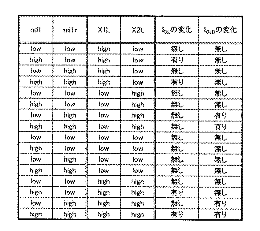
図24Aに示す回路MPは、図5Fの回路MPに適用できる回路の一例である。
本実施の形態では、上記実施の形態で説明した半導体装置に適用可能なOSトランジスタの構成例について説明する。
図28に示す半導体装置は、トランジスタ300と、トランジスタ500と、容量素子600と、を有している。図30Aはトランジスタ500のチャネル長方向の断面図であり、図30Bはトランジスタ500のチャネル幅方向の断面図であり、図30Cはトランジスタ300のチャネル幅方向の断面図である。
なお、本実施の形態に示す半導体装置のトランジスタ500は、上記の構造に限られるものではない。以下、トランジスタ500に用いることができる構造例について説明する。なお、下記に説明するトランジスタは、上記に説明したトランジスタの変形例であるため、下記の説明では、異なる点を主に説明し、同一の点については省略することがある。
図31A乃至図31Cを用いてトランジスタ500Aの構造例を説明する。図31Aはトランジスタ500Aの上面図である。図31Bは、図31Aに一点鎖線L1−L2で示す部位の断面図である。図31Cは、図31Aに一点鎖線W1−W2で示す部位の断面図である。なお、図31Aの上面図では、図の明瞭化のために一部の要素を省いて図示している。
図32A乃至図32Cを用いてトランジスタ500Bの構造例を説明する。図32Aはトランジスタ500Bの上面図である。図32Bは、図32Aに一点鎖線L1−L2で示す部位の断面図である。図32Cは、図32Aに一点鎖線W1−W2で示す部位の断面図である。なお、図32Aの上面図では、図の明瞭化のために一部の要素を省いて図示している。
図33A乃至図33Cを用いてトランジスタ500Cの構造例を説明する。図33Aはトランジスタ500Cの上面図である。図33Bは、図33Aに一点鎖線L1−L2で示す部位の断面図である。図33Cは、図33Aに一点鎖線W1−W2で示す部位の断面図である。なお、図33Aの上面図では、図の明瞭化のために一部の要素を省いて図示している。
図34A乃至図34Cを用いてトランジスタ500Dの構造例を説明する。図34Aはトランジスタ500Dの上面図である。図34Bは、図34Aに一点鎖線L1−L2で示す部位の断面図である。図34Cは、図34Aに一点鎖線W1−W2で示す部位の断面図である。なお、図34Aの上面図では、図の明瞭化のために一部の要素を省いて図示している。
図35A乃至図35Cを用いてトランジスタ500Eの構造例を説明する。図35Aはトランジスタ500Eの上面図である。図35Bは、図35Aに一点鎖線L1−L2で示す部位の断面図である。図35Cは、図35Aに一点鎖線W1−W2で示す部位の断面図である。なお、図35Aの上面図では、図の明瞭化のために一部の要素を省いて図示している。
また、図30A、及び図30Bでは、ゲートとして機能する導電体560が、絶縁体580の開口の内部に形成されている構造例について説明したが、例えば、当該導電体の上方に、当該絶縁体が設けられた構造を用いることもできる。このようなトランジスタの構造例を、図36A、図36B、図37A、図37Bに示す。
図38A乃至図38Cでは、図28に示す半導体装置に適用できる容量素子600の一例として容量素子600Aについて示している。図38Aは容量素子600Aの上面図であり、図38Bは容量素子600Aの一点鎖線L3−L4における断面を示した斜視図であり、図38Cは容量素子600Aの一点鎖線W3−L4における断面を示した斜視図である。
本実施の形態では、上記の実施の形態で説明したOSトランジスタに用いることができる金属酸化物であるCAC−OS(Cloud−Aligned Composite Oxide Semiconductor)、及びCAAC−OS(c−axis Aligned Crystalline Oxide Semiconductor)の構成について説明する。なお、本明細書等において、CACは機能、または材料の構成の一例を表し、CAACは結晶構造の一例を表す。
CAC−OS又はCAC−metal oxideとは、材料の一部では導電性の機能と、材料の一部では絶縁性の機能とを有し、材料の全体では半導体としての機能を有する。なお、CAC−OS又はCAC−metal oxideを、トランジスタの活性層に用いる場合、導電性の機能は、キャリアとなる電子(又はホール)を流す機能であり、絶縁性の機能は、キャリアとなる電子を流さない機能である。導電性の機能と、絶縁性の機能とを、それぞれ相補的に作用させることで、スイッチングさせる機能(On/Offさせる機能)をCAC−OS又はCAC−metal oxideに付与することができる。CAC−OS又はCAC−metal oxideにおいて、それぞれの機能を分離させることで、双方の機能を最大限に高めることができる。
酸化物半導体は、単結晶酸化物半導体と、それ以外の非単結晶酸化物半導体と、に分けられる。非単結晶酸化物半導体としては、例えば、CAAC−OS(c−axis aligned crystalline oxide semiconductor)、多結晶酸化物半導体、nc−OS(nanocrystalline oxide semiconductor)、擬似非晶質酸化物半導体(a−like OS:amorphous−like oxide semiconductor)及び非晶質酸化物半導体などがある。
続いて、上記酸化物半導体をトランジスタに用いる場合について説明する。
ここで、酸化物半導体中における各不純物の影響について説明する。
本実施の形態は、上記実施の形態に示す半導体装置などが形成された半導体ウェハ、及び当該半導体装置が組み込まれた電子部品の一例を示す。
初めに、半導体装置などが形成された半導体ウェハの例を、図40Aを用いて説明する。
次に、チップ4800aが組み込まれた電子部品の例を、図40C、図40Dを用いて説明を行う。
本実施の形態では、上記実施の形態で説明した半導体装置を有する電子機器の一例について説明する。なお、図41には、当該半導体装置を有する電子部品4700(BMP)が各電子機器に含まれている様子を図示している。
図41に示す情報端末5500は、情報端末の一種である携帯電話(スマートフォン)である。情報端末5500は、筐体5510と、表示部5511と、を有しており、入力用インターフェースとして、タッチパネルが表示部5511に備えられ、ボタンが筐体5510に備えられている。
また、図41には、ウェアラブル端末の一例として情報端末5900が図示されている。情報端末5900は、筐体5901、表示部5902、操作ボタン5903、操作子5904、バンド5905などを有する。
また、図41には、デスクトップ型情報端末5300が図示されている。デスクトップ型情報端末5300は、情報端末の本体5301と、ディスプレイ5302と、キーボード5303と、を有する。
また、図41には、電化製品の一例として電気冷凍冷蔵庫5800が図示されている。電気冷凍冷蔵庫5800は、筐体5801、冷蔵室用扉5802、冷凍室用扉5803等を有する。
また、図41には、ゲーム機の一例である携帯ゲーム機5200が図示されている。携帯ゲーム機5200は、筐体5201、表示部5202、ボタン5203等を有する。
上記実施の形態で説明した半導体装置は、移動体である自動車、及び自動車の運転席周辺に適用することができる。
上記実施の形態で説明した半導体装置は、カメラに適用することができる。
上記実施の形態で説明した半導体装置は、ビデオカメラに適用することができる。
上記実施の形態で説明した半導体装置は、PC(Personal Computer)などの計算機、情報端末用の拡張デバイスに適用することができる。
上記実施の形態で説明した半導体装置は、放送システムに適用することができる。
上記実施の形態で説明した半導体装置は、認証システムに適用することができる。
Claims (11)
- 第1回路と、第2回路と、を有する半導体装置であって、
前記第1回路は、第1保持ノードを有し、
前記第2回路は、第2保持ノードを有し、
前記第1回路は、第1入力配線、第2入力配線、第1配線、及び第2配線と電気的に接続され、
前記第2回路は、前記第1入力配線、前記第2入力配線、前記第1配線、及び前記第2配線と電気的に接続され、
前記第1回路は、第1データに応じた第1電位を前記第1保持ノードに保持する機能を有し、
前記第2回路は、前記第1データに応じた第2電位を前記第2保持ノードに保持する機能を有し、
前記第1回路は、
前記第1入力配線に高レベル電位が入力され、かつ前記第2入力配線に低レベル電位が入力されたときに、前記第1電位に応じた電流を前記第1配線に出力する機能と、
前記第1入力配線に低レベル電位が入力され、かつ前記第2入力配線に高レベル電位が入力されたときに、前記第1電位に応じた電流を前記第2配線に出力する機能と、
前記第1入力配線に低レベル電位が入力され、かつ前記第2入力配線に低レベル電位が入力されたときに、前記第1電位に応じた電流を前記第1配線、及び前記第2配線に出力しない機能と、を有し、
前記第2回路は、
前記第1入力配線に高レベル電位が入力され、かつ前記第2入力配線に低レベル電位が入力されたときに、前記第2電位に応じた電流を前記第2配線に出力する機能と、
前記第1入力配線に低レベル電位が入力され、かつ前記第2入力配線に高レベル電位が入力されたときに、前記第2電位に応じた電流を前記第1配線に出力する機能と、
前記第1入力配線に低レベル電位が入力され、かつ前記第2入力配線に低レベル電位が入力されたときに、前記第2電位に応じた電流を前記第1配線、及び前記第2配線に出力しない機能と、を有する、
半導体装置。 - 請求項1において、
前記第1回路は、第1乃至第4トランジスタと、第1容量素子と、を有し、
前記第2回路は、第5乃至第8トランジスタと、第2容量素子と、を有し、
前記第1保持ノードは、前記第1トランジスタの第1端子、前記第2トランジスタのゲート、及び前記第1容量素子の第1端子と電気的に接続され、
前記第2トランジスタの第1端子は、前記第1容量素子の第2端子と電気的に接続され、
前記第2トランジスタの第2端子は、前記第3トランジスタの第1端子、及び前記第4トランジスタの第1端子と電気的に接続され、
前記第3トランジスタのゲートは、前記第1入力配線と電気的に接続され、
前記第4トランジスタのゲートは、前記第2入力配線と電気的に接続され、
前記第3トランジスタの第2端子は、前記第1配線と電気的に接続され、
前記第4トランジスタの第2端子は、前記第2配線と電気的に接続され、
前記第2保持ノードは、前記第5トランジスタの第1端子、前記第6トランジスタのゲート、及び前記第2容量素子の第1端子と電気的に接続され、
前記第6トランジスタの第1端子は、前記第2容量素子の第2端子と電気的に接続され、
前記第6トランジスタの第2端子は、前記第7トランジスタの第1端子、及び、前記第8トランジスタの第1端子と電気的に接続され、
前記第7トランジスタのゲートは、前記第1入力配線と電気的に接続され、
前記第8トランジスタのゲートは、前記第2入力配線と電気的に接続され、
前記第7トランジスタの第2端子は、前記第2配線と電気的に接続され、
前記第8トランジスタの第2端子は、前記第1配線と電気的に接続されている、
半導体装置。 - 請求項1において、
前記第1回路は、第1乃至第4トランジスタと、第9トランジスタと、第1容量素子と、を有し、
前記第2回路は、第5乃至第8トランジスタと、第10トランジスタと、第2容量素子と、を有し、
前記第1保持ノードは、前記第1トランジスタの第1端子、前記第2トランジスタのゲート、前記第9トランジスタのゲート、及び前記第1容量素子の第1端子と電気的に接続され、
前記第1容量素子の第2端子は、前記第2トランジスタの第1端子、及び前記第9トランジスタの第1端子と電気的に接続され、
前記第2トランジスタの第2端子は、前記第3トランジスタの第1端子と電気的に接続され、
前記第9トランジスタの第2端子は、前記第4トランジスタの第1端子と電気的に接続され、
前記第3トランジスタのゲートは、前記第1入力配線と電気的に接続され、
前記第4トランジスタのゲートは、前記第2入力配線と電気的に接続され、
前記第3トランジスタの第2端子は、前記第1配線と電気的に接続され、
前記第4トランジスタの第2端子は、前記第2配線と電気的に接続され、
前記第2保持ノードは、前記第5トランジスタの第1端子、前記第6トランジスタのゲート、前記第10トランジスタのゲート、及び前記第2容量素子の第1端子と電気的に接続され、
前記第2容量素子の第2端子は、前記第6トランジスタの第1端子、及び前記第10トランジスタの第1端子と電気的に接続され、
前記第6トランジスタの第2端子は、前記第7トランジスタの第1端子と電気的に接続され、
前記第10トランジスタの第2端子は、前記第8トランジスタの第1端子と電気的に接続され、
前記第7トランジスタのゲートは、前記第1入力配線と電気的に接続され、
前記第8トランジスタのゲートは、前記第2入力配線と電気的に接続され、
前記第7トランジスタの第2端子は、前記第2配線と電気的に接続され、
前記第8トランジスタの第2端子は、前記第1配線と電気的に接続されている半導体装置。 - 請求項1において、
前記第1回路は、第1乃至第4トランジスタと、第1論理回路と、第2論理回路と、を有し、
前記第2回路は、第5乃至第8トランジスタと、第3論理回路と、第4論理回路と、を有し、
前記第1乃至第4論理回路のそれぞれは、入力端子に入力された信号の反転信号を出力端子から出力する機能を有し、
前記第1保持ノードは、前記第1論理回路の入力端子、前記第2論理回路の出力端子、前記第1トランジスタの第1端子、及び前記第2トランジスタのゲートと電気的に接続され、
前記第1論理回路の出力端子は、前記第2論理回路の入力端子と電気的に接続され、
前記第2トランジスタの第2端子は、前記第3トランジスタの第1端子、及び前記第4トランジスタの第1端子と電気的に接続され、
前記第3トランジスタのゲートは、前記第1入力配線と電気的に接続され、
前記第4トランジスタのゲートは、前記第2入力配線と電気的に接続され、
前記第3トランジスタの第2端子は、前記第1配線と電気的に接続され、
前記第4トランジスタの第2端子は、前記第2配線と電気的に接続され、
前記第2保持ノードは、前記第3論理回路の入力端子、前記第4論理回路の出力端子、前記第5トランジスタの第1端子、及び前記第6トランジスタのゲートと電気的に接続され、
前記第3論理回路の出力端子は、前記第4論理回路の入力端子と電気的に接続され、
前記第6トランジスタの第2端子は、前記第7トランジスタの第1端子、及び前記第8トランジスタの第1端子と電気的に接続され、
前記第7トランジスタのゲートは、前記第1入力配線と電気的に接続され、
前記第8トランジスタのゲートは、前記第2入力配線と電気的に接続され、
前記第7トランジスタの第2端子は、前記第2配線と電気的に接続され、
前記第8トランジスタの第2端子は、前記第1配線と電気的に接続されている半導体装置。 - 請求項1において、
前記第1回路は、第1乃至第4トランジスタと、第1論理回路と、第2論理回路と、を有し、
前記第2回路は、第6乃至第8トランジスタを有し、
前記第1論理回路、前記第2論理回路のそれぞれは、入力端子に入力された信号の反転信号を出力端子から出力する機能を有し、
前記第1保持ノードは、前記第1論理回路の入力端子、前記第2論理回路の出力端子、前記第1トランジスタの第1端子、及び前記第2トランジスタのゲートと電気的に接続され、
前記第1論理回路の出力端子は、前記第2論理回路の入力端子と電気的に接続され、
前記第2トランジスタの第2端子は、前記第3トランジスタの第1端子、及び前記第4トランジスタの第1端子と電気的に接続され、
前記第3トランジスタのゲートは、前記第1入力配線と電気的に接続され、
前記第4トランジスタのゲートは、前記第2入力配線と電気的に接続され、
前記第3トランジスタの第2端子は、前記第1配線と電気的に接続され、
前記第4トランジスタの第2端子は、前記第2配線と電気的に接続され、
前記第2保持ノードは、前記第2論理回路の入力端子、前記第1論理回路の出力端子、及び、前記第6トランジスタのゲートと電気的に接続され、
前記第6トランジスタの第2端子は、前記第7トランジスタの第1端子、及び前記第8トランジスタの第1端子と電気的に接続され、
前記第7トランジスタのゲートは、前記第1入力配線と電気的に接続され、
前記第8トランジスタのゲートは、前記第2入力配線と電気的に接続され、
前記第7トランジスタの第2端子は、前記第2配線と電気的に接続され、
前記第8トランジスタの第2端子は、前記第1配線と電気的に接続されている半導体装置。 - 第1回路と、第2回路と、を有する半導体装置であって、
前記第1回路は、第1負荷回路を有し、
前記第2回路は、第2負荷回路を有し、
前記第1負荷回路と、前記第2負荷回路と、のそれぞれは、第1端子と、第2端子と、を有し、
前記第1負荷回路と、前記第2負荷回路と、のそれぞれは、第1データに応じて第1端子と第2端子との間の抵抗値を変化する機能を有し、
前記第1回路は、第1入力配線、第2入力配線、第1配線、及び第2配線と電気的に接続され、
前記第2回路は、前記第1入力配線、前記第2入力配線、前記第1配線、及び前記第2配線と電気的に接続され、
前記第1回路は、
前記第1入力配線に高レベル電位が入力され、かつ前記第2入力配線に低レベル電位が入力されたときに、前記第1負荷回路の前記抵抗値に応じた電流を前記第1配線に出力する機能と、
前記第1入力配線に低レベル電位が入力され、かつ前記第2入力配線に高レベル電位が入力されたときに、前記第1負荷回路の前記抵抗値に応じた電流を前記第2配線に出力する機能と、
前記第1入力配線に低レベル電位が入力され、かつ前記第2入力配線に低レベル電位が入力されたときに、前記第1負荷回路の前記抵抗値に応じた電流を前記第1配線、及び前記第2配線に出力しない機能と、を有し、
前記第2回路は、
前記第1入力配線に高レベル電位が入力され、かつ前記第2入力配線に低レベル電位が入力されたときに、前記第2負荷回路の前記抵抗値に応じた電流を前記第2配線に出力する機能と、
前記第1入力配線に低レベル電位が入力され、かつ前記第2入力配線に高レベル電位が入力されたときに、前記第2負荷回路の前記抵抗値に応じた電流を前記第1配線に出力する機能と、
前記第1入力配線に低レベル電位が入力され、かつ前記第2入力配線に低レベル電位が入力されたときに、前記第2負荷回路の前記抵抗値に応じた電流を前記第1配線、及び前記第2配線に出力しない機能と、を有する半導体装置。 - 請求項6において、
前記第1回路は、第3トランジスタと、第4トランジスタと、を有し、
前記第2回路は、第7トランジスタと、第8トランジスタと、を有し、
前記第1負荷回路の第1端子は、前記第3トランジスタの第1端子、及び前記第4トランジスタの第1端子と電気的に接続され、
前記第3トランジスタのゲートは、前記第1入力配線と電気的に接続され、
前記第4トランジスタのゲートは、前記第2入力配線と電気的に接続され、
前記第3トランジスタの第2端子は、前記第1配線と電気的に接続され、
前記第4トランジスタの第2端子は、前記第2配線と電気的に接続され、
前記第2負荷回路の第1端子は、前記第7トランジスタの第1端子、及び前記第8トランジスタの第1端子と電気的に接続され、
前記第7トランジスタのゲートは、前記第1入力配線と電気的に接続され、
前記第8トランジスタのゲートは、前記第2入力配線と電気的に接続され、
前記第7トランジスタの第2端子は、前記第2配線と電気的に接続され、
前記第8トランジスタの第2端子は、前記第1配線と電気的に接続されている半導体装置。 - 請求項7において、
前記第1回路は、第1トランジスタを有し、
前記第2回路は、第2トランジスタを有し、
前記第1トランジスタの第1端子は、前記第1負荷回路の第1端子と電気的に接続され、
前記第2トランジスタの第1端子は、前記第2負荷回路の第1端子と電気的に接続されている半導体装置。 - 請求項6乃至請求項8のいずれか一において、
前記第1負荷回路は、抵抗変化素子、MTJ素子、相変化メモリのいずれか一を有し、
前記第2負荷回路は、抵抗変化素子、MTJ素子、相変化メモリのいずれか一を有する半導体装置。 - 請求項1乃至請求項9のいずれか一において、
第3回路と、第4回路と、を有し、
前記第3回路は、前記第1入力配線と、前記第2入力配線と、のそれぞれに第2データに応じた電位を入力する機能を有し、
前記第4回路は、前記第1配線と、前記第2配線と、のそれぞれから流れる電流を比較して、前記第4回路の出力端子から、前記第1データと前記第2データの積に応じた電位を出力する機能を有する半導体装置。 - 請求項1乃至請求項10のいずれか一の半導体装置を有し、
前記半導体装置によってニューラルネットワークの演算を行う電子機器。
Priority Applications (14)
| Application Number | Priority Date | Filing Date | Title |
|---|---|---|---|
| DE112019005195.4T DE112019005195T5 (de) | 2018-10-19 | 2019-10-07 | Halbleitervorrichtung und elektronisches Gerät |
| KR1020217011405A KR102891305B1 (ko) | 2018-10-19 | 2019-10-07 | 반도체 장치 및 전자 기기 |
| KR1020257039123A KR20250173579A (ko) | 2018-10-19 | 2019-10-07 | 반도체 장치 및 전자 기기 |
| CN201980068769.8A CN112868017B (zh) | 2018-10-19 | 2019-10-07 | 半导体装置及电子设备 |
| JP2020552172A JP7364586B2 (ja) | 2018-10-19 | 2019-10-07 | 半導体装置、及び電子機器 |
| US17/278,675 US11417704B2 (en) | 2018-10-19 | 2019-10-07 | Semiconductor device and electronic device |
| CN202510015116.0A CN119940437A (zh) | 2018-10-19 | 2019-10-07 | 半导体装置及电子设备 |
| US17/884,940 US11856792B2 (en) | 2018-10-19 | 2022-08-10 | Semiconductor device and electronic device |
| JP2023173441A JP7602596B2 (ja) | 2018-10-19 | 2023-10-05 | 半導体装置及び電子機器 |
| US18/391,970 US12389608B2 (en) | 2018-10-19 | 2023-12-21 | Semiconductor device and electronic device |
| JP2024213426A JP7796853B2 (ja) | 2018-10-19 | 2024-12-06 | 半導体装置及び電子機器 |
| JP2025068045A JP7842280B2 (ja) | 2018-10-19 | 2025-04-17 | 半導体装置及び電子機器 |
| US19/294,418 US20250365981A1 (en) | 2018-10-19 | 2025-08-08 | Semiconductor device and electronic device |
| JP2025279211A JP7851475B1 (ja) | 2018-10-19 | 2025-12-23 | 半導体装置、電子機器 |
Applications Claiming Priority (4)
| Application Number | Priority Date | Filing Date | Title |
|---|---|---|---|
| JP2018-197383 | 2018-10-19 | ||
| JP2018197383 | 2018-10-19 | ||
| JP2019138187 | 2019-07-26 | ||
| JP2019-138187 | 2019-07-26 |
Related Child Applications (2)
| Application Number | Title | Priority Date | Filing Date |
|---|---|---|---|
| US17/278,675 A-371-Of-International US11417704B2 (en) | 2018-10-19 | 2019-10-07 | Semiconductor device and electronic device |
| US17/884,940 Continuation US11856792B2 (en) | 2018-10-19 | 2022-08-10 | Semiconductor device and electronic device |
Publications (1)
| Publication Number | Publication Date |
|---|---|
| WO2020079523A1 true WO2020079523A1 (ja) | 2020-04-23 |
Family
ID=70284274
Family Applications (1)
| Application Number | Title | Priority Date | Filing Date |
|---|---|---|---|
| PCT/IB2019/058507 Ceased WO2020079523A1 (ja) | 2018-10-19 | 2019-10-07 | 半導体装置、及び電子機器 |
Country Status (7)
| Country | Link |
|---|---|
| US (4) | US11417704B2 (ja) |
| JP (5) | JP7364586B2 (ja) |
| KR (2) | KR102891305B1 (ja) |
| CN (2) | CN112868017B (ja) |
| DE (1) | DE112019005195T5 (ja) |
| TW (2) | TWI892324B (ja) |
| WO (1) | WO2020079523A1 (ja) |
Cited By (6)
| Publication number | Priority date | Publication date | Assignee | Title |
|---|---|---|---|---|
| CN113268944A (zh) * | 2021-05-21 | 2021-08-17 | 广东电网有限责任公司广州供电局 | 一种高耦合分裂电抗器的宽频建模方法及系统 |
| JPWO2022023866A1 (ja) * | 2020-07-31 | 2022-02-03 | ||
| US11776586B2 (en) | 2019-02-15 | 2023-10-03 | Semiconductor Energy Laboratory Co., Ltd. | Semiconductor device and electronic device |
| WO2025114843A1 (ja) * | 2023-11-30 | 2025-06-05 | 株式会社半導体エネルギー研究所 | 乗算回路、演算回路及び電子機器 |
| WO2025202848A1 (ja) * | 2024-03-29 | 2025-10-02 | 株式会社半導体エネルギー研究所 | 表示装置 |
| US12475361B2 (en) | 2019-05-17 | 2025-11-18 | Semiconductor Energy Laboratory Co., Ltd. | Semiconductor device and electronic device |
Families Citing this family (5)
| Publication number | Priority date | Publication date | Assignee | Title |
|---|---|---|---|---|
| JP2020126427A (ja) * | 2019-02-04 | 2020-08-20 | ソニー株式会社 | 演算装置、積和演算システム及び設定方法 |
| CN113471244B (zh) * | 2020-03-30 | 2023-09-12 | 联华电子股份有限公司 | 半导体元件及其制作方法 |
| US12033694B2 (en) | 2020-07-17 | 2024-07-09 | Semiconductor Energy Laboratory Co., Ltd. | Semiconductor device and electronic device |
| WO2022064303A1 (ja) | 2020-09-22 | 2022-03-31 | 株式会社半導体エネルギー研究所 | 半導体装置、及び電子機器 |
| US20230411386A1 (en) * | 2022-06-20 | 2023-12-21 | International Business Machines Corporation | Method and structure of forming contacts and gates for staggered fet |
Citations (2)
| Publication number | Priority date | Publication date | Assignee | Title |
|---|---|---|---|---|
| JPH0259956A (ja) * | 1988-08-26 | 1990-02-28 | Nippon Telegr & Teleph Corp <Ntt> | ニューラルネットワーク装置 |
| JP2018109968A (ja) * | 2016-12-28 | 2018-07-12 | 株式会社半導体エネルギー研究所 | ニューラルネットワークを利用したデータ処理装置、電子部品、および電子機器 |
Family Cites Families (23)
| Publication number | Priority date | Publication date | Assignee | Title |
|---|---|---|---|---|
| JPH0467259A (ja) | 1990-07-09 | 1992-03-03 | Hitachi Ltd | 情報処理装置 |
| JPH04281584A (ja) * | 1990-08-01 | 1992-10-07 | General Electric Co <Ge> | 複数の入力信号の重みづけられた複数の加算を行う装置 |
| US5343555A (en) | 1992-07-06 | 1994-08-30 | The Regents Of The University Of California | Artificial neuron with switched-capacitor synapses using analog storage of synaptic weights |
| JP3199707B2 (ja) | 1999-08-09 | 2001-08-20 | 株式会社半導体理工学研究センター | 半導体演算回路及び演算装置 |
| JP4393980B2 (ja) | 2004-06-14 | 2010-01-06 | シャープ株式会社 | 表示装置 |
| US7425740B2 (en) * | 2005-10-07 | 2008-09-16 | Taiwan Semiconductor Manufacturing Company, Ltd. | Method and structure for a 1T-RAM bit cell and macro |
| JP2007241475A (ja) | 2006-03-06 | 2007-09-20 | Canon Inc | 差動乗算回路及び積和演算回路 |
| JP4914771B2 (ja) * | 2007-06-01 | 2012-04-11 | エルピーダメモリ株式会社 | 半導体装置 |
| KR102087443B1 (ko) * | 2012-05-11 | 2020-03-10 | 가부시키가이샤 한도오따이 에네루기 켄큐쇼 | 반도체 장치 및 그 구동 방법 |
| US9466362B2 (en) * | 2014-08-12 | 2016-10-11 | Arizona Board Of Regents On Behalf Of Arizona State University | Resistive cross-point architecture for robust data representation with arbitrary precision |
| US10522693B2 (en) * | 2015-01-16 | 2019-12-31 | Semiconductor Energy Laboratory Co., Ltd. | Memory device and electronic device |
| TWI688211B (zh) | 2015-01-29 | 2020-03-11 | 日商半導體能源研究所股份有限公司 | 半導體裝置、電子組件及電子裝置 |
| JP6674838B2 (ja) | 2015-05-21 | 2020-04-01 | 株式会社半導体エネルギー研究所 | 電子装置 |
| JP6758037B2 (ja) * | 2015-10-16 | 2020-09-23 | ローム株式会社 | チョッパ安定化アンプ |
| CN121981182A (zh) | 2015-10-23 | 2026-05-05 | 株式会社半导体能源研究所 | 半导体装置及电子设备 |
| JP2017108397A (ja) | 2015-11-30 | 2017-06-15 | 株式会社半導体エネルギー研究所 | 信号処理回路、及び該信号処理回路を有する半導体装置 |
| US10664748B2 (en) * | 2016-03-18 | 2020-05-26 | Semiconductor Energy Laboratory Co., Ltd. | Semiconductor device and system using the same |
| DE112017003050B4 (de) | 2016-06-20 | 2026-05-07 | Sony Corporation | Anzeigeeinrichtung und elektronische Einrichtung |
| WO2018069785A1 (en) | 2016-10-12 | 2018-04-19 | Semiconductor Energy Laboratory Co., Ltd. | Semiconductor device and system using the same |
| TWI748035B (zh) * | 2017-01-20 | 2021-12-01 | 日商半導體能源硏究所股份有限公司 | 顯示系統及電子裝置 |
| WO2018138603A1 (en) | 2017-01-26 | 2018-08-02 | Semiconductor Energy Laboratory Co., Ltd. | Semiconductor device and electronic device including the semiconductor device |
| US20200006567A1 (en) | 2017-02-15 | 2020-01-02 | Semiconductor Energy Laboratory Co., Ltd. | Semiconductor device |
| WO2018215882A1 (ja) * | 2017-05-26 | 2018-11-29 | 株式会社半導体エネルギー研究所 | 撮像装置および電子機器 |
-
2019
- 2019-10-07 CN CN201980068769.8A patent/CN112868017B/zh active Active
- 2019-10-07 JP JP2020552172A patent/JP7364586B2/ja active Active
- 2019-10-07 KR KR1020217011405A patent/KR102891305B1/ko active Active
- 2019-10-07 DE DE112019005195.4T patent/DE112019005195T5/de active Pending
- 2019-10-07 WO PCT/IB2019/058507 patent/WO2020079523A1/ja not_active Ceased
- 2019-10-07 KR KR1020257039123A patent/KR20250173579A/ko active Pending
- 2019-10-07 CN CN202510015116.0A patent/CN119940437A/zh active Pending
- 2019-10-07 US US17/278,675 patent/US11417704B2/en active Active
- 2019-10-09 TW TW112145952A patent/TWI892324B/zh active
- 2019-10-09 TW TW108136531A patent/TWI827696B/zh active
-
2022
- 2022-08-10 US US17/884,940 patent/US11856792B2/en active Active
-
2023
- 2023-10-05 JP JP2023173441A patent/JP7602596B2/ja active Active
- 2023-12-21 US US18/391,970 patent/US12389608B2/en active Active
-
2024
- 2024-12-06 JP JP2024213426A patent/JP7796853B2/ja active Active
-
2025
- 2025-04-17 JP JP2025068045A patent/JP7842280B2/ja active Active
- 2025-08-08 US US19/294,418 patent/US20250365981A1/en active Pending
- 2025-12-23 JP JP2025279211A patent/JP7851475B1/ja active Active
Patent Citations (2)
| Publication number | Priority date | Publication date | Assignee | Title |
|---|---|---|---|---|
| JPH0259956A (ja) * | 1988-08-26 | 1990-02-28 | Nippon Telegr & Teleph Corp <Ntt> | ニューラルネットワーク装置 |
| JP2018109968A (ja) * | 2016-12-28 | 2018-07-12 | 株式会社半導体エネルギー研究所 | ニューラルネットワークを利用したデータ処理装置、電子部品、および電子機器 |
Cited By (8)
| Publication number | Priority date | Publication date | Assignee | Title |
|---|---|---|---|---|
| US11776586B2 (en) | 2019-02-15 | 2023-10-03 | Semiconductor Energy Laboratory Co., Ltd. | Semiconductor device and electronic device |
| US12518800B2 (en) | 2019-02-15 | 2026-01-06 | Semiconductor Energy Laboratory Co., Ltd. | Semiconductor device performing arithmetic operation |
| US12475361B2 (en) | 2019-05-17 | 2025-11-18 | Semiconductor Energy Laboratory Co., Ltd. | Semiconductor device and electronic device |
| JPWO2022023866A1 (ja) * | 2020-07-31 | 2022-02-03 | ||
| JP7724221B2 (ja) | 2020-07-31 | 2025-08-15 | 株式会社半導体エネルギー研究所 | 半導体装置 |
| CN113268944A (zh) * | 2021-05-21 | 2021-08-17 | 广东电网有限责任公司广州供电局 | 一种高耦合分裂电抗器的宽频建模方法及系统 |
| WO2025114843A1 (ja) * | 2023-11-30 | 2025-06-05 | 株式会社半導体エネルギー研究所 | 乗算回路、演算回路及び電子機器 |
| WO2025202848A1 (ja) * | 2024-03-29 | 2025-10-02 | 株式会社半導体エネルギー研究所 | 表示装置 |
Also Published As
| Publication number | Publication date |
|---|---|
| JP2025038015A (ja) | 2025-03-18 |
| JP2025114599A (ja) | 2025-08-05 |
| JP2026075093A (ja) | 2026-05-07 |
| JPWO2020079523A1 (ja) | 2020-04-23 |
| CN112868017A (zh) | 2021-05-28 |
| US20220384522A1 (en) | 2022-12-01 |
| JP7796853B2 (ja) | 2026-01-09 |
| US11417704B2 (en) | 2022-08-16 |
| TWI827696B (zh) | 2024-01-01 |
| JP7364586B2 (ja) | 2023-10-18 |
| US20240147733A1 (en) | 2024-05-02 |
| DE112019005195T5 (de) | 2021-07-08 |
| US20220045125A1 (en) | 2022-02-10 |
| CN119940437A (zh) | 2025-05-06 |
| KR20250173579A (ko) | 2025-12-10 |
| US20250365981A1 (en) | 2025-11-27 |
| KR20210080381A (ko) | 2021-06-30 |
| JP7842280B2 (ja) | 2026-04-07 |
| JP7602596B2 (ja) | 2024-12-18 |
| US12389608B2 (en) | 2025-08-12 |
| KR102891305B1 (ko) | 2025-11-27 |
| TW202435116A (zh) | 2024-09-01 |
| CN112868017B (zh) | 2025-02-21 |
| TWI892324B (zh) | 2025-08-01 |
| TW202022681A (zh) | 2020-06-16 |
| JP7851475B1 (ja) | 2026-04-24 |
| JP2024016027A (ja) | 2024-02-06 |
| US11856792B2 (en) | 2023-12-26 |
Similar Documents
| Publication | Publication Date | Title |
|---|---|---|
| JP7602596B2 (ja) | 半導体装置及び電子機器 | |
| JP7854547B2 (ja) | 半導体装置 | |
| JP7671888B2 (ja) | 半導体装置 | |
| JP7819385B2 (ja) | 半導体装置および電子機器 | |
| JP7562785B2 (ja) | 半導体装置、電子機器 | |
| KR20230041718A (ko) | 반도체 장치 및 전자 기기 | |
| TW202616133A (zh) | 半導體裝置及電子裝置 |
Legal Events
| Date | Code | Title | Description |
|---|---|---|---|
| 121 | Ep: the epo has been informed by wipo that ep was designated in this application |
Ref document number: 19873512 Country of ref document: EP Kind code of ref document: A1 |
|
| ENP | Entry into the national phase |
Ref document number: 2020552172 Country of ref document: JP Kind code of ref document: A |
|
| ENP | Entry into the national phase |
Ref document number: 20217011405 Country of ref document: KR Kind code of ref document: A |
|
| 122 | Ep: pct application non-entry in european phase |
Ref document number: 19873512 Country of ref document: EP Kind code of ref document: A1 |
|
| WWG | Wipo information: grant in national office |
Ref document number: 201980068769.8 Country of ref document: CN |