WO2020071488A1 - 薄肉鋳片の製造方法 - Google Patents
薄肉鋳片の製造方法Info
- Publication number
- WO2020071488A1 WO2020071488A1 PCT/JP2019/039126 JP2019039126W WO2020071488A1 WO 2020071488 A1 WO2020071488 A1 WO 2020071488A1 JP 2019039126 W JP2019039126 W JP 2019039126W WO 2020071488 A1 WO2020071488 A1 WO 2020071488A1
- Authority
- WO
- WIPO (PCT)
- Prior art keywords
- molten steel
- temperature
- tundish
- cast slab
- thin cast
- Prior art date
- Legal status (The legal status is an assumption and is not a legal conclusion. Google has not performed a legal analysis and makes no representation as to the accuracy of the status listed.)
- Ceased
Links
Images
Classifications
-
- B—PERFORMING OPERATIONS; TRANSPORTING
- B22—CASTING; POWDER METALLURGY
- B22D—CASTING OF METALS; CASTING OF OTHER SUBSTANCES BY THE SAME PROCESSES OR DEVICES
- B22D11/00—Continuous casting of metals, i.e. casting in indefinite lengths
- B22D11/10—Supplying or treating molten metal
- B22D11/108—Feeding additives, powders, or the like
-
- B—PERFORMING OPERATIONS; TRANSPORTING
- B22—CASTING; POWDER METALLURGY
- B22D—CASTING OF METALS; CASTING OF OTHER SUBSTANCES BY THE SAME PROCESSES OR DEVICES
- B22D1/00—Treatment of fused masses in the ladle or the supply runners before casting
-
- B—PERFORMING OPERATIONS; TRANSPORTING
- B22—CASTING; POWDER METALLURGY
- B22D—CASTING OF METALS; CASTING OF OTHER SUBSTANCES BY THE SAME PROCESSES OR DEVICES
- B22D1/00—Treatment of fused masses in the ladle or the supply runners before casting
- B22D1/007—Treatment of the fused masses in the supply runners
-
- B—PERFORMING OPERATIONS; TRANSPORTING
- B22—CASTING; POWDER METALLURGY
- B22D—CASTING OF METALS; CASTING OF OTHER SUBSTANCES BY THE SAME PROCESSES OR DEVICES
- B22D11/00—Continuous casting of metals, i.e. casting in indefinite lengths
- B22D11/06—Continuous casting of metals, i.e. casting in indefinite lengths into moulds with travelling walls, e.g. with rolls, plates, belts, caterpillars
-
- B—PERFORMING OPERATIONS; TRANSPORTING
- B22—CASTING; POWDER METALLURGY
- B22D—CASTING OF METALS; CASTING OF OTHER SUBSTANCES BY THE SAME PROCESSES OR DEVICES
- B22D11/00—Continuous casting of metals, i.e. casting in indefinite lengths
- B22D11/06—Continuous casting of metals, i.e. casting in indefinite lengths into moulds with travelling walls, e.g. with rolls, plates, belts, caterpillars
- B22D11/0622—Continuous casting of metals, i.e. casting in indefinite lengths into moulds with travelling walls, e.g. with rolls, plates, belts, caterpillars formed by two casting wheels
-
- B—PERFORMING OPERATIONS; TRANSPORTING
- B22—CASTING; POWDER METALLURGY
- B22D—CASTING OF METALS; CASTING OF OTHER SUBSTANCES BY THE SAME PROCESSES OR DEVICES
- B22D11/00—Continuous casting of metals, i.e. casting in indefinite lengths
- B22D11/06—Continuous casting of metals, i.e. casting in indefinite lengths into moulds with travelling walls, e.g. with rolls, plates, belts, caterpillars
- B22D11/0637—Accessories therefor
- B22D11/0648—Casting surfaces
- B22D11/0651—Casting wheels
-
- B—PERFORMING OPERATIONS; TRANSPORTING
- B22—CASTING; POWDER METALLURGY
- B22D—CASTING OF METALS; CASTING OF OTHER SUBSTANCES BY THE SAME PROCESSES OR DEVICES
- B22D11/00—Continuous casting of metals, i.e. casting in indefinite lengths
- B22D11/06—Continuous casting of metals, i.e. casting in indefinite lengths into moulds with travelling walls, e.g. with rolls, plates, belts, caterpillars
- B22D11/0637—Accessories therefor
- B22D11/068—Accessories therefor for cooling the cast product during its passage through the mould surfaces
- B22D11/0682—Accessories therefor for cooling the cast product during its passage through the mould surfaces by cooling the casting wheel
-
- B—PERFORMING OPERATIONS; TRANSPORTING
- B22—CASTING; POWDER METALLURGY
- B22D—CASTING OF METALS; CASTING OF OTHER SUBSTANCES BY THE SAME PROCESSES OR DEVICES
- B22D11/00—Continuous casting of metals, i.e. casting in indefinite lengths
- B22D11/10—Supplying or treating molten metal
-
- B—PERFORMING OPERATIONS; TRANSPORTING
- B22—CASTING; POWDER METALLURGY
- B22D—CASTING OF METALS; CASTING OF OTHER SUBSTANCES BY THE SAME PROCESSES OR DEVICES
- B22D11/00—Continuous casting of metals, i.e. casting in indefinite lengths
- B22D11/16—Controlling or regulating processes or operations
- B22D11/165—Controlling or regulating processes or operations for the supply of casting powder
-
- B—PERFORMING OPERATIONS; TRANSPORTING
- B22—CASTING; POWDER METALLURGY
- B22D—CASTING OF METALS; CASTING OF OTHER SUBSTANCES BY THE SAME PROCESSES OR DEVICES
- B22D11/00—Continuous casting of metals, i.e. casting in indefinite lengths
- B22D11/16—Controlling or regulating processes or operations
- B22D11/18—Controlling or regulating processes or operations for pouring
- B22D11/181—Controlling or regulating processes or operations for pouring responsive to molten metal level or slag level
- B22D11/182—Controlling or regulating processes or operations for pouring responsive to molten metal level or slag level by measuring temperature
-
- Y—GENERAL TAGGING OF NEW TECHNOLOGICAL DEVELOPMENTS; GENERAL TAGGING OF CROSS-SECTIONAL TECHNOLOGIES SPANNING OVER SEVERAL SECTIONS OF THE IPC; TECHNICAL SUBJECTS COVERED BY FORMER USPC CROSS-REFERENCE ART COLLECTIONS [XRACs] AND DIGESTS
- Y02—TECHNOLOGIES OR APPLICATIONS FOR MITIGATION OR ADAPTATION AGAINST CLIMATE CHANGE
- Y02P—CLIMATE CHANGE MITIGATION TECHNOLOGIES IN THE PRODUCTION OR PROCESSING OF GOODS
- Y02P10/00—Technologies related to metal processing
- Y02P10/20—Recycling
Definitions
- the present invention supplies molten steel to a molten steel pool formed by a pair of rotating cooling rolls and a pair of side weirs through an immersion nozzle, forms and grows a solidified shell on the peripheral surface of the cooling roll, and has a thin wall.
- the present invention relates to a method for producing a thin cast slab for producing a cast slab.
- a pair of cooling rolls having a water cooling structure inside and rotating in opposite directions to each other is provided.
- the molten steel is supplied to the molten steel pool formed by the refractory walls, and a solidified shell is formed and grown on the peripheral surface of the cooling roll.
- a twin-roll continuous casting apparatus for producing a thin cast slab having a predetermined thickness by pressure bonding.
- the equiaxed crystal ratio is defined as the ratio of the thickness of the equiaxed crystal zone to the total thickness of the slab.
- the equiaxed crystal ratio is 0%, that is, when it is composed of only columnar crystals, porosity and center segregation tend to be easily generated in the 1 / thick portion.
- the equiaxed crystal ratio is related to the molten steel temperature. Table 1 shows an example of the relationship between the superheat degree ⁇ T of molten steel in a tundish and the equiaxed crystal ratio in a low carbon steel.
- the equiaxed crystal ratio is strictly affected by the temperature of the molten steel pool described above. However, since it is generally difficult to measure the temperature of the molten steel pool, it is controlled by the temperature of the molten steel in the tundish. Since the amount of temperature drop accompanying the supply of molten steel from the tundish to the molten steel pool is almost constant depending on the individual continuous casting equipment, the relationship between the molten steel temperature in the tundish and the equiaxed crystal ratio is shown in Table 1. It is sought as shown.
- the molten steel temperature becomes too low in the early stage of casting and at the end of casting, so that the immersion nozzle is blocked. There was a risk of trouble. In addition, there is a possibility that a hot band or the like may be generated due to a large growth of the base metal, which is rolled into the thin cast slab.
- the molten steel temperature becomes excessively high in a steady state, and the equiaxed crystal ratio decreases. There was a risk.
- the present invention has been made in view of the above-described circumstances, and controls the molten steel temperature of a molten steel pool portion within a predetermined range by controlling the molten steel temperature in a tundish within a predetermined range, thereby controlling the longitudinal direction. It is an object of the present invention to provide a method for producing a thin cast slab in which a thin cast slab having a stable equiaxed crystal ratio can be produced.
- the method for manufacturing a thin cast slab according to the present invention includes a molten steel pool formed by a pair of rotating cooling rolls and a pair of side dams, and molten steel stored in a tundish.
- the Si concentration of the molten steel is kept constant by adding the Si additive containing Si, which generates heat when dissolved in Fe, to the molten steel in the tundish. Since the temperature is adjusted within the range and the temperature of the molten steel in the tundish is controlled within a certain range, the temperature of the molten steel can be accurately controlled, and the equiaxed crystal ratio in the longitudinal direction is reduced. A stable thin cast piece can be manufactured. In addition, even at the beginning of casting or at the end of casting when the temperature of the molten steel is low, the temperature of the molten steel can be increased by adding the Si additive, and the occurrence of troubles such as clogging of the immersion nozzle can be suppressed. It can be performed. For this reason, the molten steel temperature in a steady state can be set low, and a thin cast slab having a target equiaxed crystal ratio can be manufactured.
- a plurality of Si-containing materials having different Si contents are prepared, and a single or a plurality of the Si-containing materials are mixed with the molten steel in the tundish. It is preferable to adjust the ratio and to add the Si additive.
- the Si concentration of the molten steel is relatively easily adjusted within a certain range.
- the addition rate of the Si additive is adjusted according to the compounding ratio of the single or multiple Si-containing materials, so that the Si concentration of the molten steel is kept constant. Can be within range.
- the Si additive may be added to the molten steel in the tundish after being heated to a temperature higher than room temperature. It is possible to raise the temperature of molten steel.
- the molten steel temperature in the molten steel pool portion is controlled within a certain range by controlling the molten steel temperature in the tundish within a certain range, and the equiaxed crystal ratio in the longitudinal direction is increased. It is possible to provide a method for producing a thin cast slab capable of producing a stable thin cast slab.
- FIG. 4 is an explanatory diagram showing a result of adjusting a compounding ratio of a plurality of Si-containing materials in one embodiment of the present invention.
- the Si-containing material and the Si additive are used at room temperature or at 25 ° C.
- the thin cast slab 1 manufactured in the present embodiment is, for example, Si-containing steel containing Si in a range of 0.5% by mass to 8.0% by mass.
- the width of the thin cast slab 1 to be manufactured is in the range of 200 mm to 1800 mm, and the thickness is in the range of 0.8 mm to 5 mm.
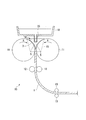
- the twin-roll continuous casting apparatus 10 shown in FIG. 1 includes a pair of cooling rolls 11, 11, pinch rolls 12, 12, and 13, 13 supporting the thin cast slab 1, and a pair of cooling rolls 11, 11.
- the molten steel 3 is supplied from the tundish 18 to the molten steel pool 16 via the immersion nozzle 20.
- the molten steel 3 contacts the rotating cooling rolls 11, 11 and is cooled, so that the solidified shells 5, 5 grow on the peripheral surfaces of the cooling rolls 11, 11. Then, the solidified shells 5, 5 formed on the pair of cooling rolls 11, 11 are pressed against each other at the roll kiss point, whereby the thin cast piece 1 having a predetermined thickness is cast.
- the temperature of the refractory constituting the tundish 18 and the like is low, so that the heat of the molten steel 3 is transmitted to the refractory side, and The temperature tends to decrease. Also, at the end of casting, the temperature of molten steel tends to decrease with time. That is, when casting is performed using the twin-roll continuous casting apparatus 10 described above, the molten steel temperature is usually low in the initial casting, high in the steady state, and low in the final casting.
- the molten steel 3 in the tundish 18 is supplied to the molten steel pool section 16 by using the immersion nozzle 20. Blockage occurs, making it difficult to perform casting stably.
- the side weir 15 is always in sliding contact with the cooling roll 11, heat is removed from the cooling roll 11 and cooled. For this reason, the metal tends to be easily generated on the surface of the side weir 15.
- the temperature of molten steel is lowered, ingots are more likely to be generated. Casting cannot be performed stably. Further, when the molten steel temperature fluctuates, the equiaxed crystal ratio changes, and the structure becomes unstable in the longitudinal direction.
- a molten steel 3 is added to the molten steel 3 in the tundish 18 by utilizing the heat generated when Si dissolves in Fe. Control the temperature. At this time, it is necessary to adjust the addition amount of the Si additive so that the Si concentration of the molten steel 3 falls within a target range. That is, in the method of manufacturing a thin cast slab according to the present embodiment, the Si additive is added to the molten steel 3 in the tundish 18 to adjust the Si concentration of the molten steel 3 within a certain range. The molten steel temperature in the tundish 18 is controlled within a certain range, and thus the molten steel temperature of the molten steel pool 16 is controlled within a certain range.
- the Si concentration of the molten steel 3 supplied into the tundish 18 is set lower than the product target Si concentration.
- the addition amount is too large, and the concentration and temperature adjustment accuracy is reduced. This is because there is a risk of doing so.
- the addition amount of the Si additive is defined by the following equation.
- the symbols in the expressions (1) to (4) and (4a) are defined as follows.
- Q s rate of addition of Si additive (kg / min)
- ⁇ C insufficient Si concentration difference from target Si concentration (% by mass)
- ⁇ Tj Insufficient temperature difference (° C) with respect to target molten steel temperature
- Equation (3) is an equation for adjusting the Si concentration in the molten steel 3
- equation (4) is an equation for controlling the molten steel temperature.
- Equation (4a) is an equation obtained by replacing ⁇ T in equation (4) with ⁇ T ′ (i, Tpi), and is an equation for controlling the molten steel temperature when a heated Si additive is used.
- a plurality of types of Si-containing materials having different Si contents are used as the Si additive, and the subscript i corresponds to each Si-containing material.
- the suffix j corresponds to the casting time.
- the Si of the molten steel 3 is increased.
- the concentration can be adjusted within a certain range, and the temperature of the molten steel in the tundish 18 can be controlled within a certain range, so that the temperature of the molten steel in the molten steel pool section 16 can be controlled within a certain range.
- the addition rate Q s (kg / min) of the Si additive is adjusted.
- the Si concentration of the molten steel 3 can be kept within a certain range even if it varies depending on the timing.
- the Si additive may be added after being heated to a temperature exceeding normal temperature.
- what degree of heating the molten steel temperature per addition increases when heated to what degree, that is, the Si concentration is reduced to 1% by mass by solely adding a unit amount of the heated Si-containing material i.
- the amount of temperature rise (° C.) of the molten steel at the time of raising the temperature may be set in advance by an experiment, a computer simulation, or the like.
- the Si-containing material constituting the Si additive it is preferable to use metallic Si and ferrosilicon as the Si-containing material constituting the Si additive.
- the ferrosilicon may be specified in Japanese Industrial Standard JIS2302-1998, or may be specified in International Standard ISO5444-1980. It is preferable to use metal Si having a purity of 95% by mass or more. Further, in ferrosilicon, if the Si content is less than 40% by mass, there is no effect of raising the temperature of the molten steel 3, and therefore, it is preferable to use a ferrosilicon having a Si content of 40% by mass or more. Ferrosilicon having a Si content of less than 40% by mass can be used when lowering the molten steel temperature or when increasing the Si concentration without changing the molten steel temperature.
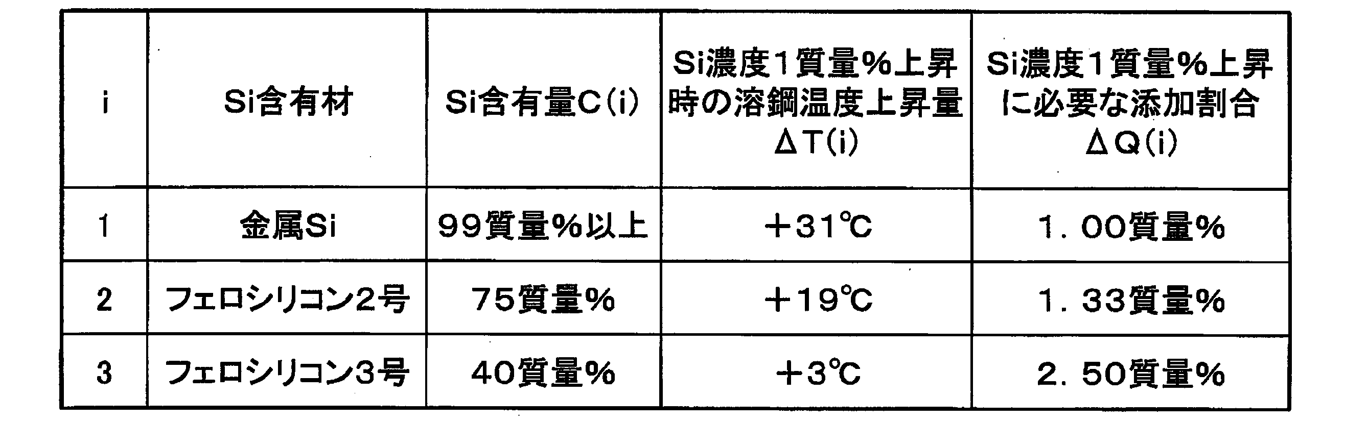
- metal Si, ferrosilicon No. 2 and ferrosilicon No. 3 are used as the Si-containing material.
- metal Si purity: 99% by mass
- the addition ratio is 1.00% by mass
- the temperature increase of the molten steel is + 31 ° C.
- Ferrosilicon No. 2 (75% by mass of Si)
- the addition ratio is 1.33% by mass
- the temperature rise of the molten steel is + 19 ° C.
- Ferrosilicon No. 3 is 40 to 45% by mass of Si, 0.2% by mass or less of C, 0.05% by mass or less of P, and 0.02% by mass or less of S in Japanese Industrial Standard JIS2302-1998.
- Is ferrosilicon defined by the chemical composition of In Ferrosilicon No. 3 Si content 40% by mass
- Ferrosilicon No. 3 is 40 to 45% by mass of Si, 0.2% by mass or less of C, 0.05% by mass or less of P, and 0.02% by mass or less of S in Japanese Industrial Standard JIS2302-1998.
- the amount of temperature rise (° C.) of the molten steel when the Si concentration is increased by 1% by mass changes depending on the Si content in the Si-containing material.
- the temperature of the molten steel can be adjusted.
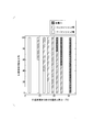
- FIG. 2 shows an example of the relationship between the compounding ratio and the temperature rise (° C.) of the molten steel when the Si concentration increases by 1% by mass. It is confirmed that the molten steel temperature can be arbitrarily controlled by selecting the mixing ratio of a plurality of Si-containing materials.
- the measurement of the molten steel temperature be continuously performed by a thermocouple disposed on the wall surface of the tundish 18.
- a consumable temperature measuring probe may be inserted from above the tundish 18 to measure the temperature intermittently. If the casting conditions such as the capacity of the tundish 18 and the throughput of the molten steel are constant, the temperature change of the molten steel in the case where the Si additive is not added is obtained in advance, and the temperature is measured by the temperature measuring probe only at the beginning of casting. Is also good.
- the method for manufacturing a thin cast slab of the present embodiment having the above-described configuration, by adding the Si additive to the molten steel 3 in the tundish 18 from the initial stage of casting to the final stage of casting, Since the Si concentration of the molten steel 3 is adjusted within a certain range and the temperature of the molten steel 3 in the tundish 18 is controlled within a certain range, the temperature of the molten steel can be accurately controlled, and the longitudinal axis is equiaxial. A thin cast slab with a stable crystallinity can be manufactured.
- the molten steel temperature low, the formation of equiaxed crystals can be promoted, and the molten steel temperature can be increased by adding the Si additive even in the early casting stage or the last casting stage when the molten steel temperature becomes low. Therefore, it is possible to suppress occurrence of troubles such as formation of a hot band due to clogging of the immersion nozzle and entrapment of the base metal, and stable casting can be performed.
- a plurality of Si-containing materials having different Si contents are prepared, and the mixing ratio of the single or these Si-containing materials to the molten steel 3 in the tundish 18 is adjusted. Therefore, it is relatively easy to adjust the Si concentration of the molten steel 3 within a certain range and control the temperature of the molten steel 3 in the molten steel pool portion 16 within a certain range. It becomes possible.
- the addition rate of the Si additive may be adjusted according to the compounding ratio of the plurality of Si-containing materials.
- the Si concentration of the molten steel 3 is set within a certain range. Can be.
- the Si additive when adding a Si-containing material such as ferrosilicon as the Si additive to the molten steel 3 in the tundish 18, the Si additive is heated to a temperature exceeding room temperature. Since it is added after that, the molten steel temperature can be efficiently raised.
- a Si-containing material such as ferrosilicon as the Si additive
- the manufacturing method of the thin cast slab which is the embodiment of the present invention was specifically described, the present invention is not limited to this, and can be appropriately changed without departing from the technical idea of the present invention. is there.
- a twin-roll continuous casting apparatus provided with pinch rolls has been described as an example. May be changed.
- metal Si, ferrosilicon No. 2, and ferrosilicon No. 3 have been described as Si-containing materials, other Si-containing materials may be used.
- the Si concentration in the molten steel supplied into the tundish was set to 0.10% by mass, and the insufficient Si concentration difference ⁇ C with respect to the target Si concentration was set to 0.70% by mass.
- the Si additive was added to the molten steel in the tundish using the three types of Si-containing materials shown in Table 2.
- the temperature of the molten steel was adjusted so that the degree of superheat ⁇ T in the tundish was in an appropriate range (30 to 50 ° C.).
- the structure of the obtained thin cast slab was observed, and the equiaxed crystal ratio was measured.
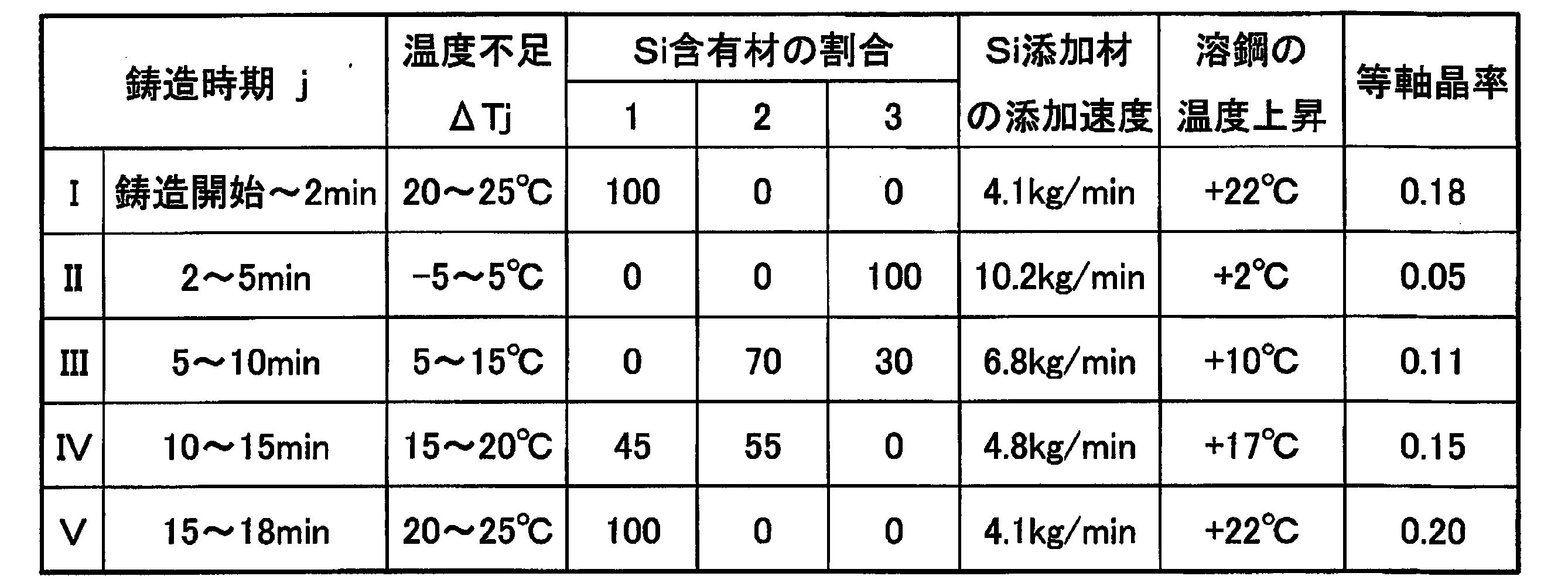
- Table 3 shows the measured equiaxed crystal ratios.
- the maximum value of the temperature rise is determined based on the insufficient Si concentration difference ⁇ C with respect to the target Si concentration.
- the maximum temperature increase ⁇ T maxi for each Si-containing material is given by the following equation from Table 2.
- the required supply amount of each Si-containing material is calculated from the equations (1) to (4). From the equation (3), the following equation (5) is calculated.
- the molten steel temperature is controlled within a certain range from the initial stage to the final stage of the casting by adding the Si additive, and the equiaxed crystal ratio is stable within the range of 0.05 to 0.20.
- the Si additive added to the molten steel temperature
- the equiaxed crystal ratio is stable within the range of 0.05 to 0.20.
- Comparative Example 1 the Si concentration in the molten steel supplied into the tundish was set to a target value of 0.80% by mass, and the superheat degree ⁇ T in the tundish at a steady state (after 5 minutes from the start of casting) was 40 ° C. Thus, the molten steel temperature was set.
- Comparative Example 1 when the molten steel was supplied into the tundish in the early stage of casting, heat was taken by the refractory of the tundish, and the molten steel temperature was lowered by about 20 to 40 ° C. as compared with the normal state. For this reason, metal was generated, and surface flaws and hot bands were generated. Also, in the final stage of casting, the temperature of the molten steel was lowered by about 20 to 40 ° C. as compared with the steady state, metal was generated, and surface flaws and hot bands were generated.
- Comparative Example 2 the Si concentration in the molten steel supplied into the tundish was set to the target value of 0.80% by mass, and the degree of superheat ⁇ T in the tundish at a steady state (after 5 minutes from the start of casting) was 60 ° C. Thus, the molten steel temperature was set.
- the molten steel temperature of the molten steel pool portion is controlled within a certain range, and the thin cast slab having a stable equiaxed crystal ratio in the longitudinal direction. Can be applied to a method for producing a thin cast slab.
Landscapes
- Engineering & Computer Science (AREA)
- Mechanical Engineering (AREA)
- Continuous Casting (AREA)
Abstract
Description
本願は、2018年10月3日に、日本に出願された特願2018-188404号に基づき優先権を主張し、その内容をここに援用する。
等軸晶率は、溶鋼温度と関係があることが知られている。表1に、低炭素鋼におけるタンディッシュ内の溶鋼の過熱度ΔTと等軸晶率との関係の一例を示す。

上述の双ロール式連続鋳造装置においては、例えば、鋳造初期には、タンディッシュ等の耐火物に熱が取られていまい、溶鋼温度が低下してしまう。定常時には溶鋼温度が高くなるが、鋳造末期には、再度、溶鋼温度が低下する傾向にある。
一方、鋳造初期、及び、鋳造末期の鋳造トラブルの発生を抑制するために、溶鋼の設定温度を高くした場合には、定常時において溶鋼温度が高くなりすぎて、等軸晶率が低くなってしまうおそれがあった。
また、溶鋼温度が低くなる鋳造初期や鋳造末期においても、Si添加材の添加によって溶鋼温度を上昇させることができ、浸漬ノズルの閉塞等のトラブルの発生を抑制することができ、安定して鋳造を行うことができる。このため、定常時における溶鋼温度を低く設定することができ、目標の等軸晶率を有する薄肉鋳片を製造することができる。
この場合、Si含有量が異なる複数のSi含有材の配合比を調整して、タンディッシュ内の溶鋼に添加することで、比較的容易に、前記溶鋼のSi濃度を一定の範囲内に調整するとともに、前記タンディッシュ内の溶鋼温度を一定の範囲内に制御することを可能にし、これにより、前記溶鋼プール部の前記溶鋼の温度を一定の範囲内に制御することが可能となる。
本実施形態において製造される薄肉鋳片1は、例えば、Siを0.5質量%以上8.0質量%以下の範囲で含むSi含有鋼とされている。
また、本実施形態では、製造される薄肉鋳片1の幅が200mm以上1800mm以下の範囲内、厚さが0.8mm以上5mm以下の範囲内とされている。
図1に示す双ロール式連続鋳造装置10は、一対の冷却ロール11、11と、薄肉鋳片1を支持するピンチロール12、12、および、13、13と、一対の冷却ロール11、11の幅方向端部に配設されたサイド堰15と、これら一対の冷却ロール11、11とサイド堰15とによって構成された溶鋼プール部16に供給される溶鋼3を保持するタンディッシュ18と、このタンディッシュ18内に貯留された溶鋼3を溶鋼プール部16へ供給する浸漬ノズル20と、を備えている。
また、上述の双ロール式連続鋳造装置10においては、サイド堰15は、冷却ロール11と常に摺接していることから、冷却ロール11から抜熱されて冷却される。このため、サイド堰15の表面に地金が発生しやすい傾向にある。鋳造初期や鋳造末期において、溶鋼温度が低下した場合には、地金がさらに発生しやすくなり、この地金が大きく成長した状態で薄肉鋳片1に巻き込まれると、ホットバンド等が発生し、安定して鋳造を行うことができなくなる。
さらに、溶鋼温度が変動すると、等軸晶率が変化することになり、長手方向で組織が不安定となる。
このとき、溶鋼3のSi濃度が目的の範囲内となるように、Si添加材の添加量を調整する必要がある。
すなわち、本実施形態である薄肉鋳片の製造方法においては、タンディッシュ18内の溶鋼3に対して、Si添加材を添加して、溶鋼3のSi濃度を一定の範囲内に調整するとともに、タンディッシュ18内の溶鋼温度を一定の範囲内に制御し、もって、溶鋼プール部16の溶鋼温度を一定の範囲内に制御する。
タンディッシュ18内に供給される溶鋼3のSi濃度と製品目標のSi濃度との差が0.5質量%未満では、添加量が少なく、温度上昇量が少なすぎるために、本発明の実施効果を実際上享受できないからである。また、タンディッシュ18内に供給される溶鋼3のSi濃度と製品目標のSi濃度との差が1.0質量%を超えると、添加量が多すぎるために、濃度および温度の調整精度が低下してしまうおそれが生じるからである。
m(i):Si添加材中のSi含有材iの配合(質量%)
C(i):Si含有材iのSi含有量(質量%)
Qm:溶鋼スループット(kg/min)
Qs:Si添加材の添加速度(kg/min)
ΔC:目標Si濃度に対して不足するSi濃度差(質量%)
ΔTj:目標溶鋼温度に対して不足する温度差(℃)
ΔQ(i):Si含有材iの単独添加によりSi濃度を1質量%上昇させる際に必要な溶鋼基準の添加割合(質量%)
ΔT(i):Si含有材iの単独添加によりSi濃度を1質量%上昇させる際の溶鋼温度上昇量(℃)
ΔT´(i,Tpi):温度Tpiに加熱したSi含有材iの単独添加によりSi濃度を1質量%上昇させる際の溶鋼温度上昇量(℃)





また、本実施形態では、Si添加材として、Si含有量が異なる複数種類のSi含有材を用いており、添え字のiは、各Si含有材に対応するものである。
さらに、鋳造時期によって目標の溶鋼温度との差が変化することから、添え字jは鋳造時期に対応するものである。
タンディッシュ18内の溶鋼3に対してSi添加材を添加する際、複数のSi含有材iの配合比に応じて、Si添加材の添加速度Qsを調整する。詳細には、前述の(3)式を満たすように、溶鋼スループットQm(kg/min)と、溶鋼3の目標Si濃度に対して不足するSi濃度差ΔC(質量%)と、Si添加材中のSi含有材iの配合m(i)(質量%)と、Si含有材iの単独添加によりSi濃度を1質量%上昇させる際に必要な溶鋼基準の添加割合ΔQ(i)(質量%)に応じて、Si添加材の添加速度Qs(kg/min)を調整する。これにより、添加するSi添加材がSi添加材中のSi含有材iの配合m(i)(質量%)の異なる複数のSi含有材で構成されていても、Si含有材の配合比が鋳造時期によって異なっても、溶鋼3のSi濃度を一定の範囲内にできる。
なお、タンディッシュ18内の溶鋼3に対してSi添加材を添加する際、Si添加材を、常温を超える温度に加熱してから添加してもよい。この際、Si含有材の種類ごとに、何℃に加熱すると添加量当たりの溶鋼温度が何℃上昇するか、すなわち、単位量の加熱したSi含有材iの単独添加によりSi濃度を1質量%上昇させる際の溶鋼温度上昇量(℃)を、実験又はコンピュータによるシミュレーション等により、あらかじめ設定しておくとよい。
金属Siとしては、純度が95質量%以上のものを用いることが好ましい。
また、フェロシリコンにおいては、Si含有量が40質量%未満では、溶鋼3を昇温させる効果がないことから、Si含有量が40質量%以上のものを用いることが好ましい。
なお、Si含有量が40質量%未満のフェロシリコンは、溶鋼温度を下げる場合や溶鋼温度を変化させずにSi濃度を上昇させる際に使用することは可能である。
金属Si(純度99質量%)においては、単独で添加して溶鋼Si濃度を1質量%上昇させる場合、添加割合は1.00質量%であり、溶鋼温度上昇量が+31℃となる。
フェロシリコン2号(Si含有量75質量%)においては、単独で添加して溶鋼Si濃度を1質量%上昇させる場合、添加割合は1.33質量%であり、溶鋼温度上昇量が+19℃となる。なお、フェロシリコン2号は、日本工業規格JIS2302-1998において、Si:75~80質量%、C:0.2質量%以下、P:0.05質量%以下、S:0.02質量%以下の化学成分で規定されるフェロシリコンである。
フェロシリコン3号(Si含有量40質量%)においては、単独で添加して溶鋼Si濃度を1質量%上昇させる場合、添加割合は2.50質量%であり、溶鋼温度上昇量が+3℃となる。なお、フェロシリコン3号は、日本工業規格JIS2302-1998において、Si:40~45質量%、C:0.2質量%以下、P:0.05質量%以下、S:0.02質量%以下の化学成分で規定されるフェロシリコンである。
図2に、配合比とSi濃度1質量%上昇時の溶鋼温度上昇量(℃)との関係の一例を示す。複数のSi含有材の配合比を選択することで、任意に溶鋼温度を制御可能であることが確認される。
また、タンディッシュ18の容量や溶鋼スループット等の鋳造条件が一定であれば、Si添加材を添加しない場合の溶鋼温度変化を予め求めておき、鋳造初期のみ測温プローブによる測温を実施してもよい。
また、溶鋼温度を低く設定して等軸晶の生成を促進することができ、溶鋼温度が低くなる鋳造初期や鋳造末期においても、Si添加材の添加によって溶鋼温度を上昇させることができる。よって、浸漬ノズルの閉塞や地金の巻き込みによるホットバンドの生成等のトラブルの発生を抑制することができ、安定して鋳造を行うことができる。
例えば、本実施形態の説明では、図1に示すように、ピンチロールを配設した双ロール式連続鋳造装置を例に挙げて説明したが、これらのロール等の配置に限定はなく、適宜設計変更してもよい。
図1に示す構成の双ロール式連続鋳造装置を用いて、Si濃度の目標値が0.80質量%となる組成の炭素鋼からなる薄肉鋳片を鋳造した。
薄肉鋳片のサイズは厚さ2mm×幅800mmとした。また、鋳造量を10トン、鋳造速度50m/min,鋳造時間18分とした。
本発明例においては、タンディッシュ内へ供給される溶鋼におけるSi濃度を0.10質量%とし、目標Si濃度に対して不足するSi濃度差ΔCを0.70質量%とした。
そして、表2に示す3種類のSi含有材を用いて、表3に示すように、タンディッシュ内の溶鋼に対して、Si添加材を添加した。そして、タンディッシュ内の過熱度ΔTが適正範囲(30~50℃)となるように、溶鋼温度を調整した。
そして、得られた薄肉鋳片の組織を観察し、等軸晶率を測定した。測定された等軸晶率を表3に合わせて示す。
まず、目標Si濃度に対して不足するSi濃度差ΔCにより、温度上昇の最大値が決定する。Si含有材ごとの最大温度上昇量ΔTmaxiは、表2より次式で与えられる。
ΔTmax1=31×ΔC
ΔTmax2=19×ΔC
ΔTmax3=3×ΔC
すなわち、式:19×ΔC≦ΔTj≦31×ΔCを満たすとき、フェロシリコン2号(Si含有量75質量%)と金属Siを用いる。また、式:3×△C≦△Tj≦19×△Cを満たすとき、フェロシリコン2号(Si含有量75質量%)とフェロシリコン3号(Si含有量40質量%)を用いる。
たとえば、ΔC=0.70質量%、不足する温度差ΔTjが10℃のとき、
3×0.70<10<19×0.70
であるので、フェロシリコン2号とフェロシリコン3号を選択すればよい。
(3)式より、下記の(5)式が算出される。


また、溶鋼スループットQm=584kg/minとするとQs=6.8kg/minを得る。
また、浸漬ノズルの閉塞や地金の巻き込みによるホットバンドの発生等がなく、安定して鋳造を実施することができた。
比較例1においては、タンディッシュ内へ供給される溶鋼におけるSi濃度を目標値である0.80質量%とし、定常時(鋳造開始から5min後)におけるタンディッシュ内の過熱度ΔTが40℃となるように、溶鋼温度を設定した。
比較例2においては、タンディッシュ内へ供給される溶鋼におけるSi濃度を目標値である0.80質量%とし、定常時(鋳造開始から5min後)におけるタンディッシュ内の過熱度ΔTが60℃となるように、溶鋼温度を設定した。
3 溶鋼
5 凝固シェル
10 双ロール式連続鋳造装置
11 冷却ロール
15 サイド堰
16 溶鋼プール部
18 タンディッシュ
Claims (4)
- 回転する一対の冷却ロールと一対のサイド堰によって形成された溶鋼プール部へ、タンディッシュ内に貯留された溶鋼を、浸漬ノズルを介して供給し、前記冷却ロールの周面に凝固シェルを形成・成長させて、薄肉鋳片を製造する薄肉鋳片の製造方法であって、
前記タンディッシュ内の前記溶鋼に対して、鋳造初期から鋳造末期までにおいて、Si添加材を添加し、前記溶鋼のSi濃度を一定の範囲内に調整するとともに、前記タンディッシュ内の前記溶鋼の温度を一定の範囲内に制御する薄肉鋳片の製造方法。 - Si含有量が異なる複数のSi含有材を準備し、前記タンディッシュ内の前記溶鋼に対して、単独または複数の前記Si含有材を配合比を調整して前記Si添加材として添加する請求項1に記載の薄肉鋳片の製造方法。
- 前記複数のSi含有材の配合比に応じて、前記Si添加材の添加速度を調整する請求項2に記載の薄肉鋳片の製造方法。
- 前記タンディッシュ内の前記溶鋼に対して、前記Si添加材を、常温を超える温度に加熱してから添加する請求項1から請求項3のいずれか1項に記載の薄肉鋳片の製造方法。
Priority Applications (5)
| Application Number | Priority Date | Filing Date | Title |
|---|---|---|---|
| US17/278,964 US11717883B2 (en) | 2018-10-03 | 2019-10-03 | Method for manufacturing cast strip |
| JP2020550547A JP7120319B2 (ja) | 2018-10-03 | 2019-10-03 | 薄肉鋳片の製造方法 |
| BR112021004121-4A BR112021004121B1 (pt) | 2018-10-03 | 2019-10-03 | Método para fabricação de tira lingotada |
| KR1020217011479A KR102515295B1 (ko) | 2018-10-03 | 2019-10-03 | 박육 주편의 제조 방법 |
| CN201980064506.XA CN112789126B (zh) | 2018-10-03 | 2019-10-03 | 薄壁铸板的制造方法 |
Applications Claiming Priority (2)
| Application Number | Priority Date | Filing Date | Title |
|---|---|---|---|
| JP2018188404 | 2018-10-03 | ||
| JP2018-188404 | 2018-10-03 |
Publications (1)
| Publication Number | Publication Date |
|---|---|
| WO2020071488A1 true WO2020071488A1 (ja) | 2020-04-09 |
Family
ID=70055250
Family Applications (1)
| Application Number | Title | Priority Date | Filing Date |
|---|---|---|---|
| PCT/JP2019/039126 Ceased WO2020071488A1 (ja) | 2018-10-03 | 2019-10-03 | 薄肉鋳片の製造方法 |
Country Status (7)
| Country | Link |
|---|---|
| US (1) | US11717883B2 (ja) |
| JP (1) | JP7120319B2 (ja) |
| KR (1) | KR102515295B1 (ja) |
| CN (1) | CN112789126B (ja) |
| BR (1) | BR112021004121B1 (ja) |
| TW (1) | TW202017673A (ja) |
| WO (1) | WO2020071488A1 (ja) |
Citations (7)
| Publication number | Priority date | Publication date | Assignee | Title |
|---|---|---|---|---|
| JPS57160553A (en) * | 1981-03-31 | 1982-10-02 | Sumitomo Light Metal Ind Ltd | Adding method for crystal grain refining agent |
| JPS6250054A (ja) * | 1985-08-30 | 1987-03-04 | Nippon Steel Corp | 酸素含有量の高い鋼片を得るための連続鋳造方法 |
| JPS63242447A (ja) * | 1987-03-30 | 1988-10-07 | Nippon Steel Corp | 金属薄帯連続鋳造装置用中間容器 |
| JPH06182514A (ja) * | 1992-12-16 | 1994-07-05 | Nippon Steel Corp | 溶鋼成分の調整方法 |
| JPH07132350A (ja) * | 1993-05-27 | 1995-05-23 | Ishikawajima Harima Heavy Ind Co Ltd | 金属ストリップ鋳造方法及び装置 |
| JPH10180423A (ja) * | 1996-12-26 | 1998-07-07 | Sumitomo Metal Ind Ltd | 薄板の連続鋳造方法 |
| JP2017196640A (ja) * | 2016-04-27 | 2017-11-02 | 新日鐵住金株式会社 | 薄肉鋳片の製造方法 |
Family Cites Families (10)
| Publication number | Priority date | Publication date | Assignee | Title |
|---|---|---|---|---|
| JPS60184450A (ja) | 1984-03-05 | 1985-09-19 | Ishikawajima Harima Heavy Ind Co Ltd | 薄板連続鋳造設備 |
| JPS62282753A (ja) * | 1986-05-30 | 1987-12-08 | Nippon Steel Corp | 広幅薄肉鋳片の連続鋳造用注入ノズル |
| JPH0234254A (ja) * | 1988-07-22 | 1990-02-05 | Nisshin Steel Co Ltd | 薄板連鋳機 |
| JPH05200496A (ja) * | 1992-01-30 | 1993-08-10 | Nippon Steel Corp | 双ロール式薄板連続鋳造方法 |
| JP3058219B2 (ja) | 1992-03-02 | 2000-07-04 | 新日本製鐵株式会社 | 双ドラム式薄板連続鋳造方法及び装置 |
| JPH11320038A (ja) * | 1998-05-18 | 1999-11-24 | Sumitomo Metal Ind Ltd | 薄鋳片の連続鋳造開始方法 |
| JP2008043952A (ja) * | 2006-08-10 | 2008-02-28 | Ihi Corp | 双ロール鋳造機 |
| KR101264232B1 (ko) * | 2009-12-28 | 2013-05-14 | 주식회사 포스코 | 쌍롤식 박판 주조기의 에지댐 수평 진동 제어 장치 및 그 제어 방법 |
| CN106493316A (zh) * | 2016-12-20 | 2017-03-15 | 东北大学 | 立式半固态铸轧装置及铸轧方法 |
| JP6825355B2 (ja) * | 2016-12-22 | 2021-02-03 | 日本製鉄株式会社 | 薄肉鋳片の製造装置及び薄肉鋳片の製造方法 |
-
2019
- 2019-10-03 WO PCT/JP2019/039126 patent/WO2020071488A1/ja not_active Ceased
- 2019-10-03 KR KR1020217011479A patent/KR102515295B1/ko active Active
- 2019-10-03 CN CN201980064506.XA patent/CN112789126B/zh active Active
- 2019-10-03 US US17/278,964 patent/US11717883B2/en active Active
- 2019-10-03 TW TW108135923A patent/TW202017673A/zh unknown
- 2019-10-03 BR BR112021004121-4A patent/BR112021004121B1/pt active IP Right Grant
- 2019-10-03 JP JP2020550547A patent/JP7120319B2/ja active Active
Patent Citations (7)
| Publication number | Priority date | Publication date | Assignee | Title |
|---|---|---|---|---|
| JPS57160553A (en) * | 1981-03-31 | 1982-10-02 | Sumitomo Light Metal Ind Ltd | Adding method for crystal grain refining agent |
| JPS6250054A (ja) * | 1985-08-30 | 1987-03-04 | Nippon Steel Corp | 酸素含有量の高い鋼片を得るための連続鋳造方法 |
| JPS63242447A (ja) * | 1987-03-30 | 1988-10-07 | Nippon Steel Corp | 金属薄帯連続鋳造装置用中間容器 |
| JPH06182514A (ja) * | 1992-12-16 | 1994-07-05 | Nippon Steel Corp | 溶鋼成分の調整方法 |
| JPH07132350A (ja) * | 1993-05-27 | 1995-05-23 | Ishikawajima Harima Heavy Ind Co Ltd | 金属ストリップ鋳造方法及び装置 |
| JPH10180423A (ja) * | 1996-12-26 | 1998-07-07 | Sumitomo Metal Ind Ltd | 薄板の連続鋳造方法 |
| JP2017196640A (ja) * | 2016-04-27 | 2017-11-02 | 新日鐵住金株式会社 | 薄肉鋳片の製造方法 |
Also Published As
| Publication number | Publication date |
|---|---|
| US20220023936A1 (en) | 2022-01-27 |
| KR20210060572A (ko) | 2021-05-26 |
| CN112789126B (zh) | 2023-03-31 |
| JP7120319B2 (ja) | 2022-08-17 |
| BR112021004121B1 (pt) | 2024-01-02 |
| CN112789126A (zh) | 2021-05-11 |
| US11717883B2 (en) | 2023-08-08 |
| JPWO2020071488A1 (ja) | 2021-09-02 |
| BR112021004121A2 (pt) | 2021-05-25 |
| KR102515295B1 (ko) | 2023-03-29 |
| TW202017673A (zh) | 2020-05-16 |
Similar Documents
| Publication | Publication Date | Title |
|---|---|---|
| TWI664032B (zh) | 鋼之連續鑄造方法 | |
| JP7284403B2 (ja) | 双ロール式連続鋳造装置および双ロール式連続鋳造方法 | |
| JP2007290004A (ja) | 高アルミニウム鋼の連続鋳造用モールドパウダー | |
| JP7120319B2 (ja) | 薄肉鋳片の製造方法 | |
| JP2015062948A (ja) | スカム堰、薄肉鋳片の製造方法及び薄肉鋳片の製造装置 | |
| JP5942712B2 (ja) | スカム堰、薄肉鋳片の製造方法、薄肉鋳片の製造装置 | |
| JP2008030061A (ja) | 高アルミニウム鋼の連続鋳造用モールドパウダー | |
| JP6743850B2 (ja) | 丸鋳片の連続鋳造方法 | |
| JPH0399757A (ja) | 双ロール式薄板連続鋳造方法 | |
| JP6384447B2 (ja) | 連続鋳造方法 | |
| JP2001276958A (ja) | 連続鋳造鋳鉄及びその製造方法 | |
| JP7727179B2 (ja) | 薄肉鋳片の製造方法 | |
| KR100981566B1 (ko) | 페라이트계 스테인리스강의 제조방법 및 이를 위한연속주조장치 | |
| JP7124617B2 (ja) | スカム堰、双ロール式連続鋳造装置、及び、薄肉鋳片の製造方法 | |
| JP4216636B2 (ja) | 連続鋳造方法および連続鋳造装置 | |
| JP2024004032A (ja) | 連続鋳造方法 | |
| JP5397213B2 (ja) | 連続鋳造方法 | |
| JP5626438B2 (ja) | 連続鋳造方法 | |
| JP4469092B2 (ja) | 微細な凝固組織を備えた鋳片 | |
| JPH10180423A (ja) | 薄板の連続鋳造方法 | |
| JP5423715B2 (ja) | 連続鋳造方法 | |
| JP2022121869A (ja) | 薄肉鋳片の製造方法、及び、双ロール式連続鋳造装置 | |
| JP2015178120A (ja) | 丸鋳片の連続鋳造方法 | |
| JPH0852533A (ja) | 表面品位ならびに加工性の良好なステンレス鋼鋳片の製造方法 | |
| JPS619947A (ja) | 非晶質合金薄帯の製造方法 |
Legal Events
| Date | Code | Title | Description |
|---|---|---|---|
| 121 | Ep: the epo has been informed by wipo that ep was designated in this application |
Ref document number: 19869028 Country of ref document: EP Kind code of ref document: A1 |
|
| ENP | Entry into the national phase |
Ref document number: 2020550547 Country of ref document: JP Kind code of ref document: A |
|
| REG | Reference to national code |
Ref country code: BR Ref legal event code: B01A Ref document number: 112021004121 Country of ref document: BR |
|
| NENP | Non-entry into the national phase |
Ref country code: DE |
|
| ENP | Entry into the national phase |
Ref document number: 20217011479 Country of ref document: KR Kind code of ref document: A |
|
| ENP | Entry into the national phase |
Ref document number: 112021004121 Country of ref document: BR Kind code of ref document: A2 Effective date: 20210304 |
|
| 122 | Ep: pct application non-entry in european phase |
Ref document number: 19869028 Country of ref document: EP Kind code of ref document: A1 |