WO2020067196A1 - 多段圧縮システム - Google Patents
多段圧縮システム Download PDFInfo
- Publication number
- WO2020067196A1 WO2020067196A1 PCT/JP2019/037671 JP2019037671W WO2020067196A1 WO 2020067196 A1 WO2020067196 A1 WO 2020067196A1 JP 2019037671 W JP2019037671 W JP 2019037671W WO 2020067196 A1 WO2020067196 A1 WO 2020067196A1
- Authority
- WO
- WIPO (PCT)
- Prior art keywords
- refrigerant
- oil
- stage compressor
- stage
- low
- Prior art date
Links
- 230000006835 compression Effects 0.000 title claims abstract description 143
- 238000007906 compression Methods 0.000 title claims abstract description 143
- 239000003507 refrigerant Substances 0.000 claims abstract description 191
- 238000011144 upstream manufacturing Methods 0.000 claims abstract description 36
- 238000002347 injection Methods 0.000 claims description 37
- 239000007924 injection Substances 0.000 claims description 37
- CURLTUGMZLYLDI-UHFFFAOYSA-N Carbon dioxide Chemical compound O=C=O CURLTUGMZLYLDI-UHFFFAOYSA-N 0.000 claims description 18
- 239000001569 carbon dioxide Substances 0.000 claims description 9
- 229910002092 carbon dioxide Inorganic materials 0.000 claims description 9
- 238000001816 cooling Methods 0.000 claims description 8
- 238000005057 refrigeration Methods 0.000 abstract description 11
- 239000003921 oil Substances 0.000 description 213
- 230000004048 modification Effects 0.000 description 24
- 238000012986 modification Methods 0.000 description 24
- 239000007788 liquid Substances 0.000 description 9
- 230000007246 mechanism Effects 0.000 description 9
- 239000012212 insulator Substances 0.000 description 4
- 229920001515 polyalkylene glycol Polymers 0.000 description 4
- 239000003638 chemical reducing agent Substances 0.000 description 3
- 239000010687 lubricating oil Substances 0.000 description 3
- 239000010721 machine oil Substances 0.000 description 3
- 230000004308 accommodation Effects 0.000 description 2
- 230000007423 decrease Effects 0.000 description 2
- 238000010586 diagram Methods 0.000 description 2
- 238000010438 heat treatment Methods 0.000 description 2
- 229920005862 polyol Polymers 0.000 description 2
- -1 polyol esters Chemical class 0.000 description 2
- 229910000831 Steel Inorganic materials 0.000 description 1
- 230000000694 effects Effects 0.000 description 1
- 238000007710 freezing Methods 0.000 description 1
- 230000008014 freezing Effects 0.000 description 1
- 230000005484 gravity Effects 0.000 description 1
- 230000001771 impaired effect Effects 0.000 description 1
- 239000000203 mixture Substances 0.000 description 1
- 238000013021 overheating Methods 0.000 description 1
- 239000011347 resin Substances 0.000 description 1
- 229920005989 resin Polymers 0.000 description 1
- 239000010959 steel Substances 0.000 description 1
Images


Classifications
-
- F—MECHANICAL ENGINEERING; LIGHTING; HEATING; WEAPONS; BLASTING
- F25—REFRIGERATION OR COOLING; COMBINED HEATING AND REFRIGERATION SYSTEMS; HEAT PUMP SYSTEMS; MANUFACTURE OR STORAGE OF ICE; LIQUEFACTION SOLIDIFICATION OF GASES
- F25B—REFRIGERATION MACHINES, PLANTS OR SYSTEMS; COMBINED HEATING AND REFRIGERATION SYSTEMS; HEAT PUMP SYSTEMS
- F25B1/00—Compression machines, plants or systems with non-reversible cycle
- F25B1/10—Compression machines, plants or systems with non-reversible cycle with multi-stage compression
-
- F—MECHANICAL ENGINEERING; LIGHTING; HEATING; WEAPONS; BLASTING
- F04—POSITIVE - DISPLACEMENT MACHINES FOR LIQUIDS; PUMPS FOR LIQUIDS OR ELASTIC FLUIDS
- F04C—ROTARY-PISTON, OR OSCILLATING-PISTON, POSITIVE-DISPLACEMENT MACHINES FOR LIQUIDS; ROTARY-PISTON, OR OSCILLATING-PISTON, POSITIVE-DISPLACEMENT PUMPS
- F04C18/00—Rotary-piston pumps specially adapted for elastic fluids
- F04C18/30—Rotary-piston pumps specially adapted for elastic fluids having the characteristics covered by two or more of groups F04C18/02, F04C18/08, F04C18/22, F04C18/24, F04C18/48, or having the characteristics covered by one of these groups together with some other type of movement between co-operating members
- F04C18/32—Rotary-piston pumps specially adapted for elastic fluids having the characteristics covered by two or more of groups F04C18/02, F04C18/08, F04C18/22, F04C18/24, F04C18/48, or having the characteristics covered by one of these groups together with some other type of movement between co-operating members having both the movement defined in group F04C18/02 and relative reciprocation between the co-operating members
- F04C18/322—Rotary-piston pumps specially adapted for elastic fluids having the characteristics covered by two or more of groups F04C18/02, F04C18/08, F04C18/22, F04C18/24, F04C18/48, or having the characteristics covered by one of these groups together with some other type of movement between co-operating members having both the movement defined in group F04C18/02 and relative reciprocation between the co-operating members with vanes hinged to the outer member and reciprocating with respect to the outer member
-
- F—MECHANICAL ENGINEERING; LIGHTING; HEATING; WEAPONS; BLASTING
- F04—POSITIVE - DISPLACEMENT MACHINES FOR LIQUIDS; PUMPS FOR LIQUIDS OR ELASTIC FLUIDS
- F04C—ROTARY-PISTON, OR OSCILLATING-PISTON, POSITIVE-DISPLACEMENT MACHINES FOR LIQUIDS; ROTARY-PISTON, OR OSCILLATING-PISTON, POSITIVE-DISPLACEMENT PUMPS
- F04C18/00—Rotary-piston pumps specially adapted for elastic fluids
- F04C18/30—Rotary-piston pumps specially adapted for elastic fluids having the characteristics covered by two or more of groups F04C18/02, F04C18/08, F04C18/22, F04C18/24, F04C18/48, or having the characteristics covered by one of these groups together with some other type of movement between co-operating members
- F04C18/34—Rotary-piston pumps specially adapted for elastic fluids having the characteristics covered by two or more of groups F04C18/02, F04C18/08, F04C18/22, F04C18/24, F04C18/48, or having the characteristics covered by one of these groups together with some other type of movement between co-operating members having the movement defined in group F04C18/08 or F04C18/22 and relative reciprocation between the co-operating members
- F04C18/356—Rotary-piston pumps specially adapted for elastic fluids having the characteristics covered by two or more of groups F04C18/02, F04C18/08, F04C18/22, F04C18/24, F04C18/48, or having the characteristics covered by one of these groups together with some other type of movement between co-operating members having the movement defined in group F04C18/08 or F04C18/22 and relative reciprocation between the co-operating members with vanes reciprocating with respect to the outer member
-
- F—MECHANICAL ENGINEERING; LIGHTING; HEATING; WEAPONS; BLASTING
- F04—POSITIVE - DISPLACEMENT MACHINES FOR LIQUIDS; PUMPS FOR LIQUIDS OR ELASTIC FLUIDS
- F04C—ROTARY-PISTON, OR OSCILLATING-PISTON, POSITIVE-DISPLACEMENT MACHINES FOR LIQUIDS; ROTARY-PISTON, OR OSCILLATING-PISTON, POSITIVE-DISPLACEMENT PUMPS
- F04C23/00—Combinations of two or more pumps, each being of rotary-piston or oscillating-piston type, specially adapted for elastic fluids; Pumping installations specially adapted for elastic fluids; Multi-stage pumps specially adapted for elastic fluids
- F04C23/001—Combinations of two or more pumps, each being of rotary-piston or oscillating-piston type, specially adapted for elastic fluids; Pumping installations specially adapted for elastic fluids; Multi-stage pumps specially adapted for elastic fluids of similar working principle
-
- F—MECHANICAL ENGINEERING; LIGHTING; HEATING; WEAPONS; BLASTING
- F04—POSITIVE - DISPLACEMENT MACHINES FOR LIQUIDS; PUMPS FOR LIQUIDS OR ELASTIC FLUIDS
- F04C—ROTARY-PISTON, OR OSCILLATING-PISTON, POSITIVE-DISPLACEMENT MACHINES FOR LIQUIDS; ROTARY-PISTON, OR OSCILLATING-PISTON, POSITIVE-DISPLACEMENT PUMPS
- F04C23/00—Combinations of two or more pumps, each being of rotary-piston or oscillating-piston type, specially adapted for elastic fluids; Pumping installations specially adapted for elastic fluids; Multi-stage pumps specially adapted for elastic fluids
- F04C23/008—Hermetic pumps
-
- F—MECHANICAL ENGINEERING; LIGHTING; HEATING; WEAPONS; BLASTING
- F04—POSITIVE - DISPLACEMENT MACHINES FOR LIQUIDS; PUMPS FOR LIQUIDS OR ELASTIC FLUIDS
- F04C—ROTARY-PISTON, OR OSCILLATING-PISTON, POSITIVE-DISPLACEMENT MACHINES FOR LIQUIDS; ROTARY-PISTON, OR OSCILLATING-PISTON, POSITIVE-DISPLACEMENT PUMPS
- F04C29/00—Component parts, details or accessories of pumps or pumping installations, not provided for in groups F04C18/00 - F04C28/00
- F04C29/02—Lubrication; Lubricant separation
- F04C29/028—Means for improving or restricting lubricant flow
-
- F—MECHANICAL ENGINEERING; LIGHTING; HEATING; WEAPONS; BLASTING
- F04—POSITIVE - DISPLACEMENT MACHINES FOR LIQUIDS; PUMPS FOR LIQUIDS OR ELASTIC FLUIDS
- F04C—ROTARY-PISTON, OR OSCILLATING-PISTON, POSITIVE-DISPLACEMENT MACHINES FOR LIQUIDS; ROTARY-PISTON, OR OSCILLATING-PISTON, POSITIVE-DISPLACEMENT PUMPS
- F04C29/00—Component parts, details or accessories of pumps or pumping installations, not provided for in groups F04C18/00 - F04C28/00
- F04C29/04—Heating; Cooling; Heat insulation
-
- F—MECHANICAL ENGINEERING; LIGHTING; HEATING; WEAPONS; BLASTING
- F04—POSITIVE - DISPLACEMENT MACHINES FOR LIQUIDS; PUMPS FOR LIQUIDS OR ELASTIC FLUIDS
- F04D—NON-POSITIVE-DISPLACEMENT PUMPS
- F04D17/00—Radial-flow pumps, e.g. centrifugal pumps; Helico-centrifugal pumps
- F04D17/08—Centrifugal pumps
- F04D17/10—Centrifugal pumps for compressing or evacuating
- F04D17/12—Multi-stage pumps
-
- F—MECHANICAL ENGINEERING; LIGHTING; HEATING; WEAPONS; BLASTING
- F04—POSITIVE - DISPLACEMENT MACHINES FOR LIQUIDS; PUMPS FOR LIQUIDS OR ELASTIC FLUIDS
- F04D—NON-POSITIVE-DISPLACEMENT PUMPS
- F04D25/00—Pumping installations or systems
- F04D25/16—Combinations of two or more pumps ; Producing two or more separate gas flows
- F04D25/163—Combinations of two or more pumps ; Producing two or more separate gas flows driven by a common gearing arrangement
-
- F—MECHANICAL ENGINEERING; LIGHTING; HEATING; WEAPONS; BLASTING
- F04—POSITIVE - DISPLACEMENT MACHINES FOR LIQUIDS; PUMPS FOR LIQUIDS OR ELASTIC FLUIDS
- F04D—NON-POSITIVE-DISPLACEMENT PUMPS
- F04D29/00—Details, component parts, or accessories
- F04D29/58—Cooling; Heating; Diminishing heat transfer
- F04D29/582—Cooling; Heating; Diminishing heat transfer specially adapted for elastic fluid pumps
- F04D29/5826—Cooling at least part of the working fluid in a heat exchanger
-
- F—MECHANICAL ENGINEERING; LIGHTING; HEATING; WEAPONS; BLASTING
- F25—REFRIGERATION OR COOLING; COMBINED HEATING AND REFRIGERATION SYSTEMS; HEAT PUMP SYSTEMS; MANUFACTURE OR STORAGE OF ICE; LIQUEFACTION SOLIDIFICATION OF GASES
- F25B—REFRIGERATION MACHINES, PLANTS OR SYSTEMS; COMBINED HEATING AND REFRIGERATION SYSTEMS; HEAT PUMP SYSTEMS
- F25B13/00—Compression machines, plants or systems, with reversible cycle
-
- F—MECHANICAL ENGINEERING; LIGHTING; HEATING; WEAPONS; BLASTING
- F25—REFRIGERATION OR COOLING; COMBINED HEATING AND REFRIGERATION SYSTEMS; HEAT PUMP SYSTEMS; MANUFACTURE OR STORAGE OF ICE; LIQUEFACTION SOLIDIFICATION OF GASES
- F25B—REFRIGERATION MACHINES, PLANTS OR SYSTEMS; COMBINED HEATING AND REFRIGERATION SYSTEMS; HEAT PUMP SYSTEMS
- F25B31/00—Compressor arrangements
- F25B31/02—Compressor arrangements of motor-compressor units
- F25B31/026—Compressor arrangements of motor-compressor units with compressor of rotary type
-
- F—MECHANICAL ENGINEERING; LIGHTING; HEATING; WEAPONS; BLASTING
- F25—REFRIGERATION OR COOLING; COMBINED HEATING AND REFRIGERATION SYSTEMS; HEAT PUMP SYSTEMS; MANUFACTURE OR STORAGE OF ICE; LIQUEFACTION SOLIDIFICATION OF GASES
- F25B—REFRIGERATION MACHINES, PLANTS OR SYSTEMS; COMBINED HEATING AND REFRIGERATION SYSTEMS; HEAT PUMP SYSTEMS
- F25B40/00—Subcoolers, desuperheaters or superheaters
-
- F—MECHANICAL ENGINEERING; LIGHTING; HEATING; WEAPONS; BLASTING
- F25—REFRIGERATION OR COOLING; COMBINED HEATING AND REFRIGERATION SYSTEMS; HEAT PUMP SYSTEMS; MANUFACTURE OR STORAGE OF ICE; LIQUEFACTION SOLIDIFICATION OF GASES
- F25B—REFRIGERATION MACHINES, PLANTS OR SYSTEMS; COMBINED HEATING AND REFRIGERATION SYSTEMS; HEAT PUMP SYSTEMS
- F25B9/00—Compression machines, plants or systems, in which the refrigerant is air or other gas of low boiling point
- F25B9/002—Compression machines, plants or systems, in which the refrigerant is air or other gas of low boiling point characterised by the refrigerant
- F25B9/008—Compression machines, plants or systems, in which the refrigerant is air or other gas of low boiling point characterised by the refrigerant the refrigerant being carbon dioxide
-
- F—MECHANICAL ENGINEERING; LIGHTING; HEATING; WEAPONS; BLASTING
- F04—POSITIVE - DISPLACEMENT MACHINES FOR LIQUIDS; PUMPS FOR LIQUIDS OR ELASTIC FLUIDS
- F04C—ROTARY-PISTON, OR OSCILLATING-PISTON, POSITIVE-DISPLACEMENT MACHINES FOR LIQUIDS; ROTARY-PISTON, OR OSCILLATING-PISTON, POSITIVE-DISPLACEMENT PUMPS
- F04C2240/00—Components
- F04C2240/40—Electric motor
-
- F—MECHANICAL ENGINEERING; LIGHTING; HEATING; WEAPONS; BLASTING
- F25—REFRIGERATION OR COOLING; COMBINED HEATING AND REFRIGERATION SYSTEMS; HEAT PUMP SYSTEMS; MANUFACTURE OR STORAGE OF ICE; LIQUEFACTION SOLIDIFICATION OF GASES
- F25B—REFRIGERATION MACHINES, PLANTS OR SYSTEMS; COMBINED HEATING AND REFRIGERATION SYSTEMS; HEAT PUMP SYSTEMS
- F25B2309/00—Gas cycle refrigeration machines
- F25B2309/06—Compression machines, plants or systems characterised by the refrigerant being carbon dioxide
- F25B2309/061—Compression machines, plants or systems characterised by the refrigerant being carbon dioxide with cycle highest pressure above the supercritical pressure
-
- F—MECHANICAL ENGINEERING; LIGHTING; HEATING; WEAPONS; BLASTING
- F25—REFRIGERATION OR COOLING; COMBINED HEATING AND REFRIGERATION SYSTEMS; HEAT PUMP SYSTEMS; MANUFACTURE OR STORAGE OF ICE; LIQUEFACTION SOLIDIFICATION OF GASES
- F25B—REFRIGERATION MACHINES, PLANTS OR SYSTEMS; COMBINED HEATING AND REFRIGERATION SYSTEMS; HEAT PUMP SYSTEMS
- F25B2313/00—Compression machines, plants or systems with reversible cycle not otherwise provided for
- F25B2313/001—Compression machines, plants or systems with reversible cycle not otherwise provided for with two or more accumulators
-
- F—MECHANICAL ENGINEERING; LIGHTING; HEATING; WEAPONS; BLASTING
- F25—REFRIGERATION OR COOLING; COMBINED HEATING AND REFRIGERATION SYSTEMS; HEAT PUMP SYSTEMS; MANUFACTURE OR STORAGE OF ICE; LIQUEFACTION SOLIDIFICATION OF GASES
- F25B—REFRIGERATION MACHINES, PLANTS OR SYSTEMS; COMBINED HEATING AND REFRIGERATION SYSTEMS; HEAT PUMP SYSTEMS
- F25B2313/00—Compression machines, plants or systems with reversible cycle not otherwise provided for
- F25B2313/027—Compression machines, plants or systems with reversible cycle not otherwise provided for characterised by the reversing means
- F25B2313/0272—Compression machines, plants or systems with reversible cycle not otherwise provided for characterised by the reversing means using bridge circuits of one-way valves
-
- F—MECHANICAL ENGINEERING; LIGHTING; HEATING; WEAPONS; BLASTING
- F25—REFRIGERATION OR COOLING; COMBINED HEATING AND REFRIGERATION SYSTEMS; HEAT PUMP SYSTEMS; MANUFACTURE OR STORAGE OF ICE; LIQUEFACTION SOLIDIFICATION OF GASES
- F25B—REFRIGERATION MACHINES, PLANTS OR SYSTEMS; COMBINED HEATING AND REFRIGERATION SYSTEMS; HEAT PUMP SYSTEMS
- F25B2313/00—Compression machines, plants or systems with reversible cycle not otherwise provided for
- F25B2313/027—Compression machines, plants or systems with reversible cycle not otherwise provided for characterised by the reversing means
- F25B2313/02741—Compression machines, plants or systems with reversible cycle not otherwise provided for characterised by the reversing means using one four-way valve
-
- F—MECHANICAL ENGINEERING; LIGHTING; HEATING; WEAPONS; BLASTING
- F25—REFRIGERATION OR COOLING; COMBINED HEATING AND REFRIGERATION SYSTEMS; HEAT PUMP SYSTEMS; MANUFACTURE OR STORAGE OF ICE; LIQUEFACTION SOLIDIFICATION OF GASES
- F25B—REFRIGERATION MACHINES, PLANTS OR SYSTEMS; COMBINED HEATING AND REFRIGERATION SYSTEMS; HEAT PUMP SYSTEMS
- F25B2400/00—General features or devices for refrigeration machines, plants or systems, combined heating and refrigeration systems or heat-pump systems, i.e. not limited to a particular subgroup of F25B
- F25B2400/07—Details of compressors or related parts
- F25B2400/072—Intercoolers therefor
-
- F—MECHANICAL ENGINEERING; LIGHTING; HEATING; WEAPONS; BLASTING
- F25—REFRIGERATION OR COOLING; COMBINED HEATING AND REFRIGERATION SYSTEMS; HEAT PUMP SYSTEMS; MANUFACTURE OR STORAGE OF ICE; LIQUEFACTION SOLIDIFICATION OF GASES
- F25B—REFRIGERATION MACHINES, PLANTS OR SYSTEMS; COMBINED HEATING AND REFRIGERATION SYSTEMS; HEAT PUMP SYSTEMS
- F25B2400/00—General features or devices for refrigeration machines, plants or systems, combined heating and refrigeration systems or heat-pump systems, i.e. not limited to a particular subgroup of F25B
- F25B2400/13—Economisers
-
- F—MECHANICAL ENGINEERING; LIGHTING; HEATING; WEAPONS; BLASTING
- F25—REFRIGERATION OR COOLING; COMBINED HEATING AND REFRIGERATION SYSTEMS; HEAT PUMP SYSTEMS; MANUFACTURE OR STORAGE OF ICE; LIQUEFACTION SOLIDIFICATION OF GASES
- F25B—REFRIGERATION MACHINES, PLANTS OR SYSTEMS; COMBINED HEATING AND REFRIGERATION SYSTEMS; HEAT PUMP SYSTEMS
- F25B2400/00—General features or devices for refrigeration machines, plants or systems, combined heating and refrigeration systems or heat-pump systems, i.e. not limited to a particular subgroup of F25B
- F25B2400/23—Separators
-
- F—MECHANICAL ENGINEERING; LIGHTING; HEATING; WEAPONS; BLASTING
- F25—REFRIGERATION OR COOLING; COMBINED HEATING AND REFRIGERATION SYSTEMS; HEAT PUMP SYSTEMS; MANUFACTURE OR STORAGE OF ICE; LIQUEFACTION SOLIDIFICATION OF GASES
- F25B—REFRIGERATION MACHINES, PLANTS OR SYSTEMS; COMBINED HEATING AND REFRIGERATION SYSTEMS; HEAT PUMP SYSTEMS
- F25B2500/00—Problems to be solved
- F25B2500/18—Optimization, e.g. high integration of refrigeration components
-
- F—MECHANICAL ENGINEERING; LIGHTING; HEATING; WEAPONS; BLASTING
- F25—REFRIGERATION OR COOLING; COMBINED HEATING AND REFRIGERATION SYSTEMS; HEAT PUMP SYSTEMS; MANUFACTURE OR STORAGE OF ICE; LIQUEFACTION SOLIDIFICATION OF GASES
- F25B—REFRIGERATION MACHINES, PLANTS OR SYSTEMS; COMBINED HEATING AND REFRIGERATION SYSTEMS; HEAT PUMP SYSTEMS
- F25B31/00—Compressor arrangements
- F25B31/002—Lubrication
- F25B31/004—Lubrication oil recirculating arrangements
Definitions
- a multi-stage compression mechanism using a plurality of compressors is recommended and used.
- Patent Document 1 Japanese Patent Application Laid-Open No. 2008-2612257
- a low-stage compressor is provided with a low-stage compressor in order to keep the oil level of the low-stage and high-stage compressors at a constant level.
- An oil return passage is provided in the side oil drain passage for returning oil discharged on the high stage side to the suction pipe of the low stage side compressor.
- the low-stage oil drain passage is connected to the suction side of the high-stage compressor downstream of the high-stage accumulator.
- the refrigerant junction of the intercooler and the intermediate injection no particular consideration is given to the refrigerant junction of the intercooler and the intermediate injection.
- a pressure-lowering element such as an intercooler or a refrigerant junction of an intermediate injection
- the pressure in the refrigerant pipe is reduced. Is reduced. Therefore, depending on the connection position of the oil drain passage, the amount of refrigerant and oil passing through the oil drain passage fluctuates, which greatly affects the refrigerant circuit. For example, in a system using an intercooler, if the amount of refrigerant bypassing the intercooler increases, the cooling amount of the refrigerant may be insufficient.
- the multi-stage compression system of the first aspect utilizes a refrigerant and oil.
- the multi-stage compression system has a low-stage compressor, a high-stage compressor, a refrigerant pipe, a pressure reduction element, and an oil discharge pipe.
- the low-stage compressor compresses the refrigerant.
- the high-stage compressor further compresses the refrigerant compressed by the low-stage compressor.
- the refrigerant pipe introduces the refrigerant compressed and discharged by the low-stage compressor to the suction part of the high-stage compressor.
- the pressure drop element is arranged in the middle of the refrigerant pipe.
- the oil discharge pipe discharges the oil of the low-stage compressor.
- the oil discharge pipe connects the low-stage compressor and a refrigerant pipe upstream of the pressure reducing element.
- the oil discharge pipe is connected to the low-stage compressor and the refrigerant pipe upstream of the pressure reducing element, so that the amount of oil discharged from the oil discharge pipe is suppressed,
- the amount of oil in the low-stage compressor can be controlled appropriately.
- a multi-stage compression system is the system according to the first aspect, wherein the low-stage compressor has a compression section, a motor, and a container.
- the compression section is a rotary type.
- a compression chamber is formed in the compression section. In the compression chamber, the refrigerant is compressed.
- the motor drives the compression unit.
- the motor is located above the compression section.
- the container houses the compression unit and the motor.
- the oil discharge pipe is connected to the container below the motor and above the compression chamber.
- the oil discharge pipe is connected to a position above the compression chamber of the container and below the motor, the excess oil of the low-stage compressor can be removed without excess or shortage. Can be discharged from
- the multi-stage compression system according to the third aspect is the system according to the first aspect or the second aspect, wherein the pressure drop element is an intercooler.
- the intercooler cools the refrigerant discharged from the low-stage compressor before drawing it into the high-stage compressor.
- the oil discharge pipe is connected to the low-stage compressor and the refrigerant pipe upstream of the intercooler, the amount of oil discharged from the oil discharge pipe is suppressed, The amount of oil in the low-stage compressor can be controlled appropriately.
- the multi-stage compression system according to the fourth aspect is the system according to the third aspect, further including a junction portion of the intermediate injection passage.
- the junction of the intermediate injection passage injects intermediate-pressure refrigerant into the refrigerant pipe.
- the junction of the intermediate injection passage is connected to the upstream side of the intercooler.
- the oil discharge pipe is connected between the junction and the intercooler.
- the oil discharge pipe is connected between the junction and the intercooler, the pressure difference between the oil discharge pipe and the refrigerant pipe becomes appropriate, and the oil discharged from the oil discharge pipe is reduced.
- the amount is appropriately controlled, and the oil amount of the low-stage compressor can be appropriately controlled.
- the multi-stage compression system according to the fifth aspect is the system according to the first aspect or the second aspect, and further includes an intercooler.
- the intercooler is connected in the middle of the refrigerant pipe.
- the intercooler cools the refrigerant discharged from the low-stage compressor before drawing it into the high-stage compressor.
- the pressure drop element is the downstream part of the intercooler.
- an oil discharge pipe is connected in the middle of the intercooler.
- the oil discharge amount is appropriately controlled, and the oil amount of the low-stage compressor can be appropriately controlled.
- the multi-stage compression system according to the sixth aspect is the system according to the first aspect or the second aspect, wherein the pressure reduction element is a junction of the intermediate injection passage.
- the intermediate injection passage injects intermediate-pressure refrigerant into the refrigerant pipe.
- the oil discharge pipe is connected to the refrigerant pipe upstream of the junction of the intermediate injection passage, the pressure of the refrigerant pipe is reduced only slightly, and is discharged from the oil discharge pipe. The amount of discharged oil is suppressed, and the amount of oil in the low-stage compressor is controlled to an appropriate amount.
- a multi-stage compression system is the system according to the sixth aspect, further including an intercooler.
- the intercooler is disposed upstream of the junction of the intermediate injection passage.
- the intercooler cools the refrigerant discharged from the low-stage compressor before drawing it into the high-stage compressor.
- the oil discharge pipe is connected between the intercooler and the junction.
- the oil discharge pipe is connected between the intercooler and the junction, the oil discharge amount is appropriately controlled, and the oil amount of the low-stage compressor can be appropriately controlled. .
- the multi-stage compression system is the system according to any one of the first to seventh aspects, wherein the refrigerant is a refrigerant mainly containing carbon dioxide, and the oil is an oil incompatible with carbon dioxide. is there.
- the refrigerant and the oil are incompatible, the refrigerant and the oil are easily separated up and down in the oil pool of the low-stage compressor, and the refrigerant is easily discharged mainly from the oil discharge pipe. .
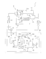
- FIG. 2 is a refrigerant circuit diagram of the refrigeration apparatus 1 according to the first embodiment.
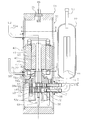
- FIG. 2 is a longitudinal sectional view of the low-stage compressor 21 of the first embodiment.
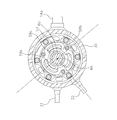
- BB sectional view of the low-stage compressor 21 of the first embodiment CC sectional view of the low-stage compressor 21 of the first embodiment
- FIG. 1 shows a refrigerant circuit configuration of the refrigerating apparatus 1 of the first embodiment.
- the refrigeration apparatus 1 of the present embodiment is an apparatus that performs a two-stage compression refrigeration cycle using carbon dioxide that is a refrigerant that operates in a supercritical region.
- the refrigerating device 1 of the present embodiment can be used for an air conditioner for cooling and heating, an air conditioner for cooling only, a chiller / heater, a refrigeration device, a freezing storage device, and the like.
- the refrigerating apparatus 1 of the present embodiment includes a multi-stage compression system 20, a four-way switching valve 5, a heat source side heat exchanger 2, a bridge circuit 3, expansion mechanisms 8, 9, a use side heat exchanger 4, an economizer. And a heat exchanger 7.
- the multi-stage compression system 20 compresses the refrigerant.
- the gas refrigerant is introduced into the first accumulator 22 at the inlet of the low-stage compressor 21 via the four-way switching valve 5 and the refrigerant pipe 13.
- the refrigerant is compressed by the low-stage compressor 21 and the high-stage compressor 23, and reaches the four-way switching valve 5 via the pipe 18.
- the four-way switching valve 5 switches the direction of the flow of the refrigerant from the multistage compression system 20 to the heat source side heat exchanger 2 or the use side heat exchanger 4.
- the refrigeration apparatus 1 is an air conditioner and performs a cooling operation
- the refrigerant flows from the four-way switching valve 5 to the heat source side heat exchanger 2 (condenser).
- the refrigerant flowing through the heat source side heat exchanger 2 (condenser) reaches the receiver 6 via the check valve 3a, the pipe 11, and the check valve 11e of the bridge circuit 3.
- the liquid refrigerant from the receiver 6 continues to flow through the pipe 11, is decompressed by the expansion mechanism 9, and goes to the use-side heat exchanger 4 (evaporator) via the check valve 3 c of the bridge circuit 3.
- the refrigerant heated by the use-side heat exchanger 4 (evaporator) is compressed again by the multi-stage compression system 20 via the four-way switching valve 5.
- the refrigerant flows from the four-way switching valve 5 to the use side heat exchanger 4 (condenser), the check valve 3b of the bridge circuit 3, the pipe 11, the receiver 6, the expansion mechanism 9, and the reverse of the bridge circuit 3. It flows in the order of the stop valve 3d, the use side heat exchanger 4 (evaporator), and the four-way switching valve 5.
- the economizer heat exchanger 7 is arranged in the refrigerant pipe 11 between the receiver 6 and the expansion mechanism 9. At the branch 11 a of the pipe 11, a part of the refrigerant branches and is reduced to an intermediate pressure by the expansion mechanism 8.
- the intermediate-pressure refrigerant is heated by the high-pressure refrigerant flowing through the pipe 11 in the economizer heat exchanger 7, and is injected via the intermediate injection pipe 12 into the intermediate-pressure merging portion 15 b of the multistage compression system 20.
- the gas component of the refrigerant flows from the receiver 6 via the pipe 19 to the intermediate injection pipe 12.
- the multistage compression system 20 of the present embodiment includes a first accumulator 22, a low stage compressor 21, an intercooler 26, A second accumulator 24, a high-stage compressor 23, an oil separator 25, an oil cooler 27, and a pressure reducer 31a are provided.
- the refrigerant compressed by the low-stage compressor 21 is further compressed by the high-stage compressor 23.
- the compressors 21 and 23 include accumulators 22 and 24, respectively.
- the accumulators 22, 24 serve to temporarily store the refrigerant before entering the compressor and prevent liquid refrigerant from being sucked into the compressor.
- the low-pressure gas refrigerant heated by the evaporator flows to the first accumulator 22 via the refrigerant pipe 13.
- the gas refrigerant in the first accumulator 22 flows to the low-stage compressor 21 via the suction pipe 14.
- the refrigerant compressed by the low-stage compressor 21 is discharged from the discharge pipe 15a, flows through the intermediate-pressure refrigerant pipes 151 to 153, and reaches the second accumulator 24.
- the intercooler 26 is arranged between the intermediate-pressure refrigerant pipes 151 and 152.
- the intercooler 26 is a heat exchanger that cools the intermediate-pressure refrigerant with, for example, outdoor air.
- the intercooler 26 may be arranged adjacent to the heat source side heat exchanger 2 and exchange heat with air by a common fan.
- the intercooler 26 increases the efficiency of the refrigeration system 1 by cooling the intermediate-pressure refrigerant.
- the intermediate pressure refrigerant is injected from the intermediate injection pipe 12 into the junction 15b of the intermediate pressure refrigerant pipe 152.
- the junction 15b of the intermediate injection pipe 12 with the pipe 152 is disposed downstream of the intercooler 26.
- the temperature of the refrigerant injected by the intermediate injection is lower than the temperature of the refrigerant flowing through the pipe 152. Therefore, the intermediate injection lowers the temperature of the refrigerant flowing through the pipe 152 and improves the efficiency of the refrigeration apparatus 1.
- the multi-stage compression system 20 of the present embodiment further includes an oil discharge pipe 32 that discharges excess oil of the low-stage compressor 21.
- the oil discharge pipe 32 connects the low-stage compressor 21 with the intermediate-pressure pipe 151.
- the oil discharge pipe 32 discharges not only the excess oil accumulated in the oil sump of the low-stage compressor but also the excess refrigerant accumulated in the oil sump.
- a connection portion of the oil discharge pipe 32 with the intermediate-pressure refrigerant pipe 151 is a portion upstream of the intercooler 26.
- the refrigerant sent to the second accumulator 24 by the pipe 153 is introduced into the high-stage compressor 23 through the suction pipe 16.
- the refrigerant is compressed in the high-stage compressor 23 to have a high pressure, and is discharged to the discharge pipe 17.
- the refrigerant discharged to the discharge pipe 17 flows to the oil separator 25.
- the oil separator 25 separates the refrigerant and the oil.
- the separated oil is returned to the low-stage compressor 21 via the oil return pipe 31.
- the multi-stage compression system 20 of the present embodiment further includes an oil discharge pipe 33 that discharges excess oil of the high-stage compressor.
- the oil discharge pipe 33 connects the high-stage compressor 23 and the discharge pipe 17 of the high-stage compressor 23.
- a pressure reducer 31a is arranged in the middle of the oil return pipe 31.
- the pressure reducer 31a is for reducing the pressure of the high-pressure oil discharged from the oil separator 25.
- a capillary tube is used as the decompressor 31a.
- An oil cooler 27 is arranged in the oil return pipe 31.
- the oil cooler 27 is a heat exchanger that cools the oil flowing through the oil return pipe 31 with, for example, outdoor air.
- the oil cooler 27 is for cooling the high-temperature oil discharged from the oil separator 25.
- the oil cooler 27 may be arranged, for example, in the vicinity of the heat source side heat exchanger 2 and exchange heat with air using a common fan.
- the oil of the present embodiment (the refrigerating machine oil), if the refrigerating machine oil used in the CO 2 refrigerant is not particularly limited, CO 2 refrigerant and incompatible oils are particularly suitable.
- the refrigerator oil include PAG (polyalkylene glycols) and POE (polyol esters).
- the refrigerating apparatus 1 of the present embodiment performs two-stage compression using two compressors. Two or more stages of compression may be performed using three or more compressors. Further, three or more stages of compression may be performed.
- the oil return pipe 31 returns the oil from the oil separator 25 to the low-stage compressor 21.
- the oil return pipe 31 may directly return the oil discharged from the high-stage compressor 23 to the low-stage compressor 21.
- the low-stage compressor 21 and the high-stage compressor 23 of the present embodiment are both two-cylinder type and oscillating rotary compressors. is there. Since the compressors 21 and 23 have almost the same configuration, a detailed description will be given using the low-stage compressor 21 here.
- FIG. 2 is a longitudinal sectional view of the low-stage compressor 21, and FIGS. 3 to 5 are horizontal sectional views at positions AA to CC in FIG. However, the components of the motor 40 are not shown in the BB cross-sectional view of FIG.
- the low-stage compressor 21 includes the container 30, the compression section 50, the motor 40, the crankshaft 60, and the terminal 35.
- Container 30 The container 30 has a substantially cylindrical shape with the rotation axis RA of the motor 40 as a central axis.
- the inside of the container is kept confidential.
- the low-stage compressor 21 maintains an intermediate pressure
- the high-stage compressor 23 maintains a high pressure.
- the lower part inside the container 30 is an oil reservoir (not shown) for storing oil (lubricating oil).
- the container 30 houses the motor 40, the crankshaft 60, and the compression unit 50 inside.
- a terminal 35 is arranged above the container 30.
- the container 30 is connected with refrigerant suction pipes 14a and 14b and a discharge pipe 15a, an oil return pipe 31, and an oil discharge pipe 32.
- the motor 40 is a brushless DC motor.
- the motor 40 generates power for rotating the crankshaft 60 about the rotation axis RA.
- the motor 40 is disposed above the compression unit 50 in the space inside the container 30 and below the upper space.
- the motor 40 has a stator 41 and a rotor 42.
- Stator 41 is fixed to the inner wall of container 30.
- the rotor 42 rotates by interacting magnetically with the stator 41.
- the stator 41 has a stator core 46 and an insulator 47.
- Stator core 46 is made of steel.
- the insulator 47 is made of resin. The insulator 47 is disposed above and below the stator core 46, and is wound.
- crankshaft 60 transmits the power of the motor 40 to the compression section 50.
- the crankshaft 60 has a main shaft portion 61, a first eccentric portion 62a, and a second eccentric portion 62b.
- the main shaft portion 61 is a portion that is concentric with the rotation axis RA.
- the main shaft 61 is fixed to the rotor 42.
- the first eccentric portion 62a and the second eccentric portion 62b are eccentric with respect to the rotation axis RA.
- the shape of the first eccentric portion 62a and the shape of the second eccentric portion 62b are symmetric with respect to the rotation axis RA.
- an oil tube 69 is provided at the lower end of the crankshaft 60.
- the oil tube 69 pumps up oil (lubricating oil) from the oil reservoir.
- the pumped lubricating oil rises in an oil passage inside the crankshaft 60 and is supplied to a sliding portion of the compression unit 50.
- the compression unit 50 is a two-cylinder compression mechanism.
- the compression section 50 includes a first cylinder 51, a first piston 56, a second cylinder 52, a second piston 66, a front head 53, a middle plate 54, a rear head 55, and front mufflers 58a and 58b.
- a first compression chamber 71 and a second compression chamber 72 are formed in the compression section 50.
- the first and second compression chambers are spaces in which a refrigerant is supplied and compressed.
- both the compressors 21 and 23 are two-cylinder type compressors. Both or one of the compressors may be a one cylinder type compressor.
- the first cylinder 51 is provided with a suction hole 14e, a discharge recess 59, a bush accommodation hole 57a, and a blade moving hole 57b.
- the first cylinder 51 houses the main shaft 61 of the crankshaft 60, the first eccentric portion 62a, and the first piston 56.
- the suction hole 14e allows the first compression chamber 71 to communicate with the inside of the suction pipe 14a.
- a pair of bushes 56c is accommodated in the bush accommodation hole 57a.
- the first piston 56 has an annular portion 56a and a blade 56b.
- the first eccentric portion 62a of the crankshaft 60 is fitted into the annular portion 56a.
- the blade 56b is sandwiched between a pair of bushes 56c.
- the first piston 56 divides the first compression chamber 71 into two. One is a low-pressure chamber 71a communicating with the suction hole 14e. The other is a high-pressure chamber 71b communicating with the discharge recess 59.
- the annular portion 56a revolves clockwise, the volume of the high-pressure chamber 71b decreases, and the refrigerant in the high-pressure chamber 71b is compressed.
- the tip of the blade 56b reciprocates between the blade moving hole 57b and the bush accommodating hole 57a.
- Front mufflers 58a and 58b are fixed to the front head 53.
- the front muffler reduces noise when the refrigerant is discharged.
- the refrigerant compressed in the first compression chamber 71 is discharged to the first front muffler space 58e between the front muffler 58a and the front head 53 via the discharge recess 59. After the refrigerant further moves to the second front muffler space 58f between the two front mufflers 58a and 58b, the refrigerant is discharged from the discharge holes 58c and 58d (see FIG. 4) provided in the front muffler 58b under the motor 40. Is blown out into the space.
- the compressed refrigerant discharged from the discharge holes 58c and 58d of the front muffler 58a moves to the upper space of the container 30 from the gap of the motor 40, is discharged from the discharge pipe 15a, and travels toward the high-stage compressor 23.
- the second compression chamber 72 includes a second cylinder 52, a second piston 66, a rear head 55, a middle This is a space surrounded by the plate 54.
- the flow of the refrigerant compressed in the second compression chamber 72 is also substantially the same as the flow of the refrigerant compressed in the first compression chamber 71, and a detailed description thereof will be omitted.
- the refrigerant compressed in the second compression chamber 72 the refrigerant is once sent to the rear muffler space 55a provided in the rear head 55, and further sent to the front muffler spaces 58e and 58f by the front mufflers 58a and 58b. What is different.
- the rotary compression section of the compressor 21 uses the first piston 56 in which the annular portion 56a and the blade 56b are integrated.
- the rotary type compression unit may use a vane instead of the blade, and may use a vane and a piston separately.
- the oil return pipe 31 is located below the motor 40 and in a space above the compression section 50, as shown in FIG. It is connected to the container 30 so that the internal flow paths communicate.
- the oil blown out from the oil return pipe 31 into the container 30 collides with the insulator 47 of the motor 40, and then falls on the front muffler 58b and the annular member 53a for fixing the front head 53. Merge with the oil pool at the lower part of the inside of 30.
- the oil return pipe 31 It is preferable to connect the oil return pipe 31 to a space above the second compression chamber 72. If the oil return pipe 31 is connected to a space lower than the second compression chamber 72, the possibility that the oil return pipe 31 will be lower than the oil level of the oil reservoir increases, and if so, forming is not preferable.
- the oil return pipe 31 may be connected to a higher part of the container 30.
- it may be connected to a core cut portion of the stator 41 of the motor 40.
- it is preferable to be connected to the lower part as close as possible to the oil reservoir, because the oil is supplied to the sliding parts (in the vicinity of the compression chambers 71 and 72) earlier.
- the inner diameter of the oil return pipe 31 is, for example, not less than 10 mm and not more than 12 mm.
- the oil discharge pipe 32 is connected to the container 30 so that the internal flow path communicates with the space above the compression unit 50 below the motor 40.
- connection position of the oil discharge pipe 32 to the container 30 is lower than the compression chamber 72, the oil may be excessively lost from the oil pool. Further, if the position is higher than the motor 40, the difference from the discharge pipe 15a becomes small, and the significance of separately providing the oil discharge pipe 32 is impaired.
- the mounting height position of the oil discharge pipe 32 to the container 30 is equal to the mounting height position of the oil return pipe 31 to the container 30. This facilitates adjustment of the oil level of the oil reservoir.
- the mounting position of the oil discharge pipe 32 to the planar container 30 is a position opposite to the discharge holes 58c and 58d of the front muffler 58b with respect to the rotation axis RA of the motor 40.
- the opposite position means a range of 180 ° other than a total of 180 °, which is 90 ° left and right with respect to the rotation axis RA from the connection position of the oil discharge pipe 32.
- a part of the discharge hole 58c is not at the opposite position, but here, half or more of the area of the discharge holes 58c and 58d means the opposite side.
- the inner diameter of the oil discharge pipe 32 is equal to the inner diameter of the oil return pipe 31.
- a pipe smaller than the inner diameter of the discharge pipe 15a is used. More specifically, the inner diameter of the oil discharge pipe 32 is, for example, 10 mm or more and 12 mm or less.
- connection position of the oil discharge pipe 32 to the container 30 is different from that of the oil return pipe 31 to the container 30.
- the position is 90 ° or more away from the connection position in the rotation direction of the motor 40 (the direction of the arrow in FIG. 5).
- the position is 180 ° or more apart. In the present embodiment, this angle is represented by ⁇ .
- Theta is greater than or equal to 270 °.
- ⁇ should be 330 ° or less.
- the height of the connection position of the oil return pipe 31 to the container 30 was equal to the height of the connection position of the oil discharge pipe 32 to the container 30.
- the height of the connection position of the oil return pipe 31 to the container 30 may be higher than the height of the connection position of the oil discharge pipe 32 to the container 30.
- a first accumulator 22 is arranged upstream of a low-stage compressor 21, and a second accumulator 24 is arranged upstream of a high-stage compressor 23.
- the accumulators 22, 24 store the flowing refrigerant once, prevent the liquid refrigerant from flowing to the compressor, and prevent liquid compression of the compressor. Since the configurations of the first accumulator 22 and the second accumulator 24 are almost the same, the first accumulator 22 will be described with reference to FIG.
- the low-pressure gas refrigerant heated by the evaporator flows through the refrigerant pipe 13 via the four-way switching valve 5 and is introduced into the accumulator 22.
- the gas refrigerant is introduced into the first and second compression chambers 71 and 72 from the suction pipes 14a and 14b of the compressor 21.
- Liquid refrigerant and oil accumulate below the inside of the accumulator.
- Small holes 14c and 14d are formed in the suction pipes 14a and 14b below the accumulator.
- the diameter of the holes 14c and 14d is, for example, 1 mm to 2 mm.
- the oil joins with the gas refrigerant through the holes 14c and 14d little by little together with the liquid refrigerant and is sent to the compression chamber.
- the multi-stage compression system 20 of the present embodiment is a system including a low-stage compressor 21, a high-stage compressor 23, intermediate-pressure refrigerant pipes 151 to 153 and 16, a pressure reduction element, and an oil discharge pipe 32.
- the intermediate-pressure refrigerant pipes 151 to 153 and 16 introduce the refrigerant compressed and discharged by the low-stage compressor 21 into the suction part of the high-stage compressor 23.
- the pressure reducing element is arranged in the middle of the refrigerant pipes 151 to 153. The pressure reducing element reduces the pressure of the refrigerant flowing through the intermediate-pressure refrigerant pipe.
- the oil discharge pipe 32 discharges excess oil or liquid refrigerant of the low-stage compressor 21.
- the oil discharge pipe 32 connects the low-stage compressor 21 and the intermediate-pressure refrigerant pipe 151 upstream of the pressure reducing element.
- the pressure reducing element is the intercooler 26, the converging portion 15b of the intermediate injection passage, or both.
- the intercooler 26 lowers the temperature and pressure of the refrigerant itself.
- the relatively low-temperature, low-pressure refrigerant flowing through the intermediate injection pipe 12 joins the refrigerant flowing through the intermediate-pressure refrigerant pipe 152, so that the pressure of the refrigerant flowing through the intermediate-pressure refrigerant pipe 152 decreases. I do.
- the oil discharge pipe 32 is connected to an intermediate pressure refrigerant pipe upstream of the pressure reducing element. Comparing the pressure of the refrigerant or oil between the intermediate-pressure refrigerant pipe 151 and the oil discharge pipe 32, the oil discharge pipe 32 discharges the relatively high-pressure refrigerant and oil compressed by the compression unit 50.
- the intermediate-pressure refrigerant pipe 151 has a difference that the refrigerant that has been slightly depressurized in the container 30 is the refrigerant discharged from the discharge pipe 15a.
- the pressure of the oil discharge pipe 32 is slightly higher than the pressure of the intermediate pressure refrigerant pipe 151 upstream of the pressure reducing element and the pressure of the oil discharge pipe 32. Therefore, the refrigerant and the oil are discharged from the oil discharge pipe 32.
- the difference between the pressure in the upstream part of the intermediate pressure refrigerant pipe 151 and the pressure in the oil discharge pipe 32 is smaller than that in the intermediate pressure refrigerant pipe 151. Therefore, the amounts of the refrigerant and oil discharged from the oil discharge pipe 32 are suppressed without becoming excessive.
- the amount of refrigerant or oil discharged is smaller than in the case where the oil discharge pipe 32 is connected downstream of the pressure reducing elements of the intermediate-pressure refrigerant pipes 152 and 153. Therefore, by connecting the oil discharge pipe 32 to the intermediate-pressure refrigerant pipe 151 upstream of the pressure reducing element, the oil amount of the low-stage compressor 21 can be appropriately controlled.
- the pressure-lowering element is the intercooler 26
- the intercooler 26 cools the refrigerant containing oil flowing from the oil discharge pipe 32.
- the temperature of the refrigerant flowing into the high-stage compressor 23 is reduced, and there is an effect of protecting the high-stage compressor from overheating.
- the oil discharge pipe 32 is connected to the container 30 above the compression chamber 72 and below the motor 40.
- the low-stage compressor 21 is a two-cylinder type compressor, and has two compression chambers, a first compression chamber 71 and a second compression chamber 72.
- the term “compression chamber” refers to the second compression chamber 72.
- the oil discharge pipe 32 is connected to a position above the compression chamber 72 of the container 30 and below the motor 40. And can be discharged from the low-stage compressor. For this reason, the control of the oil amount of the low-stage compressor can be performed more quickly.
- the end of the discharge pipe 15 a in the container 30 is arranged in a space above the motor 40 in the container 30.
- a pressure difference between the two is formed.
- the refrigerant is mainly a carbon dioxide refrigerant
- the oil is an oil incompatible with the carbon dioxide.
- oils incompatible with carbon dioxide are PAG (polyalkylene glycols) and POE (polyol esters).
- the liquid refrigerant easily collects upward, and the excess liquid refrigerant is easily discharged from the oil discharge pipe 32.
- the multi-stage compression system 20 of the present embodiment further has an oil return pipe 31.
- the oil return pipe 31 returns the oil discharged from the high-stage compressor 23 to the low-stage compressor 21.
- the multi-stage compression system 20 of the present embodiment has both the oil discharge pipe 32 and the oil return pipe 31, the oil amount of the low-stage compressor 21 can be smoothly controlled.
- the oil discharge pipe 32 is connected to the upstream of the intercooler 26 on the intermediate-pressure refrigerant pipe 151.
- the oil discharge pipe 32 is connected between the intercooler 26 and the junction 15b of the intermediate injection passage on the intermediate-pressure refrigerant pipe 152.
- the pressure difference between the oil discharge pipe 32 and the intermediate-pressure refrigerant pipe is larger in the case of Modification 1A than in the case of the first embodiment. Therefore, in the case of the modified example 1A, the oil discharge amount is larger than in the case of the first embodiment. Therefore, the modified example 1A controls the oil amount of the low-stage compressor to be smaller than that of the first embodiment.
- Other configurations and features are the same as those of the first embodiment.
- the oil discharge pipe 32 is connected to the upstream of the intercooler 26 on the intermediate-pressure refrigerant pipe 151.
- the oil discharge pipe 32 is connected in the middle of the intercooler 26.
- the pressure difference between the oil discharge pipe 32 and the pipe in the middle of the intercooler 26 is larger than the pressure difference between the oil discharge pipe 32 and the pipe 151 upstream of the intercooler 26. Therefore, in the case of the modified example 1B, the oil discharge amount is larger than in the case of the first embodiment.
- the number is smaller than in the case of the modified example 1A. Therefore, in the modified example 1B, the oil amount of the low-stage compressor is controlled to be smaller than that of the first embodiment.
- Other configurations and features are the same as those of the first embodiment.
- the multi-stage compression system 20 includes an intercooler 26 on the upstream side of the intermediate-pressure refrigerant pipe connected to the discharge pipe 15a of the low-stage compressor 21 and a junction 15b of an intermediate injection passage on the downstream side.
- the multi-stage compression system 20 of Modification 1C only the intercooler 26 is provided in the intermediate-pressure refrigerant pipe, and the merging portion 15b of the intermediate injection passage is not provided.
- Modification 1C does not include the economizer heat exchanger 7.
- Other configurations are the same as in the first embodiment.
- the oil discharge pipe 32 is connected upstream of the intercooler 26 on the intermediate-pressure refrigerant pipe 151, as in the first embodiment.
- the present disclosure is also effective when the multi-stage compression system 20 includes only the junction portion 15b of the intermediate injection passage in the intermediate-pressure refrigerant pipe and does not include the intercooler 26. .
- the multistage compression system 20 of Modification 1D also has the same features (3-1) to (3-4) as the multistage compression system 20 of the first embodiment.
- the present disclosure is also effective when the multi-stage compression system 20 includes only the economizer heat exchanger 7 in the upstream portion of the intermediate injection pipe 12 and does not include the receiver 6. is there.
- the multi-stage compression system 20 includes an intercooler 26 upstream of the intermediate-pressure refrigerant pipes 151 to 153 connected to the discharge pipe 15a of the low-stage compressor 21, and a junction 15b of the intermediate injection passage downstream.
- the multistage compression system 20 of Modification 1E includes a junction portion 15b of an intermediate injection passage on the upstream side of the intermediate-pressure refrigerant pipes 154 to 156, and an intercooler 26 on the downstream side.
- the oil discharge pipe 32 is connected to the intermediate pressure refrigerant pipe 154 upstream of the junction 15b of the intermediate injection passage.
- Other configurations are the same as those of the first embodiment.
- the multi-stage compression system 20 of Modification 1E also has the same features (3-1) to (3-4) as the multi-stage compression system 20 of the first embodiment.
- the multistage compression system 20 of Modification 1F includes a junction portion 15b of the intermediate injection passage upstream of the intermediate-pressure refrigerant pipes 154 to 156 and an intercooler 26 downstream thereof, as shown in FIG. Have.
- the oil discharge pipe 32 is connected to the intermediate pressure refrigerant pipe 154 upstream of the junction 15b of the intermediate injection passage.
- the oil discharge pipe 32 is connected between the junction portion 15b of the intermediate injection passage on the intermediate pressure refrigerant pipe 155 and the intercooler 26.
- Other configurations are the same as those of Modification Example 1E.
- the pressure difference between the oil discharge pipe 32 and the intermediate-pressure refrigerant pipe 155 between the junction part 15b and the intercooler 26 is the pressure difference between the oil discharge pipe 32 and the pipe 154 upstream of the junction part 15b. Greater than. Therefore, in the case of the modified example 1F, the oil discharge amount is larger than in the case of the modified example 1E. Therefore, the modified example 1F controls the oil amount of the low-stage compressor to be smaller than that of the modified example 1E.
- the multi-stage compression system 20 of Modification 1G includes a junction 15b of the intermediate injection passage upstream of the intermediate-pressure refrigerant pipes 154 to 156 and an intercooler 26 downstream thereof, as shown in FIG. Have.
- the oil discharge pipe 32 is connected to the intermediate pressure refrigerant pipe 154 upstream of the junction 15b of the intermediate injection passage.
- the oil discharge pipe 32 is connected in the middle of the refrigerant flow path of the intercooler 26.
- Other configurations are the same as those of Modification Example 1E.
- the pressure difference between the oil discharge pipe 32 and the middle of the refrigerant flow path of the intercooler 26 is larger than the pressure difference between the oil discharge pipe 32 and the pipe 154 upstream of the junction 15b. Therefore, in the case of the modification 1G, the amount of oil discharge is larger than in the case of the modification 1E. Therefore, the modified example 1G controls the oil amount of the low-stage compressor smaller than that of the modified example 1E.
Abstract
複数台の多段圧縮機を用いた冷凍装置においては、それぞれの圧縮機において、冷凍機油を適量に保つ必要性があった。多段圧縮システム(20)は、低段圧縮機(21)と、高段圧縮機(23)と、冷媒配管(151~156、16)と、圧力低下要素(26、15b)と、油排出管(32)とを有する。冷媒配管(151~156、16)は、低段圧縮機(21)で圧縮され、吐出された冷媒を、高段圧縮機(23)の吸入部分に導入する。圧力低下要素(26、15b)は、中間圧冷媒配管(151~156)の途中に配置されている。油排出管(32)は、低段圧縮機(21)の油を排出する。油排出管(32)は、低段圧縮機(21)と、圧力低下要素(26、15b)よりも上流側の冷媒配管と、を接続する。
Description
冷媒と油を利用する多段圧縮システム。
冷凍装置において、作動冷媒によっては、複数の圧縮機を用いた多段圧縮機構が推奨され、用いられている。複数の圧縮機を用いた多段圧縮機構においては、冷凍機油を、複数の圧縮機において、適量にコントロールすることが重要である。言い換えると、一つの圧縮機に極度に油が偏在することがないように制御する必要がある。
特許文献1(特開2008-261227号公報)では、低段側および高段側の圧縮機の油面の高さを一定の高さに保つために、低段側の圧縮機には低段側油抜き通路を、高段側で吐出された油を低段側圧縮機の吸入管に戻す油戻し通路を設けている。
特許文献1では、低段側油抜き通路を高段側のアキュムレータの下流で、高段側圧縮機の吸入側に接続している。また、インタークーラや中間インジョクションの冷媒合流点については、特に考慮されていない。しかし、低段側の冷媒吐出部から高段側の冷媒吸入部にいたる冷媒配管においては、インタークーラや中間インジョクションの冷媒合流点のような圧力低下要素を設けた場合、冷媒配管に圧力の低下が生じる。したがって、油抜き通路の接続位置によって、油抜き通路を通過する冷媒、油量が変動し、冷媒回路に大きな影響を生じる。たとえば、インタークーラを用いたシステムでは、インタークーラをバイパスする冷媒が多くなると、冷媒冷却量が不足する可能性がある。
第1観点の多段圧縮システムは、冷媒と油を利用するものである。多段圧縮システムは、低段圧縮機と、高段圧縮機と、冷媒配管と、圧力低下要素と、油排出管とを有する。低段圧縮機は、冷媒を圧縮する。高段圧縮機は、低段圧縮機で圧縮された冷媒をさらに圧縮する。冷媒配管は、低段圧縮機で圧縮され、吐出された冷媒を、高段圧縮機の吸入部分に導入する。圧力低下要素は、冷媒配管の途中に配置されている。油排出管は、低段圧縮機の油を排出する。油排出管は、低段圧縮機と、圧力低下要素よりも上流側の冷媒配管と、を接続する。
第1観点の多段圧縮システムは、油排出管が低段圧縮機と、圧力低下要素よりも上流側の冷媒配管と、が接続されているので、油排出管が排出する油量が抑制され、低段圧縮機の油量が適量に制御できる。
第2観点の多段圧縮システムは、第1観点のシステムであって、低段圧縮機は、圧縮部と、モータと、容器と、を有している。圧縮部は、ロータリー式である。圧縮部には、圧縮室が形成されている。圧縮室で、冷媒を圧縮する。モータは、圧縮部を駆動する。モータは、圧縮部よりも上に配置される。容器は、圧縮部とモータを収容する。油排出管は、容器の、モータより下、圧縮室よりも上に、接続されている。なお、低段圧縮機が高さの違う2以上の圧縮室を有するときは、ここで言う圧縮室は、最も下側の圧縮室を意味する。
第2観点の多段圧縮システムは、油排出管が、容器の圧縮室より上、モータより下の位置に接続されているため、低段圧縮機の過剰の油を過不足なく、低段圧縮機から排出することができる。
第3観点の多段圧縮システムは、第1観点又は第2観点のシステムであって、圧力低下要素は、インタークーラである。インタークーラは、低段圧縮機で吐出された冷媒を、高段圧縮機に吸入する前に冷却する。
第3観点の多段圧縮システムは、油排出管が、低段圧縮機と、インタークーラよりも上流側の冷媒配管と、が接続されているので、油排出管が排出する油量が抑制され、低段圧縮機の油量が適量に制御できる。
第4観点の多段圧縮システムは、第3観点のシステムであって、さらに、中間インジェクション通路の合流部分を有している。中間インジェクション通路の合流部分は、中間圧の冷媒を冷媒配管に注入する。中間インジェクション通路の合流部分は、インタークーラの上流側に、接続されている。油排出管は、合流部分と、インタークーラの間に接続されている。
第4観点の多段圧縮システムは、油排出管は、合流部分とインタークーラの間に接続されているので、油排出管と、冷媒配管の圧力差が適度になり、油排出管が排出する油量が適度に制御され、低段圧縮機の油量が適量に制御できる。
第5観点の多段圧縮システムは、第1観点または第2観点のシステムであって、さらに、インタークーラを有している。インタークーラは、冷媒配管の途中に接続される。インタークーラは、低段圧縮機で吐出された冷媒を、高段圧縮機に吸入する前に冷却する。圧力低下要素は、インタークーラの下流側部分である。
第5観点の多段圧縮システムは、インタークーラの途中に油排出管が接続されている。油排出量が適切に制御され、低段圧縮機の油量が適量に制御できる。
第6観点の多段圧縮システムは、第1観点または第2観点のシステムであって、圧力低下要素は、中間インジェクション通路の合流部分である。中間インジェクション通路は、中間圧の冷媒を冷媒配管に注入する。
第6観点の多段圧縮システムは、中間インジェクション通路の合流部分よりも上流側の冷媒配管に、油排出管が接続されているので、冷媒配管の圧力の低下が小さく、油排出管から排出される油の排出量が抑制され、低段圧縮機の油量が適量に制御される。
第7観点の多段圧縮システムは、第6観点のシステムであって、さらに、インタークーラを有している。インタークーラは、中間インジェクション通路の合流部分の上流側に、配置されている。インタークーラは、低段圧縮機で吐出された冷媒を、高段圧縮機に吸入する前に冷却する。油排出管は、インタークーラと合流部分との間に接続されている。
第7観点の多段圧縮システムは、油排出管が、インタークーラと合流部分との間に接続されているため、油排出量が適切に制御され、低段圧縮機の油量が適量に制御できる。
第8観点の多段圧縮システムは、第1観点~第7観点のいずれかのシステムであって、冷媒は、二酸化炭素を主とする冷媒であり、油は、二酸化炭素と非相溶の油である。
第8観点の多段圧縮システムは、冷媒と油が非相溶であるため、低段圧縮機の油たまりにおいて、冷媒と油が上下に分離しやすく、冷媒を主として、油排出管から排出しやすい。
<第1実施形態>
(1)冷凍装置1の冷媒回路
(1-1)冷凍装置1の冷媒回路全体
第1実施形態の冷凍装置1の冷媒回路構成を図1に示す。本実施形態の冷凍装置1は、超臨界域で作動する冷媒である二酸化炭素を用い、二段圧縮式の冷凍サイクルを行う装置である。本実施形態の冷凍装置1は、冷暖房を行う空気調和装置、冷房専用の空気調和装置、冷温水器、冷蔵装置、冷凍貯蔵装置などに用いることができる。
(1)冷凍装置1の冷媒回路
(1-1)冷凍装置1の冷媒回路全体
第1実施形態の冷凍装置1の冷媒回路構成を図1に示す。本実施形態の冷凍装置1は、超臨界域で作動する冷媒である二酸化炭素を用い、二段圧縮式の冷凍サイクルを行う装置である。本実施形態の冷凍装置1は、冷暖房を行う空気調和装置、冷房専用の空気調和装置、冷温水器、冷蔵装置、冷凍貯蔵装置などに用いることができる。
本実施形態の冷凍装置1は、多段圧縮システム20と、四方切換弁5と、熱源側熱交換器2と、ブリッジ回路3と、膨張機構8、9と、利用側熱交換器4と、エコノマイザ熱交換器7とを有している。
多段圧縮システム20は、冷媒を圧縮する。ガス冷媒は、四方切換弁5、冷媒配管13を経由して、低段圧縮機21の入口の第1アキュムレータ22に導入される。冷媒は、低段圧縮機21、高段圧縮機23により圧縮され、配管18を経由して、四方切換弁5にいたる。
四方切換弁5は、多段圧縮システム20よりの冷媒を、熱源側熱交換器2と利用側熱交換器4のいずれの方向に流すかを切り換える。たとえば、冷凍装置1が空気調和装置であり、冷房運転のときは、冷媒は、四方切換弁5から熱源側熱交換器2(凝縮器)に流れる。熱源側熱交換器2(凝縮器)を流れた冷媒は、ブリッジ回路3の逆止弁3a、配管11、逆止弁11eを経由して、レシーバ6に達する。レシーバ6より液冷媒は、引き続き配管11を流れ、膨張機構9で減圧され、ブリッジ回路3の逆止弁3cを経由して、利用側熱交換器4(蒸発器)へ向かう。利用側熱交換器4(蒸発器)で加熱された冷媒は、四方切換弁5を経由して、再び多段圧縮システム20で圧縮される。一方、暖房運転時は、冷媒は、四方切換弁5から利用側熱交換器4(凝縮器)、ブリッジ回路3の逆止弁3b、配管11、レシーバ6、膨張機構9、ブリッジ回路3の逆止弁3d、利用側熱交換器4(蒸発器)、四方切換弁5の順に流れる。
エコノマイザ熱交換器7は、冷媒配管11の途中、レシーバ6と、膨張機構9の間に配置されている。配管11の分岐11aにて、一部の冷媒は分岐して、膨張機構8にて中間圧に減圧される。中間圧の冷媒は、エコノマイザ熱交換器7において、配管11を流れる高圧冷媒によって加熱され、中間インジェクション配管12を経由して、多段圧縮システム20の中間圧の合流部分15bにインジェクションされる。また、レシーバ6より冷媒のガス成分が配管19を経由して、中間インジェクション配管12に合流する。
(1-2)多段圧縮システム20における冷媒および油の流れ
本実施形態の多段圧縮システム20は、図1に示すように、第1アキュムレータ22と、低段圧縮機21と、インタークーラ26と、第2アキュムレータ24と、高段圧縮機23と、油分離器25と、オイルクーラ27と、減圧器31aとを備えている。
本実施形態の多段圧縮システム20は、図1に示すように、第1アキュムレータ22と、低段圧縮機21と、インタークーラ26と、第2アキュムレータ24と、高段圧縮機23と、油分離器25と、オイルクーラ27と、減圧器31aとを備えている。
本実施形態においては、低段圧縮機21で圧縮された冷媒を、さらに、高段圧縮機23で圧縮する。圧縮機21、23は、それぞれ、アキュムレータ22、24を備えている。アキュムレータ22、24は、圧縮機に入る前の冷媒を一度蓄えて、液冷媒が圧縮機に吸入されないようにする役割を担う。
次に、本実施形態の多段圧縮システム20における冷媒、油の流れを、図1を利用して説明する。
本実施形態においては、蒸発器(利用側熱交換器4または熱源側熱交換器2)で加熱された低圧のガス冷媒は、冷媒配管13を経由して、第1アキュムレータ22に流れる。第1アキュムレータ22のガス冷媒は、吸入管14を経由して、低段圧縮機21へと流れる。低段圧縮機21で圧縮された冷媒は、吐出管15aより吐出され、中間圧冷媒配管151~153を流れ、第2アキュムレータ24に達する。
インタークーラ26は、中間圧冷媒配管151、152の間に配置されている。インタークーラ26は、中間圧の冷媒を、たとえば、室外の空気で冷却する熱交換器である。インタークーラ26は、熱源側熱交換器2と隣接して配置して、共通のファンで空気と熱交換しても良い。インタークーラ26は、中間圧の冷媒を冷却することにより、冷凍装置1の効率を高める。
また、中間圧冷媒配管152の合流部分15bには、中間インジェクション配管12より、中間圧の冷媒がインジェクションされる。本実施形態においては、中間インジェクション配管12の配管152への合流部分15bは、インタークーラ26の下流側に配置される。中間インジェクションでインジェクションされる冷媒は、配管152を流れる冷媒よりも温度が低い。したがって、中間インジェクションは、配管152を流れる冷媒の温度を低下させ、冷凍装置1の効率を向上させる。
本実施形態の多段圧縮システム20は、さらに、低段圧縮機21の過剰の油を排出する油排出管32を備えている。油排出管32は、低段圧縮機21と、中間圧の配管151を接続する。油排出管32は、低段圧縮機の油溜まりに溜まった過剰の油のみならず油溜まりに溜まった過剰の冷媒も排出する。油排出管32の中間圧冷媒配管151との接続部分は、インタークーラ26よりも上流部分である。
配管153により第2アキュムレータ24に送られた冷媒は、吸入管16より、高段圧縮機23に導入される。冷媒は、高段圧縮機23において、圧縮されて、高圧となり、吐出管17に吐出される。
吐出管17に吐出された冷媒は、油分離器25に流れる。油分離器25は、冷媒と油を分離する。分離された油は、油戻し管31を経由して、低段圧縮機21に戻される。
本実施形態の多段圧縮システム20は、さらに、高段圧縮機の過剰の油を排出する油排出管33を備えている。油排出管33は、高段圧縮機23と、高段圧縮機23の吐出管17とを接続する。
油戻し管31の途中には、減圧器31aが配置されている。減圧器31aは、油分離器25より排出された高圧の油の減圧をするためのものである。減圧器31aは、具体的には、たとえば、キャピラリーチューブが用いられる。
油戻し管31の途中には、オイルクーラ27が配置されている。オイルクーラ27は、油戻し管31を流れる油を、たとえば、室外の空気で冷却する熱交換器である。オイルクーラ27は、油分離器25より排出された高温の油を冷却するためのものである。オイルクーラ27は、たとえば、熱源側熱交換器2の近傍に配置し、共通のファンで空気と熱交換しても良い。
なお、本実施形態の油(冷凍機油)は、CO2冷媒で用いられる冷凍機油であれば、特に限定されないが、CO2冷媒と非相溶の油が特に適している。冷凍機油の例としては、PAG(ポリアルキレングリコール類)、POE(ポリオールエステル類)などがある。
なお、本実施形態の冷凍装置1は2台の圧縮機で二段の圧縮を行っている。3台以上の圧縮機を用いて、二段以上の圧縮を行ってもよい。また、三段以上の圧縮を行っても良い。
なお、本実施形態においては、油戻し管31は、油分離器25からの油を低段圧縮機21に戻している。油戻し管31は、高段圧縮機23から排出された油を直接低段圧縮機21に戻してもよい。
(2)圧縮機と圧縮機に接続される配管、装置の構成
本実施形態の低段圧縮機21、高段圧縮機23は、ともに、2シリンダタイプ、かつ、揺動式のロータリー圧縮機である。圧縮機21、23はほとんど同一の構成なので、ここでは、低段圧縮機21を用いて、詳細に説明する。
本実施形態の低段圧縮機21、高段圧縮機23は、ともに、2シリンダタイプ、かつ、揺動式のロータリー圧縮機である。圧縮機21、23はほとんど同一の構成なので、ここでは、低段圧縮機21を用いて、詳細に説明する。
図2は、低段圧縮機21の縦断面図、図3~5は、図2のそれぞれAA~CCの位置での水平断面図である。ただし、図4のBB断面図において、モータ40の部品は記載されていない。
低段圧縮機21は、容器30と、圧縮部50と、モータ40と、クランクシャフト60と、ターミナル35と、を有している。
(2-1)容器30
容器30は、モータ40の回転軸RAを中心軸として、略円筒状の形状である。容器の内部は機密性が保たれており、運転時に、低段圧縮機21においては中間圧、高段圧縮機23においては高圧の圧力が保持される。容器30の内部の下部は、油(潤滑油)を貯留するための油溜まり(図示せず)となっている。
容器30は、モータ40の回転軸RAを中心軸として、略円筒状の形状である。容器の内部は機密性が保たれており、運転時に、低段圧縮機21においては中間圧、高段圧縮機23においては高圧の圧力が保持される。容器30の内部の下部は、油(潤滑油)を貯留するための油溜まり(図示せず)となっている。
容器30は、内部に、モータ40と、クランクシャフト60と、圧縮部50とを収容している。容器30の上部には、ターミナル35が配置されている。また、容器30には、冷媒の吸入管14a、14bおよび吐出管15aと、油戻し管31と、油排出管32とが接続されている。
(2-2)モータ40
モータ40は、ブラシレスDCモータである。モータ40は、クランクシャフト60を、回転軸RAを中心に回転する動力を発生する。モータ40は、容器30の内部の空間内で、上部の空間の下、圧縮部50の上に配置されている。モータ40は、ステータ41およびロータ42を有する。ステータ41は、容器30の内壁に固定されている。ロータ42は、ステータ41と磁気的な相互作用をすることによって回転する。
モータ40は、ブラシレスDCモータである。モータ40は、クランクシャフト60を、回転軸RAを中心に回転する動力を発生する。モータ40は、容器30の内部の空間内で、上部の空間の下、圧縮部50の上に配置されている。モータ40は、ステータ41およびロータ42を有する。ステータ41は、容器30の内壁に固定されている。ロータ42は、ステータ41と磁気的な相互作用をすることによって回転する。
ステータ41は、ステータコア46と、インシュレータ47とを有する。ステータコア46は、鋼製である。インシュレータ47は、樹脂製である。インシュレータ47は、ステータコア46の上下に配置され、巻線が巻かれている。
(2-3)クランクシャフト60
クランクシャフト60は、モータ40の動力を圧縮部50に伝達する。クランクシャフト60は、主軸部61、第1偏心部62a、第2偏心部62bを有する。
クランクシャフト60は、モータ40の動力を圧縮部50に伝達する。クランクシャフト60は、主軸部61、第1偏心部62a、第2偏心部62bを有する。
主軸部61は、回転軸RAと同心である部位である。主軸部61は、ロータ42に固定されている。
第1偏心部62aおよび第2偏心部62bは、回転軸RAに対して偏心している。第1偏心部62aの形状および第2偏心部62bの形状は、回転軸RAを基準として互いに対称である。
クランクシャフト60の下端には、オイルチューブ69が設けられている。オイルチューブ69は、油溜まりから油(潤滑油)をくみ上げる。くみ上げられた潤滑油は、クランクシャフト60の内部の油通路を上昇し、圧縮部50の摺動箇所に供給される。
(2-4)圧縮部50
圧縮部50は、2シリンダ型の圧縮機構である。圧縮部50は、第1シリンダ51、第1ピストン56、第2シリンダ52、第2ピストン66、フロントヘッド53、ミドルプレート54、リアヘッド55、フロントマフラ58a、58bを有する。
圧縮部50は、2シリンダ型の圧縮機構である。圧縮部50は、第1シリンダ51、第1ピストン56、第2シリンダ52、第2ピストン66、フロントヘッド53、ミドルプレート54、リアヘッド55、フロントマフラ58a、58bを有する。
圧縮部50には、第1圧縮室71、第2圧縮室72が形成されている。第1、第2圧縮室は、冷媒が供給され、圧縮される空間である。
なお、第1実施形態の多段圧縮システム20においては、圧縮機21、23はともに2シリンダタイプの圧縮機である。両方ともあるいは一方の圧縮機は、1シリンダタイプの圧縮機であってもよい。
(2-4-1)第1圧縮室71と、第1圧縮室71で圧縮される冷媒の流れ
第1圧縮室71は、図2または5に示すように、第1シリンダ51と、第1ピストン56と、フロントヘッド53と、ミドルプレート54とによって囲まれた空間である。
第1圧縮室71は、図2または5に示すように、第1シリンダ51と、第1ピストン56と、フロントヘッド53と、ミドルプレート54とによって囲まれた空間である。
第1シリンダ51には、図5に示すように、吸入孔14e、吐出凹部59、ブッシュ収容穴57a、ブレード移動穴57bが設けられている。第1シリンダ51は、クランクシャフト60の主軸61および第1偏心部62aと、第1ピストン56とを収容する。吸入孔14eは、第1圧縮室71と吸入管14aの内部とを連通させる。ブッシュ収容穴57aには、1対のブッシュ56cが収容される。
第1ピストン56は、円環部56aとブレード56bを有する。円環部56aにはクランクシャフト60の第1偏心部62aが嵌め込まれる。ブレード56bは、1対のブッシュ56cに挟まれている。第1ピストン56は、第1圧縮室71を2つに分割する。1つは、吸入孔14eに連通する低圧室71aである。もう1つは、吐出凹部59に連通する高圧室71bである。図5において、円環部56aは時計回りに公転し、高圧室71bの容積は小さくなり、高圧室71bの冷媒は圧縮される。円環部56aの公転に際し、ブレード56bの先端は、ブレード移動穴57bの側とブッシュ収容穴57aの側を往復する。
フロントヘッド53は、図2に示すように、環状部材53aによって、容器30の内側に固定されている。
フロントヘッド53には、フロントマフラ58a、58bが固定されている。フロントマフラは、冷媒が吐出される際の騒音を低減する。
第1圧縮室71で圧縮された冷媒は、吐出凹部59を経由して、フロントマフラ58aとフロントヘッド53との間の第1フロントマフラ空間58eに吐き出される。冷媒は、さらに、2つのフロントマフラ58a、58bの間の第2フロントマフラ空間58fに移動した後で、フロントマフラ58bに設けられた吐出穴58c、58d(図4参照)より、モータ40の下の空間に吹出される。
圧縮され、フロントマフラ58aの吐出穴58c、58dより吹出された冷媒は、モータ40の隙間より、容器30の上部空間に移動し、吐出管15aより吹出され、高段圧縮機23へと向かう。
(2-4-2)第2圧縮室72と、第2圧縮室72で圧縮される冷媒の流れ
第2圧縮室72は、第2シリンダ52と、第2ピストン66と、リアヘッド55と、ミドルプレート54とによって囲まれた空間である。
第2圧縮室72は、第2シリンダ52と、第2ピストン66と、リアヘッド55と、ミドルプレート54とによって囲まれた空間である。
第2圧縮室72にて圧縮される冷媒の流れも、ほぼ第1圧縮室71にて圧縮される冷媒の流れと同様なので、詳細な説明は省略する。ただし、第2圧縮室72で圧縮された冷媒の場合は、いったん、リアヘッド55に設けられたリアマフラ空間55aに送られた後で、さらに、フロントマフラ58a、58bによるフロントマフラ空間58e、58fに送られるところが、異なる。
なお、第1実施形態の多段圧縮システム20においては、圧縮機21のロータリー式圧縮部は、円環部56aとブレード56bとが一体となった、第1ピストン56を用いている。ロータリー式圧縮部は、ブレードの代わりにベーンを用い、ベーンとピストンが別体となったものを用いてもよい。
(2-5)圧縮機と、油戻し管31と油排出管32の接続位置について
油戻し管31は、図2に示すように、モータ40の下で、圧縮部50の上の空間に、内部流路が連通するように、容器30に接続されている。油戻し管31から、容器30の内部に吹出された油は、モータ40のインシュレータ47に衝突した後で、フロントマフラ58bや、フロントヘッド53を固定する環状部材53aの上に落ち、さらに、容器30内部下部の油溜まりに合流する。
油戻し管31は、図2に示すように、モータ40の下で、圧縮部50の上の空間に、内部流路が連通するように、容器30に接続されている。油戻し管31から、容器30の内部に吹出された油は、モータ40のインシュレータ47に衝突した後で、フロントマフラ58bや、フロントヘッド53を固定する環状部材53aの上に落ち、さらに、容器30内部下部の油溜まりに合流する。
油戻し管31を、第2圧縮室72よりも上の空間に接続するのが好ましい。油戻し管31を第2圧縮室72よりも下の空間に接続すると、油溜まりの油面よりも下になる可能性が高くなり、そうなると、フォーミングを生じるので好ましくない。
また、油戻し管31は、容器30のより上部に接続しても良い。たとえば、モータ40のステータ41のコアカットの部分に接続されていても良い。ただし、油溜まりになるべく近い低部に接続される方が、より早く、摺動部(圧縮室71、72付近)に油を供給することにつながり、好ましい。
また、油戻し管31の内径は、たとえば、10mm以上12mm以下である。
油排出管32は、図2に示すように、モータ40の下で、圧縮部50の上の空間に、内部流路が連通するように、容器30に接続されている。
油排出管32の容器30への接続位置が圧縮室72よりも低くなると、油が過剰に油溜まりより失われるおそれがある。また、モータ40よりも高い位置になると、吐出管15aと差が小さくなり、油排出管32を別途設ける意義が損なわれる。
また、本実施形態では、図2に示すように、油排出管32の容器30への取り付け高さ位置は、油戻し管31の容器30への取り付け高さ位置と同等である。これによって、油溜まりの油面の高さ調整が容易になる。
また、図4に示すように、油排出管32の平面的な容器30への取り付け位置は、モータ40の回転軸RAに対して、フロントマフラ58bの吐出穴58c、58dの反対の位置である。ここで、反対の位置とは、油排出管32の接続位置から回転軸RAに対して左右に90°ずつの合計180°以外の180°の範囲との意味である。なお、図4では、吐出穴58cの一部が反対の位置ではないが、ここでは、吐出穴58c、58dの面積の半分以上が反対側との意味である。
本実施形態では、油排出管32の容器30への接続位置が、フロントマフラ58bの吐出穴58c、58dの位置から離れているので、フロントマフラ58bの吐出穴58c、58dから吐出した冷媒を、直接油排出管32によって、低段圧縮機21より排出するのを低減できる。
油排出管32の内径は、油戻し管31の内径と同等である。吐出管15aの内径よりも細いものを用いる。より具体的には、油排出管32の内径は、たとえば、10mm以上12mm以下である。
また、図5に示すように、油排出管32と油戻し管31の平面的な位置関係を見れば、油排出管32の容器30への接続位置は、油戻し管31の容器30への接続位置から、モータ40の回転方向(図5の矢印の方向)に90°以上離れた位置である。好ましくは、180°以上はなれた位置である。本実施形態では、この角度は、θであらわされている。シータは、270°以上である。また、θは、330°以下にはすべきである。
本実施形態では、油排出管32と油戻し管31の位置が十分離されているため、油戻し管31で低段圧縮機21の容器30内に導入した油がそのまま油排出管32により、容器30外に排出されるのを低減し、低段圧縮機21の均油を容易に実現することができる。
なお、第1実施形態の多段圧縮システム20においては、油戻し管31の容器30への接続位置の高さは、油排出管32の容器30への接続位置の高さと同等であった。油戻し管31の容器30への接続位置の高さは、油排出管32の容器30への接続位置の高さよりも高くてもよい。
(2-6)アキュムレータ22
本実施形態の多段圧縮システム20においては、低段圧縮機21の上流に第1アキュムレータ22が、高段圧縮機23の上流に第2アキュムレータ24が配置されている。アキュムレータ22、24は、流れてきた冷媒を一度蓄えて、液冷媒が圧縮機に流れるのを防止し、圧縮機の液圧縮を防止する。第1アキュムレータ22と第2アキュムレータ24の構成はほとんど同じなので、第1アキュムレータ22について、図2を用いて説明する。
本実施形態の多段圧縮システム20においては、低段圧縮機21の上流に第1アキュムレータ22が、高段圧縮機23の上流に第2アキュムレータ24が配置されている。アキュムレータ22、24は、流れてきた冷媒を一度蓄えて、液冷媒が圧縮機に流れるのを防止し、圧縮機の液圧縮を防止する。第1アキュムレータ22と第2アキュムレータ24の構成はほとんど同じなので、第1アキュムレータ22について、図2を用いて説明する。
蒸発器で加熱された低圧のガス冷媒が、四方切換弁5を経由して、冷媒配管13を流れ、アキュムレータ22に導入される。ガス冷媒は、圧縮機21の吸入管14a、14bより、第1、第2圧縮室71、72に導入される。アキュムレータの内部下方には、液冷媒、油が溜まる。吸入管14a、14bには、アキュムレータ内部の下方において、小さな穴14c、14dが形成されている。穴14c、14dの径は、たとえば、1mm~2mmである。油は、液冷媒とともに、少量ずつ穴14c、14dを経由して、ガス冷媒に合流して、圧縮室へ送られる。
(3)特徴
(3-1)
本実施形態の多段圧縮システム20は、低段圧縮機21と、高段圧縮機23と、中間圧冷媒配管151~153、16と、圧力低下要素と、油排出管32とを有するシステムである。中間圧冷媒配管151~153、16は、低段圧縮機21で圧縮され、吐出された冷媒を、高段圧縮機23の吸入部分に導入する。圧力低下要素は、冷媒配管151~153の途中に配置されている。圧力低下要素は、中間圧冷媒配管を流れる冷媒の圧力を低下させる。油排出管32は、低段圧縮機21の過剰の油または液冷媒を排出する。油排出管32は、低段圧縮機21と、圧力低下要素よりも上流側の中間圧冷媒配管151と、を接続する。
(3-1)
本実施形態の多段圧縮システム20は、低段圧縮機21と、高段圧縮機23と、中間圧冷媒配管151~153、16と、圧力低下要素と、油排出管32とを有するシステムである。中間圧冷媒配管151~153、16は、低段圧縮機21で圧縮され、吐出された冷媒を、高段圧縮機23の吸入部分に導入する。圧力低下要素は、冷媒配管151~153の途中に配置されている。圧力低下要素は、中間圧冷媒配管を流れる冷媒の圧力を低下させる。油排出管32は、低段圧縮機21の過剰の油または液冷媒を排出する。油排出管32は、低段圧縮機21と、圧力低下要素よりも上流側の中間圧冷媒配管151と、を接続する。
本実施形態においては、圧力低下要素は、インタークーラ26、または、中間インジェクション通路の合流部分15b、またはその両方である。インタークーラ26は、冷媒自体の温度と圧力を低下させる。中間インジェクション通路の合流部分15bにおいては、中間インジェクション配管12を流れる比較的低温、低圧の冷媒が、中間圧冷媒配管152を流れる冷媒に合流するため、中間圧冷媒配管152を流れる冷媒の圧力が低下する。
本実施形態の多段圧縮システム20は、中間圧冷媒配管の、圧力低下要素よりも上流部分に、油排出管32が接続されている。中間圧冷媒配管151と、油排出管32において、冷媒または油の圧力を比較すると、油排出管32は、圧縮部50で圧縮された比較的高圧の冷媒、油が吐出されているのに対して、中間圧冷媒配管151には、容器30内で若干減圧された後の冷媒が吐出管15aより吐出された冷媒であるという差異がある。言い換えると、中間圧冷媒配管151の圧力低下要素より上流部の圧力と油排出管32の圧力は、油排出管32の圧力の方が若干高い。したがって、油排出管32から、冷媒や油が排出されるのである。
とは言っても、中間圧冷媒配管151の圧力低下要素より上流部の圧力と油排出管32の圧力の差は小さい。そこで、油排出管32より吐出される冷媒や油の量は過度にならず抑制されている。特に、油排出管32を、中間圧冷媒配管152、153の圧力低下要素より下流部に接続する場合に比べて、冷媒または油排出量は少ない。したがって、油排出管32を、圧力低下要素よりも上流側の中間圧冷媒配管151に接続することにより、低段圧縮機21の油量を適正に制御できる。
また、圧力低下要素がインタークーラ26である場合、インタークーラ26の上流に油排出管32が接続されると、インタークーラ26は、油排出管32より流入した油を含む冷媒を冷却する。結果的に、高段圧縮機23に流入する冷媒の温度を低下させ、高段圧縮機の過熱保護の効果がある。
(3-2)
本実施形態の多段圧縮システム20においては、油排出管32は、圧縮室72よりも上、モータ40よりも下の前記容器30に接続されている。なお、本実施形態においては、低段圧縮機21は2シリンダタイプの圧縮機であり、圧縮室は、第1圧縮室71と第2圧縮室72の2つがある。このような場合に圧縮室と言う場合には、第2圧縮室72を指すこととする。
本実施形態の多段圧縮システム20においては、油排出管32は、圧縮室72よりも上、モータ40よりも下の前記容器30に接続されている。なお、本実施形態においては、低段圧縮機21は2シリンダタイプの圧縮機であり、圧縮室は、第1圧縮室71と第2圧縮室72の2つがある。このような場合に圧縮室と言う場合には、第2圧縮室72を指すこととする。
本実施形態の多段圧縮システム20は、油排出管32が、容器30の圧縮室72より上、モータ40より下の位置に接続されているため、低段圧縮機21の過剰の油を過不足なく、低段圧縮機から排出することができる。このため、低段圧縮機の油量の制御をより迅速に行うことができる。
また、本実施形態の多段圧縮システム20においては、図2に示すように、吐出管15aの容器30内の端部は、容器30内のモータ40の上の空間に配置されている。このように、吐出管15aと、油排出管32の配置が異なることにより、両者の内部の圧力差が形成される。
(3-3)
本実施形態の多段圧縮システム20は、冷媒は、二酸化炭素を主とする冷媒であり、油は、二酸化炭素と非相溶の油である。二酸化炭素と非相溶の油の例としては、PAG(ポリアルキレングリコール類)、POE(ポリオールエステル類)である。
本実施形態の多段圧縮システム20は、冷媒は、二酸化炭素を主とする冷媒であり、油は、二酸化炭素と非相溶の油である。二酸化炭素と非相溶の油の例としては、PAG(ポリアルキレングリコール類)、POE(ポリオールエステル類)である。
このような非相溶な油と、二酸化炭素冷媒との混合液では、冷凍装置1を通常の温度条件(-20℃以上)で運転するとき、比重の関係で、油が下で、冷媒が上になる。
そうすると、低段圧縮機21の油溜まりにおいて、液冷媒が上方に集まりやすく、油排出管32での余分な液冷媒の排出が容易になる。
(3-4)
本実施形態の多段圧縮システム20は、さらに、油戻し管31を有している。油戻し管31は、高段圧縮機23で排出された油を、低段圧縮機21に戻す。
本実施形態の多段圧縮システム20は、さらに、油戻し管31を有している。油戻し管31は、高段圧縮機23で排出された油を、低段圧縮機21に戻す。
本実施形態の多段圧縮システム20は、油排出管32と油戻し管31とを両方とも有しているため、低段圧縮機21の油量の制御を円滑に行うことができる。
(4)変形例
(4-1)変形例1A
第1実施形態の多段圧縮システム20において、油排出管32は、中間圧冷媒配管151上のインタークーラ26の上流に接続されていた。変形例1Aにおいては、油排出管32は、中間圧冷媒配管152上の、インタークーラ26と中間インジェクション通路の合流部分15bとの間に接続されている。合流部分において、油排出管32と中間圧冷媒配管の圧力差は、変形例1Aの場合、第1実施形態の場合よりも大きくなる。よって、変形例1Aの場合は、第1実施形態の場合よりも、油排出量は増大する。したがって、変形例1Aは、第1実施形態よりも低段圧縮機の油量を少なめに制御する。その他の構成と特徴は、第1実施形態と同様である。
(4-2)変形例1B
第1実施形態の多段圧縮システム20において、油排出管32は、中間圧冷媒配管151上のインタークーラ26の上流に接続されていた。変形例1Bにおいては、油排出管32は、インタークーラ26の途中に接続されている。接続部分において、油排出管32とインタークーラ26の途中の配管との圧力差は、油排出管32とインタークーラ26の上流の配管151との圧力差より大きい。よって、変形例1Bの場合は、第1実施形態の場合よりも、油排出量は増大する。ただし、変形例1Aの場合よりは、少ない。したがって、変形例1Bは、第1実施形態よりも低段圧縮機の油量を少なめに制御する。その他の構成と特徴は、第1実施形態と同様である。
第1実施形態の多段圧縮システム20において、油排出管32は、中間圧冷媒配管151上のインタークーラ26の上流に接続されていた。変形例1Bにおいては、油排出管32は、インタークーラ26の途中に接続されている。接続部分において、油排出管32とインタークーラ26の途中の配管との圧力差は、油排出管32とインタークーラ26の上流の配管151との圧力差より大きい。よって、変形例1Bの場合は、第1実施形態の場合よりも、油排出量は増大する。ただし、変形例1Aの場合よりは、少ない。したがって、変形例1Bは、第1実施形態よりも低段圧縮機の油量を少なめに制御する。その他の構成と特徴は、第1実施形態と同様である。
(4-3)変形例1C
第1実施形態の多段圧縮システム20は、低段圧縮機21の吐出管15aに繋がる中間圧冷媒配管の上流側にインタークーラ26、下流側に中間インジェクション通路の合流部分15bを備えていた。変形例1Cの多段圧縮システム20においては、中間圧冷媒配管にインタークーラ26を備えているのみで、中間インジェクション通路の合流部分15bは備えていない。変形例1Cは、エコノマイザ熱交換器7を備えていない。その他の構成は、第1実施形態と同様である。油排出管32は、第1実施形態と同様に、中間圧冷媒配管151上のインタークーラ26の上流に接続されている。
第1実施形態の多段圧縮システム20は、低段圧縮機21の吐出管15aに繋がる中間圧冷媒配管の上流側にインタークーラ26、下流側に中間インジェクション通路の合流部分15bを備えていた。変形例1Cの多段圧縮システム20においては、中間圧冷媒配管にインタークーラ26を備えているのみで、中間インジェクション通路の合流部分15bは備えていない。変形例1Cは、エコノマイザ熱交換器7を備えていない。その他の構成は、第1実施形態と同様である。油排出管32は、第1実施形態と同様に、中間圧冷媒配管151上のインタークーラ26の上流に接続されている。
また、変形例1Cとは逆に、多段圧縮システム20は、中間圧冷媒配管に中間インジェクション通路の合流部分15bを備えているのみで、インタークーラ26は備えていない場合も本開示は有効である。
(4-4)変形例1D
第1実施形態の多段圧縮システム20は中間インジェクション配管の上流部分に、レシーバ6およびエコノマイザ熱交換器7を配していた。変形例1Dの多段圧縮システム20においては、中間インジェクション配管12の上流部分に、レシーバ6を備えているのみで、エコノマイザ熱交換器7は備えていない。その他の構成は、第1実施形態と同様である。
第1実施形態の多段圧縮システム20は中間インジェクション配管の上流部分に、レシーバ6およびエコノマイザ熱交換器7を配していた。変形例1Dの多段圧縮システム20においては、中間インジェクション配管12の上流部分に、レシーバ6を備えているのみで、エコノマイザ熱交換器7は備えていない。その他の構成は、第1実施形態と同様である。
変形例1Dの多段圧縮システム20も、第1実施形態の多段圧縮システム20と同様の特徴(3-1)~(3-4)を有する。
また、変形例1Dとは逆に、多段圧縮システム20は、中間インジェクション配管12の上流部分に、エコノマイザ熱交換器7を備えているのみで、レシーバ6は備えていない場合も本開示は有効である。
(4-5)変形例1E
第1実施形態の多段圧縮システム20は、低段圧縮機21の吐出管15aに繋がる中間圧冷媒配管151~153の上流側にインタークーラ26、下流側に中間インジェクション通路の合流部分15bを備えていた。変形例1Eの多段圧縮システム20は、図6に示すように、中間圧冷媒配管154~156の上流側に中間インジェクション通路の合流部分15b、下流側にインタークーラ26を備えている。油排出管32は、中間圧冷媒配管154上の中間インジェクション通路の合流部分15bの上流に接続されている。その他の構成は、第1実施形態と同じである。
第1実施形態の多段圧縮システム20は、低段圧縮機21の吐出管15aに繋がる中間圧冷媒配管151~153の上流側にインタークーラ26、下流側に中間インジェクション通路の合流部分15bを備えていた。変形例1Eの多段圧縮システム20は、図6に示すように、中間圧冷媒配管154~156の上流側に中間インジェクション通路の合流部分15b、下流側にインタークーラ26を備えている。油排出管32は、中間圧冷媒配管154上の中間インジェクション通路の合流部分15bの上流に接続されている。その他の構成は、第1実施形態と同じである。
変形例1Eの多段圧縮システム20も、第1実施形態の多段圧縮システム20と同様の特徴(3-1)~(3-4)を有する。
(4-6)変形例1F
変形例1Fの多段圧縮システム20は、変形例1Eと同様に、図6に示すように、中間圧冷媒配管154~156の上流側に中間インジェクション通路の合流部分15b、下流側にインタークーラ26を備えている。変形例1Eでは、油排出管32は、中間圧冷媒配管154上の中間インジェクション通路の合流部分15bの上流に接続されている。変形例1Fでは、油排出管32は、中間圧冷媒配管155上の中間インジェクション通路の合流部分15bと、インタークーラ26との間に接続されている。その他の構成は、変形例1Eと同じである。
変形例1Fの多段圧縮システム20は、変形例1Eと同様に、図6に示すように、中間圧冷媒配管154~156の上流側に中間インジェクション通路の合流部分15b、下流側にインタークーラ26を備えている。変形例1Eでは、油排出管32は、中間圧冷媒配管154上の中間インジェクション通路の合流部分15bの上流に接続されている。変形例1Fでは、油排出管32は、中間圧冷媒配管155上の中間インジェクション通路の合流部分15bと、インタークーラ26との間に接続されている。その他の構成は、変形例1Eと同じである。
接続部分において、油排出管32と、合流部分15bとインタークーラ26との間の中間圧冷媒配管155との圧力差は、油排出管32と、合流部分15bの上流の配管154との圧力差より大きい。よって、変形例1Fの場合は、変形例1Eの場合よりも、油排出量は増大する。したがって、変形例1Fは、変形例1Eよりも低段圧縮機の油量を少なめに制御する。
(4-7)変形例1G
変形例1Gの多段圧縮システム20は、変形例1Eと同様に、図6に示すように、中間圧冷媒配管154~156の上流側に中間インジェクション通路の合流部分15b、下流側にインタークーラ26を備えている。変形例1Eでは、油排出管32は、中間圧冷媒配管154上の中間インジェクション通路の合流部分15bの上流に接続されている。変形例1Gでは、油排出管32は、インタークーラ26の冷媒流路の途中に接続されている。その他の構成は、変形例1Eと同じである。
変形例1Gの多段圧縮システム20は、変形例1Eと同様に、図6に示すように、中間圧冷媒配管154~156の上流側に中間インジェクション通路の合流部分15b、下流側にインタークーラ26を備えている。変形例1Eでは、油排出管32は、中間圧冷媒配管154上の中間インジェクション通路の合流部分15bの上流に接続されている。変形例1Gでは、油排出管32は、インタークーラ26の冷媒流路の途中に接続されている。その他の構成は、変形例1Eと同じである。
接続部分において、油排出管32と、インタークーラ26の冷媒流路の途中との圧力差は、油排出管32と、合流部分15bの上流の配管154との圧力差より大きい。よって、変形例1Gの場合は、変形例1Eの場合よりも、油排出量は増大する。したがって、変形例1Gは、変形例1Eよりも低段圧縮機の油量を少なめに制御する。
以上、本開示の実施形態を説明したが、特許請求の範囲に記載された本開示の趣旨及び範囲から逸脱することなく、形態や詳細の多様な変更が可能なことが理解されるであろう。
1 冷凍装置
2 熱源側熱交換器
3 ブリッジ回路
4 利用側熱交換器
5 四方切換弁
6 レシーバ
7 エコノマイザ熱交換器
8、9 膨張機構
12 中間インジェクション配管
151~156、16 中間圧冷媒配管
15b 中間インジェクション通路の合流部分
20 多段圧縮システム
21 低段圧縮機
22 第1アキュムレータ
23 高段圧縮機
24 第2アキュムレータ
25 油分離器
26 インタークーラ
30 容器
31 油戻し管
31a 減圧器
32 油排出管
40 モータ
50 圧縮部
71 第1圧縮室
72 第2圧縮室
58a、58b マフラ
58c、58d 吐出穴
2 熱源側熱交換器
3 ブリッジ回路
4 利用側熱交換器
5 四方切換弁
6 レシーバ
7 エコノマイザ熱交換器
8、9 膨張機構
12 中間インジェクション配管
151~156、16 中間圧冷媒配管
15b 中間インジェクション通路の合流部分
20 多段圧縮システム
21 低段圧縮機
22 第1アキュムレータ
23 高段圧縮機
24 第2アキュムレータ
25 油分離器
26 インタークーラ
30 容器
31 油戻し管
31a 減圧器
32 油排出管
40 モータ
50 圧縮部
71 第1圧縮室
72 第2圧縮室
58a、58b マフラ
58c、58d 吐出穴
Claims (8)
- 冷媒と油とを利用する多段圧縮システム(20)であって、
前記冷媒を圧縮する低段圧縮機(21)と、
前記低段圧縮機で圧縮された前記冷媒をさらに圧縮する高段圧縮機(23)と、
前記低段圧縮機で圧縮され、吐出された冷媒を、前記高段圧縮機の吸入部分に導入する冷媒配管(151~156、16)と、
前記冷媒配管の途中に配置された圧力低下要素(26、15b)と、
前記低段圧縮機の油を排出する油排出管であって、前記低段圧縮機と、前記圧力低下要素よりも上流側の前記冷媒配管と、を接続する油排出管(32)と、
を備えた、
多段圧縮システム。 - 前記低段圧縮機は、
ロータリー式であって、前記冷媒を圧縮する圧縮室を形成された圧縮部(50)と、
前記圧縮部を駆動するモータであって、前記圧縮部よりも上に配置されるモータ(40)と、
前記圧縮部と前記モータを収容する容器(30)と、
を有し、
前記油排出管は、前記容器の前記モータより下かつ前記圧縮室よりも上に接続されている、
請求項1に記載の多段圧縮システム。 - 前記圧力低下要素は、
前記低段圧縮機で吐出された冷媒を、前記高段圧縮機に吸入する前に冷却するインタークーラ(26)である、
請求項1または2に記載の多段圧縮システム。 - 前記多段圧縮システムは、さらに、
前記インタークーラ(26)の上流側に、中間圧の前記冷媒を前記冷媒配管に注入する中間インジェクション通路の合流部分(15b)を有し、
前記油排出管は、前記合流部分と、前記インタークーラの間に接続されている、
請求項3に記載の多段圧縮システム。 - 前記多段圧縮システムは、さらに、
前記冷媒配管の途中に接続され、前記低段圧縮機で吐出された冷媒を、前記高段圧縮機に吸入する前に冷却するインタークーラを有し、
前記圧力低下要素は、前記インタークーラの下流側部分である、
請求項1または2に記載の多段圧縮システム。 - 前記圧力低下要素は、
中間圧の前記冷媒を前記冷媒配管に注入する中間インジェクション通路の合流部分である、
請求項1または2に記載の多段圧縮システム。 - 前記多段圧縮システムは、さらに、
前記合流部分の上流側に、前記低段圧縮機で吐出された冷媒を、前記高段圧縮機に吸入する前に冷却するインタークーラを有し、
前記油排出管は、前記インタークーラと前記合流部分との間に接続されている、
請求項6に記載の多段圧縮システム。 - 前記冷媒は、二酸化炭素を主成分とする冷媒であり、
前記油は、二酸化炭素と非相溶な油である、
請求項1~7のいずれか1項に記載の多段圧縮システム。
Priority Applications (3)
| Application Number | Priority Date | Filing Date | Title |
|---|---|---|---|
| CN201980063259.1A CN112752934B (zh) | 2018-09-28 | 2019-09-25 | 多级压缩系统 |
| US17/280,089 US11415342B2 (en) | 2018-09-28 | 2019-09-25 | Multistage compression system |
| EP19867267.7A EP3859234A4 (en) | 2018-09-28 | 2019-09-25 | MULTI-STAGE COMPRESSION SYSTEM |
Applications Claiming Priority (4)
| Application Number | Priority Date | Filing Date | Title |
|---|---|---|---|
| JP2018-185073 | 2018-09-28 | ||
| JP2018185073A JP6773095B2 (ja) | 2018-09-28 | 2018-09-28 | 多段圧縮システム |
| JP2018-233788 | 2018-12-13 | ||
| JP2018233788A JP6702401B1 (ja) | 2018-12-13 | 2018-12-13 | 多段圧縮システム |
Publications (1)
| Publication Number | Publication Date |
|---|---|
| WO2020067196A1 true WO2020067196A1 (ja) | 2020-04-02 |
Family
ID=69949611
Family Applications (1)
| Application Number | Title | Priority Date | Filing Date |
|---|---|---|---|
| PCT/JP2019/037671 WO2020067196A1 (ja) | 2018-09-28 | 2019-09-25 | 多段圧縮システム |
Country Status (4)
| Country | Link |
|---|---|
| US (1) | US11415342B2 (ja) |
| EP (1) | EP3859234A4 (ja) |
| CN (1) | CN112752934B (ja) |
| WO (1) | WO2020067196A1 (ja) |
Cited By (1)
| Publication number | Priority date | Publication date | Assignee | Title |
|---|---|---|---|---|
| JP7125637B1 (ja) * | 2021-03-16 | 2022-08-25 | ダイキン工業株式会社 | 圧縮装置及び冷凍装置 |
Families Citing this family (1)
| Publication number | Priority date | Publication date | Assignee | Title |
|---|---|---|---|---|
| CN117639384A (zh) * | 2024-01-26 | 2024-03-01 | 山东天瑞重工有限公司 | 一种双级磁悬浮透平真空泵的自冷却系统及方法 |
Citations (4)
| Publication number | Priority date | Publication date | Assignee | Title |
|---|---|---|---|---|
| JPH04371759A (ja) * | 1991-06-21 | 1992-12-24 | Hitachi Ltd | 二段圧縮二段膨張式の冷凍サイクル |
| JP2008261227A (ja) | 2007-04-10 | 2008-10-30 | Daikin Ind Ltd | 圧縮装置 |
| JP2012180963A (ja) * | 2011-03-01 | 2012-09-20 | Denso Corp | 冷凍サイクル |
| JP2013181736A (ja) * | 2012-03-05 | 2013-09-12 | Daikin Industries Ltd | コンテナ用冷凍装置 |
Family Cites Families (34)
| Publication number | Priority date | Publication date | Assignee | Title |
|---|---|---|---|---|
| US3360127A (en) * | 1964-11-23 | 1967-12-26 | C P Wood And Company | Oil separator for refrigeration systems |
| US3719057A (en) * | 1971-10-08 | 1973-03-06 | Vilter Manufacturing Corp | Two-stage refrigeration system having crankcase pressure regulation in high stage compressor |
| US3848422A (en) * | 1972-04-27 | 1974-11-19 | Svenska Rotor Maskiner Ab | Refrigeration plants |
| US4151724A (en) * | 1977-06-13 | 1979-05-01 | Frick Company | Pressurized refrigerant feed with recirculation for compound compression refrigeration systems |
| US4660384A (en) * | 1986-04-25 | 1987-04-28 | Vilter Manufacturing, Inc. | Defrost apparatus for refrigeration system and method of operating same |
| US5236311A (en) | 1992-01-09 | 1993-08-17 | Tecumseh Products Company | Compressor device for controlling oil level in two-stage high dome compressor |
| JPH07260263A (ja) | 1994-03-17 | 1995-10-13 | Sanyo Electric Co Ltd | 二段圧縮冷凍装置 |
| JPH07301465A (ja) | 1994-05-02 | 1995-11-14 | Mitsubishi Heavy Ind Ltd | 二段圧縮式冷凍装置 |
| JP3903409B2 (ja) | 2000-03-29 | 2007-04-11 | 三菱電機株式会社 | 二段圧縮冷凍機 |
| JP4455546B2 (ja) | 2001-03-13 | 2010-04-21 | 三菱電機株式会社 | 高圧シェルタイプ圧縮機及び冷凍装置 |
| JP4158102B2 (ja) | 2003-03-19 | 2008-10-01 | 三菱電機株式会社 | 多段圧縮装置 |
| JP2004353996A (ja) | 2003-05-30 | 2004-12-16 | Daikin Ind Ltd | 冷凍装置 |
| JP2005211449A (ja) | 2004-01-30 | 2005-08-11 | Samii Kk | 遊技機 |
| WO2006025530A1 (ja) | 2004-09-02 | 2006-03-09 | Daikin Industries, Ltd. | 冷凍装置 |
| JP3861913B1 (ja) | 2004-09-02 | 2006-12-27 | ダイキン工業株式会社 | 冷凍装置 |
| JP2006258002A (ja) | 2005-03-17 | 2006-09-28 | Toshiba Kyaria Kk | 密閉形圧縮機 |
| JPWO2007000815A1 (ja) | 2005-06-29 | 2009-01-22 | 株式会社前川製作所 | 二段スクリュー圧縮機の給油方法、装置及び冷凍装置の運転方法 |
| JP2006348951A (ja) | 2006-09-29 | 2006-12-28 | Sanyo Electric Co Ltd | 圧縮機 |
| CN100425839C (zh) * | 2006-11-15 | 2008-10-15 | 烟台冰轮股份有限公司 | 单机双级螺杆制冷压缩机组及其应用方法 |
| JP5110882B2 (ja) * | 2007-01-05 | 2012-12-26 | 株式会社日立産機システム | 無給油式スクリュー圧縮機 |
| JP4595943B2 (ja) | 2007-01-16 | 2010-12-08 | 三菱電機株式会社 | 圧縮機 |
| JP4814167B2 (ja) | 2007-07-25 | 2011-11-16 | 三菱重工業株式会社 | 多段圧縮機 |
| JP5017037B2 (ja) | 2007-09-26 | 2012-09-05 | 三洋電機株式会社 | 冷凍サイクル装置 |
| JP5029326B2 (ja) * | 2007-11-30 | 2012-09-19 | ダイキン工業株式会社 | 冷凍装置 |
| JP5109628B2 (ja) | 2007-11-30 | 2012-12-26 | ダイキン工業株式会社 | 冷凍装置 |
| JP5181813B2 (ja) * | 2008-05-02 | 2013-04-10 | ダイキン工業株式会社 | 冷凍装置 |
| JP2011202817A (ja) | 2010-03-24 | 2011-10-13 | Toshiba Carrier Corp | 冷凍サイクル装置 |
| JP2011214758A (ja) | 2010-03-31 | 2011-10-27 | Daikin Industries Ltd | 冷凍装置 |
| CN201811498U (zh) * | 2010-09-29 | 2011-04-27 | 中原工学院 | 一种双热源型多级压缩式高温热泵 |
| JP2015034536A (ja) | 2013-08-09 | 2015-02-19 | ダイキン工業株式会社 | 圧縮機 |
| DE102013014543A1 (de) | 2013-09-03 | 2015-03-05 | Stiebel Eltron Gmbh & Co. Kg | Wärmepumpenvorrichtung |
| JP6301101B2 (ja) | 2013-10-18 | 2018-03-28 | 三菱重工サーマルシステムズ株式会社 | 2段圧縮サイクル |
| JP6594707B2 (ja) | 2015-08-27 | 2019-10-23 | 三菱重工サーマルシステムズ株式会社 | 2段圧縮冷凍システム |
| JP2018031263A (ja) | 2016-08-22 | 2018-03-01 | 日立ジョンソンコントロールズ空調株式会社 | ロータリ圧縮機 |
-
2019
- 2019-09-25 EP EP19867267.7A patent/EP3859234A4/en active Pending
- 2019-09-25 WO PCT/JP2019/037671 patent/WO2020067196A1/ja unknown
- 2019-09-25 US US17/280,089 patent/US11415342B2/en active Active
- 2019-09-25 CN CN201980063259.1A patent/CN112752934B/zh active Active
Patent Citations (4)
| Publication number | Priority date | Publication date | Assignee | Title |
|---|---|---|---|---|
| JPH04371759A (ja) * | 1991-06-21 | 1992-12-24 | Hitachi Ltd | 二段圧縮二段膨張式の冷凍サイクル |
| JP2008261227A (ja) | 2007-04-10 | 2008-10-30 | Daikin Ind Ltd | 圧縮装置 |
| JP2012180963A (ja) * | 2011-03-01 | 2012-09-20 | Denso Corp | 冷凍サイクル |
| JP2013181736A (ja) * | 2012-03-05 | 2013-09-12 | Daikin Industries Ltd | コンテナ用冷凍装置 |
Non-Patent Citations (1)
| Title |
|---|
| See also references of EP3859234A4 |
Cited By (4)
| Publication number | Priority date | Publication date | Assignee | Title |
|---|---|---|---|---|
| JP7125637B1 (ja) * | 2021-03-16 | 2022-08-25 | ダイキン工業株式会社 | 圧縮装置及び冷凍装置 |
| WO2022196370A1 (ja) * | 2021-03-16 | 2022-09-22 | ダイキン工業株式会社 | 圧縮装置及び冷凍装置 |
| CN116670396A (zh) * | 2021-03-16 | 2023-08-29 | 大金工业株式会社 | 压缩装置及制冷装置 |
| CN116670396B (zh) * | 2021-03-16 | 2023-11-28 | 大金工业株式会社 | 压缩装置及制冷装置 |
Also Published As
| Publication number | Publication date |
|---|---|
| CN112752934A (zh) | 2021-05-04 |
| US20210310702A1 (en) | 2021-10-07 |
| EP3859234A1 (en) | 2021-08-04 |
| EP3859234A4 (en) | 2021-11-03 |
| CN112752934B (zh) | 2022-03-01 |
| US11415342B2 (en) | 2022-08-16 |
Similar Documents
| Publication | Publication Date | Title |
|---|---|---|
| CN107676260B (zh) | 压缩机和包括压缩机的系统 | |
| US20110232325A1 (en) | Refrigerating apparatus | |
| US20080232992A1 (en) | Fluid Machine | |
| JP2008163894A (ja) | 多段圧縮機 | |
| WO2001022008A1 (fr) | Dispositif de refrigeration par compression a allure multiple | |
| JP2001091071A (ja) | 多段圧縮冷凍装置 | |
| WO2020067195A1 (ja) | 多段圧縮システム | |
| WO2020067194A1 (ja) | 多段圧縮システム | |
| WO2020067196A1 (ja) | 多段圧縮システム | |
| US7418833B2 (en) | Refrigeration Apparatus | |
| JP4114337B2 (ja) | 冷凍装置 | |
| JP6769472B2 (ja) | 多段圧縮システム | |
| JP6702401B1 (ja) | 多段圧縮システム | |
| JP6791233B2 (ja) | 多段圧縮システム | |
| JP6702400B1 (ja) | 多段圧縮システム | |
| JP6791234B2 (ja) | 多段圧縮システム | |
| JPH05133368A (ja) | 逆止弁装置を備えた2段圧縮冷凍装置 | |
| WO2020067197A1 (ja) | 多段圧縮システム | |
| JP3847493B2 (ja) | 二段圧縮冷凍冷蔵装置 | |
| JP2015209797A (ja) | 油冷式多段スクリュ圧縮機及びその排油方法 | |
| JP2001263838A (ja) | 多段圧縮冷凍装置 | |
| JP2001091072A (ja) | 多段圧縮冷凍装置 |
Legal Events
| Date | Code | Title | Description |
|---|---|---|---|
| 121 | Ep: the epo has been informed by wipo that ep was designated in this application |
Ref document number: 19867267 Country of ref document: EP Kind code of ref document: A1 |
|
| NENP | Non-entry into the national phase |
Ref country code: DE |
|
| ENP | Entry into the national phase |
Ref document number: 2019867267 Country of ref document: EP Effective date: 20210428 |