WO2020044444A1 - 揚程延長式工事用エレベーター - Google Patents
揚程延長式工事用エレベーター Download PDFInfo
- Publication number
- WO2020044444A1 WO2020044444A1 PCT/JP2018/031808 JP2018031808W WO2020044444A1 WO 2020044444 A1 WO2020044444 A1 WO 2020044444A1 JP 2018031808 W JP2018031808 W JP 2018031808W WO 2020044444 A1 WO2020044444 A1 WO 2020044444A1
- Authority
- WO
- WIPO (PCT)
- Prior art keywords
- rope
- direction change
- machine room
- room unit
- hoistway
- Prior art date
- Legal status (The legal status is an assumption and is not a legal conclusion. Google has not performed a legal analysis and makes no representation as to the accuracy of the status listed.)
- Ceased
Links
Images


Classifications
-
- B—PERFORMING OPERATIONS; TRANSPORTING
- B66—HOISTING; LIFTING; HAULING
- B66B—ELEVATORS; ESCALATORS OR MOVING WALKWAYS
- B66B9/00—Kinds or types of lifts in, or associated with, buildings or other structures
- B66B9/16—Mobile or transportable lifts specially adapted to be shifted from one part of a building or other structure to another part or to another building or structure
- B66B9/187—Mobile or transportable lifts specially adapted to be shifted from one part of a building or other structure to another part or to another building or structure with a liftway specially adapted for temporary connection to a building or other structure
Definitions
- the present invention relates to a lift-extended construction elevator.
- Patent Document 1 discloses a lift-extension type construction elevator.
- the lift extension type construction elevator is an elevator in which a car's ascending and descending steps are sequentially extended in accordance with the progress of construction work.
- a lift-extended construction elevator a machine room unit equipped with a hoist is lifted in a hoistway to extend a car's hoisting stroke. According to such an elevator, workers and materials for construction work can be efficiently transported.
- twists occur on the elevator ropes. If tension is applied in a state where excessive twist has occurred in the rope, kink may occur. In order to prevent this, it is necessary to cancel the twist of the rope before applying the load of the elevating body to the rope.
- a method that can eliminate the twist of the rope is, for example, to rotate the end of the unwound rope. However, the rotation of the rope cannot be transmitted beyond the sheave of the hoist.
- the rope in Patent Literature 1 is wound around a lifting wheel of a counterweight located at the lower part of the hoistway, a sheave of a hoist, and a hanging wheel of a car connected to the machine room unit, and then the machine room unit. Connected to. In this case, since most of the rope is located between the hoist and the rope drum, the above method cannot eliminate the twist of the rope.
- An object of the present invention is to provide a lift-extension type construction elevator capable of eliminating the twist of a rope.
- a lift extension type construction elevator is capable of moving up and down a hoistway, a machine room unit equipped with a hoist, and a first machine liftable up and down the hoistway and capable of supporting a load by the machine room unit.
- a lifting / lowering body, and a second lifting / lowering body capable of supporting a load at a lower portion of the hoistway, and a rope pulled out from a rope drum mounted on the machine room unit is provided with a first lifting / lowering body. After being wrapped around the body hoisting wheel, it is wrapped around the sheave of the hoisting machine, wound around the sheave of the hoisting machine, and then wrapped around the hoisting wheel of the second elevating body. It is connected to the machine room unit after being wound around a hanging wheel.
- the rope unreeled from the rope drum mounted on the machine room unit is wound around the hoist of the first elevating body, and then wound on the sheave of the hoist, and After being wrapped around the sheave, it is wrapped around the hanging wheel of the second elevating body. After being wound around the hanging wheel of the second elevating body, it is connected to the machine room unit. For this reason, the twist of the rope of the lift extension type construction elevator can be eliminated.
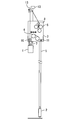
- FIG. 2 is a schematic diagram showing a first example of a lift extension type construction elevator according to the first embodiment.
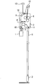
- FIG. 5 is a schematic diagram showing a second example of the lift extension type construction elevator according to the first embodiment.
- FIG. 5 is a schematic diagram showing a third example of a lift extension type construction elevator according to the first embodiment.
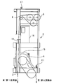
- FIG. 2 is a front view illustrating a structural example of a machine room unit according to Embodiment 1.
- FIG. 4 is a front view showing another example of the structure of the machine room unit according to Embodiment 1.
- FIG. 1 is a schematic diagram showing a first example of a lift-extended construction elevator according to the first embodiment.
- Fig. 1 shows the inside of a hoistway (not shown) of a building under construction.
- the lift extension type construction elevator includes a first elevating body 1, a second elevating body 2, a machine room unit 3, and a hoist.
- a plurality of ropes 5 are wound around the sheave 4 of the hoist.
- the first lifting body 1 is one of an elevator car and a counterweight.
- the second lifting body 2 is the other of the elevator car and the counterweight.
- FIG. 1 illustrates a case where the first lifting body 1 is a car and the second lifting body 2 is a counterweight.
- the first elevating body 1 can move up and down the hoistway along a pair of car guide rails (not shown).
- the second elevating body 2 can move up and down the hoistway along a pair of counterweight guide rails (not shown).
- the load of the second lifting body 2 can be supported at the lower part of the hoistway.
- the second lifting body 2 may be mounted on, for example, a shock absorber provided in a pit.
- the second elevating body 2 may be fixed to, for example, a car guide rail or a counterweight guide rail.
- the second elevating body 2 may be fixed to, for example, a structure on the building side under construction.
- the machine room unit 3 can move up and down the hoistway along at least one of the car guide rail and the counterweight guide rail, for example.
- the machine room unit 3 can be fixed to, for example, a car guide rail, a counterweight guide rail, or a structure on the building side under construction.
- the machine room unit 3 includes, for example, a hoist, a control panel (not shown), and a plurality of rope drums 6.
- the machine room unit 3 is provided with, for example, two or more direction change devices.
- FIG. 1 shows a case where a first direction change pulley 8 and a second direction change pulley 9 are provided as direction change devices.
- a pulley is illustrated as a turning device. However, if the rope 5 can turn and the rope 5 can smoothly slide on the turning device, the turning device has a pulley structure. It does not have to be.
- the number of rope drums 6 corresponds to the number of ropes 5 used for the elevator. For example, when six ropes 5 are used for an elevator, six rope drums 6 are mounted on the machine room unit 3. Each rope drum 6 is wound in advance with a rope 5 having a length that can correspond to the ascent / descent process in a state where the building is completed.
- the machine room unit 3 is provided with, for example, a coupling device 7 and a rope gripping device 10.
- the connecting device 7 and the rope gripping device 10 are installed, for example, at a position overlapping the first elevating body 1 when viewed from above and below.
- the connecting device 7 and the rope gripping device 10 are installed, for example, near the car guide rail or near the counterweight guide rail in the horizontal direction.
- the connecting device 7 can suspend the first elevating body 1.
- the connection device 7 is a device having a lifting function, such as a chain block or a winch. In a state where the first elevating body 1 is suspended by the connecting device 7, the load of the first elevating body 1 is supported by the machine room unit 3. In a state where the first elevating body 1 is connected to the machine room unit 3, the position of the center of gravity of the entire machine room unit 3 is closer to the first elevating body 1 than before the connection due to the influence of the mass of the first elevating body 1. Stop by.
- the rope gripping device 10 can grip the rope 5 so as to be sandwiched, for example.
- the rope gripping device 10 can simultaneously grip at least the same number of ropes 5 as the number of the rope drums 6.
- the direction change device is provided, for example, above the hoisting machine.
- the direction changing device is fixed to, for example, the framework of the machine room unit 3.
- the first direction change pulley 8 is provided, for example, near the rope drum 6 and first receives the rope 5 fed from the rope drum 6.
- the first direction change pulley 8 may be arranged anywhere in the upper, lower, left and right directions with respect to the rope drum 6.
- FIG. 1 shows a case where the first direction change pulley 8 is disposed above the rope drum 6.
- the role of the first direction change pulley 8 is to control the amount of movement of the rope 5 reciprocating in the axial direction of the rope drum 6 when the rope 5 is discharged from the rope drum 6 while changing the direction of the rope 5. By controlling the rope 5 nearby, the rope 5 is guided so as not to interfere with other devices.
- the second direction change pulley 9 is, for example, installed at a position overlapping with the first elevating body 1 when viewed from above and below.
- the second direction change pulley 9 is installed, for example, in the horizontal direction in the vicinity of a pair of car guide rails or in the vicinity of a pair of counterweight guide rails.
- the role of the second direction change pulley 9 is to determine the position at which the rope 5 is lowered vertically toward the suspension wheel of the first elevating body 1 while changing the direction of the rope 5.
- the second direction change pulley 9 is mainly arranged above the suspension wheel of the first lifting / lowering body 1. When the second direction change pulley 9 can also serve as the first direction change pulley 8, the first direction change pulley 8 need not be provided.
- Each rope 5 unreeled from the plurality of rope drums 6, for example, is first wound around a direction changing device.
- Each rope 5 is, for example, wound around the first direction change pulley 8 and then wound around the second direction change pulley 9.
- Each rope 5 is, for example, wound around a second direction change pulley 9 and then passed through a rope gripping device 10.
- Each of the ropes 5 is, for example, wound around a hanging wheel of the first elevating body 1 after being passed through the rope gripping device 10.
- Each rope 5 is wound around the sheave 4 of the hoist, for example, after being wound around the hanging wheel of the first elevating body 1.
- Each rope 5 is, for example, wound around a sheave 4 of a hoist, and then wound around a suspension wheel of the second elevating body 2.
- Each rope 5 is connected to the machine room unit 3, for example, after being wound around a hanging wheel of the second elevating body 2.
- each rope 5 is connected to the machine room unit 3 by an individual shackle, for example.
- the shackle-side rope terminal 11 is located, for example, at the lower end of the machine room unit 3.
- the rope gripping device 10 can grip the rope 5 located between the rope drum 6 and the suspension wheel of the first lifting / lowering body 1.
- the load of the first lifting / lowering body 1 and the second lifting / lowering body 2 is applied to the rope 5.
- the hoist is driven in this state, the first elevating body 1 and the second elevating body 2 move in a range below the machine room unit 3 in the building under construction. This range is the current ascent / descent stroke of the first elevating body 1 and the second elevating body 2.
- the hoist is controlled by, for example, a control panel mounted on the machine room unit 3. As the construction work progresses, the lifting process of the first lifting and lowering body 1 and the second lifting and lowering body 2 is extended.
- the load of the first elevating body 1 is supported by the machine room unit 3 via the connecting device 7.
- the load of the second hoisting body 2 is supported at the lower part of the hoistway. That is, the extension of the up-and-down stroke is performed in a state where the load of the first up-and-down body 1 and the second up-and-down body 2 is not applied to the rope 5. Extension of the lifting process is performed by lifting the machine room unit 3 and the first lifting / lowering body 1 using the lifting device 12 in a state where the rope 5 is not gripped by the rope gripping device 10.
- the lifting device 12 is, for example, a tower crane or a winch.
- the lifting of the machine room unit 3 and the first lifting / lowering body 1 needs to be performed in a state where the hanging cable of the lifting device 12 has grasped the position of the center of gravity of the lifting target for safety of work.
- the center of gravity of the machine room unit 3 is shifted toward the first lifting body 1, and therefore, the suspension cable of the lifting device 12 is provided, for example, near the upper side of the first lifting body 1. Connect to the hanging base.
- Twisting may occur in the rope 5 fed from the rope drum 6. If the shackle-side rope terminal 11 is rotated in a state where the load of the first elevating body 1 and the second elevating body 2 is not applied to the rope 5, the range from the shackle-side rope terminal 11 to the sheave 4 of the hoisting machine is obtained. The twist of the rope 5 located at the position is canceled. Since most of the rope 5 unreeled from the rope drum 6 is located between the shackle-side rope terminal 11 and the sheave 4 of the hoist, by rotating the shackle-side rope terminal 11, the twist of the rope 5 is reduced. It is fully resolved.
- FIG. 2 is a schematic diagram showing a second example of the lift-extended construction elevator according to the first embodiment.
- a third direction change pulley 13 which is a direction change device is provided.
- the third direction change pulley 13 can be moved to a place other than the machine room unit 3.
- the third direction change pulley 13 is guided by, for example, at least one of a car guide rail and a counterweight guide rail.
- the third direction change pulley 13 can be fixed to at least one of the machine room unit 3 and a structure in the hoistway.
- the structures in the hoistway include, for example, a car guide rail, a counterweight guide rail, and a structure on the building side under construction. If the third direction change pulley 13 can also serve as the second direction change pulley 9, the second direction change pulley 9 need not be provided.
- the role of the third direction change pulley 13 is to pull the rope 5 from the rope drum 6 in advance by raising the third direction change pulley 13 before the machine room unit 3 is raised while changing the direction of the rope 5. It is to be able to do the work of pulling out.
- each rope 5 is, for example, wound around the first direction change pulley 8 and then wound around the third direction change pulley 13.
- Each rope 5 is, for example, wound around a third direction change pulley 13 and then passed through a rope gripping device 10.
- the order in which the rope 5 is wound around the hoist of the first hoisting body 1, the sheave 4 of the hoisting machine, and the hoisting wheel of the second hoisting body 2 after being wound around the direction change device is shown in FIG. This is the same as the example shown.
- the positional relationship between the first directional change pulley 8 and the third directional change pulley 13 in the depth direction of FIG. 2 is set so that the rope 5 does not contact the suspension cable of the lifting device 12.
- a pulley is illustrated as a direction change device that can move the hoistway freely in the height direction and can be fixed to at least one of the machine room unit 3 and at least one of the structures in the hoistway. If the rope 5 can turn and the rope 5 can slide smoothly on the turning device, the turning device may not have a pulley structure.
- FIG. 3 is a schematic diagram showing a third example of the lift-extended construction elevator according to the first embodiment.
- FIG. 3 the example shown in FIG. 3 will be described focusing on differences from the example shown in FIG. 1 or FIG.
- the machine room unit 3 includes, in addition to the second direction change pulley 9 and the third direction change pulley 13, a fourth direction change pulley 14 as a direction change device for guiding the route of the rope 5.
- a pulley is illustrated as a direction change device for guiding the route of the rope 5, but the rope 5 can change direction and the rope 5 can smoothly slide on the direction change device. If so, the direction change device need not be a pulley structure.
- the role of the fourth direction change pulley 14 is to dispose the third direction change pulley 13 at a position closer to the center of the second elevating body 2 than the center of the first elevating body 1 in the horizontal direction.
- the space above the first elevating body 1 among the space above the machine room unit 3 can be ensured, so that the third direction change pulley 13 and the rope 5 and the lift are lifted. Interference with the hanging cable of the device 12 can be reliably avoided.
- the fourth direction change pulley 14 is fixed to, for example, the framework of the machine room unit 3.
- the fourth direction change pulley 14 is provided such that the rope 5 between the third direction change pulley 13 and the second direction change pulley 9 passes through.
- the fourth direction change pulley 14 is provided, for example, on the second lifting / lowering body 2 side with respect to the suspension cable of the lifting device 12.
- FIG. 3 illustrates a case where the first direction change pulley 8 is not provided.
- each rope 5 fed from the plurality of rope drums 6 is wound around the third direction change pulley 13 and then wound around the fourth direction change pulley 14, for example.
- Each rope 5 is, for example, wound around the fourth diverting pulley 14 and then wrapped around the second diverting pulley 9.
- Each rope 5 is, for example, wound around a second direction change pulley 9 and then passed through a rope gripping device 10.
- Each of the ropes 5 is, for example, wound around a hanging wheel of the first elevating body 1 after being passed through the rope gripping device 10.
- Each rope 5 is wound around the sheave 4 of the hoist, for example, after being wound around the hanging wheel of the first elevating body 1.
- Each rope 5 is, for example, wound around a sheave 4 of a hoist, and then wound around a suspension wheel of the second elevating body 2.
- Each rope 5 is connected to the machine room unit 3, for example, after being wound around a hanging wheel of the second elevating body 2.
- FIG. 4 is a front view showing a structural example of the machine room unit according to the first embodiment.
- FIG. 4 shows an example of the structure of the machine room unit 3 of the lift extension type construction elevator shown in FIG.
- a direction change device and six rope drums 6 are arranged at the upper part of the machine room unit 3.
- the three rope drums 6 (not shown) are arranged at the back of each of the three rope drums 6 shown.
- a hoisting machine 15 and a shackle-side rope terminal 11 are arranged below the machine room unit 3.
- a rope gripping device 10 and a control panel 16 are arranged at an intermediate portion in the vertical direction of the machine room unit 3.
- the control panel 16 is electrically connected to, for example, the hoisting machine 15 and a car device (not shown).
- the machine room unit 3 is not provided with the first direction change pulley 8 of the direction change device.
- Each rope 5 drawn out from the plurality of rope drums 6 is first wound around the second direction change pulley 9. After each rope 5 is wound around the second direction change pulley 9, the rope 5 travels through the rope holding device 10 to the suspension wheel of the first elevating body 1.
- a lifting hoist 17 is provided at the upper end of the machine room unit 3.
- the installation position of the lifting hoist 17 is arranged near the upper part of the first lifting body 1 in order to correspond to a position close to the center of gravity of the machine room unit 3 in a state where the first lifting body 1 is connected.
- the hoisting line of the lifting device 12 is connected to the lifting hoist 17.
- FIG. 5 is a front view showing another example of the structure of the machine room unit according to the first embodiment.
- FIG. 5 shows an example of the structure of the machine room unit 3 of the lift extension type construction elevator shown in FIG.
- the example shown in FIG. 5 will be described focusing on differences from the example shown in FIG.
- a first direction change pulley 8, a second direction change pulley 9, a third direction change pulley 13, and a fourth direction change pulley 14 are arranged above the machine room unit 3.
- the third direction change pulley 13 can be fixed to both the machine room unit 3 and the guide rail for the second elevating body 2.
- the first direction change pulley 8 is installed near the rope drum 6.
- the third diverting pulley 13 is arranged at the same height as or higher than the first diverting pulley 8.
- the fourth diverting pulley 14 is arranged at the same height as or lower than the first diverting pulley 8.
- the second direction change pulley 9 is installed near the space between the pair of first elevating body 1 guide rails.
- the second diverting pulley 9 is arranged at the same height as or lower than the first diverting pulley 8.
- each rope 5 unreeled from the plurality of rope drums 6 is wound around the first direction change pulley 8 and then wound around the third direction change pulley 13.
- Each rope 5 is wound around the third direction change pulley 14 after being wound around the third direction change pulley 13.
- each rope 5 is wound around the fourth direction change pulley 14 and the second direction change pulley 9, so that the first elevating body 1 exists in the horizontal direction inside the machine room unit 3.
- Each rope 5 is located at a position.
- Each rope 5 does not pass directly above the lifting suspender 17 even when the third direction change pulley 13 is pulled up.
- each rope 5 is wound around the first direction change pulley 8 before the third direction change pulley 13, even if the third direction change pulley 13 is pulled up, a plurality of rope drums are provided.
- the angle of each rope 5 fed from 6 is kept constant.
- the machine room unit 3 has the hoisting machine 15 and the rope drum 6 mounted thereon.
- the first lifting body 1 can support a load by the machine room unit 3.
- the second elevating body 2 can support a load in a lower part of the hoistway.
- the rope 5 unwound from the rope drum 6 mounted on the machine room unit 3 is wound around a hanging wheel of the first elevating body 1 and then wound around a sheave 4 of a hoisting machine 15 to be wound. Is wound around the sheave 4 of the second lifting body 2 and then connected to the machine room unit 3 after being wound around the hanging wheel of the second lifting body 2. For this reason, the twist of the rope of the lift extension type construction elevator can be eliminated.
- the machine room unit 3 is provided with a third direction change pulley 13 that can move freely on the hoistway in the height direction.
- the third direction change pulley 13 can be fixed to, for example, the machine room unit 3 or a structure in the hoistway.
- the rope 5 drawn out from the rope drum 6 is, for example, wound around a third direction change pulley 13 and then wound around a suspension wheel of the first elevating body 1. In this case, before the machine room unit 3 and the first lifting / lowering body 1 are pulled up by the lifting device 12, the rope 5 can be paid out from the rope drum 6 in advance.
- the machine room unit 3 includes, for example, a fourth direction change pulley 14 for changing the direction of the rope 5 and a second direction change pulley for guiding the rope 5 to a position where the first elevating body 1 is suspended. 9 are provided.
- the third direction change pulley 13 is disposed, for example, on the side opposite to the first elevating body 1 when viewed from the center of the machine room unit 3 in the horizontal direction.
- the rope 5 unreeled from the rope drum 6 is, for example, wound around a third direction change pulley 13, passes through a fourth direction change pulley 14, further passes through a second direction change pulley 9, and then moves to the first direction. It is wrapped around the lifting wheel of the elevating body 1.
- the third direction change pulley 13 is not located above the machine room unit 3 in a range where the first elevating body 1 exists in the horizontal direction. In this case, it is possible to reliably prevent the suspension cable of the lifting device 12 from interfering with the rope 5.
- the first elevating body 1 may be, for example, a car that moves along a car guide rail or a counterweight that moves along a counterweight guide rail.
- the second elevating body 2 is a counterweight when the first elevating body 1 is a car, and is a car when the first elevating body 1 is a counterweight.
- a car lighter than the counterweight is connected to the machine room unit 3. Can be reduced.
- the present invention can be used for a lift extension type construction elevator.
Landscapes
- Engineering & Computer Science (AREA)
- Structural Engineering (AREA)
- Civil Engineering (AREA)
- Transportation (AREA)
- Automation & Control Theory (AREA)
- Lift-Guide Devices, And Elevator Ropes And Cables (AREA)
- Types And Forms Of Lifts (AREA)
Abstract
ロープの撚りを解消することができる揚程延長式工事用エレベーターを提供する。この発明に係る揚程延長式工事用エレベーターは、昇降路を昇降可能であり、巻上機(15)を搭載した機械室ユニット(3)と、昇降路を昇降可能であり、機械室ユニット(3)によって荷重を支持可能な第1昇降体(1)と、昇降路を昇降可能であり、昇降路の下部において荷重を支持可能な第2昇降体(2)と、を備え、機械室ユニット(3)に搭載されたロープドラム(6)から繰り出されたロープ(5)は、第1昇降体(1)の吊り車に巻き掛けられた後に巻上機(15)の綱車(4)に巻き掛けられ、巻上機(15)の綱車(4)に巻き掛けられた後に第2昇降体(2)の吊り車に巻き掛けられ、第2昇降体(2)の吊り車に巻き掛けられた後に機械室ユニット(3)に接続されたものである。
Description
この発明は、揚程延長式工事用エレベーターに関する。
特許文献1には、揚程延長式工事用エレベーターが開示されている。揚程延長式工事用エレベーターは、かごの昇降行程が建築工事の進捗に合わせて順次延長されるエレベーターである。揚程延長式工事用エレベーターでは、巻上機を搭載した機械室ユニットを昇降路内で上昇させることで、かごの昇降行程が延長される。このようなエレベーターによれば、建築工事の作業員および資材等を効率良く運搬できる。
一般的に、エレベーターのロープには撚りが発生する。ロープに過剰な撚りが発生した状態で張力を加えると、キンクが発生し得る。これを防止するためには、ロープに昇降体の荷重を負荷する前にロープの撚りを解消する必要がある。ロープの撚りを解消し得る方法は、例えば、繰り出されたロープの端末を回転させることである。ただし、巻上機の綱車を越えてロープの回転を伝達することはできない。特許文献1におけるロープは、昇降路下部に位置する釣合おもりの吊り車、巻上機の綱車、機械室ユニットに連結されたかごの吊り車の順で巻き掛けられた後、機械室ユニットに接続される。この場合、ロープの大部分が巻上機とロープドラムとの間に位置するため、上記の方法ではロープの撚りを解消することができない。
この発明は、上記の課題を解決するためになされた。その目的は、ロープの撚りを解消することができる揚程延長式工事用エレベーターを提供することである。
この発明に係る揚程延長式工事用エレベーターは、昇降路を昇降可能であり、巻上機を搭載した機械室ユニットと、昇降路を昇降可能であり、機械室ユニットによって荷重を支持可能な第1昇降体と、昇降路を昇降可能であり、昇降路の下部において荷重を支持可能な第2昇降体と、を備え、機械室ユニットに搭載されたロープドラムから繰り出されたロープは、第1昇降体の吊り車に巻き掛けられた後に巻上機の綱車に巻き掛けられ、巻上機の綱車に巻き掛けられた後に第2昇降体の吊り車に巻き掛けられ、第2昇降体の吊り車に巻き掛けられた後に機械室ユニットに接続されたものである。
この発明によれば、機械室ユニットに搭載されたロープドラムから繰り出されたロープは、第1昇降体の吊り車に巻き掛けられた後に巻上機の綱車に巻き掛けられ、巻上機の綱車に巻き掛けられた後に第2昇降体の吊り車に巻き掛けられ、第2昇降体の吊り車に巻き掛けられた後に機械室ユニットに接続される。このため、揚程延長式工事用エレベーターのロープの撚りを解消することができる。
以下、添付の図面を参照して実施の形態について説明する。各図において、同一または相当する部分には同一の符号が付される。重複する説明は、適宜簡略化あるいは省略する。
実施の形態1.
図1は、実施の形態1における揚程延長式工事用エレベーターの第1例を示す模式図である。
図1は、実施の形態1における揚程延長式工事用エレベーターの第1例を示す模式図である。
図1は、建築中の建物の図示しない昇降路内の様子を示している。揚程延長式工事用エレベーターは、第1昇降体1、第2昇降体2、機械室ユニット3および巻上機を備える。巻上機の綱車4には、複数のロープ5が巻き掛けられる。
第1昇降体1は、エレベーターのかご又は釣合おもりのうち一方である。第2昇降体2は、エレベーターのかご又は釣合おもりのうち他方である。図1は、第1昇降体1がかごであり、第2昇降体2が釣合おもりである場合を例示している。この場合、第1昇降体1は、図示しない一対のかご用ガイドレールに沿って昇降路を昇降可能である。また、この場合、第2昇降体2は、図示しない一対の釣合おもり用ガイドレールに沿って昇降路を昇降可能である。
第2昇降体2の荷重は、昇降路の下部において支持可能である。第2昇降体2は、例えば、ピットに設けられた緩衝器に載置されてもよい。第2昇降体2は、例えば、かご用ガイドレール又は釣合おもり用ガイドレールに固定されてもよい。第2昇降体2は、例えば、建築中の建物側の構造体に固定されてもよい。
機械室ユニット3は、例えば、かご用ガイドレールおよび釣合おもり用ガイドレールの少なくとも一方に沿って昇降路を昇降可能である。機械室ユニット3は、例えば、かご用ガイドレール、釣合おもり用ガイドレール又は建築中の建物側の構造体に対して固定可能である。
機械室ユニット3には、例えば、巻上機、図示しない制御盤および複数のロープドラム6が搭載される。機械室ユニット3には、例えば、2つ以上の方向転換装置が設けられる。図1は、方向転換装置として第1方向転換プーリー8および第2方向転換プーリー9が設けられた場合を示す。図1では、一例として、方向転換装置としてプーリーを図示しているが、ロープ5が方向転換でき且つ方向転換装置上をロープ5が円滑に滑ることが可能であれば、方向転換装置はプーリー構造でなくてもよい。
ロープドラム6の個数は、エレベーターに使用されるロープ5の本数に対応する。例えば、エレベーターに6本のロープ5が使用される場合、6個のロープドラム6が機械室ユニット3に搭載される。各ロープドラム6には、建物が完成した状態での昇降行程に対応可能な長さのロープ5が予め巻き付けられている。
機械室ユニット3には、例えば、連結装置7およびロープ把持装置10が設けられる。連結装置7およびロープ把持装置10は、例えば、上下方向から見て第1昇降体1と重なる位置に設置される。連結装置7およびロープ把持装置10は、例えば、水平方向においてかご用ガイドレール付近又は釣合おもり用ガイドレール付近に設置される。
連結装置7は、第1昇降体1を吊り下げることが可能である。連結装置7は、例えば、チェーンブロック又はウインチ等の揚重機能を有する装置である。連結装置7によって第1昇降体1が吊り下げられた状態において、第1昇降体1の荷重は機械室ユニット3に支持される。第1昇降体1を機械室ユニット3に連結した状態では、第1昇降体1の質量の影響を受けて、機械室ユニット3全体の重心位置は、連結前に比べて第1昇降体1側に寄る。
ロープ把持装置10は、例えば、挟み込むようにしてロープ5を把持することが可能である。ロープ把持装置10は、少なくともロープドラム6の個数と同じ本数のロープ5を同時に把持することが可能である。
方向転換装置は、例えば、巻上機よりも上方に設けられる。方向転換装置は、例えば、機械室ユニット3の枠組に固定される。
第1方向転換プーリー8は、例えば、ロープドラム6の近傍に設けられ、ロープドラム6から繰出されたロープ5を最初に受ける。第1方向転換プーリー8は、ロープドラム6に対して上下左右のどこに配置してもよい。一例として、図1にはロープドラム6よりも上側に第1方向転換プーリー8を配置した場合を示す。第1方向転換プーリー8の役割は、ロープ5の方向転換を行いながら、ロープドラム6から排出される際の、ロープドラム6の軸方向に往復移動するロープ5の移動量を、ロープドラム6の近くで抑制することで、他機器と干渉しないようにロープ5を案内することである。
第2方向転換プーリー9は、例えば、上下方向から見て第1昇降体1と重なる位置に設置される。第2方向転換プーリー9は、例えば、水平方向において一対のかご用ガイドレールの間付近又は一対の釣合おもり用ガイドレールの間付近に設置される。第2方向転換プーリー9の役割は、ロープ5の方向転換を行いながら、第1昇降体1の吊り車に向けてロープ5を鉛直方向に降ろす位置を決めることである。第2方向転換プーリー9は、主に第1昇降体1の吊り車の上方に配置される。第2方向転換プーリー9が第1方向転換プーリー8の役割を兼ねることが可能な場合は、第1方向転換プーリー8を設けなくてもよい。
複数のロープドラム6から繰り出された各ロープ5は、例えば、最初に方向転換装置に巻き掛けられる。各ロープ5は、例えば、第1方向転換プーリー8に巻き掛けられた後に第2方向転換プーリー9に巻き掛けられる。各ロープ5は、例えば、第2方向転換プーリー9に巻き掛けられた後にロープ把持装置10に通される。各ロープ5は、例えば、ロープ把持装置10に通された後に第1昇降体1の吊り車に巻き掛けられる。各ロープ5は、例えば、第1昇降体1の吊り車に巻き掛けられた後に巻上機の綱車4に巻き掛けられる。各ロープ5は、例えば、巻上機の綱車4に巻き掛けられた後に第2昇降体2の吊り車に巻き掛けられる。各ロープ5は、例えば、第2昇降体2の吊り車に巻き掛けられた後に機械室ユニット3に接続される。
各ロープ5の端末は、例えば、それぞれ個別のシャックルで機械室ユニット3に接続される。シャックル側ロープ端末11は、例えば、機械室ユニット3の下端部に位置する。
ロープ把持装置10は、ロープドラム6と第1昇降体1の吊り車との間に位置するロープ5を把持することが可能である。連結装置7によって第1昇降体1が吊り下げられておらず且つロープ把持装置10によってロープ5が把持された状態では、ロープ5に第1昇降体1および第2昇降体2の荷重が負荷される。この状態で巻上機が駆動すると、建築中の建物における機械室ユニット3よりも下方の範囲を第1昇降体1および第2昇降体2が移動する。この範囲が、第1昇降体1および第2昇降体2の現時点での昇降行程である。巻上機は、例えば、機械室ユニット3に搭載された制御盤によって制御される。建築工事の進捗に合わせて、第1昇降体1および第2昇降体2の昇降行程は延長される。
昇降行程を延長する際には、第1昇降体1の荷重が連結装置7を介して機械室ユニット3に支持される。昇降行程を延長する際には、第2昇降体2の荷重が昇降路の下部において支持される。つまり、昇降行程の延長は、ロープ5に第1昇降体1および第2昇降体2の荷重が負荷されていない状態で行われる。昇降行程の延長は、ロープ把持装置10によってロープ5が把持されていない状態で揚重装置12を用いて機械室ユニット3および第1昇降体1を引き上げることで行われる。揚重装置12は、例えば、タワークレーン又はウインチ等である。
機械室ユニット3および第1昇降体1の引き上げは、作業の安全上、揚重装置12の吊り索が揚重対象の重心位置を捉えた状態で実施する必要がある。第1昇降体1を連結した状態では、機械室ユニット3の重心が第1昇降体1側に寄るため、揚重装置12の吊り索は、例えば、第1昇降体1の上方付近に設けた吊り元に接続する。
図1に示す例において、揚重装置12によって機械室ユニット3および第1昇降体1が引き上げられると、ロープドラム6からロープ5が繰り出される。第2昇降体2は、昇降路の下部において支持された状態を維持する。機械室ユニット3および第1昇降体1の上昇量に応じて、機械室ユニット3の下方に位置するロープ5の長さが増える。目的階に到達した機械室ユニット3は、固定される。その結果、第1昇降体1および第2昇降体2の昇降行程が延長される。
ロープドラム6から繰り出されたロープ5には、撚りが発生し得る。ロープ5に第1昇降体1および第2昇降体2の荷重が負荷されていない状態でシャックル側ロープ端末11を回転させれば、シャックル側ロープ端末11から巻上機の綱車4までの範囲に位置するロープ5の撚りは解消する。ロープドラム6から繰り出されたロープ5の大部分はシャックル側ロープ端末11と巻上機の綱車4との間に位置するため、シャックル側ロープ端末11を回転させることで、ロープ5の撚りは十分に解消される。
ロープドラム6からのロープ5の繰り出しおよびロープ5の撚り解消は、工事期間中に繰り返し行われる。
図2は、実施の形態1における揚程延長式工事用エレベーターの第2例を示す模式図である。
以下、図2に示す例について、図1に示す例との相違点を中心に説明する。
図2に示す例では、方向転換装置である第3方向転換プーリー13が設けられる。第3方向転換プーリー13は、機械室ユニット3ではない箇所に移動させることが可能である。第3方向転換プーリー13は、例えば、かご用ガイドレールおよび釣合おもり用ガイドレールの少なくとも一方に案内される。第3方向転換プーリー13は、機械室ユニット3および昇降路内の構造体の少なくとも一方に固定可能である。昇降路内の構造体は、例えば、かご用ガイドレール、釣合おもり用ガイドレールおよび建築中の建物側の構造体等を含む。第3方向転換プーリー13が第2方向転換プーリー9の役割を兼ねることが可能な場合は、第2方向転換プーリー9を設けなくてもよい。第3方向転換プーリー13の役割は、ロープ5の方向転換を行いながら、機械室ユニット3が引き上げられるよりも前に第3方向転換プーリー13を引き上げることで、ロープ5を事前にロープドラム6から引き出す作業が行えるようにすることである。
図2に示す例において、各ロープ5は、例えば、第1方向転換プーリー8に巻き掛けられた後に第3方向転換プーリー13に巻き掛けられる。各ロープ5は、例えば、第3方向転換プーリー13に巻き掛けられた後にロープ把持装置10に通される。方向転換装置に巻き掛けられた後に、第1昇降体1の吊り車、巻上機の綱車4および第2昇降体2の吊り車に対してロープ5が巻き掛けられる順番は、図1に示す例と同様である。ただし、図2の奥行き方向における第1方向転換プーリー8と第3方向転換プーリー13との位置関係は、ロープ5と揚重装置12の吊り索とが接触しないように設定される。図2では、一例として、昇降路を高さ方向自在に移動可能で、機械室ユニット3および昇降路内の構造体の少なくとも一方に固定可能な方向転換装置としてプーリーを図示しているが、ロープ5が方向転換でき且つ方向転換装置上をロープ5が円滑に滑ることが可能であれば、方向転換装置はプーリー構造でなくてもよい。
図2に示す例では、揚重装置12によって機械室ユニット3および第1昇降体1が引き上げられる前に、第3方向転換プーリー13だけが引き上げられる。第3方向転換プーリー13の引き上げは、揚重装置12とは異なる他の揚重装置によって行われる。他の揚重装置は、例えば、機械室ユニット3の次の固定位置として予定されている位置よりも上方に設置されたウインチ等である。
図2に示す例において、ロープ把持装置10によってロープ5が把持された状態で第3方向転換プーリー13だけが引き上げられると、ロープドラム6からロープ5が繰り出される。引き上げられた第3方向転換プーリー13は、例えば、機械室ユニット3の次の固定位置付近で昇降路内の構造体に固定される。その後、ロープ把持装置10によってロープ5が把持されていない状態で揚重装置12を用いて機械室ユニット3および第1昇降体1が引き上げられることで、昇降行程が延長される。機械室ユニット3および第1昇降体1の引き上げ作業中は、例えば、ロープドラム6の回転を抑止しておくことが好適である。
図2に示す例において、ロープドラム6から繰り出されたロープ5に発生した撚りは、図1に示す例と同様にして解消される。
図3は、実施の形態1における揚程延長式工事用エレベーターの第3例を示す模式図である。
以下、図3に示す例について、図1又は図2に示す例との相違点を中心に説明する。
図3に示す例において、機械室ユニット3には、第2方向転換プーリー9および第3方向転換プーリー13の他に、ロープ5の経路を案内するための方向転換装置として第4方向転換プーリー14が設けられる。図3では、一例として、ロープ5の経路を案内するための方向転換装置としてプーリーを図示しているが、ロープ5が方向転換でき且つ方向転換装置上をロープ5が円滑に滑ることが可能であれば、方向転換装置はプーリー構造でなくてもよい。第4方向転換プーリー14の役割は、水平方向において、第1昇降体1の中心よりも第2昇降体2の中心に近い位置に第3方向転換プーリー13を配置させることである。第4方向転換プーリー14も設けることで、機械室ユニット3の上方の空間のうち第1昇降体1の上方の空間を確保することができるため、第3方向転換プーリー13およびロープ5と揚重装置12の吊り索との干渉が確実に回避可能となる。
図3に示す例において、第4方向転換プーリー14は、例えば、機械室ユニット3の枠組に固定される。第4方向転換プーリー14は、第3方向転換プーリー13と第2方向転換プーリー9との間のロープ5が経由するように設けられる。第4方向転換プーリー14は、例えば、揚重装置12の吊り索に対して第2昇降体2側に設けられる。
第3方向転換プーリー13を設けることで、第1方向転換プーリー8が無くとも、機械室ユニット3の他機器にロープ5が干渉するおそれが無い場合には、第1方向転換プーリー8を設けなくてもよい。図3は、第1方向転換プーリー8を設けない場合を例示する。
図3に示す例において、複数のロープドラム6から繰り出された各ロープ5は、例えば、第3方向転換プーリー13に巻き掛けられた後に第4方向転換プーリー14に巻き掛けられる。各ロープ5は、例えば、第4方向転換プーリー14に巻き掛けられた後に第2方向転換プーリー9に巻き掛けられる。各ロープ5は、例えば、第2方向転換プーリー9に巻き掛けられた後にロープ把持装置10に通される。各ロープ5は、例えば、ロープ把持装置10に通された後に第1昇降体1の吊り車に巻き掛けられる。各ロープ5は、例えば、第1昇降体1の吊り車に巻き掛けられた後に巻上機の綱車4に巻き掛けられる。各ロープ5は、例えば、巻上機の綱車4に巻き掛けられた後に第2昇降体2の吊り車に巻き掛けられる。各ロープ5は、例えば、第2昇降体2の吊り車に巻き掛けられた後に機械室ユニット3に接続される。
図3に示す例では、揚重装置12によって機械室ユニット3および第1昇降体1が引き上げられる前に、第3方向転換プーリー13だけが引き上げられる。第3方向転換プーリー13の引き上げは、図2に示す例と同様に、他の揚重装置によって行われる。
図3に示す例において、ロープ把持装置10によってロープ5が把持された状態で第3方向転換プーリー13だけが引き上げられると、ロープドラム6からロープ5が繰り出される。引き上げられた第3方向転換プーリー13は、例えば、機械室ユニット3の次の固定位置付近で昇降路内の構造体に固定される。その後、ロープ把持装置10によってロープ5が把持されていない状態で揚重装置12を用いて機械室ユニット3および第1昇降体1が引き上げられることで、昇降行程が延長される。機械室ユニット3および第1昇降体1の引き上げ作業中は、例えば、ロープドラム6の回転を抑止しておくことが好適である。
図3に示す例において、ロープドラム6から繰り出されたロープ5に発生した撚りは、図1に示す例と同様にして解消される。
図4は、実施の形態1における機械室ユニットの構造例を示す正面図である。
図4は、図1に示す揚程延長式工事用エレベーターの機械室ユニット3の構造の一例を示している。
図4に示す例において、機械室ユニット3の上部には、方向転換装置および6個のロープドラム6が配置される。図示されない3個のロープドラム6は、図示された3個のロープドラム6のそれぞれの奥側に配置される。機械室ユニット3の下部には、巻上機15およびシャックル側ロープ端末11が配置される。機械室ユニット3の上下方向における中間部には、ロープ把持装置10および制御盤16が配置される。制御盤16は、例えば、巻上機15および図示しないかご機器と電気的に接続される。
図4に示す例において、機械室ユニット3には、方向転換装置のうち第1方向転換プーリー8が設けられていない。複数のロープドラム6から繰り出された各ロープ5は、最初に第2方向転換プーリー9に巻き掛けられる。各ロープ5は、第2方向転換プーリー9に巻き掛けられた後に、ロープ把持装置10を通って第1昇降体1の吊り車へ向かう。
図4に示す例において、機械室ユニット3の上端には、揚重用吊り元17が設けられる。揚重用吊り元17の設置位置は、第1昇降体1を連結した状態での機械室ユニット3の重心に近い位置に対応させるため、第1昇降体1の上方付近に配置される。揚重用吊り元17には、揚重装置12の吊り索が接続される。
図5は、実施の形態1における機械室ユニットの他の構造例を示す正面図である。
図5は、図3に示す揚程延長式工事用エレベーターの機械室ユニット3の構造の一例を示している。以下、図5に示す例について、図4に示す例との相違点を中心に説明する。
図5に示す例において、機械室ユニット3の上部には、第1方向転換プーリー8、第2方向転換プーリー9、第3方向転換プーリー13および第4方向転換プーリー14が配置される。第3方向転換プーリー13は、機械室ユニット3にも第2昇降体2用ガイドレールにも固定可能である。
図5に示す例において、第1方向転換プーリー8は、ロープドラム6の近傍に設置される。第3方向転換プーリー13は、第1方向転換プーリー8と同等の高さ又はそれよりも上方に配置される。第4方向転換プーリー14は、第1方向転換プーリー8と同等の高さ又はそれよりも下方に配置される。第2方向転換プーリー9は、一対の第1昇降体1用ガイドレールの間付近に設置される。第2方向転換プーリー9は、第1方向転換プーリー8と同等の高さ又はそれよりも下方に配置される。
図5に示す例において、複数のロープドラム6から繰り出された各ロープ5は、第1方向転換プーリー8に巻き掛けられた後に第3方向転換プーリー13に巻き掛けられる。各ロープ5は、第3方向転換プーリー13に巻き掛けられた後に、第4方向転換プーリー14に巻き掛けられる。各ロープ5は、第4方向転換プーリー14に巻き掛けられた後に、第2方向転換プーリー9に巻き掛けられる。各ロープ5は、第2方向転換プーリー9に巻き掛けられた後に、ロープ把持装置10を通って第1昇降体1の吊り車へ向かう。
図5に示す例において、第4方向転換プーリー14および第2方向転換プーリー9に各ロープ5が巻き掛けられることで、水平方向において第1昇降体1が存在する範囲では機械室ユニット3の内側に各ロープ5が位置する。各ロープ5は、第3方向転換プーリー13が引き上げられても、揚重用吊り元17の直上を通過しない。
図5に示す例において、第3方向転換プーリー13よりも先に第1方向転換プーリー8に各ロープ5が巻き掛けられることで、第3方向転換プーリー13が引き上げられても、複数のロープドラム6から繰り出される各ロープ5の角度は一定に保たれる。
以上で説明した実施の形態1によれば、機械室ユニット3は、巻上機15およびロープドラム6を搭載する。第1昇降体1は、機械室ユニット3によって荷重を支持可能である。第2昇降体2は、昇降路の下部において荷重を支持可能である。機械室ユニット3に搭載されたロープドラム6から繰り出されたロープ5は、第1昇降体1の吊り車に巻き掛けられた後に巻上機15の綱車4に巻き掛けられ、巻上機15の綱車4に巻き掛けられた後に第2昇降体2の吊り車に巻き掛けられ、第2昇降体2の吊り車に巻き掛けられた後に機械室ユニット3に接続される。このため、揚程延長式工事用エレベーターのロープの撚りを解消することができる。
また、機械室ユニット3には、昇降路を高さ方向に自在に移動可能な第3方向転換プーリー13が設けられる。第3方向転換プーリー13は、例えば、機械室ユニット3にも昇降路内の構造体にも固定可能である。ロープドラム6から繰り出されたロープ5は、例えば、第3方向転換プーリー13に巻き掛けられた後に第1昇降体1の吊り車に巻き掛けられる。この場合、揚重装置12で機械室ユニット3および第1昇降体1を引き上げる前に、予めロープドラム6からロープ5を繰り出すことができる。その結果、ロープ5の引出方向が重量に反する方向のため、ロープ把持装置10によりロープ5を固定している状態であれば、ロープ5の自重によりロープドラム6からロープ5が過剰に繰り出される現象は起こり難く、安全にロープの引出作業が実施できる。
また、機械室ユニット3には、例えば、ロープ5の方向転換を行うための第4方向転換プーリー14と、第1昇降体1の吊り車位置までロープ5を案内するための第2方向転換プーリー9が設けられる。第3方向転換プーリー13は、例えば、水平方向において機械室ユニット3の中心から見て第1昇降体1とは反対側に配置される。ロープドラム6から繰り出されたロープ5は、例えば、第3方向転換プーリー13に巻き掛けられた後に第4方向転換プーリー14を経由して、さらに第2方向転換プーリー9を経由した後に、第1昇降体1の吊り車に巻き掛けられる。これにより、水平方向において第1昇降体1が存在する範囲では機械室ユニット3の上方に第3方向転換プーリー13が位置しない。この場合、揚重装置12の吊り索がロープ5と干渉することを確実に回避できる。
また、第1昇降体1は、例えば、かご用ガイドレールに沿って移動するかごでもよく、釣合おもり用ガイドレールに沿って移動する釣合おもりでもよい。第2昇降体2は、第1昇降体1がかごの場合には釣合おもりであり、第1昇降体1が釣合おもりの場合にはかごである。一方で、第1昇降体1をかごとし、第2昇降体2を釣合おもりとすることで、釣合おもりよりも軽量であるかごが機械室ユニット3に連結されるため、揚重装置12に掛かる負荷を軽減できる。
この発明は、揚程延長式工事用エレベーターに利用できる。
1 第1昇降体
2 第2昇降体
3 機械室ユニット
4 綱車
5 ロープ
6 ロープドラム
7 連結装置
8 第1方向転換プーリー
9 第2方向転換プーリー
10 ロープ把持装置
11 シャックル側ロープ端末
12 揚重装置
13 第3方向転換プーリー
14 第4方向転換プーリー
15 巻上機
16 制御盤
17 揚重用吊り元
2 第2昇降体
3 機械室ユニット
4 綱車
5 ロープ
6 ロープドラム
7 連結装置
8 第1方向転換プーリー
9 第2方向転換プーリー
10 ロープ把持装置
11 シャックル側ロープ端末
12 揚重装置
13 第3方向転換プーリー
14 第4方向転換プーリー
15 巻上機
16 制御盤
17 揚重用吊り元
Claims (10)
- 昇降路を昇降可能であり、巻上機を搭載した機械室ユニットと、
昇降路を昇降可能であり、前記機械室ユニットによって荷重を支持可能な第1昇降体と、
昇降路を昇降可能であり、昇降路の下部において荷重を支持可能な第2昇降体と、
を備え、
前記機械室ユニットに搭載されたロープドラムから繰り出されたロープは、前記第1昇降体の吊り車に巻き掛けられた後に前記巻上機の綱車に巻き掛けられ、前記巻上機の綱車に巻き掛けられた後に前記第2昇降体の吊り車に巻き掛けられ、前記第2昇降体の吊り車に巻き掛けられた後に前記機械室ユニットに接続された揚程延長式工事用エレベーター。 - 前記機械室ユニットに搭載されたロープドラムから繰り出されたロープは、前記第1昇降体の吊り車に巻き掛けられるまでの間に、少なくとも1つの方向転換装置を経由する請求項1に記載の揚程延長式工事用エレベーター。
- 方向転換装置のうち少なくとも1つは、前記機械室ユニットの枠組に固定された構造を有した請求項2に記載の揚程延長式工事用エレベーター。
- 方向転換装置のうち少なくとも1つは、昇降路を高さ方向自在に移動可能で、前記機械室ユニットおよび昇降路内の構造体の少なくとも一方に固定可能である請求項2に記載の揚程延長式工事用エレベーター。
- 昇降路を高さ方向自在に移動可能な方向転換装置は、前記第2昇降体用のガイドレールおよび前記第1昇降体用のガイドレールの少なくとも一方に案内される構造を有した請求項4に記載の揚程延長式工事用エレベーター。
- 昇降路を高さ方向自在に移動可能な方向転換装置に巻き掛けられたロープは、当該方向転換装置から前記第1昇降体の吊り車に到達するまでの間に、少なくとも1つの他の方向転換装置を経由する請求項4に記載の揚程延長式工事用エレベーター。
- 昇降路を高さ方向自在に移動可能な方向転換装置は、水平方向において前記第1昇降体の中心よりも前記第2昇降体の中心に近い位置に配置され、
当該方向転換装置に巻き掛けられたロープは、当該方向転換装置から前記第1昇降体の吊り車に到達するまでの間に、少なくとも2つの他の方向転換装置を経由する請求項4に記載の揚程延長式工事用エレベーター。 - 昇降路を高さ方向自在に移動可能な方向転換装置に巻き掛けられたロープは、当該方向転換装置からロープドラムに到達するまでの間に、少なくとも1つの他の方向転換装置を経由する請求項4に記載の揚程延長式工事用エレベーター。
- 前記第1昇降体は、かご用ガイドレールに沿って移動するかごであり、
前記第2昇降体は、釣合おもり用ガイドレールに沿って移動する釣合おもりである請求項1から請求項8のいずれか1項に記載の揚程延長式工事用エレベーター。 - 前記第1昇降体は、釣合おもり用ガイドレールに沿って移動する釣合おもりであり、
前記第2昇降体は、かご用ガイドレールに沿って移動するかごである請求項1から請求項8のいずれか1項に記載の揚程延長式工事用エレベーター。
Priority Applications (3)
| Application Number | Priority Date | Filing Date | Title |
|---|---|---|---|
| CN201880096806.1A CN112585077B (zh) | 2018-08-28 | 2018-08-28 | 扬程延长式施工用电梯 |
| PCT/JP2018/031808 WO2020044444A1 (ja) | 2018-08-28 | 2018-08-28 | 揚程延長式工事用エレベーター |
| JP2020504256A JP6750754B2 (ja) | 2018-08-28 | 2018-08-28 | 揚程延長式工事用エレベーター |
Applications Claiming Priority (1)
| Application Number | Priority Date | Filing Date | Title |
|---|---|---|---|
| PCT/JP2018/031808 WO2020044444A1 (ja) | 2018-08-28 | 2018-08-28 | 揚程延長式工事用エレベーター |
Publications (1)
| Publication Number | Publication Date |
|---|---|
| WO2020044444A1 true WO2020044444A1 (ja) | 2020-03-05 |
Family
ID=69643476
Family Applications (1)
| Application Number | Title | Priority Date | Filing Date |
|---|---|---|---|
| PCT/JP2018/031808 Ceased WO2020044444A1 (ja) | 2018-08-28 | 2018-08-28 | 揚程延長式工事用エレベーター |
Country Status (3)
| Country | Link |
|---|---|
| JP (1) | JP6750754B2 (ja) |
| CN (1) | CN112585077B (ja) |
| WO (1) | WO2020044444A1 (ja) |
Cited By (2)
| Publication number | Priority date | Publication date | Assignee | Title |
|---|---|---|---|---|
| JPWO2022085061A1 (ja) * | 2020-10-20 | 2022-04-28 | ||
| US11396442B2 (en) | 2020-05-09 | 2022-07-26 | Otis Elevator Company | Low cost roped jump lift concept |
Families Citing this family (1)
| Publication number | Priority date | Publication date | Assignee | Title |
|---|---|---|---|---|
| JP7144905B1 (ja) * | 2021-11-29 | 2022-09-30 | 三菱電機株式会社 | 揚程延長式工事用エレベーター |
Citations (8)
| Publication number | Priority date | Publication date | Assignee | Title |
|---|---|---|---|---|
| JPS5137448A (ja) * | 1974-09-25 | 1976-03-29 | Hitachi Ltd | Kojoerebeeta |
| JPS5634556B2 (ja) * | 1972-12-13 | 1981-08-11 | ||
| JPS5651995B2 (ja) * | 1974-05-31 | 1981-12-09 | ||
| JPS5725881U (ja) * | 1980-07-18 | 1982-02-10 | ||
| JPS5742481A (en) * | 1980-08-22 | 1982-03-10 | Fujitec Kk | Method of installation of elevator for construction |
| US5033586A (en) * | 1990-07-11 | 1991-07-23 | Otis Elevator Company | Construction elevator assembly |
| JPH08133638A (ja) * | 1994-11-04 | 1996-05-28 | Otis Elevator Co | ジャンプアップエレベーターの仮設機械室 |
| US20140367205A1 (en) * | 2012-01-16 | 2014-12-18 | Kone Corporation | Method and elevator arrangement |
Family Cites Families (4)
| Publication number | Priority date | Publication date | Assignee | Title |
|---|---|---|---|---|
| US3286990A (en) * | 1965-05-03 | 1966-11-22 | New York Air Brake Co | Hydraulic system |
| FI108431B (fi) * | 1999-02-24 | 2002-01-31 | Kone Corp | Hissijõrjestelmõ |
| JP4416381B2 (ja) * | 2002-06-14 | 2010-02-17 | 東芝エレベータ株式会社 | マシンルームレスエレベータ |
| JP4270831B2 (ja) * | 2002-09-24 | 2009-06-03 | 東芝エレベータ株式会社 | マシンルームレスエレベータ |
-
2018
- 2018-08-28 JP JP2020504256A patent/JP6750754B2/ja active Active
- 2018-08-28 CN CN201880096806.1A patent/CN112585077B/zh active Active
- 2018-08-28 WO PCT/JP2018/031808 patent/WO2020044444A1/ja not_active Ceased
Patent Citations (8)
| Publication number | Priority date | Publication date | Assignee | Title |
|---|---|---|---|---|
| JPS5634556B2 (ja) * | 1972-12-13 | 1981-08-11 | ||
| JPS5651995B2 (ja) * | 1974-05-31 | 1981-12-09 | ||
| JPS5137448A (ja) * | 1974-09-25 | 1976-03-29 | Hitachi Ltd | Kojoerebeeta |
| JPS5725881U (ja) * | 1980-07-18 | 1982-02-10 | ||
| JPS5742481A (en) * | 1980-08-22 | 1982-03-10 | Fujitec Kk | Method of installation of elevator for construction |
| US5033586A (en) * | 1990-07-11 | 1991-07-23 | Otis Elevator Company | Construction elevator assembly |
| JPH08133638A (ja) * | 1994-11-04 | 1996-05-28 | Otis Elevator Co | ジャンプアップエレベーターの仮設機械室 |
| US20140367205A1 (en) * | 2012-01-16 | 2014-12-18 | Kone Corporation | Method and elevator arrangement |
Cited By (4)
| Publication number | Priority date | Publication date | Assignee | Title |
|---|---|---|---|---|
| US11396442B2 (en) | 2020-05-09 | 2022-07-26 | Otis Elevator Company | Low cost roped jump lift concept |
| JPWO2022085061A1 (ja) * | 2020-10-20 | 2022-04-28 | ||
| WO2022085061A1 (ja) * | 2020-10-20 | 2022-04-28 | 株式会社日立製作所 | 工事用エレベーター及び工事用エレベーターの主ロープの延長方法 |
| JP7455221B2 (ja) | 2020-10-20 | 2024-03-25 | 株式会社日立製作所 | 工事用エレベーター及び工事用エレベーターの主ロープの延長方法 |
Also Published As
| Publication number | Publication date |
|---|---|
| JPWO2020044444A1 (ja) | 2020-09-10 |
| CN112585077B (zh) | 2022-06-03 |
| CN112585077A (zh) | 2021-03-30 |
| JP6750754B2 (ja) | 2020-09-02 |
Similar Documents
| Publication | Publication Date | Title |
|---|---|---|
| CN101466630B (zh) | 用于装设电梯的提升绳索的方法 | |
| CN104066670B (zh) | 方法和电梯配置 | |
| JP7268243B2 (ja) | 工事用エレベーター装置 | |
| EP2373565A2 (en) | Method for installing the hoisting roping of an elevator | |
| JP6969686B2 (ja) | 工事用エレベーターの揚程延長方法 | |
| JP6750754B2 (ja) | 揚程延長式工事用エレベーター | |
| JP4713494B2 (ja) | エレベータと装置 | |
| WO2020035933A1 (ja) | 工事用エレベーターの揚程延長技術の適用方法 | |
| CN110191855A (zh) | 电梯的安装方法 | |
| JP6798644B2 (ja) | エレベーターの釣合いおもりの揚重装置および揚重方法 | |
| JPH09278325A (ja) | 工事用エレベーターの上昇移動方法及び工事用エレベーター装置 | |
| WO2023084721A1 (ja) | 工事用エレベーター及び工事用エレベーターのコンペンロープの延長方法 | |
| CN113056432B (zh) | 施工用电梯装置 | |
| JP7144905B1 (ja) | 揚程延長式工事用エレベーター | |
| JPH0797157A (ja) | 工事用エレベーター装置 | |
| JP5058181B2 (ja) | エレベータのロープ掛け方法 | |
| JPH11349258A (ja) | 工事用エレベータおよび工事用エレベータの昇降行程を延長する方法 | |
| JP2000344440A (ja) | 2:1ローピングエレベータの主ロープ掛け作業方法およびその主ロープ案内装置 | |
| JP7517598B2 (ja) | エレベーターおよび昇降行程延伸方法 | |
| JPWO2020178979A1 (ja) | 工事用エレベータ装置、及び工事用エレベータ装置のガバナロープ延長方法 | |
| JP7404506B2 (ja) | 工事用エレベーター装置及びエレベーターの主索延長方法 | |
| JPH04129981A (ja) | 油圧エレベータの据付工法 | |
| JP2003073052A (ja) | エレベータのロープ据付方法およびロープガイド装置 | |
| JPH06156931A (ja) | エレベータの主ロープ掛け方法 | |
| JPS5918309B2 (ja) | 移動機械室式エレベ−タの据付工法 |
Legal Events
| Date | Code | Title | Description |
|---|---|---|---|
| ENP | Entry into the national phase |
Ref document number: 2020504256 Country of ref document: JP Kind code of ref document: A |
|
| 121 | Ep: the epo has been informed by wipo that ep was designated in this application |
Ref document number: 18931673 Country of ref document: EP Kind code of ref document: A1 |
|
| NENP | Non-entry into the national phase |
Ref country code: DE |
|
| 122 | Ep: pct application non-entry in european phase |
Ref document number: 18931673 Country of ref document: EP Kind code of ref document: A1 |