WO2020039955A1 - 燃料噴射弁 - Google Patents
燃料噴射弁 Download PDFInfo
- Publication number
- WO2020039955A1 WO2020039955A1 PCT/JP2019/031318 JP2019031318W WO2020039955A1 WO 2020039955 A1 WO2020039955 A1 WO 2020039955A1 JP 2019031318 W JP2019031318 W JP 2019031318W WO 2020039955 A1 WO2020039955 A1 WO 2020039955A1
- Authority
- WO
- WIPO (PCT)
- Prior art keywords
- rear end
- valve body
- valve
- fuel injection
- diameter
- Prior art date
- Legal status (The legal status is an assumption and is not a legal conclusion. Google has not performed a legal analysis and makes no representation as to the accuracy of the status listed.)
- Ceased
Links
Images



Classifications
-
- F—MECHANICAL ENGINEERING; LIGHTING; HEATING; WEAPONS; BLASTING
- F02—COMBUSTION ENGINES; HOT-GAS OR COMBUSTION-PRODUCT ENGINE PLANTS
- F02M—SUPPLYING COMBUSTION ENGINES IN GENERAL WITH COMBUSTIBLE MIXTURES OR CONSTITUENTS THEREOF
- F02M51/00—Fuel-injection apparatus characterised by being operated electrically
- F02M51/06—Injectors peculiar thereto with means directly operating the valve needle
- F02M51/061—Injectors peculiar thereto with means directly operating the valve needle using electromagnetic operating means
- F02M51/0625—Injectors peculiar thereto with means directly operating the valve needle using electromagnetic operating means characterised by arrangement of mobile armatures
- F02M51/0664—Injectors peculiar thereto with means directly operating the valve needle using electromagnetic operating means characterised by arrangement of mobile armatures having a cylindrically or partly cylindrically shaped armature, e.g. entering the winding; having a plate-shaped or undulated armature entering the winding
- F02M51/0685—Injectors peculiar thereto with means directly operating the valve needle using electromagnetic operating means characterised by arrangement of mobile armatures having a cylindrically or partly cylindrically shaped armature, e.g. entering the winding; having a plate-shaped or undulated armature entering the winding the armature and the valve being allowed to move relatively to each other or not being attached to each other
-
- F—MECHANICAL ENGINEERING; LIGHTING; HEATING; WEAPONS; BLASTING
- F02—COMBUSTION ENGINES; HOT-GAS OR COMBUSTION-PRODUCT ENGINE PLANTS
- F02M—SUPPLYING COMBUSTION ENGINES IN GENERAL WITH COMBUSTIBLE MIXTURES OR CONSTITUENTS THEREOF
- F02M51/00—Fuel-injection apparatus characterised by being operated electrically
- F02M51/06—Injectors peculiar thereto with means directly operating the valve needle
- F02M51/061—Injectors peculiar thereto with means directly operating the valve needle using electromagnetic operating means
-
- F—MECHANICAL ENGINEERING; LIGHTING; HEATING; WEAPONS; BLASTING
- F02—COMBUSTION ENGINES; HOT-GAS OR COMBUSTION-PRODUCT ENGINE PLANTS
- F02M—SUPPLYING COMBUSTION ENGINES IN GENERAL WITH COMBUSTIBLE MIXTURES OR CONSTITUENTS THEREOF
- F02M61/00—Fuel-injectors not provided for in groups F02M39/00 - F02M57/00 or F02M67/00
- F02M61/04—Fuel-injectors not provided for in groups F02M39/00 - F02M57/00 or F02M67/00 having valves, e.g. having a plurality of valves in series
-
- F—MECHANICAL ENGINEERING; LIGHTING; HEATING; WEAPONS; BLASTING
- F02—COMBUSTION ENGINES; HOT-GAS OR COMBUSTION-PRODUCT ENGINE PLANTS
- F02M—SUPPLYING COMBUSTION ENGINES IN GENERAL WITH COMBUSTIBLE MIXTURES OR CONSTITUENTS THEREOF
- F02M61/00—Fuel-injectors not provided for in groups F02M39/00 - F02M57/00 or F02M67/00
- F02M61/04—Fuel-injectors not provided for in groups F02M39/00 - F02M57/00 or F02M67/00 having valves, e.g. having a plurality of valves in series
- F02M61/10—Other injectors with elongated valve bodies, i.e. of needle-valve type
- F02M61/12—Other injectors with elongated valve bodies, i.e. of needle-valve type characterised by the provision of guiding or centring means for valve bodies
-
- F—MECHANICAL ENGINEERING; LIGHTING; HEATING; WEAPONS; BLASTING
- F02—COMBUSTION ENGINES; HOT-GAS OR COMBUSTION-PRODUCT ENGINE PLANTS
- F02M—SUPPLYING COMBUSTION ENGINES IN GENERAL WITH COMBUSTIBLE MIXTURES OR CONSTITUENTS THEREOF
- F02M61/00—Fuel-injectors not provided for in groups F02M39/00 - F02M57/00 or F02M67/00
- F02M61/16—Details not provided for in, or of interest apart from, the apparatus of groups F02M61/02 - F02M61/14
- F02M61/18—Injection nozzles, e.g. having valve seats; Details of valve member seated ends, not otherwise provided for
- F02M61/188—Spherical or partly spherical shaped valve member ends
-
- F—MECHANICAL ENGINEERING; LIGHTING; HEATING; WEAPONS; BLASTING
- F02—COMBUSTION ENGINES; HOT-GAS OR COMBUSTION-PRODUCT ENGINE PLANTS
- F02M—SUPPLYING COMBUSTION ENGINES IN GENERAL WITH COMBUSTIBLE MIXTURES OR CONSTITUENTS THEREOF
- F02M61/00—Fuel-injectors not provided for in groups F02M39/00 - F02M57/00 or F02M67/00
- F02M61/16—Details not provided for in, or of interest apart from, the apparatus of groups F02M61/02 - F02M61/14
- F02M61/18—Injection nozzles, e.g. having valve seats; Details of valve member seated ends, not otherwise provided for
- F02M61/1886—Details of valve seats not covered by groups F02M61/1866 - F02M61/188
-
- F—MECHANICAL ENGINEERING; LIGHTING; HEATING; WEAPONS; BLASTING
- F02—COMBUSTION ENGINES; HOT-GAS OR COMBUSTION-PRODUCT ENGINE PLANTS
- F02M—SUPPLYING COMBUSTION ENGINES IN GENERAL WITH COMBUSTIBLE MIXTURES OR CONSTITUENTS THEREOF
- F02M61/00—Fuel-injectors not provided for in groups F02M39/00 - F02M57/00 or F02M67/00
- F02M61/16—Details not provided for in, or of interest apart from, the apparatus of groups F02M61/02 - F02M61/14
- F02M61/18—Injection nozzles, e.g. having valve seats; Details of valve member seated ends, not otherwise provided for
- F02M61/1893—Details of valve member ends not covered by groups F02M61/1866 - F02M61/188
-
- F—MECHANICAL ENGINEERING; LIGHTING; HEATING; WEAPONS; BLASTING
- F02—COMBUSTION ENGINES; HOT-GAS OR COMBUSTION-PRODUCT ENGINE PLANTS
- F02M—SUPPLYING COMBUSTION ENGINES IN GENERAL WITH COMBUSTIBLE MIXTURES OR CONSTITUENTS THEREOF
- F02M61/00—Fuel-injectors not provided for in groups F02M39/00 - F02M57/00 or F02M67/00
- F02M61/16—Details not provided for in, or of interest apart from, the apparatus of groups F02M61/02 - F02M61/14
- F02M61/20—Closing valves mechanically, e.g. arrangements of springs or weights or permanent magnets; Damping of valve lift
Definitions
- the present disclosure relates to a fuel injection valve.
- Patent Document 1 Conventionally, there has been known an invention relating to a common rail injector for injecting fuel in a common rail injection system of an internal combustion engine (see Patent Document 1 below).
- the common rail injector described in Patent Literature 1 includes an injector casing provided with a fuel supply unit.
- the fuel supply unit is connected to a central fuel high-pressure accumulator provided outside the injector casing and a pressure chamber provided inside the injector casing. From this pressure chamber, high pressure loaded fuel is injected in relation to the position of the control valve.
- the control valve is configured to cause the nozzle needle to be lifted from a seat in the longitudinal hole of the injector when the pressure in the pressure chamber is larger than the pressure in the control chamber connected to the fuel supply unit via the supply throttle. Work on.
- the nozzle needle is capable of reciprocating in the axial direction against the preload force of the nozzle spring received in the nozzle spring chamber.
- the control chamber is formed by a cylindrical chamber.
- a control pin formed at the end of the nozzle needle opposite to the combustion chamber can be shifted with a sealing action.
- the nozzle spring chamber is arranged outside the control chamber in the region of the end of the nozzle needle opposite to the combustion chamber (see the same document, claim 1 and the like).
- the control chamber and the nozzle spring chamber at the end of the nozzle needle opposite to the combustion chamber are combined without the volume of the control chamber being influenced by the structural space of the nozzle spring.
- the present disclosure has been made in view of the above circumstances, and an object thereof is to improve durability more than before and to make the fuel injection amount more uniform than before. It is to provide a fuel injection valve.
- a fuel injection valve comprising: a movable core engaged with a rear end portion of a valve body and moving together with the valve body; and a fixed core for attracting the movable core by magnetic attraction.
- the distal end portion has a spherical portion that slides on the inner peripheral surface of the nozzle body, and an intermediate portion between the distal end portion and the rear end portion of the valve body is inserted into the through-hole and the through-hole is formed.
- It has an insertion portion that slides with a hole and a constricted portion located downstream of the insertion portion and upstream of the spherical portion, and the diameter of the through hole formed in the movable core is ⁇ B,
- the outside diameter of the insertion portion at the intermediate portion of the sliding valve body is ⁇ C
- ⁇ D is the diameter of the inner peripheral surface of the nozzle body that slides with the spherical portion
- ⁇ E is the outermost diameter of the spherical portion of the valve body
- ⁇ F is the outer diameter of the constricted portion in the intermediate portion of the valve body.
- the fuel injection valve satisfies ⁇ B> ⁇ C> ⁇ D> ⁇ E> ⁇ F, and is configured so that the side surface of the movable core and the inner peripheral surface of the nozzle body do not come into contact with each other. is there.
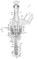
- FIG. 1 is a longitudinal sectional view of a fuel injection valve according to an embodiment of the present disclosure.
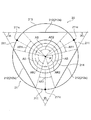
- FIG. 2 is an enlarged perspective view of a rear end portion of a valve body of the fuel injection valve shown in FIG. 1.
- FIG. 2 is an enlarged plan view of a rear end portion of a valve body of the fuel injection valve shown in FIG. 1.
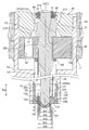
- FIG. 2 is an enlarged longitudinal sectional view of the vicinity of a rear end of a valve body of the fuel injection valve shown in FIG. 1.
- FIG. 2 is an enlarged longitudinal sectional view of the vicinity of a distal end portion of a valve body of the fuel injection valve shown in FIG. 1.
- FIG. 2 is a schematic view of a valve body and parts near the valve body of the fuel injection valve shown in FIG. 1.
- FIG. 1 is a longitudinal sectional view of the fuel injection valve 1 according to an embodiment of the present disclosure.
- 2 and 3 are an enlarged perspective view and an enlarged plan view of the rear end 21 of the valve element 20 of the fuel injection valve 1 shown in FIG.
- FIG. 4 is an enlarged longitudinal sectional view of the vicinity of the rear end 21 of the valve element 20 of the fuel injection valve 1 shown in FIG.
- FIG. 5 is an enlarged longitudinal sectional view of the vicinity of the distal end portion 23 of the valve element 20 of the fuel injection valve 1 shown in FIG.
- FIG. 6 is a schematic diagram of the valve body 20 and parts near the valve body 20 of the fuel injection valve 1 shown in FIG.
- the fuel injection valve 1 of the present embodiment has a cylindrical nozzle body 10 and an injection provided at a tip end in an axial direction Da (hereinafter, simply referred to as “axial direction Da”) along a central axis A of the nozzle body 10. It has a hole 11 and a valve body 20 that extends in the axial direction Da and has a tip 23 that opens and closes the injection hole 11.
- the fuel injection valve 1 has a movable core 30 that is engaged with the rear end 21 of the valve body 20 and moves in the axial direction Da together with the valve body 20, and a cylindrical core that sucks the movable core 30 by magnetic attraction.
- the fixed core 40 includes a coil 50 for generating a magnetic attractive force to the fixed core 40.
- the rear end portion 21 of the valve body 20 is an end portion (also referred to as a base end portion) of the valve body 20 opposite to the distal end portion 23 in the axial direction Da.
- the fuel injection valve 1 of the present embodiment has the following configuration as a first feature.
- the diameter of the valve element insertion hole 31 formed of a through hole formed in the center axis of the movable core 30 is ⁇ B
- the outer diameter of the intermediate portion 22 of the valve element 20 that slides with the valve element insertion hole (through hole) 31 is ⁇ C.
- the diameter of the slide between the spherical portion 230 on the distal end side (downstream side) of the valve body 20 and the distal end member 12 having the injection hole 11 is ⁇ D
- the spherical portion 230 on the distal end side (downstream side) of the valve body 20 is ⁇ D.
- Is the outermost diameter (spherical diameter) of ⁇ E and is the minimum diameter portion located at the rear end side (upstream side) of the spherical portion 230 at the front end side (downstream side) of the valve body 20 and at the intermediate portion 22 of the valve body 20.
- the outer diameter of the certain constricted portion 223 is ⁇ F
- the outer diameter satisfies ⁇ B> ⁇ C> ⁇ D> ⁇ E> ⁇ F
- the side wall of the movable core 30 does not contact the inner peripheral surface of the nozzle body 10. .
- the distal end portion 23 of the valve body 20 has a spherical portion 230 that slides on the inner peripheral surface of the distal end member 12 of the nozzle body 10, and between the distal end portion 23 and the rear end portion 21 of the valve body 20.
- the intermediate portion 22 is inserted into a valve element insertion hole 31 formed of a through hole formed in the movable core 30 and slides with the valve element insertion hole (through hole) 31.
- the diameter of the valve element insertion hole (through hole) 31 formed in the center axis of the movable core 30 is ⁇ B
- the valve element insertion hole (through hole) 31 The outer diameter of the insertion portion 222 in the intermediate portion 22 of the valve body 20 that slides with ⁇ C, the diameter of the inner peripheral surface of the distal end member 12 of the nozzle body 10 that slides with the spherical portion 230 of the valve body 20 is ⁇ D
- the outermost diameter (spherical diameter) of the spherical portion 230 of the valve body 20 is ⁇ E, and the neck at the intermediate portion 22 of the valve body 20 is When the outer diameter of the parts 223 and ⁇ F, ⁇ B> ⁇ C> ⁇ D> ⁇ E> met .phi.F, and the inner peripheral surface side and the nozzle body 10 of the movable core 30 and is composed of a shape relationship without contact.
- the fuel injector 1 of the present embodiment has the following configuration as a second feature.
- the valve body 20 is formed of one member from the rear end 21 to the front end 23. Further, the distal end portion 23 of the valve body 20 has a spherical portion 230, and the distal side sliding portion 231 of the spherical portion 230 that slides on the inner peripheral surface 121 of the distal end member 12 of the nozzle body 10, and the nozzle body 10 And the seat portion 232 of the spherical portion 230 that is grounded (seated) with the seat surface 124 of the distal end member 12 are formed of the same spherical surface.
- the fuel injection valve 1 of the present embodiment has the following configuration as a third feature.
- the nozzle body 10 has a concave tip member 12 in which the injection hole 11 is formed and which receives the tip portion 23 of the valve body 20.
- the valve element 20 is formed of one member from the rear end 21 to the front end 23, and has a rear end sliding portion 211 and a front end sliding portion 231 at the rear end 21 and the front end 23, respectively.
- the valve body 20 slides in the axial direction Da while the rear end side sliding portion 211 of the rear end portion 21 is in contact with the inner peripheral surface 41 of the fixed core 40 and slides in the axial direction Da.
- the fuel injection valve 1 mainly includes the nozzle body 10, the valve body 20, the movable core 30, the fixed core 40, and the coil 50.
- the fuel injection valve 1 includes, for example, a coil bobbin 51, a coil spring 61, an adjustment member 62, a small coil spring 63, a housing 70, a resin portion 80, and a filter 90.
- the nozzle body 10 has a tip member 12.
- the nozzle body 10 is provided, for example, in a substantially cylindrical shape extending in the axial direction Da, and has an injection hole 11 at the tip.
- a round rod-shaped or column-shaped valve element 20 extending in the axial direction Da is inserted into the nozzle body 10.
- the nozzle main body 10 has a small-diameter portion 13 on the front end side where the injection hole 11 is provided, and has a large-diameter portion 14 on the rear end opposite to the injection hole 11.
- the outer diameter of the large diameter portion 14 is larger than the outer diameter of the small diameter portion 13.
- the small-diameter portion 13 has a concave internal space 130 that opens to the distal end side inside the distal end portion, and the distal end member 12 is inserted or press-fitted into the concave internal space 130.
- the distal end member 12 has a concave shape, and is fixed to the small-diameter portion 13 by, for example, welding the entire outer periphery of the bottom surface, that is, the distal end surface to the inner peripheral edge of the opening at the distal end of the small-diameter portion 13. .
- the small-diameter portion 13 has a groove 131 (in the illustrated example, two upper and lower grooves 131) formed on the outer peripheral surface of the distal end portion, and a combustion gas seal member 15 such as a resin chip seal is fitted into the groove 131. ing.
- the large diameter portion 14 has a bottomed cylindrical internal space 140 having an opening at the end (that is, the rear end) on the fixed core 40 side, and an annular or cylindrical movable core is provided in the internal space 140. 30 are housed (with a gap). At the center of the bottom of the internal space 140 of the large-diameter portion 14, a cylindrical concave portion 141 is further provided, and a small portion for urging the movable core 30 away from the injection hole 11 in the concave portion 141, that is, in the valve opening direction. One end of the coil spring 63 is housed.
- the large-diameter portion 14 has a stepped cylindrical fixed core 40 with a distal end press-fitted inside the opening of the internal space 140, and the nozzle body 10 (the large-diameter portion 14) and the fixed core 40 are joined by welding. Have been. Thereby, the gap between the nozzle body 10 and the fixed core 40 is sealed, and the space inside the large diameter portion 14 is sealed.
- a cylindrical coil bobbin 51 and a coil 50 wound around the coil bobbin 51 are disposed on the outer periphery of the large diameter portion 14 of the nozzle body 10 and the distal end of the fixed core 40, and a resin portion 80 is provided on the outer periphery of the coil bobbin 51.
- a cylindrical housing 70 having a bottom is fixed.
- the valve body 20 includes, for example, a plurality of rear end sliding portions 211 and a plurality of rear end sliding portions 211 on a rear end 21 opposite to the front end 23 that opens and closes the injection hole 11. It has a flow path forming portion 212 and an annular or short columnar engaging portion 213.
- the valve body 20 has a rear end side sliding portion 211 and a front end side sliding portion 231 at the rear end portion 21 and the front end portion 23, respectively, as shown in FIGS. 1 to 5, for example.
- the valve body 20 has a gap G1 between the outer peripheral surface 221 of the intermediate portion 22 between the rear end portion 21 and the distal end portion 23 and the inner peripheral surface 16 of the nozzle body 10.
- the valve body 20 is made of, for example, a metal material such as SUS or the like, and is composed of one member from the rear end 21 to the front end 23. That is, the entirety of the valve body 20 including the rear end portion 21, the front end portion 23, and the intermediate portion 22 therebetween is made of, for example, one material, and mechanical parts such as welded joints and screws between the respective parts are provided. It does not have a good joint. More specifically, the valve body 20 is manufactured by, for example, cutting a single rod-shaped or columnar metal material using a lathe or a machining center, and grinding using a centerless grinder.
- a plurality of rear end side sliding portions 211 of the rear end portion 21 of the valve body 20 are arranged in the circumferential direction of the rear end portion 21 on the side opposite to the front end portion 23 on the injection hole 11 side in the axial direction Da of the valve body 20. They are provided at intervals.
- the valve body 20 is provided with, for example, three rear end side sliding portions 211 at intervals in the circumferential direction of the rear end portion 21. Note that the rear end portion 21 may have two rear end side sliding portions 211 in the circumferential direction, or may have four or more rear end side sliding portions 211 in the circumferential direction.
- the engaging portion 213 formed of the end of the rear end portion 21 adjacent to the movable core 30 in the axial direction Da, and the intermediate portion 22 between the rear end portion 21 and the front end portion 23 are connected to the central axis A of the nozzle body 10. And a cylindrical outer peripheral surface centered on the central axis A ′ of the valve body 20 which is substantially coaxial with the valve body 20. Further, in the valve body 20, the outer diameter of the engaging portion 213, which is the end portion of the rear end portion 21 adjacent to the movable core 30, is larger than the outer diameter of the intermediate portion 22, as shown in FIGS. Then, the intermediate portion 22 is inserted into the movable core 30 (with a gap) through the valve body insertion hole 31 formed with a through hole, so that the rear end portion 21 is engaged with the movable core 30.
- the plurality of rear end side sliding portions 211 of the rear end portion 21 are provided, for example, at equal intervals in the circumferential direction of the rear end portion 21. That is, as shown in FIG. 3, the angular interval AS of the center 211c of the rear end sliding portion 211 in the circumferential direction of the rear end 21 is equal.
- the angular interval AS between the center 211c of the side sliding portion 211 is 120 °.
- rear end side sliding portions 211 When four rear end side sliding portions 211 are provided at intervals in the circumferential direction of the rear end portion 21, the rear end portions adjacent to each other via the flow path forming portion 212 in the circumferential direction of the rear end portion 21.
- the angular interval AS between the centers 211c of the side sliding portions 211 is 90 °.
- the rear end side sliding portion 211 of the rear end portion 21 is, for example, a portion that is left without being cut off of the cylindrical rear end portion 21 of the valve body 20 and has a partially cylindrical outer peripheral surface. . That is, the rear end side sliding portion 211 is configured by a part of the outer peripheral surface of the cylindrical rear end portion 21 having a plurality of notches. Note that a plurality of flow path forming portions 212 are provided by cutting out a part of the outer peripheral surface of the cylindrical rear end portion 21.
- the plurality of flow path forming portions 212 are provided between the adjacent rear end sliding portions 211 and between the rear end sliding portions 211 and radially inside the rear end portion 21 with respect to the rear end sliding portions 211. Have been. As shown in FIGS. 1 and 4, the flow path forming portion 212 includes a rear end portion 21 of the valve body 20 and an inner peripheral surface 41 of the cylindrical fixed core 40 into which the rear end portion 21 of the valve body 20 is inserted. To form a fuel flow channel FC. When the rear end portion 21 has three rear end side sliding portions 211 in the circumferential direction, three flow path forming portions 212 are formed on the rear end portion 21.
- the rear end portion 21 has four rear end side sliding portions 211 in the circumferential direction, four flow path forming portions 212 are formed on the rear end portion 21. That is, the number of the rear end side sliding portions 211 provided on the rear end portion 21 is equal to the number of the flow path forming portions 212.
- a plurality of rear end side sliding portions 211 are provided at equal intervals in the circumferential direction of the rear end portion 21, a plurality of flow path forming portions 212 are formed at equal intervals in the circumferential direction of the rear end portion 21.
- the flow path forming portion 212 has a flat surface 212a provided between the adjacent rear end sliding portions 211. As shown in FIG. 3, for example, when the rear end portion 21 has three rear end side sliding portions 211 at equal intervals in the circumferential direction, the flow path forming portion 212 adjacent via the rear end side sliding portion 211 is provided. The included angle IA between the flat surfaces 212a is 60 °. Further, for example, when the rear end portion 21 has four rear end sliding portions 211 at equal intervals in the circumferential direction, the flat surface 212 a of the flow path forming portion 212 adjacent via the rear end sliding portion 211 is formed. The included angle IA between them is 90 °.
- the angle of the included angle IA is equal to the inner angle of a regular polygon having the same number of vertices as the number of the rear end sliding portions 211.
- the angle range AR2 of the portion where the flow path forming portion 212 is formed is the same as the angle range AR2 of the portion where the rear end side sliding portion 211 is formed. It is larger than the angle range AR1. That is, of the cylindrical outer peripheral surface on the coil spring 61 side with respect to the engaging portion 213 of the rear end portion 21, less than half a circumference is left as a partial cylindrical surface constituting the rear end sliding portion 211. is there. In other words, at least a half of the cylindrical outer peripheral surface of the rear end portion 21 closer to the coil spring 61 than the engaging portion 213 is cut out to form the flow path forming portion 212.
- the engagement portion 213 is provided on the distal end side of the valve body 20 with respect to the flow path forming section 212 and is provided so as to project radially outward from the flow path forming section 212.
- the engagement portion 213 is a cylinder which is continuous with the outer peripheral surface of the rear end side sliding portion 211 without any level difference over the entire circumferential direction of the rear end portion 21. It has an outer peripheral surface of a shape. That is, the end face of the engaging portion 213 facing the movable core 30 is defined by the outer peripheral surface of the engaging portion 213 which is the end of the rear end portion 21 of the valve body 20 on the movable core 30 side as the outer peripheral edge. This is an annular end surface having the outer peripheral surface 221 of the intermediate portion 22 as the inner peripheral edge.
- the outer diameter of the engaging portion 213 is smaller than the inner diameter (hole diameter) of the through hole 42 provided at the center of the fixed core 40 in the example shown in FIGS. It is provided movably in the direction Da.
- the clearance between the outer peripheral surface of the rear end portion 21 of the valve element 20, that is, the outer peripheral surface of the engaging portion 213 and the rear end sliding portion 211, and the inner peripheral surface 41 of the fixed core 40 is, for example, It is about 10 ⁇ m to 30 ⁇ m, more preferably about 20 ⁇ m to 30 ⁇ m.
- the intermediate portion 22 of the valve body 20 has a stepped shaft shape, and a relatively large-diameter insertion portion 222 slidably inserted into the movable core 30 (the valve body insertion hole 31 formed of a through hole); A relatively small diameter (constant outer diameter) constricted portion 223 extending in the axial direction Da from the insertion portion 221 to the distal end portion 23.
- the constricted portion 223 is located on the distal end side (downstream side) of the insertion portion 22 and on the rear end side (upstream side) of (the spherical portion 230 of) the distal end portion 23.
- the constricted portion 223 is inserted (disposed inside) in the nozzle main body 10 with a gap G1 between itself and the inner peripheral surface 16 of the nozzle main body 10.
- the distal end side of the distal end portion 23 of the valve body 20 is a spherical portion 230, and the outermost diameter (spherical diameter) of the spherical portion 230 is outside the insertion portion 222 of the intermediate portion 22. It is smaller than the diameter and larger than the outer diameter of the constricted part 223 of the intermediate part 22.
- the distal end portion 23 of the valve body 20 is received by the concave distal end member 12 provided at the distal end of the cylindrical nozzle body 10, and the distal side sliding portion 231 is formed on the outer peripheral surface (spherical surface) of the spherical portion 230 of the valve body 20.
- a plurality of notches 123 for forming a fuel flow channel FC are provided at equal intervals in the circumferential direction of the concave portion 122. I have.
- the valve body 20 is configured such that the seat portion 232 provided on the distal end side (in other words, on the downstream side) of the distal end side sliding portion 231 of the spherical portion 230 on the distal end side of the distal end portion 23 is attached to the distal end member 12 of the nozzle body 10.
- the fuel flow channel FC between the valve body 20 and the seat surface 124 is closed, and the injection hole 11 provided on the tip end side of the seat surface 124 is closed.
- a fuel flow channel FC is formed between the valve body 20 and the seating surface 124.
- the injection hole 11 provided on the tip side is opened.
- the valve body 20 is provided with, for example, a conical convex portion 233 having a rounded tip (in the illustrated example, a cone having a vertex angle of about 90 °) on the tip end side of the tip portion 23 in the axial direction Da with respect to the seat portion 232. Have been.
- the tip member 12 of the nozzle body 10 has, for example, a concave seating surface 124 that receives the (spherical portion) 230 of the distal portion 23 of the valve body 20 at the center of the concave portion 122 at the bottom.
- the seat surface 124 is provided in a truncated cone shape (in the illustrated example, a truncated cone shape having a vertex angle of about 90 °) whose diameter gradually decreases toward the tip of the nozzle body 10 in the axial direction Da, and the injection hole 11 is opened. ing.
- the seat surface 124 and the spherical portion 230 of the valve body 20 are substantially in line contact over the entire circumference of the seat surface 124, so that the fuel between the seat surface 124 and the valve body 20 is The channel FC is closed. Further, when the spherical portion 230 (the seat portion 232 of) the valve body 20 is separated from the seat surface 124, a fuel flow channel FC between the seat surface 124 and the valve body 20 is formed, and the fuel channel FC is opened to the seat surface 124. Fuel is injected through the injection holes 11.
- the distal end member 12 is formed with a receiving concave portion 125 having a concave curved bottom portion on the distal end side in the axial direction Da with respect to the seat surface 124, for example, at the center of the concave portion 122 on the bottom portion.
- the receiving concave portion 125 is provided so as to receive at least a part (specifically, a distal end portion) of the convex portion 233 at the distal end of the valve body 20 in a state where the injection hole 11 is closed.
- the fixed core 40 is a cylindrical member that sucks the movable core 30 by magnetic attraction. More specifically, the fixed core 40 has a substantially cylindrical shape having irregularities on the outer peripheral surface.
- a generally cylindrical coil bobbin 51 is arranged on the outer periphery of the distal end of the fixed core 40.
- a coil 50 wound in a cylindrical shape is disposed on the outer periphery of the coil bobbin 51. The ends of the winding start and end of the coil 50 are connected to a power supply terminal 811 of a connector 81 of the resin portion 80 via wiring not shown.
- the fixed core 40 is provided with a through hole 42 along the central axis A (in other words, substantially coaxial with the central axis A).
- the through hole 42 of the fixed core 40 forms a flow channel FC for introducing fuel.
- the distal end surface of the fixed core 40 facing the movable core 30 may be covered by plating such as hard chrome plating or electroless nickel plating. Good.
- An opening 43 for introducing fuel is provided on the rear end surface of the fixed core 40 opposite to the front end surface. The filter 90 is inserted and fixed from the opening 43 to the through hole 42 of the fixed core 40.
- the fixed core 40 has an enlarged diameter portion 44 whose diameter increases as the vicinity of the distal end surface of the through hole 42 approaches the distal end surface.
- the fixed core 40 has, on the cylindrical inner peripheral surface 41, a truncated cone-shaped enlarged portion 44 whose inner diameter increases as approaching the movable core 30.
- the enlarged diameter portion 44 is, for example, a cylinder-shaped rear end portion 21 of the valve body 20 in a valve-closed state in which the valve body 20 (the seat portion 232 of the distal end portion 23) is in contact with the seat surface 124 and the injection hole 11 is closed. Is configured to be accommodated. That is, when the valve body 20 is at the valve closing position, the enlarged diameter portion 44 of the fixed core 40 is provided so as to overlap the position of the engaging portion 213 of the rear end 21 of the valve body 20 in the axial direction Da. ing.
- the enlarged diameter portion 44 of the fixed core 40 is, for example, at least a part of the flow path forming portion 212 of the rear end portion 21 of the valve body 20 (specifically, the tip end) when the injection hole 11 is closed. ) Is disposed inside the enlarged diameter portion 44, and a fuel flow channel FC is formed between the flow channel forming portion 212 and the inner peripheral surface 41 of the fixed core 40. That is, when the valve body 20 is at the valve closing position, the enlarged diameter portion 44 of the fixed core 40 overlaps at least a part of the flow path forming portion 212 of the rear end 21 of the valve body 20 in the axial direction Da. It is provided in.
- the adjusting member 62 is, for example, pressed into the through hole 42 of the fixed core 40 and fixed inside the fixed core 40.
- the coil spring 61 is disposed in the through hole 42 inside the fixed core 40 and is provided so as to urge the valve body 20 toward the injection hole 11 in the axial direction Da. More specifically, the coil spring 61 is compressed between the adjusting member 62 fixed to the fixed core 40 and the rear end 21 of the valve element 20 inserted into (the through hole 42 of) the fixed core 40. The valve body 20 is urged in the axial direction Da toward the injection hole 11.
- the initial load that the coil spring 61 presses the distal end portion 23 of the valve body 20 against the seat surface 124 provided on the distal end member 12 of the nozzle body 10 is adjusted.
- the adjustment member 62 supports the coil spring 61 by the end on the coil spring 61 side, thereby preventing the coil spring 61 from being displaced in a direction intersecting the axial direction Da.
- the valve body 20 has a convex portion 214 that protrudes in the axial direction Da from an end surface of the rear end portion 21 opposite to the movable core 30 (that is, the rear end surface) and engages with the inside of the coil spring 61.
- the protruding portion 214 is a substantially columnar protrusion having a chamfered corner at the distal end, and is provided so as to fit exactly inside the end of the coil spring 61 on the valve body 20 side. The displacement in the direction intersecting with the direction Da is prevented.
- the coil spring 61 is held inside the fixed core 40 with a gap G2 between the coil spring 61 and the inner peripheral surface 41 of the fixed core 40.
- the movable core 30 is a thick cylindrical member that is engaged with the rear end portion 21 of the valve body 20 and moves in the axial direction Da together with the valve body 20.
- the movable core 30 is separate from the valve body 20, and has a valve body insertion hole 31 formed at the center thereof and formed with a through hole for inserting the valve body 20 in the axial direction Da.
- the inner diameter of the valve element insertion hole 31 (that is, the hole diameter of the through hole) is smaller than the outer diameter of the rear end part 21 of the valve element 20 including the outer diameter of the engagement part 213, and
- the valve body insertion hole 31 is formed so as to be slightly larger than the outer diameter of the portion on the distal end side (the intermediate portion 22 and the distal end portion 23).
- the movable core 30 penetrates the movable core 30 in the axial direction Da at a position eccentric from the central valve body insertion hole 31 to form a fuel flow channel FC, and has a slightly smaller diameter than the valve body insertion hole 31. Eccentric through-hole 32.
- the side surface (outer peripheral surface) of the movable core 30 and the inner peripheral surface of (the internal space 140 of the large-diameter portion 14 of) the nozzle body 10 are configured so as not to be in contact with each other. That is, the movable core 30 is movably inserted into the nozzle main body 10 with a gap G3 between the movable core 30 and the inner peripheral surface of the nozzle main body 10.
- the upper end surface or the collision surface of the fixed core 40 facing the movable core 30 is covered with plating such as hard chrome plating or electroless nickel plating. May be. Thereby, even when relatively soft soft magnetic stainless steel is used as the material of the movable core 30, the durability and reliability of the movable core 30 can be secured.
- the small coil spring 63 is housed in the internal space 140 of the large diameter portion 14 of the nozzle body 10.
- the small coil spring 63 has a distal end supported by the bottom of a concave portion 141 provided at the center of the bottom of the internal space 140 of the large-diameter portion 14, and a rear end located below the movable core 30 on the side opposite to the fixed core 40. It is in contact with the end face, and is held in a compressed state between the movable core 30 and the nozzle body 10. Thus, the small coil spring 63 biases the movable core 30 toward the fixed core 40.
- the housing 70 has a bottomed cylindrical shape, and the large-diameter portion 14 of the nozzle body 10 is inserted into a bottom through hole 71 provided at the center of the bottom.
- the housing 70 is welded, for example, over the entire circumference between the opening edge of the bottom through hole 71 provided on the bottom and the outer peripheral surface of the large diameter portion 14 of the nozzle body 10, so that the large diameter portion of the nozzle body 10 is welded. 14.
- the housing 70 is disposed so as to surround the distal end portion of the fixed core 40, the coil bobbin 51, and the outer periphery of the coil 50.
- the inner peripheral surface of the housing 70 faces the large diameter portion 14 of the nozzle body 10 and the coil 50 to form an outer peripheral yoke portion.
- the resin portion 80 is filled between the fixed core 40, the coil bobbin 51 and the coil 50, and the housing 70, and covers an outer peripheral surface of the fixed core 40 excluding a rear end portion, and has a power supply terminal 811. 81 are molded. As described above, the toroidal magnetic path including the fixed core 40, the movable core 30, the large diameter portion 14 of the nozzle body 10, and the housing 70 is formed around the coil 50.
- a terminal 811 of the connector 81 is connected to a connection terminal of a plug (not shown) and connected to a high-voltage power supply or a battery power supply, and energization of the coil 50 is controlled by an engine control unit (ECU).
- ECU engine control unit
- the elastic force of the coil spring 61 for urging the valve body 20 toward the seat surface 124 at the tip of the nozzle body 10 is smaller than the elastic force of the small coil spring 63 for urging the movable core 30 toward the fixed core 40. large.
- the spherical portion 230 (the seat portion 232) of the distal end portion 23 of the valve body 20 is pressed against the seating surface 124 of the distal end member 12 of the nozzle body 10, and is provided on the seating surface 124.
- the flow path FC to the selected injection hole 11 is in a closed state (see FIGS. 1 and 5).
- the valve body 20 moves in the axial direction Da toward the fixed core 40, the (the seat portion 232) of the spherical portion 230 of the distal end portion 23 of the valve body 20 separates from the seating surface 124 of the distal end member 12 of the nozzle body 10. Then, the flow path FC between the valve body 20 and the seat surface 124 to the injection hole 11 is opened, and the injection hole 11 is opened.
- the valve element 20 is in such an open position, the fuel supplied from the opening 43 at the rear end of the fixed core 40 via the filter 90 is supplied to the fuel injection valve 1 through the through hole of the fixed core 40. It flows along the axial direction Da toward the front end side of the nozzle body 10 through 42.
- the fuel further passes through the adjusting member 62 and the coil spring 61 arranged in the through hole 42 of the fixed core 40, and flows through the flow path forming portion 212 of the rear end 21 of the valve element 20 and the through hole 42 of the fixed core 40. It flows through the flow path FC formed between the outer peripheral surface 41 and the inner surface 140 of the large diameter portion 14 of the nozzle body 10 through the eccentric through hole 32 of the movable core 30.
- the fuel that has flowed into the internal space 140 of the large-diameter portion 14 of the nozzle body 10 flows between the intermediate portion 22 of the valve body 20 and the inner peripheral surface 16 of the small-diameter portion 13 of the nozzle body 10 (gap G1).
- the gas flows through a flow channel FC formed between the spherical portion 230 (the seat portion 232 of) the distal end portion 23 of the body 20 and the seating surface 124 of the distal end member 12, and flows through the injection hole 11 opened in the seating surface 124. It is injected into the combustion chamber of the engine.
- the rear end 21 of the valve body 20 is urged by the coil spring 61, and the movable core 30 and the valve body 20 engaged with the rear end 21 of the valve body 20 are both moved in the axial direction Da of the nozzle body 10.
- the nozzle body moves toward the distal end, and the spherical portion 232 of the distal end portion 23 of the valve body 20 contacts the seating surface 124 of the distal end member 12 of the nozzle body 10.
- the flow path FC between (the seat portion 232 of) the spherical portion 230 of the distal end portion 23 of the valve body 20 and the seating surface 124 of the nozzle body 10 is closed, and the injection hole 11 is closed by the valve body 20.
- the valve is closed, and fuel injection through the injection hole 11 is stopped.
- the valve element 20 has the plurality of rear end side sliding portions 211, the plurality of flow path forming portions 212, and the engaging portions 213.
- the plurality of rear end side sliding portions 211 are provided at intervals in the circumferential direction of the rear end portion 21.
- the plurality of flow path forming portions 212 are provided between the adjacent rear end sliding portions 211 and are located radially inward of the rear end portion 21 from the rear end sliding portions 211. It is provided in.
- the engaging portion 213 is provided on the distal end side of the valve body 20 with respect to the flow path forming section 212, and projects radially outward from the flow path forming section 212.
- At least one of the plurality of rear end sliding portions 211 contacts the inner peripheral surface 41 of the fixed core 40 and slides in the axial direction Da. 213 is configured such that the end face of the movable core 30 facing the movable core 30 is in contact with the movable core 30.
- valve body 20 can be supported and guided by the inner peripheral surface 41 of the fixed core 40 at the rear end 21 of the valve body 20 on which a radial force acts from the coil spring 61. Therefore, the distance in the axial direction Da between the position where the radial force acts on the valve element 20 and the rear end sliding section 211 can be reduced, and the diameter of the valve element 20 acting on the rear end sliding section 211 can be reduced.
- the load in the direction can be reduced dynamically.
- the rear of the valve body 20 is compared with a case where the engaging portion 213 is not provided.
- the area of the surface of the end 21 facing the movable core 30 can be increased. Thereby, the force per unit area acting between the rear end portion 21 of the valve element 20 and the movable core 30 can be reduced, and the durability can be improved as compared with the related art.
- the fuel injection valve 1 of the present embodiment has the following configuration as a first feature.
- the diameter of the valve element insertion hole 31 formed of a through hole formed in the center axis of the movable core 30 is ⁇ B
- the outer diameter of the intermediate portion 22 of the valve element 20 that slides with the valve element insertion hole (through hole) 31 is ⁇ C.
- the diameter of sliding between the distal end member 12 having the injection hole 11 that slides on the distal side sliding portion 231 of the spherical portion 230 on the distal side (downstream side) of the valve body 20 is ⁇ D, and the distal side of the valve body 20 (
- the outermost diameter (spherical diameter) of the distal side sliding portion 231 of the spherical portion 320 on the downstream side is ⁇ E, and the outermost diameter (spherical diameter) is located on the rear end side (upstream side) of the spherical portion 230 on the distal side (downstream side) of the valve element 20.
- the distal end portion 23 of the valve body 20 has a spherical portion 230 having a distal side sliding portion 231 that slides on the inner peripheral surface of the distal end member 12 of the nozzle body 10.
- An intermediate portion 22 between the rear end portion 21 and the rear end portion 21 is inserted into a valve body insertion hole 31 formed of a through hole formed in the movable core 30 and slides with the valve body insertion hole (through hole) 31. And a constricted portion 223 located downstream of the insertion portion 222 and upstream of the spherical portion 230.
- the diameter of the valve element insertion hole (through hole) 31 formed in the center axis of the movable core 30 is ⁇ B
- the outer diameter of the insertion portion 222 in the intermediate portion 22 of the valve body 20 that slides with the body insertion hole (through hole) 31 is ⁇ C
- the diameter of the inner peripheral surface of the distal end member 12 is ⁇ D, and the distal side of the spherical portion 230 of the valve body 20 slides.
- the valve element 20 can be inserted from the upstream side of the filter 90 after the fuel flow path FC of the fuel injection valve 1 is manufactured.
- the fuel injection valve 1 without the valve body 20 can be cleaned in a state where the fuel passage FC is largely secured, it is excellent in contaminant discharge properties, and can cause serious accidents such as unburned fuel. Can be avoided. Therefore, the reliability of the fuel injection valve 1 is improved. Further, in order to cope with the increasingly strict exhaust gas regulations year by year, it is necessary to operate even at a high fuel pressure, and for that purpose, the outer diameter of the nozzle body 10 needs to be reduced.
- the outer diameter of the nozzle body 10 can be reduced. Furthermore, since the side surface of the movable core 30 and the inner peripheral surface of the nozzle main body 10 are configured so as not to be in contact with each other, there is no resistance generated when the movable core 30 comes into contact with the nozzle main body 10, so that the fuel injection amount can be reduced. Variations are small and there is no wear, so durability is also improved.
- the fuel injection valve 1 of the present embodiment has the following configuration as a second feature.
- the valve body 20 is formed of one member from the rear end 21 to the front end 23. Further, the distal end portion 23 of the valve body 20 has a spherical portion 230, and the distal side sliding portion 231 of the spherical portion 230 that slides on the inner peripheral surface 121 of the distal end member 12 of the nozzle body 10, and the nozzle body 10 And the seat portion 232 of the spherical portion 230 that is grounded (seated) with the seat surface 124 of the distal end member 12 are formed of the same spherical surface.
- a plurality of functions of FC formation can be integrated into one component. Therefore, the number of parts can be reduced, productivity can be improved, and manufacturing costs can be reduced. Further, since the distal end side sliding portion 231 of the valve body 20 is a spherical body, the area of the valve body 20 in contact with the inner peripheral surface 121 of the concave portion 122 of the distal end member 12 becomes invariant regardless of the degree of inclination, so that the fuel Can be made uniform. In addition, since the sliding clearance is constant, the coaxial tolerance of the inner peripheral surface 121 of the concave portion 122 of the distal end member 12 can be relaxed, so that productivity can be improved and manufacturing cost can be reduced.
- the fuel injection valve 1 of the present embodiment has the following configuration as a third feature.
- the nozzle body 10 has a concave tip member 12 in which the injection hole 11 is formed and which receives the tip portion 23 of the valve body 20.
- the valve element 20 is formed of one member from the rear end 21 to the front end 23, and has a rear end sliding portion 211 and a front end sliding portion 231 at the rear end 21 and the front end 23, respectively.
- the valve body 20 slides in the axial direction Da while the rear end side sliding portion 211 of the rear end portion 21 is in contact with the inner peripheral surface 41 of the fixed core 40 and slides in the axial direction Da. Is configured to slide in the axial direction Da by contacting the inner peripheral surface 121 of the concave portion 122 of the distal end member 12.
- valve body 20 is in the valve closing position in contact with the seating surface 124 of the distal end member 12 of the nozzle body 10.
- valve body 20 is in the rear end side sliding portion of the rear end portion 21. Only 211 is supported by the inner peripheral surface 41 of the fixed core 40, and the distal sliding portion 231 of the distal end portion 23 does not have to contact the inner peripheral surface 121 of the recess 122 of the distal end member 12.
- valve body 20 includes the rear end side sliding portion 211 and the front side sliding portion 231 at the front end portion 23 and the rear end portion 21 in the axial direction Da, respectively, between the individual fuel injection valves 1,
- the contact area with the contact can be made more uniform. Thereby, the fuel injection amount between the individual fuel injection valves 1 can be made more uniform.
- distal-side sliding portion 231 not only at the rear end portion 21 of the valve body 20 but also at a position near the seating surface 124 of the distal end member 12 with which the spherical portion 230 of the distal end portion 23 of the valve body 20 contacts,
- the amount of inclination of the valve body 20 with respect to the center axis A of the nozzle body 10, that is, the inclination angle, can be reduced.
- the valve element 20 is formed of a single member from the rear end 21 to the distal end 23, the valve element 20 is guided by the rear end sliding portion 211 and the distal end sliding portion 231 and the flow path is formed.
- the plurality of functions of forming the fuel flow channel FC by the portion 212 can be integrated into one component. Therefore, the number of parts can be reduced, productivity can be improved, and manufacturing costs can be reduced.
- the valve body 20 is provided with three rear end side sliding portions 211 at intervals in the circumferential direction of the rear end portion 21 as described above.
- the wear resistance of the rear end side sliding portion 211 of the rear end portion 21 that satisfies the number of operations required for the valve body 20. Therefore, it is possible to provide the fuel injection valve 1 capable of improving the durability as compared with the related art.
- the range of the flow path forming portion 212 between the adjacent rear end sliding portions 211 can be increased, and the flow path formation It is possible to increase the cross-sectional area of the fuel flow channel FC between the portion 212 and the fixed core 40. Accordingly, it is possible to provide the fuel injection valve 1 which can reduce the pressure loss of the fuel in the flow path FC formed by the flow path forming section 212 and make the fuel injection amount more uniform than before.
- the rear end side sliding portions 211 of the rear end portion 21 of the valve element 20 are provided at equal intervals in the circumferential direction of the rear end portion 21.
- the cross-sectional area of the fuel flow channel FC formed by the flow channel forming portion 212 between the adjacent rear end sliding portion 211 and the rear end sliding portion 211 can be made uniform,
- the pressure acting on the flow path forming portion 212 can be made uniform by the fuel as a fluid.
- a radial force of the valve body 20 acts on the valve body 20 from the coil spring 61, only one of the rear end side sliding portions 211 contacts the fixed core 40.
- the other two rear end side sliding portions 211 of the rear end portion 21 of the valve body 20 do not contact the fixed core 40, and a sliding area between the rear end portion 21 of the valve body 20 and the fixed core 40.
- the sliding resistance By making the sliding resistance constant, the fuel injection amount of each fuel injection by the fuel injection valve 1 can be made uniform.
- the fuel injection valve 1 of the present embodiment includes a coil spring 61 that urges the valve body 20 toward the injection hole 11 in the axial direction Da.
- the valve body 20 has a convex portion 214 that protrudes in the axial direction Da from an end surface of the rear end portion 21 opposite to the movable core 30 (that is, the rear end surface) and engages with the inside of the coil spring 61.
- the radial movement of the coil spring 61 can be suppressed by the projection 214 of the rear end portion 21 of the valve body 20, and contact between the coil spring 61 and the inner peripheral surface 41 of the fixed core 40 can be suppressed. .
- the coil spring 61 has a gap G2 between the coil spring 61 and the inner peripheral surface 41 of the fixed core 40.
- the rear end side sliding portion 211 of the rear end portion 21 of the valve element 20 has a partially cylindrical outer peripheral surface, and the flow path forming portion 212 has a rear end portion.
- 21 has a flat surface 212a provided between the rear end side sliding portions 211.
- a flow path whose cross-sectional shape (cross-sectional shape perpendicular to the axial direction Da) is defined by an arc and a chord between the flat surface 212a of the flow path forming portion 212 and the inner peripheral surface 41 of the cylindrical fixed core 40.
- FC can be formed, the cross-sectional area of the flow channel FC can be increased, the flow channel resistance can be reduced, and the fuel injection amount of the fuel injection valve 1 can be made uniform.
- the angle of the included angle IA between the flat surfaces 212a of the adjacent flow path forming portions 212 via the rear end sliding portion 211 of the rear end portion 21 of the valve body 20 is: , 60 °.
- the cross-sectional shape of the portion of the rear end portion 21 of the valve element 20 where the flow path forming portion 212 is formed can be a substantially equilateral triangular shape having an arc-shaped apex portion.
- the angle range AR2 of the portion where the flow path forming portion 212 is formed is formed by the rear end side sliding portion 211. It is larger than the angle range AR1 of the portion that has been set.
- the fuel injection valve 1 which can reduce the pressure loss of the fuel in the flow path FC formed by the flow path forming section 212 and make the fuel injection amount more uniform than before.
- the cross-sectional shape of the portion of the rear end portion 21 of the valve element 20 where the flow path forming portion 212 is formed can be a substantially equilateral triangular shape having an arc-shaped apex portion. Thereby, the strength of the rear end portion 21 of the valve element 20 can be secured, and the durability of the fuel injection valve 1 can be improved.
- the rear end side sliding portion 211 of the rear end portion 21 of the valve element 20 has a partially cylindrical outer peripheral surface as described above, and has a flow path forming portion 212.
- the engaging portion 213 of the rear end portion 21 of the valve element 20 is provided on the distal end side of the valve element 20 with respect to the flow path forming section 212 and projects radially outward from the flow path forming section 212. It has a cylindrical outer peripheral surface that is continuous over the entire circumference of the rear end portion 21 in the circumferential direction and that is flush with the outer peripheral surface of the rear end side sliding portion 211.
- the valve body 20 can be compared with a case without the engaging portion 213.
- the area of the surface of the rear end 21 that contacts the movable core 30 can be increased.
- the engaging portion 213, which is the end of the rear end 21 on the movable core 30 side is continuous over the entire circumference of the rear end 21 in the circumferential direction, and is flush with the outer peripheral surface of the rear end sliding portion 211.
- the area of the surface in contact with the movable core 30 can be maximized. Thereby, the force per unit area acting between the rear end portion 21 of the valve element 20 and the movable core 30 can be reduced, and the durability can be improved as compared with the related art.
- burrs may be generated at a corner between the outer peripheral surface of the engaging portion 213 of the valve body 20 manufactured by rotary cutting and the surface facing the movable core 30.
- the engagement portion 213 has a cylindrical outer peripheral surface that is continuous over the entire circumference of the rear end portion 21 in the circumferential direction, the rear end portion 21 of the valve body 20 is rotated to remove corner burr in one step. Can be removed.
- the fixed core 40 has an enlarged diameter portion 44 on the inner peripheral surface 41 whose inner diameter increases as approaching the movable core 30, and expands when the injection hole 11 is closed.
- the engagement portion 213 of the rear end portion 21 of the valve body 20 is configured to be accommodated (with a gap) in the diameter portion 44. Thereby, a gap is formed between the engaging portion 213 of the rear end portion 21 of the valve element 20 and the enlarged diameter portion 44 of the inner peripheral surface 41 of the fixed core 40, and the fuel flow channel FC is formed. it can.
- the pressure loss of the fuel flowing between the engaging portion 213 of the rear end portion 21 of the valve element 20 and the enlarged diameter portion 44 of the inner peripheral surface 41 of the fixed core 40 is reduced, and the fuel of the fuel injection valve 1 is reduced.
- the injection amount can be made uniform.
- the fuel injection valve 1 of the present embodiment at least a part of the flow path forming portion 212 is arranged inside the enlarged diameter portion 44 with the injection hole 11 closed. More specifically, the fuel injection valve 1 of the present embodiment is configured such that the flow path FC between the distal end portion 23 of the valve body 20 reaching the injection hole 11 and the seating surface 124 is closed, The end (tip) on the movable core 30 side is accommodated in the enlarged diameter portion 44.
- the cross-sectional area of the fuel flow channel FC between the flow channel forming portion 212 of the rear end portion 21 of the valve element 20 and the enlarged diameter portion 44 of the inner peripheral surface 41 of the fixed core 40 can be increased. . Therefore, the pressure loss of the fuel flowing between the rear end portion 21 of the valve element 20 and the inner peripheral surface 41 of the fixed core 40 can be reduced, and the fuel injection amount of the fuel injection valve 1 can be made uniform.
- the fuel injection valve 1 of the present embodiment includes a portion of the rear end portion 21 adjacent to the movable core 30 in the axial direction Da (that is, the engaging portion 213) and an intermediate portion between the rear end portion 21 and the front end portion 23.
- the part 22 has a cylindrical outer peripheral surface centered on the central axis A ′ of the valve body 20.
- valve element 20 by forming the entire valve element 20 as one part cut out of one material, the dimensional accuracy of the valve element 20 can be improved, and the productivity can be improved, and the manufacturing cost of the valve element 20 can be improved. Can be reduced. Furthermore, compared to a case where each part of the valve body 20 is manufactured as a separate part and integrated by press-fitting or welding, it is possible to suppress the generation of foreign matters such as metal pieces generated at the time of press-fitting and spatters generated at the time of welding. . Accordingly, it is possible to suppress the occurrence of troubles of the valve body 20 such as fuel leakage due to foreign matter, and to make the fuel injection amount of the fuel injection valve 1 uniform.
- the outer diameter of the portion of the valve body 20 adjacent to the movable core 30 at the rear end portion 21 is the rear end portion 21 and the front end portion 23.
- the diameter of the intermediate portion 22 is larger than the outer diameter of the intermediate portion 22, and the intermediate portion 22 is inserted into (the valve body insertion hole 31 of) the movable core 30. That is, the inner diameter of the valve element insertion hole 31 of the movable core 30 is larger than the outer diameter of the intermediate portion 22 of the valve element 20 and smaller than the outer diameter of the engagement portion 213 of the rear end 21 of the valve element 20.
- the urging force of the coil spring 61 acting on the rear end portion 21 of the valve element 20 toward the tip of the nozzle body 10 applies the small coil spring 63 that urges the movable core 30 toward the fixed core 40.
- the end of the rear end 21 of the valve element 20 on the movable core 30 side is in contact with and engaged with the movable core 30.
- the valve body 20 moves together with the movable core 30 and the distal end member of the nozzle body 10. 12 is moved in the axial direction Da so as to be separated from the seating surface 124.
- the movable core 30 collides with the distal end surface of the fixed core 40, the movable core 30 rebounds toward the distal end of the nozzle body 10 opposite to the fixed core 40, that is, on the downstream side of the fuel.
- the valve body 20 inserted into the valve body insertion hole 31 of the movable core 30 continues to move the fuel leaving the injection hole 11 to the upstream side.
- valve element 20 overshoots from the position of the rear end face of the movable core 30 toward the rear end of the fixed core 40 that is on the upstream side of the fuel, and is thereafter urged by the coil spring 61, It again moves to the tip side of the nozzle body 10, which is the downstream side of the fuel. Therefore, when the coil 50 is energized, the valve body 20 engages with the movable core 30 having the rear end 21 adsorbed to the fixed core 40, and the (spherical portion 230 of the spherical portion 230 of the distal end portion 23). The flow path FC between the valve and the seat surface 124 is stopped at the open position where the valve is opened.
- the urging force of the coil spring 61 acting on the rear end 21 of the valve body 20 causes the rear end 21 of the valve body 20 to engage.
- the combined movable core 30 moves together with the valve body 20 in the axial direction Da toward the tip of the nozzle body 10.
- the spherical portion 230 (the seat portion 232) of the distal end portion 23 of the valve body 20 collides with the seating surface 124 of the distal end member 12 of the nozzle body 10
- the movable core 30 is separate from the valve body 20. Then, the movement of the nozzle body 10 toward the distal end side is continued by the inertial force. Further, the valve body 20 rebounds in the valve opening direction after the spherical portion 230 (the seat portion 232) of the distal end portion 23 collides with the seating surface 124 of the distal end member 12 of the nozzle body 10.
- the inertial force acting on the movable core 30 is smaller than when the movable core 30 and the valve body 20 are integrated. Therefore, the repulsive force received after compressing the small coil spring 63 decreases. Therefore, the rebound of the movable core 30 in the valve opening direction, that is, toward the fixed core 40, is suppressed, and the phenomenon that the valve body 20 is moved again in the valve opening direction after colliding with the seat surface 124 is less likely to occur. As a result, the rebound of the valve body 20 is minimized, and after the energization of the coil 50 is interrupted, the flow path FC between the valve body 20 and the seat surface 124 is opened, and fuel is injected at random. That is, the so-called secondary injection phenomenon is suppressed, and the emission can be reduced.
- the outer diameter of the engagement portion 213 of the rear end portion 21 of the valve body 20 is smaller than the inner diameter of the fixed core 40, and the inside of the fixed core 40 extends in the axial direction Da. It is provided movably.
- the valve body 20 is located between the outer peripheral surface 221 of the intermediate portion 22 between the rear end portion 21 and the distal end portion 23 and the inner peripheral surface 16 of the nozzle body 10. It has a gap G1. With this configuration, the frictional resistance between the nozzle body 10 and the valve body 20 can be reduced, and the valve body 20 can be easily moved in the axial direction Da. Therefore, the durability of the fuel injection valve 1 can be improved, and the fuel injection amount can be made uniform.
- the valve body 20 has a conical convex portion 233 on the distal end side in the axial direction Da with respect to the distal side sliding portion 231 of the distal end portion 23.
- the distal end member 12 of the nozzle body 10 has a concave seating surface 124 for receiving (the distal end of) the spherical portion 230, and at least a part of the convex portion 233 of the valve body 20 on the distal end side with respect to the seating surface 124.
- the seat surface 124 is provided in the shape of a truncated cone whose diameter gradually decreases toward the tip of the nozzle body 10 in the axial direction Da, and the injection hole 11 is opened downstream of the seat surface 124.
- the distal end portion 23 of the valve body 20 is guided by the distal end side sliding portion 231 provided on the distal end portion 23, and the seat portion 232 on the distal end side of the distal end side sliding portion 231 of the valve body 20 is moved.
- the nozzle body 10 can be brought into contact with the seating surface 124 of the distal end member 12 or can be separated from the seating surface 124. Thereby, the operation of the valve body 20 when opening and closing the injection hole 11 can be stabilized, the durability of the fuel injection valve 1 can be improved, and the fuel injection amount can be made uniform.
- the seat portion 232 of) the spherical portion 230 of the distal end portion 23 of the valve body 20 and the seating surface 124 of the distal end member 12 of the nozzle body 10 are connected to the entire circumferential direction of the valve body 20.
- a substantially linear contact can be made over the circumference. Thereby, the durability of the fuel injection valve 1 can be improved, and the fuel injection amount can be made uniform.
Landscapes
- Engineering & Computer Science (AREA)
- Chemical & Material Sciences (AREA)
- Combustion & Propulsion (AREA)
- Mechanical Engineering (AREA)
- General Engineering & Computer Science (AREA)
- Physics & Mathematics (AREA)
- Electromagnetism (AREA)
- Fuel-Injection Apparatus (AREA)
Abstract
従来よりも耐久性を向上させることが可能であり、従来よりも燃料の噴射量を均一にすることが可能な燃料噴射弁を提供する。また、従来よりも高い燃料圧力で噴射が可能であり、従来よりも製品の信頼性を向上させることが可能な燃料噴射弁を提供する。そのため、可動コア30の中心軸に開設された貫通穴からなる弁体挿通孔31の穴径をφB、弁体挿通孔(貫通穴)31と摺動する弁体20の中間部22の外径をφC、弁体20の先端側(下流側)の球面部230と摺動する噴射孔11を有する先端部材12の内周面121の径をφD、弁体20の先端側(下流側)の球面部230の最外径(球径)をφE、弁体20の先端側(下流側)の球面部230より後端側(上流側)に位置して弁体20の中間部22にある最小径部であるくびれ部223の外径をφFとした場合、φB>φC>φD>φE>φFを満たし、かつ、可動コア30の側面とノズル本体10の内周面が接触しない形状関係で構成されている。
Description
本開示は、燃料噴射弁に関する。
従来から内燃機関のコモンレール噴射系において燃料を噴射するためのコモンレール・インジェクタに関する発明が知られている(下記特許文献1を参照)。特許文献1に記載されたコモンレール・インジェクタは、燃料供給部を備えたインジェクタケーシングが設けられている。燃料供給部は、インジェクタケーシングの外部に設けられた中央の燃料高圧アキュムレータと、インジェクタケーシングの内部に設けられた圧力室とに接続されている。この圧力室から、高圧負荷された燃料が、制御弁の位置に関連して噴射されるようになっている。
上記制御弁は、圧力室内における圧力が、供給絞りを介して燃料供給部と接続された制御室内における圧力よりも大きい場合に、インジェクタの長手方向孔において、ノズルニードルが座から持ち上がるようにするために働く。このノズルニードルは、ノズルばね室内に受容されたノズルばねの予負荷力に抗して、軸方向で往復運動が可能である。
このような形式のコモンレール・インジェクタにおいて、制御室は円筒形の室によって形成されている。この制御室の室内において、燃焼室とは反対側のノズルニードルの端部に形成された制御ピンが、シール作用をもってシフト可能である。ノズルばね室は、燃焼室とは反対側のノズルニードルの端部の領域において、制御室の外側に配置されている(同文献、請求項1等を参照)。
この従来の発明によるインジェクタでは、制御室の容積がノズルばねの構造空間によって左右されることなく、制御室と、燃焼室とは反対側のノズルニードルの端部におけるノズルばね室とを、組み合わせることができる。したがって、ノズルニードルの良好な閉鎖を可能にする、高いばね強さを有するノズルばねを組み込むことが可能になる。これにより、噴射時間および噴射時期を正確に決定することができる(同文献、第0006段落等を参照)。
上記従来の発明によるインジェクタのように、内燃機関に用いられるインジェクタ(燃料噴射弁)では、内燃機関の排気ガス中の粒子状物質を低減することが要求されており、1サイクルあたりの燃料の噴射回数が増加する傾向にある。したがって、燃料噴射弁の耐久性を向上させ、燃料の噴射量を均一にすることが要求されている。
本開示は、上記事情に鑑みてなされたもので、その目的とするところは、従来よりも耐久性を向上させることが可能であり、従来よりも燃料の噴射量を均一にすることが可能な燃料噴射弁を提供することにある。
本開示の一態様は、噴射孔が設けられたノズル本体と、前記噴射孔を開閉する先端部を有する弁体と、前記弁体が摺動可能に内挿される貫通穴が開設されるとともに前記弁体の後端部に係合されて前記弁体とともに移動する可動コアと、前記可動コアを磁気吸引力によって吸引する固定コアと、を備えた燃料噴射弁であって、前記弁体の前記先端部は、前記ノズル本体の内周面と摺動する球面部を有し、前記弁体の前記先端部と前記後端部との間の中間部は、前記貫通穴に挿通されて前記貫通穴と摺動する挿通部および前記挿通部より下流側かつ前記球面部より上流側に位置するくびれ部を有し、前記可動コアに開設された前記貫通穴の穴径をφB、前記貫通穴と摺動する前記弁体の前記中間部における前記挿通部の外径をφC、前記弁体の前記球面部と摺動する前記ノズル本体の内周面の径をφD、前記弁体の前記球面部の最外径をφE、前記弁体の前記中間部における前記くびれ部の外径をφFとした場合、φB>φC>φD>φE>φFを満たし、かつ、前記可動コアの側面と前記ノズル本体の内周面とが接触しない形状関係で構成されていることを特徴とする燃料噴射弁である。
本開示の上記一態様によれば、従来よりも耐久性を向上させることが可能であり、従来よりも燃料の噴射量を均一にすることが可能な燃料噴射弁を提供することができる。
上記した以外の課題、構成及び効果は、以下の実施形態の説明により明らかにされる。
以下、図面を参照して本開示に係る燃料噴射弁の実施形態を説明する。
図1は、本開示の一実施形態に係る燃料噴射弁1の縦断面図である。図2、3は、図1に示す燃料噴射弁1の弁体20の後端部21の拡大斜視図、拡大平面図である。図4は、図1に示す燃料噴射弁1の弁体20の後端部21の近傍の拡大縦断面図である。図5は、図1に示す燃料噴射弁1の弁体20の先端部23の近傍の拡大縦断面図である。図6は、図1に示す燃料噴射弁1の弁体20と弁体20近傍部品の模式図である。
本実施形態の燃料噴射弁1は、筒状のノズル本体10と、このノズル本体10の中心軸Aに沿う軸方向Da(以下、単に「軸方向Da」という。)の先端に設けられた噴射孔11と、軸方向Daに延びて噴射孔11を開閉する先端部23を有する弁体20とを備えている。また、燃料噴射弁1は、弁体20の後端部21に係合されて弁体20とともに軸方向Daに移動する可動コア30と、この可動コア30を磁気吸引力によって吸引する筒状の固定コア40と、この固定コア40に磁気吸引力を生じさせるコイル50と、を備えている。ここで、弁体20の後端部21とは、軸方向Daにおける弁体20の先端部23と反対側の端部(基端部ともいう)である。
詳細については後述するが、本実施形態の燃料噴射弁1は、第1の特徴として、次の構成を有している。可動コア30の中心軸に開設された貫通穴からなる弁体挿通孔31の穴径をφB、弁体挿通孔(貫通穴)31と摺動する弁体20の中間部22の外径をφC、弁体20の先端側(下流側)の球面部230と摺動する噴射孔11を有する先端部材12との摺動の径をφD、弁体20の先端側(下流側)の球面部230の最外径(球径)をφE、弁体20の先端側(下流側)の球面部230より後端側(上流側)に位置して弁体20の中間部22にある最小径部であるくびれ部223の外径をφFとした場合、φB>φC>φD>φE>φFを満たし、かつ、可動コア30の側面とノズル本体10の内周面が接触しない形状関係で構成されている。換言すれば、弁体20の先端部23は、ノズル本体10の先端部材12の内周面と摺動する球面部230を有し、弁体20の先端部23と後端部21との間の中間部22は、可動コア30に開設された貫通穴からなる弁体挿通孔31に挿通されて弁体挿通孔(貫通穴)31と摺動する挿通部222および挿通部222より下流側かつ球面部230より上流側に位置するくびれ部223を有し、可動コア30の中心軸に開設された弁体挿通孔(貫通穴)31の穴径をφB、弁体挿通孔(貫通穴)31と摺動する弁体20の中間部22における挿通部222の外径をφC、弁体20の球面部230と摺動するノズル本体10の先端部材12の内周面の径をφD、弁体20の球面部230の最外径(球径)をφE、弁体20の中間部22におけるくびれ部223の外径をφFとした場合、φB>φC>φD>φE>φFを満たし、かつ、可動コア30の側面とノズル本体10の内周面とが接触しない形状関係で構成されている。
同様に、詳細については後述するが、本実施形態の燃料噴射弁1は、第2の特徴として、次の構成を有している。弁体20は、後端部21から先端部23まで一部材により構成されている。また、弁体20の先端部23は球面部230を有しており、ノズル本体10の先端部材12の内周面121と摺動する球面部230の先端側摺動部231と、ノズル本体10の先端部材12の座面124と接地(着座)する球面部230のシート部232は同一球体面で構成されている。
同様に、詳細については後述するが、本実施形態の燃料噴射弁1は、第3の特徴として、次の構成を有している。ノズル本体10は、噴射孔11が形成されて弁体20の先端部23を受容する凹状の先端部材12を有している。弁体20は、後端部21から先端部23まで一部材により構成され、後端部21と先端部23にそれぞれ後端側摺動部211と先端側摺動部231を有している。そして、弁体20は、噴射孔11の開閉時に、後端部21の後端側摺動部211が固定コア40の内周面41に接して軸方向Daに摺動するとともに、先端部23の先端側摺動部231が先端部材12の凹部122の内周面121に接して軸方向Daに摺動するように構成されている。
以下、本実施形態の燃料噴射弁1の各部についてより詳細に説明する。
前述のように、燃料噴射弁1は、主に、ノズル本体10と、弁体20と、可動コア30と、固定コア40と、コイル50と、を備えている。また、燃料噴射弁1は、たとえば、コイルボビン51と、コイルばね61と、調整部材62と、小コイルばね63と、ハウジング70と、樹脂部80と、フィルタ90と、を備えている。また、ノズル本体10は、先端部材12を有している。
ノズル本体10は、たとえば、軸方向Daに延びるおおむね円筒状に設けられ、先端に噴射孔11を有している。ノズル本体10の内部には、軸方向Daに延びる丸棒状または円柱状の弁体20が挿入されている。ノズル本体10は、噴射孔11が設けられた先端側に小径部13を有し、噴射孔11とは反対側の後端部に大径部14を有している。大径部14の外径は、小径部13の外径よりも拡径されている。
小径部13は、先端部の内側に先端側に開口する凹状の内部空間130を有し、その凹状の内部空間130に先端部材12が挿入または圧入されている。先端部材12は、凹状を有し、たとえば、底面すなわち先端面の外周縁が、小径部13の先端の開口部の内周縁に全周にわたって溶接されることで、小径部13に固定されている。小径部13は、先端部の外周面に溝131(図示例では、上下二段の溝131)が形成され、この溝131にたとえば樹脂製のチップシールなどの燃焼ガスのシール部材15が嵌め込まれている。
大径部14は、固定コア40側の端部(つまり、後端部)に開口部を有する有底円筒状の内部空間140を有し、その内部空間140に円環状または円筒状の可動コア30が(隙間を持って)収容されている。大径部14の内部空間140の底部の中央部には、さらに円筒状の凹部141が設けられ、その凹部141に可動コア30を噴射孔11から遠ざかる方向、すなわち開弁方向に付勢する小コイルばね63の一端が収容されている。
大径部14は、内部空間140の開口部の内側に、段付き円筒状の固定コア40の先端部が圧入され、ノズル本体10(の大径部14)と固定コア40とが溶接により接合されている。これにより、ノズル本体10と固定コア40との間の隙間が密閉され、大径部14の内部の空間が密閉される。ノズル本体10の大径部14および固定コア40の先端部の外周には、円筒状のコイルボビン51と、そのコイルボビン51に巻回されたコイル50とが配置され、その外周に樹脂部80を介して有底円筒状のハウジング70が固定されている。
弁体20は、図1から図4に示すように、噴射孔11を開閉する先端部23とは反対側の後端部21に、たとえば、複数の後端側摺動部211と、複数の流路形成部212と、円環状または短円柱状の係合部213と、を有している。また、弁体20は、たとえば、図1から図5に示すように、後端部21と先端部23にそれぞれ後端側摺動部211と先端側摺動部231を有している。さらに、弁体20は、後端部21と先端部23との間の中間部22の外周面221と、ノズル本体10の内周面16との間に、間隙G1を有している。
弁体20は、たとえば、SUS等の金属材料等で作製されており、後端部21から先端部23まで一部材により構成されている。すなわち、後端部21、先端部23、およびこれらの間の中間部22を含む弁体20の全体は、たとえば、一つの材料からなり、各部の間に溶接による接合部やねじなどの機械的な接合部を有しない。より具体的には、弁体20は、たとえば、一本の棒状または柱状の金属材料を旋盤やマシニングセンタなどによって切削加工し、センタレス研削盤などによって研削加工することによって製作されている。
弁体20の後端部21の複数の後端側摺動部211は、弁体20の軸方向Daにおける噴射孔11側の先端部23とは反対側の後端部21の周方向に、間隔をあけて設けられている。弁体20は、たとえば、後端部21の周方向に、3つの後端側摺動部211が間隔をあけて設けられている。なお、後端部21は、周方向に2つの後端側摺動部211を有してもよく、周方向に4つ以上の後端側摺動部211を有してもよい。
軸方向Daにおいて可動コア30に隣接する後端部21の端部からなる係合部213、および、後端部21と先端部23との間の中間部22は、ノズル本体10の中心軸Aとほぼ同軸である弁体20の中心軸A’を中心とする円筒状の外周面を有している。また、弁体20は、後端部21の可動コア30に隣接する端部である係合部213の外径が中間部22の外径よりも拡径され、図1および図4に示すように、中間部22が可動コア30(の貫通穴からなる弁体挿通孔31)に(隙間を持って)挿通されることで、後端部21が可動コア30に係合する。
後端部21の複数の後端側摺動部211は、たとえば、後端部21の周方向に等しい間隔で設けられている。すなわち、図3に示すように、後端部21の周方向における後端側摺動部211の中心211cの角度間隔ASが等しくなっている。たとえば、後端部21の周方向に3つの後端側摺動部211が間隔をあけて設けられている場合、後端部21の周方向において流路形成部212を介して隣り合う後端側摺動部211の中心211cの角度間隔ASは、120°である。また、後端部21の周方向に4つの後端側摺動部211が間隔をあけて設けられている場合、後端部21の周方向において流路形成部212を介して隣り合う後端側摺動部211の中心211cの角度間隔ASは、90°である。
後端部21の後端側摺動部211は、たとえば、弁体20の円筒状の後端部21の切り欠かれずに残された部分であり、部分円筒状の外周面を有している。すなわち、後端側摺動部211は、複数の切欠きを有する円筒状の後端部21の外周面の一部によって構成されている。なお、円筒状の後端部21の外周面の一部を切り欠くことにより、複数の流路形成部212が設けられている。
複数の流路形成部212は、隣り合う後端側摺動部211と後端側摺動部211の間で、後端側摺動部211よりも後端部21の径方向の内側に設けられている。流路形成部212は、図1および図4に示すように、弁体20の後端部21と当該弁体20の後端部21が内挿される円筒状の固定コア40の内周面41との間に燃料の流路FCを形成する。後端部21が周方向に3つの後端側摺動部211を有する場合、後端部21に3つの流路形成部212が形成される。また、後端部21が周方向に4つの後端側摺動部211を有する場合、後端部21に4つの流路形成部212が形成される。すなわち、後端部21に設けられる後端側摺動部211の数と流路形成部212の数は等しい。また、後端部21の周方向に複数の後端側摺動部211が等しい間隔で設けられている場合、後端部21の周方向に複数の流路形成部212が等しい間隔で形成される。
流路形成部212は、隣り合う後端側摺動部211と後端側摺動部211の間に設けられた平坦面212aを有している。図3に示すように、たとえば、後端部21が周方向に等しい間隔で3つの後端側摺動部211を有する場合、後端側摺動部211を介して隣り合う流路形成部212の平坦面212aの間の夾角IAの角度は、60°である。また、たとえば、後端部21が周方向に等しい間隔で4つの後端側摺動部211を有する場合、後端側摺動部211を介して隣り合う流路形成部212の平坦面212aの間の夾角IAの角度は、90°である。これは、それぞれ、正三角形の内角と正方形の内角に等しい。
すなわち、後端部21が周方向に等しい間隔で複数の後端側摺動部211を有する場合、後端側摺動部211を介して隣り合う流路形成部212の平坦面212aの間の夾角IAの角度は、後端側摺動部211の数と等しい数の頂点を有する正多角形の内角に等しい。
すなわち、後端部21が周方向に等しい間隔で複数の後端側摺動部211を有する場合、後端側摺動部211を介して隣り合う流路形成部212の平坦面212aの間の夾角IAの角度は、後端側摺動部211の数と等しい数の頂点を有する正多角形の内角に等しい。
また、図2および図3に示す例では、後端部21の周方向において、流路形成部212が形成された部分の角度範囲AR2は、後端側摺動部211が形成された部分の角度範囲AR1よりも大きくなっている。すなわち、後端部21の係合部213よりもコイルばね61側の円筒状の外周面のうち、後端側摺動部211を構成する部分円筒面として残されているのは、半周未満である。換言すると、後端部21の係合部213よりもコイルばね61側の円筒状の外周面は、半周以上が切り欠かれて流路形成部212が形成されている。
係合部213は、流路形成部212よりも弁体20の先端側に設けられ、流路形成部212よりも径方向の外側に張り出すように設けられている。また、係合部213は、図2および図3に示す例において、後端部21の周方向の全周にわたって連続して後端側摺動部211の外周面に面一に段差なく連なる円筒状の外周面を有している。すなわち、係合部213の可動コア30に対向する端面は、弁体20の後端部21の可動コア30側の端部である係合部213の外周面を外周縁とし、弁体20の中間部22の外周面221を内周縁とする円環状の端面である。
また、係合部213は、図1および図4に示す例において、固定コア40の中央に設けられた貫通孔42の内径(孔径)よりも外径が小さくされ、固定コア40の内部で軸方向Daに移動可能に設けられている。なお、弁体20の後端部21の外周面、すなわち、係合部213および後端側摺動部211の外周面と、固定コア40の内周面41との間のクリアランスは、たとえば、10μmから30μm程度、より好ましくは20μmから30μm程度である。
弁体20の中間部22は、段付き軸状を有し、可動コア30(の貫通穴からなる弁体挿通孔31)に摺動可能に挿通される比較的大径の挿通部222と、挿通部221から先端部23まで軸方向Daに延びる比較的小径の(外径が一定の)くびれ部223とで構成されている。換言すれば、くびれ部223は、挿通部22より先端側(下流側)かつ先端部23(の球面部230)より後端側(上流側)に位置している。くびれ部223は、ノズル本体10の内周面16との間に間隙G1を有してノズル本体10に内挿(内側に配置)されている。
図1および図5に示すように、弁体20の先端部23の先端側は球面部230であり、この球面部230の最外径(球径)は、中間部22の挿通部222の外径よりも小さく、かつ、中間部22のくびれ部223の外径よりも大きい。弁体20の先端部23は、円筒状のノズル本体10の先端に設けられた凹状の先端部材12に受容され、先端側摺動部231は、弁体20の球面部230の外周面(球体面)の一部によって構成され、ノズル本体10の先端部材12の底部の中央に設けられた凹部122の円筒状の内周面121に接して軸方向Daに摺動する。また、先端部材12の底部の中央に設けられた凹部122には、たとえば、燃料の流路FCを形成するための複数の切欠き部123が、凹部122の周方向に等間隔に設けられている。
弁体20は、先端部23の先端側の球面部230の先端側摺動部231よりも先端側(換言すれば、下流側)に設けられたシート部232がノズル本体10の先端部材12に設けられた座面124に接することで、弁体20と座面124との間の燃料の流路FCが閉鎖され、座面124よりも先端側に設けられた噴射孔11が閉じられるようになっている。また、シート部232がノズル本体10の先端部材12に設けられた座面124から離れることで、弁体20と座面124との間に燃料の流路FCが形成され、座面124よりも先端側に設けられた噴射孔11が開かれるようになっている。弁体20は、たとえば、先端部23のシート部232よりも軸方向Daの先端側に、先端が丸い円錐状(図示例では、頂角が約90°の円錐状)の凸部233が設けられている。
ノズル本体10の先端部材12は、たとえば底部の凹部122の中央部に、弁体20の先端部23の球面部230(の先端部)を受容する凹状の座面124を有している。座面124は、ノズル本体10の軸方向Daの先端に向けて漸次縮径する円錐台状(図示例では、頂角が約90°の円錐台状)に設けられ、噴射孔11が開口されている。すなわち、座面124と弁体20の球面部230(のシート部232)とが、座面124の全周にわたって、おおむね線接触することで、座面124と弁体20との間の燃料の流路FCが閉鎖される。また、座面124から弁体20の球面部230(のシート部232)が離れることで、座面124と弁体20との間の燃料の流路FCが形成され、座面124に開口する噴射孔11を介して燃料が噴射される。また、先端部材12は、たとえば底部の凹部122の中央部で、座面124よりも軸方向Daの先端側に凹曲面状の底部を有する受容凹部125が形成されている。この受容凹部125は、噴射孔11が閉じられた状態で、弁体20の先端の凸部233の少なくとも一部(具体的には、先端部)を受容するように設けられている。
固定コア40は、可動コア30を磁気吸引力によって吸引する筒状の部材である。より詳細には、固定コア40は、外周面に凹凸を有するおおむね円筒状の形状を有している。
固定コア40の先端部の外周には、おおむね円筒状のコイルボビン51が配置されている。コイルボビン51の外周には、円筒状に巻回されたコイル50が配置されている。コイル50の巻き始めと巻き終わりの端部は、図示を省略する配線を介して樹脂部80のコネクタ81の電力供給用の端子811に接続されている。
固定コア40の先端部の外周には、おおむね円筒状のコイルボビン51が配置されている。コイルボビン51の外周には、円筒状に巻回されたコイル50が配置されている。コイル50の巻き始めと巻き終わりの端部は、図示を省略する配線を介して樹脂部80のコネクタ81の電力供給用の端子811に接続されている。
固定コア40は、中心軸Aに沿って(換言すれば、中心軸Aとほぼ同軸の)貫通孔42が設けられている。固定コア40の貫通孔42は、燃料を導入するための流路FCを形成する。可動コア30に衝突する固定コア40の耐久性および信頼性の向上を目的として、可動コア30に対向する固定コア40の先端面を硬質クロムメッキや無電解ニッケルメッキなどのメッキによって被覆してもよい。固定コア40の先端面と反対側の後端面に、燃料を導入するための開口部43が設けられている。この開口部43から、固定コア40の貫通孔42にフィルタ90が挿入されて固定されている。
固定コア40は、貫通孔42の先端面の近傍が先端面に近づくほど拡径された拡径部44を有している。換言すると、固定コア40は、円筒状の内周面41に、可動コア30に近づくほど内径が拡大する円錐台状の拡径部44を有している。拡径部44は、たとえば、弁体20(の先端部23のシート部232)が座面124に接して噴射孔11が閉じた閉弁状態で、弁体20の後端部21の円筒状の係合部213が収容されるように構成されている。すなわち、弁体20が閉弁位置にあるときに、軸方向Daにおいて、固定コア40の拡径部44は、弁体20の後端部21の係合部213の位置に重なるように設けられている。
また、固定コア40の拡径部44は、たとえば、噴射孔11が閉じた閉弁状態で、弁体20の後端部21の流路形成部212の少なくとも一部(具体的には、先端部)が拡径部44の内側に配置され、流路形成部212と固定コア40の内周面41との間に燃料の流路FCが形成されるようになっている。すなわち、弁体20が閉弁位置にあるときに、軸方向Daにおいて、固定コア40の拡径部44は、弁体20の後端部21の流路形成部212の少なくとも一部に重なるように設けられている。
調整部材62は、たとえば固定コア40の貫通孔42に圧入されて固定コア40の内部に固定されている。コイルばね61は、固定コア40の内部の貫通孔42に配置され、弁体20を噴射孔11へ向けて軸方向Daに付勢するように設けられている。より具体的には、コイルばね61は、固定コア40に固定された調整部材62と固定コア40(の貫通孔42)に内挿された弁体20の後端部21との間で圧縮された状態で配置され、弁体20を噴射孔11へ向けて軸方向Daに付勢している。固定コア40に対する調整部材62の固定位置を調整することで、コイルばね61が弁体20の先端部23をノズル本体10の先端部材12に設けられた座面124に押し付ける初期荷重を調整することができる。また、調整部材62は、コイルばね61側の端部によってコイルばね61を支持することで、コイルばね61の軸方向Daに交差する方向の位置のずれを防止している。
本例では、弁体20は、後端部21の可動コア30と反対の端面(つまり、後端面)から軸方向Daに突出してコイルばね61の内側に係合する凸部214を有している。凸部214は、先端部の角部が面取りされたおおむね円柱状の突起であり、コイルばね61の弁体20側の端部の内側にぴったりと嵌まるように設けられ、コイルばね61の軸方向Daに交差する方向の位置のずれを防止している。これにより、コイルばね61は、固定コア40の内周面41との間に間隙G2を有して固定コア40の内部に保持されている。
可動コア30は、弁体20の後端部21に係合されて弁体20とともに軸方向Daに移動する厚肉円筒状の部材である。可動コア30は、弁体20とは別体であり、中央に弁体20を軸方向Daに挿通させる貫通穴からなる弁体挿通孔31を有している。弁体挿通孔31の内径(すなわち、貫通穴の穴径)は、係合部213の外径を含む弁体20の後端部21の外径よりも小さく、弁体20の後端部21よりも先端側の部分(中間部22および先端部23)の外径よりも僅かに大きくなるように形成され、弁体挿通孔31は、弁体20の後端部21よりも先端側の部分を挿通させる。また、可動コア30は、中央の弁体挿通孔31から偏心した位置に、可動コア30を軸方向Daに貫通して燃料の流路FCを形成する、弁体挿通孔31よりも僅かに小径の偏心貫通孔32を有している。また、可動コア30の側面(外周面)とノズル本体10(の大径部14の内部空間140)の内周面とが接触しない形状関係で構成されている。すなわち、この可動コア30は、ノズル本体10の内周面との間に間隙G3を有して、ノズル本体10内に移動自在に内挿されている。
固定コア40に衝突する可動コア30の耐久性および信頼性の向上を目的として、固定コア40の可動コア30に対向する上端面または衝突面を硬質クロムメッキや無電解ニッケルメッキなどのメッキによって被覆してもよい。これにより、可動コア30の材料として、比較的に軟らかい軟磁性ステンレス鋼を用いた場合でも、可動コア30の耐久性および信頼性を確保することができる。
小コイルばね63は、ノズル本体10の大径部14の内部空間140に収容されている。小コイルばね63は、先端部が大径部14の内部空間140の底部の中央部に設けられた凹部141の底部に支持され、後端部が可動コア30の固定コア40と反対側の下端面に当接し、可動コア30とノズル本体10との間で圧縮された状態で保持されている。これにより、小コイルばね63は、可動コア30を固定コア40に向けて付勢している。
ハウジング70は、有底円筒状の形状を有し、底部の中央部に設けられた底部貫通孔71にノズル本体10の大径部14が挿入されている。ハウジング70は、底部に設けられた底部貫通孔71の開口縁とノズル本体10の大径部14の外周面との間が、たとえば全周にわたって溶接されることで、ノズル本体10の大径部14に固定されている。また、ハウジング70は、固定コア40の先端部、コイルボビン51、およびコイル50の外周を囲むように配置されている。ハウジング70の内周面はノズル本体10の大径部14およびコイル50と対向して外周ヨーク部を形成する。
樹脂部80は、固定コア40、コイルボビン51およびコイル50と、ハウジング70との間に充填されるとともに、固定コア40の後端部を除く外周面を覆い、電力供給用の端子811を有するコネクタ81を形成するようにモールド成形されている。以上のように、コイル50の周りには、固定コア40、可動コア30、ノズル本体10の大径部14、およびハウジング70を含むトロイダル状の磁気通路が形成されている。
以下、本実施形態に係る燃料噴射弁1の動作について説明する。
燃料噴射弁1は、たとえばコネクタ81の端子811が図示を省略するプラグの接続端子に接続されて高電圧電源またはバッテリ電源に接続され、エンジンコントロールユニット(ECU)によってコイル50に対する通電が制御される。コイルばね61が弁体20をノズル本体10の先端部の座面124に向けて付勢する弾性力は、小コイルばね63が可動コア30を固定コア40に向けて付勢する弾性力よりも大きい。そのため、コイル50に通電されていない状態では、弁体20の先端部23の球面部230(のシート部232)はノズル本体10の先端部材12の座面124に押し付けられ、座面124に設けられた噴射孔11に至る流路FCが閉じられた閉弁状態になっている(図1および図5参照)。
ECUによってコイル50に通電されると、固定コア40、可動コア30、ノズル本体10の大径部14、およびハウジング70を含む磁気回路に磁束が流れ、固定コア40に可動コア30を吸引する磁気吸引力が発生する。固定コア40の磁気吸引力がコイルばね61の設定荷重を超えると、可動コア30が固定コア40へ向けて移動する。可動コア30は、固定コア40に対向する端面(つまり、後端面)が固定コア40の先端面に衝突するまで移動する。このとき、可動コア30は、弁体20の後端部21に係合され、弁体20を固定コア40へ向けて軸方向Daに移動させる。
弁体20が固定コア40へ向けて軸方向Daに移動することで、弁体20の先端部23の球面部230(のシート部232)がノズル本体10の先端部材12の座面124から離れ、弁体20と座面124との間の噴射孔11に至る流路FCが開通して噴射孔11が開いた状態になる。燃料噴射弁1は、弁体20がこのような開弁位置にあるときに、固定コア40の後端部の開口部43からフィルタ90を介して供給された燃料が、固定コア40の貫通孔42を通ってノズル本体10の先端側へ向けて軸方向Daに沿って流れる。
燃料は、さらに固定コア40の貫通孔42に配置された調整部材62およびコイルばね61を通過し、弁体20の後端部21の流路形成部212と固定コア40の貫通孔42の内周面41との間に形成された流路FCを流れ、可動コア30の偏心貫通孔32を介してノズル本体10の大径部14の内部空間140へ流入する。ノズル本体10の大径部14の内部空間140へ流入した燃料は、弁体20の中間部22とノズル本体10の小径部13の内周面16との間(間隙G1)を流れ、さらに弁体20の先端部23の球面部230(のシート部232)と先端部材12の座面124との間に形成された流路FCを流れ、座面124に開口した噴射孔11を介して内燃機関の燃焼室内へ噴射される。
ECUによってコイル50の通電が中断されると、固定コア40、可動コア30、ノズル本体10の大径部14、およびハウジング70を含む磁気回路を流れる磁束が消滅し、可動コア30を吸引する固定コア40の磁気吸引力が消滅する。すると、コイルばね61が弁体20をノズル本体10の先端部の座面124に向けて付勢する弾性力が、小コイルばね63が可動コア30を固定コア40に向けて付勢する弾性力よりも大きい初期状態に戻る。
これにより、弁体20の後端部21がコイルばね61によって付勢され、弁体20の後端部21に係合した可動コア30と弁体20が、ともにノズル本体10の軸方向Daの先端へ向けて移動し、弁体20の先端部23の球面部232がノズル本体10の先端部材12の座面124に接する。これにより、弁体20の先端部23の球面部230(のシート部232)とノズル本体10の座面124との間の流路FCが閉鎖され、噴射孔11が弁体20によって閉じられた閉弁状態になり、噴射孔11を介した燃料の噴射が停止される。
前述のように、弁体20は、複数の後端側摺動部211と、複数の流路形成部212と、係合部213と、を有している。複数の後端側摺動部211は、後端部21の周方向に間隔をあけて設けられている。複数の流路形成部212は、隣り合う後端側摺動部211と後端側摺動部211の間に設けられ、後端側摺動部211よりも後端部21の径方向の内側に設けられている。係合部213は、流路形成部212よりも弁体20の先端側に設けられ、流路形成部212よりも径方向の外側に張り出している。そして、弁体20は、噴射孔11の開閉時に、複数の後端側摺動部211の少なくとも一つが固定コア40の内周面41に接して軸方向Daに摺動するとともに、係合部213の可動コア30に対向する端面が可動コア30に接するように構成されている。
この構成により、噴射孔11の開閉時、すなわち弁体20と座面124との間の噴射孔11に至る流路FCの開閉時に、弁体20の後端部21の複数の後端側摺動部211の少なくとも一つを、固定コア40の内周面41によって軸方向Daに案内することができる。そのため、弁体20の径方向の位置を規定することで、弁体20の軸方向Daの移動を安定させることができ、従来よりも燃料の噴射量を均一にすることができる。
また、後端側摺動部211の摩耗が抑制され、弁体20の耐久性が向上する。より詳細には、コイルばね61が可動コア30をノズル本体10の先端方向へ向けて付勢するときに、コイルばね61によって、弁体20の後端部21に、軸方向Daの力だけでなく、弁体20の径方向の力が作用する。しかし、本例では、弁体20の後端部21の周方向に、固定コア40の内周面41に接して軸方向Daに摺動する複数の後端側摺動部211が設けられていることで、コイルばね61から径方向の力が作用する弁体20の後端部21において、弁体20を固定コア40の内周面41によって支持および案内することができる。そのため、弁体20に径方向の力が作用する位置と後端側摺動部211との軸方向Daの距離を近付けることができ、後端側摺動部211に作用する弁体20の径方向の荷重を力学的に低減することができる。
また、弁体20の後端部21の係合部213が流路形成部212よりも径方向外側に張り出すことで、係合部213を有しない場合と比較して、弁体20の後端部21の可動コア30に対向する面の面積を大きくすることができる。これにより、弁体20の後端部21と可動コア30との間に作用する単位面積当たりの力を低減し、従来よりも耐久性を向上させることができる。
本実施形態の燃料噴射弁1は、前述のように、第1の特徴として、次の構成を有している。可動コア30の中心軸に開設された貫通穴からなる弁体挿通孔31の穴径をφB、弁体挿通孔(貫通穴)31と摺動する弁体20の中間部22の外径をφC、弁体20の先端側(下流側)の球面部230の先端側摺動部231と摺動する噴射孔11を有する先端部材12との摺動の径をφD、弁体20の先端側(下流側)の球面部320の先端側摺動部231の最外径(球径)をφE、弁体20の先端側(下流側)の球面部230より後端側(上流側)に位置して弁体20の中間部22にある最小径部であるくびれ部223の外径をφFとした場合、φB>φC>φD>φE>φFを満たし、かつ、可動コア30の側面とノズル本体10の内周面が接触しない形状関係であり、どのような状況でも間隙G3が必ずあるように構成されている。換言すれば、弁体20の先端部23は、ノズル本体10の先端部材12の内周面と摺動する先端側摺動部231を持つ球面部230を有し、弁体20の先端部23と後端部21との間の中間部22は、可動コア30に開設された貫通穴からなる弁体挿通孔31に挿通されて弁体挿通孔(貫通穴)31と摺動する挿通部222および挿通部222より下流側かつ球面部230より上流側に位置するくびれ部223を有し、可動コア30の中心軸に開設された弁体挿通孔(貫通穴)31の穴径をφB、弁体挿通孔(貫通穴)31と摺動する弁体20の中間部22における挿通部222の外径をφC、弁体20の球面部230の先端側摺動部231と摺動するノズル本体10の先端部材12の内周面の径をφD、弁体20の球面部230の先端側摺動部231の最外径(球径)をφE、弁体20の中間部22におけるくびれ部223の外径をφFとした場合、φB>φC>φD>φE>φFを満たし、かつ、可動コア30の側面とノズル本体10の内周面とが接触しない形状関係で構成されている(図6参照)。
この構成により、弁体20は燃料噴射弁1の燃料の流路FCを製作した後に上流にあるフィルタ90側から挿入することも可能になる。つまり、弁体20がない状態の燃料噴射弁1において燃料の通路FCの大きく確保された状態で洗浄することができるため、コンタミの排出性に優れ、燃料の噴きっ放し等の重大な事故を回避することができる。したがって、燃料噴射弁1の信頼性が向上する。また、年々厳しさが増す排ガス規制に対応するため、高い燃料圧力でも動作させる必要があり、そのためにはノズル本体10の外径は細くする必要がある。つまり、前記のφB>φC>φD>φE>φFの関係を満たすことで、ノズル本体10の外径は細くすることでできる。さらに、可動コア30の側面とノズル本体10の内周面が接触しない形状関係で構成することで、可動コア30がノズル本体10に接触することで発生する抵抗がないので、燃料の噴射量のバラツキが小さくなり、摩耗もないので耐久性も向上する。
また、本実施形態の燃料噴射弁1は、前述のように、第2の特徴として、次の構成を有している。弁体20は、後端部21から先端部23まで一部材により構成されている。また、弁体20の先端部23は球面部230を有しており、ノズル本体10の先端部材12の内周面121と摺動する球面部230の先端側摺動部231と、ノズル本体10の先端部材12の座面124と接地(着座)する球面部230のシート部232は同一球体面で構成されている。
この構成により、噴射孔11の開閉時、すなわち弁体20による噴射孔11に至る流路FCの開閉時に、弁体20の後端部21の複数の後端側摺動部211の少なくとも一つを、固定コア40の内周面41によって案内することができる。そのため、弁体20の径方向の位置を規定することで、弁体20の軸方向Daの移動を安定させることができ、従来よりも燃料の噴射量を均一にすることができる。また、弁体20は、後端部21から先端部23まで一部材により構成されているので、後端側摺動部211による弁体20の案内と、流路形成部212による燃料の流路FCの形成という複数の機能を一部品に集約することができる。そのため、部品点数を減少させ、生産性を向上させ、製造コストを低減することができる。さらに、弁体20の先端側摺動部231が球体であることで、弁体20が傾き具合に関係なく先端部材12の凹部122の内周面121と接地する面積が不変になるため、燃料の噴射量を均一にすることができる。また、摺動クリアランスも一定になるため、先端部材12の凹部122の内周面121の同軸公差を緩和することが可能になり、生産性を向上させ、製造コストを低減することができる。
また、本実施形態の燃料噴射弁1は、前述のように、第3の特徴として、次の構成を有している。ノズル本体10は、噴射孔11が形成されて弁体20の先端部23を受容する凹状の先端部材12を有している。弁体20は、後端部21から先端部23まで一部材により構成され、後端部21と先端部23にそれぞれ後端側摺動部211と先端側摺動部231を有している。そして、弁体20は、噴射孔11の開閉時に、後端部21の後端側摺動部211が固定コア40の内周面41に接して軸方向Daに摺動するとともに、先端部23の先端側摺動部231が先端部材12の凹部122の内周面121に接して軸方向Daに摺動するように構成されている。
この構成により、噴射孔11の開閉時、すなわち弁体20による噴射孔11に至る流路FCの開閉時に、弁体20の後端部21の複数の後端側摺動部211の少なくとも一つを、固定コア40の内周面41によって案内することができる。同時に、弁体20の先端部23の先端側摺動部231を、先端部材12の凹部122の内周面121によって案内することができる。すなわち、軸方向Daに延びる弁体20を、軸方向Daの先端部23と後端部21で、同時に案内することができる。なお、弁体20の先端部23の球面部230がノズル本体10の先端部材12の座面124に接触した閉弁位置にある間、弁体20は後端部21の後端側摺動部211のみが固定コア40の内周面41によって支持され、先端部23の先端側摺動部231は先端部材12の凹部122の内周面121と接触しなくてもよい。
このように、弁体20が軸方向Daの先端部23と後端部21にそれぞれ後端側摺動部211と先端側摺動部231を備えることで、燃料噴射弁1の個体間において、後端部21の後端側摺動部211と固定コア40の内周面41との接触面積、および、先端部23の先端側摺動部231と先端部材12の凹部122の内周面121との接触面積を、より均一化することができる。これにより、燃料噴射弁1の個体間における燃料の噴射量を、より均一化することができる。また、弁体20の後端部21だけでなく、弁体20の先端部23の球面部230が接する先端部材12の座面124に近い位置に先端側摺動部231を形成することで、ノズル本体10の中心軸Aに対する弁体20の倒れ量すなわち傾斜角度を低減することができる。
この弁体20の倒れ量すなわち傾斜角度の低減により、流体の流れが噴射ごとに変化しにくくなり、燃料の噴射量を均一にすることができる。また、弁体20の径方向の位置をより正確に規定することができ、弁体20の軸方向Daの移動をより安定させることができ、燃料の噴射量をより均一にすることができる。また、弁体20は、後端部21から先端部23まで一部材により構成されているので、後端側摺動部211および先端側摺動部231による弁体20の案内と、流路形成部212による燃料の流路FCの形成という複数の機能を一部品に集約することができる。そのため、部品点数を減少させ、生産性を向上させ、製造コストを低減することができる。
また、本実施形態の燃料噴射弁1において、弁体20は、前述のように、後端部21の周方向に3つの後端側摺動部211が間隔をあけて設けられている。この構成により、後端側摺動部211の数が2つまたは4つ以上である場合よりも、固定コア40の内周面41に接して摺動する後端側摺動部211の外周面の面積を大きくすることができる。これにより、弁体20に要求される作動回数を満たす後端部21の後端側摺動部211の耐摩耗性を保証することができる。したがって、従来よりも耐久性を向上させることが可能な燃料噴射弁1を提供することができる。
また、弁体20の後端部21において、隣り合う後端側摺動部211と後端側摺動部211との間の流路形成部212の範囲を大きくすることができ、流路形成部212と固定コア40との間の燃料の流路FCの断面積を大きくすることが可能になる。これにより、流路形成部212によって形成された燃料の流路FCにおける圧力損失を低減し、従来よりも燃料の噴射量を均一にすることが可能な燃料噴射弁1を提供することができる。
また、本実施形態の燃料噴射弁1において、弁体20の後端部21の後端側摺動部211は、後端部21の周方向に等しい間隔で設けられている。この構成により、隣り合う後端側摺動部211と後端側摺動部211との間の流路形成部212によって形成される燃料の流路FCの断面積を均等にすることができ、流体である燃料によって流路形成部212に作用する圧力を均等にすることができる。また、たとえばコイルばね61から弁体20に弁体20の径方向の力が作用することで、いずれか一つの後端側摺動部211のみが固定コア40に接触する。そのため、弁体20の後端部21の他の2つの後端側摺動部211は固定コア40に接触せず、弁体20の後端部21と固定コア40との間の摺動面積や摺動抵抗を一定にして、燃料噴射弁1による燃料の一回の噴射ごとの燃料の噴射量を均一にすることができる。
また、本実施形態の燃料噴射弁1は、弁体20を噴射孔11へ向けて軸方向Daに付勢するコイルばね61を備えている。そして、弁体20は、後端部21の可動コア30と反対の端面(つまり、後端面)から軸方向Daに突出してコイルばね61の内側に係合する凸部214を有している。この構成により、弁体20の後端部21の凸部214によってコイルばね61の径方向の移動を抑制し、コイルばね61と固定コア40の内周面41との接触を抑制することができる。これにより、コイルばね61と固定コア40とが接触する位置や接触する圧力が燃料噴射弁1ごとに異なることによる弁体20の往復運動の不均一性を解消することができる。したがって、従来よりも耐久性を向上させることができ、燃料の噴射量を均一にすることが可能な燃料噴射弁1を提供することができる。
また、本実施形態の燃料噴射弁1において、コイルばね61は、固定コア40の内周面41との間に間隙G2を有している。この構成により、コイルばね61と固定コア40との接触を防止して、弁体20の往復運動の均一性を向上させることができる。したがって、従来よりも耐久性を向上させることができ、燃料の噴射量を均一にすることが可能な燃料噴射弁1を提供することができる。
また、本実施形態の燃料噴射弁1において、弁体20の後端部21の後端側摺動部211は、部分円筒状の外周面を有し、流路形成部212は、後端部21の後端側摺動部211の間に設けられた平坦面212aを有している。この構成により、円筒状の固定コア40の内周面41と、弁体20の後端部21の後端側摺動部211との接触面積を大きくすることができ、後端側摺動部211の耐摩耗性を向上させ、燃料噴射弁1の耐久性を従来よりも向上させることができる。また、流路形成部212の平坦面212aと円筒状の固定コア40の内周面41との間に、断面形状(軸方向Daに垂直な断面形状)が円弧と弦によって画定される流路FCを形成することができ、流路FCの断面積を大きくすることができ、流路抵抗を低減して、燃料噴射弁1の燃料の噴射量を均一にすることができる。
また、本実施形態の燃料噴射弁1において、弁体20の後端部21の後端側摺動部211を介して隣り合う流路形成部212の平坦面212aの間の夾角IAの角度は、60°である。この構成により、弁体20の後端部21において、隣り合う後端側摺動部211と後端側摺動部211との間の流路形成部212の範囲を大きくすることができ、流路形成部212と固定コア40との間の燃料の流路FCの断面積を大きくすることが可能になる。これにより、流路形成部212によって形成された燃料の流路FCにおける圧力損失を低減し、従来よりも燃料の噴射量を均一にすることが可能な燃料噴射弁1を提供することができる。また、弁体20の後端部21の流路形成部212が形成された部分の断面形状を、頂点部分が円弧状のおおむね正三角形の形状にすることができる。これにより、弁体20の後端部21の強度を確保することができ、燃料噴射弁1の耐久性を向上させることができる。
また、本実施形態の燃料噴射弁1は、弁体20の後端部21の周方向において、流路形成部212が形成された部分の角度範囲AR2は、後端側摺動部211が形成された部分の角度範囲AR1よりも大きい。この構成により、弁体20の後端部21において、隣り合う後端側摺動部211と後端側摺動部211との間の流路形成部212の範囲を大きくすることができ、流路形成部212と固定コア40との間の燃料の流路FCの断面積を大きくすることが可能になる。これにより、流路形成部212によって形成された燃料の流路FCにおける圧力損失を低減し、従来よりも燃料の噴射量を均一にすることが可能な燃料噴射弁1を提供することができる。また、弁体20の後端部21の流路形成部212が形成された部分の断面形状を、頂点部分が円弧状のおおむね正三角形の形状にすることができる。これにより、弁体20の後端部21の強度を確保することができ、燃料噴射弁1の耐久性を向上させることができる。
また、本実施形態の燃料噴射弁1において、弁体20の後端部21の後端側摺動部211は、前述のように、部分円筒状の外周面を有し、流路形成部212は、後端側摺動部211の間に設けられた平坦面212aを有している。さらに、弁体20の後端部21の係合部213は、流路形成部212よりも弁体20の先端側に設けられ、流路形成部212よりも径方向の外側に張り出すとともに、後端部21の周方向の全周にわたって連続し、後端側摺動部211の外周面に面一に連なる円筒状の外周面を有している。
このように、弁体20の後端部21の係合部213が流路形成部212よりも径方向外側に張り出すことで、係合部213を有しない場合と比較して、弁体20の後端部21の可動コア30に接触する面の面積を大きくすることができる。さらに、後端部21の可動コア30側の端部である係合部213が後端部21の周方向の全周にわたって連続し、後端側摺動部211の外周面に面一に連なる円筒状の外周面を有することで、可動コア30に接する面の面積を極大化することができる。これにより、弁体20の後端部21と可動コア30との間に作用する単位面積当たりの力を低減し、従来よりも耐久性を向上させることができる。
加えて、弁体20を旋盤やマシニングセンタなどによって回転させて切削することが可能になり、弁体20の製造が容易になるだけでなく、製造工程の工数を削減し、生産性を向上させ、製造コストを低減することができる。具体的には、回転切削によって製造された弁体20の係合部213の外周面と可動コア30に対向する面との間の角部にはバリが発生することがある。しかし、係合部213が、後端部21の周方向の全周にわたって連続する円筒状の外周面を有することで、弁体20の後端部21を回転させて角部のバリを一工程で除去することができる。一方、弁体20の可動コア30側の端部の断面形状が非円形である場合、角部のバリを一工程で除去することができず、弁体20の生産性が低下し、製造コストが上昇するおそれがある。
また、本実施形態の燃料噴射弁1において、固定コア40は、内周面41に可動コア30に近づくほど内径が拡大する拡径部44を有し、噴射孔11が閉じた状態で、拡径部44に弁体20の後端部21の係合部213が(隙間を持って)収容されるように構成されている。これにより、弁体20の後端部21の係合部213と、固定コア40の内周面41の拡径部44との間に隙間を形成し、燃料の流路FCを形成することができる。したがって、弁体20の後端部21の係合部213と、固定コア40の内周面41の拡径部44との間を流れる燃料の圧力損失を低減し、燃料噴射弁1の燃料の噴射量を均一にすることができる。
また、本実施形態の燃料噴射弁1は、噴射孔11が閉じた状態で、流路形成部212の少なくとも一部が拡径部44の内側に配置される。より詳細には、本実施形態の燃料噴射弁1は、噴射孔11に至る弁体20の先端部23と座面124との間の流路FCが閉じた状態で、流路形成部212の可動コア30側の端部(先端部)が拡径部44に収容される。これにより、弁体20の後端部21の流路形成部212と、固定コア40の内周面41の拡径部44との間の燃料の流路FCの断面積を拡大することができる。したがって、弁体20の後端部21と、固定コア40の内周面41との間を流れる燃料の圧力損失を低減し、燃料噴射弁1の燃料の噴射量を均一にすることができる。
また、本実施形態の燃料噴射弁1は、後端部21における軸方向Daにおいて可動コア30に隣接する部分(すなわち、係合部213)および後端部21と先端部23との間の中間部22は、弁体20の中心軸A’を中心とする円筒状の外周面を有している。この構成により、弁体20の全体、すなわち、弁体20の後端部21、中間部22および先端部23を、たとえば、円柱状または丸棒状の一つの金属材料を切削加工することによって、形成することができる。このように、弁体20の全体を一つの材料から削り出した一つの部品とすることによって、弁体20の寸法精度を向上させることができ、生産性を向上させて弁体20の製造コストを低減することができる。さらに、弁体20の各部を別部品として製造して圧入や溶接によって一体化させる場合と比較して、圧入時に発生する金属片や溶接時に発生するスパッタなど、異物の発生を抑制することができる。これにより、異物に起因する燃料漏れなど、弁体20の不具合の発生を抑制することができ、燃料噴射弁1の燃料の噴射量を均一にすることができる。
また、本実施形態の燃料噴射弁1は、弁体20において、後端部21における可動コア30に隣接する部分(すなわち、係合部213)の外径は、後端部21と先端部23との間の中間部22の外径よりも拡径され、中間部22が可動コア30(の弁体挿通孔31)に挿通されている。すなわち、可動コア30の弁体挿通孔31の内径は、弁体20の中間部22の外径よりも大きく、弁体20の後端部21の係合部213の外径よりも小さい。
この構成により、弁体20の後端部21にノズル本体10の先端へ向けて作用するコイルばね61の付勢力が、可動コア30を固定コア40へ向けて付勢する小コイルばね63の付勢力よりも大きい燃料噴射弁1の閉弁状態において、弁体20の後端部21の可動コア30側の端部は可動コア30に当接して係合している。そして、可動コア30が小コイルばね63の付勢力および固定コア40の磁気吸引力により、固定コア40に向けて軸方向Daへ移動すると、弁体20が可動コア30とともにノズル本体10の先端部材12の座面124から離れるように軸方向Daへ移動する。
可動コア30が固定コア40の先端面に衝突すると、可動コア30は固定コア40と反対側のノズル本体10の先端側すなわち燃料の下流側にはね返る。一方、可動コア30の弁体挿通孔31に挿通された弁体20は、可動コア30が固定コア40に衝突した後も、噴射孔11から離れる燃料の上流側への移動を継続する。
つまり、弁体20は、可動コア30の後端面の位置から、燃料の上流側である固定コア40の後端部へ向けてオーバーシュートし、その後、コイルばね61に付勢されることで、再び燃料の下流側であるノズル本体10の先端側へ移動する。そのため、コイル50が通電した状態であれば、弁体20は、後端部21が固定コア40に吸着された可動コア30に係合し、先端部23の球面部230(のシート部232)と座面124との間の流路FCが開いた開弁位置で静止する。
また、コイル50の通電が中断され、固定コア40の磁気吸引力が消滅すると、弁体20の後端部21に作用するコイルばね61の付勢力によって、弁体20の後端部21に係合した可動コア30が弁体20とともにノズル本体10の先端へ向けて軸方向Daに移動する。そして、弁体20の先端部23の球面部230(のシート部232)がノズル本体10の先端部材12の座面124に衝突すると、可動コア30は、弁体20とは別体であるため、慣性力によってノズル本体10の先端側への移動を継続する。また、弁体20は、先端部23の球面部230(のシート部232)がノズル本体10の先端部材12の座面124に衝突した後に、開弁方向に跳ね返る。
このとき、可動コア30の弁体挿通孔31の内周面と、弁体挿通孔31に挿通された弁体20(の中間部22)の外周面との間に流体による摩擦が発生し、運動エネルギが摩擦エネルギに変換されて小さくなる。また、慣性質量が比較的に大きい可動コア30が弁体20と別体で構成されているため、弁体20が座面124に衝突した際の運動エネルギが小さくなる。これにより、座面124に衝突した後の弁体20の跳ね返りが小さくなる。
また、可動コア30に作用する慣性力は、可動コア30と弁体20とが一体である場合と比較して小さくなる。そのため、小コイルばね63を圧縮した後に受ける反発力が小さくなる。よって、可動コア30の開弁方向すなわち固定コア40へ向かう跳ね返りが抑制され、弁体20が座面124に衝突した後に開弁方向に再び移動される現象が発生しにくくなる。結果として、弁体20の跳ね返りは最小限に抑えられ、コイル50への通電が中断された後に、弁体20と座面124との間の流路FCが開いて、燃料が不作為に噴射される、いわゆる二次噴射現象が抑制され、エミッションを低減することができる。
また、本実施形態の燃料噴射弁1において、弁体20の後端部21の係合部213は、固定コア40の内径よりも外径が小さくされ、固定コア40の内部で軸方向Daに移動可能に設けられている。この構成により、円筒状の固定コア40の貫通孔42を洗浄して燃料漏れの原因となる異物を除去した後に、先端部材12、弁体20、コイルばね61、調整部材62、およびフィルタ90を、固定コア40の貫通孔42から軸方向Daに挿入して組み付けることができる。したがって、燃料噴射弁1において、異物による燃料漏れの可能性を低減することができるだけでなく、製造工程を簡潔にして生産性を向上させることができる。
また、本実施形態の燃料噴射弁1において、弁体20は、後端部21と先端部23との間の中間部22の外周面221と、ノズル本体10の内周面16との間に間隙G1を有している。この構成により、ノズル本体10と弁体20との間の摩擦抵抗を低減し、弁体20を軸方向Daに移動しやすくすることができる。したがって、燃料噴射弁1の耐久性を向上させることができ、燃料の噴射量を均一にすることができる。
また、本実施形態の燃料噴射弁1において、弁体20は、先端部23の先端側摺動部231よりも軸方向Daの先端側に円錐状の凸部233を有している。また、ノズル本体10の先端部材12は、球面部230(の先端部)を受容する凹状の座面124を有するとともに、座面124よりも先端側に弁体20の凸部233の少なくとも一部を受容する受容凹部125を有している。そして、座面124は、ノズル本体10の軸方向Daの先端に向けて漸次縮径する円錐台状に設けられ、座面124の下流側に噴射孔11が開口されている。
この構成により、弁体20の先端部23を、先端部23に設けられた先端側摺動部231によって案内しながら、弁体20の先端側摺動部231よりも先端側のシート部232をノズル本体10の先端部材12の座面124に当接させ、または座面124から離隔させることができる。これにより、噴射孔11の開閉時の弁体20の動作を安定させることができ、燃料噴射弁1の耐久性を向上させ、燃料の噴射量を均一にすることができる。また、燃料噴射弁1の閉弁時に弁体20の先端部23の球面部230(のシート部232)とノズル本体10の先端部材12の座面124とを、弁体20の周方向の全周にわたっておおむね線接触させることができる。これにより、燃料噴射弁1の耐久性を向上させ、燃料の噴射量を均一にすることができる。
以上で説明したように、本開示の実施形態によれば、従来よりも耐久性を向上させることが可能であり、従来よりも燃料の噴射量を均一にすることが可能な燃料噴射弁1を提供することができる。
以上、図面を用いて本発明の実施形態を詳述してきたが、具体的な構成はこの実施形態に限定されるものではなく、本発明の要旨を逸脱しない範囲における設計変更等があっても、それらは本発明に含まれるものである。
また、本発明は上記した実施形態に限定されるものではなく、様々な変形形態が含まれる。例えば、上記した実施形態は本発明を分かりやすく説明するために詳細に説明したものであり、必ずしも説明した全ての構成を備えるものに限定されるものではない。
1 燃料噴射弁
10 ノズル本体
11 噴射孔
12 先端部材
121 凹部の内周面
122 凹部
123 切欠き部
124 座面
125 受容凹部
13 ノズル本体の小径部
130 小径部の内部空間
131 溝
14 ノズル本体の大径部
140 大径部の内部空間
141 凹部
15 シール部材
16 ノズル本体の内周面
20 弁体
21 後端部
211 後端側摺動部
211c 後端側摺動部の中心
212 流路形成部
212a 平坦面
213 係合部
214 凸部
22 中間部
221 中間部の外周面
222 挿通部
223 くびれ部
23 先端部
230 球面部
231 先端側摺動部
232 シート部
233 凸部
30 可動コア
31 弁体挿通孔(貫通穴)
32 偏心貫通孔
40 固定コア
41 内周面
42 貫通孔
43 開口部
44 拡径部
50 コイル
51 コイルボビン
61 コイルばね
62 調整部材
63 小コイルばね
70 ハウジング
71 底部貫通孔
80 樹脂部
81 コネクタ
811 端子
90 フィルタ
A ノズル本体の中心軸
A’ 弁体の中心軸
AR1 後端側摺動部が形成された部分の角度範囲
AR2 流路形成部が形成された部分の角度範囲
AS 後端側摺動部の中心の角度間隔
Da 軸方向
FC 燃料の流路
G1 弁体の中間部の外周面とノズル本体の内周面との間の間隙
G2 コイルばねと固定コアの内周面との間の間隙
G3 可動コアの側面とノズル本体の内周面との間の間隙
IA 流路形成部の平坦面の間の夾角
10 ノズル本体
11 噴射孔
12 先端部材
121 凹部の内周面
122 凹部
123 切欠き部
124 座面
125 受容凹部
13 ノズル本体の小径部
130 小径部の内部空間
131 溝
14 ノズル本体の大径部
140 大径部の内部空間
141 凹部
15 シール部材
16 ノズル本体の内周面
20 弁体
21 後端部
211 後端側摺動部
211c 後端側摺動部の中心
212 流路形成部
212a 平坦面
213 係合部
214 凸部
22 中間部
221 中間部の外周面
222 挿通部
223 くびれ部
23 先端部
230 球面部
231 先端側摺動部
232 シート部
233 凸部
30 可動コア
31 弁体挿通孔(貫通穴)
32 偏心貫通孔
40 固定コア
41 内周面
42 貫通孔
43 開口部
44 拡径部
50 コイル
51 コイルボビン
61 コイルばね
62 調整部材
63 小コイルばね
70 ハウジング
71 底部貫通孔
80 樹脂部
81 コネクタ
811 端子
90 フィルタ
A ノズル本体の中心軸
A’ 弁体の中心軸
AR1 後端側摺動部が形成された部分の角度範囲
AR2 流路形成部が形成された部分の角度範囲
AS 後端側摺動部の中心の角度間隔
Da 軸方向
FC 燃料の流路
G1 弁体の中間部の外周面とノズル本体の内周面との間の間隙
G2 コイルばねと固定コアの内周面との間の間隙
G3 可動コアの側面とノズル本体の内周面との間の間隙
IA 流路形成部の平坦面の間の夾角
Claims (15)
- 噴射孔が設けられたノズル本体と、前記噴射孔を開閉する先端部を有する弁体と、前記弁体が摺動可能に内挿される貫通穴が開設されるとともに前記弁体の後端部に係合されて前記弁体とともに移動する可動コアと、前記可動コアを磁気吸引力によって吸引する固定コアと、を備えた燃料噴射弁であって、
前記弁体の前記先端部は、前記ノズル本体の内周面と摺動する球面部を有し、前記弁体の前記先端部と前記後端部との間の中間部は、前記貫通穴に挿通されて前記貫通穴と摺動する挿通部および前記挿通部より下流側かつ前記球面部より上流側に位置するくびれ部を有し、
前記可動コアに開設された前記貫通穴の穴径をφB、前記貫通穴と摺動する前記弁体の前記中間部における前記挿通部の外径をφC、前記弁体の前記球面部と摺動する前記ノズル本体の内周面の径をφD、前記弁体の前記球面部の最外径をφE、前記弁体の前記中間部における前記くびれ部の外径をφFとした場合、φB>φC>φD>φE>φFを満たし、かつ、前記可動コアの側面と前記ノズル本体の内周面とが接触しない形状関係で構成されていることを特徴とする燃料噴射弁。 - 噴射孔が設けられたノズル本体と、前記噴射孔を開閉する先端部を有する弁体と、前記弁体の後端部に係合されて前記弁体とともに移動する可動コアと、前記可動コアを磁気吸引力によって吸引する固定コアと、を備えた燃料噴射弁であって、
前記弁体は、前記後端部から前記先端部まで一部材で構成され、前記弁体の前記先端部は、前記ノズル本体の内周面と摺動する摺動部と、前記ノズル本体の先端部の座面と接地するシート部とが同一球体面で構成された球面部を有していることを特徴とする燃料噴射弁。 - 噴射孔が設けられたノズル本体と、前記噴射孔を開閉する先端部を有する弁体と、前記弁体の後端部に係合されて前記弁体とともに移動する可動コアと、前記可動コアを磁気吸引力によって吸引する筒状の固定コアと、を備えた燃料噴射弁であって、
前記ノズル本体は、前記噴射孔が形成されて前記弁体の前記先端部を受容する先端部材を有し、
前記弁体は、前記後端部から前記先端部まで一部材により構成され、前記後端部と前記先端部にそれぞれ後端側摺動部と先端側摺動部を有し、前記噴射孔の開閉時に前記後端側摺動部が前記固定コアの内周面に接して摺動するとともに前記先端側摺動部が前記先端部材の内周面に接して摺動することを特徴とする燃料噴射弁。 - 前記弁体は、前記後端部から前記先端部まで一部材で構成されていることを特徴とする請求項1に記載の燃料噴射弁。
- 前記弁体は、前記球面部よりも上流側に前記球面部よりも外径が小さいくびれ部を有していることを特徴とする請求項2に記載の燃料噴射弁。
- 前記弁体は、前記先端側摺動部を持つ球面部を有していることを特徴とする請求項3に記載の燃料噴射弁。
- 前記後端部の周方向に前記後端側摺動部が複数設けられるとともに、隣り合う前記後端側摺動部の間に流路形成部が設けられ、
前記後端側摺動部は、部分円筒状の外周面を有し、前記流路形成部は、平坦面を有していることを特徴とする請求項3に記載の燃料噴射弁。 - 前記後端部の周方向に前記後端側摺動部が複数設けられるとともに、隣り合う前記後端側摺動部の間に流路形成部が設けられ、
前記後端部の周方向において、前記流路形成部が形成された部分の角度範囲は、前記後端側摺動部が形成された部分の角度範囲よりも大きいことを特徴とする請求項3に記載の燃料噴射弁。 - 前記固定コアは、前記可動コアに近づくほど内径が拡大する拡径部を有し、
前記噴射孔が閉じられた状態で、前記流路形成部の少なくとも一部が前記拡径部の内側に配置されていることを特徴とする請求項7に記載の燃料噴射弁。 - 前記弁体の前記後端部と前記先端部との間の中間部の外周面と、筒状の前記ノズル本体の内周面との間に間隙を有していることを特徴とする請求項3に記載の燃料噴射弁。
- 前記弁体は、前記先端側摺動部を持つ球面部を有するとともに、前記先端側摺動部よりも先端側に円錐状の凸部を有し、
前記先端部材は、筒状の前記ノズル本体の先端に設けられ、前記球面部を受容する凹状の座面を有するとともに、前記座面よりも先端側に前記凸部の少なくとも一部を受容する受容凹部を有し、
前記座面は、前記ノズル本体の軸方向の先端に向けて漸次縮径する円錐台状に設けられ、前記噴射孔が開口されていることを特徴とする請求項3に記載の燃料噴射弁。 - 前記燃料噴射弁は、前記弁体を前記噴射孔へ向けて付勢するコイルばねを備え、
前記弁体は、前記コイルばねの内側に係合する凸部を有していることを特徴とする請求項1に記載の燃料噴射弁。 - 前記後端部における前記可動コアに隣接する部分および前記中間部は、前記弁体の中心軸を中心とする円筒状の外周面を有していることを特徴とする請求項1に記載の燃料噴射弁。
- 前記弁体において、前記後端部における前記可動コアに隣接する部分の外径は、前記中間部の外径よりも拡径されていることを特徴とする請求項13に記載の燃料噴射弁。
- 前記後端部の外径は、前記固定コアの内径よりも小さくされ、前記後端部は、前記固定コアの内部で移動可能に設けられていることを特徴とする請求項1に記載の燃料噴射弁。
Priority Applications (3)
| Application Number | Priority Date | Filing Date | Title |
|---|---|---|---|
| CN201980029498.5A CN112567125A (zh) | 2018-08-24 | 2019-08-08 | 燃料喷射阀 |
| US15/734,482 US20210239081A1 (en) | 2018-08-24 | 2019-08-08 | Fuel injection valve |
| JP2020538302A JP6945078B2 (ja) | 2018-08-24 | 2019-08-08 | 燃料噴射弁 |
Applications Claiming Priority (2)
| Application Number | Priority Date | Filing Date | Title |
|---|---|---|---|
| JP2018-157588 | 2018-08-24 | ||
| JP2018157588 | 2018-08-24 |
Publications (1)
| Publication Number | Publication Date |
|---|---|
| WO2020039955A1 true WO2020039955A1 (ja) | 2020-02-27 |
Family
ID=69593138
Family Applications (1)
| Application Number | Title | Priority Date | Filing Date |
|---|---|---|---|
| PCT/JP2019/031318 Ceased WO2020039955A1 (ja) | 2018-08-24 | 2019-08-08 | 燃料噴射弁 |
Country Status (4)
| Country | Link |
|---|---|
| US (1) | US20210239081A1 (ja) |
| JP (1) | JP6945078B2 (ja) |
| CN (1) | CN112567125A (ja) |
| WO (1) | WO2020039955A1 (ja) |
Cited By (1)
| Publication number | Priority date | Publication date | Assignee | Title |
|---|---|---|---|---|
| WO2021192529A1 (ja) * | 2020-03-26 | 2021-09-30 | 日立Astemo株式会社 | 燃料噴射装置 |
Citations (7)
| Publication number | Priority date | Publication date | Assignee | Title |
|---|---|---|---|---|
| JP2008031853A (ja) * | 2006-07-26 | 2008-02-14 | Denso Corp | 燃料噴射弁 |
| JP2013072298A (ja) * | 2011-09-27 | 2013-04-22 | Hitachi Automotive Systems Ltd | 燃料噴射弁 |
| WO2014188765A1 (ja) * | 2013-05-24 | 2014-11-27 | 日立オートモティブシステムズ株式会社 | 燃料噴射弁 |
| WO2016042869A1 (ja) * | 2014-09-18 | 2016-03-24 | 日立オートモティブシステムズ株式会社 | 燃料噴射弁 |
| JP2016048064A (ja) * | 2014-08-26 | 2016-04-07 | 株式会社デンソー | 燃料噴射弁 |
| JP2016200011A (ja) * | 2015-04-07 | 2016-12-01 | 株式会社デンソー | 燃料噴射弁 |
| JP2018109414A (ja) * | 2018-04-12 | 2018-07-12 | 株式会社デンソー | 燃料噴射弁、及び、燃料噴射弁の製造方法 |
Family Cites Families (4)
| Publication number | Priority date | Publication date | Assignee | Title |
|---|---|---|---|---|
| DE602004005052T2 (de) * | 2004-11-12 | 2007-11-15 | C.R.F. S.C.P.A. | Einspritzventil für Brennkraftmaschine |
| DE102006043551A1 (de) * | 2006-09-12 | 2008-03-27 | Laser- Und Medizin-Technologie Gmbh | Diffusor-Spitze zur homogenen Strahlungsverteilung von niederenergetischer Röntgenstrahlung in einem Medium |
| CN101338716B (zh) * | 2008-09-02 | 2013-07-03 | 兰州泰瑞液压设备有限公司 | 新式高压共轨电控喷油器 |
| WO2016121475A1 (ja) * | 2015-01-30 | 2016-08-04 | 日立オートモティブシステムズ株式会社 | 燃料噴射弁 |
-
2019
- 2019-08-08 JP JP2020538302A patent/JP6945078B2/ja active Active
- 2019-08-08 CN CN201980029498.5A patent/CN112567125A/zh active Pending
- 2019-08-08 WO PCT/JP2019/031318 patent/WO2020039955A1/ja not_active Ceased
- 2019-08-08 US US15/734,482 patent/US20210239081A1/en not_active Abandoned
Patent Citations (7)
| Publication number | Priority date | Publication date | Assignee | Title |
|---|---|---|---|---|
| JP2008031853A (ja) * | 2006-07-26 | 2008-02-14 | Denso Corp | 燃料噴射弁 |
| JP2013072298A (ja) * | 2011-09-27 | 2013-04-22 | Hitachi Automotive Systems Ltd | 燃料噴射弁 |
| WO2014188765A1 (ja) * | 2013-05-24 | 2014-11-27 | 日立オートモティブシステムズ株式会社 | 燃料噴射弁 |
| JP2016048064A (ja) * | 2014-08-26 | 2016-04-07 | 株式会社デンソー | 燃料噴射弁 |
| WO2016042869A1 (ja) * | 2014-09-18 | 2016-03-24 | 日立オートモティブシステムズ株式会社 | 燃料噴射弁 |
| JP2016200011A (ja) * | 2015-04-07 | 2016-12-01 | 株式会社デンソー | 燃料噴射弁 |
| JP2018109414A (ja) * | 2018-04-12 | 2018-07-12 | 株式会社デンソー | 燃料噴射弁、及び、燃料噴射弁の製造方法 |
Cited By (1)
| Publication number | Priority date | Publication date | Assignee | Title |
|---|---|---|---|---|
| WO2021192529A1 (ja) * | 2020-03-26 | 2021-09-30 | 日立Astemo株式会社 | 燃料噴射装置 |
Also Published As
| Publication number | Publication date |
|---|---|
| CN112567125A (zh) | 2021-03-26 |
| JP6945078B2 (ja) | 2021-10-06 |
| JPWO2020039955A1 (ja) | 2021-03-11 |
| US20210239081A1 (en) | 2021-08-05 |
Similar Documents
| Publication | Publication Date | Title |
|---|---|---|
| JP5965253B2 (ja) | 燃料噴射弁 | |
| JP6355765B2 (ja) | 燃料噴射弁 | |
| JP5262972B2 (ja) | 燃料噴射弁 | |
| US20200088147A1 (en) | High-pressure pump | |
| CN107923356A (zh) | 燃料喷射装置 | |
| US11976618B2 (en) | Fuel injection valve | |
| JP4315115B2 (ja) | 燃料噴射弁 | |
| JP6945078B2 (ja) | 燃料噴射弁 | |
| CN110242464B (zh) | 燃料喷射阀及燃料喷射系统 | |
| US11346307B2 (en) | Fluid injector and needle for a fluid injector | |
| JP6233481B2 (ja) | 燃料噴射弁 | |
| JP5320116B2 (ja) | 燃料噴射弁 | |
| JP2019190377A (ja) | 燃料噴射弁 | |
| JP2020148165A (ja) | 燃料噴射弁 | |
| US20200102922A1 (en) | Fuel injection valve | |
| JP7495906B2 (ja) | 燃料噴射弁 | |
| JP6765346B2 (ja) | 燃料噴射弁 | |
| JP2006214394A (ja) | 燃料噴射弁 | |
| JP2019019780A (ja) | 燃料噴射弁 | |
| WO2023242980A1 (ja) | 燃料噴射装置 | |
| WO2023276244A1 (ja) | 燃料噴射装置 | |
| JP2014020201A (ja) | 電磁式燃料噴射弁 | |
| CN111120172A (zh) | 用于计量流体的阀,尤其燃料喷射阀 | |
| JP2019112984A (ja) | 燃料噴射弁 | |
| JP2004308603A (ja) | 流体噴射弁 |
Legal Events
| Date | Code | Title | Description |
|---|---|---|---|
| 121 | Ep: the epo has been informed by wipo that ep was designated in this application |
Ref document number: 19851209 Country of ref document: EP Kind code of ref document: A1 |
|
| ENP | Entry into the national phase |
Ref document number: 2020538302 Country of ref document: JP Kind code of ref document: A |
|
| NENP | Non-entry into the national phase |
Ref country code: DE |
|
| 122 | Ep: pct application non-entry in european phase |
Ref document number: 19851209 Country of ref document: EP Kind code of ref document: A1 |