WO2020039925A1 - 二相流タービンノズル及びこの二相流タービンノズルを備える二相流タービン並びにこの二相流タービンを備える冷凍サイクル - Google Patents
二相流タービンノズル及びこの二相流タービンノズルを備える二相流タービン並びにこの二相流タービンを備える冷凍サイクル Download PDFInfo
- Publication number
- WO2020039925A1 WO2020039925A1 PCT/JP2019/031054 JP2019031054W WO2020039925A1 WO 2020039925 A1 WO2020039925 A1 WO 2020039925A1 JP 2019031054 W JP2019031054 W JP 2019031054W WO 2020039925 A1 WO2020039925 A1 WO 2020039925A1
- Authority
- WO
- WIPO (PCT)
- Prior art keywords
- block
- phase flow
- phase
- flow turbine
- turbine nozzle
- Prior art date
- Legal status (The legal status is an assumption and is not a legal conclusion. Google has not performed a legal analysis and makes no representation as to the accuracy of the status listed.)
- Ceased
Links
Images





Classifications
-
- F—MECHANICAL ENGINEERING; LIGHTING; HEATING; WEAPONS; BLASTING
- F01—MACHINES OR ENGINES IN GENERAL; ENGINE PLANTS IN GENERAL; STEAM ENGINES
- F01D—NON-POSITIVE DISPLACEMENT MACHINES OR ENGINES, e.g. STEAM TURBINES
- F01D9/00—Stators
- F01D9/02—Nozzles; Nozzle boxes; Stator blades; Guide conduits, e.g. individual nozzles
-
- F—MECHANICAL ENGINEERING; LIGHTING; HEATING; WEAPONS; BLASTING
- F01—MACHINES OR ENGINES IN GENERAL; ENGINE PLANTS IN GENERAL; STEAM ENGINES
- F01K—STEAM ENGINE PLANTS; STEAM ACCUMULATORS; ENGINE PLANTS NOT OTHERWISE PROVIDED FOR; ENGINES USING SPECIAL WORKING FLUIDS OR CYCLES
- F01K25/00—Plants or engines characterised by use of special working fluids, not otherwise provided for; Plants operating in closed cycles and not otherwise provided for
- F01K25/04—Plants or engines characterised by use of special working fluids, not otherwise provided for; Plants operating in closed cycles and not otherwise provided for the fluid being in different phases, e.g. foamed
-
- F—MECHANICAL ENGINEERING; LIGHTING; HEATING; WEAPONS; BLASTING
- F01—MACHINES OR ENGINES IN GENERAL; ENGINE PLANTS IN GENERAL; STEAM ENGINES
- F01K—STEAM ENGINE PLANTS; STEAM ACCUMULATORS; ENGINE PLANTS NOT OTHERWISE PROVIDED FOR; ENGINES USING SPECIAL WORKING FLUIDS OR CYCLES
- F01K25/00—Plants or engines characterised by use of special working fluids, not otherwise provided for; Plants operating in closed cycles and not otherwise provided for
- F01K25/08—Plants or engines characterised by use of special working fluids, not otherwise provided for; Plants operating in closed cycles and not otherwise provided for using special vapours
- F01K25/10—Plants or engines characterised by use of special working fluids, not otherwise provided for; Plants operating in closed cycles and not otherwise provided for using special vapours the vapours being cold, e.g. ammonia, carbon dioxide, ether
-
- F—MECHANICAL ENGINEERING; LIGHTING; HEATING; WEAPONS; BLASTING
- F25—REFRIGERATION OR COOLING; COMBINED HEATING AND REFRIGERATION SYSTEMS; HEAT PUMP SYSTEMS; MANUFACTURE OR STORAGE OF ICE; LIQUEFACTION SOLIDIFICATION OF GASES
- F25B—REFRIGERATION MACHINES, PLANTS OR SYSTEMS; COMBINED HEATING AND REFRIGERATION SYSTEMS; HEAT PUMP SYSTEMS
- F25B11/00—Compression machines, plants or systems, using turbines, e.g. gas turbines
- F25B11/02—Compression machines, plants or systems, using turbines, e.g. gas turbines as expanders
Definitions
- the present disclosure relates to a two-phase flow turbine nozzle, a two-phase flow turbine including the two-phase flow turbine nozzle, and a refrigeration cycle including the two-phase flow turbine.
- a compressor, a condenser, an expansion means, and an evaporator are sequentially connected by piping so that a refrigerant can be circulated, and a refrigeration cycle using a two-phase flow turbine as the expansion means is described in, for example, Patent Document 1. .
- a turbine nozzle in such a two-phase flow turbine is described in Patent Document 2.
- the flow path through which the refrigerant flows is formed by processing a cylindrical nozzle block with a cylindrical hole from the outer peripheral surface to the inner peripheral surface.
- the outlet opening of the flow path through which the coolant flows generally has an elliptical shape that is long in the circumferential direction of the nozzle block.
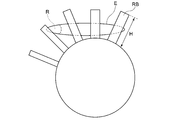
- the circumferential length L of the elliptical outlet opening E becomes longer, a part of the refrigerant flowing out of the flow path, specifically, the circumferential direction of the elliptical outlet opening becomes larger.
- the refrigerant R flowing out from the vicinity of the end cannot appropriately flow into the moving blade RB. To cope with this, as shown in FIG.
- At least one embodiment of the present disclosure has an object to provide a two-phase flow turbine nozzle capable of improving the performance of a two-phase flow turbine, and a two-phase flow turbine and a refrigeration cycle with improved performance. I do.
- a two-phase flow turbine nozzle includes: A two-phase turbine nozzle provided in a two-phase turbine driven by a gas-liquid two-phase flow of fluid,
- the two-phase flow turbine nozzle includes a plurality of stator vanes arranged in a circumferential direction so as to form a flow path therebetween.
- the outlet opening of the flow path has a shape in which the width in the radial direction is longer than the width in the circumferential direction.
- the outlet opening of the flow path has a shape in which the width in the radial direction is longer than the width in the circumferential direction
- the fluid flowing out from the vicinity of the end in the circumferential direction of the outlet opening also has Since the fluid flows into the moving blades of the two-phase flow turbine and most of the fluid flowing out of the outlet opening flows into the moving blade at an appropriate angle, the performance of the two-phase flow turbine can be improved.
- At least a part of the inner wall surface that defines the flow path is flat.
- the flow passage increases in cross-sectional area from the throat to the outlet opening.
- the cross-sectional area of the flow path decreases from the upstream side to the throat, and the cross-sectional area increases from the throat to the outlet opening.
- the flow path constitutes a Laval nozzle (tapered divergent nozzle) as a whole.
- the flow path has a radial width increasing from the throat toward the outlet opening.
- the flow path can be formed in a configuration in which the cross-sectional area increases from the throat to the outlet opening while the circumferential width decreases from the throat to the outlet opening.
- the two-phase turbine nozzle is formed by inserting the first block having the plurality of stationary blades into the insertion hole formed in the second block. The formation and assembly of the nozzle can be facilitated.
- the first block and the second block are provided such that an axial direction of each of the first block and the second block is along a vertical direction
- the vane is configured such that a distance from an axis center of the first block to a tip side edge of the vane decreases downward in a vertical direction
- the insertion hole is configured such that the cross-sectional area of the insertion hole decreases downward in the vertical direction
- the first block is inserted into the insertion hole such that the chip side edge contacts the inner peripheral surface of the insertion hole.
- the tip side edge of the stationary blade contacts the inner peripheral surface of the insertion hole due to the gravity of the first block, and the first block becomes the second block. Is fixed with a metal touch. Therefore, fixing work such as welding is not required for fixing the first block to the second block, so that formation and assembly of the two-phase flow turbine nozzle can be further facilitated.
- a force may be applied to the first block so that the first block rotates around its axial direction. According to the configuration of (7), even if such a force is applied to the first block, the rotation of the first block can be prevented by the rotation preventing member.
- the flow path has a cross-sectional shape in which the width in the circumferential direction increases from the radially inner side to the radially outer side.
- the two-phase flow turbine includes: A two-phase flow turbine nozzle according to any one of the above (1) to (8); A two-phase flow turbine rotor having moving blades provided to face the outlet opening, and driven by a gas-liquid two-phase flow of the refrigerant.
- a refrigeration cycle includes: An evaporator, A compressor, A condenser, And the two-phase flow turbine of (9).
- the outlet opening of the flow path has a shape in which the width in the radial direction is longer than the width in the circumferential direction.
- Refrigerant also flows into the rotor blades of the two-phase turbine, and most of the refrigerant flowing out of the outlet opening flows into the rotor blades at an appropriate angle, thereby improving the performance of the two-phase turbine.
- 1 is a configuration diagram of a refrigeration cycle according to an embodiment of the present disclosure.
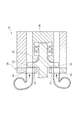
- 1 is an axial sectional view of a two-phase flow turbine according to an embodiment of the present disclosure.
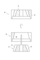
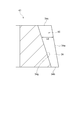
- 1 is a schematic meridional view of a two-phase flow turbine nozzle according to an embodiment of the present disclosure.
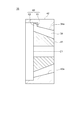
- FIG. 9 is a schematic meridian view of a modification of the two-phase flow turbine nozzle according to an embodiment of the present disclosure.
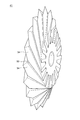
- 1 is a perspective view of a first block of a two-phase flow turbine nozzle according to an embodiment of the present disclosure.
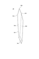
- 1 is a perspective view of one of a plurality of vanes formed in a first block of a two-phase flow turbine nozzle according to an embodiment of the present disclosure.
- FIG. 2 is a plan view of a first block of a two-phase flow turbine nozzle of a two-phase flow turbine provided in a refrigeration cycle according to an embodiment of the present disclosure.
- 1 is a schematic meridional view of a first block of a two-phase flow turbine nozzle of a two-phase flow turbine provided in a refrigeration cycle according to an embodiment of the present disclosure. It is a mimetic diagram for explaining operation which a refrigerant ejected from a two-phase flow turbine nozzle concerning one embodiment of the present disclosure flows into a rotor blade.
- FIG. 9 is a schematic meridian view of a modification of the two-phase flow turbine nozzle according to an embodiment of the present disclosure.
- a refrigeration cycle 10 includes a compressor 11 for compressing a refrigerant, a condenser 12 for condensing the compressed refrigerant, and a refrigerant 12 in a gas-liquid mixed state.
- a two-phase flow turbine (13) driven by a two-phase flow of a refrigerant having a wetness of 50% or more, and a refrigerant decompressed by the two-phase flow turbine 13
- an evaporator 14 for generating heat by the heat of vaporization of the refrigerant by exchanging heat with the evaporator 14 to cool the cooling water.
- the refrigeration cycle 10 is configured such that a refrigerant can be circulated by sequentially connecting a compressor 11, a condenser 12, a two-phase flow turbine 13, and an evaporator 14 through a refrigerant circulation path 15.
- the refrigeration cycle 10 can adopt several modified forms.
- the compressor 11 may be a multi-stage compressor.
- the compressor 11 includes a high-pressure compressor 11A and a low-pressure compressor 11B connected in series via a connection pipe 16, and includes a high-pressure compressor 11A and a low-pressure compressor.
- the side compressors 11B may be coaxially connected to each other and configured to be drivable by the electric motor 19.
- the modification regarding the refrigeration cycle 10 is not limited to such an embodiment, and can be adopted as long as the configuration of the present disclosure described below is not hindered.
- the two-phase turbine 13 has a rotating shaft 17, and a generator 18 is mechanically connected to the rotating shaft 17.
- the generator 18 is connected to a power storage device such as a battery that charges the electric energy generated by the generator 18 and a load that consumes the electric energy generated by the generator 18. You may.
- the two-phase flow turbine 13 includes a two-phase flow turbine rotor 33 having a plurality of moving blades 32 and a two-phase flow having a plurality of stationary blades 34 provided on the upstream side of the moving blade 32.
- a turbine nozzle 35 and a two-phase turbine diffuser 36 are provided.
- the two-phase flow turbine nozzle 35 includes a first block 41 having a plurality of stationary blades 34 formed therein, and a cylindrical second block 42 having an insertion hole 43 formed therein.
- the first block 41 is inserted into the hole 43.
- the two-phase turbine nozzle 35 is formed by inserting the first block 41 having the plurality of stationary blades 34 into the insertion hole 43 formed in the second block 42, so that the two-phase turbine nozzle 35 is formed. The formation and assembly of the flow turbine nozzle 35 can be facilitated.
- the first block 41 and the second block 42 are provided so that the axial direction of each of the first block 41 and the second block 42 is along the vertical direction.
- the stationary blade 34 is configured such that the distance L1 to the tip side edge 34a of the blade 34 decreases vertically downward, so that the inner diameter of the insertion hole 43, that is, the cross-sectional area S1 decreases vertically downward.
- the insertion hole 43 may be formed in a truncated cone shape.
- the first block 41 can be inserted into the insertion hole 43 such that the chip side edge 34a contacts the inner peripheral surface 43a of the insertion hole 43.
- the tip side edge 34 a of the stationary blade 34 contacts the inner peripheral surface 43 a of the insertion hole 43 due to the gravity of the first block 41, and the first block 41 is moved to the second block. 42 is fixed by metal touch.
- the first block 41 is pressed against the second block 42 also by the differential pressure of the refrigerant when the refrigerant flows through the two-phase flow turbine nozzle 35. Therefore, fixing work such as welding is not required for fixing the first block 41 to the second block 42, so that the formation and assembly of the two-phase flow turbine nozzle 35 can be further facilitated.
- the first block 41 has a substantially frustoconical overall shape by machining a plurality of stationary blades 34 so as to be arranged in the circumferential direction.
- FIG. 6 shows a perspective view of one of the plurality of stationary blades 34.
- Each vane 34 has a shape in which the thickness gradually increases from the leading edge 34b toward the trailing edge 34c, reaches a maximum at the portion 34d, and then decreases toward the trailing edge 34c. are doing. This shape can be easily understood from the shape of the tip side edge 34a of the stationary blade 34.
- the stationary blade 34 further has a first surface 34e extending from the portion 34d to the trailing edge 34c and connected to the chip side edge 34a, and a second surface 34f facing the first surface 34e, and the second surface 34f is also a second surface 34f. Like the one surface 34e, it extends from the portion 34d to the rear edge 34c and is connected to the chip side edge 34a.
- a gap is formed between the first surface 34e of each stationary blade 34 and the second surface 34f of another stationary blade adjacent to each stationary blade 34 in the circumferential direction. As shown in FIG. 7, this gap forms a flow path 50 through which the refrigerant flows in an operation described later.
- Each flow path 50 is formed between the stationary blades 34 adjacent to each other in the circumferential direction, and opens at the circular end face 41 a of the first block 41. That is, the outlet opening 51 of each flow path 50 is formed in the end face 41a.
- the outlet opening 51 of the two-phase turbine nozzle 35 faces the moving blade 32 of the two-phase turbine rotor 33.
- the outlet opening 51 has a shape in which the length L2 of the radially inner edge 51a of the outlet opening 51 is shorter than the length L3 of the radially outer edge 51b of the outlet opening 51. are doing. For this reason, a configuration is possible in which the outlet openings 51 of the respective flow paths 50 are arranged in the end face 41a in a circumferential shape while keeping the interval between them as short as possible.
- the cross-sectional shape at an arbitrary position of the flow path 50 is also a shape in which the length of the radially inner edge is shorter than the length of the radially outer edge, similarly to the shape where L2 ⁇ L3 at the outlet opening 51. have.
- the flow path 50 has a cross-sectional shape in which the width in the circumferential direction increases from the radial inside to the radial outside.
- the outlet opening 51 has a shape in which the width L4 in the radial direction is longer than the width L5 in the circumferential direction (L2 ⁇ L5 ⁇ L3).
- each flow path 50 is formed so that the width in the circumferential direction increases from the upstream side to the downstream side.
- the stationary blade 34 has a length from the hub side edge 34g to the tip side edge 34a of the stationary blade 34 from the leading edge 34b toward the trailing edge 34c, that is, the stationary blade 34 The blade height is increased.
- each flow path 50 is moved from the upstream side to the downstream side.
- the width in the circumferential direction decreases toward, the cross-sectional area increases from the upstream side to the downstream side.
- each flow path 50 has a minimum cross-sectional area at the portion 34 d of the stationary blade 34, so that the throat 52 of the flow path 50 is formed at the portion 34 d. Therefore, although not shown in FIG. 7, each flow path 50 can have a configuration in which the cross-sectional area decreases from the upstream side to the throat 52 and the cross-sectional area increases from the throat 52 to the outlet opening 51. When each flow path 50 has such a configuration, each flow path 50 forms a Laval nozzle (tapered divergent nozzle) as a whole.
- Laval nozzle tapeered divergent nozzle
- the first surface 34e and the second surface 34f of the stationary blade 34 are respectively flat.
- at least a part of the inner wall surface defining the flow path 50 has a flat configuration. According to this configuration, since at least a part of the inner wall surface that defines the flow path 50 is flat, the workability of the flat part is improved, and therefore, the first block 41 of the two-phase flow turbine nozzle 35 (see FIG. 2). Can be improved in machining when machining.
- the flow path 50 has a cross-sectional shape in which the width in the circumferential direction increases from the radial inner side to the radial outer side is also advantageous.
- the flow path 50 has such a configuration, when forming the flow path 50 by machining, one side of the first block 41 is pressed by pushing a machining tool from the radial outside to the radial inside of the first block 41. Can be machined from the end face 41a of the first to the other end face, so that workability can be improved.
- the high-pressure side compressor 11A and the low-pressure side compressor 11B driven by the electric motor 19 compress the gaseous refrigerant, so that the refrigerant circulates through the refrigeration cycle 10.
- the compressed refrigerant flows into the condenser 12 through the refrigerant circulation path 15 and is condensed by the condenser 12 to become a liquid.
- the refrigerant flowing out of the two-phase flow turbine 13 cools the cooling water by exchanging heat with the cooling water in the evaporator 14.
- the refrigerant flowing out of the evaporator 14 flows into the low-pressure side compressor 11B and is compressed, then flows through the connection pipe 16, flows into the high-pressure side compressor 11A, and is further compressed.
- the refrigerant flowing into the two-phase turbine 13 flows into the two-phase turbine nozzle 35.
- the refrigerant that has flowed into the two-phase flow turbine nozzle 35 flows through the flow path 50 (see FIG. 5 or 7) and is ejected from the outlet opening 51, and is then supplied to the moving blade 32.
- the refrigerant flows through the flow path 50, the refrigerant is flushed at the throat 52 of the flow path 50 (see FIG. 7), so that the refrigerant becomes a gas-liquid two-phase flow.
- a gas-liquid two-phase flow contains droplets in a gas. Since the weight of the droplet is larger than that of the gas, the flow velocity of the droplet is smaller than the flow velocity of the gas.
- the droplets are accelerated from the throat 52 to the outlet opening 51 by high-speed gas existing around.
- a gas-liquid two-phase flow including the accelerated droplets is jetted toward the bucket 32.
- the gas-liquid two-phase flow ejected from the outlet opening 51 drives the moving blade 32, and at this time, accelerated droplets mainly contained in the gas-liquid two-phase flow give kinetic energy to the moving blade 32. It will be.
- the gas-liquid two-phase flow of the refrigerant ejected from the two-phase turbine nozzle 35 is supplied to the moving blade 32 to rotate the two-phase turbine rotor 33, so that the two-phase turbine 13 is driven. You.
- the refrigerant that has driven the two-phase turbine 13 flows out of the two-phase turbine 13 through the two-phase turbine diffuser 36.
- the flow path 50 has a Laval nozzle (tapered divergent nozzle) configuration as a whole, the flow path 50 has a shape corresponding to the volume expansion of the refrigerant flowing out of the two-phase flow turbine nozzle 35.
- the energy given to the rotor blades 32 by the refrigerant is increased as compared with the case where no flow path is employed, and the performance of the two-phase flow turbine 13 can be improved.
- the outlet opening 51 of the flow path 50 has a shape in which the radial width L4 is longer than the circumferential width L5. Then, as shown in FIG. 9, the refrigerant spread from each outlet opening 51 in the circumferential direction becomes smaller than the radial spread of the refrigerant, and the refrigerant flowing out from the vicinity of the circumferential end of the outlet opening 51. Since the refrigerant also flows into the moving blade 32, it is more appropriate for the moving blade 32 than in the case where the circumferential spread of the refrigerant is large (for example, in the case of an elliptical shape long in the circumferential direction as shown in FIG. 11A). Refrigerant that cannot flow can be reduced.
- the outlet opening 51 of the flow path 50 has a shape in which the radial width L4 is longer than the circumferential width L5
- the refrigerant flowing out from the vicinity of the circumferential end of the outlet opening 51 also has Since the refrigerant flows into the moving blades 32 of the two-phase flow turbine 13 and most of the refrigerant flowing out of the outlet opening 51 flows into the moving blades 32 at an appropriate angle, the performance of the two-phase flow turbine 13 is improved. can do.
- each flow path 50 is such that its longitudinal direction is offset from the axial center C1 of the first block 41 (that is, the longitudinal extension of each flow path 50 passes through the axial center C1). No) configuration. For this reason, when the refrigerant flows through each flow path 50, a force that rotates the first block 41 about the axial center C1 in the insertion hole 43 (see FIG. 3) of the second block 42 (see FIG. 3). Is supplied to the first block 41 by the refrigerant. In order to suppress the rotation of the first block 41 due to such a force, for example, as shown in FIG.
- a protruding portion 62 (the first protruding portion 62) protruding radially outward from the tip side edge 34 a of the stationary blade 34. 1) and a slit portion 61 (second portion) which is opened in the inner peripheral surface 43a of the insertion hole 43 and in which the protruding portion 62 is insertable. 35 may be provided. Even if a force for rotating the first block 41 about the axis center C1 is applied to the first block 41, since the protruding portion 62 is inserted into the slit portion 61, the inside of the slit portion 61 is defined. When the protruding portion 62 abuts on the wall surface, the first block 41 cannot rotate further from that state.
- the rotation preventing member 60 is not limited to the above-described form of the slit portion 61 and the protruding portion 62, and a force that rotates the first block 41 about the axis center C1 is applied to the first block 41. Any structure may be used as long as the first portion and the second portion are configured so as to be able to abut against each other in the circumferential direction when added to 41.
- the number of the rotation preventing members 60 is not limited to one for one two-phase flow turbine nozzle 35, and an arbitrary number may be provided.
Landscapes
- Engineering & Computer Science (AREA)
- Mechanical Engineering (AREA)
- General Engineering & Computer Science (AREA)
- Chemical & Material Sciences (AREA)
- Combustion & Propulsion (AREA)
- Physics & Mathematics (AREA)
- Thermal Sciences (AREA)
- Turbine Rotor Nozzle Sealing (AREA)
- Engine Equipment That Uses Special Cycles (AREA)
Abstract
流体の気液二相流によって駆動される二相流タービンに設けられた二相流タービンノズルは、互いの間に流路を形成するように周方向に配列された複数の静翼を備え、流路の出口開口は、周方向の幅よりも径方向の幅の方が長い形状を有する。
Description
本開示は、二相流タービンノズル及びこの二相流タービンノズルを備える二相流タービン並びにこの二相流タービンを備える冷凍サイクルに関する。
圧縮機、凝縮器、膨張手段、及び蒸発器を順次配管で接続して冷媒が循環可能に構成され、膨張手段として二相流タービンを用いた冷凍サイクルが、例えば特許文献1に記載されている。このような二相流タービンにおけるタービンノズルが特許文献2に記載されている。このタービンノズルにおいて冷媒が流れる流路は、円筒形状のノズルブロックに外周面から内周面にかけて円柱形状の穴を加工することにより形成されている。
しかしながら、特許文献2に記載のタービンノズルでは、冷媒が流れる流路の出口開口は一般的に、ノズルブロックの周方向に長い楕円形状を有するようになる。図11Aに示されるように、楕円形状の出口開口Eの周方向の長さLが長くなればなるほど、流路から流出する冷媒の一部、具体的には、楕円形状の出口開口の周方向における端部付近から流出する冷媒Rが動翼RBに適切に流入できなくなってしまう。これに対処するためには、図11Bに示されるように、動翼RBの翼高さHを大きくすれば、楕円形状の出口開口Eの周方向における端部付近から流出する冷媒Rも動翼RBに流入するようになるが、動翼RBに適切な角度で流入する冷媒が増えるわけではない。その結果、図11A及び図11Bのいずれの場合でも、二相流タービンの性能が低下してしまうといった問題点があった。
上述の事情に鑑みて、本開示の少なくとも1つの実施形態は、二相流タービンの性能を向上できる二相流タービンノズル並びに性能を向上した二相流タービン及び冷凍サイクルを提供することを目的とする。
(1)本発明の少なくとも1つの実施形態に係る二相流タービンノズルは、
流体の気液二相流によって駆動される二相流タービンに設けられた二相流タービンノズルであって、
前記二相流タービンノズルは、互いの間に流路を形成するように周方向に配列された複数の静翼を備え、
前記流路の出口開口は、周方向の幅よりも径方向の幅の方が長い形状を有する。
流体の気液二相流によって駆動される二相流タービンに設けられた二相流タービンノズルであって、
前記二相流タービンノズルは、互いの間に流路を形成するように周方向に配列された複数の静翼を備え、
前記流路の出口開口は、周方向の幅よりも径方向の幅の方が長い形状を有する。
上記(1)の構成によると、流路の出口開口が周方向の幅よりも径方向の幅の方が長い形状を有することにより、出口開口の周方向における端部付近から流出する流体も、二相流タービンの動翼に流入するようになり、出口開口から流出する流体の多くが適切な角度で動翼に流入するようになるので、二相流タービンの性能を向上することができる。
(2)いくつかの実施形態では、上記(1)の構成において、
前記流路を画定する内壁面の少なくとも一部は平坦である。
前記流路を画定する内壁面の少なくとも一部は平坦である。
タービンノズルを機械加工する際に、流路の形状が円筒形状である場合よりも流路の断面が矩形形状である場合の方が加工性は良い。上記(2)の構成によると、流路を画定する内壁面の少なくとも一部が平坦であることにより、平坦部分の加工性は向上するので、タービンノズルを機械加工する際の加工性を向上することができる。
(3)いくつかの実施形態では、上記(1)または(2)の構成において、
前記流路は、スロートから前記出口開口に向かって断面積が増加する。
前記流路は、スロートから前記出口開口に向かって断面積が増加する。
上記(3)の構成によると、流路は、上流側からスロートまで断面積が減少し、スロートから出口開口まで断面積が増加するので、全体としてラバールノズル(先細末広ノズル)を構成する。これにより、二相流タービンノズルから流出する流体の体積膨張に見合った形状になるので、ラバールノズルの形態の流路を採用しない場合に比べて、流体が動翼に与えるエネルギーを増加し、二相流タービンの性能を向上することができる。
(4)いくつかの実施形態では、上記(3)の構成において、
前記流路は、前記スロートから前記出口開口に向かって径方向の幅が増加する。
前記流路は、前記スロートから前記出口開口に向かって径方向の幅が増加する。
上記(4)の構成によると、スロートから出口開口に向かって周方向の幅が減少しながらスロートから出口開口まで断面積が増加する構成に流路を形成することができる。これにより、上記(1)による効果及び上記(3)による効果の両方を得ることができる。
(5)いくつかの実施形態では、上記(1)~(4)のいずれかの構成において、
前記複数の静翼が形成された第1ブロックと、
前記第1ブロックが挿入可能に構成された挿入穴が形成された第2ブロックと
を備え、
前記第1ブロックが前記挿入穴内に挿入されている。
前記複数の静翼が形成された第1ブロックと、
前記第1ブロックが挿入可能に構成された挿入穴が形成された第2ブロックと
を備え、
前記第1ブロックが前記挿入穴内に挿入されている。
上記(5)の構成によると、複数の静翼を形成した第1ブロックを、第2ブロックに形成された挿入穴内に挿入することで二相流タービンノズルが形成されるので、二相流タービンノズルの形成・組み立てを容易にすることができる。
(6)いくつかの実施形態では、上記(5)の構成において、
前記第1ブロック及び前記第2ブロックそれぞれの軸方向が鉛直方向に沿うように前記第1ブロック及び前記第2ブロックが設けられ、
前記第1ブロックの軸中心から前記静翼のチップ側縁までの距離が鉛直方向下側に向かって減少するように前記静翼は構成され、
前記挿入穴の断面積が鉛直方向下側に向かって減少するように前記挿入穴は構成され、
前記挿入穴の内周面に前記チップ側縁が接触するように前記第1ブロックは前記挿入穴内に挿入されている。
前記第1ブロック及び前記第2ブロックそれぞれの軸方向が鉛直方向に沿うように前記第1ブロック及び前記第2ブロックが設けられ、
前記第1ブロックの軸中心から前記静翼のチップ側縁までの距離が鉛直方向下側に向かって減少するように前記静翼は構成され、
前記挿入穴の断面積が鉛直方向下側に向かって減少するように前記挿入穴は構成され、
前記挿入穴の内周面に前記チップ側縁が接触するように前記第1ブロックは前記挿入穴内に挿入されている。
上記(6)の構成によると、第1ブロックを挿入穴内に挿入すると、第1ブロックの重力によって静翼のチップ側縁が挿入穴の内周面に接触して、第1ブロックが第2ブロックに対してメタルタッチ固定される。このため、第1ブロックの第2ブロックへの固定に溶接等の固定作業が不要になるので、二相流タービンノズルの形成・組み立てをさらに容易にすることができる。
(7)いくつかの実施形態では、上記(5)または(6)の構成において、
前記第1ブロック又は前記第2ブロックの少なくとも一方に設けられた第1部分と、
前記第1ブロック又は前記第2ブロックの他方に設けられた第2部分と
を含む回転防止部材をさらに備え、
前記挿入穴内において前記第1ブロックに該第1ブロックの軸中心を中心とした周方向の力が加えられたときに、前記第1部分と前記第2部分とが互いに対して前記周方向に当接可能に構成されている。
前記第1ブロック又は前記第2ブロックの少なくとも一方に設けられた第1部分と、
前記第1ブロック又は前記第2ブロックの他方に設けられた第2部分と
を含む回転防止部材をさらに備え、
前記挿入穴内において前記第1ブロックに該第1ブロックの軸中心を中心とした周方向の力が加えられたときに、前記第1部分と前記第2部分とが互いに対して前記周方向に当接可能に構成されている。
流路を流体が流れる際に、第1ブロックがその軸方向を中心に回転するような力が第1ブロックに加わる場合がある。上記(7)の構成によると、第1ブロックにこのような力が加わったとしても、回転防止部材によって第1ブロックの回転を防止するができる。
(8)いくつかの実施形態では、上記(1)~(7)のいずれかの構成において、
前記流路は、径方向内側から径方向外側に向かって周方向の幅が増加する断面形状を有する。
前記流路は、径方向内側から径方向外側に向かって周方向の幅が増加する断面形状を有する。
上記(8)の構成によると、流路を機械加工で形成する際、第1ブロックの径方向外側から径方向内側へ機械加工工具を押し込むようにして第1ブロックの一方の端面から他方の端面に向かって加工できるので、加工性を向上することができる。
(9)本発明の少なくとも1つの実施形態に係る二相流タービンは、
上記(1)~(8)のいずれかの二相流タービンノズルと、
前記出口開口に対向するように設けられる動翼を備えた二相流タービンロータと
を備え、冷媒の気液二相流によって駆動される。
上記(1)~(8)のいずれかの二相流タービンノズルと、
前記出口開口に対向するように設けられる動翼を備えた二相流タービンロータと
を備え、冷媒の気液二相流によって駆動される。
上記(9)の構成によると、性能を向上した二相流タービンを実現できる。
(10)本発明の少なくとも1つの実施形態に係る冷凍サイクルは、
蒸発器と、
圧縮機と、
凝縮器と、
上記(9)の二相流タービンと
を備える。
蒸発器と、
圧縮機と、
凝縮器と、
上記(9)の二相流タービンと
を備える。
上記(10)の構成によると、性能を向上した冷凍サイクルを実現できる。
本開示の少なくとも1つの実施形態によれば、流路の出口開口が周方向の幅よりも径方向の幅の方が長い形状を有することにより、出口開口の周方向における端部付近から流出する冷媒も、二相流タービンの動翼に流入するようになり、出口開口から流出する冷媒の多くが適切な角度で動翼に流入するようになるので、二相流タービンの性能を向上することができる。
以下、図面を参照して本発明のいくつかの実施形態について説明する。ただし、本発明の範囲は以下の実施形態に限定されるものではない。以下の実施形態に記載されている構成部品の寸法、材質、形状、その相対配置などは、本発明の範囲をそれにのみ限定する趣旨ではなく、単なる説明例に過ぎない。
図1に示されるように、本開示の一実施形態に係る冷凍サイクル10は、冷媒を圧縮する圧縮機11と、圧縮された冷媒を凝縮する凝縮器12と、気液混合状態の冷媒の二相流(気液二相流)、厳密に言えば湿り度が50%以上の冷媒の二相流によって駆動される二相流タービン13と、二相流タービン13によって減圧された冷媒を冷却水と熱交換することにより、冷媒の気化熱による冷熱を発生させることで冷却水を冷却する蒸発器14とを備えている。冷凍サイクル10は、圧縮機11と凝縮器12と二相流タービン13と蒸発器14とが冷媒循環経路15で順次接続されることにより、冷媒が循環可能に構成されている。
冷凍サイクル10は、いくつかの変形形態を採用することができる。例えば、圧縮機11は多段型の圧縮機でもよく、例えば、接続配管16を介して互いに直列的に接続された高圧側圧縮機11A及び低圧側圧縮機11Bを含み、高圧側圧縮機11A及び低圧側圧縮機11Bは互いに同軸上に連結され、電動機19によって駆動可能に構成されてもよい。尚、冷凍サイクル10に関する変形形態はこのような形態に限定するものではなく、以下で説明する本開示の構成を妨げるものでない限り採用可能である。
二相流タービン13は回転軸17を有し、回転軸17には発電機18が機械的に連結されている。図1には図示されていないが、発電機18は、発電機18によって生成された電気エネルギーを充電するバッテリー等の蓄電装置や、発電機18によって生成された電気エネルギーを消費する負荷に接続されてもよい。
図2に示されるように、二相流タービン13は、複数の動翼32を有する二相流タービンロータ33と、動翼32の上流側に設けられた複数の静翼34を有する二相流タービンノズル35と、二相流タービンディフューザー36とを備えている。
図3に示されるように、二相流タービンノズル35は、複数の静翼34が形成された第1ブロック41と、挿入穴43が形成された筒形状の第2ブロック42とを備え、挿入穴43内に第1ブロック41が挿入されている。この構成によると、複数の静翼34を形成した第1ブロック41を、第2ブロック42に形成された挿入穴43内に挿入することで二相流タービンノズル35が形成されるので、二相流タービンノズル35の形成・組み立てを容易にすることができる。
図4に示されるように、第1ブロック41及び第2ブロック42それぞれの軸方向が鉛直方向に沿うように第1ブロック41及び第2ブロック42を設け、第1ブロック41の軸中心C1から静翼34のチップ側縁34aまでの距離L1が鉛直方向下側に向かって減少するように静翼34を構成し、挿入穴43の内径すなわち断面積S1が鉛直方向下側に向かって減少するように挿入穴43を円錐台形状に構成してもよい。
この構成によると、挿入穴43の内周面43aにチップ側縁34aが接触するように第1ブロック41を挿入穴43内に挿入することができる。第1ブロック41を挿入穴43内に挿入すると、第1ブロック41の重力によって静翼34のチップ側縁34aが挿入穴43の内周面43aに接触して、第1ブロック41が第2ブロック42に対してメタルタッチ固定される。また、冷媒が二相流タービンノズル35を流通する際の冷媒の差圧によっても第1ブロック41が第2ブロック42に対して押し付けられるようになる。このため、第1ブロック41の第2ブロック42への固定に溶接等の固定作業が不要になるので、二相流タービンノズル35の形成・組み立てをさらに容易にすることができる。
図5に示されるように、第1ブロック41は、周方向に配列されるように複数の静翼34が機械加工されることにより、略円錐台形状の全体形状を有している。これら複数の静翼34のうちの1つの斜視図を図6に示す。各静翼34は、前縁34bから後縁34cに向かって厚さが徐々に増加して部分34dで厚さが最大になった後、後縁34cに向かって厚さが減少する形状を有している。この形状は、静翼34のチップ側縁34aの形状から容易に理解することができる。静翼34はさらに、部分34dから後縁34cまで延びるとともにチップ側縁34aに接続する第1面34eと、第1面34eと対向する第2面34fとを有し、第2面34fも第1面34eと同様に、部分34dから後縁34cまで延びるとともにチップ側縁34aに接続している。
各静翼34の第1面34eと、各静翼34と周方向に隣り合う他の静翼の第2面34fとの間には隙間が形成されている。図7に示されるように、この隙間は、後述する動作で冷媒が流通する流路50を構成する。各流路50は、周方向に隣り合う静翼34,34間に形成され、第1ブロック41の円形状の端面41aにおいて開口している。すなわち、端面41aには、各流路50の出口開口51が形成されている。図2に示されるように、二相流タービン13において、二相流タービンノズル35の出口開口51は、二相流タービンロータ33の動翼32に対向する。
図7に示されるように、出口開口51は、出口開口51の径方向内側の縁部51aの長さL2が出口開口51の径方向外側の縁部51bの長さL3よりも短い形状を有している。このため、端面41aにおいて各流路50の出口開口51を互いの間隔をできる限り短くしながら円周形状に配置した構成が可能になる。尚、流路50の任意の位置における断面形状も、出口開口51においてL2<L3となる形状と同様に、径方向内側の縁部の長さが径方向外側の縁部の長さよりも短い形状を有している。すなわち、流路50は、径方向内側から径方向外側に向かって周方向の幅が増加する断面形状を有している。また、出口開口51は、周方向の幅L5(L2≦L5≦L3)よりも径方向の幅L4の方が長い形状を有している。
周方向に隣り合う静翼34,34間の間隔は、静翼34の前縁34b側から後縁34c側に向かって減少するように構成されている。したがって、各流路50は、上流側から下流側に向かって、周方向の幅が増加するように形成されている。一方で、図8に示されるように、静翼34は、前縁34bから後縁34cに向かって、静翼34のハブ側縁34gからチップ側縁34a間の長さ、すなわち静翼34の翼高さが増加するように形成されている。静翼34のこのような構成により、各流路50は、上流側から下流側に向かって、径方向の幅L6が増加するように形成されている。上流側から下流側に向かう各流路50の周方向の幅の減少率よりも各流路50の径方向の幅の増加率を大きくすることにより、各流路50は、上流側から下流側に向かって周方向の幅が短くなるにもかかわらず、上流側から下流側に向かって断面積が増加する構成を有することができる。
この場合、図7に示されるように、各流路50は、静翼34の部分34dにおいて断面積が最小となるので、部分34dにおいて流路50のスロート52が形成される。したがって、各流路50は、図7には図示されていないが上流側からスロート52まで断面積が減少し、スロート52から出口開口51まで断面積が増加する構成を有することができる。各流路50がこのような構成を有する場合、各流路50は全体としてラバールノズル(先細末広ノズル)を構成することになる。
図6に示されるように、静翼34の第1面34e及び第2面34fはそれぞれ平坦であることが好ましい。この場合、流路50(図5又は7参照)を画定する内壁面の少なくとも一部が平坦な構成となる。この構成によると、流路50を画定する内壁面の少なくとも一部が平坦であることにより、平坦部分の加工性は向上するので、二相流タービンノズル35(図2参照)の第1ブロック41を機械加工する際の加工性を向上することができる。
図7に示されるように、第1ブロック41を機械加工で作成する場合、径方向内側から径方向外側に向かって周方向の幅が増加する断面形状を流路50が有する構成も有利になる。流路50がこのような構成を有する場合、流路50を機械加工で形成する際、第1ブロック41の径方向外側から径方向内側へ機械加工工具を押し込むようにして第1ブロック41の一方の端面41aから他方の端面に向かって加工できるので、加工性を向上することができる。
次に、本開示の一実施形態に係る冷凍サイクル10の動作について説明する。
図1に示されるように、電動機19によって駆動される高圧側圧縮機11A及び低圧側圧縮機11Bが気体状態の冷媒を圧縮することによって、冷凍サイクル10を冷媒が循環する。圧縮された冷媒は、冷媒循環経路15を流通して凝縮器12に流入し、凝縮器12によって凝縮されて液体となる。
凝縮器12から流出して冷媒循環経路15を流通する液体の冷媒は、二相流タービン13に流入して、後述する動作で二相流タービン13を駆動する。冷媒によって駆動された二相流タービン13の動力を、回転軸17を介して発電機18に伝達することによって発電機18を駆動し、発電を行う。発電された電気エネルギーは、図示しない蓄電装置に充電されたり、図示しない負荷において消費されたりすることができる。
二相流タービン13から流出した冷媒は、蒸発器14において冷却水と熱交換することにより冷却水を冷却する。蒸発器14から流出した冷媒は、低圧側圧縮機11Bに流入して圧縮された後、接続配管16を流通し、高圧側圧縮機11Aに流入してさらに圧縮される。
図2に示されるように、二相流タービン13に流入した冷媒は、二相流タービンノズル35に流入する。二相流タービンノズル35に流入した冷媒は、流路50(図5又は7参照)を流通して出口開口51から噴出した後、動翼32に供給される。冷媒が流路50を流通する際、冷媒は、流路50のスロート52(図7参照)においてフラッシュされることにより、気液二相流となる。気液二相流は、気体中に液滴を含んでいる。液滴は気体に比べて重量が大きいため、液滴の流速は気体の流速に比べて小さくなる。液滴は、スロート52から出口開口51にかけて、周囲に存在する高速な気体によって加速される。出口開口51では、加速された液滴を含む気液二相流が動翼32に向けて噴出される。出口開口51から噴出された気液二相流は、動翼32を駆動するが、このとき主に気液二相流に含まれる加速された液滴が動翼32に対して運動エネルギーを与えることとなる。
このようにして、二相流タービンノズル35から噴出された冷媒の気液二相流が動翼32に供給されて二相流タービンロータ33を回転することで、二相流タービン13が駆動される。二相流タービン13を駆動した冷媒は、二相流タービンディフューザー36を流通して二相流タービン13から流出する。
上述したように流路50が全体としてラバールノズル(先細末広ノズル)の構成を有している場合、二相流タービンノズル35から流出する冷媒の体積膨張に見合った形状になるので、ラバールノズルの形態の流路を採用しない場合に比べて、冷媒が動翼32に与えるエネルギーを増加し、二相流タービン13の性能を向上することができる。
また、図7に示されるように、流路50の出口開口51は、周方向の幅L5よりも径方向の幅L4の方が長い形状を有している。そうすると、図9に示されるように、各出口開口51から噴出される冷媒の周方向の広がりが冷媒の径方向の広がりよりも小さくなり、出口開口51の周方向における端部付近から流出する冷媒も動翼32に流入するようになるので、冷媒の周方向の広がりが大きい場合(例えば図11Aに示されるような、周方向に長い楕円形状の場合)に比べて、動翼32に適切に流入できない冷媒を低減することができる。さらに、出口開口51から流出する冷媒の多くが適切な角度で動翼32に流入するようになるので、二相流タービン13(図1参照)の性能を向上することができる。このような構成によれば、図11Bに示されるように動翼の翼高さを大きくする必要もなくなる。
このように、流路50の出口開口51が周方向の幅L5よりも径方向の幅L4の方が長い形状を有することにより、出口開口51の周方向における端部付近から流出する冷媒も、二相流タービン13の動翼32に流入するようになり、出口開口51から流出する冷媒の多くが適切な角度で動翼32に流入するようになるので、二相流タービン13の性能を向上することができる。
図7に示されるように、各流路50は、その長手方向が第1ブロック41の軸中心C1からオフセットするような(すなわち、各流路50の長手方向の延長線が軸中心C1を通らない)構成となっている。このため、各流路50を冷媒が流通する際、第1ブロック41を第2ブロック42(図3参照)の挿入穴43(図3参照)内において軸中心C1を中心に回転させるような力を冷媒が第1ブロック41に与える。このような力によって第1ブロック41が回転するのを抑制するために、例えば図10に示されるように、静翼34のチップ側縁34aから径方向外側に向かって突出する突出部62(第1部分)と、挿入穴43の内周面43aに開口するとともに突出部62が挿入可能に形成されたスリット部61(第2部分)とから構成される回転防止部材60を二相流タービンノズル35に設けてもよい。軸中心C1を中心に第1ブロック41を回転させるような力が第1ブロック41に加えられたとしても、スリット部61内に突出部62が挿入されているので、スリット部61を画定する内壁面に突出部62が当接することにより、その状態からさらに第1ブロック41が回転することができなくなる。
尚、回転防止部材60は、上記のようなスリット部61及び突出部62のような形態に限定するものではなく、軸中心C1を中心に第1ブロック41を回転させるような力が第1ブロック41に加えられたときに、第1部分と第2部分とが互いに対して周方向に当接可能に構成されたものであればどのようなものであってもよい。また、回転防止部材60は、1つの二相流タービンノズル35に対して1つだけに限定するものではなく、任意の個数設けてもよい。
10 冷凍サイクル
11 圧縮機
11A 高圧側圧縮機
11B 低圧側圧縮機
12 凝縮器
13 二相流タービン
14 蒸発器
15 冷媒循環経路
16 接続配管
17 回転軸17
18 発電機
19 電動機
32 動翼
33 二相流タービンロータ
34 静翼
34a (静翼の)チップ側縁
34b (静翼の)前縁
34c (静翼の)後縁
34d (静翼の)部分
34e (静翼の)第1面
34f (静翼の)第2面
34g (静翼の)ハブ側縁
35 二相流タービンノズル
36 タービンディフューザー
41 第1ブロック
41a (第1ブロックの)端面
42 第2ブロック
43 挿入穴
43a (挿入穴の)内周面
50 流路
51 出口開口
51a (出口開口の)径方向内側の縁部
51b (出口開口の)径方向外側の縁部
52 スロート
60 回転防止部材
61 スリット部(第2部分)
62 突出部(第1部分)
C1 (第1ブロックの)軸中心
L1 第1ブロックの軸中心から静翼のチップ側縁までの距離
L2 出口開口の径方向内側の縁部の長さ
L3 出口開口の径方向外側の縁部の長さ
L4 出口開口の径方向の長さ
L5 出口開口の周方向の幅
L6 流路の径方向の幅の
S1 挿入穴の断面積
11 圧縮機
11A 高圧側圧縮機
11B 低圧側圧縮機
12 凝縮器
13 二相流タービン
14 蒸発器
15 冷媒循環経路
16 接続配管
17 回転軸17
18 発電機
19 電動機
32 動翼
33 二相流タービンロータ
34 静翼
34a (静翼の)チップ側縁
34b (静翼の)前縁
34c (静翼の)後縁
34d (静翼の)部分
34e (静翼の)第1面
34f (静翼の)第2面
34g (静翼の)ハブ側縁
35 二相流タービンノズル
36 タービンディフューザー
41 第1ブロック
41a (第1ブロックの)端面
42 第2ブロック
43 挿入穴
43a (挿入穴の)内周面
50 流路
51 出口開口
51a (出口開口の)径方向内側の縁部
51b (出口開口の)径方向外側の縁部
52 スロート
60 回転防止部材
61 スリット部(第2部分)
62 突出部(第1部分)
C1 (第1ブロックの)軸中心
L1 第1ブロックの軸中心から静翼のチップ側縁までの距離
L2 出口開口の径方向内側の縁部の長さ
L3 出口開口の径方向外側の縁部の長さ
L4 出口開口の径方向の長さ
L5 出口開口の周方向の幅
L6 流路の径方向の幅の
S1 挿入穴の断面積
Claims (10)
- 流体の気液二相流によって駆動される二相流タービンに設けられた二相流タービンノズルであって、
前記二相流タービンノズルは、互いの間に流路を形成するように周方向に配列された複数の静翼を備え、
前記流路の出口開口は、周方向の幅よりも径方向の幅の方が長い形状を有する二相流タービンノズル。 - 前記流路を画定する内壁面の少なくとも一部は平坦である、請求項1に記載の二相流タービンノズル。
- 前記流路は、スロートから前記出口開口に向かって断面積が増加する、請求項1または2に記載の二相流タービンノズル。
- 前記流路は、前記スロートから前記出口開口に向かって径方向の幅が増加する、請求項3に記載の二相流タービンノズル。
- 前記複数の静翼が形成された第1ブロックと、
前記第1ブロックが挿入可能に構成された挿入穴が形成された第2ブロックと
を備え、
前記第1ブロックが前記挿入穴内に挿入されている、請求項1~4のいずれか一項に記載の二相流タービンノズル。 - 前記第1ブロック及び前記第2ブロックそれぞれの軸方向が鉛直方向に沿うように前記第1ブロック及び前記第2ブロックが設けられ、
前記第1ブロックの軸中心から前記静翼のチップ側縁までの距離が鉛直方向下側に向かって減少するように前記静翼は構成され、
前記挿入穴の断面積が鉛直方向下側に向かって減少するように前記挿入穴は構成され、
前記挿入穴の内周面に前記チップ側縁が接触するように前記第1ブロックは前記挿入穴内に挿入されている、請求項5に記載の二相流タービンノズル。 - 前記第1ブロック又は前記第2ブロックの少なくとも一方に設けられた第1部分と、
前記第1ブロック又は前記第2ブロックの他方に設けられた第2部分と
を含む回転防止部材をさらに備え、
前記挿入穴内において前記第1ブロックに該第1ブロックの軸中心を中心とした周方向の力が加えられたときに、前記第1部分と前記第2部分とが互いに対して前記周方向に当接可能に構成されている、請求項5または6に記載の二相流タービンノズル。 - 前記流路は、径方向内側から径方向外側に向かって周方向の幅が増加する断面形状を有する、請求項1~7のいずれか一項に記載の二相流タービンノズル。
- 請求項1~8のいずれか一項に記載の二相流タービンノズルと、
前記出口開口に対向するように設けられる動翼を備えた二相流タービンロータと
を備え、冷媒の気液二相流によって駆動される二相流タービン。 - 蒸発器と、
圧縮機と、
凝縮器と、
請求項9に記載の二相流タービンと
を備える冷凍サイクル。
Applications Claiming Priority (2)
| Application Number | Priority Date | Filing Date | Title |
|---|---|---|---|
| JP2018156826A JP7191589B2 (ja) | 2018-08-24 | 2018-08-24 | 二相流タービンノズル及びこの二相流タービンノズルを備える二相流タービン並びにこの二相流タービンを備える冷凍サイクル |
| JP2018-156826 | 2018-08-24 |
Publications (1)
| Publication Number | Publication Date |
|---|---|
| WO2020039925A1 true WO2020039925A1 (ja) | 2020-02-27 |
Family
ID=69593071
Family Applications (1)
| Application Number | Title | Priority Date | Filing Date |
|---|---|---|---|
| PCT/JP2019/031054 Ceased WO2020039925A1 (ja) | 2018-08-24 | 2019-08-07 | 二相流タービンノズル及びこの二相流タービンノズルを備える二相流タービン並びにこの二相流タービンを備える冷凍サイクル |
Country Status (2)
| Country | Link |
|---|---|
| JP (1) | JP7191589B2 (ja) |
| WO (1) | WO2020039925A1 (ja) |
Families Citing this family (1)
| Publication number | Priority date | Publication date | Assignee | Title |
|---|---|---|---|---|
| JP7496740B2 (ja) * | 2020-08-28 | 2024-06-07 | 三菱重工マリンマシナリ株式会社 | 冷熱回収システム |
Citations (5)
| Publication number | Priority date | Publication date | Assignee | Title |
|---|---|---|---|---|
| JPS52168102U (ja) * | 1976-06-15 | 1977-12-20 | ||
| JPS56111201U (ja) * | 1980-01-29 | 1981-08-28 | ||
| JPS6172801A (ja) * | 1984-09-18 | 1986-04-14 | Fuji Electric Co Ltd | ト−タルフロ−タ−ビンの段 |
| JPH08210105A (ja) * | 1995-02-02 | 1996-08-20 | Mitsubishi Heavy Ind Ltd | 動翼のエロージョン防止装置 |
| JP2007297940A (ja) * | 2006-04-28 | 2007-11-15 | Toshiba Corp | 蒸気タービンノズル |
Family Cites Families (1)
| Publication number | Priority date | Publication date | Assignee | Title |
|---|---|---|---|---|
| CN101251310B (zh) * | 2008-03-07 | 2010-06-02 | 西安交通大学流体机械及压缩机国家工程研究中心 | 用于制冷循环的膨胀机 |
-
2018
- 2018-08-24 JP JP2018156826A patent/JP7191589B2/ja active Active
-
2019
- 2019-08-07 WO PCT/JP2019/031054 patent/WO2020039925A1/ja not_active Ceased
Patent Citations (5)
| Publication number | Priority date | Publication date | Assignee | Title |
|---|---|---|---|---|
| JPS52168102U (ja) * | 1976-06-15 | 1977-12-20 | ||
| JPS56111201U (ja) * | 1980-01-29 | 1981-08-28 | ||
| JPS6172801A (ja) * | 1984-09-18 | 1986-04-14 | Fuji Electric Co Ltd | ト−タルフロ−タ−ビンの段 |
| JPH08210105A (ja) * | 1995-02-02 | 1996-08-20 | Mitsubishi Heavy Ind Ltd | 動翼のエロージョン防止装置 |
| JP2007297940A (ja) * | 2006-04-28 | 2007-11-15 | Toshiba Corp | 蒸気タービンノズル |
Also Published As
| Publication number | Publication date |
|---|---|
| JP7191589B2 (ja) | 2022-12-19 |
| JP2020029830A (ja) | 2020-02-27 |
Similar Documents
| Publication | Publication Date | Title |
|---|---|---|
| JP5490338B2 (ja) | 遠心圧縮機 | |
| JP5906319B2 (ja) | ガスタービン | |
| JP6001867B2 (ja) | 湿潤ガス圧縮機システム | |
| JP2011043130A (ja) | 遠心圧縮機及び冷凍装置 | |
| CN111480009B (zh) | 速度型压缩机及制冷循环装置 | |
| US9982539B2 (en) | Turbomachines having guide ducts | |
| JP5351941B2 (ja) | 遠心圧縮機とその羽根車およびその運転方法、羽根車の設計方法 | |
| JP2017133498A (ja) | インペラ、遠心圧縮機及び冷凍サイクル装置 | |
| US8328510B2 (en) | Sealing device for rotary fluid machine, and rotary fluid machine | |
| JP6035508B2 (ja) | 送風機とそれを用いた室外ユニット | |
| US11592034B2 (en) | Vaneless supersonic diffuser for compressor | |
| US11326619B2 (en) | Diffuser for a radial compressor | |
| JP7191589B2 (ja) | 二相流タービンノズル及びこの二相流タービンノズルを備える二相流タービン並びにこの二相流タービンを備える冷凍サイクル | |
| JP2021134677A (ja) | 遠心圧縮機 | |
| JP2014173499A (ja) | 遠心圧縮機及びこれを備えた冷凍装置 | |
| JP2015031180A (ja) | 回転機械 | |
| WO2019171740A1 (ja) | 速度型圧縮機及び冷凍サイクル装置 | |
| JP2018155244A (ja) | ターボ圧縮機 | |
| JP6577400B2 (ja) | タービン動翼 | |
| JPH11153097A (ja) | 一軸多段遠心圧縮機及びターボ冷凍機 | |
| CN208042550U (zh) | 一种制冷设备的节能系统及具有其的制冷设备 | |
| JP2006207397A (ja) | 遠心型エジェクタ及び流体の圧縮方法、冷熱生成システム並びに真空ポンプシステム | |
| KR101871723B1 (ko) | 실내기 및 그것을 구비하는 공기조화기 | |
| CN120845388A (zh) | 叶轮及压缩机 | |
| JP6678578B2 (ja) | 超音速圧縮機および関連する方法 |
Legal Events
| Date | Code | Title | Description |
|---|---|---|---|
| 121 | Ep: the epo has been informed by wipo that ep was designated in this application |
Ref document number: 19851511 Country of ref document: EP Kind code of ref document: A1 |
|
| NENP | Non-entry into the national phase |
Ref country code: DE |
|
| 32PN | Ep: public notification in the ep bulletin as address of the adressee cannot be established |
Free format text: NOTING OF LOSS OF RIGHTS PURSUANT TO RULE 112(1) EPC (EPO FORM 1205A DATED 17/05/2021) |
|
| 122 | Ep: pct application non-entry in european phase |
Ref document number: 19851511 Country of ref document: EP Kind code of ref document: A1 |