WO2020032001A1 - タイヤ - Google Patents
タイヤ Download PDFInfo
- Publication number
- WO2020032001A1 WO2020032001A1 PCT/JP2019/030838 JP2019030838W WO2020032001A1 WO 2020032001 A1 WO2020032001 A1 WO 2020032001A1 JP 2019030838 W JP2019030838 W JP 2019030838W WO 2020032001 A1 WO2020032001 A1 WO 2020032001A1
- Authority
- WO
- WIPO (PCT)
- Prior art keywords
- tire
- rubber layer
- width direction
- tread
- layer
- Prior art date
- Legal status (The legal status is an assumption and is not a legal conclusion. Google has not performed a legal analysis and makes no representation as to the accuracy of the status listed.)
- Ceased
Links
Images


Classifications
-
- B—PERFORMING OPERATIONS; TRANSPORTING
- B60—VEHICLES IN GENERAL
- B60C—VEHICLE TYRES; TYRE INFLATION; TYRE CHANGING; CONNECTING VALVES TO INFLATABLE ELASTIC BODIES IN GENERAL; DEVICES OR ARRANGEMENTS RELATED TO TYRES
- B60C13/00—Tyre sidewalls; Protecting, decorating, marking, or the like, thereof
Definitions
- the present invention relates to a tire capable of exhibiting an appropriate damping property by bending of the tire, particularly to a tire suitable for a racing cart.
- a sheet-like reinforcing layer is provided between the carcass layers of the bias structure to the other tread shoulder.
- an object of the present invention is to provide a tire that can exhibit appropriate damping properties due to bending of a tire while increasing case rigidity.
- One embodiment of the present invention is a tread (tread 20) that is in contact with a road surface, is continuous with the tread, and is connected to the tire side portion (tire side portion 30) located radially inward of the tread in the tire radial direction, and is continuous with the tire side portion,
- a tire including a bead portion (bead portion) located on the tire radial side inner side of the tire side portion and a carcass layer (carcass layer 40) provided on the tire radially inner side of the tread and extending to the bead portion (for example, In the pneumatic tire 10), the tire side portion includes an inner rubber layer (inner rubber layer 31) provided outside the carcass layer in the tire width direction and an outer rubber layer provided outside the inner rubber layer in the tire width direction. Tan ⁇ out, which is the loss tangent tan ⁇ of the outer rubber layer, is greater than tan ⁇ in which is the loss tangent tan ⁇ of the inner rubber layer.
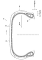
- FIG. 1 is a cross-sectional view of the pneumatic tire 10 along the tire width direction and the tire radial direction.
- FIG. 2 is a partially enlarged cross-sectional view of the pneumatic tire 10 along the tire width direction and the tire radial direction.
- FIG. 3 is a cross-sectional view along a tire width direction and a tire radial direction of a pneumatic tire 10A according to a modification.
- FIG. 1 is a cross-sectional view along a tire width direction and a tire radial direction of a pneumatic tire 10 according to the present embodiment.
- the pneumatic tire 10 includes a tread 20, a tire side portion 30, a carcass layer 40, and a bead portion 60.
- the pneumatic tire 10 has a symmetric shape with respect to the tire equator line CL.
- the pneumatic tire 10 is a tire for a cart, particularly a tire for a racing cart.
- the pneumatic tire 10 can be mounted on the front or rear wheel of a cart, although the tire size may vary.
- the tread 20 is a portion that comes into contact with the road surface.
- the tread 20 is formed of a tread rubber according to the characteristics of the pneumatic tire 10.
- the pneumatic tire 10 is assumed to be a slick tire in which a pattern is not formed on the surface (ground contact surface) of the tread 20, but the surface of the tread 20 has a predetermined tread pattern such as a circumferential groove. May be formed.
- the tire side portion 30 is continuous with the tread 20, and is located inside the tread 20 in the tire radial direction.
- the tire side portion 30 is a region from the outer end of the tread 20 in the tire width direction to the upper end of the bead portion 60.
- the tire side portion 30 is sometimes called a sidewall or the like.
- the tire side portion 30 is made of a plurality of types of rubber. The specific configuration of the tire side portion 30 will be described later.
- the carcass layer 40 forms the skeleton of the pneumatic tire 10.
- the carcass layer 40 is provided inside the tread 20 in the tire radial direction.
- the carcass layer 40 extends to the bead portion 60 via the tire side portion 30.
- the carcass layer 40 has a bias structure in which a plurality of carcass are stacked.
- the bead portion 60 is continuous with the tire side portion 30 and is located inside the tire side portion 30 in the tire radial direction.
- the bead portion 60 has an annular shape, and the carcass layer 40 is folded back from the inside in the tire width direction to the outside in the tire width direction via the bead portion 60.
- the pneumatic tire 10 has a higher case rigidity than a conventional racing cart tire.
- the case rigidity is the rigidity of the entire pneumatic tire 10, and particularly means a property of resisting deformation in the tire radial direction.
- the term “longitudinal rigidity” is used.
- the method for increasing the case rigidity is not particularly limited.
- a method of increasing the rigidity of the carcass layer 40 or the bead portion 60 may be used. More specifically, the diameter of the carcass cord is increased, the number of driving cords is increased, or the twist is reduced.
- the tire side portion 30 achieves both the case rigidity and the damping property by a plurality of rubber layers.
- FIG. 2 is a partially enlarged cross-sectional view of the pneumatic tire 10 along the tire width direction and the tire radial direction.
- the tread rubber 25 constituting the tread 20 is provided up to the shoulder end of the pneumatic tire 10 in the tire width direction. Specifically, the tread rubber 25 extends to the outside of the tire side portion 30 in the tire radial direction.
- the tire side portion 30 is composed of a plurality of rubber layers. Specifically, the tire side portion 30 includes an inner rubber layer 31 and an outer rubber layer 36.
- the inner rubber layer 31 is provided outside the carcass layer 40 in the tire width direction.
- the outer rubber layer 36 is provided outside the inner rubber layer 31 in the tire width direction.
- the carcass layer 40 is composed of two carcass, a first carcass 41 and a second carcass 46.
- the first carcass 41 is provided on the inner side in the tire radial direction and on the inner side in the width direction.
- the second carcass 46 is provided outside the first carcass 41 in the tire radial direction and outside in the tire width direction.
- the carcass layer 40 has a folded portion 40f that is folded outward in the tire width direction via the bead portion 60. Specifically, the folded portion 40f is folded from the inside in the tire width direction to the outside in the tire width direction via the bead core 61. The folded portion 40f extends to the outside of the bead filler 62 in the tire width direction.
- the bead filler 62 is a member that fills the space in the tire radial direction outside of the bead core 61 formed by folding the folded portion 40f, and is also called a stiffener.
- the inner rubber layer 31 is provided outside the folded portion 40f of the carcass layer 40 in the tire width direction.
- the inner rubber layer 31 and the outer rubber layer 36 are preferably provided at least in the range of 20% to 80% of the section height SH of the pneumatic tire 10.
- the section height SH is the height of the pneumatic tire 10 from the radially inner end of the bead portion 60 to the radially outer end of the tread 20.
- Tantan ⁇ out which is the loss tangent tan ⁇ of the outer rubber layer 36, is larger than tan ⁇ in, which is the loss tangent tan ⁇ of the inner rubber layer 31. Specifically, tan ⁇ out at 30 ° C is larger than tan ⁇ in at 30 ° C.
- the loss tangent tan ⁇ (the ratio of the dynamic loss elastic modulus (E ") to the dynamic storage elastic modulus (E ') (E" / E')) refers to vulcanized rubber with a thickness of 2 mm, a width of 5 mm, and a length of 5 mm. A test specimen with a length of 20 mm is given an initial load of 160 g, an initial strain of 1%, and a frequency of 50 Hz.
- the dynamic storage elastic modulus (E ') is a temperature of 30 ° C unless otherwise specified. Means the value measured in.
- Tan ⁇ out is preferably 40% or more larger than tan ⁇ in. More specifically, tan ⁇ out / tan ⁇ in, which is the ratio between tan ⁇ out and tan ⁇ in, is preferably 1.4 or more and 4.0 or less. In the present embodiment, tan ⁇ out is about 0.3 to 0.43, and tan ⁇ in is about 0.1 to 0.2.
- the thickness T2 of the outer rubber layer 36 along the tire width direction is along the tire width direction of the inner rubber layer 31. Thicker than T1.
- the thickness T2 is about 1.5 mm to 3.0 mm and the thickness T1 is about 0.5 mm to 1.0 mm.
- Table 1 shows the comparison test results of the lap time in the cart course.
- the conventional example shown in Table 1 is a conventional racing cart tire in which the tire side portion 30 is formed of one layer of rubber.
- the embodiment shown in Table 1 is the same as the pneumatic tire 10 described above, and includes an inner rubber layer 31 and an outer rubber layer 36.
- Test course and test distance domestic cart course (30 laps of about 1 km per lap)
- Test vehicle Pipe frame cart, two-stroke engine-Tire size: 5 inches
- Table 2 shows the results of comparison of tire longitudinal rigidity and damping.
- Longitudinal rigidity means rigidity in the tire radial direction when a load is applied to the tire, and is equivalent to case rigidity in the present embodiment.
- the longitudinal rigidity is a feeling evaluation by a test driver based on the conventional example.
- “Attenuation” means the degree to which the tire bends as the driver intends when a load is applied to the tire during cornering. If the damping property is high, the tire can be kept neatly bent, so that it is easy to make a vehicle posture at the time of cornering in which an appropriate load is applied to the tire outside the corner.
- the damping property is also a feeling evaluation by a test driver based on the conventional example.
- the tire side portion 30 has the inner rubber layer 31 and the outer rubber layer 36, and the loss tangent tan ⁇ out of the outer rubber layer 36 is tan ⁇ out, which is the loss tangent of the inner rubber layer 31. It is larger than tan ⁇ in which is tan ⁇ .
- the vehicle maintains the vehicle posture in which the vehicle is appropriately loaded on the outside of the corner during cornering of the vehicle (cart) equipped with the pneumatic tire 10. Easier to do.
- the pneumatic tire 10 can be maintained in a neatly bent state, it is easy to create a vehicle posture at the time of cornering in which a moderate load is applied to the tire outside the corner.
- Maintaining such a vehicle attitude is particularly useful for carts that do not have a suspension function.
- resilience from a vehicle posture appropriately loaded on the outside of the corner can be secured.
- the pneumatic tire 10 it is possible to exhibit appropriate damping properties due to bending of the tire while increasing case rigidity. Thereby, it is possible to achieve both improvement in durability of the pneumatic tire 10 and improvement in steering stability. Furthermore, lap time and the like can be improved by improving the grip force on the road surface by improving the case rigidity and improving the steering stability.
- the thickness T2 of the outer rubber layer 36 along the tire width direction is larger than the thickness T1 of the inner rubber layer 31 along the tire width direction. For this reason, the width of the tuning of the outer rubber layer 36 to the desired damping property is widened. Further, the outer rubber layer 36 is worn by the vehicle (cart) due to contact with other vehicles or tires while the vehicle is running, but can maintain the minimum damping even in such a case.
- tan ⁇ out / tan ⁇ in is 1.4 or more and 4.0 or less. For this reason, both case rigidity (longitudinal rigidity) and damping property can be achieved at a high level. If tan ⁇ out / tan ⁇ in is less than 1.4, the case rigidity tends to increase, but it is difficult to maintain proper damping. On the other hand, if tan ⁇ out / tan ⁇ in exceeds 4.0, the damping property becomes excessive and the response (return) is delayed, so that the turning performance decreases.
- the inner rubber layer 31 is provided outside the folded portion 40f of the carcass layer 40 in the tire width direction. Since the inner rubber layer 31 is provided outside the folded portion 40f of the carcass layer 40 in the tire width direction as described above, the inner rubber layer 31 greatly affects the securing (adjustment) of the case rigidity of the pneumatic tire 10. For this reason, the width of the tuning of the inner rubber layer 31 to a desired case rigidity is widened.
- the pneumatic tire 10 is a tire for a racing cart, but may be a tire for a general automobile (including a racing vehicle).
- FIG. 3 is a cross-sectional view of a pneumatic tire 10A according to a modification along the tire width direction and the tire radial direction.
- parts different from the pneumatic tire 10 will be mainly described.
- the pneumatic tire 10A is a general automobile tire, and includes a belt layer 50 as compared with the pneumatic tire 10.
- the belt layer 50 includes a pair of interleaved belt layers, and a reinforcing belt layer (also referred to as a spiral belt) including a cord (not shown) provided along the tire circumferential direction on the tire radial outer side of the interleaved belt layers.
- a reinforcing belt layer also referred to as a spiral belt
- a cord not shown
- the pneumatic tire 10A includes such a belt layer 50, and the carcass layer 40A has a radial structure.
- the tread rubber 25A that constitutes the tread 20 extends to the outside of the tire side portion 30 in the tire radial direction.
- the tire side portion 30 is composed of an inner rubber layer 31A and an outer rubber layer 36A.
- the configurations of the inner rubber layer 31A and the outer rubber layer 36A are substantially the same as the inner rubber layer 31 and the outer rubber layer 36A of the pneumatic tire 10 described above.
- the thicknesses (T1, ⁇ T2) of the inner rubber layer 31A and the outer rubber layer 36A are set to appropriate values according to the size and use of the pneumatic tire 10A. Also, the absolute value of the loss tangent tan ⁇ is set to an appropriate value according to the size and use of the pneumatic tire 10A.
- the thickness T2 of the outer rubber layer 36 along the tire width direction is larger than the thickness T1 of the inner rubber layer 31 along the tire width direction. It does not necessarily have to be thicker than the inner rubber layer 31. That is, it is only necessary that tan ⁇ out is larger than tan ⁇ in.
- the inner rubber layer 31 is provided on the outer side in the tire width direction of the folded portion 40f of the carcass layer 40, but depending on the tire size or type, the inner rubber layer 31 is It may be provided inside the direction.
- the tire side having the inner rubber layer 31 and the outer rubber layer 36 on both sides with reference to the tire equator line CL specifically, on the in side (inside of the vehicle) and the out side (outside of the vehicle).
- the portion 30 is provided, the tire side portion 30 having the inner rubber layer 31 and the outer rubber layer 36 may be provided only on one side with respect to the tire equator line CL.
- the tire side portion 30 having the inner rubber layer 31 and the outer rubber layer 36 is assembled to the rim wheel so as to be located on the out side.
Landscapes
- Engineering & Computer Science (AREA)
- Mechanical Engineering (AREA)
- Tires In General (AREA)
Abstract
空気入りタイヤ(10)のタイヤサイド部(30)は、カーカス層(40)のタイヤ幅方向外側に設けられる内側ゴム層(31)と、内側ゴム層(31)のタイヤ幅方向外側に設けられる外側ゴム層(36)とを有する。外側ゴム層(36)の損失正接tanδであるtanδoutは、内側ゴム層(31)の損失正接tanδであるtanδinよりも大きい。
Description
本発明は、タイヤが撓むことによって適切な減衰性を発揮し得るタイヤ、特に、レーシングカート用として好適なタイヤに関する。
従来、レーシングカート用バイアスタイヤにおいて、耐久性と操縦安定性とを両立するべく、トレッドの裏側に有機繊維のコードによって構成された補強層を設ける構造が知られている(特許文献1参照)。
具体的には、バイアス構造のカーカス層の間に、一方のトレッドショルダーから他方のトレッドショルダーに亘ってシート状の補強層が設けられている。
ところで、上述したようなレーシングカート用バイアスタイヤでも、耐久性向上の観点からは、タイヤのケース剛性を高めることが好ましい。
しかしながら、サスペンション機能を有していないレーシングカートなどの車両に装着されるタイヤの場合、タイヤが、サスペンション機能、具体的には、ダンパーの機能を担うため、タイヤのケース剛性を高くし過ぎると、タイヤが撓むことによる適切な減衰性を発揮できなくなる。
タイヤが撓むことによる適切な減衰性を発揮できないと、車両のコーナリング中に、車両がコーナー外側に適度に荷重された車両姿勢を維持することが難しくなる。このため、車両の操縦安定性が低下する。
そこで、本発明は、このような状況に鑑みてなされたものであり、ケース剛性を高めつつ、タイヤが撓むことによる適切な減衰性を発揮し得るタイヤの提供を目的とする。
本発明の一態様は、路面に接するトレッド(トレッド20)と、前記トレッドに連なり、前記トレッドのタイヤ径方向内側に位置するタイヤサイド部(タイヤサイド部30)と、前記タイヤサイド部に連なり、前記タイヤサイド部のタイヤ径方向内側に位置するビード部(ビード部)と、前記トレッドのタイヤ径方向内側に設けられ、前記ビード部まで延びるカーカス層(カーカス層40)とを含むタイヤ(例えば、空気入りタイヤ10)であって、前記タイヤサイド部は、前記カーカス層のタイヤ幅方向外側に設けられる内側ゴム層(内側ゴム層31)と、前記内側ゴム層のタイヤ幅方向外側に設けられる外側ゴム層(外側ゴム層36)とを有し、前記外側ゴム層の損失正接tanδであるtanδoutは、前記内側ゴム層の損失正接tanδであるtanδinよりも大きい。
以下、実施形態を図面に基づいて説明する。なお、同一の機能や構成には、同一または類似の符号を付して、その説明を適宜省略する。
(1)タイヤの全体概略構成
図1は、本実施形態に係る空気入りタイヤ10のタイヤ幅方向及びタイヤ径方向に沿った断面図である。
図1は、本実施形態に係る空気入りタイヤ10のタイヤ幅方向及びタイヤ径方向に沿った断面図である。
図1に示すように、空気入りタイヤ10は、トレッド20、タイヤサイド部30、カーカス層40及びビード部60を備える。空気入りタイヤ10は、タイヤ赤道線CLを基準として、対称の形状を有する。
本実施形態では、空気入りタイヤ10は、カート用のタイヤであり、特に、レーシングカート用のタイヤである。空気入りタイヤ10は、タイヤサイズは異なり得るものの、カートの前輪または後輪に装着できる。
トレッド20は、路面と接する部分である。トレッド20は、空気入りタイヤ10の特性に応じたトレッドゴムによって形成される。なお、本実施形態では、空気入りタイヤ10は、トレッド20の表面(接地面)にパターンが形成されないスリックタイヤを前提としているが、トレッド20の表面には、周方向溝など、所定のトレッドパターンが形成されてもよい。
タイヤサイド部30は、トレッド20に連なり、トレッド20のタイヤ径方向内側に位置する。タイヤサイド部30は、トレッド20のタイヤ幅方向外側端からビード部60の上端までの領域である。タイヤサイド部30は、サイドウォールなどと呼ばれることもある。
本実施形態では、タイヤサイド部30は、複数種類のゴムによって構成される。タイヤサイド部30の具体的な構成について後述する。
カーカス層40は、空気入りタイヤ10の骨格を形成する。カーカス層40は、トレッド20のタイヤ径方向内側に設けられる。また、カーカス層40は、タイヤサイド部30を介してビード部60まで延びる。
本実施形態では、カーカス層40は、複数のカーカスが重ねられたバイアス構造である。
ビード部60は、タイヤサイド部30に連なり、タイヤサイド部30のタイヤ径方向内側に位置する。ビード部60は、円環状であり、ビード部60を介してカーカス層40がタイヤ幅方向内側からタイヤ幅方向外側に折り返されている。
なお、空気入りタイヤ10では、従来のレーシングカート用のタイヤよりもケース剛性が高められている。ケース剛性とは、空気入りタイヤ10全体としての剛性であり、特に、タイヤ径方向における変形に抵抗する性質を意味する。本実施形態では、後述するように、「縦剛性」の意味で用いる。
ケース剛性を高める方法については、特に限定されない。カーカス層40或いはビード部60の剛性を高める方法が挙げられる。具体的には、カーカスコードの径を太くする、打ち込み本数を増やす、或いは撚りを減らすことなどが挙げられる。
タイヤサイド部30は、後述するように、複数のゴム層によって、ケース剛性と減衰性との両立を図る。
(2)タイヤサイド部及びビード部の構造
次に、図2を参照して、タイヤサイド部30及びビード部60の構造について説明する。図2は、空気入りタイヤ10のタイヤ幅方向及びタイヤ径方向に沿った一部拡大断面図である。
次に、図2を参照して、タイヤサイド部30及びビード部60の構造について説明する。図2は、空気入りタイヤ10のタイヤ幅方向及びタイヤ径方向に沿った一部拡大断面図である。
図2に示すように、トレッド20を構成するトレッドゴム25は、空気入りタイヤ10のタイヤ幅方向におけるショルダー端まで設けられている。具体的には、トレッドゴム25は、タイヤサイド部30のタイヤ径方向外側まで延在している。
タイヤサイド部30は、複数のゴム層によって構成される。具体的には、タイヤサイド部30は、内側ゴム層31と外側ゴム層36とによって構成される。
内側ゴム層31は、カーカス層40のタイヤ幅方向外側に設けられる。外側ゴム層36は、内側ゴム層31のタイヤ幅方向外側に設けられる。
カーカス層40は、第1カーカス41及び第2カーカス46の2枚のカーカスによって構成される。第1カーカス41は、タイヤ径方向内側及び体は幅方向内側に設けられる。第2カーカス46は、第1カーカス41のタイヤ径方向外側及びタイヤ幅方向外側に設けられる。
また、カーカス層40は、ビード部60を介してタイヤ幅方向外側に折り返された折り返し部40fを有する。具体的には、折り返し部40fは、ビードコア61を介してタイヤ幅方向内側からタイヤ幅方向外側に折り返される。折り返し部40fは、ビードフィラー62のタイヤ幅方向外側まで延びる。
ビードフィラー62は、折り返し部40fが折り返されることによって形成されたビードコア61のタイヤ径方向外側の空間を埋める部材であり、スティフナーとも呼ばれる。
内側ゴム層31は、カーカス層40の折り返し部40fのタイヤ幅方向外側に設けられる。
内側ゴム層31及び外側ゴム層36は、空気入りタイヤ10のセクションハイトSHの20%~80%の範囲に少なくとも設けられることが好ましい。セクションハイトSHは、ビード部60のタイヤ径方向内側端からトレッド20のタイヤ径方向外側端までの空気入りタイヤ10の高さである。
外側ゴム層36の損失正接tanδであるtanδoutは、内側ゴム層31の損失正接tanδであるtanδinよりも大きい。具体的には、30℃におけるtanδoutは、30℃におけるtanδinよりも大きい。
損失正接tanδ(動的損失弾性率(E”)と動的貯蔵弾性率(E’)との比(E”/E’))とは、加硫ゴムに関し、厚さ2mm、幅5mm、長さ20mmの試験片に初期荷重160gを与え、初期歪み1%、振動数50Hzの条件で測定した値をいい、動的貯蔵弾性率(E’)は、別段の記載がない限り、温度30℃で測定した値を意味する。
tanδoutは、tanδinを基準として40%以上大きいことが好ましい。より具体的には、tanδoutとtanδinとの比であるtanδout/tanδinは、1.4以上、4.0以下であることが好ましい。本実施形態では、tanδoutは、0.3~0.43、tanδinは、0.1~0.2程度である。
また、本実施形態では、空気入りタイヤ10の最大幅部分Wmax(図1参照)において、外側ゴム層36のタイヤ幅方向に沿った厚さT2は、内側ゴム層31のタイヤ幅方向に沿った厚さT1よりも厚い。
具体的には、レーシングカート用の空気入りタイヤ10(5インチ)の場合、厚さT2は、1.5mm~3.0mm、厚さT1は、0.5mm~1.0mm程度とすることが好ましい。
(3)作用・効果
次に、上述した空気入りタイヤ10の作用及び効果について説明する。表1は、カートコースにおけるラップタイムの比較試験結果を示す。
次に、上述した空気入りタイヤ10の作用及び効果について説明する。表1は、カートコースにおけるラップタイムの比較試験結果を示す。
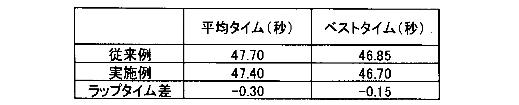
表1に示す従来例は、タイヤサイド部30が1層のゴムで形成されている従来のレーシングカート用タイヤである。表1に示す実施例は、上述した空気入りタイヤ10と同様であり、内側ゴム層31及び外側ゴム層36を備える。
当該比較試験の条件などは、以下のとおりである。
・試験コース及び試験距離: 国内カート用コース(1周約1kmを30周走行)
・試験車両: パイプフレーム製カート,2ストロークエンジン
・タイヤサイズ: 5インチ
表2は、タイヤの縦剛性と減衰性の比較結果を示す。
・試験車両: パイプフレーム製カート,2ストロークエンジン
・タイヤサイズ: 5インチ
表2は、タイヤの縦剛性と減衰性の比較結果を示す。

「縦剛性」とは、タイヤに荷重が負荷された状態におけるタイヤ径方向の剛性を意味し、本実施形態では、ケース剛性と等価である。縦剛性は、従来例を基準としたテストドライバーによるフィーリング評価である。
「減衰性」とは、コーナリング時にタイヤに荷重が負荷されることによって、タイヤがドライバーの意思どおりに撓んでくれる程度を意味する。減衰性が高ければ、タイヤが綺麗に撓んだ状態を維持できるため、コーナー外側のタイヤに適度に荷重が負荷されたコーナリング時の車両姿勢を作り易い。減衰性も、従来例を基準としたテストドライバーによるフィーリング評価である。
上述したように、空気入りタイヤ10では、タイヤサイド部30が内側ゴム層31と外側ゴム層36とを有し、外側ゴム層36の損失正接tanδであるtanδoutは、内側ゴム層31の損失正接tanδであるtanδinよりも大きい。
このため、特に、外側ゴム層36が減衰性の確保に貢献するため、空気入りタイヤ10が装着された車両(カート)のコーナリング中に、車両がコーナー外側に適度に荷重された車両姿勢を維持し易くなる。
つまり、空気入りタイヤ10が綺麗に撓んだ状態を維持できるため、コーナー外側のタイヤに適度に荷重が負荷されたコーナリング時の車両姿勢を作り易い。
このような車両姿勢の維持は、サスペンション機能を有していないカートでは、特に有用である。また、極端に大きな減衰性は与えないようにすることによって、コーナー外側に適度に荷重された車両姿勢からの復元性も確保し得る。
なお、このように、特に外側ゴム層36によって減衰性を確保できるため、空気入りタイヤ10のケース剛性については高めても問題ない。
すなわち、空気入りタイヤ10によれば、ケース剛性を高めつつ、タイヤが撓むことによる適切な減衰性を発揮し得る。これにより、空気入りタイヤ10の耐久性向上と、操縦安定性の向上とを両立し得る。さらに、ケース剛性の向上による路面のグリップ力の向上、及び操縦安定性が向上することによって、ラップタイムなどを向上し得る。
本実施形態では、外側ゴム層36のタイヤ幅方向に沿った厚さT2は、内側ゴム層31のタイヤ幅方向に沿った厚さT1よりも厚い。このため、外側ゴム層36のチューニングによる所望の減衰性への対応幅が広がる。また、外側ゴム層36は、車両(カート)が走行中に、他の車両やタイヤと接触によってすり減るが、このような場合でも最低限の減衰性を維持し得る。
本実施形態では、tanδout/tanδinは、1.4以上、4.0以下である。このため、ケース剛性(縦剛性)と、減衰性とを高い次元で両立し得る。tanδout/tanδinが1.4未満だと、ケース剛性は高くなる方向だが、適切な減衰性を維持することが難しい。また、tanδout/tanδinが4.0を超えると、減衰性が過剰になり、応答(戻り)が遅れるため、旋回性能が低下する。
本実施形態では、内側ゴム層31は、カーカス層40の折り返し部40fのタイヤ幅方向外側に設けられる。このように内側ゴム層31がカーカス層40の折り返し部40fのタイヤ幅方向外側に設けられることによって、内側ゴム層31は、空気入りタイヤ10のケース剛性の確保(調整)に大きく影響する。このため、内側ゴム層31のチューニングによる所望のケース剛性への対応幅が広がる。
(4)その他の実施形態
以上、実施例に沿って本発明の内容を説明したが、本発明はこれらの記載に限定されるものではなく、種々の変形及び改良が可能であることは、当業者には自明である。
以上、実施例に沿って本発明の内容を説明したが、本発明はこれらの記載に限定されるものではなく、種々の変形及び改良が可能であることは、当業者には自明である。
例えば、上述した実施形態では、空気入りタイヤ10は、レーシングカート用のタイヤであったが、一般的な自動車(レース用の車両を含む)用のタイヤであってもよい。
図3は、変更例に係る空気入りタイヤ10Aのタイヤ幅方向及びタイヤ径方向に沿った断面図である。以下、空気入りタイヤ10と異なる部分について主に説明する。
図3に示すように、空気入りタイヤ10Aは、一般的な自動車用のタイヤであり、空気入りタイヤ10と比較すると、ベルト層50を備える。
ベルト層50は、一対の交錯ベルト層と、当該交錯ベルト層のタイヤ径方向外側において、タイヤ周方向に沿って設けられたコード(不図示)を含む補強ベルト層(スパイラルベルトとも呼ばれる)とを有する。
空気入りタイヤ10Aは、このようなベルト層50を備えており、カーカス層40Aは、ラジアル構造である。
トレッド20を構成するトレッドゴム25Aは、タイヤサイド部30のタイヤ径方向外側まで延在している。
タイヤサイド部30は、内側ゴム層31Aと外側ゴム層36Aとによって構成される。内側ゴム層31A及び外側ゴム層36Aの構成は、上述した空気入りタイヤ10の内側ゴム層31及び外側ゴム層36Aと概ね同様である。
なお、内側ゴム層31A及び外側ゴム層36Aの厚さ(T1, T2)は、空気入りタイヤ10Aのサイズ及び用途に合わせて適切な値に設定される。また、損失正接tanδの絶対値についても、空気入りタイヤ10Aのサイズ及び用途に合わせて適切な値に設定される。
また、上述した実施形態では、外側ゴム層36のタイヤ幅方向に沿った厚さT2は、内側ゴム層31のタイヤ幅方向に沿った厚さT1よりも厚かったが、外側ゴム層36は、必ずしも内側ゴム層31よりも厚くなくても構わない。つまり、tanδoutがtanδinよりも大きければよい。
上述した実施形態では、内側ゴム層31は、カーカス層40の折り返し部40fのタイヤ幅方向外側に設けられていたが、タイヤサイズまたは種別によっては、内側ゴム層31は、カーカス層40のタイヤ幅方向内側に設けられてもよい。
上述した実施形態では、タイヤ赤道線CLを基準とした両側、具体的にはイン側(車両装着内側)及びアウト側(車両装着外側)に、内側ゴム層31及び外側ゴム層36を有するタイヤサイド部30が備えられていたが、タイヤ赤道線CLを基準とした一方側のみに、内側ゴム層31及び外側ゴム層36を有するタイヤサイド部30が備えられていてもよい。この場合、内側ゴム層31及び外側ゴム層36を有するタイヤサイド部30は、アウト側に位置するように、リムホイールに組み付けられる。
上記のように、本発明の実施形態を記載したが、この開示の一部をなす論述及び図面はこの発明を限定するものであると理解すべきではない。この開示から当業者には様々な代替実施の形態、実施例及び運用技術が明らかとなろう。
10, 10A 空気入りタイヤ
20 トレッド
25, 25A トレッドゴム
30 タイヤサイド部
31, 31A 内側ゴム層
36, 36A 外側ゴム層
40 カーカス層
40f 折り返し部
41 第1カーカス
46 第2カーカス
50 ベルト層
60 ビード部
61 ビードコア
62 ビードフィラー
20 トレッド
25, 25A トレッドゴム
30 タイヤサイド部
31, 31A 内側ゴム層
36, 36A 外側ゴム層
40 カーカス層
40f 折り返し部
41 第1カーカス
46 第2カーカス
50 ベルト層
60 ビード部
61 ビードコア
62 ビードフィラー
Claims (4)
- 路面に接するトレッドと、
前記トレッドに連なり、前記トレッドのタイヤ径方向内側に位置するタイヤサイド部と、
前記タイヤサイド部に連なり、前記タイヤサイド部のタイヤ径方向内側に位置するビード部と、
前記トレッドのタイヤ径方向内側に設けられ、前記ビード部まで延びるカーカス層と
を含むタイヤであって、
前記タイヤサイド部は、
前記カーカス層のタイヤ幅方向外側に設けられる内側ゴム層と、
前記内側ゴム層のタイヤ幅方向外側に設けられる外側ゴム層と
を有し、
前記外側ゴム層の損失正接tanδであるtanδoutは、前記内側ゴム層の損失正接tanδであるtanδinよりも大きいタイヤ。 - 前記外側ゴム層のタイヤ幅方向に沿った厚さは、前記内側ゴム層のタイヤ幅方向に沿った厚さよりも厚い請求項1に記載のタイヤ。
- 前記tanδoutと前記tanδinとの比であるtanδout/tanδinは、1.4以上、4.0以下である請求項1または2に記載のタイヤ。
- 前記カーカス層は、前記ビード部を介してタイヤ幅方向外側に折り返された折り返し部を有し、
前記内側ゴム層は、前記折り返し部のタイヤ幅方向外側に設けられる請求項1乃至3の何れか一項に記載のタイヤ。
Applications Claiming Priority (2)
| Application Number | Priority Date | Filing Date | Title |
|---|---|---|---|
| JP2018151375A JP2020026194A (ja) | 2018-08-10 | 2018-08-10 | タイヤ |
| JP2018-151375 | 2018-08-10 |
Publications (1)
| Publication Number | Publication Date |
|---|---|
| WO2020032001A1 true WO2020032001A1 (ja) | 2020-02-13 |
Family
ID=69414722
Family Applications (1)
| Application Number | Title | Priority Date | Filing Date |
|---|---|---|---|
| PCT/JP2019/030838 Ceased WO2020032001A1 (ja) | 2018-08-10 | 2019-08-06 | タイヤ |
Country Status (2)
| Country | Link |
|---|---|
| JP (1) | JP2020026194A (ja) |
| WO (1) | WO2020032001A1 (ja) |
Cited By (1)
| Publication number | Priority date | Publication date | Assignee | Title |
|---|---|---|---|---|
| CN115087551A (zh) * | 2020-02-17 | 2022-09-20 | 横滨橡胶株式会社 | 充气轮胎 |
Citations (5)
| Publication number | Priority date | Publication date | Assignee | Title |
|---|---|---|---|---|
| JP2004291911A (ja) * | 2003-03-28 | 2004-10-21 | Bridgestone Corp | 空気入りタイヤ |
| JP2008254619A (ja) * | 2007-04-06 | 2008-10-23 | Sumitomo Rubber Ind Ltd | 空気入りタイヤ |
| JP2011079357A (ja) * | 2009-10-02 | 2011-04-21 | Yokohama Rubber Co Ltd:The | 空気入りタイヤ |
| JP2013224111A (ja) * | 2012-04-23 | 2013-10-31 | Sumitomo Rubber Ind Ltd | 空気入りタイヤ |
| JP2017136912A (ja) * | 2016-02-02 | 2017-08-10 | 住友ゴム工業株式会社 | 空気入りタイヤ |
-
2018
- 2018-08-10 JP JP2018151375A patent/JP2020026194A/ja active Pending
-
2019
- 2019-08-06 WO PCT/JP2019/030838 patent/WO2020032001A1/ja not_active Ceased
Patent Citations (5)
| Publication number | Priority date | Publication date | Assignee | Title |
|---|---|---|---|---|
| JP2004291911A (ja) * | 2003-03-28 | 2004-10-21 | Bridgestone Corp | 空気入りタイヤ |
| JP2008254619A (ja) * | 2007-04-06 | 2008-10-23 | Sumitomo Rubber Ind Ltd | 空気入りタイヤ |
| JP2011079357A (ja) * | 2009-10-02 | 2011-04-21 | Yokohama Rubber Co Ltd:The | 空気入りタイヤ |
| JP2013224111A (ja) * | 2012-04-23 | 2013-10-31 | Sumitomo Rubber Ind Ltd | 空気入りタイヤ |
| JP2017136912A (ja) * | 2016-02-02 | 2017-08-10 | 住友ゴム工業株式会社 | 空気入りタイヤ |
Cited By (2)
| Publication number | Priority date | Publication date | Assignee | Title |
|---|---|---|---|---|
| CN115087551A (zh) * | 2020-02-17 | 2022-09-20 | 横滨橡胶株式会社 | 充气轮胎 |
| CN115087551B (zh) * | 2020-02-17 | 2023-11-03 | 横滨橡胶株式会社 | 充气轮胎 |
Also Published As
| Publication number | Publication date |
|---|---|
| JP2020026194A (ja) | 2020-02-20 |
Similar Documents
| Publication | Publication Date | Title |
|---|---|---|
| JP4567482B2 (ja) | 空気入りタイヤ | |
| JP2814101B2 (ja) | 空気入りラジアルタイヤ | |
| RU2421343C1 (ru) | Шина для мотоцикла и способ ее получения | |
| US20100314019A1 (en) | Pneumatic tire for motocross | |
| RU2424122C1 (ru) | Пара шин для двухколесного мотоцикла | |
| CN103373176B (zh) | 充气轮胎 | |
| JP4383466B2 (ja) | 自動二輪車用空気入りタイヤ | |
| JP2020175860A (ja) | 自動二輪車用タイヤ及び自動二輪車用タイヤセット | |
| JPH06297913A (ja) | ラジアルタイヤ | |
| JP2009227229A (ja) | 空気入りラジアルタイヤ | |
| JP3650170B2 (ja) | 二輪車用空気入りタイヤ | |
| JP2001191764A (ja) | 空気入りタイヤ | |
| JP2002205513A (ja) | 空気入りラジアルタイヤ | |
| WO2020032001A1 (ja) | タイヤ | |
| JP5103081B2 (ja) | 自動二輪車用空気入りタイヤ | |
| JP7230479B2 (ja) | 二輪自動車用タイヤ | |
| JP2022083810A (ja) | 自動二輪車用タイヤ | |
| JP2966749B2 (ja) | 自動二輪車 | |
| JP2000190714A (ja) | 空気入りタイヤ | |
| JP5240981B2 (ja) | 二輪車用空気入りタイヤ | |
| JP6645179B2 (ja) | 空気入りタイヤ | |
| JP3353933B2 (ja) | レーシングカート用空気入りバイアスタイヤ | |
| JP4978087B2 (ja) | 空気入りタイヤ | |
| JP5173649B2 (ja) | 空気入りタイヤ及びその装着方法 | |
| JP2002347410A (ja) | 自動二輪車用タイヤ |
Legal Events
| Date | Code | Title | Description |
|---|---|---|---|
| 121 | Ep: the epo has been informed by wipo that ep was designated in this application |
Ref document number: 19847757 Country of ref document: EP Kind code of ref document: A1 |
|
| NENP | Non-entry into the national phase |
Ref country code: DE |
|
| 122 | Ep: pct application non-entry in european phase |
Ref document number: 19847757 Country of ref document: EP Kind code of ref document: A1 |