WO2020031973A1 - 流体漏れ検出システム - Google Patents
流体漏れ検出システム Download PDFInfo
- Publication number
- WO2020031973A1 WO2020031973A1 PCT/JP2019/030765 JP2019030765W WO2020031973A1 WO 2020031973 A1 WO2020031973 A1 WO 2020031973A1 JP 2019030765 W JP2019030765 W JP 2019030765W WO 2020031973 A1 WO2020031973 A1 WO 2020031973A1
- Authority
- WO
- WIPO (PCT)
- Prior art keywords
- unit
- battery
- measurement
- data
- fluid
- Prior art date
- Legal status (The legal status is an assumption and is not a legal conclusion. Google has not performed a legal analysis and makes no representation as to the accuracy of the status listed.)
- Ceased
Links
Images




Classifications
-
- G—PHYSICS
- G01—MEASURING; TESTING
- G01M—TESTING STATIC OR DYNAMIC BALANCE OF MACHINES OR STRUCTURES; TESTING OF STRUCTURES OR APPARATUS, NOT OTHERWISE PROVIDED FOR
- G01M3/00—Investigating fluid-tightness of structures
- G01M3/002—Investigating fluid-tightness of structures by using thermal means
-
- F—MECHANICAL ENGINEERING; LIGHTING; HEATING; WEAPONS; BLASTING
- F15—FLUID-PRESSURE ACTUATORS; HYDRAULICS OR PNEUMATICS IN GENERAL
- F15B—SYSTEMS ACTING BY MEANS OF FLUIDS IN GENERAL; FLUID-PRESSURE ACTUATORS, e.g. SERVOMOTORS; DETAILS OF FLUID-PRESSURE SYSTEMS, NOT OTHERWISE PROVIDED FOR
- F15B15/00—Fluid-actuated devices for displacing a member from one position to another; Gearing associated therewith
- F15B15/08—Characterised by the construction of the motor unit
- F15B15/14—Characterised by the construction of the motor unit of the straight-cylinder type
-
- F—MECHANICAL ENGINEERING; LIGHTING; HEATING; WEAPONS; BLASTING
- F15—FLUID-PRESSURE ACTUATORS; HYDRAULICS OR PNEUMATICS IN GENERAL
- F15B—SYSTEMS ACTING BY MEANS OF FLUIDS IN GENERAL; FLUID-PRESSURE ACTUATORS, e.g. SERVOMOTORS; DETAILS OF FLUID-PRESSURE SYSTEMS, NOT OTHERWISE PROVIDED FOR
- F15B15/00—Fluid-actuated devices for displacing a member from one position to another; Gearing associated therewith
- F15B15/08—Characterised by the construction of the motor unit
- F15B15/14—Characterised by the construction of the motor unit of the straight-cylinder type
- F15B15/1423—Component parts; Constructional details
- F15B15/1457—Piston rods
- F15B15/1461—Piston rod sealings
-
- F—MECHANICAL ENGINEERING; LIGHTING; HEATING; WEAPONS; BLASTING
- F15—FLUID-PRESSURE ACTUATORS; HYDRAULICS OR PNEUMATICS IN GENERAL
- F15B—SYSTEMS ACTING BY MEANS OF FLUIDS IN GENERAL; FLUID-PRESSURE ACTUATORS, e.g. SERVOMOTORS; DETAILS OF FLUID-PRESSURE SYSTEMS, NOT OTHERWISE PROVIDED FOR
- F15B15/00—Fluid-actuated devices for displacing a member from one position to another; Gearing associated therewith
- F15B15/20—Other details, e.g. assembly with regulating devices
-
- F—MECHANICAL ENGINEERING; LIGHTING; HEATING; WEAPONS; BLASTING
- F15—FLUID-PRESSURE ACTUATORS; HYDRAULICS OR PNEUMATICS IN GENERAL
- F15B—SYSTEMS ACTING BY MEANS OF FLUIDS IN GENERAL; FLUID-PRESSURE ACTUATORS, e.g. SERVOMOTORS; DETAILS OF FLUID-PRESSURE SYSTEMS, NOT OTHERWISE PROVIDED FOR
- F15B19/00—Testing; Calibrating; Fault detection or monitoring; Simulation or modelling of fluid-pressure systems or apparatus not otherwise provided for
- F15B19/005—Fault detection or monitoring
-
- F—MECHANICAL ENGINEERING; LIGHTING; HEATING; WEAPONS; BLASTING
- F15—FLUID-PRESSURE ACTUATORS; HYDRAULICS OR PNEUMATICS IN GENERAL
- F15B—SYSTEMS ACTING BY MEANS OF FLUIDS IN GENERAL; FLUID-PRESSURE ACTUATORS, e.g. SERVOMOTORS; DETAILS OF FLUID-PRESSURE SYSTEMS, NOT OTHERWISE PROVIDED FOR
- F15B20/00—Safety arrangements for fluid actuator systems; Applications of safety devices in fluid actuator systems; Emergency measures for fluid actuator systems
- F15B20/005—Leakage; Spillage; Hose burst
-
- G—PHYSICS
- G01—MEASURING; TESTING
- G01M—TESTING STATIC OR DYNAMIC BALANCE OF MACHINES OR STRUCTURES; TESTING OF STRUCTURES OR APPARATUS, NOT OTHERWISE PROVIDED FOR
- G01M3/00—Investigating fluid-tightness of structures
- G01M3/02—Investigating fluid-tightness of structures by using fluid or vacuum
- G01M3/26—Investigating fluid-tightness of structures by using fluid or vacuum by measuring rate of loss or gain of fluid, e.g. by pressure-responsive devices, by flow detectors
-
- G—PHYSICS
- G01—MEASURING; TESTING
- G01M—TESTING STATIC OR DYNAMIC BALANCE OF MACHINES OR STRUCTURES; TESTING OF STRUCTURES OR APPARATUS, NOT OTHERWISE PROVIDED FOR
- G01M3/00—Investigating fluid-tightness of structures
- G01M3/02—Investigating fluid-tightness of structures by using fluid or vacuum
- G01M3/26—Investigating fluid-tightness of structures by using fluid or vacuum by measuring rate of loss or gain of fluid, e.g. by pressure-responsive devices, by flow detectors
- G01M3/32—Investigating fluid-tightness of structures by using fluid or vacuum by measuring rate of loss or gain of fluid, e.g. by pressure-responsive devices, by flow detectors for containers, e.g. radiators
- G01M3/3236—Investigating fluid-tightness of structures by using fluid or vacuum by measuring rate of loss or gain of fluid, e.g. by pressure-responsive devices, by flow detectors for containers, e.g. radiators by monitoring the interior space of the containers
- G01M3/3272—Investigating fluid-tightness of structures by using fluid or vacuum by measuring rate of loss or gain of fluid, e.g. by pressure-responsive devices, by flow detectors for containers, e.g. radiators by monitoring the interior space of the containers for verifying the internal pressure of closed containers
-
- G—PHYSICS
- G01—MEASURING; TESTING
- G01R—MEASURING ELECTRIC VARIABLES; MEASURING MAGNETIC VARIABLES
- G01R31/00—Arrangements for testing electric properties; Arrangements for locating electric faults; Arrangements for electrical testing characterised by what is being tested not provided for elsewhere
- G01R31/36—Arrangements for testing, measuring or monitoring the electrical condition of accumulators or electric batteries, e.g. capacity or state of charge [SoC]
- G01R31/382—Arrangements for monitoring battery or accumulator variables, e.g. SoC
- G01R31/3835—Arrangements for monitoring battery or accumulator variables, e.g. SoC involving only voltage measurements
-
- H—ELECTRICITY
- H01—ELECTRIC ELEMENTS
- H01M—PROCESSES OR MEANS, e.g. BATTERIES, FOR THE DIRECT CONVERSION OF CHEMICAL ENERGY INTO ELECTRICAL ENERGY
- H01M10/00—Secondary cells; Manufacture thereof
- H01M10/42—Methods or arrangements for servicing or maintenance of secondary cells or secondary half-cells
- H01M10/4228—Leak testing of cells or batteries
-
- H—ELECTRICITY
- H01—ELECTRIC ELEMENTS
- H01M—PROCESSES OR MEANS, e.g. BATTERIES, FOR THE DIRECT CONVERSION OF CHEMICAL ENERGY INTO ELECTRICAL ENERGY
- H01M10/00—Secondary cells; Manufacture thereof
- H01M10/42—Methods or arrangements for servicing or maintenance of secondary cells or secondary half-cells
- H01M10/48—Accumulators combined with arrangements for measuring, testing or indicating the condition of cells, e.g. the level or density of the electrolyte
-
- F—MECHANICAL ENGINEERING; LIGHTING; HEATING; WEAPONS; BLASTING
- F15—FLUID-PRESSURE ACTUATORS; HYDRAULICS OR PNEUMATICS IN GENERAL
- F15B—SYSTEMS ACTING BY MEANS OF FLUIDS IN GENERAL; FLUID-PRESSURE ACTUATORS, e.g. SERVOMOTORS; DETAILS OF FLUID-PRESSURE SYSTEMS, NOT OTHERWISE PROVIDED FOR
- F15B2211/00—Circuits for servomotor systems
- F15B2211/60—Circuit components or control therefor
- F15B2211/63—Electronic controllers
- F15B2211/6303—Electronic controllers using input signals
- F15B2211/6306—Electronic controllers using input signals representing a pressure
-
- F—MECHANICAL ENGINEERING; LIGHTING; HEATING; WEAPONS; BLASTING
- F15—FLUID-PRESSURE ACTUATORS; HYDRAULICS OR PNEUMATICS IN GENERAL
- F15B—SYSTEMS ACTING BY MEANS OF FLUIDS IN GENERAL; FLUID-PRESSURE ACTUATORS, e.g. SERVOMOTORS; DETAILS OF FLUID-PRESSURE SYSTEMS, NOT OTHERWISE PROVIDED FOR
- F15B2211/00—Circuits for servomotor systems
- F15B2211/60—Circuit components or control therefor
- F15B2211/63—Electronic controllers
- F15B2211/6303—Electronic controllers using input signals
- F15B2211/6343—Electronic controllers using input signals representing a temperature
-
- F—MECHANICAL ENGINEERING; LIGHTING; HEATING; WEAPONS; BLASTING
- F15—FLUID-PRESSURE ACTUATORS; HYDRAULICS OR PNEUMATICS IN GENERAL
- F15B—SYSTEMS ACTING BY MEANS OF FLUIDS IN GENERAL; FLUID-PRESSURE ACTUATORS, e.g. SERVOMOTORS; DETAILS OF FLUID-PRESSURE SYSTEMS, NOT OTHERWISE PROVIDED FOR
- F15B2211/00—Circuits for servomotor systems
- F15B2211/80—Other types of control related to particular problems or conditions
- F15B2211/857—Monitoring of fluid pressure systems
-
- F—MECHANICAL ENGINEERING; LIGHTING; HEATING; WEAPONS; BLASTING
- F15—FLUID-PRESSURE ACTUATORS; HYDRAULICS OR PNEUMATICS IN GENERAL
- F15B—SYSTEMS ACTING BY MEANS OF FLUIDS IN GENERAL; FLUID-PRESSURE ACTUATORS, e.g. SERVOMOTORS; DETAILS OF FLUID-PRESSURE SYSTEMS, NOT OTHERWISE PROVIDED FOR
- F15B2211/00—Circuits for servomotor systems
- F15B2211/80—Other types of control related to particular problems or conditions
- F15B2211/86—Control during or prevention of abnormal conditions
- F15B2211/862—Control during or prevention of abnormal conditions the abnormal condition being electric or electronic failure
-
- F—MECHANICAL ENGINEERING; LIGHTING; HEATING; WEAPONS; BLASTING
- F15—FLUID-PRESSURE ACTUATORS; HYDRAULICS OR PNEUMATICS IN GENERAL
- F15B—SYSTEMS ACTING BY MEANS OF FLUIDS IN GENERAL; FLUID-PRESSURE ACTUATORS, e.g. SERVOMOTORS; DETAILS OF FLUID-PRESSURE SYSTEMS, NOT OTHERWISE PROVIDED FOR
- F15B2211/00—Circuits for servomotor systems
- F15B2211/80—Other types of control related to particular problems or conditions
- F15B2211/86—Control during or prevention of abnormal conditions
- F15B2211/862—Control during or prevention of abnormal conditions the abnormal condition being electric or electronic failure
- F15B2211/8623—Electric supply failure
-
- F—MECHANICAL ENGINEERING; LIGHTING; HEATING; WEAPONS; BLASTING
- F15—FLUID-PRESSURE ACTUATORS; HYDRAULICS OR PNEUMATICS IN GENERAL
- F15B—SYSTEMS ACTING BY MEANS OF FLUIDS IN GENERAL; FLUID-PRESSURE ACTUATORS, e.g. SERVOMOTORS; DETAILS OF FLUID-PRESSURE SYSTEMS, NOT OTHERWISE PROVIDED FOR
- F15B2211/00—Circuits for servomotor systems
- F15B2211/80—Other types of control related to particular problems or conditions
- F15B2211/86—Control during or prevention of abnormal conditions
- F15B2211/862—Control during or prevention of abnormal conditions the abnormal condition being electric or electronic failure
- F15B2211/8626—Electronic controller failure, e.g. software, EMV, electromagnetic interference
-
- F—MECHANICAL ENGINEERING; LIGHTING; HEATING; WEAPONS; BLASTING
- F15—FLUID-PRESSURE ACTUATORS; HYDRAULICS OR PNEUMATICS IN GENERAL
- F15B—SYSTEMS ACTING BY MEANS OF FLUIDS IN GENERAL; FLUID-PRESSURE ACTUATORS, e.g. SERVOMOTORS; DETAILS OF FLUID-PRESSURE SYSTEMS, NOT OTHERWISE PROVIDED FOR
- F15B2211/00—Circuits for servomotor systems
- F15B2211/80—Other types of control related to particular problems or conditions
- F15B2211/86—Control during or prevention of abnormal conditions
- F15B2211/863—Control during or prevention of abnormal conditions the abnormal condition being a hydraulic or pneumatic failure
- F15B2211/864—Failure of an output member, e.g. actuator or motor failure
-
- F—MECHANICAL ENGINEERING; LIGHTING; HEATING; WEAPONS; BLASTING
- F15—FLUID-PRESSURE ACTUATORS; HYDRAULICS OR PNEUMATICS IN GENERAL
- F15B—SYSTEMS ACTING BY MEANS OF FLUIDS IN GENERAL; FLUID-PRESSURE ACTUATORS, e.g. SERVOMOTORS; DETAILS OF FLUID-PRESSURE SYSTEMS, NOT OTHERWISE PROVIDED FOR
- F15B2211/00—Circuits for servomotor systems
- F15B2211/80—Other types of control related to particular problems or conditions
- F15B2211/87—Detection of failures
-
- G—PHYSICS
- G01—MEASURING; TESTING
- G01R—MEASURING ELECTRIC VARIABLES; MEASURING MAGNETIC VARIABLES
- G01R31/00—Arrangements for testing electric properties; Arrangements for locating electric faults; Arrangements for electrical testing characterised by what is being tested not provided for elsewhere
- G01R31/36—Arrangements for testing, measuring or monitoring the electrical condition of accumulators or electric batteries, e.g. capacity or state of charge [SoC]
- G01R31/374—Arrangements for testing, measuring or monitoring the electrical condition of accumulators or electric batteries, e.g. capacity or state of charge [SoC] with means for correcting the measurement for temperature or ageing
-
- Y—GENERAL TAGGING OF NEW TECHNOLOGICAL DEVELOPMENTS; GENERAL TAGGING OF CROSS-SECTIONAL TECHNOLOGIES SPANNING OVER SEVERAL SECTIONS OF THE IPC; TECHNICAL SUBJECTS COVERED BY FORMER USPC CROSS-REFERENCE ART COLLECTIONS [XRACs] AND DIGESTS
- Y02—TECHNOLOGIES OR APPLICATIONS FOR MITIGATION OR ADAPTATION AGAINST CLIMATE CHANGE
- Y02E—REDUCTION OF GREENHOUSE GAS [GHG] EMISSIONS, RELATED TO ENERGY GENERATION, TRANSMISSION OR DISTRIBUTION
- Y02E60/00—Enabling technologies; Technologies with a potential or indirect contribution to GHG emissions mitigation
- Y02E60/10—Energy storage using batteries
Definitions
- the present invention relates to a fluid leak detection system.
- JP 2006-28744A discloses a pressure detector that detects the pressure of the working fluid as a fluid detector that detects the state of the working fluid supplied to the fluid pressure device.
- a pressure detector has a detection unit that comes into contact with the working fluid, and an output unit that outputs a value detected by the detection unit to the outside.
- a fluid detector as disclosed in JP2006-28744A is attached to the fluid pressure cylinder, and the controller detects the leakage of the working fluid based on the measurement result of the fluid detector. It is conceivable to make a determination.
- An object of the present invention is to provide a fluid leak detection system capable of diagnosing abnormalities.
- a fluid leakage detection system in a fluid pressure cylinder and measures a state quantity of a working fluid leaking through a gap between a piston rod and a cylinder head. And a controller for acquiring the result, wherein the measurement unit is provided in the cylinder head and seals a gap between the piston rod and the cylinder head, and a detection space into which a working fluid leaking from the rod seal is guided.
- a data acquisition determination unit that determines whether data is input from the measurement unit, a remaining amount calculation unit that calculates the remaining battery amount based on the voltage of the battery, and a remaining amount calculation unit.
- a battery remaining amount determining unit that compares the battery remaining amount calculated by the unit with a predetermined battery remaining amount threshold to determine whether the battery is in a low battery remaining amount state
- an abnormality diagnosing unit that diagnoses an abnormality of the measuring unit
- FIG. 1 is a schematic diagram illustrating a configuration of a fluid leak detection system according to an embodiment of the present invention.
- FIG. 2 is a partial cross-sectional view of the hydraulic cylinder according to the embodiment of the present invention.
- FIG. 3 is an enlarged sectional view of the hydraulic cylinder according to the embodiment of the present invention.
- FIG. 4 is a block diagram illustrating a measurement unit of the fluid leak detection system according to the embodiment of the present invention.
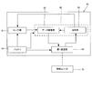
- FIG. 5 is a block diagram showing a control unit of the fluid leakage detection system according to the embodiment of the present invention.
- FIG. 1 is a schematic diagram illustrating a configuration of a fluid leak detection system according to an embodiment of the present invention.
- FIG. 2 is a partial cross-sectional view of the hydraulic cylinder according to the embodiment of the present invention.
- FIG. 3 is an enlarged sectional view of the hydraulic cylinder according to the embodiment of the present invention.
- FIG. 4 is a block diagram illustrating a measurement unit of the fluid leak detection system according to
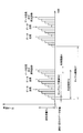
- FIG. 6 is a schematic graph for explaining the operating conditions of the measurement unit of the fluid leak detection system according to the embodiment of the present invention, in which the vertical axis represents the data capacity accumulated in the data storage unit, and the horizontal axis represents the data volume. Indicates time.
- FIG. 7 is a flowchart illustrating an abnormality diagnosis performed by the fluid leak detection system according to the embodiment of the present invention.
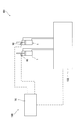
- FIG. 8 is a schematic diagram illustrating a configuration according to a modification of the fluid leak detection system according to the embodiment of the present invention.
- the fluid pressure system 101 is used for a construction machine as a fluid pressure driven machine, particularly for a hydraulic shovel.
- the fluid pressure system 101 drives the fluid pressure cylinders by controlling the flow of the working fluid supplied to and discharged from the plurality of fluid pressure cylinders.
- the fluid pressure system 101 includes a hydraulic cylinder 1 as a fluid pressure cylinder that drives a driven object (not shown) such as a boom, an arm, and a bucket, and a hydraulic oil supplied to and discharged from the hydraulic cylinder 1 ( Fluid pressure control device 102 that controls the operation of hydraulic cylinder 1 by controlling a working fluid), and fluid leakage detection that detects oil leakage through rod seal 11 (see FIG. 3) as a seal member provided in hydraulic cylinder 1. And a system 100.
- a hydraulic cylinder 1 as a fluid pressure cylinder that drives a driven object (not shown) such as a boom, an arm, and a bucket
- Fluid pressure control device 102 that controls the operation of hydraulic cylinder 1 by controlling a working fluid
- fluid leakage detection that detects oil leakage through rod seal 11 (see FIG. 3) as a seal member provided in hydraulic cylinder 1.
- a system 100 a system 100.
- the hydraulic cylinder 1 includes a cylindrical cylinder tube 2, a piston rod 3 inserted into the cylinder tube 2, and a piston 4 provided at a base end of the piston rod 3.
- the piston 4 is provided slidably along the inner peripheral surface of the cylinder tube 2.
- the interior of the cylinder tube 2 is partitioned by the piston 4 into a rod-side chamber (fluid pressure chamber) 2a and a non-rod-side chamber 2b.
- the tip of the piston rod 3 extends from the open end of the cylinder tube 2.
- a hydraulic source not shown
- the piston rod 3 moves with respect to the cylinder tube 2. This causes the hydraulic cylinder 1 to expand and contract.
- a cylinder head 5 through which the piston rod 3 is inserted is provided at the open end of the cylinder tube 2.
- the cylinder head 5 is fastened to the open end of the cylinder tube 2 using a plurality of bolts 6.
- the fluid pressure control device 102 controls the flow of hydraulic oil guided from the hydraulic pump (hydraulic source) to each hydraulic cylinder 1 to operate each hydraulic cylinder 1.
- the fluid leakage detection system 100 detects the occurrence of oil leakage (fluid leakage) in which hydraulic oil leaks from the rod side chamber 2 a through the space between the outer peripheral surface of the piston rod 3 and the inner peripheral surface of the cylinder head 5 in the hydraulic cylinder 1. .
- the fluid leak detection system 100 includes an annular gap (hereinafter, referred to as “annular”) between the outer peripheral surface of the piston rod 3 and the inner peripheral surface of the cylinder head 5 provided in the hydraulic cylinder 1.
- a notifying unit 90 see FIG. 5) for notifying the operator of the abnormality.
- the measurement unit 10 includes a rod seal 11 provided on the cylinder head 5 to seal an annular gap 8 between the outer peripheral surface of the piston rod 3 and the inner peripheral surface of the cylinder head 5, and a rod-side chamber.
- It includes a measuring unit 50 for measuring the state quantity of the hydraulic oil, and a housing 40 for housing the relief valve 30 and the measuring unit 50.
- a rod seal 11, a bush 13, a detection seal 12, and a dust seal 14 are interposed in this order from the base end (right side in FIG. 3) to the front end side (left side in FIG. 3). Is done.
- the rod seal 11, the bush 13, the detection seal 12, and the dust seal 14 are housed in annular grooves 5a, 5b, 5c, 5d formed on the inner periphery of the cylinder head 5, respectively.
- the bush 13 is supported so as to move in the axial direction of the cylinder tube 2 by sliding contact with the outer peripheral surface of the piston rod 3.
- the rod seal 11 is compressed between the outer periphery of the piston rod 3 and the annular groove 5 a on the inner periphery of the cylinder head 5, thereby sealing the annular gap 8.
- the rod seal 11 faces the rod side chamber 2a (see FIG. 2), and the rod seal 11 prevents the working oil in the rod side chamber 2a from leaking to the outside.
- the rod seal 11 is a so-called U packing.
- the dust seal 14 is provided on the cylinder head 5 so as to face the outside of the cylinder tube 2 and seals the annular gap 8.
- the dust seal 14 scrapes out dust adhering to the outer peripheral surface of the piston rod 3 to prevent dust from entering the cylinder tube 2 from outside.
- the detection seal 12 like the rod seal 11, is compressed between the outer periphery of the piston rod 3 and the annular groove 5c on the inner periphery of the cylinder head 5, thereby sealing the annular gap 8.
- the detection seal 12 is provided between the rod seal 11 and the dust seal 14 to define a detection space 20 together with the rod seal 11. That is, the detection space 20 is a space defined by the piston rod 3, the cylinder head 5, the rod seal 11, and the detection seal 12 (in this embodiment, the bush 13 in addition to this).
- the detection seal 12 is a U-packing like the rod seal 11.
- the communication passage 21 is formed over the cylinder head 5 and the housing 40 so as to communicate with the detection space 20.
- the communication path 21 has a first communication path 22 formed in the cylinder head 5 and opening to the detection space 20, and a second communication path 23 formed in the housing 40 and communicating with the first communication path 22.
- the working oil in the rod side chamber 2 a leaking from the rod seal 11 is guided to the communication passage 21 through the annular gap 8 and the detection space 20.
- the relief valve 30 opens when the pressure of the hydraulic oil in the second communication passage 23 reaches a predetermined pressure (relief pressure), and discharges the hydraulic oil in the detection space 20 to the outside through the second communication passage 23.
- a predetermined pressure relievef pressure
- the pressure in the detection space 20 is limited by the relief valve 30 to the relief pressure. Since the structure of the relief valve 30 can adopt a known configuration, detailed illustration and description are omitted.
- the housing 40 is fixed to the end of the cylinder head 5 by press fitting.
- the housing 40 is further formed with a sensor housing hole 41 for housing the measurement unit 50 and a valve housing hole 42 for housing the relief valve 30.
- the sensor housing hole 41 and the valve housing hole 42 communicate with the second communication passage 23, respectively, and the valve housing hole 42 communicates with the second communication passage 23 on the first communication passage 22 side (upstream side) of the sensor housing hole 41. are doing.
- the measuring unit 50 executes the measurement of the pressure as the state quantity of the hydraulic oil and the output of the measurement result to the control unit 70 under predetermined operating conditions.
- the measurement unit 50 measures the pressure and the temperature and outputs the measurement result based on the operation frequency based on the operation condition.
- the operation frequency includes a measurement frequency at which the measurement unit 50 measures the pressure and the temperature, and a transmission frequency at which the measurement result is transmitted from the measurement unit 50 to the control unit 70.
- the measurement unit 50 includes a sensor unit 51 that is a pressure-temperature sensor capable of measuring pressure and temperature, and a sensor controller that outputs a command signal to the sensor unit 51 and acquires a measurement result of the sensor unit 51.
- a sensor unit 51 that is a pressure-temperature sensor capable of measuring pressure and temperature
- a sensor controller that outputs a command signal to the sensor unit 51 and acquires a measurement result of the sensor unit 51.
- 60 a first communication unit 52 that transmits and receives signals to and from the control unit 70 by wireless communication
- a battery 54 that is a power source (power source) of the sensor unit 51, the sensor controller 60, and the first communication unit 52.
- the measuring unit 50 is configured by incorporating a sensor unit 51, a sensor controller 60, and a battery 54 in the same housing, respectively, and as shown in FIG. Part is accommodated.
- the measuring section 50 is fixed to the screw hole 24 communicating with the second communication passage 23 of the housing 40 by screwing.
- the sensor unit 51 measures the pressure and the temperature of the hydraulic oil guided from the detection space 20 through the first communication path 22 and the second communication path 23 (see FIG. 3). The operation of the sensor unit 51 will be described later in detail.
- the battery 54 is electrically connected to the sensor controller 60, the sensor unit 51, and the first communication unit 52.
- the sensor controller 60, the sensor unit 51, and the first communication unit 52 are operated by power supply from the battery 54, respectively. Further, the sensor controller 60 periodically acquires the voltage value of the battery 54.
- the sensor controller 60 is configured by a microcomputer including a CPU (central processing unit), a ROM (read only memory), a RAM (random access memory), and an I / O interface (input / output interface).
- the RAM stores data in the processing of the CPU
- the ROM stores a control program of the CPU in advance
- the I / O interface is used for inputting and outputting information to and from a connected device.
- the sensor controller 60 may be composed of a plurality of microcomputers.
- the sensor controller 60 is programmed so as to be able to execute at least processing necessary for control by the sensor controller 60 described in this specification. Note that the sensor controller 60 may be configured as a single device, or may be divided into a plurality of devices, and each control by the sensor controller 60 may be configured to perform distributed processing by the plurality of devices.
- the sensor controller 60 includes a command unit 61 that outputs a command signal to the sensor unit 51, and a data storage unit 62 that acquires and stores the measurement result of the sensor unit 51 and the remaining battery level of the battery 54.
- the sensor unit 51 Based on the command signal from the command unit 61, the sensor unit 51 operates under a predetermined operating condition (measurement frequency) to measure the pressure and the temperature of the detection space 20.
- the measurement result of the sensor unit 51 is input to the data storage unit 62.
- the data storage unit 62 stores the measurement result of the sensor unit 51 and the voltage value of the battery 54, and outputs the stored data to the control unit 70 under predetermined operating conditions (transmission frequency).
- the transmission frequency at which data is output from the data storage unit 62 can be changed according to a command signal from the command unit 61. Further, when the measurement result cannot be appropriately acquired from the sensor unit 51, the data storage unit 62 outputs data including an abnormal value as the measurement result.
- the first communication unit 52 is electrically connected to the sensor controller 60, and transmits and receives signals to and from the sensor controller 60. Further, the first communication unit 52 is configured to be capable of wireless communication with the control unit 70.
- the control unit 70 is disposed, for example, in a cab (cabin) of a construction machine. As illustrated in FIG. 5, the control unit 70 includes a second communication unit 71 that transmits and receives a signal by wireless communication with the first communication unit 52 of the measurement unit 50, and a measurement unit 50 of the measurement unit 10 through the second communication unit 71. And a controller 80 that transmits and receives signals to and from the controller 80.
- the controller 80 includes a microcomputer having a CPU (Central Processing Unit), a ROM (Read Only Memory), a RAM (Random Access Memory), and an I / O interface (I / O interface).
- the RAM stores data in the processing of the CPU
- the ROM stores a control program of the CPU in advance
- the I / O interface is used for inputting and outputting information to and from a connected device.
- the controller 80 may be composed of a plurality of microcomputers.
- the controller 80 is programmed so as to be able to execute at least a process required for control by the controller 80 described in this specification. Note that the controller 80 may be configured as a single device, or may be divided into a plurality of devices, and each control in the present embodiment may be configured to perform distributed processing by the plurality of devices.
- the controller 80 acquires the measurement result of the measurement unit 50, and determines whether or not oil leakage has occurred in the hydraulic cylinder 1 based on the measurement result of the measurement unit 50. Further, the controller 80 has an abnormality diagnosis function of diagnosing an abnormality of the measurement unit 50.
- the controller 80 includes a storage unit 81 that stores the measurement result of the measurement unit 50, a leak determination unit 82 that determines whether an oil leak has occurred according to the measurement result of the measurement unit 50, and data input from the measurement unit 50.
- a data acquisition determination unit 83 that determines whether or not the battery level has been reached, a remaining amount calculation unit 84 that calculates the remaining battery level of the battery 54 based on the voltage of the battery 54 and the temperature measured by the sensor unit 51, and
- a remaining battery level determining unit 85 that determines whether the battery 54 is in a low battery level state by comparing the remaining battery level with a predetermined battery remaining level threshold, and an abnormality diagnosing unit that diagnoses an abnormality of the measuring unit 50 86.
- Data transmitted from the sensor controller 60 of the measurement unit 50 (the pressure and temperature of the detection space 20 and the remaining amount of the battery 54) is stored in the storage unit 81 and is input to the leak determination unit 82.
- the leak determination unit 82 determines whether or not an oil leak has occurred in the hydraulic cylinder 1 based on the pressure measured by the sensor unit 51 of the measurement unit 10. The leak determination unit 82 determines the occurrence of an oil leak every time the measurement result of the measurement unit 10 is input.
- the data acquisition determination unit 83 determines whether data has been transmitted from the first communication unit 52 of the measurement unit 50 to the controller 80 via the second communication unit 71 at a predetermined timing.
- the remaining amount calculating unit 84 calculates the remaining amount of the battery 54 based on the voltage of the battery 54 included in the data transmitted from the measuring unit 50 and the temperature measured by the sensor unit 51. More specifically, the remaining amount calculation unit 84 calculates the remaining battery amount based on a map that is stored in the storage unit 81 in advance and indicates a relationship between the voltage of the battery 54 and the remaining battery amount.
- the relationship between the voltage of the battery 54 and the remaining battery level changes according to the ambient temperature of the battery 54. Further, the change in the ambient temperature affects the temperature measured by the sensor unit 51. For this reason, a plurality of maps are stored in the storage unit 81 in advance for each predetermined temperature range.
- the remaining amount calculation unit 84 reads a map corresponding to the temperature measured by the sensor unit 51 from the storage unit 81, and calculates the remaining battery amount based on the voltage of the battery 54 based on the map. Thus, the remaining battery power of the battery 54 is calculated.
- the battery remaining amount calculated by the remaining amount calculating unit 84 is input to the remaining amount determining unit 85.
- the remaining battery determination unit 85 determines that the battery 54 is in a low remaining charge state in which the battery 54 may run out of battery. If the amount is equal to or larger than the battery remaining amount threshold, it is determined that the battery is in the normal state.
- the remaining battery level threshold is determined according to the specifications of the components of the measurement unit 50 (the sensor unit 51, the sensor controller 60, the first communication unit 52), the operating conditions of the measurement unit 50, and the like. The determination result of the remaining amount determination unit 85 is input to the abnormality diagnosis unit 86.
- the abnormality diagnosis unit 86 diagnoses an abnormality of the measurement unit 50 based on the determination results of the data acquisition determination unit 83 and the remaining amount determination unit 85.
- the abnormalities that occur in the measuring unit 50 include “battery exhausted” in which the sensor unit 51 and the first communication unit 52 do not operate because the remaining battery power of the battery 54 is exhausted, and the first communication unit 52 or the second communication unit 71
- the controller 80 cannot acquire the pressure and temperature measured by the sensor unit 51 due to a failure or a radio wave failure. There is a “sensor failure” that cannot be measured.
- the abnormality diagnosis unit 86 Diagnose that a cut has occurred.
- the abnormality diagnosis unit 86 determines that a communication error has occurred. Is diagnosed as having occurred.
- the abnormality diagnostic unit 86 causes a sensor failure. Diagnose that there is. A more detailed description of the abnormality diagnosis will be described later.
- the notifying unit 90 is configured to be able to notify an operator of an oil leak occurring in the hydraulic cylinder 1 and an abnormality of the measuring unit 50 diagnosed by the abnormality diagnosing unit 86 of the controller 80.
- the notification unit 90 can provide notification in different modes according to the content (cause) of the abnormality.
- the notification unit 90 can have an arbitrary configuration such as a warning lamp, a warning buzzer, and a monitor (display).
- the sensor unit 51 measures the pressure and the temperature at a predetermined sampling period for each measurement cycle having a predetermined time length and repeated at predetermined time intervals.
- the data storage unit 62 transmits the data stored in the control unit 70 through the first communication unit 52. I do.
- the time length of the measurement cycle time from the start to the end of the measurement cycle
- the time interval from the start of a certain measurement cycle to the start of the next measurement cycle is “cycle interval CT”.
- sampling cycle SC sampling cycle SC
- transmission capacity Dc data capacity accumulated until the data storage unit 62 transmits (outputs) the measurement result
- the operating conditions of the measurement unit 50 include the measurement time Td, the sampling cycle SC, the cycle interval CT, which are the conditions under which the sensor unit 51 detects pressure and temperature, and the measurement result of the sensor unit 51.
- the transmission capacity Dc to be transmitted to the controller 80 is included.
- FIG. 6 is a schematic graph showing the relationship between time and the data capacity of measurement results stored in the data storage unit 62.
- the sensor unit 51 measures the pressure and the temperature in the detection space 20 for each sampling cycle SC during the measurement time Td, and measures the pressure and the temperature when the measurement time Td elapses from the start of the detection. To end. After completion of the measurement of the pressure and the temperature, the sensor unit 51 enters a standby state (sleep state) in which the pressure and the temperature are not measured.
- the measurement result of the sensor unit 51 is stored in the data storage unit 62.
- the data storage unit 62 outputs the stored data to the first communication unit 52 every time the measurement result is stored for the transmission capacity Dc.
- the data capacity of the measurement results for five measurements corresponds to the transmission capacity Dc.
- the first communication unit 52 wirelessly transmits the data output from the data storage unit 62 to the second communication unit 71 of the controller 80.
- the transmission frequency is determined according to the transmission capacity Dc at which data is transmitted from the data storage unit 62 of the sensor controller 60 to the controller 80 in the measurement unit 50.
- the data storage unit 62 deletes the stored data every time the stored data is output to the first communication unit 52.
- the present invention is not limited to this. May be.
- the sensor unit 51 measures the pressure and the temperature in the detection space 20 intermittently, not always (continuously). Further, the measurement result of the sensor unit 51 is not immediately transmitted to the controller 80, but is transmitted to the controller 80 when the transmission capacity Dc is accumulated in the data storage unit 62. That is, the measurement result of the sensor unit 51 is intermittently transmitted to the controller 80. Since the measurement by the sensor unit 51 and the transmission of the measurement result from the data storage unit 62 are performed intermittently, power consumption can be reduced. The operating conditions of the measuring unit 50 can be changed by a signal from the controller 80, and the sensor unit 51 and the data storage unit 62 can also execute continuous measurement and output of measurement results (data transmission), respectively. .
- the voltage of the battery 54 is stored in the data storage unit 62 and transmitted to the controller 80 through the first communication unit 52 together with the measurement result of the sensor unit 51.
- the voltage of the battery 54 may be a voltage that is transmitted to the controller 80 at the time of the last data transmission in the measurement cycle in which the abnormality diagnosis is performed as described later, and may not be transmitted to the controller 80 every time. Good.
- the oil pressure of the rod side chamber 2 a is guided into the detection space 20 beyond the rod seal 11. Therefore, the pressure and temperature of the detection space 20 increase with the deterioration of the rod seal 11.
- the pressure in the detection space 20 is measured by the measurement unit 50 of the measurement unit 10, and the controller 80 of the control unit 70 determines whether or not an oil leak has occurred based on the measurement result. An oil leak in the cylinder 1 is detected.
- “deterioration” of the rod seal 11 includes abrasion and damage. The wear is caused by a steady load such as a reciprocating motion of the piston rod 3 and indicates deterioration due to the life. Damage refers to deterioration caused by accidental load due to an accident or the like.
- the determination of the oil leak is performed based on the pressure in the detection space 20.
- the leak determination unit 82 of the controller 80 acquires the maximum pressure value as pressure data from the transmitted data group.
- the leak determination unit 82 compares the maximum pressure value with a predetermined determination threshold, and determines that an oil leak has occurred if the maximum pressure value is equal to or greater than the determination threshold.
- the leak determining unit 82 determines that an oil leak has occurred, the determination result is transmitted to the notifying unit 90, and the occurrence of the oil leak is notified to the worker. In this way, oil leakage in the hydraulic cylinder 1 is detected.
- the leak determination unit 82 determines that no oil leakage has occurred.
- the phrase “no oil leakage has occurred” in the present specification does not mean exactly, but only means that the hydraulic oil has not leaked into the detection space 20 at all beyond the rod seal 11. Absent. For example, even when the hydraulic oil leaks from the rod side chamber 2a into the detection space 20, if the deterioration (wear / damage) of the rod seal 11 is tolerable, the leak determination unit 82 sets “ No oil leakage has occurred ". That is, "oil leakage has occurred” refers to a state in which the deterioration (wear / damage) of the rod seal 11 has exceeded an allowable range. Therefore, the determination threshold is set according to the degree of deterioration (wear / damage) of the rod seal 11 that is allowed.
- the pressure data used to determine the oil leak is not limited to the maximum pressure value, but may be other data.
- the pressure data may be one measurement value included in a transmitted data group such as a minimum pressure value or a median value, or a value calculated by calculating a measurement value such as an average value. Is also good. That is, the pressure data includes the measured value of the pressure itself measured by the sensor unit 51 and the value obtained from the measured value.
- the controller 80 executes an abnormality diagnosis for diagnosing whether an abnormality such as “battery exhaustion”, “communication abnormality”, and “sensor failure” has occurred in the measurement unit 50.
- the controller 80 executes the process shown in FIG. 7 at a predetermined cycle. Specifically, as shown in FIG. 6, the controller 80 performs the abnormality diagnosis at the last data transmission timing in each measurement cycle.
- the execution cycle of the abnormality diagnosis is not limited to this, and can be set arbitrarily.
- Step 10 it is determined whether or not the data of the measurement unit 50 has been input to the controller 80 at a predetermined timing.
- the predetermined timing is within a predetermined time range R (see FIG. 6) including the end of the measurement cycle (the last data transmission).
- the process proceeds to step S11.
- step 11 the remaining battery level of the battery 54 is calculated from the voltage of the battery 54 using a map corresponding to the temperature in the detection space 20.
- step 12 the remaining battery level of the battery 54 is compared with the remaining battery threshold to determine whether the battery 54 is in a low remaining battery state. If the remaining battery level of the battery 54 is less than the remaining battery level threshold, it is determined that the battery 54 is in the low remaining battery level state, and the process proceeds to step 13, where the battery exhaustion flag is enabled (ON). If the remaining battery level of the battery 54 is greater than or equal to the remaining battery threshold, the battery 54 is determined to be in the normal state, and the process proceeds to step 14, where the dead battery flag is disabled (OFF).
- step 15 it is determined whether an abnormal value is included in the measurement result of the sensor unit 51 included in the data input to the controller 80.
- the measurement unit 50 (the data storage unit 62) transmits data including an abnormal value as a measurement result to the controller 80. Therefore, by determining whether or not the measurement result of the sensor unit 51 includes an abnormal value, it is possible to determine whether or not a sensor failure has occurred.
- step 15 if the measurement result does not include an abnormal value, it is determined in step 16 that the measurement unit 50 is normal, and the process ends.
- step 15 If it is determined in step 15 that an abnormal value is included in the measurement result, it is diagnosed in step 17 that a sensor failure has occurred.
- step 10 If it is determined in step 10 that data has not been input to the controller 80, it is diagnosed in steps 18 to 20 whether the measuring unit 50 has run out of battery or communication error.
- step 18 it is determined whether the battery exhaustion flag is ON.
- steps 12 and 13 of the abnormality diagnosis executed last time if the battery 54 is in the low-remaining state and the battery exhaustion flag is set to ON, the current abnormality diagnosis proceeds from step 18 to step 19, 50 is diagnosed as dead battery.
- the out-of-battery flag is set to OFF in the abnormality diagnosis executed last time, the process proceeds from step 18 to step 20 in this abnormality diagnosis, and it is diagnosed that the communication is abnormal, not battery exhaustion.
- the abnormality diagnosis first, it is determined whether or not data has been transmitted (input) from the measurement unit 50 to the controller 80. It is diagnosed whether it is “failure”, “battery exhaustion” or "communication abnormality”.
- the remaining battery level of the battery 54 is calculated in a state where data is input to the controller 80 (in other words, in a state where neither “out of battery” nor “abnormal communication” has occurred).
- the disconnection flag is set to ON. Thereafter, when data is no longer input to the controller 80, it is determined whether the measuring unit 50 is "out of battery” or "communication abnormal” using the battery exhaustion flag. As described above, by setting the battery exhaustion flag in a state where data is being input to the controller 80, it is possible to determine whether “battery exhaustion” or “communication abnormality” has occurred when data is no longer input to the controller 80. can do.
- the sensor controller 60 transmits a measurement result including an abnormal value to the controller 80.
- the abnormality diagnosis it is determined whether the measurement unit 50 is “normal” or “sensor failure” by determining whether an abnormal value is included in the measurement result.
- the fluid pressure system 101 includes a plurality of (two in the figure) hydraulic cylinders 1, and each hydraulic cylinder 1 is provided with the measurement unit 10.
- the controller 80 is commonly used, and the measuring units 10 of the respective hydraulic cylinders 1 operate under the same operating conditions.
- measurement of another hydraulic cylinder 1 is performed as a timing at which the controller 80 determines whether data has been acquired.
- the time may be within a time range including the timing at which the controller 80 acquires data from the measurement unit 50 of the unit 10. Even in this case, the same operation and effect as those of the above embodiment can be obtained.
- the sensor unit 51 measures the pressure as the state quantity of the hydraulic oil
- the leak determination unit 82 of the controller 80 determines the leakage of the hydraulic oil based on the pressure measured by the sensor unit 51.
- the sensor unit 51 may measure a state quantity other than the pressure, and the leak determination unit 82 may determine the leakage of the hydraulic oil based on the state quantity measured by the sensor unit 51.
- the sensor unit 51 may measure the dielectric constant of the hydraulic oil guided to the detection space 20 as a state quantity, and the leak determination unit 82 may determine the leakage of the hydraulic oil based on the dielectric constant.
- the sensor unit 51 is a pressure / temperature sensor capable of measuring pressure and temperature. Oil leakage is determined based on the pressure measured by the sensor unit 51, and the remaining battery level of the battery 54 is calculated based on the temperature (and the voltage of the battery 54) measured by the sensor unit 51.
- the measurement unit 50 includes a sensor unit 51 that measures a state quantity of the hydraulic oil in order to determine a leakage of the hydraulic oil, a temperature sensor that measures a temperature in order to calculate the remaining battery level of the battery 54, May be separately provided.
- the measurement unit 50 does not necessarily need to be configured to be able to measure the temperature, and may calculate the remaining battery level of the battery 54 without being based on the temperature.
- the fluid leakage detection system 100 determines whether data has been transmitted (input) from the measurement unit 50 to the controller 80, and if no data has been input, determines whether the battery 54 is in a low battery state. Is determined, the measurement unit 50 is diagnosed as “battery exhausted” or “communication abnormality”. When data is input from the measurement unit 50 to the controller 80, whether the measurement result of the measurement unit 50 is “normal” is determined by determining whether an abnormal value is included in the measurement result. Is diagnosed as "sensor failure”. As described above, in the fluid leak detection system 100, it is possible to diagnose the abnormality of the measuring unit 50, and it is possible to more reliably detect the oil leak.
- the remaining battery level of the battery 54 is calculated based on a plurality of maps stored in the storage unit 81 corresponding to the temperature. Thus, the remaining battery level of the battery 54 can be accurately calculated.
- a fluid leak detection system 100 for detecting a leaked hydraulic oil includes a measurement unit 10 provided in the hydraulic cylinder 1 for measuring a state quantity of the hydraulic oil leaking through an annular gap 8 between the piston rod 3 and the cylinder head 5. And a controller 80 for acquiring a measurement result of the measurement unit 10.
- the measurement unit 10 includes a rod seal 11 provided in the cylinder head 5 and sealing the annular gap 8 between the piston rod 3 and the cylinder head 5.
- the controller 80 includes a sensor unit 51 that measures a state quantity, and a first communication unit 52 that transmits data including a measurement result of the sensor unit 51 and a voltage of the battery 54 to the controller 80 by wireless communication.
- a data acquisition determining unit 83 that determines whether data has been input from the battery 50, a remaining amount calculating unit 84 that calculates the remaining battery amount based on the voltage of the battery 54, and a remaining battery amount calculated by the remaining amount calculating unit 84.
- abnormality diagnosis unit 8 Indicates that the battery 54 has run out of power if the data acquisition determining unit 83 determines that data has not been acquired and the remaining amount determining unit 85 determines that the battery 54 is in a low remaining state. If the data acquisition determination unit 83 determines that data has not been acquired and the remaining amount determination unit 85 determines that the battery 54 is not in the low remaining amount state, the first communication It is diagnosed that a communication error has occurred in the unit 52.
- the data acquisition determining unit 83 determines that data has not been acquired when there is no data input at a predetermined timing.
- the measuring unit 50 measures the state quantity of the hydraulic oil in each measurement cycle having a predetermined time length and repeated at predetermined time intervals, and the predetermined timing is determined in the measurement cycle. It is within a predetermined time range including the end time.
- the fluid leak detection system 100 includes a plurality of measurement units 10 respectively provided in the plurality of hydraulic cylinders 1, and the predetermined timing includes a predetermined time including a time when data is acquired from the measurement unit 50 of another measurement unit 10. Within the time range.
- the measuring unit 50 further includes a sensor controller 60 that acquires the measurement result of the sensor unit 51 and outputs the measurement result to the first communication unit 52. If the state quantity cannot be measured, the measurement result including the abnormal value is output to the first communication unit 52, and the abnormality diagnosis unit 86 determines that the communication from the first communication unit 52 has been executed by the communication determination unit. If the measurement result of the sensor unit 51 includes an abnormal value, it is diagnosed that the sensor unit 51 is malfunctioning.
- the measuring unit 50 is configured to be capable of measuring the temperature
- the remaining amount calculating unit 84 determines the remaining battery level of the battery 54 based on the temperature measured by the measuring unit 50 and the voltage of the battery 54. Calculate the amount.
- the remaining battery level of the battery 54 is calculated in consideration of the temperature effect, the remaining battery level of the battery 54 can be accurately calculated.
Landscapes
- Engineering & Computer Science (AREA)
- Physics & Mathematics (AREA)
- General Engineering & Computer Science (AREA)
- Mechanical Engineering (AREA)
- Fluid Mechanics (AREA)
- General Physics & Mathematics (AREA)
- Chemical & Material Sciences (AREA)
- Electrochemistry (AREA)
- General Chemical & Material Sciences (AREA)
- Chemical Kinetics & Catalysis (AREA)
- Manufacturing & Machinery (AREA)
- Analytical Chemistry (AREA)
- Fluid-Pressure Circuits (AREA)
- Examining Or Testing Airtightness (AREA)
- Tests Of Electric Status Of Batteries (AREA)
- Secondary Cells (AREA)
Abstract
流体漏れ検出システム(100)は、油圧シリンダ(1)の作動油の漏れを検出するための測定ユニット(10)と、測定ユニット(10)の測定結果を取得するコントローラ(80)と、を備え、コントローラ(80)は、測定ユニット(10)のデータが取得されていないと判定され、かつ、測定ユニット(10)のバッテリ(54)が残量低下状態であると判定された場合には、バッテリ(54)にバッテリ切れが生じていると診断し、測定ユニット(10)のデータが取得されていないと判定され、かつ、バッテリ(54)が残量低下状態ではないと判定された場合には、測定ユニット(10)の第1通信部(52)に通信異常が発生していると診断する。
Description
本発明は、流体漏れ検出システムに関するものである。
JP2006-28744Aには、流体圧装置に供給される作動流体の状態を検出する流体検出器として、作動流体の圧力を検出する圧力検出器が開示されている。このような圧力検出器は、作動流体に接触する検出部と、検出部で検出された値を外部に出力する出力部と、を有する。
流体圧シリンダにおける流体漏れを検出する流体漏れ検出システムとして、JP2006-28744Aに開示されるような流体検出器を流体圧シリンダに取り付け、流体検出器の測定結果に基づいてコントローラが作動流体の漏れを判定することが考えられる。
このような場合、流体検出器に異常が生じるとコントローラによる作動流体の漏れの判定ができないため、作動流体の漏れを精度よく検出するためには、流体漏れ検出システムの異常の診断が求められる。
本発明は、異常の診断が可能な流体漏れ検出システムを提供することを目的とする。
本発明のある態様によれば、流体漏れ検出システムは、流体圧シリンダに設けられ、ピストンロッドとシリンダヘッドとの間の隙間を通じて漏れる作動流体の状態量を測定する測定ユニットと、測定ユニットの測定結果を取得するコントローラと、を備え、測定ユニットは、シリンダヘッドに設けられピストンロッドとシリンダヘッドとの間の隙間を封止するロッドシールと、ロッドシールから漏れる作動流体が導かれる検出空間と、検出空間における作動流体の状態量の測定と測定結果の出力とを所定の作動条件で実行する測定部と、を有し、測定部は、電源としてのバッテリと、検出空間における作動流体の状態量を測定するセンサ部と、センサ部の測定結果及びバッテリの電圧を含むデータをコントローラへ無線通信により送信する通信部と、を有し、コントローラは、測定部からデータが入力されたか否かを判定するデータ取得判定部と、バッテリの電圧に基づき電池残量を算出する残量算出部と、残量算出部が算出した電池残量と所定の電池残量閾値とを比較して、バッテリが残量低下状態であるか否かを判定する残量判定部と、測定部の異常を診断する異常診断部と、を有し、異常診断部は、データ取得判定部によってデータが取得されていないと判定され、かつ、残量判定部によってバッテリが残量低下状態であると判定された場合には、バッテリにバッテリ切れが生じていると診断し、データ取得判定部によってデータが取得されていないと判定され、かつ、残量判定部によってバッテリが残量低下状態ではないと判定された場合には、通信部に通信異常が発生していると診断する。
以下、図面を参照して、本発明の実施形態に係る流体漏れ検出システム100について説明する。
まず、図1を参照して、流体漏れ検出システム100を備える流体圧システム101の全体構成について説明する。
流体圧システム101は、流体圧駆動機械としての建設機械、特に油圧ショベルに用いられる。流体圧システム101は、複数の流体圧シリンダに給排される作動流体の流れを制御して、流体圧シリンダを駆動させる。
流体圧システム101は、図1に示すように、ブーム,アーム,及びバケットといった駆動対象(図示省略)を駆動する流体圧シリンダとしての油圧シリンダ1と、油圧シリンダ1に給排される作動油(作動流体)を制御して油圧シリンダ1の作動を制御する流体圧制御装置102と、油圧シリンダ1に設けられるシール部材としてのロッドシール11(図3参照)を通じた油漏れを検出する流体漏れ検出システム100と、を備える。
図2に示すように、油圧シリンダ1は、筒状のシリンダチューブ2と、シリンダチューブ2に挿入されるピストンロッド3と、ピストンロッド3の基端に設けられるピストン4と、を備える。ピストン4は、シリンダチューブ2の内周面に沿って摺動自在に設けられる。シリンダチューブ2の内部は、ピストン4によってロッド側室(流体圧室)2aと反ロッド側室2bとに区画される。
ピストンロッド3は、先端がシリンダチューブ2の開口端から延出している。図示しない油圧源からロッド側室2a又は反ロッド側室2bに選択的に作動油が導かれると、ピストンロッド3は、シリンダチューブ2に対して移動する。これにより、油圧シリンダ1は伸縮作動する。
シリンダチューブ2の開口端には、ピストンロッド3が挿通するシリンダヘッド5が設けられる。シリンダヘッド5は、複数のボルト6を用いてシリンダチューブ2の開口端に締結される。
流体圧制御装置102は、公知の構成を採用できるため、詳細な図示及び説明を省略する。流体圧制御装置102は、油圧ポンプ(油圧源)から各油圧シリンダ1に導かれる作動油の流れを制御して、各油圧シリンダ1を作動させる。
次に、流体漏れ検出システム100について、具体的に説明する。
流体漏れ検出システム100は、油圧シリンダ1において、ロッド側室2aからピストンロッド3の外周面とシリンダヘッド5の内周面との間を通じて作動油が漏れ出す油漏れ(流体漏れ)の発生を検出する。
流体漏れ検出システム100は、主に図1,3に示すように、油圧シリンダ1に設けられピストンロッド3の外周面とシリンダヘッド5の内周面との間の環状の隙間(以下、「環状隙間8」と称する。)から漏れ出す作動油の状態量を測定する測定ユニット10と、測定ユニット10の測定結果に基づき油圧シリンダ1における油漏れの発生を判定する制御ユニット70と、測定ユニット10の異常を作業者に報知する報知部90(図5参照)と、を備える。
測定ユニット10は、図3に示すように、シリンダヘッド5に設けられピストンロッド3の外周面とシリンダヘッド5の内周面との間の環状隙間8を封止するロッドシール11と、ロッド側室2aからロッドシール11を超えて漏れる作動油が導かれる検出空間20と、シリンダヘッド5に設けられて環状隙間8を封止し、ロッドシール11と共に検出空間20を区画する検出シール12と、検出空間20に連通する連通路21と、連通路21の圧力がリリーフ圧に達すると開弁して連通路21の圧力を逃がすリリーフ弁30と、ロッドシール11を超えて検出空間20に漏れ出した作動油の状態量を測定する測定部50と、リリーフ弁30及び測定部50を収容するハウジング40と、を備える。
シリンダヘッド5の内周には、ロッドシール11、ブッシュ13、検出シール12、ダストシール14が、基端側(図3中右側)から先端側(図3中左側)に向かってこの順で介装される。ロッドシール11、ブッシュ13、検出シール12、ダストシール14は、それぞれシリンダヘッド5の内周に形成される環状溝5a,5b,5c,5dに収容される。
ブッシュ13がピストンロッド3の外周面に摺接することにより、ピストンロッド3がシリンダチューブ2の軸方向に移動するように支持される。
ロッドシール11は、ピストンロッド3の外周とシリンダヘッド5の内周の環状溝5aとの間で圧縮されており、これにより環状隙間8を封止する。ロッドシール11は、ロッド側室2a(図2参照)に臨んでおり、ロッドシール11によって、ロッド側室2a内の作動油が外部に漏れることが防止される。ロッドシール11は、いわゆるUパッキンである。
ダストシール14は、シリンダチューブ2の外部に臨むようにシリンダヘッド5に設けられて、環状隙間8を封止する。ダストシール14は、ピストンロッド3の外周面に付着するダストをかき出して、外部からシリンダチューブ2内へのダストの侵入を防止する。
検出シール12は、ロッドシール11と同様に、ピストンロッド3の外周とシリンダヘッド5の内周の環状溝5cとの間で圧縮されており、これにより環状隙間8を封止する。検出シール12は、ロッドシール11とダストシール14の間に設けられて、ロッドシール11と共に検出空間20を区画する。つまり、検出空間20は、ピストンロッド3、シリンダヘッド5、ロッドシール11、及び検出シール12(本実施形態では、これに加えてブッシュ13)によって区画される空間である。検出シール12は、ロッドシール11と同様、Uパッキンである。
連通路21は、検出空間20に連通するように、シリンダヘッド5及びハウジング40にわたって形成される。連通路21は、シリンダヘッド5に形成され検出空間20に開口する第1連通路22と、ハウジング40に形成され第1連通路22に連通する第2連通路23と、を有する。連通路21には、ロッドシール11から漏れ出すロッド側室2aの作動油が環状隙間8及び検出空間20を通じて導かれる。
リリーフ弁30は、第2連通路23における作動油の圧力が所定の圧力(リリーフ圧)に達すると開弁し、第2連通路23を通じて検出空間20内の作動油を外部に排出する。これにより、検出空間20内の圧力は、リリーフ弁30によってリリーフ圧に制限される。リリーフ弁30の構造は、公知の構成を採用することができるため、詳細な図示及び説明は省略する。
ハウジング40は、シリンダヘッド5の端部に圧入により固定される。ハウジング40には、測定部50を収容するセンサ収容穴41と、リリーフ弁30を収容するバルブ収容穴42と、がさらに形成される。センサ収容穴41及びバルブ収容穴42は、それぞれ第2連通路23に連通し、バルブ収容穴42がセンサ収容穴41よりも第1連通路22側(上流側)において第2連通路23に連通している。
測定部50は、作動油の状態量としての圧力の測定と制御ユニット70への測定結果の出力とを所定の作動条件により実行する。測定部50は、作動条件に基づいた作動頻度により、圧力及び温度の測定と測定結果の出力とを実行する。作動頻度とは、測定部50が圧力及び温度を測定する測定頻度と、測定部50から制御ユニット70へ測定結果が送信される送信頻度と、を含むものである。
測定部50は、図4に示すように、圧力及び温度を測定可能な圧力温度センサであるセンサ部51と、センサ部51に指令信号を出力すると共にセンサ部51の測定結果を取得するセンサコントローラ60と、無線通信により制御ユニット70と信号の送受信を行う第1通信部52と、センサ部51、センサコントローラ60、及び第1通信部52の電源(動力源)であるバッテリ54と、を有する。
測定部50は、センサ部51、センサコントローラ60、及びバッテリ54がそれぞれ同一の筐体内に組み込まれて構成されており、図3に示すように、ハウジング40に形成されるセンサ収容穴41に一部が収容される。また、測定部50は、ハウジング40の第2連通路23に連通するねじ孔24に螺合により固定される。
センサ部51は、第1連通路22及び第2連通路23(図3参照)を通じて検出空間20から導かれる作動油の圧力及び温度を測定する。センサ部51の作動については、後に詳細に説明する。
バッテリ54は、センサコントローラ60、センサ部51、及び第1通信部52に電気的に接続される。センサコントローラ60、センサ部51、及び第1通信部52は、バッテリ54からの給電によりそれぞれ作動する。また、センサコントローラ60は、バッテリ54の電圧値を定期的に取得する。
センサコントローラ60は、CPU(中央演算処理装置)、ROM(リードオンリメモリ)、RAM(ランダムアクセスメモリ)、及びI/Oインターフェース(入出力インターフェース)を備えたマイクロコンピュータで構成される。RAMはCPUの処理におけるデータを記憶し、ROMはCPUの制御プログラム等を予め記憶し、I/Oインターフェースは接続された機器との情報の入出力に使用される。センサコントローラ60は、複数のマイクロコンピュータで構成されてもよい。センサコントローラ60は、少なくとも、本明細書に記載されるセンサコントローラ60による制御のために必要な処理を実行可能となるようにプログラムされている。なお、センサコントローラ60は一つの装置として構成されていても良いし、複数の装置に分けられ、センサコントローラ60による各制御を当該複数の装置で分散処理するように構成されていてもよい。
センサコントローラ60は、センサ部51に指令信号を出力する指令部61と、センサ部51の測定結果及びバッテリ54の電池残量を取得し蓄えるデータ保管部62と、を有する。
指令部61からの指令信号に基づき、センサ部51は所定の作動条件(測定頻度)で作動して、検出空間20圧力及び温度を測定する。センサ部51の測定結果は、データ保管部62に入力される。
データ保管部62は、センサ部51の測定結果とバッテリ54の電圧値を蓄積し、蓄積されたデータを所定の作動条件(送信頻度)で制御ユニット70に向け出力する。データ保管部62からデータを出力する送信頻度は、指令部61の指令信号に応じて変更可能である。また、データ保管部62は、センサ部51から適切に測定結果を取得できない場合、異常値を含むデータを測定結果として出力する。
第1通信部52は、センサコントローラ60に電気的に接続され、センサコントローラ60との間で信号の送受信を行う。また、第1通信部52は、制御ユニット70との間で無線通信可能に構成される。
制御ユニット70は、例えば、建設機械の運転室(キャビン)内に配置される。制御ユニット70は、図5に示すように、測定部50の第1通信部52と無線通信により信号の送受信を行う第2通信部71と、第2通信部71を通じて測定ユニット10の測定部50との間で信号の送受信が行われるコントローラ80と、を備える。
コントローラ80は、CPU(中央演算処理装置)、ROM(リードオンリメモリ)、RAM(ランダムアクセスメモリ)、及びI/Oインターフェース(入出力インターフェース)を備えたマイクロコンピュータで構成される。RAMはCPUの処理におけるデータを記憶し、ROMはCPUの制御プログラム等を予め記憶し、I/Oインターフェースは接続された機器との情報の入出力に使用される。コントローラ80は、複数のマイクロコンピュータで構成されてもよい。コントローラ80は、少なくとも、本明細書に記載されるコントローラ80による制御のために必要な処理を実行可能となるようにプログラムされている。なお、コントローラ80は一つの装置として構成されていても良いし、複数の装置に分けられ、本実施形態における各制御を当該複数の装置で分散処理するように構成されていてもよい。
コントローラ80は、測定部50の測定結果を取得し、測定部50の測定結果に基づき油圧シリンダ1において油漏れが発生しているか否かを判定する。また、コントローラ80は、測定部50の異常を診断する異常診断機能を有する。
コントローラ80は、測定部50の測定結果を記憶する記憶部81と、測定部50の測定結果に応じて油漏れの発生の有無を判定する漏れ判定部82と、測定部50からデータが入力されたか否かを判定するデータ取得判定部83と、バッテリ54の電圧及びセンサ部51が測定した温度に基づきバッテリ54の電池残量を算出する残量算出部84と、残量算出部84が算出した電池残量と所定の電池残量閾値とを比較して、バッテリ54が残量低下状態であるか否かを判定する残量判定部85と、測定部50の異常を診断する異常診断部86と、を有する。
測定部50のセンサコントローラ60から送信されるデータ(検出空間20の圧力及び温度、バッテリ54の電池残量)は、記憶部81に記憶されると共に、漏れ判定部82に入力される。
漏れ判定部82は、測定ユニット10のセンサ部51が測定する圧力に基づき、油圧シリンダ1において油漏れが発生しているか否かを判定する。漏れ判定部82は、測定ユニット10の測定結果が入力されるごとに油漏れの発生を判定する。
データ取得判定部83は、所定のタイミングにおいて、測定部50の第1通信部52から第2通信部71を通じてコントローラ80にデータが送信されたか否かを判定する。
残量算出部84は、測定部50から送信されるデータに含まれるバッテリ54の電圧及びセンサ部51が測定した温度に基づき、バッテリ54の電池残量を算出する。具体的に説明すると、残量算出部84は、記憶部81に予め記憶されるバッテリ54の電圧と電池残量との関係を示すマップに基づき、電池残量を算出する。ここで、バッテリ54の電圧と電池残量との関係は、バッテリ54の周辺温度に応じて変化する。また、周辺温度の変化は、センサ部51が測定する温度に影響する。このため、記憶部81には、所定の温度範囲ごとに複数のマップが予め記憶される。残量算出部84は、センサ部51が測定した温度に対応するマップを記憶部81から読み込み、バッテリ54の電圧から当該マップに基づいて電池残量を算出する。このようにして、バッテリ54の電池残量が算出される。残量算出部84が算出した電池残量は、残量判定部85に入力される。
残量判定部85は、残量算出部84が算出した電池残量が電池残量閾値未満であれば、バッテリ54がバッテリ切れとなるおそれがある残量低下状態であると判定し、電池残量が電池残量閾値以上であれば通常状態であると判定する。電池残量閾値は、測定部50の各構成(センサ部51、センサコントローラ60、第1通信部52)の仕様や、測定部50の作動条件等に応じて定められる。残量判定部85の判定結果は、異常診断部86に入力される。
異常診断部86は、データ取得判定部83と残量判定部85の判定結果に基づいて、測定部50の異常を診断する。測定部50に生じる異常としては、バッテリ54の電池残量がなくなってセンサ部51及び第1通信部52が作動しない状態である「バッテリ切れ」、第1通信部52又は第2通信部71の故障や電波不良などにより、コントローラ80がセンサ部51が測定した圧力及び温度を取得できない状態である「通信異常」、及びセンサ部51がバッテリ切れ以外の原因で適切に作動せず圧力及び温度を測定できない状態である「センサ故障」がある。
異常診断部86は、データ取得判定部83によってデータが取得されていないと判定された場合において、残量判定部85によりバッテリ54が残量低下状態であると判定されると、バッテリ54に電池切れが生じていると診断する。また、異常診断部86は、データ取得判定部83によってデータが取得されていないと判定された場合において、残量判定部85によりバッテリ54が残量低下状態ではないと判定されると、通信異常が発生していると診断する。さらに、異常診断部86は、データ取得判定部83によってデータが取得したと判定された場合において、センサ部51の測定結果に異常値が含まれていると判定されると、センサ故障が生じていると診断する。異常診断のより詳細な説明は、後述する。
報知部90は、油圧シリンダ1で生じる油漏れと、コントローラ80の異常診断部86によって診断される測定部50の異常と、を、作業者に報知可能に構成される。報知部90は、異常の内容(原因)に応じて異なる態様で報知することができる。報知部90は、例えば、警告ランプ、警告ブザー、モニタ(表示器)など、任意の構成とすることができる。
次に、流体漏れ検出システム100の作用について説明する。
まず、測定ユニット10の測定部50の作動について、具体的に説明する。
センサ部51は、所定の時間長を有し所定の時間間隔で繰り返される測定サイクルごとに、所定のサンプリング周期によって圧力及び温度を測定する。データ保管部62は、蓄積されたデータ(センサ部51の測定結果及びバッテリ54の電池残量)が所定のデータ容量に達すると、第1通信部52を通じて制御ユニット70に蓄積されたデータを送信する。以下では、測定サイクルの時間長(測定サイクルの開始から終了までの時間)を「測定時間Td」、ある測定サイクルの開始から次回の測定サイクルの開始までの時間間隔を「サイクル間隔CT」とする。また、センサ部51のサンプリング周期を「サンプリング周期SC」、データ保管部62が測定結果を送信(出力)するまでに蓄積するデータ容量を「送信容量Dc」とする。測定部50の作動条件とは、センサ部51が圧力及び温度を検出する条件である測定時間Td、サンプリング周期SC、サイクル間隔CT、及びセンサ部51の測定結果をデータ保管部62が制御ユニット70のコントローラ80に送信する送信容量Dcが含まれる。
図6は、時間とデータ保管部62に蓄積される測定結果のデータ容量との関係を示す模式的なグラフ図である。図6に示すように、センサ部51は、測定時間Tdの間、サンプリング周期SCごとに検出空間20内の圧力及び温度を測定し、検出開始から測定時間Tdが経過すると、圧力及び温度の測定を終了する。圧力及び温度の測定の終了後は、センサ部51は、圧力及び温度を測定しない待機状態(スリープ状態)となる。
センサ部51の測定結果は、データ保管部62に蓄積される。データ保管部62は、送信容量Dc分だけ測定結果が蓄積されるごとに、蓄積されたデータを第1通信部52に出力する。図6では、5回分の測定結果のデータ容量が送信容量Dcに相当する。第1通信部52は、データ保管部62から出力されたデータをコントローラ80の第2通信部71に無線送信する。送信頻度は、測定部50におけるセンサコントローラ60のデータ保管部62からコントローラ80にデータが送信される送信容量Dcに応じて定められる。
なお、図6に示すように、データ保管部62は、蓄積されたデータを第1通信部52に出力するごとに蓄積されたデータを消去するが、これに限らず、データを蓄積し続けるものでもよい。
このように、センサ部51は、検出空間20内の圧力及び温度を常時(連続的に)測定するのではなく間欠的に測定する。また、センサ部51の測定結果は、直ちにコントローラ80に送信されるものではなく、送信容量Dcだけデータ保管部62に蓄積されると、コントローラ80に送信される。つまり、センサ部51の測定結果は、間欠的にコントローラ80に送信される。センサ部51による測定とデータ保管部62からの測定結果の送信が、それぞれ間欠的に実行されるため、消費電力を低減することができる。なお、測定部50の作動条件は、コントローラ80からの信号により変更可能であり、センサ部51及びデータ保管部62は、それぞれ連続的な測定と測定結果の出力(データ送信)も実行可能である。
また、バッテリ54の電圧は、データ保管部62に蓄積され、センサ部51の測定結果と共に第1通信部52を通じてコントローラ80へ送信される。なお、バッテリ54の電圧は、後述するように異常診断が実行される測定サイクル内の最後のデータ送信の際にコントローラ80に送信されるものであればよく、コントローラ80に毎回送信されなくてもよい。
次に、コントローラ80による油漏れの判定について説明する。
油圧シリンダ1のロッドシール11の劣化が進行すると、ロッド側室2aの油圧がロッドシール11を超えて検出空間20内に導かれる。よって、ロッドシール11の劣化に伴い検出空間20の圧力及び温度は上昇する。流体漏れ検出システム100では、検出空間20内の圧力を測定ユニット10の測定部50により測定し、測定結果に基づいて制御ユニット70のコントローラ80で油漏れの発生の有無を判定することにより、油圧シリンダ1における油漏れが検出される。なお、本明細書においては、ロッドシール11の「劣化」とは、摩耗及び損傷を含むものである。摩耗とは、ピストンロッド3の往復動等の定常的な負荷に起因するものであり、寿命による劣化を指すものである。損傷とは、アクシデントなどによる偶発的な負荷に起因する劣化を指すものである。
油漏れの判定を具体的に説明すると、本実施形態では、検出空間20内の圧力に基づいて油漏れの判定が行われる。コントローラ80の漏れ判定部82は、センサコントローラ60のデータ保管部62からセンサ部51の測定結果が送信されるごとに、送信されたデータ群から圧力データとして最大圧力値を取得する。漏れ判定部82は、最大圧力値と予め定められる判定閾値とを比較し、最大圧力値が判定閾値以上であると油漏れが発生していると判定する。漏れ判定部82により油漏れが発生していると判定されると、判定結果が報知部90に送信され、油漏れの発生が作業者に報知される。このようにして、油圧シリンダ1における油漏れが検出される。一方、最大圧力値が判定閾値よりも小さい場合には、漏れ判定部82は、油漏れが発生していないと判定する。
なお、本明細書における「油漏れが発生していない」とは、厳密な意味ではなく、ロッドシール11を超えて作動油が検出空間20内に全く漏れ出していないことのみを意味するものではない。例えば、作動油がロッド側室2aから検出空間20内に漏れ出した場合であっても、ロッドシール11の劣化(摩耗・損傷)が許容される程度である場合には、漏れ判定部82は「油漏れが発生していない」と判定する。つまり、「油漏れが発生している」とは、ロッドシール11の劣化(摩耗・損傷)が許容範囲を超えた状態を指すものである。よって、判定閾値は、許容されるロッドシール11の劣化(摩耗・損傷)の程度に応じて設定される。
また、油漏れの判定に使用する圧力データは、最大圧力値に限らず、その他のものでもよい。例えば、圧力データとして、最低圧力値や中央値など送信されるデータ群に含まれる一つの測定値であってもよいし、平均値のように測定値を演算して算出される値であってもよい。つまり、圧力データとは、センサ部51が測定した圧力の測定値そのもの、及び、測定値から得られる値も含むものである。
次に、コントローラ80による測定部50の異常診断について説明する。
測定部50に異常が生じ、コントローラ80がセンサ部51の測定結果を適切に取得できないと、油漏れの判定ができなくなる。このため、油漏れをより確実に検出するためには、測定部50で生じる異常を診断し、異常の発生時には異常の内容に応じた適切な対応をとることが求められる。
そこで、本実施形態では、コントローラ80によって、「バッテリ切れ」、「通信異常」、及び「センサ故障」といった異常が測定部50に生じていないかを診断する異常診断が実行される。
以下、図7のフローチャート図を参照して、コントローラ80が実行する異常診断について説明する。
コントローラ80は、図7に示す処理を、所定の周期で実行する。具体的には、コントローラ80は、図6に示すように、各測定サイクルにおいて、最後にデータ送信されるタイミングで異常診断を実行する。なお、異常診断の実行周期は、これに限らず、任意に設定できる。
ステップ10では、所定のタイミングでコントローラ80に測定部50のデータが入力されたか否かを判定する。所定のタイミングとは、測定サイクルの終了時(最後のデータ送信時)を含む所定の時間範囲R(図6参照)内のことである。時間範囲R内に測定部50からのデータが入力されると、ステップ11に進む。
ステップ11では、検出空間20内の温度に対応するマップを用いて、バッテリ54の電圧からバッテリ54の電池残量を算出する。
ステップ12では、バッテリ54の電池残量と電池残量閾値とを比較して、バッテリ54が残量低下状態であるか否かを判定する。バッテリ54の電池残量が電池残量閾値未満であれば、バッテリ54は残量低下状態であるとしてステップ13に進み、バッテリ切れのフラグを有効(ON)にする。バッテリ54の電池残量が電池残量閾値以上であれば、バッテリ54は通常状態であるとしてステップ14に進み、バッテリ切れのフラグを無効(OFF)にする。
ステップ15では、コントローラ80に入力されたデータに含まれるセンサ部51の測定結果に異常値が含まれているか否かを判定する。上記のように、センサ部51が適切に圧力及び温度を測定できない場合には、測定部50(データ保管部62)は、測定結果として異常値を含むデータをコントローラ80に送信する。よって、センサ部51の測定結果に異常値が含まれているかを判定することで、センサ故障であるか否かを判定することができる。
ステップ15において、測定結果に異常値が含まれていない場合には、ステップ16において測定部50は正常であると判定され、処理を終了する。
ステップ15において、測定結果に異常値が含まれている場合には、ステップ17において、センサ故障が生じていると診断される。
ステップ10にて、コントローラ80にデータが入力されていないと判定されると、ステップ18~20において、測定部50がバッテリ切れであるか通信異常であるかが診断される。
ステップ18では、バッテリ切れのフラグがONであるか否かを判定する。前回実行された異常診断のステップ12及び13において、バッテリ54が残量低下状態でありバッテリ切れフラグがONに設定されていると、今回の異常診断では、ステップ18からステップ19に進み、測定部50はバッテリ切れであると診断される。一方、前回実行された異常診断において、バッテリ切れフラグがOFFに設定されていると、今回の異常診断では、ステップ18からステップ20に進み、バッテリ切れではなく通信異常であると診断される。
ステップ17、19、20において異常が診断されると、ステップ21において、作業者に異常の発生及びその態様が報知され、処理を終了する。
以上のように、本実施形態に係る異常診断では、まず、測定部50からコントローラ80にデータが送信(入力)されたか否かを判定することで、測定部50が、「正常」又は「センサ故障」であるか、「バッテリ切れ」又は「通信異常」であるか、が診断される。
コントローラ80にデータが入力されている状態(言い換えれば、「バッテリ切れ」及び「通信異常」のいずれも生じていない状態)でバッテリ54の電池残量を算出し、残量低下状態であればバッテリ切れフラグがONに設定される。その後、コントローラ80にデータが入力されなくなると、バッテリ切れフラグを用いて測定部50が「バッテリ切れ」であるか、「通信異常」であるか、が判定される。このように、コントローラ80にデータが入力されている状態でバッテリ切れのフラグを設定しておくことで、コントローラ80にデータが入力されなくなった際に「バッテリ切れ」か「通信異常」かを判定することができる。
また、センサコントローラ60は、センサ部51が圧力及び温度を適切に測定できない場合、異常値を含む測定結果をコントローラ80に送信する。異常診断では、測定結果に異常値が含まれているかを判定することで、測定部50が「正常」であるか、「センサ故障」であるか診断する。
このように異常診断を実行することにより、測定部50において「バッテリ切れ」、「通信異常」、「センサ故障」が発生しているかを診断することができる。よって、診断結果に応じて適切な対応をとることができ、流体漏れ検出システム100によって油漏れをより確実に検出することができる。
次に、本実施形態の変形例について説明する。
上記実施形態では、測定サイクルの終了時を含む所定の時間範囲R内にコントローラ80にデータの入力があるか否かによって、コントローラ80がデータを適切に取得できたか否かが判定される。これに対し、図8に示す変形例では、流体圧システム101が複数(図中では2つ)の油圧シリンダ1を備え、各油圧シリンダ1に測定ユニット10が設けられる。この変形例では、コントローラ80は共通に使用され、各油圧シリンダ1の測定ユニット10は、互いに同一の作動条件で作動する。このような変形例では、ある一つの油圧シリンダ1に設けられる測定部50に対して異常診断を実行する際、コントローラ80がデータを取得したかを判定するタイミングとして、他の油圧シリンダ1の測定ユニット10の測定部50からコントローラ80がデータを取得したタイミングを含む時間範囲内としてもよい。この場合であっても、上記実施形態と同様の作用効果を奏する。
また、上記実施形態では、センサ部51は、作動油の状態量として圧力を測定し、コントローラ80の漏れ判定部82は、センサ部51が測定した圧力に基づいて、作動油の漏れを判定する。これに対し、センサ部51は、圧力以外の状態量を測定し、漏れ判定部82はセンサ部51が測定した状態量に基づき、作動油の漏れを判定するものでもよい。例えば、センサ部51は、検出空間20に導かれる作動油の誘電率を状態量として測定し、漏れ判定部82は、誘電率に基づいて作動油の漏れを判定してもよい。
また、上記実施形態では、センサ部51は、圧力及び温度を測定可能な圧力温度センサである。センサ部51によって測定される圧力に基づいて油漏れが判定され、センサ部51によって測定される温度(及びバッテリ54の電圧)に基づいて、バッテリ54の電池残量が算出される。これに対し、測定部50は、作動油の漏れを判定するために作動油の状態量を測定するセンサ部51と、バッテリ54の電池残量を算出するために温度を測定する温度センサと、を別々に有していてもよい。さらに、測定部50は、必ずしも温度を測定可能に構成されていなくてもよく、温度に基づかずにバッテリ54の電池残量を算出してもよい。
以上の実施形態によれば、以下に示す効果を奏する。
流体漏れ検出システム100では、測定部50からコントローラ80にデータが送信(入力)されたか否かを判定し、データが入力されていない場合には、バッテリ54が残量低下状態であるか否かを判定することで、測定部50が「バッテリ切れ」であるか「通信異常」であるか、が診断される。また、測定部50からコントローラ80にデータが入力されている場合には、測定部50の測定結果に異常値が含まれているかを判定することで、測定部50が「正常」であるか「センサ故障」であるか、が診断される。このように、流体漏れ検出システム100では、測定部50の異常を診断することができ、油漏れをより確実に検出することができる。
また、流体漏れ検出システム100では、バッテリ54の電池残量は、温度に対応して記憶部81に記憶される複数のマップに基づいて、算出される。これにより、バッテリ54の電池残量を正確に算出することができる。
以下、本発明の実施形態の構成、作用、及び効果をまとめて説明する。
シリンダチューブ2から延出するピストンロッド3と、ピストンロッド3が挿通しシリンダチューブ2に設けられるシリンダヘッド5と、を有する油圧シリンダ1においてピストンロッド3とシリンダヘッド5との間の環状隙間8を通じた作動油の漏れを検出するための流体漏れ検出システム100は、油圧シリンダ1に設けられピストンロッド3とシリンダヘッド5との間の環状隙間8を通じて漏れる作動油の状態量を測定する測定ユニット10と、測定ユニット10の測定結果を取得するコントローラ80と、を備え、測定ユニット10は、シリンダヘッド5に設けられピストンロッド3とシリンダヘッド5との間の環状隙間8を封止するロッドシール11と、ロッドシール11から漏れる作動油が導かれる検出空間20と、検出空間20の作動油の温度の測定と測定結果の出力とを所定の作動条件で実行する測定部50と、を有し、測定部50は、電源としてのバッテリ54と、検出空間20における作動油の状態量を測定するセンサ部51と、センサ部51の測定結果及びバッテリ54の電圧を含むデータをコントローラ80へ無線通信により送信する第1通信部52と、を有し、コントローラ80は、測定部50からデータが入力されたか否かを判定するデータ取得判定部83と、バッテリ54の電圧に基づき電池残量を算出する残量算出部84と、残量算出部84が算出した電池残量と所定の電池残量閾値とを比較して、バッテリ54が残量低下状態であるか否かを判定する残量判定部85と、測定部50の異常を診断する異常診断部86と、を有し、異常診断部86は、データ取得判定部83によってデータが取得されていないと判定され、かつ、残量判定部85によってバッテリ54が残量低下状態であると判定された場合には、バッテリ54にバッテリ切れが生じていると診断し、データ取得判定部83によってデータが取得されていないと判定され、かつ、残量判定部85によってバッテリ54が残量低下状態ではないと判定された場合には、第1通信部52に通信異常が発生していると診断する。
また、流体漏れ検出システム100では、データ取得判定部83が、所定のタイミングでデータの入力がない場合に、データが取得されていないと判定する。
また、流体漏れ検出システム100では、測定部50が、所定の時間長を有し所定の時間間隔ごとに繰り返される測定サイクルごとに作動油の状態量を測定し、所定のタイミングは、測定サイクルの終了時を含む所定の時間範囲内である。
また、流体漏れ検出システム100は、複数の油圧シリンダ1にそれぞれ設けられる複数の測定ユニット10を備え、所定のタイミングは、他の測定ユニット10の測定部50からデータを取得した時点を含む所定の時間範囲内である。
これらの構成では、バッテリ54の残量と第1通信部52の通信の判定とにより、コントローラ80がデータを取得していない状態が、バッテリ切れによりデータを取得ができない状態であるのか、通信の異常によりデータを取得できない状態であるのか、を診断することができる。したがって、流体漏れ検出システム100における異常を診断することができる。
また、流体漏れ検出システム100では、測定部50が、センサ部51の測定結果を取得し第1通信部52に出力するセンサコントローラ60をさらに有し、センサコントローラ60は、センサ部51が作動油の状態量を測定できなかった場合には異常値を含む測定結果を第1通信部52に出力し、異常診断部86は、通信判定部によって第1通信部52からの通信が実行されたと判定され、かつ、センサ部51の測定結果に異常値が含まれている場合には、センサ部51が故障しているセンサ故障であると診断する。
この構成では、センサ部51の測定結果に異常値が含まれているかの判定によって、センサ故障であるかを診断することができる。
また、流体漏れ検出システム100では、測定部50は、温度を測定可能に構成され、残量算出部84は、測定部50が測定する温度及びバッテリ54の電圧に基づいて、バッテリ54の電池残量を算出する。
この構成では、温度影響を考慮してバッテリ54の電池残量を算出するため、バッテリ54の電池残量を正確に算出することができる。
以上、本発明の実施形態について説明したが、上記実施形態は本発明の適用例の一部を示したに過ぎず、本発明の技術的範囲を上記実施形態の具体的構成に限定する趣旨ではない。
本願は2018年8月10日に日本国特許庁に出願された特願2018-151708に基づく優先権を主張し、この出願の全ての内容は参照により本明細書に組み込まれる。
Claims (6)
- シリンダチューブから延出するピストンロッドと、前記ピストンロッドが挿通し前記シリンダチューブに設けられるシリンダヘッドと、を有する流体圧シリンダにおいて前記ピストンロッドと前記シリンダヘッドとの間の隙間を通じた作動流体の漏れを検出するための流体漏れ検出システムであって、
前記流体圧シリンダに設けられ、前記ピストンロッドと前記シリンダヘッドとの間の前記隙間を通じて漏れる作動流体の状態量を測定する測定ユニットと、
前記測定ユニットの測定結果を取得するコントローラと、を備え、
前記測定ユニットは、
前記シリンダヘッドに設けられ前記ピストンロッドと前記シリンダヘッドとの間の前記隙間を封止するロッドシールと、
前記ロッドシールから漏れる作動流体が導かれる検出空間と、
前記検出空間における作動流体の状態量の測定と測定結果の出力とを所定の作動条件で実行する測定部と、を有し、
前記測定部は、
電源としてのバッテリと、
前記検出空間における作動流体の状態量を測定するセンサ部と、
前記センサ部の測定結果及び前記バッテリの電圧を含むデータを前記コントローラへ無線通信により送信する通信部と、を有し、
前記コントローラは、
前記測定部から前記データが入力されたか否かを判定するデータ取得判定部と、
前記バッテリの電圧に基づき電池残量を算出する残量算出部と、
前記残量算出部が算出した前記電池残量と所定の電池残量閾値とを比較して、前記バッテリが残量低下状態であるか否かを判定する残量判定部と、
前記測定部の異常を診断する異常診断部と、を有し、
前記異常診断部は、前記データ取得判定部によって前記データが取得されていないと判定され、かつ、前記残量判定部によって前記バッテリが前記残量低下状態であると判定された場合には、前記バッテリにバッテリ切れが生じていると診断し、前記データ取得判定部によって前記データが取得されていないと判定され、かつ、前記残量判定部によって前記バッテリが前記残量低下状態ではないと判定された場合には、前記通信部に通信異常が発生していると診断する流体漏れ検出システム。 - 請求項1に記載の流体漏れ検出システムであって、
前記データ取得判定部は、所定のタイミングで前記データの入力がない場合に、前記データが取得されていないと判定する流体漏れ検出システム。 - 請求項2に記載の流体漏れ検出システムであって、
前記測定部は、所定の時間長を有し所定の時間間隔ごとに繰り返される測定サイクルごとに作動流体の状態量を測定し、
前記所定のタイミングは、前記測定サイクルの終了時を含む所定の時間範囲内である流体漏れ検出システム。 - 請求項2に記載の流体漏れ検出システムであって、
複数の前記流体圧シリンダにそれぞれ設けられる複数の前記測定ユニットを備え、
前記所定のタイミングは、他の前記測定ユニットの前記測定部から前記データを取得した時点を含む所定の時間範囲内である流体漏れ検出システム。 - 請求項1に記載の流体漏れ検出システムであって、
前記測定部は、前記センサ部の測定結果を取得し前記通信部に出力するセンサコントローラをさらに有し、
前記センサコントローラは、前記センサ部が作動流体の状態量を測定できなかった場合には異常値を含む測定結果を前記通信部に出力し、
前記異常診断部は、前記データ取得判定部によって前記データが取得したと判定され、かつ、前記センサ部の測定結果に前記異常値が含まれている場合には、前記センサ部が故障していると診断する流体漏れ検出システム。 - 請求項1に記載の流体漏れ検出システムであって、
前記測定部は、前記検出空間の温度を測定可能に構成され、
前記残量算出部は、前記測定部が測定する温度及び前記バッテリの電圧に基づいて、前記バッテリの前記電池残量を算出する流体漏れ検出システム。
Priority Applications (3)
| Application Number | Priority Date | Filing Date | Title |
|---|---|---|---|
| DE112019000126.4T DE112019000126B4 (de) | 2018-08-10 | 2019-08-05 | Fluidleckage-erfassungssystem |
| US16/759,289 US11339810B2 (en) | 2018-08-10 | 2019-08-05 | Fluid leakage detection system |
| CN201980005184.1A CN111247347B (zh) | 2018-08-10 | 2019-08-05 | 流体泄漏检测系统 |
Applications Claiming Priority (2)
| Application Number | Priority Date | Filing Date | Title |
|---|---|---|---|
| JP2018151708A JP6694480B2 (ja) | 2018-08-10 | 2018-08-10 | 流体漏れ検出システム及び異常診断方法 |
| JP2018-151708 | 2018-08-10 |
Publications (1)
| Publication Number | Publication Date |
|---|---|
| WO2020031973A1 true WO2020031973A1 (ja) | 2020-02-13 |
Family
ID=69414748
Family Applications (1)
| Application Number | Title | Priority Date | Filing Date |
|---|---|---|---|
| PCT/JP2019/030765 Ceased WO2020031973A1 (ja) | 2018-08-10 | 2019-08-05 | 流体漏れ検出システム |
Country Status (5)
| Country | Link |
|---|---|
| US (1) | US11339810B2 (ja) |
| JP (1) | JP6694480B2 (ja) |
| CN (1) | CN111247347B (ja) |
| DE (1) | DE112019000126B4 (ja) |
| WO (1) | WO2020031973A1 (ja) |
Cited By (1)
| Publication number | Priority date | Publication date | Assignee | Title |
|---|---|---|---|---|
| CN113823847A (zh) * | 2020-06-18 | 2021-12-21 | 郑州宇通客车股份有限公司 | 一种电池系统的安全管理方法及装置 |
Families Citing this family (4)
| Publication number | Priority date | Publication date | Assignee | Title |
|---|---|---|---|---|
| CN113479074B (zh) * | 2021-06-22 | 2022-12-13 | 东风柳州汽车有限公司 | 电池包结构、检测系统及车辆 |
| CN117677776A (zh) * | 2021-07-19 | 2024-03-08 | 株式会社华尔卡 | 液压设备监视系统 |
| JP7756512B2 (ja) * | 2021-07-28 | 2025-10-20 | カヤバ株式会社 | 流体圧シリンダ |
| JP7617439B2 (ja) * | 2022-03-29 | 2025-01-20 | ダイキン工業株式会社 | 油圧ユニット |
Citations (8)
| Publication number | Priority date | Publication date | Assignee | Title |
|---|---|---|---|---|
| JP2002016539A (ja) * | 2000-06-28 | 2002-01-18 | Toshiba Corp | 無線通信異常検出機能付き電子機器及びシステム |
| JP2003156305A (ja) * | 2001-09-03 | 2003-05-30 | Smc Corp | アクチュエータボデイのセンサ取り付け構造 |
| JP2004252790A (ja) * | 2003-02-21 | 2004-09-09 | Totoku Electric Co Ltd | セキュリティ用無線タグ及びセキュリティ装置 |
| JP2008211919A (ja) * | 2007-02-27 | 2008-09-11 | Mitsubishi Electric Corp | 電池切れ検出システム及び無線通信装置 |
| JP2011130539A (ja) * | 2009-12-16 | 2011-06-30 | Nec Access Technica Ltd | 無線通報装置およびその電池容量低下検出方法 |
| JP2011209837A (ja) * | 2010-03-29 | 2011-10-20 | Nohmi Bosai Ltd | 無線式警報システム |
| JP2017207078A (ja) * | 2016-05-16 | 2017-11-24 | Kyb株式会社 | 液漏れ検知装置 |
| JP2018112464A (ja) * | 2017-01-11 | 2018-07-19 | Kyb株式会社 | 液漏れ検知装置 |
Family Cites Families (27)
| Publication number | Priority date | Publication date | Assignee | Title |
|---|---|---|---|---|
| US3943717A (en) * | 1974-01-07 | 1976-03-16 | Caterpillar Tractor Co. | Contaminant removal from a hydraulic cylinder |
| US4065852A (en) * | 1976-07-16 | 1978-01-03 | Miller Fluid Power Corporation | Nuclear cylinder seal construction |
| JPH06207608A (ja) | 1993-01-12 | 1994-07-26 | Toshiba Mach Co Ltd | 油圧装置の油漏れ検知方法 |
| US5402110A (en) * | 1994-02-03 | 1995-03-28 | Ransomes America Corporation | Hydraulic fluid leak detection system and method |
| ES2166395T3 (es) * | 1994-05-13 | 2002-04-16 | Mcneilus Truck & Mfg Inc | Sistema de deteccion de fugas hidraulicas. |
| JP4484606B2 (ja) | 2004-07-12 | 2010-06-16 | 日立建機株式会社 | 油圧シリンダの圧力検出構造 |
| US7607383B2 (en) * | 2007-05-01 | 2009-10-27 | Nagel Robert W | System for backup rod seal for hydraulic cylinder |
| US8899033B2 (en) * | 2007-09-19 | 2014-12-02 | GM Global Technology Operations LLC | Brake booster leak detection system |
| CN101413521B (zh) * | 2008-11-28 | 2011-05-04 | 西安建筑科技大学 | 液压设备多源诊断信息获取实验装置及其实验方法 |
| CN201335057Y (zh) * | 2008-11-28 | 2009-10-28 | 西安建筑科技大学 | 液压设备多源诊断信息获取实验装置 |
| US8205484B2 (en) * | 2009-02-17 | 2012-06-26 | Fukuda Co., Ltd. | Apparatus and method for leak testing |
| CN101799351A (zh) * | 2010-03-01 | 2010-08-11 | 东莞市品冠检测科技有限公司 | 一种泄漏检测方法及其系统 |
| CN101839795B (zh) * | 2010-05-10 | 2013-09-18 | 任振伟 | 锅炉承压管的泄漏诊断系统和方法 |
| JP5641138B2 (ja) * | 2011-06-13 | 2014-12-17 | トヨタ自動車株式会社 | 液圧発生装置および液圧ブレーキシステム |
| US8905371B2 (en) * | 2011-06-30 | 2014-12-09 | General Equipment And Manufacturing Company, Inc. | Valve signature diagnosis and leak test device |
| WO2013046480A1 (ja) * | 2011-09-30 | 2013-04-04 | オムロン株式会社 | 検知装置、検知方法、プログラムおよび記録媒体 |
| CN202547890U (zh) * | 2012-01-09 | 2012-11-21 | 温州大学 | 气液联动式内燃机喷油器泄漏量检测系统 |
| KR101648642B1 (ko) * | 2014-03-27 | 2016-08-23 | 이희장 | 누출 감지 기능을 구비한 밀폐 시스템 |
| JP6296500B2 (ja) * | 2014-08-22 | 2018-03-20 | 日本バルカー工業株式会社 | 液体漏れ検知ユニット |
| CN108138816B (zh) * | 2015-10-14 | 2020-03-03 | 日本电产东测有限公司 | 油振诊断装置以及油振诊断方法 |
| JP6622566B2 (ja) * | 2015-11-04 | 2019-12-18 | Kyb株式会社 | 液漏れ検知装置 |
| CN105697460A (zh) * | 2016-04-25 | 2016-06-22 | 中冶赛迪工程技术股份有限公司 | 一种高精度液压缸内泄漏检测装置 |
| CN109154315B (zh) * | 2016-04-27 | 2020-05-15 | Smc株式会社 | 气缸的动作状态监视装置 |
| SE1651483A1 (en) * | 2016-11-14 | 2018-03-13 | Ctek Sweden Ab | Method for and battery monitoring unit with estimation of battery discharging current |
| US11614490B2 (en) * | 2016-12-06 | 2023-03-28 | Volvo Truck Corporation | Method of estimating a charge state for a battery cell |
| JP2018151708A (ja) | 2017-03-09 | 2018-09-27 | キヤノン株式会社 | 設計システムの制御方法、および設計システム |
| CN107725535B (zh) * | 2017-11-20 | 2019-03-22 | 上海交通大学 | 一种挖掘机液压缸泄漏检测方法和装置 |
-
2018
- 2018-08-10 JP JP2018151708A patent/JP6694480B2/ja active Active
-
2019
- 2019-08-05 WO PCT/JP2019/030765 patent/WO2020031973A1/ja not_active Ceased
- 2019-08-05 DE DE112019000126.4T patent/DE112019000126B4/de active Active
- 2019-08-05 US US16/759,289 patent/US11339810B2/en active Active
- 2019-08-05 CN CN201980005184.1A patent/CN111247347B/zh active Active
Patent Citations (8)
| Publication number | Priority date | Publication date | Assignee | Title |
|---|---|---|---|---|
| JP2002016539A (ja) * | 2000-06-28 | 2002-01-18 | Toshiba Corp | 無線通信異常検出機能付き電子機器及びシステム |
| JP2003156305A (ja) * | 2001-09-03 | 2003-05-30 | Smc Corp | アクチュエータボデイのセンサ取り付け構造 |
| JP2004252790A (ja) * | 2003-02-21 | 2004-09-09 | Totoku Electric Co Ltd | セキュリティ用無線タグ及びセキュリティ装置 |
| JP2008211919A (ja) * | 2007-02-27 | 2008-09-11 | Mitsubishi Electric Corp | 電池切れ検出システム及び無線通信装置 |
| JP2011130539A (ja) * | 2009-12-16 | 2011-06-30 | Nec Access Technica Ltd | 無線通報装置およびその電池容量低下検出方法 |
| JP2011209837A (ja) * | 2010-03-29 | 2011-10-20 | Nohmi Bosai Ltd | 無線式警報システム |
| JP2017207078A (ja) * | 2016-05-16 | 2017-11-24 | Kyb株式会社 | 液漏れ検知装置 |
| JP2018112464A (ja) * | 2017-01-11 | 2018-07-19 | Kyb株式会社 | 液漏れ検知装置 |
Cited By (2)
| Publication number | Priority date | Publication date | Assignee | Title |
|---|---|---|---|---|
| CN113823847A (zh) * | 2020-06-18 | 2021-12-21 | 郑州宇通客车股份有限公司 | 一种电池系统的安全管理方法及装置 |
| CN113823847B (zh) * | 2020-06-18 | 2023-09-01 | 宇通客车股份有限公司 | 一种电池系统的安全管理方法及装置 |
Also Published As
| Publication number | Publication date |
|---|---|
| JP2020026845A (ja) | 2020-02-20 |
| CN111247347B (zh) | 2022-03-22 |
| US20200300277A1 (en) | 2020-09-24 |
| DE112019000126B4 (de) | 2024-04-11 |
| CN111247347A (zh) | 2020-06-05 |
| US11339810B2 (en) | 2022-05-24 |
| JP6694480B2 (ja) | 2020-05-13 |
| DE112019000126T5 (de) | 2020-06-18 |
Similar Documents
| Publication | Publication Date | Title |
|---|---|---|
| CN111247347B (zh) | 流体泄漏检测系统 | |
| US11466707B2 (en) | Fluid leakage detection system and fluid pressure system | |
| JP6301330B2 (ja) | 流体制御デバイス漏れ検出のための装置 | |
| US9358966B2 (en) | Hydraulic accumulator pre-charge pressure detection for hydraulic braking system | |
| US9587636B2 (en) | Method and system for monitoring the operational state of a pump | |
| US20150000756A1 (en) | Hydraulic accumulator pre-charge pressure detection | |
| US10520384B2 (en) | Accumulator pressure monitoring system | |
| US9366269B2 (en) | Hydraulic accumulator health diagnosis | |
| CA3153870C (en) | A failure detection apparatus for a hydraulic system | |
| WO2013142541A2 (en) | Hydraulic accumulator pre-charge pressure detection | |
| JP7032998B2 (ja) | シール劣化診断装置及び流体圧システム | |
| JP7001538B2 (ja) | 流体漏れ検出システム | |
| JP6936766B2 (ja) | 流体漏れ検出システム | |
| KR102459200B1 (ko) | 고압 멤브레인 어큐뮬레이터의 실시간 모니터링 시스템 | |
| JP7032999B2 (ja) | 流体漏れ検出システム | |
| JP6864507B2 (ja) | シール状態検出装置 | |
| CN120787286A (zh) | 泄漏原因判别系统以及泄漏原因判别方法 |
Legal Events
| Date | Code | Title | Description |
|---|---|---|---|
| 121 | Ep: the epo has been informed by wipo that ep was designated in this application |
Ref document number: 19847217 Country of ref document: EP Kind code of ref document: A1 |
|
| 122 | Ep: pct application non-entry in european phase |
Ref document number: 19847217 Country of ref document: EP Kind code of ref document: A1 |