WO2020031888A1 - 電動工具 - Google Patents
電動工具 Download PDFInfo
- Publication number
- WO2020031888A1 WO2020031888A1 PCT/JP2019/030467 JP2019030467W WO2020031888A1 WO 2020031888 A1 WO2020031888 A1 WO 2020031888A1 JP 2019030467 W JP2019030467 W JP 2019030467W WO 2020031888 A1 WO2020031888 A1 WO 2020031888A1
- Authority
- WO
- WIPO (PCT)
- Prior art keywords
- housing
- handle
- main body
- regulating surface
- side regulating
- Prior art date
- Legal status (The legal status is an assumption and is not a legal conclusion. Google has not performed a legal analysis and makes no representation as to the accuracy of the status listed.)
- Ceased
Links
Images








Classifications
-
- B—PERFORMING OPERATIONS; TRANSPORTING
- B25—HAND TOOLS; PORTABLE POWER-DRIVEN TOOLS; MANIPULATORS
- B25F—COMBINATION OR MULTI-PURPOSE TOOLS NOT OTHERWISE PROVIDED FOR; DETAILS OR COMPONENTS OF PORTABLE POWER-DRIVEN TOOLS NOT PARTICULARLY RELATED TO THE OPERATIONS PERFORMED AND NOT OTHERWISE PROVIDED FOR
- B25F5/00—Details or components of portable power-driven tools not particularly related to the operations performed and not otherwise provided for
- B25F5/006—Vibration damping means
-
- B—PERFORMING OPERATIONS; TRANSPORTING
- B25—HAND TOOLS; PORTABLE POWER-DRIVEN TOOLS; MANIPULATORS
- B25D—PERCUSSIVE TOOLS
- B25D11/00—Portable percussive tools with electromotor or other motor drive
-
- B—PERFORMING OPERATIONS; TRANSPORTING
- B25—HAND TOOLS; PORTABLE POWER-DRIVEN TOOLS; MANIPULATORS
- B25D—PERCUSSIVE TOOLS
- B25D17/00—Details of, or accessories for, portable power-driven percussive tools
- B25D17/04—Handles; Handle mountings
- B25D17/043—Handles resiliently mounted relative to the hammer housing
Definitions
- the present invention relates to an electric tool using an electric motor as a drive source.
- the power tool vibrates during its use.
- hammering tools such as hammer drills and hammers generate large vibrations during use. Therefore, a vibration isolating structure, a vibration reducing structure, and the like (hereinafter, collectively referred to as a "vibration isolating structure") for reducing vibration transmitted to an operator using a striking tool or another power tool have been developed.
- a body housing accommodating a driving source and the like and a handle gripped by an operator are relatively movably connected to each other, and between the body housing and the handle.
- an elastic body such as rubber or a spring
- Patent Document 1 a first elastic support member provided on a tool body side, a second elastic support member provided on a handle side, and a first elastic support member and a second elastic support member are provided. And a plurality of elastic bodies provided in the vibration control device.
- the vibration transmitted from the tool body housing to the handle is absorbed or attenuated by the elastic body, so that the vibration transmitted to the hand of the operator holding the handle is reduced.
- the spring constant of the elastic body is set so that the anticipated pressing force is applied to the handle and sufficient vibration damping effect is obtained, the anti-vibration effect is obtained when no pressing force is applied to the handle. Become smaller.
- the pressing force is not applied to the handle, a larger vibration may be transmitted to the operator's hand than when the elastic body is not provided.
- Another object of the present invention is to provide a power tool in which the occurrence of backlash between the main body housing and the handle is suppressed without hindering the smooth relative movement between the main body housing and the handle.
- the power tool of the present invention includes a main body housing for accommodating a driving source of a tool bit, a grip portion formed by an operator, and a handle housing that can advance and retreat with respect to the main body housing;
- An elastic body interposed between the handle housing and the handle housing.
- the elastic body is disposed between the connecting member and the main body housing in the direction in which the handle housing advances and retreats.
- the vibration transmitted to the operator using an electric tool can be reduced, without increasing the number of parts of an electric tool. Further, according to the present invention, an electric tool having a vibration-proof structure that exhibits a sufficient vibration-proof effect even when the presence or absence or magnitude of a force applied to the handle changes is realized.
- an electric tool in which generation of play between the main body housing and the handle is suppressed without hindering smooth relative movement between the main body housing and the handle.
- (A), (b) is explanatory drawing which shows the positional relationship of the 1st handle side regulating surface and the 1st main body side regulating surface in the no-load state of the hammer drill which concerns on 1st Embodiment.
- (A), (b) is another explanatory drawing which shows the positional relationship of the 2nd handle side regulating surface and the 2nd main body side regulating surface in the no-load state of the hammer drill which concerns on 1st Embodiment.
- (A), (b) is explanatory drawing which shows the positional relationship of the 1st handle side regulating surface and the 1st main body side regulating surface in the load state of the hammer drill which concerns on 1st Embodiment.
- (A), (b) is another explanatory view showing the positional relationship between the second handle side regulating surface and the second main body side regulating surface in a loaded state of the hammer drill according to the first embodiment. It is explanatory drawing which shows the comparative example of a handle side regulating surface and a main body side regulating surface. It is a side view which shows the external appearance of the casing of the hammer drill which concerns on 2nd Embodiment. It is a partial expanded sectional view showing the vibration-proof structure provided in the hammer drill concerning a 2nd embodiment. It is another partially expanded sectional view which shows the vibration-proof structure with which the hammer drill which concerns on 2nd Embodiment is provided.
- the power tool according to the present embodiment is a hammer drill having a plurality of switchable operation modes.
- the operation modes of the hammer drill according to the present embodiment include at least three operation modes: “drill mode”, “hammer mode”, and “hammer drill mode”. In the drill mode, only the turning force is applied to the tip tool, and in the hammer mode, only the striking force is applied to the tip tool. In the hammer drill mode, both the turning force and the impact force are applied to the tip tool.
- An example of a tip tool mounted on a hammer drill is a drill bit.
- the drill bit is used, for example, when making a hole in concrete, stone, or the like.
- the tip tool mounted on the hammer drill is not limited to the drill bit, and may be replaced as appropriate according to the target object, the type of work performed on the target object, and the like.
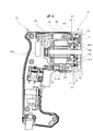
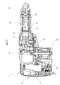
- a hammer drill 1 ⁇ / b> A is provided on a main body housing 10, a handle housing 20 provided on one end side of the main body housing 10, and provided on the other end side of the main body housing 10.
- Gear housing 30 and a casing 2 composed of the gear housing 30.
- an electric motor 40 which is a drive source of the tool bit 3 is housed in the main body housing 10. Therefore, in the following description, the main body housing 10 may be referred to as a “motor housing 10”.
- a part of the handle housing 20 partially covers the motor housing 10, and another part of the handle housing 20 forms a grip (handle 21) that is gripped by an operator.
- the gear housing 30 houses gears and the like that constitute a power transmission system that transmits the driving force output from the electric motor 40 to the tool bit 3.
- FIG. 2 is referred to again.
- the motor housing 10 has a small diameter portion 10a having a relatively small diameter and a large diameter portion 10b having a relatively large diameter, and has a substantially cylindrical appearance as a whole.
- An inner cover 12 is attached to the opening 11 of the motor housing 10, and the motor housing 10 and the gear housing 30 abut each other with the flange 12 a of the inner cover 12 interposed therebetween.
- the handle housing 20 is provided at one axial end of the motor housing 10, and the gear housing 30 is provided at the other axial end of the motor housing 10.
- the motor housing 10 is sandwiched between the handle housing 20 and the gear housing 30.
- the side where the handle housing 20 is provided is referred to as “rear”, and the side where the gear housing 30 is provided is “front” with respect to the motor housing 10. That is, the handle housing 20, the motor housing 10, and the gear housing 30 are arranged in this order from rear to front.
- the electric motor 40 accommodated in the motor housing 10 includes a stator (stator 41), a rotor (rotor 42) rotatably provided inside the stator 41, and a rotor 42. And an output shaft (output shaft 43) fixed to the brushless motor. Most of the electric motor 40 is housed in the small diameter portion 10 a of the motor housing 10.
- An output shaft 43 of the electric motor 40 extends through the rotor 42 in the front-rear direction.
- the front-back direction is a direction parallel to the direction of the output shaft 43 (the left-right direction in FIG. 3).
- the front-back direction is also a direction along the longitudinal direction of the tool bit 3.
- the rear end of the output shaft 43 is rotatably supported by a bearing 44 provided at the bottom of the motor housing 10, and the front end of the output shaft 43 is rotated by a bearing 45 held by the inner cover 12. Supported as possible.
- a first circuit board 46, a second circuit board 47, and a cooling fan 48 are housed in the motor housing 10 in addition to the electric motor 40.
- the first circuit board 46, the second circuit board 47, and the cooling fan 48 are accommodated in the large diameter portion 10b of the motor housing 10.
- the distal end side of the output shaft 43 of the electric motor 40 passes through the first circuit board 46, the second circuit board 47, and the cooling fan 48 in this order to reach the bearing 45. Further, the distal end side of the output shaft 43 penetrates the inner cover 12 and enters the gear housing 30. A first gear 49 is provided at the tip of the output shaft 43 that has entered the gear housing 30.
- a drive circuit including a switching element is mounted on a first circuit board 46 housed in the motor housing 10, and a control circuit including a hall element is mounted on a second circuit board 47.
- the cooling fan 48 is fixed so as not to rotate relative to the output shaft 43, and when the output shaft 43 rotates, the cooling fan 48 also rotates.
- the handle housing 20 and the motor housing 10 are provided with a plurality of wind windows.
- the cooling fan 48 rotates, air flows into the handle housing 20 through an air window provided in the handle housing 20.
- the air that has flowed into the handle housing 20 flows into the motor housing 10 through an air window provided in the motor housing 10.
- the air flowing into the motor housing 10 passes through the electric motor 40, the first circuit board 46, and the second circuit board 47 in this order.
- the handle housing 20 also houses a third circuit board 26 (FIG. 4) on which a rectifier circuit connected to the electrolytic capacitor 26a is mounted, and the electrolytic capacitor 26a and the third circuit board 26 are also cooled by the cooling air. Cooled.
- the handle housing 20 includes two housing members (a first housing member 22 and a second housing member 23) opposed to each other with a part (small diameter portion 10a) of the motor housing 10 interposed therebetween.
- a direction parallel to the facing direction of the first housing member 22 and the second housing member 23 is defined as a left-right direction.
- a direction that intersects both the left-right direction and the front-back direction is defined as the up-down direction. That is, the illustrated handle 21 extends in the up-down direction.
- a trigger lever 24 is provided on the handle 21, and a trigger switch 25 is provided behind the trigger lever 24 (inside the handle housing 20).
- the trigger switch 25 When the trigger switch 25 is turned on in response to the operation of the trigger lever 24, electric power is supplied to the electric motor 40, and the rotor 42 and the output shaft 43 rotate.
- the trigger switch 25 when the trigger switch 25 is turned off in response to the operation of the trigger lever 24, the power supply to the electric motor 40 is stopped, and the rotation of the rotor 42 and the output shaft 43 is stopped.
- the gear housing 30 has a substantially cylindrical shape.
- an intermediate shaft 50 is housed in the gear housing 30 in parallel with the output shaft 43.
- the rear end of the intermediate shaft 50 is rotatably supported by a bearing 51, and the front end is rotatably supported by a bearing 52.
- a second gear 53 that always meshes with a first gear 49 provided on the output shaft 43 is provided.
- the conversion mechanism 54 includes an inner ring, an outer ring, a rolling element, and a connecting rod.
- the inner race is attached to the intermediate shaft 50
- the outer race is provided around the inner race
- the rolling elements are interposed between the inner race and the outer race
- the connecting rod is integrally formed with the outer race.
- On the outer peripheral surface of the inner race and on the inner peripheral surface of the outer race arc-shaped grooves that cross each other are formed.
- the rolling element is interposed between the inner ring and the outer ring with a part fitted in a groove formed in the inner ring and another part fitted in a groove formed in the outer ring. In other words, the inner ring and the outer ring are connected via a rolling element so as to be relatively rotatable.
- a clutch 55 that can be switched between an engaged state in which power is transmitted from the intermediate shaft 50 to the conversion mechanism 54 and a released state in which power is not transmitted from the intermediate shaft 50 to the conversion mechanism 54 is provided. Is provided.
- the clutch 55 cannot rotate relative to the intermediate shaft 50, and can move forward and backward along the intermediate shaft 50.
- the clutch 55 retreats to a predetermined position (when it comes close to the inner wheel)
- the intermediate shaft 50 and the inner wheel are connected via the clutch 55, and power is transmitted from the intermediate shaft 50 to the inner wheel.
- the clutch 55 moves forward to a predetermined position (when it separates from the inner wheel)
- the connection between the intermediate shaft 50 and the inner wheel is released, and power transmission from the intermediate shaft 50 to the inner wheel is cut off.
- Such switching of the clutch 55 is realized according to a mode switching operation by an operator.
- the intermediate shaft 50 rotates while the clutch 55 is in the engaged state
- the inner ring rotates.
- the outer ring rolls along the surface of the inner ring, and accordingly, the connecting rod swings back and forth.
- a third gear 56 is provided on the intermediate shaft 50 and in front of the clutch 55.
- the third gear 56 is movable back and forth along the intermediate shaft 50.
- the third gear 56 and the intermediate shaft 50 are spline-fitted.
- the spline fitting between the third gear 56 and the intermediate shaft 50 is released. That is, the third gear 56 can move back and forth along the intermediate shaft 50, and can be in a connected state in which the third gear 56 rotates integrally with the intermediate shaft 50, or in a non-connected state in which the third gear 56 does not rotate even when the intermediate shaft 50 rotates.
- Switch The switching of the third gear 56 is realized according to a mode switching operation by an operator.
- a cylinder 60 is accommodated in the gear housing 30 in parallel with the output shaft 43 and the intermediate shaft 50.
- the cylinder 60 houses a piston 61, a striker 62, and a meson 63.
- the piston 61, the striker 62, and the meson 63 are arranged in a line in this order from the rear to the front, and an air chamber 64 is provided between the piston 61 and the striker 62.
- a retainer sleeve 65 is provided in front of the cylinder 60 as a holding unit.
- the rear end of the retainer sleeve 65 is connected to the front end of the cylinder 60, and the cylinder 60 and the retainer sleeve 65 are fixed so as not to rotate relative to each other.
- the root of the tool bit 3 is inserted into the retainer sleeve 65.
- the retainer sleeve 65 holds the root of the inserted tip tool so as to be able to linearly move within a predetermined range.
- the connecting rod of the conversion mechanism 54 is rotatably connected to the back surface of the piston 61.
- the piston 61 reciprocates back and forth within the cylinder 60.
- a fourth gear 66 is provided on the outer peripheral surface of the cylinder 60 to selectively mesh with the third gear 56 provided on the intermediate shaft 50. Specifically, when the third gear 56 is switched to the connected state by the mode switching operation by the operator, the third gear 56 and the fourth gear 66 mesh with each other. Then, the rotational force of the intermediate shaft 50 is transmitted to the cylinder 60 via the third gear 56 and the fourth gear 66, and the cylinder 60 rotates.
- the clutch 55 is released and the third gear 56 is connected.
- the intermediate shaft 50 rotates in this state, the inner ring of the conversion mechanism 54 does not rotate, while the cylinder 60 rotates. As a result, only the rotational force is applied to the tip tool 3 held by the retainer sleeve 65.
- the clutch 55 is engaged and the third gear 56 is disengaged.
- the intermediate shaft 50 rotates in this state, the inner ring rotates, but the cylinder 60 does not rotate. Therefore, the piston 61 reciprocates in the stationary cylinder 60, and the pressure in the air chamber 64 fluctuates. Then, the striker 62 is driven by the pressure fluctuation of the air chamber 64, the striker 62 strikes the meson 63, and the meson 63 strikes the tip tool 3. As a result, only the impact force is applied to the tip tool 3 held by the retainer sleeve 65.
- the motor housing 10 and the handle housing 20 shown in FIG. 1 are connected to be relatively movable in the direction of the output shaft 43 (FIG. 3).
- the handle housing 20 can move forward and backward with respect to the motor housing 10.
- a gap D1 of about 3.0 mm is provided between the motor housing 10 and the handle housing 20, and the handle housing 20 is separated from the motor housing 10 within the range of the gap D1. You can go back and forth.
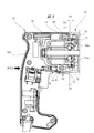
- a coil spring 70 as a first elastic body and rubbers 71 and 72 as a second elastic body are interposed between the motor housing 10 and the handle housing 20.
- the rubber 71 and the rubber 72 are arranged at different positions in the vertical direction. Specifically, the rubber 71 is arranged on the upper part of the motor housing 10 and corresponds to an upper elastic body.
- the rubber 72 is disposed below the motor housing 10 and corresponds to a lower elastic body. Therefore, in the following description, the rubber 71 may be referred to as “upper rubber 71” and the rubber 72 may be referred to as “lower rubber 72”. Note that the coil spring 70 is disposed at substantially the same height as the lower rubber 72.
- the coil spring 70 is arranged between a rib in the handle housing 20 and the bottom of the motor housing 10. One end (tip) of the coil spring 70 contacts the bottom of the motor housing 10, and the other end (rear end) of the coil spring 70 contacts the rib of the handle housing 20. That is, one end (front end) of the coil spring 70 is always in contact with the motor housing 10, and the other end (rear end) of the coil spring 70 is always in contact with the handle housing 20. Therefore, the coil spring 70 expands and contracts as the handle housing 20 advances and retreats with respect to the motor housing 10. The coil spring 70 is preloaded. In other words, the coil spring 70 is arranged between the motor housing 10 and the handle housing 20 in a compressed state.
- a force is applied to the motor housing 10 and the handle housing 20 in a direction to separate them from each other. That is, the handle housing 20 is urged rearward, and the motor housing 10 is urged forward. Therefore, when no pressing force is applied to the handle housing 20 in a direction (forward) for bringing the handle housing 20 close to the motor housing 10, the gap D1 is maximized. In other words, when no pressing force is applied to the handle housing 20, the handle housing 20 is most retracted with respect to the motor housing 10. In the following description, a state in which no pressing force is applied to the handle housing 20 and thus the gap D1 is maximum may be referred to as a "no-load state".
- the entire length of the coil spring 70 in a no-load state may be referred to as a “set length”.
- the “set length” of the coil spring 70 is shorter than the “natural length” of the coil spring 70.
- the coil spring 70 is given a preload of 2.5 kgf.
- the coil spring 70 is compressed by 1.0 mm with respect to the natural length. That is, the set length of the coil spring 70 is the natural length -1.0 mm.
- one ends (tips) of the upper rubber 71 and the lower rubber 72 are always in contact with the motor housing 10. Specifically, a part (tip side) of the upper rubber 71 and the lower rubber 72 is fitted in the holding hole 13 provided in the motor housing 10, respectively. On the other hand, when there is no load, nothing is in contact with the rear ends of the upper rubber 71 and the lower rubber 72.
- the illustrated first housing member 22 and second housing member 23 include two connecting members (upper connecting member 80 and lower connecting member 80) that connect the first housing member 22 and the second housing member 23 across the motor housing 10. They are fixed to each other via a side connection member 81) and are integrated.
- the upper connecting member 80 and the lower connecting member 81 are formed in columns extending in the left-right direction orthogonal to the advancing / retreating direction (front-back direction) of the handle housing 20, and flat portions 80a, 81a are provided on a part of the outer surface. Have been.
- the upper connecting member 80 is inserted into the upper guide portion 14 as a tunnel-shaped hole provided in the upper part of the motor housing 10, one end of which is fixed to the first housing member 22, and the other end of which is the second It is fixed to the housing member 23.
- the lower connecting member 81 is inserted into the lower guide portion 15 (FIG. 4) as another tunnel-shaped hole provided in the lower portion of the motor housing 10, and one end thereof is connected to the first housing member 22. The other end is fixed to the second housing member 23. More specifically, one end of the upper connecting member 80 is fitted into a concave portion provided inside the first housing member 22, and the other end of the upper connecting member 80 is It fits into a recess provided inside housing member 23. Further, an intermediate portion of the upper connecting member 80 including the flat portion 80a penetrates the insertion hole 14a (FIG. 4) of the upper guide portion 14.
- one end of the lower connecting member 81 is fitted into a concave portion provided on the inner surface of the first housing member 22, and the other end of the lower connecting member 81 is connected to the second housing member 22. It is fitted in a concave portion provided on the inner surface of the member 23. Further, an intermediate portion of the lower connecting member 81 including the flat portion 81a penetrates the insertion hole 15a (FIG. 4) of the lower guide portion 15.
- the first housing member 22 penetrates the first housing member 22 and is fixed to one end of the upper connection member 80 and the lower connection member 81 by a fixing tool (screw). It is fixed to 81.
- the second housing member 23 penetrates through the second housing member 23, and is fixed to the other end of the upper connection member 80 and the lower connection member 81 by a fixing tool (screw). It is fixed to 81. That is, the first housing member 22 and the second housing member 23 are integrated by being fixed to the common connecting members 80 and 81.
- the upper connection member 80 and the lower connection member 81 in the present embodiment are separate from the first housing member 22 and the second housing member 23.
- the upper connecting member 80 and the lower connecting member 81 are separate from the handle housing 20.
- the first housing member 22 and the second housing member 23 are fixed to each other by the fixing structure as described above. That is, the upper connecting member 80 and the lower connecting member 81 form the handle housing 20 together with the first housing member 22 and the second housing member 23, and are a part of the handle housing 20.
- FIG. 4 is referred to again.
- the flat portion 80a of the upper connecting member 80 forms a pressing surface facing the rear end surface of the upper rubber 71 in the advancing and retreating direction of the handle housing 20.
- the flat portion 81 a of the lower connecting member 81 forms a pressing surface that faces the rear end surface of the lower rubber 72 in the advancing and retreating direction of the handle housing 20.
- the upper rubber 71 faces the flat portion 80a of the upper connecting member 80 inside the insertion hole 14a of the upper guide portion 14.
- the lower rubber 72 faces the flat portion 81 a of the lower connecting member 81 inside the insertion hole 15 a of the lower guide portion 15. That is, the upper rubber 71 and the lower rubber 72 are arranged between the connecting members (the upper connecting member 80 and the lower connecting member 81) and the motor housing 10 in the advancing / retreating direction (front-back direction) of the handle housing 20. .
- a gap D2 of about 1.5 mm is provided between the flat portion 80a of the upper connecting member 80 and the upper rubber 71 and between the flat portion 81a of the lower connecting member 81 and the lower rubber 72.
- the upper connecting member 80 is not in contact with the upper rubber 71, and the lower connecting member 81 is not in contact with the lower rubber 72.
- the handle housing 20 is urged rearward by the coil spring 70.
- the distal end of the coil spring 70 in a compressed state is always in contact with the motor housing 10, and the rear end is always in contact with the handle housing 20.
- the coil spring 70 is further compressed accordingly.
- the overall length of the coil spring 70 is reduced by the same length as the forward movement distance of the handle housing 20.
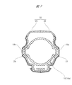
- the inner dimensions of the insertion hole 14a and the insertion hole 15a are smaller (smaller) in the vertical direction than in the front-rear direction. Therefore, the movement of the upper connecting member 80 and the lower connecting member 81 in the vertical direction is restricted by the insertion holes 14a and the insertion holes 15a, and exclusively moves in the front-back direction.
- the width in the up-down direction is the width in the front-rear direction (forward / backward direction) and the direction orthogonal to the left-right direction (the width in the up-down direction on the paper of FIG. 4).
- the gap D1 shown in FIG. 4 is set to about 3.0 mm, and the gap D2 is set to about 1.5 mm. Therefore, as shown in FIG. 5, when the handle housing 20 moves forward (approaches the motor housing 10) until the gap D1 decreases to about 1.5 mm, the upper connecting member 80 contacts the upper rubber 71, and The side connecting member 81 contacts the lower rubber 72. Thereafter, as shown in FIG. 6, when the handle housing 20 further advances (closer to the motor housing 10), the upper rubber 71 is compressed by the upper connecting member 80, and the lower rubber 72 is compressed by the lower connecting member 81. Is compressed.
- the upper connecting member 80 contacts the upper rubber 71 and the lower connecting member 81 contacts the lower rubber 72. Abut Thereafter, when the coil spring 70 is further compressed, and the total length of the coil spring 70 is less than the predetermined length, the upper rubber 71 is compressed by the upper connecting member 80 and the lower rubber 72 is compressed by the lower connecting member 81.
- the magnitude of the pressing force required to compress the coil spring 70 until the entire length reaches a predetermined length (set length-1.5 mm) can be set in advance based on the spring constant of the coil spring 70.
- the spring constant of the coil spring 70 in the present embodiment is 2.5 kgf / mm, and the preload is 2.5 kgf.
- the compression of the coil spring 70 starts.
- the upper connecting member 80 comes into contact with the upper rubber 71
- the lower connecting member 81 comes into contact with the lower rubber 72.
- the upper connecting member 80 compresses the upper rubber 71
- the lower connecting member 81 compresses the lower rubber 72.
- only the coil spring 70 is compressed until the pressing force applied to the handle housing 20 exceeds 2.5 kgf and reaches 6.5 kgf, and after the pressing force exceeds 6.5 kgf, the coil spring 70 is applied.
- the upper rubber 71 and the lower rubber 72 are compressed.
- the vibration isolating structure employed in the hammer drill 1A according to the present embodiment when no pressing force is applied to the handle housing 20, or when the pressing force applied to the handle housing 20 has a predetermined magnitude.
- the first elastic body (coil spring 70) absorbs or attenuates the vibration transmitted from the motor housing 10 to the handle housing 20.
- the pressing force applied to the handle housing 20 exceeds a predetermined magnitude, the first elastic body (coil spring 70) and the second elastic body (upper rubber 71, lower rubber 72) are separated from the motor housing 10.
- the vibration transmitted to the handle housing 20 is absorbed or attenuated. Therefore, the anti-vibration structure employed in the hammer drill 1A according to the present embodiment exhibits a sufficient anti-vibration effect even if the presence or absence of the force applied to the handle 21 or the magnitude changes.
- the hammer drill 1A is provided with a regulating means that functions at least in a no-load state and that suppresses or prevents the occurrence of play between the motor housing 10 and the handle housing 20.
- a regulating means that functions at least in a no-load state and that suppresses or prevents the occurrence of play between the motor housing 10 and the handle housing 20.
- the restricting means included in the hammer drill 1A includes a plurality of restricting surfaces provided on the motor housing 10 and the handle housing 20.
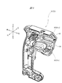
- the handle housing 20 is provided with a plurality of handle-side regulating surfaces 90.
- the motor housing 10 is provided with a plurality of body-side regulating surfaces 100.
- the handle side regulating surface 90 provided on the handle housing 20 will be described in detail, and then the main body side regulating surface 100 provided on the motor housing 10 will be described in detail.
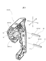
- the handle-side regulating surface 90 is formed by a first handle-side regulating surface formed by a part of a surface of a rib protruding inside the handle housing 20 and a part of an outer surface of the connecting members 80 and 81. And a second handle-side regulating surface. As shown in FIG. 8, two first handle-side regulating surfaces 91a and 91b are provided inside the first housing member 22. Further, as shown in FIG. 9, two first handle-side regulating surfaces 91c and 91d are provided inside the second housing member 23.
- first handle-side regulating surfaces 91a, 91b provided on the first housing member 22 are referred to as “handle right-side regulating surfaces 91a, 91b", and the first handle provided on the second housing member 23.
- the side regulating surfaces 91c and 91d may be referred to as “handle left regulating surfaces 91c and 91d”.
- the right handle regulating surface 91a and the left handle regulating surface 91c are located at the same height, and the right handle regulating surface 91b and the left handle regulating surface 91d are located at the same height.
- the handle right regulating surface 91a and the handle right regulating surface 91b are formed on a part of the inner surface of the first housing member 22 that covers the main housing 10.
- the handle left side regulating surface 91c and the handle left side regulating surface 91d are formed on a part of the inner surface of the second housing member 23 that covers the main body housing 10.
- the first handle-side regulating surfaces 91a to 91d are inclined in the same direction. Specifically, the first handle-side regulating surfaces 91a to 91d are inclined in the front-rear direction and the left-right direction, but are parallel to the up-down direction.
- a plurality of handle side rails are provided on a part of the inner surface of the first housing member 22 and the second housing member 23 that covers the main body housing 10.
- an upper rail portion 93 and a lower rail portion 94 protruding leftward are formed on a part of the inner surface of the first housing member 22 that covers the main body housing 10.
- An upper rail portion 95 and a lower rail portion 96 projecting rightward are formed on a part of the inner surface of the second housing member 23 that covers the main housing 10.
- the upper rail portions 93 and 95 and the lower rail portions 94 and 96 are arranged at positions corresponding to a plurality of main body side rail portions provided in a main body housing described later, and are combined so as to slide with each other.
- the upper handle 80 has a second handle-side regulating surface 92 formed by another part different from a part of the outer surface forming the pressing surface (flat portion 80a).
- a second handle side regulating surface 92 is formed by another portion different from a portion of the outer surface forming the pressing surface (flat portion 81a).
- the second handle-side regulating surface 92 provided on the upper connecting member 80 is referred to as “the handle upper regulating surface 92”
- the second handle-side regulating surface 92 provided on the lower connecting member 81 is referred to as “the handle upper regulating surface 92”. It may be referred to as a "handle lower regulation surface 92".
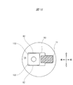
- the handle upper regulation surface 92 and the handle lower regulation surface 92 have an upward regulation surface 92a that is inclined upward from the rear to the front, and faces upward from the rear. And a downward regulating surface 92b that is inclined downward.
- the upward regulating surface 92a (FIG. 15 (a)) provided on the upper connecting member 80 and the upward regulating surface 92a (FIG. 15 (b)) provided on the lower connecting member 81 are in the same direction. It is inclined. Specifically, each upward regulation surface 92a is inclined with respect to the front-rear direction and the up-down direction, while being parallel to the left-right direction.
- the downward regulating surface 92b (FIG.
- each downward regulation surface 92b is inclined with respect to the front-back direction and the up-down direction, while being parallel to the left-right direction.
- the handle housing 20 is provided with the plurality of handle-side regulating surfaces 90.
- the plurality of handle-side regulating surfaces 90 include first handle-side regulating surfaces (handle-right regulating surfaces) 91 a and 91 b provided on the first housing member 22 and second handle member-side regulating surfaces 91 a and 91 b provided on the second housing member 23.
- the first handle-side regulating surface (left-hand handle regulating surface) 91c, 91d and the second handle-side regulating surface 92 provided on each of the connecting members 80, 81 are included.
- each of the second handle-side regulating surfaces 92 includes an upward regulating surface 92a and a downward regulating surface 92b.
- the first handle-side regulating surfaces 91a to 91d provided on the first housing member 22 or the second housing member 23 are inclined in the front-rear direction and the left-right direction, and are parallel to the up-down direction.
- the second handle-side regulating surface 92 provided on each of the connecting members 80 and 81 is inclined with respect to the front-rear direction and the vertical direction, and is parallel to the left-right direction.
- the body-side regulating surface 100 includes a first body-side regulating surface formed by a part of a surface of a rib protruding outside the motor housing 10, and an upper guide portion 14 and a lower guide portion 15 of the motor housing 10. And a second main body side regulating surface formed by a part of the inner surface of the second main body.
- two first body-side regulating surfaces 101a and 101b are provided on the right side surface of the motor housing 10 covered by the first housing member 22 (FIG. 8).
- two first body-side regulating surfaces 101c and 101d are provided on the left side surface of the motor housing 10 covered with the second housing member 23 (FIG. 9).
- the first main body side regulating surfaces 101a and 101b provided on the right side surface of the motor housing 10 will be referred to as “main body right side regulating surfaces 101a and 101b”, and the first main body side regulating surfaces 101a and 101b will be described.
- the one main body side regulating surfaces 101c and 101d may be referred to as “main body left side regulating surfaces 101c and 101d”.
- the right main body regulating surface 101a and the left main body regulating surface 101c are located at the same height, and the right main body regulating surface 101b and the left main body regulating surface 101d are located at the same height. Further, the main body right regulating surface 101a is located at the same height as the handle right regulating surface 91a (FIG. 8), and faces the handle right regulating surface 91a. Similarly, the main body left regulating surface 101c (FIG. 11) is located at the same height as the handle left regulating surface 91c (FIG. 9), and faces the handle left regulating surface 91c. The body right regulating surface 101b (FIG. 10) is located at the same height as the handle right regulating surface 91b (FIG. 8), and faces the handle right regulating surface 91b. The main body left regulating surface 101d (FIG. 11) is located at the same height as the handle left regulating surface 91d (FIG. 9), and faces the handle left regulating surface 91d.
- the motor housing 10 is provided with a plurality of main body side rails.
- the motor housing 10 includes an upper right rail 103 and a lower right rail 104 projecting rightward, and an upper left rail 105 and a lower left rail 106 projecting leftward. Is provided.
- the main body side rail portion and the handle side rail portion are arranged at corresponding positions, and are combined so as to slide with each other.
- the upper right rail 103 is the upper rail 93
- the lower right rail 104 is the lower rail 94
- the upper left rail 105 is the upper rail 95
- the lower left rail 106 is the lower rail.
- the side rails 96 are arranged at corresponding positions, and are slidably combined with each other.
- the handle housing 20 can be smoothly advanced and retracted with respect to the main body housing (motor housing) 10 and the regulating surface can be formed.
- the rail portion can be formed by a single mold, so that it can be manufactured at low cost.
- the regulating surface and the plurality of handle-side rails on the inner surface of the handle housing 20 that covers the main body housing 10, compared to a configuration in which the handle housing 20 is separately provided with the regulating surface and the plurality of handle-side rails, Enlargement of the handle housing 20 can be suppressed and the strength can be secured.
- the first main body side regulating surfaces 101a to 101d are inclined in the same direction. Specifically, the first main body side regulating surfaces 101a to 101d are inclined with respect to the front-rear direction and the left-right direction, while being parallel to the up-down direction.
- the inclination of the first body-side regulating surfaces 101a to 101d is the same as the inclination of the first handle-side regulating surfaces 91a to 91d shown in FIGS. That is, the first main body side regulating surfaces 101a to 101d are inclined surfaces along the first handle side regulating surfaces 91a to 91d.
- the first handle side regulating surfaces 91a to 91d are inclined surfaces along the first main body side regulating surfaces 101a to 101d.
- a second body-side regulating surface 102 is formed by a flat part of the inner surface.
- the second body-side regulating surface 102 is also formed inside the lower guide portion 15 by a flat part of the inner surface.
- the second main body side regulating surface 102 provided on the upper guide portion 14 is referred to as “main body upper side regulating surface 102”
- the second main body side regulating surface 102 provided on the lower guide portion 15 is referred to as “second main body side regulating surface 102”. It may be referred to as “main body lower regulation surface 102”.
- the upper regulating surface 102 provided on the upper guide portion 14 and the lower guide portion 15 has an upward regulating surface inclined upward from the rear toward the front. 102a and a downward regulating surface 102b inclined downward from the rear to the front.
- the upward regulating surface 102a (FIG. 15 (a)) provided on the upper guide portion 14 and the upward regulating surface 102a (FIG. 15 (b)) provided on the lower guide portion 15 are inclined in the same direction. are doing. Specifically, each upward regulation surface 102a is inclined with respect to the front-rear direction and the up-down direction, while being parallel to the left-right direction.
- the downward regulating surface 102b (FIG.
- each downward regulation surface 102b is inclined with respect to the front-rear direction and the up-down direction, while being parallel to the left-right direction.
- the inclination of the main body upper regulating surface 102 corresponds to the handle upper regulating surface 92 (the upward regulating surface) provided on the upper connecting member 80. 92a) and the inclination of the downward regulating surface 92b).
- the inclination of the main body lower regulating surface 102 corresponds to the handle lower regulating surface 92 (provided on the lower connecting member 81). This corresponds to the inclination of the upward regulating surface 92a and the downward regulating surface 92b).
- the upward regulating surface 102a and the downward regulating surface 102b of the upper guide portion 14 and the upward regulating surface 92a and the downward regulating surface 92b of the upper connecting member 80 face each other.
- the upward regulation surface 102a and the downward regulation surface 102b of the lower guide portion 15 and the upward regulation surface 92a and the downward regulation surface 92b of the lower connecting member 81 face each other. That is, the second body-side regulating surface 102 is a plane that is inclined along the second handle-side regulating surface 92.
- the second handle-side regulating surface 92 is a plane that is inclined along the second body-side regulating surface 102.
- the motor housing 10 is provided with the plurality of main body side regulating surfaces 100.
- the plurality of main body side regulating surfaces 100 are provided on first main body side regulating surfaces (main body right regulating surfaces) 101 a and 101 b provided on the right side surface of the motor housing 10 and on the left side surface of the motor housing 10.
- the first main body side regulating surfaces (main body left side regulating surfaces) 101c and 101d, and the second main body side regulating surfaces 102 provided on the upper guide portion 14 and the lower guide portion 15, respectively.
- each of the second main body side regulating surfaces 102 includes an upward regulating surface 102a and a downward regulating surface 102b.
- the first body-side regulating surfaces 101a to 101d are inclined in the front-rear direction and the left-right direction, and are parallel to the up-down direction.
- the second main body side regulating surface 102 is inclined with respect to the front-rear direction and the up-down direction, and is parallel to the left-right direction.
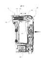
- FIGS. 12 and 13 are views showing the positional relationship between the handle side regulating surface 90 (FIGS. 8 and 9) and the main body side regulating surface 100 (FIGS. 10 and 11) in a no-load state. As described above, in the no-load state, the handle housing 20 is most retracted with respect to the motor housing 10 by the bias of the coil spring 70 (FIG. 4).
- the handle upper regulating surface 92 when there is no load, the handle upper regulating surface 92 is in contact with the main body upper regulating surface 102. More specifically, the upward regulating surface 92a of the handle upper regulating surface 92 abuts on the upward regulating surface 102a of the main body upper regulating surface 102, and the downward regulating surface 92b of the handle upper regulating surface 92 faces the downward of the main body upper regulating surface 102. It is in contact with the regulating surface 102b.
- the handle lower regulating surface 92 when there is no load, the handle lower regulating surface 92 is in contact with the main body lower regulating surface 102. More specifically, the upward regulating surface 92a of the handle lower regulating surface 92 abuts on the upward regulating surface 102a of the main body lower regulating surface 102, and the downward regulating surface 92b of the handle lower regulating surface 92 is controlled by the lower body regulating surface. It is in contact with the downward regulating surface 102b of the surface 102.
- the plurality of handle-side regulating surfaces 90 abut on the corresponding body-side regulating surfaces 100, respectively.
- rattling of the handle housing 20 with respect to the motor housing 10 is prevented or suppressed.
- the first handle-side regulating surfaces 91a to 91d abut against the first main body-side regulating surfaces 101a to 101d, thereby preventing or suppressing rattling of the handle housing 20 in the left-right direction.
- the surface 92 abutting on the second main body side regulating surface 102 the backlash of the handle housing 20 in the vertical direction is prevented or suppressed.
- the backlash of the handle housing 20 in the front-rear direction is prevented or suppressed by the bias of the coil spring 70.
- FIGS. 14 and 15 are views showing the positional relationship between the handle-side regulating surface 90 (FIGS. 8 and 9) and the main-body-side regulating surface 100 (FIGS. 10 and 11) in a load state.
- the handle housing 20 In a loaded state, the handle housing 20 is advanced with respect to the motor housing 10 against the bias of the coil spring 70 (FIG. 4).
- the handle right regulation surface 91a that has been in contact with the main body right regulation surface 101a is separated from the main body right regulation surface 101a.
- the handle left-side regulating surface 91c which has been in contact with the main body left-side regulating surface 101c is separated from the main body left-side regulating surface 101c.
- the handle right-side regulating surface 91b that has been in contact with the main body right-side regulating surface 101b is separated from the main body right-side regulating surface 101b.
- the handle left-side regulating surface 91d that has been in contact with the main-body left-side regulating surface 101d is separated from the main-body left-side regulating surface 101d.
- the handle upper regulation surface 92 that has been in contact with the main body upper regulation surface 102 is separated from the main body upper regulation surface 102. More specifically, the upward regulating surface 92a of the handle upper regulating surface 92 is separated from the upward regulating surface 102a of the main body upper regulating surface 102, and the downward regulating surface 92b of the handle upper regulating surface 92 is oriented downward of the main body upper regulating surface 102. It separates from the regulation surface 102b.
- the handle lower-side regulating surface 92 that has been in contact with the main body upper-side regulating surface 102 is separated from the main body lower-side regulating surface 102. . More specifically, the upward regulating surface 92a of the handle lower regulating surface 92 is separated from the upward regulating surface 102a of the body lower regulating surface 102, and the downward regulating surface 92b of the handle lower regulating surface 92 is regulated to the body lower regulating surface. The surface 102 is separated from the downward regulating surface 102b.
- the handle-side regulating surface 90 is separated from the main-body-side regulating surface 100, and a clearance is generated between the handle housing 20 and the motor housing 10.
- the movement restriction of the handle housing 20 by the restriction means is released.
- smooth movement of the handle housing 20 with respect to the motor housing 10 is ensured, and the vibration transmitted from the motor housing 10 to the handle housing 20 is effectively reduced by the above-described vibration-proof structure.
- the elastic body constituting the above-mentioned vibration isolating structure is arranged at a predetermined position without using a special support member or a holding member.
- the coil spring 70 is disposed between the bottom of the motor housing 10 and the rib of the handle housing 20 and is compressed according to the movement of the handle housing 20.
- the motor housing 10 is a member necessary for holding the electric motor 40 that is a driving source, and is also a member necessary for an electric tool that does not have an anti-vibration structure.
- the ribs of the handle housing 20 are necessary to reinforce the handle housing 20, and are also provided on the handle housing of an electric tool that is not provided with an anti-vibration structure.
- the rubbers 71 and 72 are arranged between the motor housing 10 and the connecting members 80 and 81 that are a part of the handle housing 20.
- the connecting members 80 and 81 are necessary for fixing and integrating the first housing member 22 and the second housing member 23 with each other, and are also necessary for a power tool having no vibration isolating structure. is there.
- FIG. 16 shows a comparative example of the handle side regulating surface 90 and the main body side regulating surface 100.
- the handle-side regulating surface 90 and the main-body-side regulating surface 100 in the above embodiment are inclined surfaces that are inclined along the other party.
- the second handle side regulating surface 92 and the second main body side regulating surface 102 shown in FIG. 16 are planes parallel to the other party.
- the illustrated second handle-side regulating surface 92 and second main-body-side regulating surface 102 are planes that are parallel to the front-rear direction and the left-right direction, and are orthogonal to the vertical direction. is there.
- the spring constant of the coil spring 70 as the first elastic body can be changed as appropriate. By changing the spring constant of the coil spring 70, a region where only the coil spring 70 contributes to vibration proof (a range of the pressing force) and a region where both the coil spring 70 and the rubbers 71 and 71 contribute to vibration proof. (Range of pressing force) can be set arbitrarily.
- the connecting member that connects the first housing member and the second housing member may be integral with the first housing member or the second housing member.
- the first housing member 22 and the second housing member 23 are fixed. Can also be integrated.
- the connecting member does not have to penetrate the main body housing.
- the illustrated upper connecting member 80 may pass (cross) over the motor housing 10 and straddle the first housing member 22 and the second housing member 23.
- the lower connecting member 81 may pass (cross) below the motor housing 10 and straddle the first housing member 22 and the second housing member 23.
- the power tool according to the present embodiment is a hammer having substantially the same structure as the hammer drill 1A according to the first embodiment. Therefore, the same or substantially the same components as those already described are denoted by the same reference numerals, and duplicate description will be omitted as appropriate.
- the hammer 1B shown in FIG. 17 includes a casing 2 including a motor housing 10, a handle housing 20, and a gear housing 30.
- the handle housing 20 has a generally U-shaped appearance in a side view, an upper portion thereof is connected to an upper portion of the motor housing 10, a lower portion thereof is connected to a lower portion of the motor housing 10, and an intermediate portion between the upper portion and the lower portion.
- a handle 21 is formed.
- the lower portion of the handle housing 20 is rotatably connected to the motor housing 10 via a hinge 190. Accordingly, the handle housing 20 rotates in a direction approaching the motor housing 10 (leftward in the drawing) when the pressing force is applied, and separates from the motor housing 10 when the application of the pressing force is released. It rotates in the direction (right direction in the figure). That is, the handle housing 20 can move forward and backward with respect to the motor housing 10.
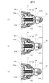
- FIG. 19A shows a relative positional relationship between the motor housing 10 and the handle housing 20 when no pressing force is applied to the handle housing 20. That is, it shows the relative positional relationship between the motor housing 10 and the handle housing 20 when there is no load.
- FIG. 19B shows a relative positional relationship between the motor housing 10 and the handle housing 20 when a predetermined pressing force is applied to the handle housing 20.
- FIG. 19C illustrates a relative positional relationship between the motor housing 10 and the handle housing 20 when a pressing force exceeding a predetermined magnitude is applied to the handle housing 20.
- a coil spring 191 as a first elastic body and a coil spring 192 as a second elastic body are interposed between the upper part of the motor housing 10 and the upper part of the handle housing 20. ing. Further, the coil spring 192 as the second elastic body is inserted inside the coil spring 191 as the first elastic body. In other words, the coil spring 191 as the first elastic body is covered outside the coil spring 192 as the second elastic body. Therefore, in the following description, the coil spring 191 as the first elastic body may be referred to as “outer coil spring 191”, and the coil spring 192 as the second elastic body may be referred to as “inner coil spring 192”.
- one end (tip) of the outer coil spring 191 on the motor housing 10 side protrudes from one end (tip) of the inner coil spring 192 on the motor housing 10 side.
- one end (rear end) of the inner coil spring 192 on the handle housing 20 side protrudes from one end (rear end) of the outer coil spring 191 on the handle housing 20 side.
- a main body side holding member 193 is provided on an upper portion of the motor housing 10.
- a handle-side holding member 194 extending toward the motor housing 10 (main-body-side holding member 193) is provided above the handle housing 20.
- the handle side holding member 194 is fixed to the handle housing 20 and moves integrally with the handle housing 20 with respect to the motor housing 10.
- the outer coil spring 191 and the inner coil spring 192 are arranged between the main body side holding member 193 and the handle side holding member 194.
- the handle-side holding member 194 is formed with a cylindrical or groove-shaped housing portion 195, and the housing portion 195 houses most of the outer coil spring 191 and the inner coil spring 192 in the longitudinal direction. I have.
- An outer contact surface 195a facing the rear end of the outer coil spring 191 and an inner contact surface 195b facing the rear end of the inner coil spring 192 are formed on the bottom of the housing portion 195.
- the outer contact surface 195a is formed one step higher than the inner contact surface 195b, and surrounds the inner contact surface 195b.
- the bottom of the housing portion 195 has a stepped shape according to the difference in height between the rear end of the outer coil spring 191 and the rear end of the inner coil spring 192.
- the main body side holding member 193 is formed with an outer contact surface 193a facing the tip of the outer coil spring 191 and an inner contact surface 193b facing the tip of the inner coil spring 192.
- the outer contact surface 193a is formed one step lower than the inner contact surface 193b, and surrounds the inner contact surface 193b. That is, the main body side holding member 193 has a stepped shape according to the difference in height between the tip of the outer coil spring 191 and the tip of the inner coil spring 192.
- the tip of the outer coil spring 191 in a no-load state, is in contact with the outer contact surface 193a of the main body side holding member 193, and the rear end of the outer coil spring 191 is on the handle side. It is in contact with the outer contact surface 195a of the holding member 194.
- the tip of the inner coil spring 192 is in contact with the inner contact surface 193b of the main body side holding member 193, but the rear end of the inner coil spring 192 is in contact with the inner contact surface 195b of the handle side holding member 194.
- the outer coil spring 191 is provided with a preload.
- the outer coil spring 191 is compressed accordingly. . That is, the overall length of the outer coil spring 191 decreases in accordance with the distance that the handle housing 20 moves forward.
- the inner contact surface 195b of the handle side holding member 194 contacts the rear end of the inner coil spring 192.
- the inner contact surface 195b of the handle side holding member 194 contacts the rear end of the inner coil spring 192.
- the inner contact surface 195b of the handle side holding member 194 does not contact the rear end of the inner coil spring 192, and Only 191 is compressed. That is, only the outer coil spring 191 contributes to the vibration isolation until the pressing force applied to the handle housing 20 reaches a predetermined value.
- the inner coil spring 192 is also compressed in addition to the outer coil spring 191. That is, when the pressing force applied to the handle housing 20 exceeds a predetermined magnitude, both the outer coil spring 191 and the inner coil spring 192 are compressed, and both the outer coil spring 191 and the inner coil spring 192 contribute to vibration isolation. I do.
- the magnitude of the pressing force required to compress the outer coil spring 191 until the entire length reaches the predetermined length can be set in advance based on the spring constant of the outer coil spring 191. Therefore, by changing the spring constant of the outer coil spring 191, the region (the range of the pressing force) where only the outer coil spring 191 contributes to the vibration proof, and both the outer coil spring 191 and the inner coil spring 192 for the vibration proof.
- the region (the range of the pressing force) that contributes can be set arbitrarily.
- the vibration isolation structure employed in the hammer 1B according to the present embodiment when the pressing force is not applied to the handle housing 20, or when the pressing force applied to the handle housing 20 has a predetermined magnitude. When it is lower, only the first elastic body (outer coil spring 191) absorbs or attenuates the vibration transmitted from the motor housing 10 to the handle housing 20. On the other hand, when the pressing force applied to the handle housing 20 exceeds a predetermined magnitude, the first elastic body (outer coil spring 191) and the second elastic body (inner coil spring 192) are transmitted from the motor housing 10 to the handle housing 20. Absorb or attenuate vibrations. Therefore, the anti-vibration structure employed in the hammer 1B according to the present embodiment exerts a sufficient anti-vibration effect even if the presence or absence of the force applied to the handle 21 or the magnitude changes.
- the power tool according to the present embodiment is a hammer drill having substantially the same structure as the hammer drill 1A according to the first embodiment. Therefore, the same or substantially the same components as those already described are denoted by the same reference numerals, and duplicate description will be omitted as appropriate.
- a hammer drill 1C shown in FIG. 20 includes a casing 2 including a motor housing 10, a handle housing 20, and a gear housing 30.
- the handle housing 20 has a generally U-shaped appearance in a side view, an upper portion thereof is connected to an upper portion of the motor housing 10, a lower portion thereof is connected to a lower portion of the motor housing 10, and an intermediate portion between the upper portion and the lower portion.
- a handle 21 is formed.
- the motor housing 10 accommodates an electric motor 40 as a driving source, a conversion mechanism 54 for converting a rotational driving force output from the electric motor 40 into a reciprocating driving force, and the like.
- a cylinder 60 is housed in the gear housing 30, and a piston 61, a striker 62, and a middle bar 63 are housed in the cylinder 60 in this order.
- An air chamber 64 is provided between the piston 61 and the striker 62.
- the lower portion of the handle housing 20 is rotatably connected to the motor housing 10 via a hinge 200. Accordingly, the handle housing 20 rotates in a direction approaching the motor housing 10 (rightward in the drawing) when the pressing force is applied, and separates from the motor housing 10 when the application of the pressing force is released. It turns in the direction (left direction in the figure). That is, the handle housing 20 can move forward and backward with respect to the motor housing 10.
- a main body side receiving member 201 is provided on an upper portion of the motor housing 10.
- a handle-side receiving member 202 is provided on an upper portion of the handle housing 20. The handle side receiving member 202 is fixed to the handle housing 20, and moves integrally with the handle housing 20 with respect to the motor housing 10.
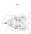
- FIG. 22A shows the relative positional relationship between the handle side receiving member 202 and the main body side receiving member 201 when no pressing force is applied to the handle housing 20 (FIGS. 11 and 12). That is, the relative positional relationship between the handle-side receiving member 202 and the main-body-side receiving member 201 in a no-load state is shown.
- FIG. 10B shows a relative positional relationship between the handle-side receiving member 202 and the main-body-side receiving member 201 when a predetermined pressing force is applied to the handle housing 20 (FIGS. 11 and 12). I have.
- FIG. 10C shows the relative positional relationship between the handle-side receiving member 202 and the main-body-side receiving member 201 when a pressing force exceeding a predetermined magnitude is applied to the handle housing 20 (FIGS. 11 and 12). ing.
- the handle-side receiving member 202 has a substantially U-shape in plan view, and the main-body-side receiving member 201 is disposed inside the handle-side receiving member 202.
- the main body side receiving member 201 is surrounded on three sides (rear, right side and left side) by the handle side receiving member 202.
- the handle-side receiving member 202 has a right arm 203 and a left arm 204 extending from the rear to the front.
- the right arm 203 of the handle side receiving member 202 faces the right side wall 205 of the main body side receiving member 201 with a gap therebetween, and the left arm 204 of the handle side receiving member 202 is located on the left side of the main body side receiving member 201. It faces the wall 206 with a gap.
- a cylindrical rubber 207a as a first elastic body and a cylindrical rubber 208a as a second elastic body are arranged between the right arm 203 and the right wall 205. Further, between the left arm 204 and the left wall 206, a columnar rubber 207b as another first elastic body and a columnar rubber 208b as another second elastic body are arranged. I have.
- the rubber 207a and the rubber 208a are arranged back and forth along the direction of the pressing force applied to the handle housing 20, and the rubber 207b and the rubber 208b are also arranged back and forth along the same direction. Therefore, in the following description, the rubbers 207a and 207b may be referred to as "rear rubbers 207a and 207b".
- the rubbers 208a, 208b may be referred to as "front rubbers 208a, 208b".
- a rear pressing surface 209a and a front pressing surface 210a are provided in the front and rear in this order.
- a rear pressing surface 209b and a front pressing surface 210b are provided on the inner surface of the left arm 204 in this order.
- a rear pressure receiving surface 211a and a front pressure receiving surface 212a are provided on the outer surface of the right side wall 205 in this order.
- a rear pressure receiving surface 211b and a front pressure receiving surface 212b are provided on the outer surface of the left side wall 206 in this order.
- the rear pressing surface 209a and the rear pressure receiving surface 211a are inclined in the same direction, and face each other.
- the rear pressing surface 209b and the rear pressure receiving surface 211b are inclined in the same direction, and face each other.
- the front pressing surface 210a and the front pressure receiving surface 212a are inclined in the same direction, and face each other.
- the front pressing surface 210b and the front pressure receiving surface 212b are inclined in the same direction, and face each other.
- the rear rubber 207a is sandwiched between the opposing rear pressing surface 209a and the rear pressure receiving surface 211a, and the rear rubber 207b is interposed between the opposing rear pressing surface 209b and the rear pressure receiving surface 211b.
- the front rubber 208a is sandwiched between the opposed front pressing surface 210a and the front pressure receiving surface 212a, and the front rubber 208b is sandwiched between the opposed front pressing surface 210b and the front pressure receiving surface 212b. I have.
- FIG. 22A to FIG. 22C are referred to again.
- the rear pressing surfaces 209a and 209b are in contact with the rear rubbers 207a and 207b, respectively.
- a pressing force is applied to the handle housing 20 (FIG. 23), and when the handle housing 20 moves forward, the rear rubbers 207a and 207b are compressed accordingly. That is, the rear rubbers 207a and 207b are compressed in accordance with the distance that the handle housing 20 moves forward.
- the front pressing surfaces 210a, 210b abut against the front rubbers 208a, 208b, respectively.
- the front rubbers 208a and 208b are not compressed, and only the rear rubbers 207a and 207b are compressed. That is, until the pressing force applied to the handle housing 20 reaches a predetermined magnitude, only the rear rubbers 207a and 207b, which are the first elastic members, contribute to vibration isolation.
- the front rubbers 208a and 208b are compressed in addition to the rear rubbers 207a and 207b. That is, when the pressing force applied to the handle housing 20 exceeds a predetermined magnitude, both the rear rubbers 207a and 207b as the first elastic body and the front rubbers 208a and 208b as the second elastic body are compressed, and all of them are compressed. Rubber contributes to vibration isolation.
- the vibration damping structure employed in the hammer drill 1C when no pressing force is applied to the handle housing 20, or when the pressing force applied to the handle housing 20 has a predetermined magnitude.
- the first elastic bodies (rear rubbers 207a, 207b) absorb or attenuate the vibration transmitted from the motor housing 10 to the handle housing 20.
- the pressing force applied to the handle housing 20 exceeds a predetermined magnitude, the first elastic bodies (rear rubbers 207a, 207b) and the second elastic bodies (front rubbers 208a, 208b) are separated from the motor housing 10 by the handle housing 20.
- the anti-vibration structure employed in the hammer drill 1 ⁇ / b> C according to the present embodiment exhibits a sufficient anti-vibration effect even if the presence or absence of the force applied to the handle 21 or the magnitude changes.
- the present invention is not limited to the above embodiment, but can be variously modified without departing from the gist thereof.
- the spring constants of the coil spring 70 in the first embodiment and the outer coil spring 191 in the second embodiment can be appropriately changed.
- a region where only the coil spring 70 contributes to vibration proof a range of the pressing force
- Pressure range can be arbitrarily set.
- the area (the range of the pressing force) that contributes can be set arbitrarily.
- the connecting member that integrates the first housing member and the second housing member may be integral with the first housing member or the second housing member.
- the connecting member 23 can also be integrated.
- the connecting member does not have to penetrate the main body housing.
- the upper connecting member 80 shown in FIG. 2 may pass (cross) over the motor housing 10 and straddle the first housing member 22 and the second housing member 23.
- the lower connecting member 81 may pass (cross) below the motor housing 10 and straddle the first housing member 22 and the second housing member 23.
- the present invention can be applied to power tools other than hammer drills.
- the present invention has the same or substantially the same operation and effect as described above when applied to a power tool other than a hammer drill.
- 1A, 1C Hammer drill, 1B: Hammer, 2: Casing, 3: Tip tool, 10: Body housing (motor housing), 10a: Small diameter portion, 10b: Large diameter portion, 11: Opening, 12: Inner cover, 12a ... Flange part, 13 ... holding hole, 14 ... upper guide part, 15 ... lower guide part, 14a, 15a ... insertion hole, 16a, 16b ... convex part, 20 ... handle housing, 21 ... handle, 22 ... first housing Member, 23: second housing member, 24: trigger lever, 25: trigger switch, 26: third circuit board, 26a: electrolytic capacitor, 27, 28: groove, 30: gear housing, 40: electric motor, 41: stator , 42 ... rotor, 43 ...
- output shaft output shaft
- 44, 45, 51, 52 ... bearing, 46 ... first circuit board, 47 ... second circuit board, 8 cooling fan
- 70 ... coil spring 71 ... rubber (upper rubber), 72 ... rubber (lower rubber), 80 ...
- connecting member upper connecting member
- 80a, 81a flat portion
- 80a, 80b flat portion
- 91a, 91b first handle side regulating surface (handle right regulating surface) .., 91c, 91d...
- First handle side regulating surface handle left regulating surface
- 92 Second handle side regulating surface (handle upper regulating surface, handle lower regulating surface)
Landscapes
- Engineering & Computer Science (AREA)
- Mechanical Engineering (AREA)
- Percussive Tools And Related Accessories (AREA)
- Portable Power Tools In General (AREA)
Abstract
電動工具の部品点数を増やすことなく、電動工具を使用している作業者に伝わる振動を低減させる。ハンマドリルは、電動モータを収容するモータハウジング10と、モータハウジング10に対して進退可能なハンドルハウジング20と、2つのハウジング10,20の間に介在する弾性体(コイルばね70,上側ゴム71,下側ゴム72)と、を有する。ハンドルハウジング20は、モータハウジング10の一部を挟んで対向する第1ハウジング部材および第2ハウジング部材と、モータハウジング10を横断して2つのハウジング部材を連結する上側連結部材80,下側連結部材81と、を含む。弾性体(コイルばね70,上側ゴム71,下側ゴム72)は、ハンドルハウジング20の進退方向において、上側連結部材80,下側連結部材81とモータハウジング10との間に配置される。
Description
本発明は、電動モータを駆動源とする電動工具に関するものである。
電動工具はその使用中に振動が発生する。特に、ハンマドリルやハンマ等の打撃工具は、その使用中に大きな振動が発生する。そこで、打撃工具やその他の電動工具を使用している作業者に伝わる振動を低減させるための防振構造や振動低減構造など(以下「防振構造」と総称する。)が開発されている。
従来の電動工具に採用されている防振構造の一例として、駆動源などが収容される本体ハウジングと作業者によって把持されるハンドルとを相対移動可能に連結するとともに、本体ハウジングとハンドルとの間にゴムやばね等の弾性体を介在させた構造が知られている。例えば、特許文献1には、工具本体側に設けられた第1弾性支持部材と、ハンドル側に設けられた第2弾性支持部材と、これら第1弾性支持部材と第2弾性支持部材との間に設けられた複数の弾性体と、を備える防振構造が記載されている。このような防振構造を備える電動工具では、工具本体ハウジングからハンドルへ伝わる振動が弾性体によって吸収または減衰されるので、ハンドルを把持している作業者の手に伝わる振動が低減される。
しかし、特許文献1に記載されている防振構造では、弾性体を支持するための部材(第1弾性支持部材や第2弾性支持部材)を工具本体側およびハンドル側の双方に設ける必要があり、電動工具の部品点数が多くなってしまう。また、工具本体とハンドルとが弾性体を介して連結されている電動工具では、弾性体のばね定数を小さくするほど大きな防振効果が得られる。しかし、電動工具を使用する際、ハンドルを介して工具本体に力を加え、工具本体に装着されている先端工具を対象物に押し付ける場合がある。つまり、ハンドルに当該ハンドルを工具本体に押し付ける力が加えられる場合がある。よって、工具本体とハンドルとの間に介在する弾性体のばね定数が小さいと、ハンドルに加えられた押付力のみによって弾性体が大きく変形してしまい、十分な防振効果が得られない虞がある。
一方、想定される押付力がハンドルに加えられた状態で十分な防振効果が得られるように弾性体のばね定数を設定した場合、ハンドルに押付力が加えられていない状態では防振効果が小さくなる。そればかりか、ハンドルに押付力が加えられていない状態では、弾性体が設けられていない場合よりも大きな振動が作業者の手に伝わる虞もある。
また、本体ハウジングからハンドルに伝わる振動を上記のような防振構造によって効果的に低減させるためには、本体ハウジングに対するハンドルの円滑な移動を確保する必要がある。そして、本体ハウジングに対してハンドルを円滑に移動させるためには、本体ハウジングとハンドルとの間に隙間(クリアランス)を設ける必要がある。
しかし、本体ハウジングとハンドルとの間に隙間が存在すると、両者の間にガタが生じる。本体ハウジングとハンドルとの間に生じるガタは、電動工具の持ち運び易さを低下させたり、先端工具の位置決め精度を低下させたりする原因となる。以上のように、工具本体とハンドルとの間に弾性体を介在させただけでは、想定される一定の押付力がハンドルに加えられた状態の下でしか十分な防振効果が得られない。
本発明の目的は、電動工具の部品点数を増やすことなく、電動工具を使用している作業者に伝わる振動を低減させることである。本発明の他の目的は、ハンドルに加えられる力の有無や大きさが変化しても十分な防振効果を発揮する防振構造を備えた電動工具を提供することである。
また、本発明の他の目的は、本体ハウジングとハンドルとの円滑な相対移動を妨げることなく、本体ハウジングとハンドルとの間におけるガタの発生が抑制された電動工具を提供することである。
本発明の電動工具は、先端工具の駆動源を収容する本体ハウジングと、作業者に把持される把持部を形成するとともに、前記本体ハウジングに対して進退可能なハンドルハウジングと、前記本体ハウジングと前記ハンドルハウジングとの間に介在する弾性体と、を有する。前記ハンドルハウジングは、前記本体ハウジングの一部を挟んで対向する第1ハウジング部材および第2ハウジング部材と、前記本体ハウジングを横断して前記第1ハウジング部材と前記第2ハウジング部材とに跨る連結部材と、を含む。そして、前記弾性体は、前記ハンドルハウジングの進退方向において、前記連結部材と前記本体ハウジングとの間に配置される。
本発明によれば、電動工具の部品点数を増やすことなく、電動工具を使用している作業者に伝わる振動を低減させることができる。また、本発明によれば、ハンドルに加えられる力の有無や大きさが変化しても十分な防振効果を発揮する防振構造を備えた電動工具が実現される。
また、本発明によれば、本体ハウジングとハンドルとの円滑な相対移動を妨げることなく、本体ハウジングとハンドルとの間におけるガタの発生が抑制された電動工具が実現される。
(第1実施形態)以下、本発明の電動工具の実施形態の一例について図面を参照しながら詳細に説明する。本実施形態に係る電動工具は、切替え可能な複数の動作モードを有するハンマドリルである。本実施形態に係るハンマドリルが有する動作モードには、少なくとも「ドリルモード」,「ハンマモード」および「ハンマドリルモード」の3つの動作モードが含まれる。ドリルモードでは先端工具に回転力のみが付与され、ハンマモードでは先端工具に打撃力のみが付与される。また、ハンマドリルモードでは、先端工具に回転力および打撃力の両方が付与される。ハンマドリルに装着される先端工具の一例としては、ドリルビットが挙げられる。ドリルビットは、例えば、コンクリートや石材などに穴を開けるときに用いられる。もっとも、ハンマドリルに装着される先端工具はドリルビットに限られず、対象物や対象物に対する作業の種類などに応じて適宜交換される。
図1,図2に示されるように、本実施形態に係るハンマドリル1Aは、本体ハウジング10と,本体ハウジング10の一端側に設けられたハンドルハウジング20と、本体ハウジング10の他端側に設けられたギヤハウジング30と、からなるケーシング2を有する。
図3に示されるように、本体ハウジング10には、先端工具3の駆動源である電動モータ40が収容されている。そこで、以下の説明では、本体ハウジング10を「モータハウジング10」と呼ぶ場合がある。
ハンドルハウジング20の一部は、モータハウジング10を部分的に覆っており、ハンドルハウジング20の他の一部は、作業者に把持される把持部(ハンドル21)を形成している。ギヤハウジング30には、電動モータ40から出力される駆動力を先端工具3に伝達する動力伝達系を構成するギヤ等が収容されている。
再び図2を参照する。モータハウジング10は、相対的に径の小さな小径部10aと相対的に径の大きな大径部10bとを有し、全体として略筒形の外観を呈している。モータハウジング10の開口部11にはインナーカバー12が装着されており、このインナーカバー12のフランジ部12aを挟んでモータハウジング10とギヤハウジング30とが突き合わされている。
つまり、ハンドルハウジング20はモータハウジング10の軸方向一端側に設けられ、ギヤハウジング30はモータハウジング10の軸方向他端側に設けられている。言い換えれば、モータハウジング10は、ハンドルハウジング20とギヤハウジング30との間に挟まれている。以下の説明では、モータハウジング10を基準として、ハンドルハウジング20が設けられている側を「後方」、ギヤハウジング30が設けられている側を「前方」とする。つまり、ハンドルハウジング20,モータハウジング10およびギヤハウジング30は、後方から前方に向かってこの順で並んでいる。
図3に示されるように、モータハウジング10に収容されている電動モータ40は、固定子(ステータ41)と、ステータ41の内側に回転可能に設けられた回転子(ロータ42)と、ロータ42に固定された出力軸(出力シャフト43)と、を有するブラシレスモータである。電動モータ40の大部分は、モータハウジング10の小径部10aに収容されている。
電動モータ40の出力シャフト43はロータ42を貫通して前後方向に延びている。言い換えれば、前後方向とは、出力シャフト43の方向と平行な方向(図3の紙面左右方向)である。また、前後方向とは、先端工具3の長手方向に沿う方向でもある。出力シャフト43の後端側は、モータハウジング10の底部に設けられている軸受44により回転可能に支持されており、出力シャフト43の先端側は、インナーカバー12に保持されている軸受45により回転可能に支持されている。モータハウジング10内には、電動モータ40に加えて、第1回路基板46,第2回路基板47および冷却ファン48が収容されている。これら第1回路基板46,第2回路基板47および冷却ファン48は、モータハウジング10の大径部10bに収容されている。
電動モータ40の出力シャフト43の先端側は、第1回路基板46,第2回路基板47および冷却ファン48をこの順で貫通して軸受45に至っている。さらに、出力シャフト43の先端側は、インナーカバー12を貫通してギヤハウジング30内に進入している。ギヤハウジング30内に進入している出力シャフト43の先端には第1ギヤ49が設けられている。
モータハウジング10に収容されている第1回路基板46にはスイッチング素子を含む駆動回路が搭載され、第2回路基板47にはホール素子を含む制御回路が搭載されている。また、冷却ファン48は出力シャフト43に対して相対回転不能に固定されており、出力シャフト43が回転すると冷却ファン48も回転する。ここで、ハンドルハウジング20およびモータハウジング10には複数の風窓が設けられている。冷却ファン48が回転すると、ハンドルハウジング20に設けられている風窓を通してハンドルハウジング20内に空気が流入する。ハンドルハウジング20内に流入した空気は、モータハウジング10に設けられている風窓を通してモータハウジング10内に流入する。モータハウジング10内に流入した空気は、電動モータ40,第1回路基板46および第2回路基板47をこの順で通過する。つまり、出力シャフト43の回転に伴って冷却ファン48が回転すると、ケーシング2内を後方から前方に向かって流れる冷却風が発生し、電動モータ40,第1回路基板46および第2回路基板47が冷却される。尚、ハンドルハウジング20内には、電解コンデンサ26aと繋がる整流回路が搭載された第3回路基板26(図4)も収容されており、これら電解コンデンサ26aや第3回路基板26も上記冷却風によって冷却される。
図2に示されるように、ハンドルハウジング20は、モータハウジング10の一部(小径部10a)を挟んで対向する2つのハウジング部材(第1ハウジング部材22,第2ハウジング部材23)から構成されている。ここで、第1ハウジング部材22と第2ハウジング部材23の対向方向と平行な方向を左右方向と定義する。また、左右方向および前後方向の双方と交差する方向を上下方向と定義する。つまり、図示されているハンドル21は、上下方向に延在している。
図3に示されるように、ハンドル21にはトリガレバー24が設けられており、トリガレバー24の背後(ハンドルハウジング20の内部)には、トリガスイッチ25が設けられている。トリガレバー24の操作に伴ってトリガスイッチ25がONされると、電動モータ40に電力が供給され、ロータ42および出力シャフト43が回転する。一方、トリガレバー24の操作に伴ってトリガスイッチ25がOFFされると、電動モータ40に対する電力供給が停止され、ロータ42および出力シャフト43の回転が停止する。図1,図2に示されるように、ギヤハウジング30は略円筒形状を有する。図3に示されるように、ギヤハウジング30内には、出力シャフト43と平行に中間シャフト50が収容されている。中間シャフト50の後端は軸受51により回転可能に支持され、先端は軸受52により回転可能に支持されている。中間シャフト50の後端側には、出力シャフト43に設けられている第1ギヤ49と常に噛合う第2ギヤ53が設けられている。
中間シャフト50上には、当該中間シャフト50の回転運動を往復運動に変換する変換機構54が設けられている。変換機構54は、内輪,外輪,転動体および連結棒から構成されている。内輪は中間シャフト50に取り付けられ、外輪は内輪の周囲に設けられ、転動体は内輪と外輪との間に介在し、連結棒は外輪に一体成形されている。内輪の外周面および外輪の内周面には、互いに交差する断面円弧状の溝がそれぞれ形成されている。転動体は、一部が内輪に形成されている溝に嵌合し、他の一部が外輪に形成されている溝に嵌合した状態で内輪と外輪との間に介在している。言い換えれば、内輪と外輪とは転動体を介して相対回転可能に連結されている。
また、中間シャフト50上には、当該中間シャフト50から変換機構54に動力が伝達される締結状態と、中間シャフト50から変換機構54に動力が伝達されない解放状態と、に切り替え可能なクラッチ55が設けられている。
クラッチ55は、中間シャフト50に対して相対回転不能であるとともに、中間シャフト50に沿って前後に移動可能である。クラッチ55が所定位置まで後退すると(内輪に近接すると、)、中間シャフト50と内輪とがクラッチ55を介して接続され、中間シャフト50から内輪に動力が伝達される。一方、クラッチ55が所定位置まで前進すると(内輪から離間すると、)、中間シャフト50と内輪との接続が解除され、中間シャフト50から内輪への動力伝達が遮断される。かかるクラッチ55の切り替えは、作業者によるモード切替操作に応じて実現される。クラッチ55が締結状態のときに中間シャフト50が回転すると内輪が回転する。すると、内輪の表面に沿って外輪が転動し、これに伴って連結棒が前後に揺動する。
中間シャフト50上であってクラッチ55の前方には、第3ギヤ56が設けられている。第3ギヤ56は中間シャフト50に沿って前後に移動可能である。第3ギヤ56が所定位置まで前進すると、第3ギヤ56と中間シャフト50とがスプライン嵌合する。一方、第3ギヤ56が所定位置まで後退すると、第3ギヤ56と中間シャフト50とのスプライン嵌合が解除される。つまり、第3ギヤ56は、中間シャフト50に沿って前後に移動可能であり、中間シャフト50と一体的に回転する連結状態と、中間シャフト50が回転しても回転しない非連結状態と、に切り替わる。かかる第3ギヤ56の切り替えは、作業者によるモード切替操作に応じて実現される。
ギヤハウジング30内には、出力シャフト43および中間シャフト50と平行にシリンダ60が収容されている。シリンダ60には、ピストン61,打撃子62,中間子63が収容されている。これらピストン61,打撃子62,中間子63は、後方から前方に向かってこの順で一列に並んでおり、ピストン61と打撃子62との間には空気室64が設けられている。シリンダ60の前方には、保持部としてのリテーナスリーブ65が設けられている。リテーナスリーブ65の後端部はシリンダ60の先端部に連結されており、シリンダ60とリテーナスリーブ65とは相対回転不能に固定されている。リテーナスリーブ65には、先端工具3の根元部が挿入される。リテーナスリーブ65は、挿入された先端工具の根元部を所定範囲内で直動可能に保持する。
ピストン61の背面には、変換機構54の連結棒が回動可能に連結されており、連結棒が前後に揺動すると、ピストン61がシリンダ60内で前後に往復動する。また、シリンダ60の外周面には、中間シャフト50に設けられている第3ギヤ56と選択的に噛合う第4ギヤ66が設けられている。具体的には、作業者によるモード切替操作によって第3ギヤ56が連結状態に切り替えられると、当該第3ギヤ56と第4ギヤ66とが噛み合う。すると、中間シャフト50の回転力が第3ギヤ56および第4ギヤ66を介してシリンダ60に伝達され、シリンダ60が回転する。一方、作業者によるモード切替操作によって第3ギヤ56が非連結状態に切り替えられると、第3ギヤ56と第4ギヤ66との噛み合いが解除される。すると、中間シャフト50からシリンダ60への回転力の伝達が遮断される。
本実施形態では、作業者によるモード切替操作によってドリルモードが選択されると、クラッチ55が解放状態となり、第3ギヤ56が連結状態となる。この状態で中間シャフト50が回転すると、変換機構54の内輪は回転しない一方、シリンダ60は回転する。この結果、リテーナスリーブ65に保持されている先端工具3に回転力のみが付与される。
一方、作業者によるモード切替操作によってハンマモードが選択されると、クラッチ55が締結状態となり、第3ギヤ56が非連結状態となる。この状態で中間シャフト50が回転すると、内輪は回転する一方、シリンダ60は回転しない。よって、静止しているシリンダ60内でピストン61が往復動し、空気室64の圧力が変動する。すると、空気室64の圧力変動によって打撃子62が駆動され、打撃子62によって中間子63が打撃され、中間子63によって先端工具3が打撃される。この結果、リテーナスリーブ65に保持されている先端工具3に打撃力のみが付与される。
また、作業者によるモード切替操作によってハンマドリルモードが選択されると、クラッチ55が締結状態となり、第3ギヤ56が連結状態となる。この状態で中間シャフト50が回転すると、変換機構54の内輪が回転し、かつ、シリンダ60も回転する。よって、回転するシリンダ60内でピストン61が往復動する。この結果、リテーナスリーブ65に保持されている先端工具3に回転力および打撃力の両方が付与される。
次に、本実施形態に係るハンマドリル1Aに採用されている防振構造について説明する。図1に示されているモータハウジング10とハンドルハウジング20とは、出力シャフト43(図3)の方向に相対移動可能に連結されている。言い換えれば、ハンドルハウジング20は、モータハウジング10に対して前後方向に進退可能である。図4に示されるように、モータハウジング10とハンドルハウジング20との間には約3.0mmの隙間D1が設けられており、ハンドルハウジング20は、隙間D1の範囲内でモータハウジング10に対して進退可能である。
一方、モータハウジング10とハンドルハウジング20との間には、第1の弾性体としてのコイルばね70と、第2の弾性体としてのゴム71,72と、が介在している。ゴム71とゴム72は、上下方向において互いに異なる位置に配置されている。具体的には、ゴム71はモータハウジング10の上部に配置されており、上側弾性体に相当する。一方、ゴム72はモータハウジング10の下部に配置されており、下側弾性体に相当する。そこで、以下の説明では、ゴム71を「上側ゴム71」、ゴム72を「下側ゴム72」と呼ぶ場合がある。尚、コイルばね70は、下側ゴム72と略同一の高さに配置されている。
コイルばね70は、ハンドルハウジング20内のリブとモータハウジング10の底部との間に配置されている。コイルばね70の一端(先端)は、モータハウジング10の底部に当接し、コイルばね70の他端(後端)はハンドルハウジング20のリブに当接している。つまり、コイルばね70の一端(先端)はモータハウジング10に常時当接し、コイルばね70の他端(後端)はハンドルハウジング20に常時当接している。よって、コイルばね70は、モータハウジング10に対するハンドルハウジング20の進退に伴って伸縮する。また、コイルばね70にはプリロードが与えられている。言い換えれば、コイルばね70は、モータハウジング10とハンドルハウジング20との間に圧縮状態で配置されている。このため、モータハウジング10およびハンドルハウジング20には、これらを互いに離間させる方向に作用する力が加えられている。つまり、ハンドルハウジング20は後方に向けて付勢されており、モータハウジング10は前方に向けて付勢されている。よって、ハンドルハウジング20に、当該ハンドルハウジング20をモータハウジング10に近接させる方向(前方)に作用する押付力が加えられていないとき、隙間D1が最大となる。言い換えれば、ハンドルハウジング20に押付力が加えられていないとき、当該ハンドルハウジング20はモータハウジング10に対して最も後退する。以下の説明では、ハンドルハウジング20に押付力が加えられておらず、よって隙間D1が最大である状態を「無負荷状態」と呼ぶ場合がある。また、無負荷状態におけるコイルばね70の全長を「セット長」と呼ぶ場合がある。もっとも、コイルばね70にはプリロードが与えられているので、コイルばね70の「セット長」はコイルばね70の「自然長」よりも短い。本実施形態では、コイルばね70に2.5Kgfのプリロードが与えられている。この結果、コイルばね70は、自然長に対して1.0mm圧縮されている。つまり、コイルばね70のセット長は、自然長-1.0mmである。
図4に示されるように、上側ゴム71および下側ゴム72の一端(先端)はモータハウジング10に常時当接している。具体的には、上側ゴム71および下側ゴム72の一部(先端側)は、モータハウジング10に設けられている保持穴13にそれぞれ嵌合されている。一方、無負荷状態のとき、上側ゴム71および下側ゴム72の後端側には何も当接していない。
図2を参照する。図示されている第1ハウジング部材22および第2ハウジング部材23は、モータハウジング10を横断して第1ハウジング部材22と第2ハウジング部材23とを連結する2つの連結部材(上側連結部材80,下側連結部材81)を介して互いに固定され、一体化されている。上側連結部材80および下側連結部材81は、ハンドルハウジング20の進退方向(前後方向)と直交する左右方向に延びる柱状に形成されており、その外面の一部には平坦部80a,81aが設けられている。
上側連結部材80は、モータハウジング10の上部に設けられているトンネル状の穴部としての上側ガイド部14に挿通されており、その一端は第1ハウジング部材22に固定され、その他端は第2ハウジング部材23に固定されている。下側連結部材81は、モータハウジング10の下部に設けられているトンネル状の他の穴部としての下側ガイド部15(図4)に挿通されており、その一端は第1ハウジング部材22に固定され、その他端は第2ハウジング部材23に固定されている。より具体的には、上側連結部材80の一方の端部は、第1ハウジング部材22の内側に設けられている凹部に嵌合しており、上側連結部材80の他方の端部は、第2ハウジング部材23の内側に設けられている凹部に嵌合している。また、平坦部80aを含む上側連結部材80の中間部は、上側ガイド部14の挿通穴14a(図4)を貫通している。
同様に、下側連結部材81の一方の端部は、第1ハウジング部材22の内面に設けられている凹部に嵌合しており、下側連結部材81の他方の端部は、第2ハウジング部材23の内面に設けられている凹部に嵌合している。また、平坦部81aを含む下側連結部材81の中間部は、下側ガイド部15の挿通穴15a(図4)を貫通している。
第1ハウジング部材22は、当該第1ハウジング部材22を貫通して上側連結部材80および下側連結部材81の一方の端部にそれぞれねじ結合された固定具(ねじ)によってそれぞれの連結部材80,81に固定されている。第2ハウジング部材23は、当該第2ハウジング部材23を貫通して上側連結部材80および下側連結部材81の他方の端部にそれぞれねじ結合された固定具(ねじ)によってそれぞれの連結部材80,81に固定されている。つまり、第1ハウジング部材22および第2ハウジング部材23は、共通の連結部材80,81に固定されることによって一体化されている。
上記のように、本実施形態における上側連結部材80および下側連結部材81は、第1ハウジング部材22および第2ハウジング部材23とは別体である。言い換えれば、上側連結部材80および下側連結部材81は、ハンドルハウジング20とは別体である。しかし、第1ハウジング部材22と第2ハウジング部材23とは上記のような固定構造によって互いに固定されている。つまり、上側連結部材80および下側連結部材81は、第1ハウジング部材22および第2ハウジング部材23と共にハンドルハウジング20を形成しており、ハンドルハウジング20の一部である。
再び図4を参照する。上側連結部材80の平坦部80aは、ハンドルハウジング20の進退方向において上側ゴム71の後端面と対向する押圧面を形成している。一方、下側連結部材81の平坦部81aは、ハンドルハウジング20の進退方向において下側ゴム72の後端面と対向する押圧面を形成している。言い換えれば、上側ゴム71は、上側ガイド部14の挿通穴14aの内側において、上側連結部材80の平坦部80aと対向している。また、下側ゴム72は、下側ガイド部15の挿通穴15aの内側において、下側連結部材81の平坦部81aと対向している。つまり、上側ゴム71および下側ゴム72は、ハンドルハウジング20の進退方向(前後方向)において、連結部材(上側連結部材80,下側連結部材81)とモータハウジング10との間に配置されている。
もっとも、無負荷状態では、上側連結部材80の平坦部80aと上側ゴム71との間、および下側連結部材81の平坦部81aと下側ゴム72との間には約1.5mmの隙間D2が存在している。つまり、無負荷状態では、上側連結部材80は上側ゴム71に接触しておらず、下側連結部材81は下側ゴム72に接触していない。一方、ハンドルハウジング20に押付力が加えられ、上側連結部材80および下側連結部材81を含むハンドルハウジング20がコイルばね70の付勢に抗して前進すると、隙間D2が減少し、上側連結部材80の平坦部80aが上側ゴム71に、下側連結部材81の平坦部81aが下側ゴム72に、それぞれ当接する。
しかし、ハンドルハウジング20は、コイルばね70によって後方に向けて付勢されている。具体的には、圧縮状態のコイルばね70の先端はモータハウジング10に常時当接し、後端はハンドルハウジング20に常時当接している。よって、ハンドルハウジング20が前進すると(モータハウジング10に近接すると、)、これに伴ってコイルばね70がさらに圧縮される。つまり、コイルばね70の全長は、ハンドルハウジング20の前方への移動距離と同じ長さだけ減少する。そして、全長が所定長に達するまでコイルばね70が圧縮されると、上側連結部材80の平坦部80aが上側ゴム71に当接し、下側連結部材81の平坦部81aが下側ゴム72に当接する。
ここで、挿通穴14aおよび挿通穴15aの内寸は、上下方向の幅が前後方向の幅よりも小さい(狭い)。このため、上側連結部材80のおよび下側連結部材81は、挿通穴14aおよび挿通穴15aによって上下方向への移動が規制され、専ら前後方向に移動する。尚、上下方向の幅とは、前後方向(進退方向)および左右方向と直交する方向の幅である(図4の紙面上下方向の幅である。)。
本実施形態では、図4に示される隙間D1が約3.0mm、隙間D2が約1.5mmに設定されている。よって、図5に示されるように、隙間D1が約1.5mmに減少するまでハンドルハウジング20が前進すると(モータハウジング10に近接すると、)、上側連結部材80が上側ゴム71に当接し、下側連結部材81が下側ゴム72に当接する。その後、図6に示されるように、ハンドルハウジング20がさらに前進すると(モータハウジング10にさらに近接すると、)、上側連結部材80によって上側ゴム71が圧縮され、下側連結部材81によって下側ゴム72が圧縮される。
言い換えれば、全長が所定長(セット長-1.5mm)に達するまでコイルばね70が圧縮されると、上側連結部材80が上側ゴム71に当接し、下側連結部材81が下側ゴム72に当接する。その後、コイルばね70がさらに圧縮され、コイルばね70の全長が上記所定長を下回ると、上側連結部材80によって上側ゴム71が圧縮され、下側連結部材81によって下側ゴム72が圧縮される。尚、全長が所定長(セット長-1.5mm)に達するまでコイルばね70を圧縮するのに必要な押付力の大きさは、コイルばね70のばね定数に基づいて予め設定することができる。本実施形態におけるコイルばね70のばね定数は2.5kgf/mmであり、プリロードは2.5kgfである。よって、ハンドルハウジング20に加えられる押付力が2.5kgfに達すると、コイルばね70の圧縮が開始される。また、ハンドルハウジング20に加えられる押付力が6.5kgfに達すると、上側連結部材80が上側ゴム71に当接し、下側連結部材81が下側ゴム72に当接する。さらに、ハンドルハウジング20に加えられる押付力が6.5kgfを上回ると、上側連結部材80によって上側ゴム71が圧縮され、下側連結部材81によって下側ゴム72が圧縮される。言い換えれば、ハンドルハウジング20に加えられる押付力が2.5kgfを超えて6.5kgfに達するまではコイルばね70のみが圧縮され、押付力が6.5kgfを上回った後は、コイルばね70に加えて上側ゴム71および下側ゴム72が圧縮される。
尚、図7に示されるように、モータハウジング10の両側には、長手方向に沿って延びる凸部16a,16bが形成されている。一方、第1ハウジング部材22の内側には、凸部16aを受け入れる溝27が形成されており、第2ハウジング部材23の内側には、凸部16bを受け入れる溝28が形成されている。第1ハウジング部材22および第2ハウジング部材23から構成されるハンドルハウジング20は、モータハウジング10に設けられている一対の凸部16a,16bに案内されて、当該モータハウジング10に対して前後に移動する。
上記のように、本実施形態に係るハンマドリル1Aに採用されている防振構造では、ハンドルハウジング20に押付力が加えられていないとき、またはハンドルハウジング20に加えられる押付力が所定の大きさを下回っているときには、第1の弾性体(コイルばね70)のみがモータハウジング10からハンドルハウジング20へ伝わる振動を吸収ないし減衰させる。一方、ハンドルハウジング20に加えられる押付力が所定の大きさを上回ると、第1の弾性体(コイルばね70)および第2の弾性体(上側ゴム71,下側ゴム72)がモータハウジング10からハンドルハウジング20へ伝わる振動を吸収ないし減衰させる。よって、本実施形態に係るハンマドリル1Aに採用されている防振構造は、ハンドル21に加えられる力の有無や大きさが変化しても十分な防振効果を発揮する。
モータハウジング10からハンドルハウジング20へ伝わる振動を上記防振構造によって効果的に低減または減衰させるためには、モータハウジング10に対するハンドルハウジング20の円滑な移動を確保する必要がある。具体的には、モータハウジング10とハンドルハウジング20との間に隙間(クリアランス)を設ける必要がある。
しかし、モータハウジング10とハンドルハウジング20との間に隙間が存在すると、モータハウジング10とハンドルハウジング20との間でガタが生じる。かかるガタは、ハンドル21に押付力が加えられていない無負荷状態において生じ易い一方、ハンドル21に押付力が加えられている負荷状態においては生じ難い。
そこで、本実施形態に係るハンマドリル1Aには、少なくとも無負荷状態のときに機能し、モータハウジング10とハンドルハウジング20との間におけるガタの発生を抑制または防止する規制手段が設けられている。尚、無負荷状態のとき、ハンドルハウジング20はモータハウジング10に対して最も後退している。言い換えれば、無負荷状態のとき、図4等に示されている隙間D1は最大となる。
本実施形態に係るハンマドリル1Aが備える規制手段は、モータハウジング10およびハンドルハウジング20に設けられた複数の規制面から構成されている。具体的には、図8,図9に示されるように、ハンドルハウジング20には複数のハンドル側規制面90が設けられている。一方、図10,図11に示されるように、モータハウジング10には複数の本体側規制面100が設けられている。以下、ハンドルハウジング20に設けられているハンドル側規制面90について詳細に説明し、次いで、モータハウジング10に設けられている本体側規制面100について詳細に説明する。
ハンドル側規制面90には、ハンドルハウジング20の内側に突設されたリブの表面の一部によって形成される第1ハンドル側規制面と、連結部材80,81の外面の一部によって形成される第2ハンドル側規制面と、が含まれる。図8に示されるように、第1ハウジング部材22の内側には2つの第1ハンドル側規制面91a,91bが設けられている。また、図9に示されるように、第2ハウジング部材23の内側には2つの第1ハンドル側規制面91c,91dが設けられている。以下の説明では、第1ハウジング部材22に設けられている第1ハンドル側規制面91a,91bを「ハンドル右側規制面91a,91b」と呼び、第2ハウジング部材23に設けられている第1ハンドル側規制面91c,91dを「ハンドル左側規制面91c,91d」と呼ぶ場合がある。
ハンドル右側規制面91aとハンドル左側規制面91cとは同じ高さに位置しており、ハンドル右側規制面91bとハンドル左側規制面91dとは同じ高さに位置している。ハンドル右側規制面91aとハンドル右側規制面91bとは、第1ハウジング部材22における、本体ハウジング10を覆う一部の内面に形成される。ハンドル左側規制面91cとハンドル左側規制面91dとは、第2ハウジング部材23における、本体ハウジング10を覆う一部の内面に形成されているる。また、第1ハンドル側規制面91a~91dは同じ方向に傾斜している。具体的には、第1ハンドル側規制面91a~91dは、前後方向および左右方向に対して傾斜している一方、上下方向に対しては平行である。
図8、図9に示されるように、第1ハウジング部材22及び第2ハウジング部材23における、本体ハウジング10を覆う一部の内面には、複数のハンドル側レール部が設けられる。具体的には、第1ハウジング部材22における、本体ハウジング10を覆う一部の内面には、左側に向かって突出する上側レール部93および下側レール部94が形成されている。また、第2ハウジング部材23における、本体ハウジング10を覆う一部の内面には、右側に向かって突出する上側レール部95および下側レール部96が形成されている。上側レール部93、95および下側レール部94、96は、後述する本体ハウジングに設けられた複数の本体側レール部と対応する位置に配置されており、互いに摺動するように組み合わされる。
図8に示されるように、上側連結部材80には、押圧面(平坦部80a)を形成している外面の一部とは異なる他の一部によって第2ハンドル側規制面92が形成されている。同様に、下側連結部材81には、押圧面(平坦部81a)を形成している外面の一部とは異なる他の一部によって第2ハンドル側規制面92が形成されている。以下の説明では、上側連結部材80に設けられている第2ハンドル側規制面92を「ハンドル上側規制面92」と呼び、下側連結部材81に設けられている第2ハンドル側規制面92を「ハンドル下側規制面92」と呼ぶ場合がある。
図15(a),(b)に示されるように、ハンドル上側規制面92およびハンドル下側規制面92には、後方から前方に向かって上り傾斜の上向き規制面92aと、後方から前方に向かって下り傾斜の下向き規制面92bと、が含まれる。そして、上側連結部材80に設けられている上向き規制面92a(図15(a))と、下側連結部材81に設けられている上向き規制面92a(図15(b))と、は同じ方向に傾斜している。具体的には、それぞれの上向き規制面92aは、前後方向および上下方向に対して傾斜している一方、左右方向に対しては平行である。また、上側連結部材80に設けられている下向き規制面92b(図15(a))と、下側連結部材81に設けられている下向き規制面92b(図15(b))と、は同じ方向に傾斜している。具体的には、それぞれの下向き規制面92bは、前後方向および上下方向に対して傾斜している一方、左右方向に対しては平行である。
以上のように、ハンドルハウジング20には複数のハンドル側規制面90が設けられている。そして、複数のハンドル側規制面90には、第1ハウジング部材22に設けられている第1ハンドル側規制面(ハンドル右側規制面)91a,91bと、第2ハウジング部材23に設けられている第1ハンドル側規制面(ハンドル左側規制面)91c,91dと、それぞれの連結部材80,81に設けられている第2ハンドル側規制面92と、が含まれる。さらに、それぞれの第2ハンドル側規制面92には、上向き規制面92aおよび下向き規制面92bが含まれる。
第1ハウジング部材22または第2ハウジング部材23に設けられている第1ハンドル側規制面91a~91dは、前後方向および左右方向に対して傾斜し、かつ、上下方向に対して平行である。一方、それぞれの連結部材80,81に設けられている第2ハンドル側規制面92は、前後方向および上下方向に対して傾斜し、かつ、左右方向に対して平行である。
次に、モータハウジング10に設けられている本体側規制面100について説明する。本体側規制面100には、モータハウジング10の外側に突設されたリブの表面の一部によって形成される第1本体側規制面と、モータハウジング10の上側ガイド部14および下側ガイド部15の内面の一部によって形成される第2本体側規制面と、が含まれる。
図10に示されるように、第1ハウジング部材22(図8)に覆われるモータハウジング10の右側面には、2つの第1本体側規制面101a,101bが設けられている。また、図11に示されるように、第2ハウジング部材23(図9)に覆われるモータハウジング10の左側面には、2つの第1本体側規制面101c,101dが設けられている。以下の説明では、モータハウジング10の右側面に設けられている第1本体側規制面101a,101bを「本体右側規制面101a,101b」と呼び、モータハウジング10の左側面に設けられている第1本体側規制面101c,101dを「本体左側規制面101c,101d」と呼ぶ場合がある。
本体右側規制面101aと本体左側規制面101cとは同じ高さに位置しており、本体右側規制面101bと本体左側規制面101dとは同じ高さに位置している。さらに、本体右側規制面101aは、ハンドル右側規制面91a(図8)と同じ高さに位置し、当該ハンドル右側規制面91aと対向している。以下同様に、本体左側規制面101c(図11)は、ハンドル左側規制面91c(図9)と同じ高さに位置し、当該ハンドル左側規制面91cと対向している。本体右側規制面101b(図10)は、ハンドル右側規制面91b(図8)と同じ高さに位置し、当該ハンドル右側規制面91bと対向している。本体左側規制面101d(図11)は、ハンドル左側規制面91d(図9)と同じ高さに位置し、当該ハンドル左側規制面91dと対向している。
図10、図11に示されるように、モータハウジング10には、複数の本体側レール部が設けられている。具体的には、モータハウジング10は、右側に向かって突出する右上側レール部103および右下側レール部104と、左側に向かって突出する左上側レール部105および左下側レール部106と、が設けられている。本体側レール部とハンドル側レール部とは、それぞれが対応する位置に配置され、互いに摺動するように組み合わされる。具体的には、右上側レール部103は上側レール部93と、右下側レール部104は下側レール部94と、左上側レール部105は上側レール部95と、左下側レール部106は下側レール部96と、それぞれ対応する位置に配置されており、互いに摺動可能に組み合わされている。このように、規制面の傾斜方向と同一方向に突出する本体側レール部およびハンドル側レール部を設けることで、本体ハウジング(モータハウジング)10に対するハンドルハウジング20の進退をスムーズにするとともに、規制面とレール部を単一の型で成形できるため、安価に製造できる。また、本体ハウジング10を覆うハンドルハウジング20の内面に規制面と複数のハンドル側レール部とを設けることで、ハンドルハウジング20に別途規制面と複数のハンドル側レール部を設ける構成と比較して、ハンドルハウジング20の大型化を抑制でき、強度も確保できる。
また、図10,図11に示されるように、第1本体側規制面101a~101dは同じ方向に傾斜している。具体的には、第1本体側規制面101a~101dは、前後方向および左右方向に対して傾斜している一方、上下方向に対しては平行である。かかる第1本体側規制面101a~101dの傾斜は、図8,図9に示される第1ハンドル側規制面91a~91dの傾斜と同様である。つまり、第1本体側規制面101a~101dは、第1ハンドル側規制面91a~91dに沿う傾斜面である。言い換えれば、第1ハンドル側規制面91a~91dは、第1本体側規制面101a~101dに沿う傾斜面である。
図10,図11に示されるように、上側ガイド部14の内側には、その内面の平坦な一部によって第2本体側規制面102が形成されている。下側ガイド部15の内側にも、その内面の平坦な一部によって第2本体側規制面102が形成されている。以下の説明では、上側ガイド部14に設けられている第2本体側規制面102を「本体上側規制面102」と呼び、下側ガイド部15に設けられている第2本体側規制面102を「本体下側規制面102」と呼ぶ場合がある。
図15(a),(b)に示されるように、上側ガイド部14および下側ガイド部15に設けられている本体上側規制面102には、後方から前方に向かって上り傾斜の上向き規制面102aと、後方から前方に向かって下り傾斜の下向き規制面102bと、がそれぞれ含まれる。上側ガイド部14に設けられている上向き規制面102a(図15(a))と、下側ガイド部15に設けられている上向き規制面102a(図15(b))と、は同じ方向に傾斜している。具体的には、それぞれの上向き規制面102aは、前後方向および上下方向に対して傾斜している一方、左右方向に対しては平行である。また、上側ガイド部14に設けられている下向き規制面102b(図15(a))と、下側ガイド部15に設けられている下向き規制面102b(図15(b))と、は同じ方向に傾斜している。具体的には、それぞれの下向き規制面102bは、前後方向および上下方向に対して傾斜している一方、左右方向に対しては平行である。
ここで、上側ガイド部14に設けられている本体上側規制面102(上向き規制面102aおよび下向き規制面102b)の傾斜は、上側連結部材80に設けられているハンドル上側規制面92(上向き規制面92aおよび下向き規制面92b)の傾斜に対応している。また、下側ガイド部15に設けられている本体下側規制面102(上向き規制面102aおよび下向き規制面102b)の傾斜は、下側連結部材81に設けられているハンドル下側規制面92(上向き規制面92aおよび下向き規制面92b)の傾斜に対応している。さらに、上側ガイド部14の上向き規制面102aおよび下向き規制面102bと、上側連結部材80の上向き規制面92aおよび下向き規制面92bと、は互いに対向している。同じく、下側ガイド部15の上向き規制面102aおよび下向き規制面102bと、下側連結部材81の上向き規制面92aおよび下向き規制面92bと、は互いに対向している。つまり、第2本体側規制面102は、第2ハンドル側規制面92に沿って傾斜する平面である。言い換えれば、第2ハンドル側規制面92は、第2本体側規制面102に沿って傾斜する平面である。
以上のように、モータハウジング10には複数の本体側規制面100が設けられている。そして、複数の本体側規制面100には、モータハウジング10の右側面に設けられている第1本体側規制面(本体右側規制面)101a,101bと、モータハウジング10の左側面に設けられている第1本体側規制面(本体左側規制面)101c,101dと、上側ガイド部14および下側ガイド部15にそれぞれ設けられている第2本体側規制面102と、が含まれる。さらに、それぞれの第2本体側規制面102には、上向き規制面102aおよび下向き規制面102bが含まれる。
また、第1本体側規制面101a~101dは、前後方向および左右方向に対して傾斜し、かつ、上下方向に対して平行である。一方、第2本体側規制面102は、前後方向および上下方向に対して傾斜し、かつ、左右方向に対して平行である。
図12,図13は、無負荷状態のときの、ハンドル側規制面90(図8,図9)と本体側規制面100(図10,図11)との位置関係を示す図である。既述のとおり、無負荷状態のとき、ハンドルハウジング20は、コイルばね70(図4)の付勢により、モータハウジング10に対して最も後退している。
図12(a)に示されるように、無負荷状態のとき、ハンドル右側規制面91aは本体右側規制面101aに当接し、ハンドル左側規制面91cは本体左側規制面101cに当接している。図12(b)に示されるように、無負荷状態のとき、ハンドル右側規制面91bは本体右側規制面101bに当接し、ハンドル左側規制面91dは本体左側規制面101dに当接している。
図13(a)に示されるように、無負荷状態のとき、ハンドル上側規制面92は本体上側規制面102に当接している。より詳細には、ハンドル上側規制面92の上向き規制面92aは、本体上側規制面102の上向き規制面102aに当接し、ハンドル上側規制面92の下向き規制面92bは、本体上側規制面102の下向き規制面102bに当接している。
図13(b)に示されるように、無負荷状態のとき、ハンドル下側規制面92は本体下側規制面102に当接している。より詳細には、ハンドル下側規制面92の上向き規制面92aは、本体下側規制面102の上向き規制面102aに当接し、ハンドル下側規制面92の下向き規制面92bは、本体下側規制面102の下向き規制面102bに当接している。
以上のように、無負荷状態のときには、複数のハンドル側規制面90が、それぞれ対応する本体側規制面100に当接する。この結果、ハンドルハウジング20がモータハウジング10に対してガタつくことが防止され、又は抑制される。具体的には、第1ハンドル側規制面91a~91dが第1本体側規制面101a~101dに当接することにより、ハンドルハウジング20の左右方向のガタつきが防止または抑制され、第2ハンドル側規制面92が第2本体側規制面102に当接することにより、ハンドルハウジング20の上下方向のガタつきが防止または抑制される。尚、ハンドルハウジング20の前後方向のガタつきは、コイルばね70の付勢によって防止または抑制されている。
図14,図15は、負荷状態のときの、ハンドル側規制面90(図8,図9)と本体側規制面100(図10,図11)との位置関係を示す図である。負荷状態のとき、ハンドルハウジング20は、コイルばね70(図4)の付勢に抗してモータハウジング10に対して前進している。
図14(a)に示されるように、無負荷状態から負荷状態に移行すると、それまで本体右側規制面101aに当接していたハンドル右側規制面91aは、本体右側規制面101aから離間する。また、それまで本体左側規制面101cに当接していたハンドル左側規制面91cは、本体左側規制面101cから離間する。図14(b)に示されるように、無負荷状態から負荷状態に移行すると、それまで本体右側規制面101bに当接していたハンドル右側規制面91bは、本体右側規制面101bから離間する。また、それまで本体左側規制面101dに当接していたハンドル左側規制面91dは、本体左側規制面101dから離間する。
図15(a)に示されるように、無負荷状態から負荷状態に移行すると、それまで本体上側規制面102に当接していたハンドル上側規制面92は、本体上側規制面102から離間する。より詳細には、ハンドル上側規制面92の上向き規制面92aは、本体上側規制面102の上向き規制面102aから離間し、ハンドル上側規制面92の下向き規制面92bは、本体上側規制面102の下向き規制面102bから離間する。
図15(b)に示されるように、無負荷状態から負荷状態に移行すると、それまで本体上側規制面102に当接していたハンドル下側規制面92は、本体下側規制面102から離間する。より詳細には、ハンドル下側規制面92の上向き規制面92aは、本体下側規制面102の上向き規制面102aから離間し、ハンドル下側規制面92の下向き規制面92bは、本体下側規制面102の下向き規制面102bから離間する。
以上のように、無負荷状態から負荷状態に移行すると、ハンドル側規制面90が本体側規制面100から離間し、ハンドルハウジング20とモータハウジング10との間にクリアランスが生じる。言い換えれば、規制手段によるハンドルハウジング20の移動規制が解除される。この結果、モータハウジング10に対するハンドルハウジング20の円滑な移動が確保され、モータハウジング10からハンドルハウジング20へ伝わる振動が上記防振構造によって効果的に低減される。さらに、上記防振構造を構成する弾性体は、特別な支持部材や保持部材などを用いることなく所定の位置に配置されている。具体的には、コイルばね70は、モータハウジング10の底部とハンドルハウジング20のリブとの間に配置され、ハンドルハウジング20の移動に応じて圧縮される。モータハウジング10は、駆動源である電動モータ40を保持するために必要な部材であって、防振構造を備えていない電動工具にも必要な部材である。また、ハンドルハウジング20のリブは、当該ハンドルハウジング20を補強するために必要なものであり、防振構造を備えていない電動工具のハンドルハウジングにも設けられるものである。
また、ゴム71,72は、ハンドルハウジング20の一部である連結部材80,81と、モータハウジング10と、の間に配置されている。連結部材80,81は、第1ハウジング部材22と第2ハウジング部材23とを互いに固定して一体化させるために必要な部材であり、防振構造を備えていない電動工具にも必要な部材である。
つまり、本実施形態に係るハンマドリル1Aでは、部品点数を増やすことなく、作業者に伝わる振動の低減が実現されている。
本発明は上記実施形態に限定されるものではなく、その要旨を逸脱しない範囲で種々変更可能である。例えば、ハンドル側規制面90や本体側規制面100の数、形状、配置、傾斜などは適宜変更することができる。図16に、ハンドル側規制面90および本体側規制面100の比較例を示す。上記実施形態におけるハンドル側規制面90および本体側規制面100は、相手方に沿って傾斜する斜面であった。一方、図16に示されている第2ハンドル側規制面92および第2本体側規制面102は、相手方と平行な平面である。より具体的には、図示されている第2ハンドル側規制面92および第2本体側規制面102は、前後方向および左右方向に対して平行であり、かつ、上下方向に対して直交する平面である。尚、第1の弾性体としてのコイルばね70のばね定数は適宜変更することができる。そして、コイルばね70のばね定数を変更することによって、コイルばね70のみが防振に寄与する領域(押圧力の範囲)と、コイルばね70およびゴム71,71の双方が防振に寄与する領域(押圧力の範囲)と、を任意に設定することができる。
第1ハウジング部材と第2ハウジング部材とを連結する連結部材は、第1ハウジング部材または第2ハウジング部材と一体であってもよい。例えば、図示されている第1ハウジング部材22に一体成形された上側連結部材80および下側連結部材81に第2ハウジング部材23をそれぞれ固定することにより、第1ハウジング部材22と第2ハウジング部材23とを一体化させることもできる。
連結部材は本体ハウジングを貫通していなくともよい。例えば、図示されている上側連結部材80を、モータハウジング10の上方を通過(横断)させて第1ハウジング部材22と第2ハウジング部材23とに跨らせてもよい。また、下側連結部材81を、モータハウジング10の下方を通過(横断)させて第1ハウジング部材22と第2ハウジング部材23とに跨らせてもよい。
(第2実施形態)以下、本発明の電動工具の実施形態の他の一例について図面を参照しながら詳細に説明する。もっとも、本実施形態に係る電動工具は、第1実施形態に係るハンマドリル1Aと実質的に同一の構造を備えるハンマである。そこで、既に説明した構成と同一または実質的に同一の構成については同一の符号を用い、重複する説明は適宜省略する。
図17に示されるハンマ1Bは、モータハウジング10,ハンドルハウジング20およびギヤハウジング30を含むケーシング2を備えている。ハンドルハウジング20は、側面視において概ねコ字形の外観を呈し、その上部はモータハウジング10の上部に連結され、その下部はモータハウジング10の下部に連結され、上部と下部との間の中間部はハンドル21を形成している。
図18に示されるように、ハンドルハウジング20の下部は、ヒンジ190を介してモータハウジング10に回動可能に連結されている。よって、ハンドルハウジング20は、押付力が付与されると、モータハウジング10に近接する方向(図中左方向)に回動する一方、押付力の付与が解除されると、モータハウジング10から離反する方向(図中右方向)に回動する。つまり、ハンドルハウジング20は、モータハウジング10に対して進退可能である。
図19(a)は、ハンドルハウジング20に押付力が加えられていないときのモータハウジング10とハンドルハウジング20との相対的位置関係を示している。つまり、無負荷状態のときのモータハウジング10とハンドルハウジング20との相対的位置関係を示している。図19(b)は、ハンドルハウジング20に所定の大きさの押付力が加えられたときのモータハウジング10とハンドルハウジング20との相対的位置関係を示している。図19(c)は、ハンドルハウジング20に所定の大きさを上回る押付力が加えられたときのモータハウジング10とハンドルハウジング20との相対的位置関係を示している。
次に、本実施形態に係るハンマ1Bに採用されている防振構造について説明する。図18に示されるように、モータハウジング10の上部とハンドルハウジング20の上部との間には、第1弾性体としてのコイルばね191と、第2弾性体としてのコイルばね192と、が介在している。さらに、第2弾性体としてのコイルばね192は、第1弾性体としてのコイルばね191の内側に挿通されている。言い換えれば、第1弾性体としてのコイルばね191は、第2弾性体としてのコイルばね192の外側に被せられている。そこで、以下の説明では、第1弾性体としてのコイルばね191を「外側コイルばね191」と呼び、第2弾性体としてのコイルばね192を「内側コイルばね192」と呼ぶ場合がある。
図18に示されるように、外側コイルばね191のモータハウジング10側の一端(先端)は、内側コイルばね192のモータハウジング10側の一端(先端)から突出している。一方、内側コイルばね192のハンドルハウジング20側の一端(後端)は、外側コイルばね191のハンドルハウジング20側の一端(後端)から突出している。
図19(a)~(c)に示されるように、モータハウジング10の上部には本体側保持部材193が設けられている。一方、ハンドルハウジング20の上部には、モータハウジング10(本体側保持部材193)に向かって延びるハンドル側保持部材194が設けられている。ハンドル側保持部材194は、ハンドルハウジング20に固定されており、モータハウジング10に対してハンドルハウジング20と一体的に移動する。
外側コイルばね191および内側コイルばね192は、本体側保持部材193とハンドル側保持部材194との間に配置されている。具体的には、ハンドル側保持部材194には円筒状または溝状の収容部195が形成されており、この収容部195に外側コイルばね191および内側コイルばね192の長手方向大部分が収容されている。収容部195の底には、外側コイルばね191の後端と対向する外側当接面195aと、内側コイルばね192の後端と対向する内側当接面195bと、が形成されている。外側当接面195aは内側当接面195bよりも一段高く形成されており、内側当接面195bを取り囲んでいる。つまり、収容部195の底は、外側コイルばね191の後端と内側コイルばね192の後端との高さの違いに応じた段付き形状となっている。一方、本体側保持部材193には、外側コイルばね191の先端と対向する外側当接面193aと、内側コイルばね192の先端と対向する内側当接面193bとが形成されている。外側当接面193aは内側当接面193bよりも一段低く形成されており、内側当接面193bを取り囲んでいる。つまり、本体側保持部材193は、外側コイルばね191の先端と内側コイルばね192の先端との高さの違いに応じた段付き形状を有する。
図19(a)に示されるように、無負荷状態では、外側コイルばね191の先端は本体側保持部材193の外側当接面193aに当接しており、外側コイルばね191の後端はハンドル側保持部材194の外側当接面195aに当接している。このとき、内側コイルばね192の先端は本体側保持部材193の内側当接面193bに当接しているが、内側コイルばね192の後端はハンドル側保持部材194の内側当接面195bに当接していない。尚、外側コイルばね191にはプリロードが与えられている。
図19(b)に示されるように、ハンドルハウジング20に押付力が加えられ、当該ハンドルハウジング20が前進すると(モータハウジング10に近接すると、)、これに伴って外側コイルばね191が圧縮される。つまり、外側コイルばね191の全長は、ハンドルハウジング20の前方への移動距離に応じて減少する。そして、全長が所定長に達するまで外側コイルばね191が圧縮されると、ハンドル側保持部材194の内側当接面195bが内側コイルばね192の後端に当接する。言い換えれば、ハンドルハウジング20に加えられる押付力が所定の大きさに達すると、ハンドル側保持部材194の内側当接面195bが内側コイルばね192の後端に当接する。さらに言い換えれば、ハンドルハウジング20に加えられる押付力が所定の大きさに達するまでは、ハンドル側保持部材194の内側当接面195bは内側コイルばね192の後端に当接せず、外側コイルばね191のみが圧縮される。つまり、ハンドルハウジング20に加えられる押付力が所定の大きさに達するまでは、外側コイルばね191のみが防振に寄与する。
図19(c)に示されるように、ハンドルハウジング20に加えられる押付力が所定の大きさを上回ると、外側コイルばね191に加えて、内側コイルばね192も圧縮される。つまり、ハンドルハウジング20に加えられる押付力が所定の大きさを上回ると、外側コイルばね191および内側コイルばね192の両方が圧縮され、外側コイルばね191および内側コイルばね192の両方が防振に寄与する。
ここで、全長が所定長に達するまで外側コイルばね191を圧縮するのに必要な押付力の大きさは、外側コイルばね191のばね定数に基づいて予め設定することができる。よって、外側コイルばね191のばね定数を変更することによって、外側コイルばね191のみが防振に寄与する領域(押圧力の範囲)と、外側コイルばね191および内側コイルばね192の両方が防振に寄与する領域(押圧力の範囲)と、を任意に設定することができる。
上記のように、本実施形態に係るハンマ1Bに採用されている防振構造では、ハンドルハウジング20に押付力が加えられていないとき、またはハンドルハウジング20に加えられる押付力が所定の大きさを下回っているときには、第1弾性体(外側コイルばね191)のみがモータハウジング10からハンドルハウジング20へ伝わる振動を吸収ないし減衰させる。一方、ハンドルハウジング20に加えられる押付力が所定の大きさを上回ると、第1弾性体(外側コイルばね191)および第2弾性体(内側コイルばね192)がモータハウジング10からハンドルハウジング20へ伝わる振動を吸収ないし減衰させる。よって、本実施形態に係るハンマ1Bに採用されている防振構造は、ハンドル21に加えられる力の有無や大きさが変化しても十分な防振効果を発揮する。
(第3実施形態)以下、本発明の電動工具の実施形態のさらに他の一例について図面を参照しながら詳細に説明する。もっとも、本実施形態に係る電動工具は、第1実施形態に係るハンマドリル1Aと実質的に同一の構造を備えるハンマドリルである。そこで、既に説明した構成と同一または実質的に同一の構成については同一の符号を用い、重複する説明は適宜省略する。
図20に示されるハンマドリル1Cは、モータハウジング10,ハンドルハウジング20およびギヤハウジング30を含むケーシング2を備えている。ハンドルハウジング20は、側面視において概ねコ字形の外観を呈し、その上部はモータハウジング10の上部に連結され、その下部はモータハウジング10の下部に連結され、上部と下部との間の中間部はハンドル21を形成している。
モータハウジング10内には、駆動源である電動モータ40や、電動モータ40から出力される回転駆動力を往復駆動力に変換する変換機構54などが収容されている。ギヤハウジング30にはシリンダ60が収容されており、シリンダ60内には、ピストン61,打撃子62および中間子63がこの順で収容されている。ピストン61と打撃子62との間には空気室64が設けられている。
ハンドルハウジング20の下部は、ヒンジ200を介してモータハウジング10に回動可能に連結されている。よって、ハンドルハウジング20は、押付力が付与されると、モータハウジング10に近接する方向(図中右方向)に回動する一方、押付力の付与が解除されると、モータハウジング10から離反する方向(図中左方向)に回動する。つまり、ハンドルハウジング20は、モータハウジング10に対して進退可能である。
図21に示されるように、モータハウジング10の上部には本体側受け部材201が設けられている。一方、ハンドルハウジング20の上部にはハンドル側受け部材202が設けられている。ハンドル側受け部材202は、ハンドルハウジング20に固定されており、モータハウジング10に対してハンドルハウジング20と一体的に移動する。
図22(a)は、ハンドルハウジング20(図11,12)に押付力が加えられていないときのハンドル側受け部材202と本体側受け部材201との相対的位置関係を示している。つまり、無負荷状態のときのハンドル側受け部材202と本体側受け部材201との相対的位置関係を示している。図10(b)は、ハンドルハウジング20(図11,12)に所定の大きさの押付力が加えられたときのハンドル側受け部材202と本体側受け部材201との相対的位置関係を示している。図10(c)は、ハンドルハウジング20(図11,12)に所定の大きさを上回る押付力が加えられたときのハンドル側受け部材202と本体側受け部材201との相対的位置関係を示している。
図23に示されるように、ハンドル側受け部材202は平面視において略コ字形の形状を有しており、本体側受け部材201は、ハンドル側受け部材202の内側に配置されている。言い換えれば、本体側受け部材201は、ハンドル側受け部材202によって三方(後方,右側方および左側方)を囲まれている。
ハンドル側受け部材202は、後方から前方に向かって延びる右側腕部203および左側腕部204を有する。ハンドル側受け部材202の右側腕部203は、本体側受け部材201の右側壁205と隙間を隔てて対向しており、ハンドル側受け部材202の左側腕部204は、本体側受け部材201の左側壁206と隙間を隔てて対向している。
右側腕部203と右側壁205との間には、第1弾性体としての円柱状のゴム207aと、第2弾性体としての円柱状のゴム208aと、が配置されている。また、左側腕部204と左側壁206との間には、他の第1弾性体としての円柱状のゴム207bと、他の第2弾性体としての円柱状のゴム208bと、が配置されている。ゴム207aとゴム208aは、ハンドルハウジング20に加えられる押付力の方向に沿って前後に並んでおり、ゴム207bとゴム208bも同方向に沿って前後に並んでいる。そこで、以下の説明では、ゴム207a,207bを「後方ゴム207a,207b」と呼ぶ場合がある。また、ゴム208a,208bを「前方ゴム208a,208b」と呼ぶ場合がある。
右側腕部203の内面には、後方押圧面209aおよび前方押圧面210aがこの順で前後に設けられている。また、左側腕部204の内面には、後方押圧面209bおよび前方押圧面210bがこの順で前後に設けられている。一方、右側壁205の外面には、後方受圧面211aおよび前方受圧面212aがこの順で前後に設けられている。また、左側壁206の外面には、後方受圧面211bおよび前方受圧面212bがこの順で前後に設けられている。
後方押圧面209aと後方受圧面211aは同方向に傾斜しており、かつ、互いに対向している。以下同様に、後方押圧面209bと後方受圧面211bは同方向に傾斜しており、かつ、互いに対向している。前方押圧面210aと前方受圧面212aは同方向に傾斜しており、かつ、互いに対向している。前方押圧面210bと前方受圧面212bは同方向に傾斜しており、かつ、互いに対向している。
後方ゴム207aは、対向する後方押圧面209aと後方受圧面211aとの間に挟まれており、後方ゴム207bは、対向する後方押圧面209bと後方受圧面211bとの間に挟まれている。また、前方ゴム208aは、対向する前方押圧面210aと前方受圧面212aとの間に挟まれており、前方ゴム208bは、対向する前方押圧面210bと前方受圧面212bとの間に挟まれている。
再び図22(a)~(c)を参照する。図22(a)に示されるように、無負荷状態では、後方押圧面209a,209bは、後方ゴム207a,207bにそれぞれ当接している。一方、前方押圧面210a,210bと前方ゴム208a,208bとの間には隙間があり、前方押圧面210a,210bは、前方ゴム208a,208bに当接していない。
図22(b)に示されるように、ハンドルハウジング20(図23)に押付力が加えられ、当該ハンドルハウジング20が前進すると、これに伴って後方ゴム207a,207bが圧縮される。つまり、後方ゴム207a,207bは、ハンドルハウジング20の前方への移動距離に応じて圧縮される。そして、後方ゴム207a,207bの圧縮量が所定量に達するまでハンドルハウジング20が前進すると、前方押圧面210a,210bが前方ゴム208a,208bにそれぞれ当接する。言い換えれば、ハンドルハウジング20に加えられる押付力が所定の大きさに達するまでは、前方ゴム208a,208bは圧縮されず、後方ゴム207a,207bのみが圧縮される。つまり、ハンドルハウジング20に加えられる押付力が所定の大きさに達するまでは、第1弾性体である後方ゴム207a,207bのみが防振に寄与する。
図22(c)に示されるように、ハンドルハウジング20に加えられる押付力が所定の大きさを上回ると、後方ゴム207a,207bに加えて、前方ゴム208a,208bも圧縮される。つまり、ハンドルハウジング20に加えられる押付力が所定の大きさを上回ると、第1弾性体としての後方ゴム207a,207bおよび第2弾性体としての前方ゴム208a,208bの両方が圧縮され、これら全てのゴムが防振に寄与する。
上記のように、本実施形態に係るハンマドリル1Cに採用されている防振構造では、ハンドルハウジング20に押付力が加えられていないとき、またはハンドルハウジング20に加えられる押付力が所定の大きさを下回っているときには、第1弾性体(後方ゴム207a,207b)のみがモータハウジング10からハンドルハウジング20へ伝わる振動を吸収ないし減衰させる。一方、ハンドルハウジング20に加えられる押付力が所定の大きさを上回ると、第1弾性体(後方ゴム207a,207b)および第2弾性体(前方ゴム208a,208b)がモータハウジング10からハンドルハウジング20へ伝わる振動を吸収ないし減衰させる。よって、本実施形態に係るハンマドリル1Cに採用されている防振構造は、ハンドル21に加えられる力の有無や大きさが変化しても十分な防振効果を発揮する。
本発明は上記実施形態に限定されるものではなく、その要旨を逸脱しない範囲で種々変更可能である。例えば、第1実施形態におけるコイルばね70や第2実施形態における外側コイルばね191のばね定数は適宜変更することができる。コイルばね70のばね定数を変更することによって、コイルばね70のみが防振に寄与する領域(押圧力の範囲)と、コイルばね70およびゴム71,71の双方が防振に寄与する領域(押圧力の範囲)と、を任意に設定することができる。また、外側コイルばね191のばね定数を変更することによって、外側コイルばね191のみが防振に寄与する領域(押圧力の範囲)と、外側コイルばね191および内側コイルばね192の双方が防振に寄与する領域(押圧力の範囲)と、を任意に設定することができる。
第1ハウジング部材と第2ハウジング部材とを一体化させる連結部材は、第1ハウジング部材または第2ハウジング部材と一体であってもよい。例えば、図2に示されている第1ハウジング部材22に一体成形された上側連結部材80および下側連結部材81に第2ハウジング部材23をそれぞれ固定することにより、第1ハウジング部材22と第2ハウジング部材23とを一体化させることもできる。
連結部材は本体ハウジングを貫通していなくともよい。例えば、図2に示されている上側連結部材80を、モータハウジング10の上方を通過(横断)させて第1ハウジング部材22と第2ハウジング部材23とに跨らせてもよい。また、下側連結部材81を、モータハウジング10の下方を通過(横断)させて第1ハウジング部材22と第2ハウジング部材23とに跨らせてもよい。
本発明は、ハンマドリル以外の電動工具にも適用することができる。本発明は、ハンマドリル以外の電動工具に適用された場合にも上記と同一または実質的に同一の作用効果を奏する。
1A,1C…ハンマドリル、1B…ハンマ、2…ケーシング、3…先端工具、10…本体ハウジング(モータハウジング)、10a…小径部、10b…大径部、11…開口部、12…インナーカバー、12a…フランジ部、13…保持穴、14…上側ガイド部、15…下側ガイド部、14a,15a…挿通穴、16a,16b…凸部、20…ハンドルハウジング、21…ハンドル、22…第1ハウジング部材、23…第2ハウジング部材、24…トリガレバー、25…トリガスイッチ、26…第3回路基板、26a…電解コンデンサ、27,28…溝、30…ギヤハウジング、40…電動モータ、41…ステータ、42…ロータ、43…出力軸(出力シャフト)、44,45,51,52…軸受、46…第1回路基板、47…第2回路基板、48…冷却ファン、49…第1ギヤ、50…中間シャフト、53…第2ギヤ、54…変換機構、55…クラッチ、56…第3ギヤ、60…シリンダ、61…ピストン、62…打撃子、63…中間子、64…空気室、65…リテーナスリーブ、66…第4ギヤ、70…コイルばね、71…ゴム(上側ゴム)、72…ゴム(下側ゴム)、80…連結部材(上側連結部材)、80a,81a…平坦部、81…連結部材(下側連結部材)、80a,80b…平坦部、90…ハンドル側規制面、91a,91b…第1ハンドル側規制面(ハンドル右側規制面)、91c,91d…第1ハンドル側規制面(ハンドル左側規制面)、92…第2ハンドル側規制面(ハンドル上側規制面,ハンドル下側規制面)、92a…上向き規制面、92b…下向き規制面、93,95…上側レール部、94,96…下側レール部、100…本体側規制面、101a,101b…第1本体側規制面(本体右側規制面)、101c,101d…第1本体側規制面(本体左側規制面)、102…第2本体側規制面(本体上側規制面,本体下側規制面)、102a…上向き規制面、102b…下向き規制面、103…右上側レール部、104…右下側レール部、105…左上側レール部、106…左下側レール部、190…ヒンジ、191…コイルばね(外側コイルばね)、193コイルばね(内側コイルばね)、193…本体側保持部材、193a,195a…外側当接面、193b,195b…内側当接面、194…ハンドル側保持部材、195…収容部、200…ヒンジ、201…本体側受け部材、202…ハンドル側受け部材、203…右側腕部、204…左側腕部、205…右側壁、206…左側壁、207a,207b…ゴム(後方ゴム)、208a、208b…ゴム(前方ゴム)、209a,209b…後方押圧面、210a,210b…前方押圧面、211a,211b…後方受圧面、212a,212b…前方受圧面、D1,D2…隙間
Claims (15)
- 先端工具の駆動源を収容する本体ハウジングと、作業者に把持される把持部を形成するとともに、前記本体ハウジングに対して進退可能なハンドルハウジングと、前記本体ハウジングと前記ハンドルハウジングとの間に介在する弾性体と、を有し、前記ハンドルハウジングは、前記本体ハウジングの一部を挟んで対向する第1ハウジング部材および第2ハウジング部材と、前記本体ハウジングを横断して前記第1ハウジング部材と前記第2ハウジング部材とを連結する連結部材と、を含み、前記弾性体は、前記ハンドルハウジングの進退方向において、前記連結部材と前記本体ハウジングとの間に配置されている、電動工具。
- 前記連結部材の外周の一部に、前記ハンドルハウジングの進退方向において前記弾性体と対向する平坦部が設けられている、請求項1に記載の電動工具。
- 前記連結部材は、前記第1ハウジング部材および前記第2ハウジング部材とは別体であり、前記第1ハウジング部材および前記第2ハウジング部材は、前記連結部材にそれぞれ固定されることにより一体化されている、請求項1又は2に記載の電動工具。
- 前記第1ハウジング部材は、当該第1ハウジング部材を貫通して前記連結部材にねじ結合された固定具によって前記連結部材に固定され、前記第2ハウジング部材は、当該第2ハウジング部材を貫通して前記連結部材にねじ結合された他の固定具によって前記連結部材に固定されている、請求項3に記載の電動工具。
- 前記連結部材の一方の端部は、前記第1ハウジング部材の内側に設けられている凹部に嵌合され、前記連結部材の他方の端部は、前記第2ハウジング部材の内側に設けられている凹部に嵌合されている、請求項3又は4に記載の電動工具。
- 2つの前記弾性体と、前記本体ハウジングの上部または上方を横断して前記第1ハウジング部材と前記第2ハウジング部材とに跨る上側連結部材と、前記本体ハウジングの下部または下方を横断して前記第1ハウジング部材と前記第2ハウジング部材とに跨る下側連結部材と、を有し、2つの前記弾性体の一方は、前記ハンドルハウジングの進退方向において、前記上側連結部材と前記本体ハウジングとの間に配置され、2つの前記弾性体の他方は、前記ハンドルハウジングの進退方向において、前記下側連結部材と前記本体ハウジングとの間に配置されている、請求項1~5のいずれか一項に記載の電動工具。
- 前記連結部材は、前記第1ハウジング部材と一体であり、前記第2ハウジング部材が前記連結部材に固定されることにより、前記第1ハウジング部材と前記第2ハウジング部材とが一体化されている、請求項1又は2に記載の電動工具。
- 前記連結部材は、前記進退方向と直交する左右方向に延びる柱状に形成され、前記本体ハウジングには、前記連結部材が前記左右方向に貫通する挿通穴が設けられ、前記弾性体は、前記挿通穴の内側において前記連結部材と対向する、請求項1~7のいずれか一項に記載の電動工具。
- 前記挿通穴は、前記進退方向および前記左右方向と直交する上下方向の幅が、前記進退方向の幅よりも小さい、請求項8に記載の電動工具。
- 先端工具の駆動源を収容する本体ハウジングと、作業者に把持される把持部を形成するとともに、前記本体ハウジングに対して進退可能なハンドルハウジングと、前記本体ハウジングと前記ハンドルハウジングとの間に介在する第1弾性体および第2弾性体と、を有し、前記ハンドルハウジングに加えられる押付力であって、当該ハンドルハウジングを前記本体ハウジングに近接させる方向に作用する押付力が所定の大きさに達するまでは、前記第1弾性体のみが圧縮され、前記押付力が前記所定の大きさを上回ると、前記第1弾性体および前記第2弾性体の両方が圧縮される、電動工具。
- 前記第1弾性体の一端は、前記本体ハウジングに当接し、前記第1弾性体の他端は、前記ハンドルハウジングに当接しており、前記第2弾性体の一端は、前記本体ハウジングに当接しており、前記第2弾性体の他端は、全長が所定長に達するまで前記第1弾性体が圧縮されると、前記ハンドルハウジングに当接する、請求項10に記載の電動工具。
- 前記ハンドルハウジングは、前記本体ハウジングの一部を挟んで対向する第1ハウジング部材および第2ハウジング部材を含み、前記第1ハウジング部材と前記第2ハウジング部材とは、前記本体ハウジングを横断して前記第1ハウジング部材と前記第2ハウジング部材とを連結する連結部材を介して互いに固定され、全長が所定長に達するまで前記第1弾性体が圧縮されると、前記連結部材が前記第2弾性体に当接する、請求項11に記載の電動工具。
- 駆動源を収容する本体ハウジングと、前記本体ハウジングに対して、前記駆動源の駆動力により駆動される先端工具の長手方向に沿う前後方向に進退可能なハンドルハウジングと、前記本体ハウジングと前記ハンドルハウジングとの間に介在し、前記本体ハウジングに対する前記ハンドルハウジングの進退に伴って伸縮する弾性体と、を有し、前記ハンドルハウジングは、作業者に把持される把持部を形成し、前記ハンドルハウジングにはハンドル側規制面が設けられ、前記本体ハウジングには本体側規制面が設けられ、前記ハンドル側規制面と前記本体側規制面とは互いに対向し、かつ、前記ハンドル側規制面と前記本体側規制面との少なくとも一方は前記前後方向に対して傾斜し、前記ハンドル側規制面は、前記ハンドルハウジングが前記本体ハウジングに対して最も後退しているときには、前記本体側規制面に当接し、前記ハンドル側規制面は、前記ハンドルハウジングが前記弾性体の付勢に抗して前記本体ハウジングに対して前進すると、前記本体側規制面から離間する、電動工具。
- 前記ハンドルハウジングは、対向する第1ハウジング部材および第2ハウジング部材から構成され、前記把持部は、前記第1ハウジング部材と前記第2ハウジング部材の対向方向と平行な左右方向および前記前後方向の双方と交差する上下方向に延在し、前記本体側規制面には、前記前後方向および前記左右方向に対して傾斜し、かつ、前記上下方向に対して平行な第1本体側規制面と、前記前後方向および前記上下方向に対して傾斜し、かつ、前記左右方向に対して平行な第2本体側規制面と、が含まれ、前記ハンドル側規制面には、前記第1本体側規制面に沿う第1ハンドル側規制面と、前記第2本体側規制面に沿う第2ハンドル側規制面と、の少なくとも一方が含まれる、請求項13に記載の電動工具。
- 前記第1ハウジング部材と前記第2ハウジング部材とは、前記本体ハウジングを横断して前記左右方向に延在する連結部材を介して互いに固定され、前記本体ハウジングには、前記連結部材が挿通される穴部が設けられ、前記穴部の内面の一部によって前記第2本体側規制面が形成され、前記連結部材の外面の一部よって前記第2ハンドル側規制面が形成される、請求項14に記載の電動工具。
Priority Applications (2)
| Application Number | Priority Date | Filing Date | Title |
|---|---|---|---|
| DE112019003994.6T DE112019003994T5 (de) | 2018-08-09 | 2019-08-02 | Elektrisch angetriebenes Werkzeug |
| JP2020535730A JP7060098B2 (ja) | 2018-08-09 | 2019-08-02 | 電動工具 |
Applications Claiming Priority (6)
| Application Number | Priority Date | Filing Date | Title |
|---|---|---|---|
| JP2018150770 | 2018-08-09 | ||
| JP2018-150771 | 2018-08-09 | ||
| JP2018-150770 | 2018-08-09 | ||
| JP2018150771 | 2018-08-09 | ||
| JP2018205830 | 2018-10-31 | ||
| JP2018-205830 | 2018-10-31 |
Publications (1)
| Publication Number | Publication Date |
|---|---|
| WO2020031888A1 true WO2020031888A1 (ja) | 2020-02-13 |
Family
ID=69414795
Family Applications (1)
| Application Number | Title | Priority Date | Filing Date |
|---|---|---|---|
| PCT/JP2019/030467 Ceased WO2020031888A1 (ja) | 2018-08-09 | 2019-08-02 | 電動工具 |
Country Status (3)
| Country | Link |
|---|---|
| JP (1) | JP7060098B2 (ja) |
| DE (1) | DE112019003994T5 (ja) |
| WO (1) | WO2020031888A1 (ja) |
Cited By (5)
| Publication number | Priority date | Publication date | Assignee | Title |
|---|---|---|---|---|
| JP2022127768A (ja) * | 2021-02-22 | 2022-09-01 | 株式会社マキタ | 打撃工具 |
| JP2023017617A (ja) * | 2021-07-26 | 2023-02-07 | 株式会社マキタ | 打撃工具 |
| JP2024002407A (ja) * | 2022-06-24 | 2024-01-11 | 株式会社マキタ | 打撃工具 |
| US12569970B2 (en) | 2022-02-02 | 2026-03-10 | Makita Corporation | Power tool having hammer mechanism |
| US12576495B2 (en) | 2022-06-24 | 2026-03-17 | Makita Corporation | Power tool having a hammer mechanism |
Families Citing this family (1)
| Publication number | Priority date | Publication date | Assignee | Title |
|---|---|---|---|---|
| JP2024002408A (ja) * | 2022-06-24 | 2024-01-11 | 株式会社マキタ | 打撃工具及び打撃工具の製造方法 |
Citations (5)
| Publication number | Priority date | Publication date | Assignee | Title |
|---|---|---|---|---|
| JPS59187480A (ja) * | 1983-04-02 | 1984-10-24 | ワツカ−・ヴエルケ・ゲゼルシヤフト・ミツト・ベシユレンクテル・ハフツング・ウント・コンパニ−・コマンデイ−トゲゼルシヤフト | 手持式の打撃穿孔ハンマ |
| JP2007331072A (ja) * | 2006-06-16 | 2007-12-27 | Hitachi Koki Co Ltd | 電動工具 |
| JP2016087712A (ja) * | 2014-10-30 | 2016-05-23 | 日立工機株式会社 | 打撃工具 |
| JP2016107394A (ja) * | 2014-11-28 | 2016-06-20 | 株式会社マキタ | 打撃工具 |
| WO2017090375A1 (ja) * | 2015-11-26 | 2017-06-01 | 日立工機株式会社 | 往復動作業機 |
Family Cites Families (1)
| Publication number | Priority date | Publication date | Assignee | Title |
|---|---|---|---|---|
| JP6758960B2 (ja) * | 2016-07-05 | 2020-09-23 | 株式会社マキタ | 充電式電動工具 |
-
2019
- 2019-08-02 DE DE112019003994.6T patent/DE112019003994T5/de active Pending
- 2019-08-02 JP JP2020535730A patent/JP7060098B2/ja active Active
- 2019-08-02 WO PCT/JP2019/030467 patent/WO2020031888A1/ja not_active Ceased
Patent Citations (5)
| Publication number | Priority date | Publication date | Assignee | Title |
|---|---|---|---|---|
| JPS59187480A (ja) * | 1983-04-02 | 1984-10-24 | ワツカ−・ヴエルケ・ゲゼルシヤフト・ミツト・ベシユレンクテル・ハフツング・ウント・コンパニ−・コマンデイ−トゲゼルシヤフト | 手持式の打撃穿孔ハンマ |
| JP2007331072A (ja) * | 2006-06-16 | 2007-12-27 | Hitachi Koki Co Ltd | 電動工具 |
| JP2016087712A (ja) * | 2014-10-30 | 2016-05-23 | 日立工機株式会社 | 打撃工具 |
| JP2016107394A (ja) * | 2014-11-28 | 2016-06-20 | 株式会社マキタ | 打撃工具 |
| WO2017090375A1 (ja) * | 2015-11-26 | 2017-06-01 | 日立工機株式会社 | 往復動作業機 |
Cited By (8)
| Publication number | Priority date | Publication date | Assignee | Title |
|---|---|---|---|---|
| JP2022127768A (ja) * | 2021-02-22 | 2022-09-01 | 株式会社マキタ | 打撃工具 |
| JP7598259B2 (ja) | 2021-02-22 | 2024-12-11 | 株式会社マキタ | 打撃工具 |
| JP2023017617A (ja) * | 2021-07-26 | 2023-02-07 | 株式会社マキタ | 打撃工具 |
| JP7734525B2 (ja) | 2021-07-26 | 2025-09-05 | 株式会社マキタ | 打撃工具 |
| US12569970B2 (en) | 2022-02-02 | 2026-03-10 | Makita Corporation | Power tool having hammer mechanism |
| JP2024002407A (ja) * | 2022-06-24 | 2024-01-11 | 株式会社マキタ | 打撃工具 |
| US12576495B2 (en) | 2022-06-24 | 2026-03-17 | Makita Corporation | Power tool having a hammer mechanism |
| JP7848064B2 (ja) | 2022-06-24 | 2026-04-20 | 株式会社マキタ | 打撃工具 |
Also Published As
| Publication number | Publication date |
|---|---|
| JPWO2020031888A1 (ja) | 2021-08-10 |
| DE112019003994T5 (de) | 2021-05-20 |
| JP7060098B2 (ja) | 2022-04-26 |
Similar Documents
| Publication | Publication Date | Title |
|---|---|---|
| WO2020031888A1 (ja) | 電動工具 | |
| CN109421026B (zh) | 作业工具 | |
| JP5361504B2 (ja) | 打撃工具 | |
| JP5128998B2 (ja) | 手持式作業工具 | |
| JP4647957B2 (ja) | 作業工具 | |
| JP5496812B2 (ja) | 作業工具 | |
| JP5202997B2 (ja) | 作業工具 | |
| EP2923801A1 (en) | Impact tool | |
| US20060011365A1 (en) | Vibration reduction apparatus for power tool and power tool incorporating such apparatus | |
| JPH079223A (ja) | 動力工具とそのハンマー機構 | |
| EP2415563B1 (en) | Impact tool | |
| JP4509698B2 (ja) | 作業工具 | |
| WO2011148789A1 (ja) | 打撃工具 | |
| JP7585085B2 (ja) | 打撃工具 | |
| JP7360892B2 (ja) | 打撃工具 | |
| WO2020195725A1 (ja) | 打撃作業機 | |
| CN114851138A (zh) | 冲击工具 | |
| JP4456559B2 (ja) | 作業工具 | |
| JP5009060B2 (ja) | 打撃工具 | |
| JP7388874B2 (ja) | ハンマドリル | |
| US12350804B2 (en) | Power tool having a hammer mechanism | |
| JP4451285B2 (ja) | 往復作動式作業工具 | |
| JP7388875B2 (ja) | 打撃工具 | |
| JP7388873B2 (ja) | 打撃工具 | |
| US12508700B2 (en) | Power tool having a hammer mechanism |
Legal Events
| Date | Code | Title | Description |
|---|---|---|---|
| 121 | Ep: the epo has been informed by wipo that ep was designated in this application |
Ref document number: 19847914 Country of ref document: EP Kind code of ref document: A1 |
|
| ENP | Entry into the national phase |
Ref document number: 2020535730 Country of ref document: JP Kind code of ref document: A |
|
| 122 | Ep: pct application non-entry in european phase |
Ref document number: 19847914 Country of ref document: EP Kind code of ref document: A1 |