WO2020021694A1 - 物体検出装置の制御装置、物体検出装置および物体検出プログラム - Google Patents
物体検出装置の制御装置、物体検出装置および物体検出プログラム Download PDFInfo
- Publication number
- WO2020021694A1 WO2020021694A1 PCT/JP2018/028186 JP2018028186W WO2020021694A1 WO 2020021694 A1 WO2020021694 A1 WO 2020021694A1 JP 2018028186 W JP2018028186 W JP 2018028186W WO 2020021694 A1 WO2020021694 A1 WO 2020021694A1
- Authority
- WO
- WIPO (PCT)
- Prior art keywords
- ultrasonic
- wave
- abnormality detection
- object detection
- signal
- Prior art date
- Legal status (The legal status is an assumption and is not a legal conclusion. Google has not performed a legal analysis and makes no representation as to the accuracy of the status listed.)
- Ceased
Links
Images




Classifications
-
- G—PHYSICS
- G08—SIGNALLING
- G08G—TRAFFIC CONTROL SYSTEMS
- G08G1/00—Traffic control systems for road vehicles
- G08G1/16—Anti-collision systems
- G08G1/166—Anti-collision systems for active traffic, e.g. moving vehicles, pedestrians, bikes
-
- G—PHYSICS
- G01—MEASURING; TESTING
- G01P—MEASURING LINEAR OR ANGULAR SPEED, ACCELERATION, DECELERATION, OR SHOCK; INDICATING PRESENCE, ABSENCE, OR DIRECTION, OF MOVEMENT
- G01P3/00—Measuring linear or angular speed; Measuring differences of linear or angular speeds
-
- G—PHYSICS
- G01—MEASURING; TESTING
- G01S—RADIO DIRECTION-FINDING; RADIO NAVIGATION; DETERMINING DISTANCE OR VELOCITY BY USE OF RADIO WAVES; LOCATING OR PRESENCE-DETECTING BY USE OF THE REFLECTION OR RERADIATION OF RADIO WAVES; ANALOGOUS ARRANGEMENTS USING OTHER WAVES
- G01S15/00—Systems using the reflection or reradiation of acoustic waves, e.g. sonar systems
- G01S15/02—Systems using the reflection or reradiation of acoustic waves, e.g. sonar systems using reflection of acoustic waves
- G01S15/06—Systems determining the position data of a target
- G01S15/08—Systems for measuring distance only
- G01S15/32—Systems for measuring distance only using transmission of continuous waves, whether amplitude-, frequency-, or phase-modulated, or unmodulated
- G01S15/325—Systems for measuring distance only using transmission of continuous waves, whether amplitude-, frequency-, or phase-modulated, or unmodulated using transmission of coded signals, e.g. of phase-shift keyed [PSK] signals
-
- G—PHYSICS
- G01—MEASURING; TESTING
- G01S—RADIO DIRECTION-FINDING; RADIO NAVIGATION; DETERMINING DISTANCE OR VELOCITY BY USE OF RADIO WAVES; LOCATING OR PRESENCE-DETECTING BY USE OF THE REFLECTION OR RERADIATION OF RADIO WAVES; ANALOGOUS ARRANGEMENTS USING OTHER WAVES
- G01S7/00—Details of systems according to groups G01S13/00, G01S15/00, G01S17/00
- G01S7/52—Details of systems according to groups G01S13/00, G01S15/00, G01S17/00 of systems according to group G01S15/00
- G01S7/52004—Means for monitoring or calibrating
-
- G—PHYSICS
- G08—SIGNALLING
- G08G—TRAFFIC CONTROL SYSTEMS
- G08G1/00—Traffic control systems for road vehicles
- G08G1/16—Anti-collision systems
- G08G1/165—Anti-collision systems for passive traffic, e.g. including static obstacles, trees
-
- G—PHYSICS
- G01—MEASURING; TESTING
- G01S—RADIO DIRECTION-FINDING; RADIO NAVIGATION; DETERMINING DISTANCE OR VELOCITY BY USE OF RADIO WAVES; LOCATING OR PRESENCE-DETECTING BY USE OF THE REFLECTION OR RERADIATION OF RADIO WAVES; ANALOGOUS ARRANGEMENTS USING OTHER WAVES
- G01S15/00—Systems using the reflection or reradiation of acoustic waves, e.g. sonar systems
- G01S15/88—Sonar systems specially adapted for specific applications
- G01S15/93—Sonar systems specially adapted for specific applications for anti-collision purposes
- G01S15/931—Sonar systems specially adapted for specific applications for anti-collision purposes of land vehicles
-
- G—PHYSICS
- G01—MEASURING; TESTING
- G01S—RADIO DIRECTION-FINDING; RADIO NAVIGATION; DETERMINING DISTANCE OR VELOCITY BY USE OF RADIO WAVES; LOCATING OR PRESENCE-DETECTING BY USE OF THE REFLECTION OR RERADIATION OF RADIO WAVES; ANALOGOUS ARRANGEMENTS USING OTHER WAVES
- G01S7/00—Details of systems according to groups G01S13/00, G01S15/00, G01S17/00
- G01S7/52—Details of systems according to groups G01S13/00, G01S15/00, G01S17/00 of systems according to group G01S15/00
- G01S7/52004—Means for monitoring or calibrating
- G01S2007/52009—Means for monitoring or calibrating of sensor obstruction, e.g. dirt- or ice-coating
-
- G—PHYSICS
- G08—SIGNALLING
- G08G—TRAFFIC CONTROL SYSTEMS
- G08G1/00—Traffic control systems for road vehicles
- G08G1/16—Anti-collision systems
Definitions
- the present invention relates to an object detection device that detects an abnormality of an ultrasonic transmitter or an ultrasonic receiver for detecting an object, a control device thereof, and an object detection program.
- an object detection device that detects an object around a vehicle using ultrasonic waves.
- the object detection device transmits an ultrasonic wave using an ultrasonic transmitter, and receives a reflected wave that has returned after being reflected by a peripheral object by the ultrasonic receiver. Then, when the reflected wave can be normally received, the object detection device detects that there is an object in the vicinity.
- the ultrasonic transmitter and the ultrasonic receiver included in the object detection device have a reduced function of transmitting and receiving ultrasonic waves depending on a use situation or a use period.
- the ultrasonic transmitter and the ultrasonic receiver are provided on the outer surface of the vehicle, the ultrasonic transmitter and the ultrasonic receiver are liable to be damaged by contact with an external object or to adhere to dirt such as mud and water droplets. For this reason, there is a possibility that normal transmission and reception of the ultrasonic wave is hindered. Further, as these ultrasonic transmitters and ultrasonic receivers deteriorate over time, normal transmission and reception of ultrasonic waves cannot be performed.
- Patent Literature 1 discloses a technique for detecting a decrease in the function of transmitting and receiving ultrasonic waves (hereinafter, referred to as abnormal).
- the object detection device disclosed in Patent Document 1 determines whether or not a direct wave that directly reaches an ultrasonic receiver from an ultrasonic transmitter is received by the ultrasonic receiver. Alternatively, the abnormality of the ultrasonic receiver is detected.
- the object detection device of Patent Literature 1 erroneously determines the noise as a direct wave when an abnormality is detected when the noise is received during a period in which the direct wave is received, even if the noise is not actually received.
- the object detection device of Patent Literature 1 erroneously determines the noise as a direct wave when an abnormality is detected when the noise is received during a period in which the direct wave is received, even if the noise is not actually received.
- the object detection device of Patent Literature 1 erroneously determines the noise as a direct wave when an abnormality is detected when the noise is received during a period in which the direct wave is received, even if the noise is not actually received.
- the abnormality cannot be detected even though the ultrasonic transmitter or the ultrasonic receiver has an abnormality.
- the present invention has been made to solve the above-described problem, and even when noise is received during a period of receiving a direct wave, the abnormality of the ultrasonic transmitter or the ultrasonic receiver can be accurately determined.
- an object detection device a control device thereof, and an object detection program that enable good detection.
- the control device of the object detection device outputs an input signal to the ultrasonic transmitter to transmit an ultrasonic wave for object detection, which is an ultrasonic wave transmitted for object detection, to the ultrasonic transmitter,
- the ultrasonic wave for object detection is reflected on an object around the ultrasonic transmitter, and an output signal during a period in which the ultrasonic wave is received by the ultrasonic receiver as a reflected wave is obtained from the ultrasonic receiver, and the output signal is a signal of the reflected wave.
- an object detection unit that detects an object and transmits an abnormality detection ultrasonic wave, which is an ultrasonic wave having a longer transmission time than the object detection ultrasonic wave, to the ultrasonic transmitter as abnormality detection processing.
- An output signal for abnormality detection is output from the ultrasonic receiver, which is an output signal during a period in which the ultrasonic wave for abnormality detection is received by the ultrasonic receiver as a direct wave. Directly to the output signal for abnormality detection. It determines whether or not included in the signal, in which in case not included signal of the direct wave, and the abnormality detecting unit for detecting an abnormality of an ultrasonic transmitter or an ultrasonic receiver, the.
- An object detection device is an ultrasonic transmission / reception unit including an ultrasonic transmitter installed in a vehicle and two ultrasonic receivers installed in the vehicle and capable of receiving ultrasonic waves from the ultrasonic transmitter. And an ultrasonic transmission / reception unit, which outputs an input signal for causing the ultrasonic transmitter to transmit an object detection ultrasonic wave, which is an ultrasonic wave for performing object detection, to the ultrasonic transmitter, and detects the object.
- the ultrasonic wave for use is reflected from an object in the vicinity of the ultrasonic transmission / reception unit, and an output signal during a period in which the ultrasonic wave is received by the ultrasonic receiver as a reflected wave is obtained from at least one of the two ultrasonic receivers and reflected on the output signal
- An object detection unit that determines whether a wave signal is included or not and detects an object, and is connected to an ultrasonic transmission / reception unit.As an abnormality detection process, an ultrasonic wave having a longer transmission time than the object detection ultrasonic wave is used.
- Ultrasonic transmitter that sends an ultrasonic wave for detecting abnormalities
- An input signal for transmission is output to the ultrasonic transmitter, and an abnormality detection output signal, which is an output signal in a period in which the ultrasonic wave for abnormality detection is received by the ultrasonic receiver as a direct wave, is output from two ultrasonic waves.
- Each of the output signals for abnormality detection is obtained from the receiver, and it is determined whether or not each output signal for abnormality detection includes a signal of a direct wave.
- a noise level indicating the intensity of noise is calculated for each of these output signals, and the output signals for abnormality detection obtained from the two ultrasonic receivers do not include the direct wave signal.
- an abnormality detection unit that detects that the ultrasonic transmitter has an abnormality.
- the object detection program transmits an ultrasonic wave for object detection, which is an ultrasonic wave transmitted for object detection, to an ultrasonic transmitter by a control device connected to the ultrasonic transmitter and the ultrasonic receiver.
- An input signal for causing the ultrasonic wave to be output to the ultrasonic transmitter, and the ultrasonic wave for object detection is reflected by an object in the vicinity of the ultrasonic transmitter, and the output signal during the period when the ultrasonic wave is received by the ultrasonic receiver as a reflected wave is superimposed.
- the acoustic wave receiver determine whether or not the output signal includes the signal of the reflected wave, the object detection unit for detecting the object, as an abnormality detection processing, the transmission time of the ultrasonic wave longer than the ultrasonic wave for object detection
- An input signal for causing the ultrasonic transmitter to transmit a certain abnormality detection ultrasonic wave is output to the ultrasonic transmitter, and the abnormality detection ultrasonic wave is an output signal during a period in which the ultrasonic wave is received by the ultrasonic receiver as a direct wave.
- An output signal for anomaly detection Acquired from the sound wave receiver it is determined whether or not the output signal for abnormality detection includes a direct wave signal, and when the direct wave signal is not included, the abnormality of the ultrasonic transmitter or the ultrasonic receiver is determined.
- This function is to function as an abnormality detection unit for detecting.
- an ultrasonic wave having a longer transmission time than the object detection ultrasonic wave is used as the abnormality detection ultrasonic wave. Therefore, even when the noise is received during the period in which the direct wave is received, it is possible to accurately detect the abnormality of the ultrasonic transmitter or the ultrasonic receiver.
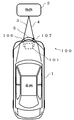
- FIG. 3 is a diagram illustrating a state where an ultrasonic transmission / reception unit of the object detection device according to Embodiment 1 of the present invention transmits / receives ultrasonic waves.
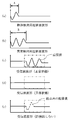
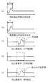
- FIG. 3 is a diagram illustrating a specific example of a transmission wave waveform and a reception wave waveform according to Embodiment 1 of the present invention. It is a figure which shows the example (comparative example) of the transmission wave waveform and the reception wave waveform at the time of using the same ultrasonic wave for the object detection ultrasonic wave and the abnormality detection ultrasonic wave.
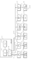
- FIG. 2 is a diagram illustrating a hardware configuration of the object detection device according to the first embodiment of the present invention.
- FIG. 3 is a diagram illustrating a configuration of a control device of the object detection device according to the first embodiment of the present invention.
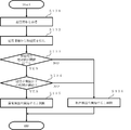
- 5 is a flowchart of an abnormality detection process and an object detection process of the object detection device according to the first embodiment of the present invention.
- FIG. 3 is a diagram showing an example of a waveform of an abnormality detecting ultrasonic wave according to Embodiment 1 of the present invention.
- 5 is a flowchart of a process for determining the start of abnormality detection of the object detection device according to the first embodiment of the present invention.
- 13 is a flowchart of a process for determining the start of abnormality detection of the object detection device according to the second embodiment of the present invention.
- FIG. 15 is a flowchart illustrating a part of the abnormality detection processing of the object detection device according to the fourth embodiment of the present invention.
- FIG. 14 is a diagram illustrating a hardware configuration of an object detection device according to a fourth embodiment of the present invention.
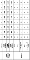
- FIG. 13 is a diagram illustrating a relationship between a result of an abnormality detection process in the object detection device according to the fourth embodiment of the present invention and an abnormal portion.
- 15 is a flowchart illustrating a part of the abnormality detection processing of the object detection device according to Embodiment 5 of the present invention.
- FIG. 15 is a diagram illustrating a relationship between a result of an abnormality detection process and an abnormal portion in the object detection device according to the fifth embodiment of the present invention.
- Embodiment 1 Hereinafter, the first embodiment of the present invention will be described with reference to FIGS. First, an outline of object detection and an outline of abnormality detection of an ultrasonic transmission / reception unit will be described using an example of a vehicle 1 (FIG. 1) including the object detection device 100 according to Embodiment 1 of the present invention. Thereafter, the configuration, operation, and effects of the first embodiment will be described in the order of the object detection device 100.
- FIG. 1 shows an example of a vehicle 1 provided with an object detection device 100 including an ultrasonic transmission / reception unit including an ultrasonic transmitter 106 and an ultrasonic receiver 107, and a control device 101 for controlling the ultrasonic transmission / reception unit.
- the figure shows how the ultrasonic transmitter 106 and the ultrasonic receiver 107 transmit and receive ultrasonic waves.
- the ultrasonic transmission / reception unit is provided on the outer surface of the vehicle 1.
- the control device 101 is provided inside the vehicle 1 and includes an ECU (Electronic Control Unit) communicably connected to the ultrasonic transmission / reception unit.
- ECU Electronic Control Unit
- the control device 101 causes the ultrasonic transmitter 106 to transmit ultrasonic waves, and determines whether the ultrasonic waves received by the ultrasonic receiver 107 include the ultrasonic waves transmitted from the ultrasonic transmitter 106. In addition, the detection of the object 2 around the vehicle 1 and the detection of the abnormality of the ultrasonic transmission / reception unit are performed.
- the detection of objects around the vehicle 1 is performed to avoid collision during driving by the user of the vehicle 1 or during automatic driving.
- the object detection device 100 calculates the presence or absence of the object 2 around the vehicle 1 and calculates the distance to the object 2 in order to avoid the collision of the vehicle 1.
- control device 101 causes ultrasonic transmitter 106 to transmit transmission wave 3 which is an ultrasonic wave transmitted from ultrasonic transmitter 106 to the vicinity of vehicle 1.
- transmission wave 3 which is an ultrasonic wave transmitted from ultrasonic transmitter 106 to the vicinity of vehicle 1.
- the transmission wave 3 transmitted from the ultrasonic transmitter 106 is reflected on the object 2 and returns to the vehicle 1 as a reflected wave 4.
- the reflected wave 4 is received by the ultrasonic receiver 107 and detected by the control device 101.
- the control device 101 determines that the ultrasonic receiver 107 is receiving the reflected wave 4
- the control device 101 detects that the object 2 is present around the vehicle 1.
- the distance to the object 2 is calculated using the elapsed time, which is the time difference between the transmission of the transmission wave 3 and the reception of the reflection wave 4, and the sound speed.
- the object detection device 100 performs object detection in the vicinity of the vehicle 1 as described above. Send to device. Note that the sound speed at the average temperature in the environment where the vehicle 1 is used is used as
- the ultrasonic transmission / reception unit Since the ultrasonic transmission / reception unit is provided on the outer surface of the vehicle 1, dirt that hinders transmission / reception of ultrasonic waves, such as mud, snow, ice, or water droplets, adheres. When the dirt adheres, the transmission intensity of the ultrasonic wave decreases, the reception sensitivity decreases, and the transmission / reception function of the ultrasonic transmission / reception unit decreases. In addition, the function of the ultrasonic transmission / reception unit deteriorates due to aging or external impact. A decrease in the transmission / reception function of the ultrasonic transmission / reception unit as described above is referred to as abnormal, and a reduced state is referred to as an abnormal state. Further, a state in which the transmission strength or the reception sensitivity becomes zero is referred to as a failure, and a state in which the transmission strength or the reception sensitivity becomes zero is referred to as a failure state. The failure state is also included in the abnormal state.
- the abnormality detection of the ultrasonic transmission / reception unit is performed in order to appropriately confirm whether the ultrasonic transmission / reception unit for detecting an object is in the abnormal state.
- the object detection device 100 determines whether or not the transmission wave 3 transmitted by the ultrasonic transmitter 106 is received by the ultrasonic receiver 107 in order to detect an abnormality of the ultrasonic transmission / reception unit.
- control device 101 first causes ultrasonic transmitter 106 to transmit transmission wave 3. As shown in FIG. 1, the transmission wave 3 directly reaches the ultrasonic receiver 107, is received as the direct wave 5, and is detected by the control device 101. When determining that the ultrasonic receiver 107 has not received the direct wave 5, the control device 101 detects an abnormality of the ultrasonic transmitter 106 or the ultrasonic receiver 107.
- the object detection device 100 performs the abnormality detection of the ultrasonic transmission / reception unit in this way, and when the abnormality is detected, information indicating the abnormality is transmitted to the ECU that controls the warning light display of the vehicle 1, the automatic driving control device, or the collision avoidance device. Transmit to other control devices such as devices.
- the ultrasonic wave transmitted from the ultrasonic transmitter 106 when performing object detection is called an object detection ultrasonic wave, and the ultrasonic wave transmitted from the ultrasonic transmitter 106 when performing abnormality detection is referred to as an abnormality detection ultrasonic wave. Called sound waves.
- FIGS. 2 and 3 show examples of the waveform of the transmission wave 3 transmitted from the ultrasonic transmitter 106 and the waveform of the reception wave that is the ultrasonic wave received by the ultrasonic receiver 107, respectively.
- An example using the object detection device 100 according to the first embodiment and a comparative example are shown.
- FIG. 2 shows a waveform when an ultrasonic wave having a longer transmission time than the object detecting ultrasonic wave is used as the abnormality detecting ultrasonic wave.
- FIG. 3 shows a waveform when the ultrasonic wave for the same transmission time as the ultrasonic wave for object detection is used as the ultrasonic wave for abnormality detection.
- the reception when the ultrasonic transmission / reception unit functions normally and receives the direct wave 5 is performed.
- the waveform of the wave ((c) in FIG. 2) and the waveform of the received wave when the ultrasonic wave (indicated by a dotted line) of another vehicle, which is an example of noise, is received without receiving the direct wave 5 (FIG. 2 (e)) can be easily distinguished.
- the ultrasonic wave for abnormality detection having the same transmission time as the ultrasonic wave for object detection is used, the ultrasonic wave transmitting / receiving section functions normally and the received wave when the direct wave 5 is received is received.
- the ultrasonic transmitter 106 transmits an ultrasonic wave for each of the object detection processing and the abnormality detection processing.
- the object detection process and the abnormality detection process are processes for detecting the reflected wave 4 and the direct wave 5 once.
- One ultrasonic wave refers to an ultrasonic wave transmitted for each object detection processing and abnormality detection processing. Also, when referring to the length of transmission time of an ultrasonic wave, it refers to the length of transmission time of this one ultrasonic wave.
- the length of the transmission time of one ultrasonic wave is determined from the time when the ultrasonic transmitter 106 starts the vibration for transmitting the ultrasonic wave in one object detection processing or the abnormality detection processing to the time when the vibration is ended ( It indicates the length of time from the start point to the end point of the transmitted ultrasonic waveform.
- the ultrasonic wave may be interrupted, but the time point at which the ultrasonic wave is interrupted is not the end time.
- the ultrasonic transmitter 106 starts the vibration for transmitting the ultrasonic wave to the last time when the vibration ends, and the transmission time is defined as the transmission time.
- FIGS. 2 and 3A and 3B show a time A indicating a transmission time of an ultrasonic wave used for object detection and a time B indicating a transmission time of an ultrasonic wave used for abnormality detection.
- the transmission time B of the abnormality detection ultrasonic wave is longer than the transmission time A of the object detection ultrasonic wave.
- the transmission time B of the abnormality detection ultrasonic wave is equal to the transmission time A of the object detection ultrasonic wave.
- each graph corresponds to the amplitude of ultrasonic waves
- the horizontal axis corresponds to time.
- the graphs of FIGS. 2 and 3A show the waveforms of the object detecting ultrasonic waves, respectively.
- the graphs in (b) respectively show the waveforms of the ultrasonic waves for abnormality detection.
- the object detection ultrasonic waves are the same, but as shown in the graph of FIG. Is longer in the first embodiment shown in FIG. Specifically, as shown in the graphs of FIGS.
- the object detection device 100 is more abnormal than the object detection ultrasonic wave as the abnormality detection ultrasonic wave.
- Use an ultrasonic wave with a long transmission time transmission time A ⁇ transmission time B).
- the object detection ultrasonic wave is an ultrasonic wave for one wave (for one cycle)
- the abnormality detection ultrasonic wave is an ultrasonic wave for two waves (for two cycles).
- Each has the same frequency.
- the graphs of FIG. 2 and FIG. 3C respectively show the waveforms of the received waves when the ultrasonic transmission / reception unit is in a normal state and the direct waves 5 corresponding to the abnormality detection ultrasonic waves can be received.
- the received wave received by ultrasonic receiver 107 is long, and in the comparative example of FIG. 3, the received wave is short.
- the graphs in (d) of FIGS. 2 and 3 show waveforms when the ultrasonic transmission / reception unit is in an abnormal state and the direct wave 5 corresponding to the ultrasonic wave for abnormality detection cannot be received.
- the signal does not include the waveform of the direct wave 5 and is a constant signal.
- the period surrounded by the dashed line is a period during which the direct wave 5 is scheduled to be received, and during this period, the ultrasonic wave receiver 107 uses the ultrasonic receiver 107 to determine the waveform of the ultrasonic wave for abnormality detection. It is determined whether an ultrasonic wave having a corresponding waveform has been received, and the direct wave 5 is detected.
- the distance between the ultrasonic transmitter 106 and the ultrasonic receiver 107 is determined when the vehicle 1 is designed, and the distance and the speed of sound are used to determine the period during which the direct wave 5 is scheduled to be received. Can be. In the graphs of FIG. 2 and FIG.
- the waveform of the direct wave 5 corresponding to the waveform of the ultrasonic wave for abnormality detection appears during the period surrounded by the dashed line, and the ultrasonic transmitter 106 operates normally. It is determined that the ultrasonic receiver 107 is receiving ultrasonic waves normally.
- the waveform of the direct wave 5 corresponding to the waveform of the abnormality detection ultrasonic wave does not appear in the period surrounded by the dashed line, and the ultrasonic transmitter 106 It can be determined that the ultrasonic wave has not been transmitted normally or that the ultrasonic receiver 107 has not normally received the ultrasonic wave.
- the ultrasonic wave transmitted by the other vehicle is an ultrasonic wave having a short transmission time of about one to several waves, like the ultrasonic wave for object detection (one wave in FIGS. 2 and 3).
- the reason is as follows.
- the direct wave 5 passing through the shortest distance from the ultrasonic transmitter 106 to the ultrasonic receiver 107 is received by the ultrasonic receiver 107.
- the reflected wave 4 reflected on the object 2 around the vehicle 1 is received by the ultrasonic receiver 107.
- the presence / absence of the object 2 is detected from the presence / absence of the reflected wave 4 and the elapsed time until reception, and the distance is calculated.
- the reflected wave 4 is important, but detection of the reflected wave 4 is not easy in a portion of the waveform of the received wave where the reflected wave 4 and the direct wave 5 overlap. Therefore, by shortening the transmission time of the ultrasonic wave for object detection, the waveform of the received direct wave 5 is shortened as much as possible, and the period in which the direct wave 5 and the reflected wave 4 overlap with each other is shortened.
- the reflected wave 4 can be detected even when the object 2 exists at a distance. For example, when the vehicle 1 is parked, it is necessary to detect an object 2 such as a vehicle or a wall at a short distance, and warn the user.
- the object detection ultrasonic wave must be an ultrasonic wave having a short transmission time. For the above reason, the vehicle 1 and the other vehicles equipped with the object detection device 100 according to the first embodiment must use ultrasonic waves having a short transmission time for object detection.
- the transmission time of the abnormality detection ultrasonic wave is longer than that of the object detection ultrasonic wave (transmission time A ⁇ transmission time B). For this reason, as shown in the graph of FIG. 2E, even if the ultrasonic wave of a short transmission time of another vehicle is received during the period of receiving the direct wave 5, the ultrasonic wave of the other vehicle is not directly transmitted.
- the object detection device 100 uses the ultrasonic wave having a longer transmission time than the object detection ultrasonic wave as the abnormality detection ultrasonic wave, and can improve the accuracy of abnormality detection. it can.
- the ultrasonic transmission / reception unit is in a failure state.
- the ultrasonic transmission / reception unit is not in a failure state but in an abnormal state (when a weak direct wave 5 is received). ), It is possible to improve the accuracy of abnormality detection without erroneously detecting the ultrasonic waves of other vehicles as the direct waves 5.
- the ultrasonic receiver 107 is receiving the weak direct wave 5 (when the waveform of the weak direct wave 5 appears in the graphs of FIGS. 2 and 3D)
- Since the direct wave 5 does not reach the appropriate intensity, it can be determined that the ultrasonic transmitter 106 does not normally transmit the ultrasonic wave or the ultrasonic receiver 107 does not normally receive the ultrasonic wave.
- the ultrasonic wave of another vehicle is received, it is difficult to distinguish whether the direct wave 5 or the ultrasonic wave of another vehicle is received in the comparative example, as described above.
- the ultrasonic wave of the other vehicle is shorter than the direct wave 5, Is easy.
- the object detection device 100 includes a control device 101, a transmission amplifier 105, an ultrasonic transmitter 106, an ultrasonic receiver 107, a reception amplifier 108, a vehicle speed sensor 109, a vehicle speed ECU 110, a bus 111, and a signal line 112.
- the vehicle includes an in-vehicle camera 113, a camera control ECU 114, a GPS (Global Positioning System) positioning sensor 115, a positioning ECU 116, a communication ECU 117, and a radio transceiver 118.
- the control device 101 is connected to a vehicle speed ECU 110, a camera control ECU 114, a positioning ECU 116, and a communication ECU 117 via a bus 111.
- the control device 101 is connected to the transmission amplifier 105 and the reception amplifier 108 via the signal line 112. Further, the transmission amplifier 105 and the ultrasonic transmitter 106, the reception amplifier 108 and the ultrasonic receiver 107, and the vehicle speed ECU 110 and the vehicle speed sensor 109 are connected via signal lines 112, respectively.
- the camera control ECU 114 and the on-vehicle camera 113, the positioning ECU 116 and the GPS positioning sensor 115, and the communication ECU 117 and the radio transceiver 118 are connected via signal lines 112, respectively.
- the vehicle-mounted camera 113, the camera control ECU 114, the GPS positioning sensor 115, the positioning ECU 116, the communication ECU 117, and the radio transceiver 118 are not essential to the first embodiment.
- the GPS positioning sensor 115, the positioning ECU 116, the communication ECU 117, and the radio transceiver 118 will be described in detail in a third embodiment.
- the control device 101 is an ECU, includes a CPU (Central Processing Unit) 102, a memory 103, and an interface 104, generates an input signal for causing the ultrasonic transmitter 106 to transmit an ultrasonic wave, and receives an ultrasonic wave. An output signal generated by the device 107 is received, and an object detection process and an abnormality detection process are performed.
- a CPU Central Processing Unit
- the CPU 102 reads the program stored in the memory 103 and executes the program.
- the CPU 102 performs the abnormality detection processing and the object detection processing.
- the program executed by the CPU 102 is stored in the memory 103.
- the memory 103 includes a RAM (Random Access Memory) for storing temporary data when the CPU 102 executes a program, and a ROM (Read Only Memory) for storing a program executed by the CPU 102 and a threshold.
- the RAM temporarily stores the output signal of the ultrasonic receiver 107 transmitted by the reception amplifier 108 and the vehicle speed ECU 110 and speed information indicating the speed of the vehicle 1.
- the interface 104 transmits and receives signals when performing the abnormality detection processing and the object detection processing.
- the interface 104 transmits a signal generated by the CPU 102 to the transmission amplifier 105. Further, it receives signals transmitted by the reception amplifier 108, the vehicle speed ECU 110, the camera control ECU 114, the positioning ECU 116, and the communication ECU 117 connected to the control device 101.
- the interface 104 includes an analog / digital converter and a digital / analog converter, and converts a digital signal generated by the CPU 102 and transmitted to the transmission amplifier into an analog signal, and the analog signal transmitted from the reception amplifier 108. To a digital signal.
- a transmission amplifier 105 and an ultrasonic transmitter 106 which are components for transmitting an ultrasonic wave corresponding to an input signal generated by the control device 101, will be described.
- the transmission amplifier 105 is connected to the control device 101 via a signal line 112, and is connected to an ultrasonic transmitter 106 so that a signal can be transmitted via the signal line 112.
- the transmission amplifier 105 amplifies the input signal transmitted from the control device 101 and transmits the amplified signal to the ultrasonic transmitter 106.
- the ultrasonic transmitter 106 is connected to the transmission amplifier 105 via the signal line 112, and includes a vibrator that vibrates in accordance with the waveform of the input signal transmitted from the transmission amplifier 105.
- the ultrasonic transmitter 106 transmits an ultrasonic wave by vibrating a medium such as air around the vibrator when the vibrator vibrates.
- the ultrasonic receiver 107 includes a vibrator that vibrates in accordance with the vibration corresponding to the frequency of the ultrasonic wave (for example, 18 kHz or more or 20 kHz or more) among the vibrations of the surrounding medium such as air.
- the ultrasonic receiver 107 is connected to the receiving amplifier 108 so as to be able to transmit a signal via the signal line 112, generates an output signal corresponding to the vibration of the transducer, and transmits the output signal to the receiving amplifier 108.
- the receiving amplifier 108 is connected to the control device 101 via the signal line 112 and is connected to the ultrasonic receiver 107 via the signal line 112, and outputs an output signal transmitted from the ultrasonic receiver 107.
- the signal is amplified and transmitted to the control device 101.
- the vehicle speed sensor 109 and the vehicle speed ECU 110 that measure and transmit the speed of the vehicle 1 and that are used by the control device 101 to determine whether to start the object detection process or the abnormality detection process will be described.
- the vehicle speed sensor 109 generates a pulse signal in proportion to the rotation speed of the driving wheels of the vehicle 1.
- the vehicle speed sensor 109 is connected to the vehicle speed ECU 110 via a signal line 112, and transmits the pulse signal to the vehicle speed ECU 110.
- the vehicle speed ECU 110 calculates the speed of the vehicle 1 according to the number of pulse signals transmitted from the vehicle speed sensor 109, and transmits speed information indicating the speed of the vehicle 1 to the control device 101 via the bus 111. Transmission of speed information is performed at regular intervals.
- the bus 111 is a communication line that connects the control device 101 and each ECU, and transmits signals transmitted and received between these ECUs.
- the bus 111 forms an in-vehicle network, in which a CAN frame specified by a CAN (Control Area Network) protocol is transmitted and received.
- the signal line 112 is a communication line that connects devices such as the ultrasonic transmitter 106 that does not belong to the in-vehicle network constituted by the bus 111 and transmits signals transmitted and received between the devices.
- the determination unit 121 has a function of determining whether to start the object detection process or the abnormality detection process based on speed information indicating the speed of the vehicle 1 received from the vehicle speed ECU 110 via the interface 104.
- the object detection unit 122 has a function of generating an input signal for causing the ultrasonic transmitter 106 to transmit the object detection ultrasonic wave based on the judgment result of the judgment unit 121 that the object detection process is started.
- the object detection unit 122 reflects the object detection ultrasonic wave from the output signal transmitted from the reception amplifier 108 via the reception unit 125 described later to the object 2 around the vehicle 1 to generate a reflected wave 4. It has a function of acquiring an output signal during a period of being received by the ultrasonic receiver 107, determining whether or not the output signal includes a signal of the reflected wave 4, and detecting the object 2.
- the abnormality detection unit 123 has a function of generating an input signal for causing the ultrasonic transmitter 106 to transmit ultrasonic waves for abnormality detection based on the determination result of the determination unit 121 that the abnormality detection processing is started. Further, the abnormality detection unit 123 outputs an output signal during a period when the ultrasonic wave for abnormality detection is received by the ultrasonic receiver 107 as the direct wave 5 among output signals transmitted from the reception amplifier 108 via the reception unit 125 described later. It has a function of acquiring a signal (hereinafter, referred to as an abnormality detection output signal), determining whether or not the output of the abnormality detection signal includes the signal of the direct wave 5, and detecting an abnormality of the ultrasonic transmission / reception unit.
- an abnormality detection output signal a signal (hereinafter, referred to as an abnormality detection output signal)
- the transmission unit 124 has a function of converting a digital signal, which is an input signal generated by the object detection unit 122 and the abnormality detection unit 123, into an analog signal and transmitting the analog signal to the transmission amplifier 105 via the signal line 112.
- the receiving unit 125 receives an analog signal, which is an output signal generated by receiving the ultrasonic wave by the ultrasonic receiver 107, from the receiving amplifier 108 via the signal line 112, converts the analog signal into a digital signal, and converts the analog signal into an object signal. And a function of outputting to the abnormality detection unit 123.
- the determination unit 121, the object detection unit 122, and the abnormality detection unit 123 are realized by the CPU 102 executing a program for exhibiting the function of each unit.
- the transmitting unit 124 and the receiving unit 125 are configured by the interface 104.
- the configuration of the object detection device 100 has been described.
- the operation of the object detection device 100 will be described.
- the operation in the abnormality detection processing and the object detection processing of the object detection device 100 will be described, and then the operation in the processing for determining the start of abnormality detection will be described.
- the operations in the abnormality detection processing and the object detection processing of the object detection device 100 are performed according to the flowchart in FIG.
- the abnormality detection process of the object detection device 100 is performed by the abnormality detection unit 123 of the control device 101, and the object detection process is performed by the object detection unit 122 of the control device 101.
- the abnormality detection processing and the object detection processing are started when the power of the vehicle 1 is turned on. Specifically, when the power of the vehicle 1 is turned on, the CPU 102 of the control device 101 reads a program for performing the abnormality detection process and the object detection process from the memory 103, and starts a process based on the program. The CPU 102 executes a process of determining the start of abnormality detection, and determines whether to start abnormality detection or object detection (step S101). The details of the process for determining the start of abnormality detection will be described later.
- step S101 When determining that abnormality detection is to be started (YES in step S101), the CPU 102 generates an input signal for causing the ultrasonic transmitter 106 to transmit ultrasonic waves for abnormality detection, and transmits the input signal from the interface 104 (transmission unit 124). The data is transmitted to the transmission amplifier 105 (step S102). Specifically, the CPU 102 reads out the transmission time and signal waveform of the ultrasonic wave for abnormality detection stored in the memory 103 in advance, and generates a digital signal that is an input signal having a length corresponding to the transmission time.
- the interface 104 converts the generated digital signal into an analog signal using a built-in digital / analog converter, and transmits the analog signal to the transmission amplifier 105. Further, the CPU 102 stores the waveform of the input signal in the memory 103. Here, the transmission time of the ultrasonic wave for abnormality detection stored in the memory 103 is set longer than the transmission time of the ultrasonic wave for object detection.
- the CPU 102 obtains an output signal (output signal for abnormality detection) of the ultrasonic receiver 107 during a period when the ultrasonic wave for abnormality detection is received by the ultrasonic receiver 107 as the direct wave 5 (step S103). Specifically, the ultrasonic receiver 107 generates an output signal and transmits it to the receiving amplifier 108 as needed. After that, the output signal is amplified by the receiving amplifier 108 and transmitted to the interface 104. The interface 104 converts an output signal, which is an analog signal, into a digital signal using a built-in analog / digital converter. The CPU 102 stores the output signal converted into the digital signal in the memory 103.
- the CPU 102 reads an output signal (output signal for abnormality detection) after a predetermined time has elapsed from the transmission time of the input signal, among the output signals stored in sequence.
- the predetermined time is a direct wave propagation time that is a time from when the ultrasonic transmitter 106 starts transmitting the ultrasonic wave for abnormality detection to when the ultrasonic receiver 107 starts receiving the direct wave 5.
- This is a time obtained by adding an internal processing time, which is a time required for internal processing such as generation, transmission and reception of a signal in the object detection device 100, and storage and readout processing to and from the memory 103.
- the length of the direct wave 5 matches the length of the abnormality detection ultrasonic wave
- the length (period) of the abnormality detection output signal to be read is determined by the transmission of the abnormality detection ultrasonic wave after a predetermined time has elapsed. Until the time corresponding to the time elapses.
- the input signal is s (t)
- the output signal is r (t) (t is time, the transmission start time of the input signal s (t) is zero)
- the predetermined time is ⁇ .
- the output signal r (t) read from the memory 103 is not from r (0) which is a signal at the same time as s (0), but after r ( ⁇ 1 ) after a predetermined time ⁇ 1 has elapsed. Signal.
- the CPU 102 obtains a correlation value between the generated input signal and the output signal for abnormality detection (step S104).
- the correlation value R s, r ( ⁇ 1 ) between the input signal s (t) and the output signal r (t) is obtained by the following equation.
- ⁇ 1 is the time from the starting point of the waveform of the input signal to the starting point of the waveform of the output signal for abnormality detection, and matches the predetermined time used in step S103.
- the input signal s (t) at the time t and the predetermined time ⁇ 1 elapse from the time t, and the direct wave 5 Find the product of r (t + ⁇ 1 ) at the time of reception.
- the integral interval is from time zero to the time T 1 that passes the transmission time of the abnormality detection ultrasound. That is, the integration section is set to a section that matches the length of the transmission time of the abnormality detection ultrasonic wave. This also corresponds to the length of the direct wave 5.
- Describing step S104 specifically, the CPU 102 first reads an input signal from the memory 103.
- the CPU 102 obtains the product of the amplitudes of the input signal and the start points of the abnormality detection output signal acquired in step S103, and obtains the product of the amplitudes up to the end point following the calculation of the start points (s (t in the above equation). ) And r (t + ⁇ 1 )). Then, the CPU 102 sums up the products of the obtained amplitude values to obtain a correlation value.
- the CPU 102 reads the first threshold value from the memory 103, and determines whether the correlation value is equal to or less than the first threshold value (Step S105).
- the first threshold is a threshold for determining whether the output signal includes the waveform of the direct wave 5. If the first threshold value is set to a large value, it is possible to detect a minor abnormality of the ultrasonic transmission / reception unit, that is, an abnormality that is not a failure. If set to a small value, a severe abnormality, that is, a failure can be detected, but it is necessary that the value be a certain value or more in order to prevent false detection of an ultrasonic wave of another vehicle, which is an example of noise, as a direct wave. .
- a value greater than or equal to the correlation value between the input signal of the ultrasonic wave for abnormality detection and the output signal when the ultrasonic wave of another vehicle is received is used. More specifically, the length of the transmission time of the ultrasonic wave of the other vehicle is the same as that of the ultrasonic wave for object detection of the first embodiment, so that the reflected wave 4 of the reflected wave 4 is detected in the object detection processing of the first embodiment.
- a value greater than or equal to a sixth threshold (described later), which is a threshold for determining the presence or absence, is used.
- the CPU 102 determines that the correlation value is equal to or smaller than the first threshold (YES in step S105)
- the CPU 102 detects an abnormality in the ultrasonic transmission / reception unit. Then, the CPU 102 generates a signal indicating that the abnormality has been detected, and transmits the signal from the interface 104 to another control device connected to the in-vehicle network (step S106).
- step S105 After the CPU 102 determines that the correlation value is not less than or equal to the first threshold value (NO in step S105), and generates and transmits a signal indicating that the CPU 102 has detected an abnormality (step S106), the CPU 102 again performs Then, a process for determining the start of abnormality detection is performed, and this flow is repeated.
- step S107 to step S111 the flow of the object detection process (from step S107 to step S111) when it is determined that the object detection is to be started in the process of determining the start of abnormality detection (NO in step S101) will be described.
- the processing from step S107 to step S111 in the object detection processing is the same as the processing from step S102 to step S106 in the above-described abnormality detection processing, except for a part, and hereinafter, different points will be mainly described. .
- the CPU 102 generates an input signal for transmitting the object detection ultrasonic wave (step S107, corresponding to step S102 of the abnormality detection process).
- the transmission time of the object detection ultrasonic wave is shorter than the transmission time of the abnormality detection ultrasonic wave.
- the CPU 102 acquires an output signal from the ultrasonic receiver 107 during the period of receiving the reflected wave 4 in order to detect the presence or absence of the waveform of the reflected wave 4 (Step S108, Step S103 of the abnormality detection processing). And corresponding).
- the period for receiving the reflected wave 4 is different from the period for receiving the direct wave 5 (step S103), and is a period after the period for receiving the direct wave 5.
- the output signal obtained by the CPU 102 includes, from the transmission time of the input signal, the direct wave propagation time, the time during which the waveform of the direct wave 5 appears (coincides with the transmission time of the ultrasonic wave for object detection), and the internal signal. This is an output signal after the processing time has elapsed.
- the output signal during the period of receiving the reflected wave 4 is an output signal after the point at which the waveform of the direct wave 5 disappears from the output signal.
- the above time point is determined as follows.
- the above time point is a time point at which the starting point of the waveform of the reflected wave 4 reflected from the object 2 located at the shortest distance in the range where the object detection device 100 can detect the object appears. Therefore, the shortest reflected wave propagation time, which is the time required from the transmission of the transmission wave 3 to the reception of the reflected wave 4, is obtained from the shortest distance and sound speed determined at the time of design that can detect the object.
- the above point is determined by adding the internal processing time to the time.
- the length (period) of the output signal read out by the CPU 102 is at least the transmission time of the ultrasonic wave for object detection from the above time point.
- the output signal is obtained over a wider range according to the range in which the object detection is performed, until the time that elapses matches.
- the range of the output signal to be acquired is determined so that the end point of the waveform of the reflected wave 4 reflected from the object 2 located at the longest distance is included in the range in which the object can be detected.
- the longest reflected wave propagation time which is the time required from the transmission of the transmission wave 3 to the reception of the reflected wave 4, is determined from the longest detectable object distance and the sound speed determined at the time of design.
- the acquisition range (end point) of the output signal is determined. Therefore, the output signal obtained by the CPU 102 is an output signal from the time after the input signal is transmitted to the time determined based on the shortest distance for object detection elapses until the time determined based on the longest distance for object detection elapses. Becomes
- the CPU 102 obtains a correlation value between the generated input signal and the output signal and a cross-correlation function that is a set thereof (step S109, corresponding to step S104 of the abnormality detection process).
- the equation for obtaining the correlation value is as follows, and ⁇ and the integration interval are different from the above equation (1) used in the abnormality detection processing.
- ⁇ 1 used in the abnormality detection processing is a time from the start point of the waveform of the input signal to the start point of the waveform of the output signal for abnormality detection, and is a fixed value based on the distance between the ultrasonic transmitter 106 and the ultrasonic receiver 107.
- ⁇ used in the object detection processing is a variable. When obtaining a correlation value in the object detection processing, ⁇ is changed, and a correlation value that is an integral value of a product of the input signal s (t) and the output signal r (t + ⁇ ) is sequentially calculated.
- the minimum value of ⁇ which is a variable, is the sum of the shortest reflected wave propagation time and the internal processing time. In other words, it is the sum of the direct wave propagation time, the time during which the waveform of the direct wave appears (coincides with the transmission time of the ultrasonic wave for object detection), and the internal processing time.
- the maximum value is the sum of the longest reflected wave propagation time and the internal processing time.
- a set of correlation values sequentially obtained by changing ⁇ as described above is defined as a cross-correlation function. For integration interval is from time zero to time T 2, which has elapsed transmission time ultrasonic object detection. Since the object detecting ultrasonic short transmission time than ultrasonic anomaly detection, T 2 is the T 1 value smaller than that used by the abnormality detection processing (T 1> T 2).
- the CPU 102 determines whether or not there is a peak whose peak height (magnitude of the correlation value) is equal to or larger than the sixth threshold value in the waveform of the cross-correlation function obtained in step S109 (step S110, the abnormality detection process).
- the sixth threshold is a threshold stored in the memory 103, and is a threshold for determining whether the output signal includes the waveform of the reflected wave 4. If the sixth threshold is set to a large value, it is possible to prevent erroneous detection due to noise when detecting the object 2 around the vehicle 1. If a small value is set, a small object 2, an object 2 having a low reflectance, or a distant object 2 can be detected.
- the ultrasonic transmitter 106 transmits the object detection ultrasonic wave from the ⁇ corresponding to the peak of the cross-correlation function, and the ultrasonic receiver The elapsed time required for 107 to receive the reflected wave 4 is obtained, and the distance to the object 2 is calculated from the elapsed time and the sound speed. Then, the CPU 102 generates a signal indicating that the object 2 has been detected and the distance to the object 2, and transmits the signal to another control device connected to the vehicle-mounted network (step S111, step S106 of the abnormality detection process). Correspondence).
- ⁇ corresponding to the peak is a value that matches the time from the start point of the input signal to the start point of the waveform of the reflected wave 4, the above-described elapsed time is calculated by subtracting the internal processing time from ⁇ . can do.
- step S110 After determining that there is no peak (NO in step S110), and after generating and transmitting a signal indicating that the object 2 has been detected (step S111), the CPU 102 ends the object detection process, and again Then, the processing of this flow is repeated.
- An example of the transmission time length of the object detection ultrasonic wave and the abnormality detection ultrasonic wave is shown.
- the ultrasonic wave for object detection an ultrasonic wave composed of one to several waves is used. In the description using FIG. 2, an example for one wave is shown.
- an example using an ultrasonic wave composed of four waves is shown.
- the transmission time is 0.1 ms.
- an ultrasonic wave having a longer transmission time than the ultrasonic wave for object detection is used as the ultrasonic wave for abnormality detection.
- FIG. 1 An ultrasonic wave having a longer transmission time than the ultrasonic wave for object detection is used as the ultrasonic wave for abnormality detection.
- the ultrasonic wave for object detection is one wave and the ultrasonic wave for abnormality detection is two waves.
- the transmission time is 100.8 ms, and the ultrasonic wave for object detection is transmitted.
- the transmission time is about 1000 times as long as (the four waves).
- an ultrasonic wave having a larger sum of absolute values of the amplitude than the object detection ultrasonic wave is used as the abnormality detection ultrasonic wave.
- the correlation value when the direct wave 5 can be received can be increased, and the S / N ratio can be increased.
- the input signal generated in the abnormality detection processing may be a signal obtained by modulating the reference signal by the CPU 102 and adding a code.
- the ultrasonic transmitter 106 transmits an abnormality detecting ultrasonic wave with a code.
- the CPU 102 reads the waveform of the reference signal (carrier) and the waveform of the modulation signal stored in the memory 103 and multiplies them to generate an input signal with a code.
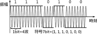
- FIG. 7 is an example (28 waves) of an input signal obtained by phase-modulating a reference signal (carrier) and carrying information of a predetermined code sequence.
- the code sequence [1,1,1,0, [1,0,0].
- FIG. 7 shows an example of an input signal having 7 bits and 4 bit waves.
- the number of bits indicates the length of the code sequence, and the number of bit waves indicates the number of waves used to represent one code. That is, in the above example, four waves are used to represent one code (1 or 0). Also, seven waves of four waves are prepared and used as one input signal (28 waves in total).
- a signal having 63 bits and 64 bits can be used (4032 waves in total).
- An M-code sequence, a Gold code sequence, or a Barker code sequence can be used as a coding sequence to be carried on an input signal.
- FIG. 7 shows an example of phase modulation, but amplitude modulation or frequency modulation may be performed.
- the CPU 102 multiplies the reference signal (carrier) by the modulation signal to generate an input signal.
- a modulator is connected to the CPU 102, and the modulator modulates the reference signal to generate an input signal. Is also good. In the case of the ultrasonic transmitter 106 using a piezo element, no modulation is required, and only a voltage needs to be applied to the ultrasonic transmitter 106 for a period corresponding to the transmission time.
- the process of determining the start of the abnormality detection of the object detection device 100 is performed by the determination unit 121 of the control device 101.
- the control device 101 receives the speed information transmitted from the vehicle speed ECU 110 through the interface 104 and sequentially stores the speed information in the memory 103.
- the determination unit 121 uses the plurality of pieces of speed information to determine whether to start abnormality determination. A determination is made as to whether or not it is. Note that each speed information includes the measurement time in addition to the speed of the vehicle 1.
- step S101 (FIG. 6)
- the CPU 102 acquires the latest speed information and the speed information up to a time that has been traced back for a predetermined time (step S131). Specifically, the CPU 102 designates an address in the memory 103 where the speed information is stored until the measurement time reaches a predetermined time, and outputs the speed information stored in the address specified in the memory 103. To read the speed information.
- the CPU 102 calculates the acceleration of the vehicle 1 at each measurement time from the plurality of pieces of read speed information (Step S132).
- the CPU 102 reads the third threshold value from the memory 103, and determines whether or not the absolute values of all the calculated accelerations are equal to or less than the third threshold value which is a predetermined threshold value (step S133).
- the third threshold is a threshold for determining whether the stop of the vehicle 1 is an emergency stop, and is a value to be compared with the absolute value of the acceleration. When the absolute value of the acceleration is larger than the third threshold value, it is determined that the stop is highly urgent, and when it is smaller, it is determined that the stop is less urgent.
- the CPU 102 determines that the speed of the vehicle 1 indicated by the speed information is equal to or less than the second threshold which is a predetermined threshold. It is determined whether or not the operation is continued (step S134). Specifically, the CPU 102 reads the second threshold from the memory 103.
- the second threshold is a threshold for determining whether the vehicle 1 is in a stopped state, and is a value to be compared with the speed of the vehicle 1. For example, when it is determined that the vehicle 1 is stopped at a speed of 3 km / h or less, a value exceeding 3 km / h is used as the second threshold value.
- the CPU 102 determines whether or not the speed of the vehicle 1 at all the measurement times read in step S131 is equal to or less than the second threshold. When the speeds at all the measurement times are equal to or lower than the second threshold, the CPU 102 determines that the time during which the speed of the vehicle 1 is equal to or lower than the second threshold continues.
- step S134 If the time during which the speed is equal to or less than the second threshold value continues (YES in step S134), the CPU 102 determines that abnormality detection is to be started (step S135), and abnormality detection processing after step S102 (FIG. 6) To start.
- step S133 When all the accelerations are not equal to or less than the third threshold (NO in step S133), or when the time during which the speed is equal to or less than the second threshold does not continue (NO in step S134), the CPU 102 performs the object detection. It is determined to start (step S136), and the object detection processing after step S107 (FIG. 6) is started.
- step S134 the reason why the condition that the speed of the vehicle 1 is equal to or less than the second threshold value is continued (step S134) when the determination to start the abnormality detection is performed (step S135) will be described.
- an ultrasonic wave having a longer transmission time than the object detection ultrasonic wave is used as the abnormality detection ultrasonic wave. Therefore, the abnormality detection processing requires more time than the object detection processing because the transmission time of the ultrasonic wave is longer. Further, since different ultrasonic waves are used for object detection and abnormality detection, object detection cannot be performed while abnormality detection processing is being performed.
- the condition for starting the abnormality detection is a condition that the vehicle 1 is in a stopped state and a condition that the vehicle 1 is in a stopped state for a long time.
- the stopped state of the vehicle 1 includes not only a state where the vehicle 1 is completely stopped (a state where the speed is zero) but also a state where the vehicle 1 is slightly moving (the speed is several km / h). This is because the vehicle 1 may slightly move due to a weak brake application, and such a case is included in the stop state.
- step S133 the condition that the absolute value of the acceleration is equal to or less than the third threshold (step S133) when the determination to start the abnormality detection is performed (step S135) will be described.
- the condition for starting the abnormality detection is that the vehicle 1 is not in an emergency stop.
- step S134 in the first embodiment that the speed of the vehicle 1 is equal to or less than the second threshold is referred to as a stopping condition.
- the object detection device 100 and the control device 101 according to the first embodiment of the present invention are configured as described above, and have the following effects.
- the object detection device 100 and the control device 101 use an ultrasonic wave having a longer transmission time than the object detection ultrasonic wave as the abnormality detection ultrasonic wave.
- an ultrasonic wave having a short transmission time is used.
- the object detection device 100 and its control device 101 use an ultrasonic wave having a long transmission time as the abnormality detection ultrasonic wave, an abnormal In the detection processing, it is easy to distinguish the ultrasonic waves for abnormality detection from noises such as ultrasonic waves of other vehicles.
- the correlation value between the input signal and the output signal generated based on noise such as ultrasonic waves of another vehicle does not increase as compared with the case where the direct wave 5 can be normally received.
- the object detection device 100 and its control device 101 use an ultrasonic wave having a larger sum of absolute values of the amplitudes than the object detection ultrasonic wave as the abnormality detection ultrasonic wave.
- the magnitude of the correlation value between the input signal and the output signal is proportional to the sum of the absolute values of the amplitude of each signal. Therefore, by using an ultrasonic wave having a large sum of the absolute values of the amplitudes, the correlation value can be increased, and the S / N ratio can be increased. As a result, a large value can be used as the first threshold value, and erroneous determination can be suppressed even in an environment with large noise.
- the object detection device 100 and its control device 101 can use the ultrasonic wave with a code as the abnormality detection ultrasonic wave when performing the abnormality detection.
- a code By using an ultrasonic wave with a code, it is easy to distinguish it from noise such as ultrasonic waves without a code of another vehicle. As a result, even when noise such as ultrasonic waves of another vehicle is received during the period in which the direct wave 5 is received, it is possible to accurately detect the abnormality of the ultrasonic transmitter 106 or the ultrasonic receiver 107. It is possible.
- the object detection device 100 and the control device 101 start abnormality detection when the stop condition that the speed of the vehicle 1 is equal to or less than the second threshold is satisfied. Since the object detection device 100 and its control device 101 use an ultrasonic wave for abnormality detection having a long transmission time, the abnormality detection process takes a long time because the transmission time is long. Further, since different ultrasonic waves are used for the object detection ultrasonic wave and the abnormality detection ultrasonic wave, the object detection processing and the abnormality detection processing cannot be performed simultaneously.
- the object detection device 100 and its control device 101 start abnormality detection when the above-mentioned stop condition is satisfied, the vehicle 1 is in a stopped state, and no object detection is required, and the time of the abnormality detection process
- the abnormality detection process can be started in a situation in which is possible. Therefore, it is possible to secure the time for the abnormality detection processing when the vehicle is stopped, while performing the object detection processing when the vehicle needs to be detected.
- the object detection device 100 and its control device 101 start abnormality detection when the absolute value of the acceleration of the vehicle 1 is equal to or less than the third threshold. If the acceleration (deceleration) is large when the vehicle 1 stops, it can be determined that the vehicle 1 is in an emergency stop. The emergency stop is performed when monitoring around the vehicle 1 is to be continued. Therefore, it is better to continue detecting objects around the vehicle 1.
- the object detection device 100 and its control device 101 start abnormality detection when a gentle stop with low acceleration is performed, and continue object detection during an emergency stop. Therefore, at the time of an emergency stop, the object detection can be continued and the safety of the vehicle 1 can be improved.
- step S101 in FIG. 6 When it is determined in step S101 in FIG. 6 that abnormality detection is to be started, the object detection device 100 and the control device 101 perform abnormality detection processing thereafter (steps S102 to S106). At any time during the process of S106, the process of determining whether to start the object detection is repeated. If it is determined that the object detection is to be started, the abnormality detection process is stopped halfway and the object detection process (steps S107 to S111) May be performed. In this way, the object detection process can be started immediately when the vehicle 1 starts moving during the abnormality detection process and it is determined that the object detection is to be started in the process of determining the start of the abnormality detection.
- the object detection device 100 and its control device 101 determine in the process of determining the start of abnormality detection that the acceleration is equal to or less than the third threshold, the speed is equal to or less than the second threshold, and the speed is equal to or less than the second threshold. It is determined that abnormality detection is started on condition that time continues. It is not necessary to use all of these three conditions, and the condition may be that the acceleration is equal to or less than the third threshold and that the speed is equal to or less than the second threshold, or only that the speed is equal to or less than the second threshold. It may be a condition.
- Embodiment 2 Next, a second embodiment of the present invention will be described. A description of portions similar to those in the configuration and operation described in the first embodiment will be omitted, and portions different from the first embodiment and portions not described in the first embodiment will be described below.
- the acceleration is equal to or less than the third threshold
- the speed is equal to or less than the second threshold
- the time during which the speed is equal to or less than the second threshold continues.
- the start of abnormality detection is determined.
- the configuration of the object detection device 100 and the control device 101 of the second embodiment will be described.
- the object detection device 100 according to the second embodiment includes an in-vehicle camera 113 for photographing the front of the vehicle 1 and a camera control ECU 114 for controlling the in-vehicle camera 113 (FIGS. 4 and 5).
- the control device 101 receives, via the camera control ECU 114, image data in front of the vehicle 1 captured by the on-board camera 113, and determines whether or not the vehicle 1 remains stopped for a long time.
- the in-vehicle camera 113 is configured so that the control device 101 captures an image in front of the vehicle 1 which is information for determining whether or not the vehicle 1 is stopped for a long time.
- the on-vehicle camera 113 is installed around a windshield or a front grill in the vehicle so that an image of the front of the vehicle 1 can be taken.
- the front of the vehicle 1 is periodically photographed, and the photographed image data is transmitted to the camera control ECU 114 via the signal line 112.
- the image data includes information on the shooting time.
- the camera control ECU 114 collects image data from the onboard camera 113 and transmits the image data to the control device 101.
- the camera control ECU 114 receives image data transmitted from the vehicle-mounted camera 113 via the signal line 112, converts the image data into a CAN frame format, and transmits the CAN frame to the control device 101 via the bus 111. Further, the camera control ECU 114 controls the vehicle-mounted camera 113 by transmitting a command relating to start, stop, or change of a cycle to the vehicle-mounted camera 113.
- control device 101 for receiving the image data and determining whether or not the stop state of the vehicle 1 continues for a long time.
- image data in front of the vehicle 1 captured by the on-board camera 113 is stored for a certain period.
- the shooting time is also stored.
- An image recognition program for recognizing a specific object 2 from an image captured by the on-vehicle camera 113 is stored in the memory 103 included in the control device 101.
- the CPU 102 can read and execute the image recognition program to perform image recognition.
- the process of determining the start of abnormality detection is performed by the determination unit 121 of the control device 101.
- the processes from step S131 to step S134, the processes at step S135, and the process at step S136 are the same as those in the first embodiment (FIG. 8).
- steps S201 to S204 are further added. The processing of the added steps S201 to S204 will be described.
- step S134 it is determined that the vehicle 1 is not in an emergency stop (YES in step S133) and is in a stopped state for a long time (YES in step S134).
- the CPU 102 of the control device 101 acquires a plurality of temporally continuous image data including image data at the latest photographing time, which is image data in front of the vehicle 1 (step S201). Specifically, the CPU 102 specifies an address in the memory 103 of the image data shot after a predetermined time from the current time, outputs a command to the memory 103 to output the image data, and stores the image data in the memory 103. Read from 103.
- the CPU 102 calculates a change cycle of the stop signal from the first shooting time of the image in which the signal of the traffic light included in the image has changed to the stop signal (red signal) and the shooting time of the image in which the stop signal has changed. (Step S202). Specifically, the CPU 102 extracts a traffic signal included in each image data read from the memory 103. A well-known method such as pattern matching is used for image recognition. Further, the CPU 102 determines whether the color of the extracted signal of the traffic light is red from the luminance information and the color difference information of the image data.
- the CPU 102 sets the earliest shooting time to the stop signal and sets the latest shooting time to the stop signal in the temporally continuous images in which the color of the signal is determined to be the stop signal (red signal). As a time, a change cycle of the stop signal is calculated from a difference between these times.
- the CPU 102 determines when the current stop signal has changed to the stop signal based on the image capturing time.
- the remaining time until the current stop signal is changed is calculated using the shooting time and the change cycle (step S203). Specifically, the CPU 102 adds a change cycle to the photographing time closest to the current time among the photographing times of the images determined that the color of the signal has changed to the stop signal (red signal), and changes the current stop signal. Is obtained, and the remaining time is calculated from the difference from the current time.
- the CPU 102 determines whether or not the remaining time is equal to or greater than a seventh threshold value which is a predetermined threshold value (step S204).
- the seventh threshold is stored in the memory 103.
- the seventh threshold is a threshold for determining whether the stop state of the vehicle 1 is for a long time, and is a threshold that is compared with the remaining time until the stop signal changes. For example, when the abnormality detection process requires a time of one second, the seventh threshold value uses a value of one second or more.
- CPU 102 determines that vehicle 1 has been in a stopped state for a long time, and determines that abnormality detection is to be started (step S135). If the remaining time is not equal to or greater than the seventh threshold value (NO in step S204), CPU 102 determines that vehicle 1 is not in a long-time stop state, and determines that object detection is to be started (step S136).
- step S135 or S136 After the processing of step S135 or S136, the processing of this flow ends, and the CPU 102 performs the abnormality detection processing (steps S102 to S106) or the object detection processing (steps S107 to S111) of FIG.
- the object detection device 100 and the control device 101 according to the second embodiment of the present invention are configured as described above, and have the following effects.
- the vehicle 1 in addition to the conditions of the first embodiment, it is determined whether or not the vehicle 1 is stopped for a long time by a stop signal by using information acquired from the vehicle-mounted camera 113 that photographs the front of the vehicle 1. judge. As a result, it is possible to more accurately determine whether or not the vehicle 1 continues to be stopped for a long period of time, and to secure the time for the abnormality detection processing when the vehicle is stopped while performing the object detection processing when the vehicle needs to detect the object. Can be.
- the object detection device 100 and its control device 101 have compared the remaining time until the stop signal is changed with the seventh threshold value to determine that the vehicle 1 is to be kept in a long stop state.
- the signal included in the image data at the shooting time closest to the time is the stop signal, it may be determined that the vehicle 1 is to be kept in the long-time stopped state, and that the abnormality detection may be started.
- the object detection device 100 and the control device 101 of the first embodiment have a condition that the acceleration is equal to or less than the third threshold, the speed is equal to or less than the second threshold, and In addition to the fact that a certain time continues, whether or not the vehicle 1 has been stopped for a long time has been determined using the information in front of the vehicle 1, but without using the condition of the first embodiment, The determination may be made using only the information ahead of the vehicle 1 or may be made using a part of the conditions of the first embodiment and the information ahead of the vehicle.
- the object detection device 100 and its control device 101 not only use the image captured by the on-board camera 113 to determine that the vehicle 1 is to be kept in a long stop state by the stop signal of the traffic signal, but also It is also possible to determine that there is a traffic jam ahead and the stop state continues for a long time.
- the memory 103 stores an eighth threshold.
- the eighth threshold is a threshold for determining whether or not the vehicle 1 is stopped for a long time, and is a threshold that is compared with the number of vehicles stopped ahead.
- the CPU 102 acquires an image in front of the vehicle 1 (corresponding to step S201), recognizes a vehicle stopped in front, and obtains the number of vehicles stopped in front (referred to as stop information) (step S202 and step S202).
- the CPU 102 determines whether or not the number of vehicles stopped ahead is equal to or greater than the eighth threshold (corresponding to step S204). If the number of vehicles stopped ahead is equal to or greater than the eighth threshold, it is determined that traffic congestion has occurred, and it is determined that abnormality detection is to be started (corresponding to step S135). Determines that no congestion has occurred and determines to start object detection (corresponding to step S136).
- the change cycle of the stop signal is calculated every time the process of determining the start of the abnormality detection is performed (step S202).
- the change cycle is calculated once.
- the change cycle may be stored in the memory 103, and the remaining time may be calculated (step S203) using the change cycle stored in the memory 103 without performing the calculation process (step S202). .
- Embodiment 3 Next, a third embodiment of the present invention will be described. A description of the same parts as those in the configuration and operation of the second embodiment will be omitted, and parts different from the second embodiment will be described below. Note that Embodiment 3 can be used in combination with Embodiment 2.
- the stop state of the vehicle 1 in addition to the conditions of the first embodiment, it is determined whether or not the stop state of the vehicle 1 continues for a long time by using information acquired from the on-board camera 113 that photographs the front of the vehicle 1. Was.
- whether the stop state of the vehicle 1 is continued for a long time by using information obtained by communication with the outside of the vehicle 1 instead of the information obtained from the onboard camera 113 of the second embodiment. Is determined.
- the configuration of the object detection device 100 and the control device 101 of the third embodiment will be described.
- the object detection device 100 according to the third embodiment includes a GPS positioning sensor 115 and a positioning ECU 116 for generating position information of the vehicle 1, and a communication ECU 117 and a radio transceiver 118 for performing information communication with the outside of the vehicle 1. (FIGS. 4 and 5).
- the GPS positioning sensor 115 is installed in the vehicle 1 and receives a positioning signal from a GPS satellite.
- the positioning ECU 116 is connected to the GPS positioning sensor 115 via the signal line 112, and acquires a positioning signal received by the GPS positioning sensor 115.
- the positioning ECU 116 calculates the latitude and longitude of the vehicle 1 from the acquired positioning signal, and transmits the position information to the communication ECU 117 and the control device 101 via the bus 111 as position information.
- the communication ECU 117 acquires the position information of the vehicle 1 from the positioning ECU 116 via the bus 111. Then, the position information is added to the signal requested by the traffic information to the outside, and transmitted to the radio transceiver 118 connected via the signal line 112. Further, the communication ECU 117 transmits a signal requesting traffic information, and as a result, acquires the traffic information received by the radio transceiver 118 from the radio transceiver 118. Then, the traffic information is transmitted to the control device 101 connected via the bus 111.
- the traffic information includes position information of a plurality of traffic lights located in front of the vehicle 1 and information of time when stop signals of the plurality of traffic lights change.
- the radio wave transceiver 118 transmits a signal requested by traffic information transmitted from the communication ECU 117 to the outside by radio waves, and receives a radio wave carrying traffic information from the outside. Therefore, it is installed in the vehicle 1 at a position where radio waves can be transmitted and received, and transmits and receives radio waves of a specific frequency corresponding to a communication standard such as 5G or LTE or a frequency used in inter-vehicle communication.
- the traffic information transmitted by the communication ECU 117 and the position information of the vehicle 1 transmitted by the positioning ECU 116 are sequentially stored and updated in the memory 103 constituting the control device 101 of the third embodiment.
- the process of the control device 101 according to the third embodiment differs from the flowchart (FIG. 9) of the process of judging the start of abnormality detection in the second embodiment in steps S201, S202, and S203. These processes are performed by the determination unit 121 of the control device 101.
- the CPU 102 of the control device 101 reads the position information of the plurality of traffic signals included in the position information and the traffic information of the vehicle 1 from the memory 103, calculates the distance between the vehicle 1 and the traffic signals, and Identify nearby traffic lights. Further, the CPU 102 reads from the memory 103 the time at which the specified stop signal of the traffic light changes (corresponding to step S201 in FIG. 9). Further, the CPU 102 calculates the remaining time, which is the difference between the time when the read stop signal changes and the current time (corresponding to steps S202 and S203 in FIG. 9). The subsequent processing is the same as in the second embodiment, and it is determined whether the remaining time is equal to or greater than the seventh threshold. If the remaining time is equal to or greater than the seventh threshold, it is determined that abnormality detection is to be started. It is determined that the object detection is to be started (step S204, step S135, and step S136).
- the object detection device 100 and its control device 101 according to Embodiment 3 of the present invention are configured as described above, and have the following effects.
- the third embodiment in addition to the conditions of the first embodiment, it is determined whether or not the vehicle 1 is stopped for a long time by the stop signal by using information acquired by communication with the outside of the vehicle 1. As a result, it is possible to more accurately determine whether or not the vehicle 1 is in the long-term stop state, and to secure the time for the abnormality detection process when the vehicle is stopped while continuing the object detection process when the vehicle needs to detect the object. be able to.
- the object detection device 100 and its control device 101 are the conditions of the first embodiment: the acceleration is equal to or less than the third threshold, the speed is equal to or less than the second threshold, and the time when the speed is equal to or less than the second threshold. It is determined whether or not the vehicle 1 is kept in the long-term stop state by using information obtained through communication with the outside of the vehicle 1 in addition to the fact that Instead, the determination may be made using only information obtained by communication with the outside of the vehicle 1, or may be made using a part of the conditions of the first embodiment and information in front of the vehicle.
- the object detection device 100 and the control device 101 Using the information acquired by the communication ECU 117, the object detection device 100 and the control device 101 not only determine that the stop state of the vehicle 1 continues for a long time by the stop signal of the traffic signal, but also that the traffic in front of the vehicle 1 is congested. It is also possible to determine that the stop state continues for a long time.
- the memory 103 of the control device 101 stores an eighth threshold.
- the eighth threshold is a threshold for determining whether or not the stop state of the vehicle 1 continues for a long time, and is a threshold that is compared with the number of vehicles stopped ahead.
- the communication ECU 117 generates a signal requesting a plurality of other vehicles ahead to transmit information indicating whether or not the other vehicle is stopped, transmits the signal from the radio wave transceiver 118, and Perform communication. After that, the communication ECU 117 receives information indicating whether or not the other vehicle is stopped from another vehicle via the radio wave transceiver 118 and transmits the information to the control device 101.
- Control device 101 stores information received from communication ECU 117 indicating whether or not another vehicle is stopped in memory 103.
- the CPU 102 of the control device 101 reads information indicating whether or not another vehicle is stopped from the memory 103 (corresponding to step S201 in FIG. 9), and from the information, the number of vehicles stopped ahead (referred to as stop information).
- the CPU 102 determines whether or not the number of vehicles stopped ahead is equal to or greater than the eighth threshold (corresponding to step S204). If the number of vehicles stopped ahead is equal to or greater than the eighth threshold value, it is determined that congestion has occurred and it is determined that abnormality detection is to be started (corresponding to step S135). If it is equal to or less than the eighth threshold value, it is determined that no congestion has occurred, and it is determined that object detection is to be started (corresponding to step S136).
- Embodiment 4 Next, a fourth embodiment of the present invention will be described. A description of the same parts as those in the configuration and operation of the first embodiment will be omitted, and parts different from the first embodiment will be described below. Note that Embodiment 4 can be used in combination with Embodiment 2 and Embodiment 3.
- the object detection device 100 and the control device 101 according to the fourth embodiment use the intensity of the noise received by the ultrasonic receiver 107 when the signal of the direct wave 5 cannot be detected. It detects which of the receivers 107 has an abnormality.
- the configurations of the object detection device 100 and the control device 101 according to the fourth embodiment will be described.
- the memory 103 of the control device 101 according to the fourth embodiment stores a program for calculating the intensity of noise received by the ultrasonic receiver and detecting an abnormality of the ultrasonic transmission / reception unit.
- the CPU 102 reads and executes the program.
- FIG. 10 is a flowchart showing a part of the abnormality detection processing.
- the process shown in the flowchart of FIG. 10 is a process inserted between step S105 and step S106 in FIG.
- step S105 (FIG. 6)
- the ultrasonic transmitter 106 or the ultrasonic receiver 107 There is an abnormality in either.
- the CPU 102 detects which of the ultrasonic transmitter 106 and the ultrasonic receiver 107 has an abnormality using the intensity of noise. .
- the CPU 102 acquires an output signal in a period different from the period of the abnormality detection output signal (step S401). Specifically, the CPU 102 reads out the output signal of the period before or after the period in which the waveform of the direct wave 5 appears from the output signals from the ultrasonic receiver 107 stored in the memory 103.
- the length of the output signal to be read is a length (period) that matches the transmission time of the abnormality detection ultrasonic wave. Except for the period of the output signal to be read, the processing in step S401 is the same as that in step S103 in FIG.
- the CPU 102 calculates a correlation value between the input signal and the output signal, and calculates the absolute value as a noise level (step S402).
- the noise level indicates the intensity of the noise.
- the processing for calculating the correlation value is the same as that in step S104 in FIG.
- the fourth threshold is a threshold for determining whether the output signal contains noise, and is a threshold that is compared with the noise level calculated by the CPU 102. If the noise level is equal to or higher than the fourth threshold value (YES in step S403), the ultrasonic receiver 107 has been able to receive the ultrasonic wave, and therefore, the CPU 102 selects one of the ultrasonic transmitter 106 and the ultrasonic receiver 107. Then, it is determined that the ultrasonic transmitter 106 is abnormal (step S405).
- Step S404 If the noise level is not equal to or higher than the fourth threshold value (NO in step S403), the ultrasonic receiver 107 has not received the ultrasonic wave, so the CPU 102 determines that at least the ultrasonic receiver 107 is abnormal. (Step S404).
- the CPU 102 performs the process of step S106 in FIG. Specifically, when it is determined that the ultrasonic transmitter 106 is abnormal (step S405), the CPU 102 generates a signal indicating that the ultrasonic transmitter 106 is abnormal, and outputs another signal via the interface 104. To the control device. If the noise level is not equal to or higher than the fourth threshold, the CPU 102 generates a signal indicating that at least the ultrasonic receiver 107 is abnormal, and transmits the signal to another control device via the interface 104.
- the ultrasonic transmitter 106 and the plurality of ultrasonic receivers 107 are included in the ultrasonic transmission / reception unit, the ultrasonic transmitter 106 that has failed efficiently using the abnormality detection processing described above.
- a method for specifying the ultrasonic receiver 107 will be described.
- the ultrasonic transmitter 106 and the ultrasonic receiver 107 included in the ultrasonic transmitter / receiver are an ultrasonic transmitter / receiver 401 having a transmission function and a reception function, and the ultrasonic transmitter / receiver includes three ultrasonic transmitters / receivers 401. It is described as what is done.
- the configuration of the object detection device 100 will be described with reference to FIG. 11 showing that three ultrasonic transceivers 401 are connected to the control device 101.
- the ultrasonic transceiver 401 is connected to the transmission amplifier 105 and the reception amplifier 108 via a signal line 112, respectively, and the transmission amplifier 105 and the reception amplifier 108 are connected to the control device 101 via the signal line 112, respectively.
- the input signal transmitted from the control device 101 is amplified by the transmission amplifier 105 and transmitted to the ultrasonic transceiver 401.
- the ultrasonic transceiver 401 generates an output signal and transmits the output signal to the reception amplifier 108.
- the output signal is amplified by the receiving amplifier 108 and transmitted to the control device 101.
- these ultrasonic transceivers 401 are provided on the outer surface of the vehicle 1 and are arranged at positions where the transmission waves 3 to be transmitted can be received.
- the configuration of the vehicle speed ECU 110 and the like connected to the control device 101 via the bus 111 is not shown, but is similar to that of the first embodiment (see FIG. 4).
- the three ultrasonic transceivers 401 are referred to as an ultrasonic transceiver A, an ultrasonic transceiver B, and an ultrasonic transceiver C, respectively.
- FIG. 12 is a diagram showing a relationship between a result of abnormality detection processing of the object detection device 100 according to Embodiment 4 of the present invention and an abnormal part when three ultrasonic transceivers 401 are used, and FIG. Then, a method of specifying the failed ultrasonic transceiver 401 will be described.
- the stage of the determination result in FIG. 12 indicates, for each pattern, whether the correlation value between the input signal and the output signal for abnormality detection is equal to or greater than the first threshold or the noise level is equal to or greater than the fourth threshold. It is shown.
- the notation A ⁇ B indicates a determination result when an ultrasonic wave is transmitted from the ultrasonic transceiver A and received by the ultrasonic transceiver B.
- the correlation value is equal to or greater than the first threshold value
- the symbol is denoted by ⁇ .
- the noise level is not equal to or more than the threshold value and the noise level is not equal to or more than the fourth threshold value, it is indicated by x.
- each pattern individually, first, when ultrasonic waves are transmitted from the ultrasonic transceiver A and ultrasonic waves are received by the ultrasonic transceiver B and the ultrasonic transceiver C, A ⁇ B or A ⁇ C In the case where at least one of them is ⁇ (pattern 1 to pattern 3), it is possible to identify which ultrasonic transceiver 401 has an abnormality by only transmitting the ultrasonic wave once. Since transmission and reception of at least one ultrasonic wave is ⁇ , the ultrasonic transceiver A is normal. Therefore, when the result is x, the cause is the ultrasonic transceiver 401 that receives the ultrasonic wave. Therefore, it can be determined that the ultrasonic transmitter / receiver 401 that receives the ultrasonic wave in the case of x is faulty.
- the ultrasonic transmitter / receiver 401 that transmits the ultrasonic waves cannot transmit the ultrasonic waves normally. Therefore, it can be determined that the ultrasonic transceiver A is out of order.
- the ultrasonic transceiver 401 that receives the ultrasonic waves can receive the noise, it can be determined that the ultrasonic transceiver 401 that can receive the ultrasonic waves is normal.
- both A ⁇ B and A ⁇ C are ⁇ .
- pattern 4 and pattern 8 it is impossible to determine whether the pattern corresponds to pattern 4 or pattern 8 by only one transmission of the ultrasonic wave. That is, it is unknown whether the ultrasonic transceiver A is normal or not.
- an ultrasonic wave is further transmitted from the ultrasonic transceiver B (or the ultrasonic transceiver C) to the ultrasonic transceiver A, and it is determined whether the ultrasonic transceiver A is receiving noise.
- the object detection device 100 and the control device 101 according to Embodiment 4 of the present invention are configured as described above, and have the following effects.
- the abnormality detection of the ultrasonic transmission / reception unit is performed using the noise level.
- the correlation value is equal to or smaller than the first threshold and the noise level is equal to or larger than the fourth threshold, it can be determined that the ultrasonic receiver 107 has no abnormality, and it is possible to specify that the ultrasonic transmitter 106 has abnormality. It is.
- the noise level is equal to or less than the fourth threshold, it can be determined that at least the ultrasonic receiver 107 has an abnormality.
- the automatic driving using the ultrasonic transmitting / receiving unit is stopped or a warning is issued in the vehicle. It is possible.
- the other ultrasonic transmitter 106 and the ultrasonic receiver 107, or other sensors are used. It is possible to continue the automatic driving by utilizing the automatic driving.
- an abnormality is detected with respect to the plurality of ultrasonic transceivers 401, by performing determination based on the noise level, it is possible to identify an abnormal portion with a small number of transmissions.
- FIG. 12 shows an example in which the failure of the ultrasonic transceiver 401 is determined, but it is also possible to determine an abnormal state other than the failure state by setting the first threshold and the fourth threshold to be high.
- the CPU 102 obtains an output signal for a period different from the output signal for abnormality detection and obtains a correlation value, but obtains an output signal for another period, Another correlation value may be obtained, and the average value of the absolute values of the obtained correlation values may be taken as the noise level.
- a median value may be used in addition to the arithmetic average.
- the average value N is the noise level, using the correlation value R n based on an output signal in a plurality of periods, it is possible to calculate the following equation.
- tau 1 is used in that case depends output signal acquired. tau 1 is used the time to the start point of the waveform of the output signal from the start point of the waveform of the input signal.
- n is the number of correlation values.
- the CPU 102 acquires an output signal in a period different from the abnormality detection output signal for a length (period) that matches the transmission time of the abnormality detection ultrasonic wave, Although the correlation value has been obtained, an output signal having a longer period (period) than the transmission time of the abnormality detection ultrasonic wave may be acquired in another period. Then, as described in the object detection processing (step S109 in FIG. 6), the cross-correlation function may be obtained. The average value of the absolute values of the obtained cross-correlation function amplitude values can be used as the noise level.
- the correlation value forming the cross-correlation function is calculated using the above equation (2), and the minimum value of the variable ⁇ used at that time is from the start point of the input signal waveform to the start point of the output signal waveform.
- the maximum value is equal to a value obtained by subtracting the transmission time of the abnormality detection ultrasonic wave from the time from the start point of the waveform of the input signal to the end point of the waveform of the output signal.
- the integration section is determined so as to match the length of the transmission time of the ultrasonic wave for abnormality detection.
- Embodiment 5 Next, a fifth embodiment of the present invention will be described. The description of the same parts as those of the configuration and operation of the fourth embodiment will be omitted, and the following description will focus on the parts that are different from the fourth embodiment. Note that the fifth embodiment can be used in combination with the second, third, and fourth embodiments.
- the object detecting apparatus 100 when the signal of the direct wave 5 cannot be detected, when the noise level received by the ultrasonic receiver 107 is equal to or higher than the fourth threshold value, it is determined that the ultrasonic transmitter 106 has an abnormality.
- the object detecting apparatus 100 includes a plurality of ultrasonic transceivers 401 as in FIG. 11, and when the signal of the direct wave 5 cannot be detected, the object detecting apparatus 100 It is determined whether or not the noise levels received by the device 107 match.
- the states of the ultrasonic transceiver 401 receiving the ultrasonic waves match, and when the noise levels do not match, the states of the ultrasonic transceiver 401 receiving the ultrasonic waves do not match.
- information on the state of the ultrasonic transceivers 401 receiving the ultrasonic waves is obtained. Using this information, it is determined which of the plurality of ultrasonic transceivers 401 has an abnormality.
- the configuration of the object detection device 100 and the control device 101 of the fifth embodiment will be described.
- the object detecting apparatus 100 according to the fifth embodiment includes three ultrasonic transceivers 401, which are ultrasonic transceivers, and the three ultrasonic transceivers 401 can mutually receive ultrasonic waves transmitted by each other. Installed in the vehicle.
- the configuration of the ultrasonic transmission / reception unit is the same as the configuration described in Embodiment 4 with reference to FIG.
- the memory 103 stores a program for comparing noise levels received by the two ultrasonic transceivers 401.
- the CPU 102 of the control device 101 reads out the program from the memory 103 and executes the program. I do.
- FIG. 13 is a flowchart illustrating an abnormality detection process of the object detection device 100 according to the fifth embodiment. The process is inserted between Steps S102 and S106 in FIG. 6 instead of Steps S103 to S105. .
- the steps having the same processing contents as those in the flowchart in FIG. 6 or the flowchart in FIG. 10 are clearly described with respect to the corresponding steps in FIG. I do.
- the object detecting apparatus 100 includes three ultrasonic transceivers 401, transmits ultrasonic waves from one ultrasonic transceiver 401, and transmits ultrasonic waves between two adjacent ultrasonic transceivers 401. , An abnormality detection process is performed. Therefore, in step S103a, the CPU 102 acquires output signals for abnormality detection from the two ultrasonic transceivers 401 (corresponding to step S103 in FIG. 6).
- the ultrasonic transceiver 401 that is responsible for receiving ultrasonic waves is simply referred to as an ultrasonic receiver, and the ultrasonic transceiver 401 that is responsible for transmitting ultrasonic waves is referred to as an ultrasonic transmitter. .
- the CPU 102 calculates two correlation values corresponding to the two ultrasonic transceivers 401 (step S104a, corresponding to step S104 in FIG. 6).
- the CPU 102 compares the two correlation values corresponding to the two ultrasonic transceivers 401 with the first threshold value (step S105a, corresponding to step S105 in FIG. 6). If at least one of the two correlation values is not equal to or smaller than the first threshold value (NO in step S105a), at least the ultrasonic transceiver 401 that transmits the ultrasonic waves normally transmits the ultrasonic waves. Determines that the ultrasonic transceiver 401 that transmits the ultrasonic waves is normal (step S505). Also, it is determined that the ultrasonic transceiver 401 that receives the ultrasonic wave corresponding to the correlation value equal to or less than the first threshold is abnormal (step S506).
- step S105a If any of the correlation values is equal to or less than the first threshold value (YES in step S105a), which of the ultrasonic transceiver 401 that transmitted the ultrasonic wave or the two ultrasonic transceivers 401 that received the ultrasonic wave is abnormal Cannot be determined, the processing of step S401a and subsequent steps described below is performed.
- step S401a the CPU 102 obtains output signals from the two ultrasonic transceivers 401 that receive ultrasonic waves in a period different from the output signal for abnormality detection (corresponding to step S401 in FIG. 10). Further, in step S402a, the CPU 102 calculates two correlation values corresponding to the two ultrasonic transceivers 401 and sets them as noise levels of the respective ultrasonic transceivers 401 (corresponding to step S402 in FIG. 10).
- the noise level is compared with the fourth threshold value (step S403 in FIG. 10).
- the CPU 102 corresponds to the two The two noise levels to be performed are subtracted, and the difference is calculated (step S501). Then, the CPU 102 determines whether the difference between the noise levels is equal to or larger than the fifth threshold value read from the memory 103 (Step S502).
- the fifth threshold is a threshold for determining whether the noise levels of the two ultrasonic transceivers 401 match, and is a threshold that is compared with the difference between the noise levels of the two ultrasonic transceivers 401. If the difference between the noise levels is equal to or less than the fifth threshold value, it is determined that the noise levels match, and if the difference is equal to or greater than the fifth threshold value, it is determined that the noise levels do not match.
- step S502 determines that one of two ultrasonic transceivers 401 that receives ultrasonic waves has an abnormality. Then, since at least one of the ultrasonic transceivers 401 is normal and can normally receive the ultrasonic waves, the CPU 102 determines that the ultrasonic transceiver 401 that has transmitted the ultrasonic waves has an abnormality ( Step S503). On the other hand, when the difference between the noise levels is not equal to or greater than the fifth threshold value (NO in step S502), it is determined that the two ultrasonic transceivers 401 that receive the ultrasonic waves are in the same state (step S504).
- one of the two ultrasonic transceivers 401 that has received the ultrasonic wave is in charge of transmitting the ultrasonic wave, and the other two ultrasonic transceivers 401 are in charge of the reception.
- which ultrasonic transceiver is abnormal is specified.
- the three ultrasonic transceivers 401 included in the ultrasonic transceiver are referred to as an ultrasonic transceiver A, an ultrasonic transceiver B, and an ultrasonic transceiver C as in the fourth embodiment (FIG. 11). ).
- FIG. 14 is a diagram illustrating a relationship between a result of the abnormality detection processing in the object detection device 100 according to Embodiment 5 of the present invention and an abnormal portion.
- the correlation value between the input signal and the abnormality detection output signal is equal to or greater than the first threshold value or the noise level difference is equal to or greater than the fifth threshold value for each pattern.
- the notation A ⁇ B indicates a determination result when an ultrasonic wave is transmitted from the ultrasonic transceiver A and received by the ultrasonic transceiver B.
- the correlation value between the input signal and the output signal for abnormality detection is equal to or more than the first threshold value, it is indicated by ⁇ .
- a ⁇ B is ⁇
- the correlation value is equal to or more than the first threshold value, and Is detected.
- the correlation value is not equal to or more than the first threshold value, it is represented by x.
- the notation of the noise level of A ⁇ B, C indicates the judgment result of the coincidence or non-coincidence of the noise level transmitted from the ultrasonic transceiver A and received by the ultrasonic transceiver B and the ultrasonic transceiver C. ing.
- the noise levels match (the difference between the noise levels is equal to or less than the fifth threshold value), it is denoted by ⁇ , and if the noise levels of A ⁇ B and C are ⁇ , the ultrasonic transceivers B and B that receive the ultrasonic waves This shows that the noise level of the ultrasonic transceiver C is the same. If the noise levels do not match (the difference between the noise levels is equal to or greater than the fifth threshold value), it is represented by x.
- each pattern individually, first, when ultrasonic waves are transmitted from the ultrasonic transceiver A and ultrasonic waves are received by the ultrasonic transceiver B and the ultrasonic transceiver C, A ⁇ B or A ⁇ C In the case where at least one of them is ⁇ (pattern 1 to pattern 3), it is possible to identify which ultrasonic transceiver 401 has an abnormality by only transmitting the ultrasonic wave once. Since transmission and reception of at least one ultrasonic wave is ⁇ , the ultrasonic transceiver A is normal. Therefore, when the result is x, the cause is the ultrasonic transceiver 401 that receives the ultrasonic wave. Therefore, it can be determined that there is an abnormality in the ultrasonic transceiver 401 that receives the ultrasonic waves indicated by x. In this case, there is no need to determine the noise level.
- Pattern 8 refers to the noise level determination result.
- the noise levels of A ⁇ B and C are ⁇ (pattern 4, pattern 5 and pattern 8)
- the ultrasonic wave is transmitted from the ultrasonic transceiver B, and the ultrasonic waves are transmitted by the ultrasonic transceiver A and the ultrasonic transceiver C. Make sound waves received.
- B ⁇ C is ⁇ (pattern 5)
- B ⁇ C is ⁇ (pattern 5)
- B ⁇ C is ⁇ (pattern 4 and pattern 8)
- the noise levels of the ultrasonic transceiver A and the ultrasonic transceiver C are compared.
- the noise levels of B ⁇ A and C are ⁇ (pattern 8)
- all the ultrasonic transceivers 401 can be determined to be in the same state, and none of the ultrasonic transceivers can receive the direct wave 5; Can be determined to be abnormal.
- the noise levels of B ⁇ A and C are ⁇ (pattern 4), the following is obtained. Since the noise level of A ⁇ B, C is ⁇ , the ultrasonic transceiver B and the ultrasonic transceiver C are in the same state, and the noise level of B ⁇ A, C is ⁇ , the ultrasonic transceiver A And the ultrasonic transceiver C is in a different state. That is, the ultrasonic transceiver A is normal, the ultrasonic transceiver B and the ultrasonic transceiver C are abnormal, or vice versa.
- B ⁇ C was ⁇ , it can be determined that the ultrasonic transceiver A is normal and the ultrasonic transceiver B and the ultrasonic transceiver C are abnormal.
- the ultrasonic transceiver when A ⁇ B and A ⁇ C are ⁇ , and when the noise level of A ⁇ B, C is ⁇ (pattern 6 and pattern 7), since the noise levels do not match, the ultrasonic transceiver It can be determined that one of B and the ultrasonic transceiver C is abnormal. In addition, despite that either the ultrasonic transceiver B or the ultrasonic transceiver C is normal, the ultrasonic transceiver A is determined to be abnormal because A ⁇ B and A ⁇ C are ⁇ . it can. Here, the ultrasonic transceiver B further transmits an ultrasonic wave, and the ultrasonic transceiver A and the ultrasonic transceiver C receive the ultrasonic wave.
- the object detection device 100 and the control device 101 according to the fifth embodiment of the present invention are configured as described above, and have the following effects.
- abnormality detection of the ultrasonic transmission / reception unit is performed using a difference in noise level.
- the signal of the direct wave 5 is not detected, and the noise level difference is equal to or greater than the fifth threshold value. In this case (when the noise levels do not match), it is possible to specify that the ultrasonic transceiver 401 that transmits the ultrasonic waves has an abnormality.
- the states of the two ultrasonic transceivers 401 that receive the ultrasonic waves are the same, and when they do not match, the states of the two ultrasonic transceivers 401 that receive the ultrasonic waves are different. Therefore, it is possible to determine which ultrasonic transmitter / receiver 401 has an abnormality by replacing the ultrasonic transmitter / receiver 401 that transmits ultrasonic waves and performing the abnormality detection process again.
- the ultrasonic transceiver 401 that interferes with safe driving is abnormal, it is possible to stop the automatic driving traveling using the ultrasonic transceiver, or to issue a warning in the vehicle. Conversely, when the ultrasonic transceiver 401 that does not hinder safe driving is abnormal, automatic driving can be continued using another ultrasonic transceiver 401 or a sensor.
- the object detection device 100 and the control device 101 obtain a correlation value between an input signal and an output signal (output signal for abnormality detection) in the object detection process and the abnormality detection process. And whether the output signal contains the waveform of the direct wave 5 or the reflected wave 4. Alternatively, the waveform of the direct wave 5 or the reflected wave 4 may be directly detected from the output signal.
- the object detection device 100 and the control device 101 determine the correlation value between the input signal and the output signal in the abnormality detection processing, and calculate the average value of the absolute values of the correlation values.
- the noise level indicates the noise intensity of the output signal.
- an average value of the absolute values of the amplitudes of the output signals other than the period in which the direct wave 5 appears in the output signals may be directly obtained and used as the noise level indicating the noise intensity.
- the object detection device 100 and the control device 101 use a fixed value for the sound speed. Instead, a temperature sensor for measuring the outside air temperature is installed in the vehicle 1, and the control device 101 receives information indicating the measured outside air temperature from the temperature sensor via the bus 111, and Based on this, the sound speed may be corrected.
- the control device 101 transmits and receives signals via the interface 104.
- the interface 104 may be a single interface capable of transmitting and receiving a plurality of types of signals, or may include a plurality of interfaces such as an audio interface, a USB port, and an Ethernet port.
- the acceleration of the vehicle 1 at each measurement time is calculated from the plurality of pieces of speed information (step S132 in FIGS. 8 and 9).
- the acceleration of the vehicle 1 at each time may be determined based on the output of the acceleration sensor.
- the control device 101 performs an abnormality detection ultrasonic wave or an object detection ultrasonic wave as an integration section when calculating a correlation value when performing an abnormality detection process or an object detection process. (0 ⁇ t ⁇ T 1 , 0 ⁇ t ⁇ T 2 ), but even if a longer section is set as the integration section in consideration of the occurrence of reverberation. Good.
- control device, the object detection device, and the object detection program of the object detection device according to the present invention can be used in the field of object detection using an ultrasonic transceiver.
Landscapes
- Engineering & Computer Science (AREA)
- Physics & Mathematics (AREA)
- Radar, Positioning & Navigation (AREA)
- Remote Sensing (AREA)
- General Physics & Mathematics (AREA)
- Computer Networks & Wireless Communication (AREA)
- Acoustics & Sound (AREA)
- Measurement Of Velocity Or Position Using Acoustic Or Ultrasonic Waves (AREA)
Abstract
超音波送受信部の異常検出を行う物体検出装置の制御装置、物体検出装置および物体検出プログラムを提供する。 本発明に係る物体検出装置の制御装置、物体検出装置および物体検出プログラムは、物体検出用超音波を送信し、物体から反射してくる反射波を検出することで物体を検知する物体検出部と、物体検出用超音波より送信時間の長い異常検出用超音波を送信し、直接波を検出することで超音波送受信部の異常を検出する異常検出部を備えている。
Description
本発明は、物体検出を行うための超音波送信機または超音波受信機の異常を検出する物体検出装置、その制御装置、および物体検出プログラムに関する。
従来から、超音波を用いて車両の周辺の物体検出を行う物体検出装置が知られている。物体検出装置は、超音波送信機を用いて超音波を送信し、周辺の物体に反射して戻ってきた反射波を超音波受信機で受信する。そして、反射波を正常に受信できた場合、物体検出装置は、周辺に物体があることを検出する。
物体検出装置が備えている超音波送信機および超音波受信機は、使用状況または使用期間によって、超音波を送受信する機能が低下する。例えば、超音波送信機および超音波受信機は、車両の外表面に設けられているため、外部の物体との接触による損傷、または泥や水滴などの汚れの付着などが起こりやすい。そのため、超音波の正常な送受信が阻害される可能性がある。また、これら超音波送信機および超音波受信機の経年劣化が進むと、超音波の正常な送受信が行えなくなる。
これらの問題に対する対策として特許文献1には、超音波を送受信する機能の低下(以下、異常という)を検出する技術が開示されている。特許文献1の物体検出装置は、超音波送信機から超音波受信機へ直接到達する直接波が超音波受信機で受信されているか否かを判定し、受信していない場合に超音波送信機または超音波受信機の異常を検出する。
しかし、特許文献1の物体検出装置は、異常検出の際に、直接波が受信される期間にノイズを受信した場合、実際には直接波を受信していなくとも、ノイズを直接波と誤判定してしまう可能性がある。この場合、超音波送信機または超音波受信機に異常があるにもかかわらず、異常を検出できないという問題があった。
本発明は、上記のような課題を解決するためになされたものであり、直接波を受信する期間にノイズを受信した場合であっても、超音波送信機または超音波受信機の異常を精度よく検出することを可能とする物体検出装置、その制御装置、および物体検出プログラムを提供する。
本発明に係る物体検出装置の制御装置は、物体検出のために送信される超音波である物体検出用超音波を超音波送信機に送信させるための入力信号を超音波送信機へ出力し、物体検出用超音波が超音波送信機の周辺の物体に反射して、反射波として超音波受信機で受信される期間における出力信号を超音波受信機から取得し、出力信号に反射波の信号が含まれるか否かを判定し、物体を検出する物体検出部と、異常検出処理として、物体検出用超音波より送信時間が長い超音波である異常検出用超音波を超音波送信機に送信させるための入力信号を超音波送信機へ出力し、異常検出用超音波が、直接波として超音波受信機で受信される期間における出力信号である異常検出用出力信号を超音波受信機から取得し、異常検出用出力信号に直接波の信号が含まれるか否かを判定し、直接波の信号が含まれない場合に、超音波送信機または超音波受信機の異常を検出する異常検出部と、を備えたものである。
本発明に係る物体検出装置は、車両に設置された超音波送信機と、車両に設置され、超音波送信機から超音波を受信可能な2つの超音波受信機とを備えた超音波送受信部と、超音波送受信部と接続されており、物体検出を行うための超音波である物体検出用超音波を超音波送信機に送信させるための入力信号を超音波送信機へ出力し、物体検出用超音波が超音波送受信部の周辺の物体に反射して、反射波として超音波受信機で受信される期間における出力信号を2つの超音波受信機の少なくとも一方から取得し、出力信号に反射波の信号が含まれるか否かを判定し、物体を検出する物体検出部と、超音波送受信部と接続されており、異常検出処理として、物体検出用超音波より送信時間が長い超音波である異常検出用超音波を超音波送信機に送信させるための入力信号を超音波送信機へ出力し、異常検出用超音波が、直接波として、超音波受信機で受信される期間における出力信号である異常検出用出力信号を2つの超音波受信機からそれぞれ取得し、それぞれの異常検出用出力信号に直接波の信号が含まれるか否かを判定し、直接波が超音波受信機で受信される期間とは異なる期間における出力信号を2つの超音波受信機からそれぞれ取得し、これらの出力信号それぞれについてノイズの強度を示すノイズレベルを算出し、2つの超音波受信機から取得した異常検出用出力信号それぞれに直接波の信号が含まれず、かつ、算出された2つのノイズレベルの差が予め定められた第5閾値以上である場合、超音波送信機に異常があることを検出する異常検出部と、を備えたものである。
本発明に係る物体検出プログラムは、超音波送信機および超音波受信機に接続された制御機器を、物体検出のために送信される超音波である物体検出用超音波を超音波送信機に送信させるための入力信号を超音波送信機へ出力し、物体検出用超音波が超音波送信機の周辺の物体に反射して、反射波として超音波受信機で受信される期間における出力信号を超音波受信機から取得し、出力信号に反射波の信号が含まれるか否かを判定し、物体を検出する物体検出部、異常検出処理として、物体検出用超音波より送信時間が長い超音波である異常検出用超音波を超音波送信機に送信させるための入力信号を超音波送信機へ出力し、異常検出用超音波が、直接波として超音波受信機で受信される期間における出力信号である異常検出用出力信号を超音波受信機から取得し、異常検出用出力信号に直接波の信号が含まれるか否かを判定し、直接波の信号が含まれない場合に、超音波送信機または超音波受信機の異常を検出する異常検出部、として機能させるものである。
本発明では、異常検出の際に、異常検出用超音波として、物体検出用超音波より送信時間が長い超音波を用いる。
よって、直接波が受信される期間にノイズが受信された場合であっても、超音波送信機または超音波受信機の異常を精度よく検出することが可能である
よって、直接波が受信される期間にノイズが受信された場合であっても、超音波送信機または超音波受信機の異常を精度よく検出することが可能である
以下、本発明の実施の形態について、図を用いて説明する。図中の同一の符号は、同一または相当する部分を表す。
実施の形態1
以下、図1から図8を参照し、本発明の実施の形態1について説明する。まず、本発明の実施の形態1に係る物体検出装置100を備えた車両1の例(図1)を用いて、物体検出の概要および超音波送受信部の異常検出の概要を説明する。その後、物体検出装置100の構成、動作、実施の形態1の効果の順に説明する。
以下、図1から図8を参照し、本発明の実施の形態1について説明する。まず、本発明の実施の形態1に係る物体検出装置100を備えた車両1の例(図1)を用いて、物体検出の概要および超音波送受信部の異常検出の概要を説明する。その後、物体検出装置100の構成、動作、実施の形態1の効果の順に説明する。
図1には、超音波送信機106および超音波受信機107を含む超音波送受信部と、超音波送受信部を制御する制御装置101とを含む物体検出装置100を備えた車両1の例が示されており、超音波送信機106および超音波受信機107が超音波を送受信する様子が示されている。
超音波送受信部は、車両1の外表面に設けられている。また、制御装置101は、車両1の内部に設けられ、超音波送受信部と通信可能に接続されたECU(Electronic Control Unit)で構成される。
制御装置101は、超音波送信機106に超音波を送信させ、超音波受信機107で受信した超音波に、超音波送信機106から送信された超音波が含まれているか否かを判定し、車両1の周辺の物体2の検出および超音波送受信部の異常の検出を行う。
超音波送受信部は、車両1の外表面に設けられている。また、制御装置101は、車両1の内部に設けられ、超音波送受信部と通信可能に接続されたECU(Electronic Control Unit)で構成される。
制御装置101は、超音波送信機106に超音波を送信させ、超音波受信機107で受信した超音波に、超音波送信機106から送信された超音波が含まれているか否かを判定し、車両1の周辺の物体2の検出および超音波送受信部の異常の検出を行う。
まず、車両1の周辺の物体検出について概要を説明する。
車両1の周辺の物体検出は、車両1のユーザによる運転中あるいは自動運転中の衝突回避のために行われる。物体検出装置100は、車両1の衝突回避のため、車両1の周辺の物体2の有無、および物体2までの距離を算出する。
車両1の周辺の物体検出は、車両1のユーザによる運転中あるいは自動運転中の衝突回避のために行われる。物体検出装置100は、車両1の衝突回避のため、車両1の周辺の物体2の有無、および物体2までの距離を算出する。
具体的には、制御装置101は、超音波送信機106が車両1の周辺へ送信する超音波である送信波3を、超音波送信機106に送信させる。図1に示すように車両1の周辺に物体2が存在する場合、超音波送信機106から送信された送信波3は物体2に反射して、反射波4として車両1へ戻ってくる。反射波4は超音波受信機107で受信され、制御装置101によって検出される。
制御装置101は超音波受信機107が反射波4を受信していると判定すると、車両1の周辺に物体2が存在することを検出する。また、送信波3の送信から反射波4の受信までの時間差である経過時間と、音速とを用いて、物体2までの距離を算出する。
物体検出装置100は、このように車両1の周辺の物体検出を行い、物体2を検出した場合は、物体2の有無、および物体2までの距離を示す情報を、自動運転制御装置または衝突回避装置などへ送信する。
なお、音速には、車両1が用いられる環境での平均気温での音速を固定値として用いる。
制御装置101は超音波受信機107が反射波4を受信していると判定すると、車両1の周辺に物体2が存在することを検出する。また、送信波3の送信から反射波4の受信までの時間差である経過時間と、音速とを用いて、物体2までの距離を算出する。
物体検出装置100は、このように車両1の周辺の物体検出を行い、物体2を検出した場合は、物体2の有無、および物体2までの距離を示す情報を、自動運転制御装置または衝突回避装置などへ送信する。
なお、音速には、車両1が用いられる環境での平均気温での音速を固定値として用いる。
次に、超音波送受信部の異常検出について概要を説明する。
超音波送受信部は車両1の外表面に設置されているため、泥、雪、氷または水滴といった超音波の送受信を阻害する汚れが付着する。汚れが付着すると、超音波の送信強度が低下したり、受信感度が低下したりして、超音波送受信部の送受信の機能が低下する。また、経年劣化または外部からの衝撃などにより超音波送受信部の機能が低下する。
上記のような超音波送受信部の送受信の機能の低下を異常と呼び、低下した状態を異常状態と呼ぶ。また、送信強度または受信感度がゼロとなったことを故障、ゼロとなった状態を故障状態と呼ぶが、故障状態も異常状態に含まれる。
超音波送受信部は車両1の外表面に設置されているため、泥、雪、氷または水滴といった超音波の送受信を阻害する汚れが付着する。汚れが付着すると、超音波の送信強度が低下したり、受信感度が低下したりして、超音波送受信部の送受信の機能が低下する。また、経年劣化または外部からの衝撃などにより超音波送受信部の機能が低下する。
上記のような超音波送受信部の送受信の機能の低下を異常と呼び、低下した状態を異常状態と呼ぶ。また、送信強度または受信感度がゼロとなったことを故障、ゼロとなった状態を故障状態と呼ぶが、故障状態も異常状態に含まれる。
超音波送受信部の異常検出は、物体検出を行うための超音波送受信部が上記の異常状態となっていないかを適宜確認するために行われる。
物体検出装置100は、超音波送受信部の異常を検出するために、超音波送信機106により送信された送信波3が超音波受信機107で受信されるか否かを判定する。
具体的には、制御装置101は、まず、超音波送信機106に送信波3を送信させる。図1に示すように、送信波3は、超音波受信機107に直接到達し、直接波5として受信され、制御装置101によって検出される。
制御装置101は超音波受信機107が直接波5を受信していないと判定すると、超音波送信機106または超音波受信機107の異常を検出する。
物体検出装置100は、超音波送受信部の異常を検出するために、超音波送信機106により送信された送信波3が超音波受信機107で受信されるか否かを判定する。
具体的には、制御装置101は、まず、超音波送信機106に送信波3を送信させる。図1に示すように、送信波3は、超音波受信機107に直接到達し、直接波5として受信され、制御装置101によって検出される。
制御装置101は超音波受信機107が直接波5を受信していないと判定すると、超音波送信機106または超音波受信機107の異常を検出する。
物体検出装置100は、このように超音波送受信部の異常検出を行い、異常を検出した場合は、異常を示す情報を、車両1の警告灯表示を制御するECU、自動運転制御装置または衝突回避装置などの他の制御機器へ送信する。
なお、物体検出を行う場合に超音波送信機106から送信される超音波を物体検出用超音波と呼び、異常検出を行う場合に超音波送信機106から送信される超音波を異常検出用超音波と呼ぶ。
なお、物体検出を行う場合に超音波送信機106から送信される超音波を物体検出用超音波と呼び、異常検出を行う場合に超音波送信機106から送信される超音波を異常検出用超音波と呼ぶ。
次に、上述の異常検出について、図2および図3を用いて具体的に説明する。
図2および図3は、超音波送信機106から送信される送信波3の波形と、超音波受信機107で受信される超音波である受信波の波形の例を示しており、それぞれ、本実施の形態1の物体検出装置100を用いた例と、比較例とを示している。具体的には、図2は、異常検出用超音波として、物体検出用超音波より送信時間の長い超音波を用いた場合の波形を示している。これに対して、図3は、異常検出用超音波に、物体検出用超音波と同じ送信時間の超音波を用いた場合の波形を示している。
図2および図3は、超音波送信機106から送信される送信波3の波形と、超音波受信機107で受信される超音波である受信波の波形の例を示しており、それぞれ、本実施の形態1の物体検出装置100を用いた例と、比較例とを示している。具体的には、図2は、異常検出用超音波として、物体検出用超音波より送信時間の長い超音波を用いた場合の波形を示している。これに対して、図3は、異常検出用超音波に、物体検出用超音波と同じ送信時間の超音波を用いた場合の波形を示している。
本実施の形態1では、物体検出用超音波より送信時間の長い異常検出用超音波を用いているため、超音波送受信部が正常に機能して、直接波5を受信している場合の受信波の波形(図2の(c))と、直接波5を受信できずに、ノイズの一例である他車両の超音波(点線で示す)を受信している場合の受信波の波形(図2の(e))とで区別が容易である。
一方、比較例では、物体検出用超音波と同じ送信時間の異常検出用超音波を用いているため、超音波送受信部が正常に機能して、直接波5を受信している場合の受信波の波形(図3の(c))と、直接波5を受信できずに、他車両の超音波(点線)を受信している場合の受信波の波形(図3の(e))とで区別が困難である。
これらの比較からわかるように、本実施の形態1では、物体検出用超音波より送信時間の長い異常検出用超音波を用いることで、他車両の超音波などのノイズを区別でき、異常検出の精度を向上させることができる。
一方、比較例では、物体検出用超音波と同じ送信時間の異常検出用超音波を用いているため、超音波送受信部が正常に機能して、直接波5を受信している場合の受信波の波形(図3の(c))と、直接波5を受信できずに、他車両の超音波(点線)を受信している場合の受信波の波形(図3の(e))とで区別が困難である。
これらの比較からわかるように、本実施の形態1では、物体検出用超音波より送信時間の長い異常検出用超音波を用いることで、他車両の超音波などのノイズを区別でき、異常検出の精度を向上させることができる。
ここで、超音波の送信時間の長さについて説明する。
超音波送信機106は、物体検出処理および異常検出処理ごとに超音波を送信している。ここでいう物体検出処理および異常検出処理は、1回、反射波4および直接波5を検出するための処理である。
1つの超音波は、1回の物体検出処理および異常検出処理ごとに送信される超音波を指す。また、超音波の送信時間の長さをいう場合、この1つの超音波の送信時間の長さを指す。
また、1つの超音波の送信時間の長さは、1回の物体検出処理または異常検出処理で超音波送信機106が超音波を送信するための振動を開始する時点から振動を終了する時点(送信される超音波の波形の始点から終点)までの、時間の長さを指す。なお、1回の物体検出処理または異常検出処理の中で、変調を行った結果、超音波が途切れる場合があるが、途切れた時点を終了する時点とはしない。1回の物体検出処理または異常検出処理で送信される超音波の中で、超音波送信機106が超音波を送信するための振動を開始する時点から振動を終了する最後の時点を送信時間の長さとする。
図2および図3の(a)および(b)には、物体検出で用いる超音波の送信時間を示す時間Aと、異常検出で用いる超音波の送信時間を示す時間Bが記載されている。図2に示されるように、実施の形態1では、異常検出用超音波の送信時間Bは、物体検出用超音波の送信時間Aより長い。また図3に示されるように、比較例では、異常検出用超音波の送信時間Bは、物体検出用超音波の送信時間Aと等しい。
超音波送信機106は、物体検出処理および異常検出処理ごとに超音波を送信している。ここでいう物体検出処理および異常検出処理は、1回、反射波4および直接波5を検出するための処理である。
1つの超音波は、1回の物体検出処理および異常検出処理ごとに送信される超音波を指す。また、超音波の送信時間の長さをいう場合、この1つの超音波の送信時間の長さを指す。
また、1つの超音波の送信時間の長さは、1回の物体検出処理または異常検出処理で超音波送信機106が超音波を送信するための振動を開始する時点から振動を終了する時点(送信される超音波の波形の始点から終点)までの、時間の長さを指す。なお、1回の物体検出処理または異常検出処理の中で、変調を行った結果、超音波が途切れる場合があるが、途切れた時点を終了する時点とはしない。1回の物体検出処理または異常検出処理で送信される超音波の中で、超音波送信機106が超音波を送信するための振動を開始する時点から振動を終了する最後の時点を送信時間の長さとする。
図2および図3の(a)および(b)には、物体検出で用いる超音波の送信時間を示す時間Aと、異常検出で用いる超音波の送信時間を示す時間Bが記載されている。図2に示されるように、実施の形態1では、異常検出用超音波の送信時間Bは、物体検出用超音波の送信時間Aより長い。また図3に示されるように、比較例では、異常検出用超音波の送信時間Bは、物体検出用超音波の送信時間Aと等しい。
図2および図3について詳細に説明する。各グラフの縦軸は超音波の振幅、横軸は時間と対応する。
まず、物体検出用超音波と異常検出用超音波の送信時間の長さについて説明する。図2および図3の(a)のグラフはそれぞれ、物体検出用超音波の波形を示している。(b)のグラフはそれぞれ、異常検出用超音波の波形を示している。図2の(a)のグラフと図3の(a)のグラフに示されるとおり、物体検出用超音波はいずれも同じであるが、(b)のグラフに示されるとおり、異常検出用超音波は図2の本実施の形態1のほうが長い。
具体的には、図2の(a)および(b)のグラフに示されるように、本実施の形態1に係る物体検出装置100は、異常検出用超音波として、物体検出用超音波よりも送信時間の長い超音波を用いる(送信時間A<送信時間B)。図2では、物体検出用超音波は1波分(1周期分)の超音波であり、異常検出用超音波は2波分(2周期分)の超音波である。それぞれ周波数は同じである。
一方、比較例として示した図3では、(a)および(b)のグラフに示されるように、物体検出用超音波と異常検出用超音波とで同じ超音波を用いている(送信時間A=送信時間B)。
まず、物体検出用超音波と異常検出用超音波の送信時間の長さについて説明する。図2および図3の(a)のグラフはそれぞれ、物体検出用超音波の波形を示している。(b)のグラフはそれぞれ、異常検出用超音波の波形を示している。図2の(a)のグラフと図3の(a)のグラフに示されるとおり、物体検出用超音波はいずれも同じであるが、(b)のグラフに示されるとおり、異常検出用超音波は図2の本実施の形態1のほうが長い。
具体的には、図2の(a)および(b)のグラフに示されるように、本実施の形態1に係る物体検出装置100は、異常検出用超音波として、物体検出用超音波よりも送信時間の長い超音波を用いる(送信時間A<送信時間B)。図2では、物体検出用超音波は1波分(1周期分)の超音波であり、異常検出用超音波は2波分(2周期分)の超音波である。それぞれ周波数は同じである。
一方、比較例として示した図3では、(a)および(b)のグラフに示されるように、物体検出用超音波と異常検出用超音波とで同じ超音波を用いている(送信時間A=送信時間B)。
次に、受信される直接波5の波形の長さについて説明する。図2および図3の(c)のグラフはそれぞれ、超音波送受信部が正常状態であり、異常検出用超音波と対応する直接波5が受信できた場合の受信波の波形を示している。これらのグラフに示されるように、図2の本実施の形態1では、超音波受信機107で受信される受信波は長く、図3の比較例では、受信波は短い。
また、図2および図3の(d)のグラフは、超音波送受信部が異常状態であり、異常検出用超音波と対応する直接波5が受信できなかった場合の波形を示している。いずれの場合も、信号は直接波5の波形を含まず、一定の信号である。
また、図2および図3の(d)のグラフは、超音波送受信部が異常状態であり、異常検出用超音波と対応する直接波5が受信できなかった場合の波形を示している。いずれの場合も、信号は直接波5の波形を含まず、一定の信号である。
ここで、一点鎖線で囲まれた期間は、直接波5の受信が予定されている期間であり、物体検出装置100は、この期間に、超音波受信機107で異常検出用超音波の波形と対応する波形の超音波が受信されているかを判定し、直接波5を検出する。なお、超音波送信機106と超音波受信機107の間の距離は車両1の設計時に定められており、この距離と音速を用いて、直接波5の受信が予定されている期間を定めることができる。
図2および図3の(c)のグラフには、一点鎖線で囲まれた期間に、異常検出用超音波の波形と対応する直接波5の波形が現れており、超音波送信機106が正常に超音波を送信し、超音波受信機107が正常に超音波を受信していることが判断できる。
図2および図3の(d)のグラフには、一点鎖線で囲まれた期間に、異常検出用超音波の波形と対応する直接波5の波形が現れておらず、超音波送信機106が正常に超音波を送信していない、または超音波受信機107が正常に超音波を受信していないことが判断できる。
図2および図3の(c)のグラフには、一点鎖線で囲まれた期間に、異常検出用超音波の波形と対応する直接波5の波形が現れており、超音波送信機106が正常に超音波を送信し、超音波受信機107が正常に超音波を受信していることが判断できる。
図2および図3の(d)のグラフには、一点鎖線で囲まれた期間に、異常検出用超音波の波形と対応する直接波5の波形が現れておらず、超音波送信機106が正常に超音波を送信していない、または超音波受信機107が正常に超音波を受信していないことが判断できる。
最後に、ノイズの一例である他車両の送信時間の短い超音波を受信した場合について説明する。図2および図3の(e)のグラフは、超音波送受信部が異常な場合であって、かつ、他車両が送信した超音波を受信した場合の受信波の波形である。いずれのグラフでも、他車両が送信する送信時間の短い超音波の波形が現れている。
ここで、他車両が送信する超音波は、物体検出用超音波と同様、1波分から数波分程度の送信時間の短い超音波である(図2および図3では1波分)。この理由は次の通りである。
超音波送信機106から超音波を送信すると、まず超音波送信機106から超音波受信機107までの最短距離を通る直接波5が、超音波受信機107で受信される。その後、車両1の周辺の物体2に反射した反射波4が超音波受信機107で受信される。物体検出では、反射波4の有無および受信までの経過時間から、物体2の有無を検出し、距離を算出する。したがって、反射波4の検出が重要であるが、受信波の波形のうち反射波4と直接波5が重なる部分では、反射波4の検出が容易ではない。そのため、物体検出用超音波の送信時間を短くすることで、受信される直接波5の波形をできるだけ短くし、直接波5と反射波4とが重なる期間を短くすることにより、車両1の至近距離に物体2が存在する場合にも反射波4を検出できるようにしている。
例えば、車両1を駐車する際には、至近距離の車両や壁などの物体2を検出して、ユーザに警告を行う必要があるが、このような至近距離の物体検出を可能とするために、物体検出用超音波は送信時間が短い超音波でなければならない。
上記の理由から、本実施の形態1に係る物体検出装置100を搭載した車両1および他車両は、物体検出のために送信時間の短い超音波を用いなければならない。
超音波送信機106から超音波を送信すると、まず超音波送信機106から超音波受信機107までの最短距離を通る直接波5が、超音波受信機107で受信される。その後、車両1の周辺の物体2に反射した反射波4が超音波受信機107で受信される。物体検出では、反射波4の有無および受信までの経過時間から、物体2の有無を検出し、距離を算出する。したがって、反射波4の検出が重要であるが、受信波の波形のうち反射波4と直接波5が重なる部分では、反射波4の検出が容易ではない。そのため、物体検出用超音波の送信時間を短くすることで、受信される直接波5の波形をできるだけ短くし、直接波5と反射波4とが重なる期間を短くすることにより、車両1の至近距離に物体2が存在する場合にも反射波4を検出できるようにしている。
例えば、車両1を駐車する際には、至近距離の車両や壁などの物体2を検出して、ユーザに警告を行う必要があるが、このような至近距離の物体検出を可能とするために、物体検出用超音波は送信時間が短い超音波でなければならない。
上記の理由から、本実施の形態1に係る物体検出装置100を搭載した車両1および他車両は、物体検出のために送信時間の短い超音波を用いなければならない。
図3の比較例では、異常検出用超音波として、物体検出用超音波と同じ送信時間の短い超音波を用いている(送信時間A=送信時間B)。また他車両の超音波も上記の理由から、送信時間が短い。そのため、図3の(e)のグラフに示されるように、他車両の超音波が、直接波5を受信する期間に受信されてしまった場合、直接波5を受信したのか他車両の超音波を受信したのか区別が困難である(図3の(c)と(e)を参照)。その結果、超音波送受信部に異常があり、直接波5を受信できない状態であっても、他車両の超音波が受信された場合、直接波5として誤検出してしまい、誤った異常検出が行われてしまう。
一方、本実施の形態1では、異常検出用超音波は、物体検出用超音波より送信時間が長い(送信時間A<送信時間B)。そのため、図2の(e)のグラフに示されるように、他車両の短い送信時間の超音波が、直接波5を受信する期間に受信されてしまったとしても、他車両の超音波は直接波5より短いため、区別が容易である(図3の(c)と(e)を参照)。その結果、超音波送受信部に異常があり、直接波5を受信できない状態で、他車両の超音波が受信された場合、直接波5として誤検出することがない。
以上のように、本実施の形態1の物体検出装置100は、異常検出用超音波として、物体検出用超音波より送信時間の長い超音波を用いており、異常検出の精度を向上させることができる。
なお、ここでは、便宜上、超音波送受信部が故障状態である例を用いて説明したが、超音波送受信部が故障状態ではない異常状態である場合(微弱な直接波5を受信している場合)であっても、他車両の超音波を直接波5と誤検出せずに、異常検出の精度を向上させることができる。
具体的には、超音波受信機107が微弱な直接波5を受信している場合(図2および図3の(d)のグラフで、微弱な直接波5の波形が現れている場合)、直接波5は適正な強度に達していないため、超音波送信機106が正常に超音波を送信していない、または超音波受信機107が正常に超音波を受信していないことが判断できる。このとき、他車両の超音波を受信すると、上述した通り、比較例では直接波5を受信したのか他車両の超音波を受信したのか区別が困難である。一方、本実施の形態1では、他車両の短い送信時間の超音波が、直接波5を受信する期間に受信されてしまったとしても、他車両の超音波は直接波5より短いため、区別が容易である。
一方、本実施の形態1では、異常検出用超音波は、物体検出用超音波より送信時間が長い(送信時間A<送信時間B)。そのため、図2の(e)のグラフに示されるように、他車両の短い送信時間の超音波が、直接波5を受信する期間に受信されてしまったとしても、他車両の超音波は直接波5より短いため、区別が容易である(図3の(c)と(e)を参照)。その結果、超音波送受信部に異常があり、直接波5を受信できない状態で、他車両の超音波が受信された場合、直接波5として誤検出することがない。
以上のように、本実施の形態1の物体検出装置100は、異常検出用超音波として、物体検出用超音波より送信時間の長い超音波を用いており、異常検出の精度を向上させることができる。
なお、ここでは、便宜上、超音波送受信部が故障状態である例を用いて説明したが、超音波送受信部が故障状態ではない異常状態である場合(微弱な直接波5を受信している場合)であっても、他車両の超音波を直接波5と誤検出せずに、異常検出の精度を向上させることができる。
具体的には、超音波受信機107が微弱な直接波5を受信している場合(図2および図3の(d)のグラフで、微弱な直接波5の波形が現れている場合)、直接波5は適正な強度に達していないため、超音波送信機106が正常に超音波を送信していない、または超音波受信機107が正常に超音波を受信していないことが判断できる。このとき、他車両の超音波を受信すると、上述した通り、比較例では直接波5を受信したのか他車両の超音波を受信したのか区別が困難である。一方、本実施の形態1では、他車両の短い送信時間の超音波が、直接波5を受信する期間に受信されてしまったとしても、他車両の超音波は直接波5より短いため、区別が容易である。
ここまで、本発明の実施の形態1に係る物体検出装置100による物体検出の概要および超音波送受信部の異常検出の概要を説明した。
次に、本発明の実施の形態1に係る物体検出装置100の構成について、図4のハードウェア構成図を用いて説明する。
物体検出装置100は、制御装置101、送信アンプ105、超音波送信機106、超音波受信機107、受信アンプ108、車速センサ109、車速ECU110、バス111、および信号線112を備えている。また、車載カメラ113、カメラ制御ECU114、GPS(Global Positioning System)測位センサ115、測位ECU116、通信ECU117および電波送受信機118を備えている。
制御装置101は、バス111を介して車速ECU110、カメラ制御ECU114、測位ECU116および通信ECU117と接続されている。制御装置101は、信号線112を介して送信アンプ105および受信アンプ108と接続されている。また、送信アンプ105と超音波送信機106、受信アンプ108と超音波受信機107、および車速ECU110と車速センサ109はそれぞれ、信号線112を介して接続されている。さらに、カメラ制御ECU114と車載カメラ113、測位ECU116とGPS測位センサ115、および通信ECU117と電波送受信機118はそれぞれ、信号線112を介して接続されている。
なお、車載カメラ113、カメラ制御ECU114、GPS測位センサ115、測位ECU116、通信ECU117および電波送受信機118は、本実施の形態1に必須のものではなく、車載カメラ113およびカメラ制御ECU114は、実施の形態2で詳細に説明し、GPS測位センサ115、測位ECU116、通信ECU117および電波送受信機118は実施の形態3で詳細に説明する。
次に、本発明の実施の形態1に係る物体検出装置100の構成について、図4のハードウェア構成図を用いて説明する。
物体検出装置100は、制御装置101、送信アンプ105、超音波送信機106、超音波受信機107、受信アンプ108、車速センサ109、車速ECU110、バス111、および信号線112を備えている。また、車載カメラ113、カメラ制御ECU114、GPS(Global Positioning System)測位センサ115、測位ECU116、通信ECU117および電波送受信機118を備えている。
制御装置101は、バス111を介して車速ECU110、カメラ制御ECU114、測位ECU116および通信ECU117と接続されている。制御装置101は、信号線112を介して送信アンプ105および受信アンプ108と接続されている。また、送信アンプ105と超音波送信機106、受信アンプ108と超音波受信機107、および車速ECU110と車速センサ109はそれぞれ、信号線112を介して接続されている。さらに、カメラ制御ECU114と車載カメラ113、測位ECU116とGPS測位センサ115、および通信ECU117と電波送受信機118はそれぞれ、信号線112を介して接続されている。
なお、車載カメラ113、カメラ制御ECU114、GPS測位センサ115、測位ECU116、通信ECU117および電波送受信機118は、本実施の形態1に必須のものではなく、車載カメラ113およびカメラ制御ECU114は、実施の形態2で詳細に説明し、GPS測位センサ115、測位ECU116、通信ECU117および電波送受信機118は実施の形態3で詳細に説明する。
まず、物体検出装置100の制御装置101について説明する。
制御装置101は、ECUであり、CPU(Central Processing Unit)102、メモリ103、およびインタフェース104を備えており、超音波送信機106に超音波を送信させるための入力信号を生成し、超音波受信機107の生成する出力信号を受信して、物体検出処理および異常検出処理を行う。
制御装置101は、ECUであり、CPU(Central Processing Unit)102、メモリ103、およびインタフェース104を備えており、超音波送信機106に超音波を送信させるための入力信号を生成し、超音波受信機107の生成する出力信号を受信して、物体検出処理および異常検出処理を行う。
CPU102は、メモリ103に記憶されたプログラムを読み出し、プログラムを実行する。異常検出処理および物体検出処理の実行はCPU102が行う。
CPU102が実行するプログラムはメモリ103に記憶されている。メモリ103は、CPU102がプログラムを実行する際の一時データが記憶されるRAM(Random Access Memory)およびCPU102が実行するプログラムおよび閾値が記憶されるROM(Read Only Memory)により構成されている。
また、RAMには、受信アンプ108および車速ECU110が送信してくる超音波受信機107の出力信号および車両1の速度を示す速度情報が一時的に、記憶される。
また、RAMには、受信アンプ108および車速ECU110が送信してくる超音波受信機107の出力信号および車両1の速度を示す速度情報が一時的に、記憶される。
異常検出処理および物体検出処理を行う際に信号の送受信を行うのは、インタフェース104である。インタフェース104は、CPU102が生成する信号を送信アンプ105へ送信する。また、制御装置101に接続されている受信アンプ108、車速ECU110、カメラ制御ECU114、測位ECU116および通信ECU117が送信する信号を受信する。
またインタフェース104には、アナログ/デジタル変換器およびデジタル/アナログ変換器が内蔵されており、CPU102が生成し送信アンプへ送信するデジタル信号をアナログ信号に変換し、受信アンプ108から送信されるアナログ信号をデジタル信号に変換する。
またインタフェース104には、アナログ/デジタル変換器およびデジタル/アナログ変換器が内蔵されており、CPU102が生成し送信アンプへ送信するデジタル信号をアナログ信号に変換し、受信アンプ108から送信されるアナログ信号をデジタル信号に変換する。
次に、物体検出装置100のほかの構成について説明する。
まず、制御装置101が生成する入力信号に対応した超音波を送信するための構成である送信アンプ105および超音波送信機106について説明する。
送信アンプ105は、信号線112を介して制御装置101に接続されており、また、信号線112を介して信号を送信可能なように超音波送信機106に接続されている。送信アンプ105は、制御装置101より送信される入力信号を増幅し、超音波送信機106へ送信する。
超音波送信機106は、信号線112を介して送信アンプ105と接続されており、送信アンプ105から送信されてくる入力信号の波形に合わせて振動する振動子を備えている。超音波送信機106は、振動子が振動することにより、周辺の空気等の媒体を振動させ、超音波を送信する。
まず、制御装置101が生成する入力信号に対応した超音波を送信するための構成である送信アンプ105および超音波送信機106について説明する。
送信アンプ105は、信号線112を介して制御装置101に接続されており、また、信号線112を介して信号を送信可能なように超音波送信機106に接続されている。送信アンプ105は、制御装置101より送信される入力信号を増幅し、超音波送信機106へ送信する。
超音波送信機106は、信号線112を介して送信アンプ105と接続されており、送信アンプ105から送信されてくる入力信号の波形に合わせて振動する振動子を備えている。超音波送信機106は、振動子が振動することにより、周辺の空気等の媒体を振動させ、超音波を送信する。
次に、制御装置101が物体検出処理または異常検出処理を行うために取得する出力信号を生成し送信する超音波受信機107および受信アンプ108について説明する。
超音波受信機107は、周辺の空気等の媒体の振動のうち、超音波の振動数(例えば18kHz以上あるいは20kHz以上)に対応する振動に合わせて振動する振動子を備えている。また超音波受信機107は、信号線112を介して信号を送信可能なように受信アンプ108と接続されており、振動子の振動に対応した出力信号を生成し、受信アンプ108へ送信する。
受信アンプ108は、信号線112を介して制御装置101と接続され、また、信号線112を介して超音波受信機107と接続されており、超音波受信機107から送信されてくる出力信号を増幅し、制御装置101へ送信する。
超音波受信機107は、周辺の空気等の媒体の振動のうち、超音波の振動数(例えば18kHz以上あるいは20kHz以上)に対応する振動に合わせて振動する振動子を備えている。また超音波受信機107は、信号線112を介して信号を送信可能なように受信アンプ108と接続されており、振動子の振動に対応した出力信号を生成し、受信アンプ108へ送信する。
受信アンプ108は、信号線112を介して制御装置101と接続され、また、信号線112を介して超音波受信機107と接続されており、超音波受信機107から送信されてくる出力信号を増幅し、制御装置101へ送信する。
次に、制御装置101が物体検出処理を開始するか異常検出処理を開始するかを判断するために用いる車両1の速度を測定し送信する車速センサ109および車速ECU110について説明する。
車速センサ109は、車両1の駆動輪の回転数に比例してパルス信号を発生させる。車速センサ109は、信号線112を介して車速ECU110に接続されており、当該パルス信号を車速ECU110へ送信する。
車速ECU110は、車速センサ109が送信してくるパルス信号の数に応じて車両1の速度を算出し、車両1の速度を示す速度情報を、バス111を介して制御装置101へ送信する。速度情報の送信は一定周期ごとに行われる。
車速センサ109は、車両1の駆動輪の回転数に比例してパルス信号を発生させる。車速センサ109は、信号線112を介して車速ECU110に接続されており、当該パルス信号を車速ECU110へ送信する。
車速ECU110は、車速センサ109が送信してくるパルス信号の数に応じて車両1の速度を算出し、車両1の速度を示す速度情報を、バス111を介して制御装置101へ送信する。速度情報の送信は一定周期ごとに行われる。
次に、物体検出装置100の各構成要素を接続するバス111および信号線112について説明する。
バス111は、制御装置101と各ECUを接続する通信線であり、これらのECUの間で送受信される信号を送信する。
バス111は、車載ネットワークを構成しており、車載ネットワークではCAN(Control Area Network)プロトコルで規定されるCANフレームが送受信される。
信号線112は、バス111によって構成される車載ネットワークに属さない超音波送信機106などの機器の間を接続し、各機器間で送受信される信号を送信する通信線である。
バス111は、制御装置101と各ECUを接続する通信線であり、これらのECUの間で送受信される信号を送信する。
バス111は、車載ネットワークを構成しており、車載ネットワークではCAN(Control Area Network)プロトコルで規定されるCANフレームが送受信される。
信号線112は、バス111によって構成される車載ネットワークに属さない超音波送信機106などの機器の間を接続し、各機器間で送受信される信号を送信する通信線である。
ここで、制御装置101の構成について図5を用いて説明する。
判断部121は、インタフェース104を介して車速ECU110から受信した車両1の速度を示す速度情報に基づいて、物体検出処理を開始するか、異常検出処理を開始するか判断する機能を有する。
物体検出部122は、判断部121の物体検出処理を開始するとの判断結果に基づいて、超音波送信機106に物体検出用超音波を送信させるための入力信号を生成する機能を有する。
また、物体検出部122は、後述の受信部125を介して受信アンプ108から送信される出力信号のうち、物体検出用超音波が車両1の周辺の物体2に反射して、反射波4として超音波受信機107で受信される期間における出力信号を取得し、出力信号に反射波4の信号が含まれるか否かを判定し、物体2を検出する機能を有する。
判断部121は、インタフェース104を介して車速ECU110から受信した車両1の速度を示す速度情報に基づいて、物体検出処理を開始するか、異常検出処理を開始するか判断する機能を有する。
物体検出部122は、判断部121の物体検出処理を開始するとの判断結果に基づいて、超音波送信機106に物体検出用超音波を送信させるための入力信号を生成する機能を有する。
また、物体検出部122は、後述の受信部125を介して受信アンプ108から送信される出力信号のうち、物体検出用超音波が車両1の周辺の物体2に反射して、反射波4として超音波受信機107で受信される期間における出力信号を取得し、出力信号に反射波4の信号が含まれるか否かを判定し、物体2を検出する機能を有する。
異常検出部123は、判断部121の異常検出処理を開始するとの判断結果に基づいて、超音波送信機106に異常検出用超音波を送信させるための入力信号を生成する機能を有する。
また、異常検出部123は、後述の受信部125を介して受信アンプ108から送信される出力信号のうち、異常検出用超音波が直接波5として超音波受信機107で受信される期間における出力信号(以下、異常検出用出力信号という)を取得し、異常検出用出力信号に直接波5の信号が含まれるか否かを判定し、超音波送受信部の異常を検出する機能を有する。
また、異常検出部123は、後述の受信部125を介して受信アンプ108から送信される出力信号のうち、異常検出用超音波が直接波5として超音波受信機107で受信される期間における出力信号(以下、異常検出用出力信号という)を取得し、異常検出用出力信号に直接波5の信号が含まれるか否かを判定し、超音波送受信部の異常を検出する機能を有する。
送信部124は、物体検出部122および異常検出部123が生成する入力信号であるデジタル信号を、アナログ信号に変換して、信号線112を介して送信アンプ105へ送信する機能を有する。
受信部125は、超音波受信機107が超音波を受信して生成する出力信号であるアナログ信号を、信号線112を介して受信アンプ108から受信し、デジタル信号に変換し、物体検出部122および異常検出部123へ出力する機能を有する。
上記の判断部121、物体検出部122、および異常検出部123は、各部の機能を発揮するためのプログラムをCPU102が実行することにより実現されている。また、送信部124および受信部125は、インタフェース104により構成される。
受信部125は、超音波受信機107が超音波を受信して生成する出力信号であるアナログ信号を、信号線112を介して受信アンプ108から受信し、デジタル信号に変換し、物体検出部122および異常検出部123へ出力する機能を有する。
上記の判断部121、物体検出部122、および異常検出部123は、各部の機能を発揮するためのプログラムをCPU102が実行することにより実現されている。また、送信部124および受信部125は、インタフェース104により構成される。
ここまで、物体検出装置100の構成について説明した。
次に、物体検出装置100の動作について説明する。まず、物体検出装置100の異常検出処理および物体検出処理における動作について説明し、その後、異常検出の開始を判断する処理における動作について説明する。
物体検出装置100の異常検出処理および物体検出処理における動作は、図6のフローチャートに従って行われる。
物体検出装置100の異常検出処理は、制御装置101の異常検出部123により行われ、物体検出処理は、制御装置101の物体検出部122により行われる。
次に、物体検出装置100の動作について説明する。まず、物体検出装置100の異常検出処理および物体検出処理における動作について説明し、その後、異常検出の開始を判断する処理における動作について説明する。
物体検出装置100の異常検出処理および物体検出処理における動作は、図6のフローチャートに従って行われる。
物体検出装置100の異常検出処理は、制御装置101の異常検出部123により行われ、物体検出処理は、制御装置101の物体検出部122により行われる。
異常検出処理および物体検出処理は、車両1の電源がONとなったときに開始される。
具体的には、車両1の電源がONとなると、制御装置101のCPU102は、メモリ103から異常検出処理および物体検出処理を行うためのプログラムを読み出し、当該プログラムに基づく処理を開始する。
CPU102は、異常検出の開始を判断する処理を実行し、異常検出を開始するか、物体検出を開始するか判断する(ステップS101)。
異常検出の開始を判断する処理の詳細については後述する。
具体的には、車両1の電源がONとなると、制御装置101のCPU102は、メモリ103から異常検出処理および物体検出処理を行うためのプログラムを読み出し、当該プログラムに基づく処理を開始する。
CPU102は、異常検出の開始を判断する処理を実行し、異常検出を開始するか、物体検出を開始するか判断する(ステップS101)。
異常検出の開始を判断する処理の詳細については後述する。
まず、異常検出処理のフロー(ステップS102からステップS106まで)について説明する。
CPU102は、異常検出を開始すると判断した場合(ステップS101でYESの場合)、超音波送信機106に異常検出用超音波を送信させるための入力信号を生成し、インタフェース104(送信部124)から送信アンプ105へ送信する(ステップS102)。
具体的には、CPU102は、予めメモリ103に記憶されている異常検出用超音波の送信時間と信号の波形を読み出し、送信時間に応じた長さの入力信号であるデジタル信号を生成する。
インタフェース104は、生成されたデジタル信号を、内蔵しているデジタル/アナログ変換器でアナログ信号へ変換し、送信アンプ105へ送信する。
また、CPU102は、入力信号の波形をメモリ103へ記憶する。
なお、ここで、メモリ103に記憶されている異常検出用超音波の送信時間は、物体検出用超音波の送信時間より長く設定されている。
CPU102は、異常検出を開始すると判断した場合(ステップS101でYESの場合)、超音波送信機106に異常検出用超音波を送信させるための入力信号を生成し、インタフェース104(送信部124)から送信アンプ105へ送信する(ステップS102)。
具体的には、CPU102は、予めメモリ103に記憶されている異常検出用超音波の送信時間と信号の波形を読み出し、送信時間に応じた長さの入力信号であるデジタル信号を生成する。
インタフェース104は、生成されたデジタル信号を、内蔵しているデジタル/アナログ変換器でアナログ信号へ変換し、送信アンプ105へ送信する。
また、CPU102は、入力信号の波形をメモリ103へ記憶する。
なお、ここで、メモリ103に記憶されている異常検出用超音波の送信時間は、物体検出用超音波の送信時間より長く設定されている。
そして、CPU102は、異常検出用超音波が直接波5として超音波受信機107で受信される期間における、超音波受信機107の出力信号(異常検出用出力信号)を取得する(ステップS103)。
具体的には、超音波受信機107は、随時、出力信号を生成して受信アンプ108へ送信する。その後、出力信号は、受信アンプ108で増幅され、インタフェース104へ送信される。インタフェース104は、内蔵しているアナログ/デジタル変換器でアナログ信号である出力信号をデジタル信号に変換する。CPU102はデジタル信号に変換された出力信号をメモリ103に記憶する。CPU102は、順次記憶されている出力信号のうち、入力信号の送信時刻から所定時間経過後の出力信号(異常検出用出力信号)を読み出す。
ここで、所定時間とは、超音波送信機106が異常検出用超音波の送信を開始してから超音波受信機107が直接波5の受信を開始するまでの時間である直接波伝播時間に、物体検出装置100内での信号の生成、送受信、メモリ103への記憶および読み出し処理などの内部処理に要する時間である内部処理時間を加えた時間である。
また、直接波5の長さは、異常検出用超音波の長さと一致することから、読み出される異常検出用出力信号の長さ(期間)は、所定時間経過時点から異常検出用超音波の送信時間と一致する時間が経過するまでである。
別の言い方をすれば、入力信号をs(t)、出力信号をr(t)とし(tは時刻であり、入力信号s(t)の送信開始時刻をゼロとする)、所定時間をτ1とすると、メモリ103から読み出される出力信号r(t)は、s(0)と同一時刻の信号であるr(0)からではなく、所定時間τ1経過後のr(τ1)以降の信号である。
具体的には、超音波受信機107は、随時、出力信号を生成して受信アンプ108へ送信する。その後、出力信号は、受信アンプ108で増幅され、インタフェース104へ送信される。インタフェース104は、内蔵しているアナログ/デジタル変換器でアナログ信号である出力信号をデジタル信号に変換する。CPU102はデジタル信号に変換された出力信号をメモリ103に記憶する。CPU102は、順次記憶されている出力信号のうち、入力信号の送信時刻から所定時間経過後の出力信号(異常検出用出力信号)を読み出す。
ここで、所定時間とは、超音波送信機106が異常検出用超音波の送信を開始してから超音波受信機107が直接波5の受信を開始するまでの時間である直接波伝播時間に、物体検出装置100内での信号の生成、送受信、メモリ103への記憶および読み出し処理などの内部処理に要する時間である内部処理時間を加えた時間である。
また、直接波5の長さは、異常検出用超音波の長さと一致することから、読み出される異常検出用出力信号の長さ(期間)は、所定時間経過時点から異常検出用超音波の送信時間と一致する時間が経過するまでである。
別の言い方をすれば、入力信号をs(t)、出力信号をr(t)とし(tは時刻であり、入力信号s(t)の送信開始時刻をゼロとする)、所定時間をτ1とすると、メモリ103から読み出される出力信号r(t)は、s(0)と同一時刻の信号であるr(0)からではなく、所定時間τ1経過後のr(τ1)以降の信号である。
次に、CPU102は、生成した入力信号と異常検出用出力信号との相関値を求める(ステップS104)。
入力信号s(t)と出力信号r(t)との相関値Rs,r(τ1)は次式により求められる。
入力信号s(t)と出力信号r(t)との相関値Rs,r(τ1)は次式により求められる。

また、入力信号s(t)の全区間にわたって積分を行うため、積分区間は、時刻ゼロから異常検出用超音波の送信時間が経過する時刻T1までである。すなわち、積分区間は異常検出用超音波の送信時間の長さと一致する区間に設定する。これは直接波5の長さとも一致する。
上記の式に基づいて、入力信号と出力信号との相関値は、次のようにして求められる。
入力信号の始点をt=0とすると、入力信号は、時刻ゼロから始まる振幅の関数s(t)(0≦t≦T1)で表される。また、出力信号は、入力信号の始点(t=0)からτ1経過後の振幅の関数r(t)(τ1≦t≦T1+τ1)で表される。
これらの関数の各時刻tにおける入力信号s(t)と、t+τ1における出力信号r(t+τ1)の積を取り、積分を行うと、τ1における相関値が求められる。
ステップS104を具体的に説明すると、CPU102は、まず、入力信号をメモリ103から読み出す。CPU102は、入力信号およびステップS103で取得した異常検出用出力信号の始点同士の振幅の積を求め、始点同士の計算に続けて、終点までの振幅の積を求める(上記の式のs(t)とr(t+τ1)の積を求めることに相当する)。そして、CPU102は、求められた振幅の値の積を合算して、相関値とする。
入力信号の始点をt=0とすると、入力信号は、時刻ゼロから始まる振幅の関数s(t)(0≦t≦T1)で表される。また、出力信号は、入力信号の始点(t=0)からτ1経過後の振幅の関数r(t)(τ1≦t≦T1+τ1)で表される。
これらの関数の各時刻tにおける入力信号s(t)と、t+τ1における出力信号r(t+τ1)の積を取り、積分を行うと、τ1における相関値が求められる。
ステップS104を具体的に説明すると、CPU102は、まず、入力信号をメモリ103から読み出す。CPU102は、入力信号およびステップS103で取得した異常検出用出力信号の始点同士の振幅の積を求め、始点同士の計算に続けて、終点までの振幅の積を求める(上記の式のs(t)とr(t+τ1)の積を求めることに相当する)。そして、CPU102は、求められた振幅の値の積を合算して、相関値とする。
そして、CPU102は、第1閾値をメモリ103から読み出し、相関値が第1閾値以下であるか否かを判定する(ステップS105)。第1閾値は、出力信号に直接波5の波形が含まれるかを判定するための閾値である。第1閾値を大きな値で設定すれば、超音波送受信部の軽度の異常、すなわち故障でない異常を検出できる。また小さな値で設定すれば、重度の異常、すなわち故障を検出できるが、ノイズの一例である他車両の超音波を直接波として誤検出しないために、一定の値以上であることが必要である。具体的には、異常検出用超音波の入力信号と他車両の超音波を受信した際の出力信号との相関値以上の値を用いる。より具体的には、他車両の超音波の送信時間の長さは、本実施の形態1の物体検出用超音波と同様であるから、本実施の形態1の物体検出処理で反射波4の有無を判定するための閾値である第6閾値(後述)以上の値を用いる。
CPU102は、相関値が第1閾値以下であると判定した場合(ステップS105でYESの場合)、超音波送受信部の異常を検出する。そして、CPU102は、異常を検出したことを示す信号を生成し、インタフェース104から車載ネットワークに接続されている他の制御機器へ送信する(ステップS106)。
CPU102が相関値は第1閾値以下でないと判定した後(ステップS105でNOの場合)、および、CPU102が異常を検出したことを示す信号を生成し送信した後(ステップS106)、CPU102は、再び、異常検出の開始を判断する処理を行い、本フローを繰り返す。
次に、異常検出の開始を判断する処理で物体検出を開始すると判断した場合(ステップS101でNOの場合)における、物体検出処理のフロー(ステップS107からステップS111まで)について説明する。物体検出処理におけるステップS107からステップS111までの処理は、上述の異常検出処理におけるステップS102からステップS106までの処理と、一部を除いて、同様であり、以下では、異なる点を中心に説明する。
まず、CPU102は、物体検出用超音波を送信させるための入力信号を生成する(ステップS107、異常検出処理のステップS102と対応)。物体検出用超音波の送信時間は異常検出用超音波の送信時間より短い。
次に、CPU102は、反射波4の波形の有無を検出するために、反射波4を受信する期間における、超音波受信機107からの出力信号を取得する(ステップS108、異常検出処理のステップS103と対応)。
ここで、反射波4を受信する期間は、直接波5を受信する期間(ステップS103)とは異なり、直接波5を受信する期間以降の期間である。具体的には、CPU102が取得する出力信号は、入力信号の送信時刻から、直接波伝播時間、直接波5の波形が現れている時間(物体検出用超音波の送信時間と一致)、および内部処理時間が経過した時点以降の出力信号である。すなわち、反射波4を受信する期間における出力信号は、出力信号から直接波5の波形が無くなった時点以降の出力信号である。
別の観点で説明すると、上記の時点は次のように定められる。上記の時点は、物体検出装置100の物体検出可能な範囲のうち、最短距離に位置する物体2から反射する反射波4の波形の始点が現れる時点である。したがって、設計時に定められた物体検出可能な最短距離と音速から、送信波3が送信されてから反射波4が受信されるまでに要する時間である最短反射波伝播時間を求め、最短反射波伝播時間に内部処理時間を加えることで、上記の時点を定める。
また、反射波4の長さは、物体検出用超音波の長さと一致することから、CPU102が読み出す出力信号の長さ(期間)は、上記の時点から、少なくとも物体検出用超音波の送信時間と一致する時間が経過するまでであるが、物体検出を行う範囲に応じて、より広範囲の出力信号を取得する。具体的には、物体検出可能な範囲のうち、最長距離に位置する物体2から反射する反射波4の波形の終点が含まれるように、取得する出力信号の範囲を定める。設計時に定められた物体検出可能な最長距離と音速から、送信波3が送信されてから反射波4が受信されるまでに要する時間である最長反射波伝播時間を求め、最短反射波伝播時間に、物体検出用超音波の送信時間および内部処理時間を加えることで、出力信号の取得範囲(終点)を定める。
したがって、CPU102が取得する出力信号は、入力信号送信後、物体検出の最短距離に基づいて定めた時間が経過してから、物体検出の最長距離に基づいて定めた時間が経過するまでの出力信号となる。
ここで、反射波4を受信する期間は、直接波5を受信する期間(ステップS103)とは異なり、直接波5を受信する期間以降の期間である。具体的には、CPU102が取得する出力信号は、入力信号の送信時刻から、直接波伝播時間、直接波5の波形が現れている時間(物体検出用超音波の送信時間と一致)、および内部処理時間が経過した時点以降の出力信号である。すなわち、反射波4を受信する期間における出力信号は、出力信号から直接波5の波形が無くなった時点以降の出力信号である。
別の観点で説明すると、上記の時点は次のように定められる。上記の時点は、物体検出装置100の物体検出可能な範囲のうち、最短距離に位置する物体2から反射する反射波4の波形の始点が現れる時点である。したがって、設計時に定められた物体検出可能な最短距離と音速から、送信波3が送信されてから反射波4が受信されるまでに要する時間である最短反射波伝播時間を求め、最短反射波伝播時間に内部処理時間を加えることで、上記の時点を定める。
また、反射波4の長さは、物体検出用超音波の長さと一致することから、CPU102が読み出す出力信号の長さ(期間)は、上記の時点から、少なくとも物体検出用超音波の送信時間と一致する時間が経過するまでであるが、物体検出を行う範囲に応じて、より広範囲の出力信号を取得する。具体的には、物体検出可能な範囲のうち、最長距離に位置する物体2から反射する反射波4の波形の終点が含まれるように、取得する出力信号の範囲を定める。設計時に定められた物体検出可能な最長距離と音速から、送信波3が送信されてから反射波4が受信されるまでに要する時間である最長反射波伝播時間を求め、最短反射波伝播時間に、物体検出用超音波の送信時間および内部処理時間を加えることで、出力信号の取得範囲(終点)を定める。
したがって、CPU102が取得する出力信号は、入力信号送信後、物体検出の最短距離に基づいて定めた時間が経過してから、物体検出の最長距離に基づいて定めた時間が経過するまでの出力信号となる。
次に、CPU102は、生成した入力信号と上記の出力信号との相関値およびその集合である相互相関関数を求める(ステップS109、異常検出処理のステップS104と対応)。
相関値を求めるための式は、下記のとおりであり、異常検出処理で用いた上記の式(1)とは、τおよび積分区間が異なる。
相関値を求めるための式は、下記のとおりであり、異常検出処理で用いた上記の式(1)とは、τおよび積分区間が異なる。

異常検出処理で用いたτ1は、入力信号の波形の始点から異常検出用出力信号の波形の始点までの時間であり、超音波送信機106と超音波受信機107の距離に基づいた固定値であったが、物体検出処理で用いるτは、変数である。物体検出処理における相関値を求める際には、τを変化させて、順次、入力信号s(t)と出力信号r(t+τ)との積の積分値である相関値を算出する。τを変化させて、ステップS108で取得した出力信号の全範囲について相関値を求めるため、変数であるτの最小値は、最短反射波伝播時間と内部処理時間の和である。言い換えれば、直接波伝播時間、直接波の波形が現れている時間(物体検出用超音波の送信時間と一致)、および内部処理時間の和である。最大値は、最長反射波伝播時間と内部処理時間の和である。
また上記のようにτを変化させて順次求めた相関値の集合を相互相関関数とする。
積分区間については、時刻ゼロから物体検出用超音波の送信時間が経過する時刻T2までである。物体検出用超音波は異常検出用超音波より送信時間が短いため、T2は異常検出処理で用いたT1より小さい値となる(T1>T2)。
そして、CPU102は、ステップS109で求めた相互相関関数の波形のうち、ピークの高さ(相関値の大きさ)が第6閾値以上であるピークの有無を判定する(ステップS110、異常検出処理のステップS105と対応)。第6閾値は、メモリ103に記憶されている閾値であり、出力信号に反射波4の波形が含まれるかを判定するための閾値である。第6閾値を大きな値で設定すれば、車両1の周辺の物体2を検出する際にノイズによる誤検出を防止できる。また小さな値で設定すれば、小さな物体2、反射率の低い物体2または遠方の物体2を検出できる。
CPU102は、ピークがあると判定した場合(ステップS110でYESの場合)、相互相関関数のピークと対応するτから、超音波送信機106が物体検出用超音波を送信して、超音波受信機107が反射波4を受信するまでにかかる経過時間を求め、当該経過時間と音速とから物体2までの距離を算出する。そして、CPU102は、物体2を検出したこと、および物体2までの距離を示す信号を生成し、車載ネットワークに接続されている他の制御機器へ送信する(ステップS111、異常検出処理のステップS106と対応)。
ここで、ピークと対応するτは、入力信号の始点から、反射波4の波形の始点までの時間と一致する値であるから、τから内部処理時間を引くことで、上記の経過時間を算出することができる。
ここで、ピークと対応するτは、入力信号の始点から、反射波4の波形の始点までの時間と一致する値であるから、τから内部処理時間を引くことで、上記の経過時間を算出することができる。
ピークがないと判定した後(ステップS110でNOの場合)、および、物体2を検出したことなどを示す信号を生成し送信した後(ステップS111)、CPU102は、物体検出処理を終了し、再び、本フローの処理を繰り返す。
ここで、異常検出処理で用いた異常検出用超音波について補足する。
まず、先述のとおり、異常検出用超音波は物体検出用超音波より送信時間が長い。これにより、異常検出処理で異常検出用超音波と他車両の超音波などのノイズとの区別を容易にする。
まず、先述のとおり、異常検出用超音波は物体検出用超音波より送信時間が長い。これにより、異常検出処理で異常検出用超音波と他車両の超音波などのノイズとの区別を容易にする。
物体検出用超音波と異常検出用超音波の送信時間の長さの例を示す。
物体検出用超音波には、1波分から数波分程度の波で構成される超音波を用いる。図2を用いた説明では1波分の例を示した。ここでは、他の例として、4波分の波で構成される超音波を用いる例を示す。
共振周波数40kHzの振動子で構成される超音波送信機106で4波分の波で構成される物体検出用超音波を送信する場合、送信時間は0.1msである。
一方、異常検出用超音波には、物体検出用超音波より送信時間の長い超音波を用いる。図2を用いた説明では、物体検出用超音波が1波分であり、異常検出用超音波が2波分である例を示した。
共振周波数40kHzの振動子で構成される超音波送信機で、例えば、4032波分の波で構成される異常検出用超音波を送信する場合、送信時間は100.8msとなり、物体検出用超音波(4波分の波)の約1000倍の送信時間である。
物体検出用超音波には、1波分から数波分程度の波で構成される超音波を用いる。図2を用いた説明では1波分の例を示した。ここでは、他の例として、4波分の波で構成される超音波を用いる例を示す。
共振周波数40kHzの振動子で構成される超音波送信機106で4波分の波で構成される物体検出用超音波を送信する場合、送信時間は0.1msである。
一方、異常検出用超音波には、物体検出用超音波より送信時間の長い超音波を用いる。図2を用いた説明では、物体検出用超音波が1波分であり、異常検出用超音波が2波分である例を示した。
共振周波数40kHzの振動子で構成される超音波送信機で、例えば、4032波分の波で構成される異常検出用超音波を送信する場合、送信時間は100.8msとなり、物体検出用超音波(4波分の波)の約1000倍の送信時間である。
また、本実施の形態1では、異常検出用超音波として、物体検出用超音波より振幅の絶対値の総和が大きい超音波を用いる。これにより、直接波5を受信できた場合の相関値を大きくすることができ、S/N比を大きくすることができる。
また、異常検出処理で生成する入力信号は、CPU102が基準信号を変調し符号を乗せた信号としてもよい。超音波送信機106は、この入力信号を用いて、符号を乗せた異常検出用超音波を送信する。
CPU102は、メモリ103に記憶された基準信号(搬送波)の波形と、変調信号の波形を読み出し、これらを乗じて、符号を乗せた入力信号を生成する。
図7は、基準信号(搬送波)を位相変調し、所定の符号系列の情報を乗せた入力信号の例(28波分)であり、この例では、符号系列[1,1,1,0,1,0,0]の情報を乗せている。このような符号を乗せた超音波を用いることにより、他車両等の符号を乗せていない超音波との区別を容易にしている。なお、実施の形態1の物体検出における物体検出用超音波も符号を乗せていない超音波を用いている。
CPU102は、メモリ103に記憶された基準信号(搬送波)の波形と、変調信号の波形を読み出し、これらを乗じて、符号を乗せた入力信号を生成する。
図7は、基準信号(搬送波)を位相変調し、所定の符号系列の情報を乗せた入力信号の例(28波分)であり、この例では、符号系列[1,1,1,0,1,0,0]の情報を乗せている。このような符号を乗せた超音波を用いることにより、他車両等の符号を乗せていない超音波との区別を容易にしている。なお、実施の形態1の物体検出における物体検出用超音波も符号を乗せていない超音波を用いている。
図7では、bit数が7であり、bit波数が4の入力信号の例を示している。bit数は、符号系列の長さを示し、bit波数は、1つの符号を表現するために用いる波の数を示す。すなわち、上記の例では、1つの符号(1または0)を表現するために4個の波が用いられる。また4個の波を7個用意して、1つの入力信号とする(全体で28波分の波)。
符号化系列の情報を乗せた入力信号のほかの例として、bit数が63であり、bit波数が64である信号を用いることができる(全体で4032波分の波)。
入力信号に乗せる符号化系列は、M符号系列、Gold符号系列またはBarker符号系列を用いることができる。
また、図7では位相変調の例を挙げたが、振幅変調または周波数変調を行ってもよい。さらに、CPU102が基準信号(搬送波)と変調信号を乗算し、入力信号を生成するとしたが、CPU102に変調器を接続して、変調器に基準信号を変調させ、入力信号を生成するようにしてもよい。またピエゾ素子を使用した超音波送信機106の場合、変調は不要であり、送信時間に応じた期間、超音波送信機106に電圧をかけるだけでよい。
符号化系列の情報を乗せた入力信号のほかの例として、bit数が63であり、bit波数が64である信号を用いることができる(全体で4032波分の波)。
入力信号に乗せる符号化系列は、M符号系列、Gold符号系列またはBarker符号系列を用いることができる。
また、図7では位相変調の例を挙げたが、振幅変調または周波数変調を行ってもよい。さらに、CPU102が基準信号(搬送波)と変調信号を乗算し、入力信号を生成するとしたが、CPU102に変調器を接続して、変調器に基準信号を変調させ、入力信号を生成するようにしてもよい。またピエゾ素子を使用した超音波送信機106の場合、変調は不要であり、送信時間に応じた期間、超音波送信機106に電圧をかけるだけでよい。
次に、図6のステップS101で行う異常検出の開始を判断する処理の詳細について、図8のフローチャートを用いて説明する。
物体検出装置100の異常検出の開始を判断する処理は、制御装置101の判断部121により行われる。制御装置101は、車速ECU110より送信されてくる速度情報をインタフェース104で受信し、順次メモリ103に記憶しており、判断部121は、この複数の速度情報を用いて、異常判定を開始するか否かの判断を行う。なお、各速度情報には、車両1の速度のほか、測定時刻が含まれている。
物体検出装置100の異常検出の開始を判断する処理は、制御装置101の判断部121により行われる。制御装置101は、車速ECU110より送信されてくる速度情報をインタフェース104で受信し、順次メモリ103に記憶しており、判断部121は、この複数の速度情報を用いて、異常判定を開始するか否かの判断を行う。なお、各速度情報には、車両1の速度のほか、測定時刻が含まれている。
ステップS101(図6)の処理が開始されると、まず、CPU102は、最新の速度情報および一定時間遡った時刻までの速度情報を取得する(ステップS131)。
具体的には、CPU102は、測定時刻が所定の時刻までの速度情報が記憶されているメモリ103内のアドレスを指定して、メモリ103に指定したアドレスに格納されている速度情報を出力するように指示し、速度情報を読み出す。
具体的には、CPU102は、測定時刻が所定の時刻までの速度情報が記憶されているメモリ103内のアドレスを指定して、メモリ103に指定したアドレスに格納されている速度情報を出力するように指示し、速度情報を読み出す。
CPU102は、読み出した複数の速度情報から、各測定時刻における車両1の加速度を算出する(ステップS132)。
CPU102は、メモリ103から第3閾値を読み出し、算出したすべての加速度の絶対値が予め定められた閾値である第3閾値以下であるか判定する(ステップS133)。第3閾値は、車両1の停止が緊急停止であるかを判定するための閾値であり、加速度の絶対値と比較される値である。加速度の絶対値が第3閾値より大きい場合、緊急性の高い停止と判断され、小さい場合、緊急性の低い停止と判断される。
CPU102は、メモリ103から第3閾値を読み出し、算出したすべての加速度の絶対値が予め定められた閾値である第3閾値以下であるか判定する(ステップS133)。第3閾値は、車両1の停止が緊急停止であるかを判定するための閾値であり、加速度の絶対値と比較される値である。加速度の絶対値が第3閾値より大きい場合、緊急性の高い停止と判断され、小さい場合、緊急性の低い停止と判断される。
すべての加速度の絶対値が第3閾値以下である場合(ステップS133でYESの場合)、CPU102は、速度情報が示す車両1の速度が予め定められた閾値である第2閾値以下である状態が継続しているか判定する(ステップS134)。
具体的には、CPU102は、メモリ103から第2閾値を読み出す。第2閾値は、車両1が停止状態であるか判定するための閾値であり、車両1の速度と比較される値である。例えば、時速3km以下を車両1の停止状態と判定する場合、第2閾値には時速3kmを超える値が用いられる。
そして、CPU102は、ステップS131で読み出したすべての測定時刻の車両1の速度が第2閾値以下であるか判定する。すべての測定時刻の速度が第2閾値以下である場合は、CPU102は、車両1の速度が第2閾値以下である時間が継続していると判定する。
具体的には、CPU102は、メモリ103から第2閾値を読み出す。第2閾値は、車両1が停止状態であるか判定するための閾値であり、車両1の速度と比較される値である。例えば、時速3km以下を車両1の停止状態と判定する場合、第2閾値には時速3kmを超える値が用いられる。
そして、CPU102は、ステップS131で読み出したすべての測定時刻の車両1の速度が第2閾値以下であるか判定する。すべての測定時刻の速度が第2閾値以下である場合は、CPU102は、車両1の速度が第2閾値以下である時間が継続していると判定する。
速度が第2閾値以下である時間が継続している場合(ステップS134でYESの場合)、CPU102は、異常検出を開始すると判断し(ステップS135)、ステップS102(図6)以降の異常検出処理を開始する。
すべての加速度が第3閾値以下でない場合(ステップS133でNOの場合)、または速度が第2閾値以下である時間が継続していない場合(ステップS134でNOの場合)、CPU102は、物体検出を開始すると判断し(ステップS136)、ステップS107(図6)以降の物体検出処理を開始する。
以下に、物体検出装置100が異常検出の開始を判断する処理について補足する。
まず、異常検出を開始する判断を行う場合(ステップS135)に、車両1の速度が第2閾値以下である状態が継続すること(ステップS134)を条件としている理由を説明する。
実施の形態1では、異常検出を行う場合、物体検出用超音波より送信時間の長い超音波を異常検出用超音波として用いる。したがって、異常検出処理は、超音波の送信時間が長い分、物体検出処理より時間を要する。また、物体検出と異常検出で異なる超音波を用いているため、異常検出処理が行われている間は、物体検出を行うことができない。そのため、異常検出処理は、物体検出の必要のない、長時間(例えば1秒以上)の停止状態で行うことが好ましい。
以上の点を考慮して、本実施の形態1では、異常検出を開始する条件として、車両1が停止状態であることを条件とし、さらに、長時間の停止状態であることを条件としている。
なお、車両1の停止状態には、車両1が完全に停止している状態(速度ゼロの状態)だけでなく、車両1がわずかに動いている状態(速度が数km/h)も含む。ブレーキの踏み込みが甘く、車両1がわずかに動いてしまう場合があり、そのような場合を停止状態に含めるためである。
まず、異常検出を開始する判断を行う場合(ステップS135)に、車両1の速度が第2閾値以下である状態が継続すること(ステップS134)を条件としている理由を説明する。
実施の形態1では、異常検出を行う場合、物体検出用超音波より送信時間の長い超音波を異常検出用超音波として用いる。したがって、異常検出処理は、超音波の送信時間が長い分、物体検出処理より時間を要する。また、物体検出と異常検出で異なる超音波を用いているため、異常検出処理が行われている間は、物体検出を行うことができない。そのため、異常検出処理は、物体検出の必要のない、長時間(例えば1秒以上)の停止状態で行うことが好ましい。
以上の点を考慮して、本実施の形態1では、異常検出を開始する条件として、車両1が停止状態であることを条件とし、さらに、長時間の停止状態であることを条件としている。
なお、車両1の停止状態には、車両1が完全に停止している状態(速度ゼロの状態)だけでなく、車両1がわずかに動いている状態(速度が数km/h)も含む。ブレーキの踏み込みが甘く、車両1がわずかに動いてしまう場合があり、そのような場合を停止状態に含めるためである。
次に、異常検出を開始する判断を行う場合(ステップS135)に、加速度の絶対値が第3閾値以下であること(ステップS133)を条件としている理由を説明する。
車両1が緊急停止する場合、たとえ車両1が緊急停止後、長時間の停止状態であったとしても、車両1の周辺に物体2が存在して周辺監視すべき状態にあると考えられる。このような場合には、自動運転制御装置または衝突回避装置で衝突を回避するための制御を継続したほうがよく、物体検出処理を継続したほうがよい。そのため、異常検出処理ではなく、物体検出処理を継続して行うほうが好ましい。
以上の点を考慮して、本実施の形態1では、異常検出を開始する条件として、車両1が緊急停止していないことを条件としている。
車両1が緊急停止する場合、たとえ車両1が緊急停止後、長時間の停止状態であったとしても、車両1の周辺に物体2が存在して周辺監視すべき状態にあると考えられる。このような場合には、自動運転制御装置または衝突回避装置で衝突を回避するための制御を継続したほうがよく、物体検出処理を継続したほうがよい。そのため、異常検出処理ではなく、物体検出処理を継続して行うほうが好ましい。
以上の点を考慮して、本実施の形態1では、異常検出を開始する条件として、車両1が緊急停止していないことを条件としている。
なお、本実施の形態1におけるステップS134の条件のうち、車両1の速度が第2閾値以下であることを停車条件という。
本発明の実施の形態1に係る物体検出装置100およびその制御装置101は、以上のように構成されており、次のような効果を奏する。
物体検出装置100およびその制御装置101は、異常検出を行う際に、物体検出用超音波より送信時間の長い超音波を、異常検出用超音波として用いる。
一般に、物体検出を行う場合には、送信時間の短い超音波が用いられるが、物体検出装置100およびその制御装置101は異常検出用超音波として送信時間の長い超音波を用いているため、異常検出処理で異常検出用超音波と他車両の超音波などのノイズとの区別が容易である。具体的には、入力信号と、他車両の超音波などのノイズに基づいて生成される出力信号との相関値は、正常に直接波5を受信できた場合と比べ、大きくならない。この相関値の大きさの違いを利用して、異常検出用超音波と他車両の超音波などのノイズとの区別が可能である。
よって、直接波5が受信される期間に他車両の超音波などのノイズが受信された場合であっても、超音波送信機106または超音波受信機107の異常を精度よく検出することが可能である。
一般に、物体検出を行う場合には、送信時間の短い超音波が用いられるが、物体検出装置100およびその制御装置101は異常検出用超音波として送信時間の長い超音波を用いているため、異常検出処理で異常検出用超音波と他車両の超音波などのノイズとの区別が容易である。具体的には、入力信号と、他車両の超音波などのノイズに基づいて生成される出力信号との相関値は、正常に直接波5を受信できた場合と比べ、大きくならない。この相関値の大きさの違いを利用して、異常検出用超音波と他車両の超音波などのノイズとの区別が可能である。
よって、直接波5が受信される期間に他車両の超音波などのノイズが受信された場合であっても、超音波送信機106または超音波受信機107の異常を精度よく検出することが可能である。
また、物体検出装置100およびその制御装置101は、異常検出を行う際に、物体検出用超音波より振幅の絶対値の総和が大きい超音波を、異常検出用超音波として用いる。
入力信号と出力信号との相関値の大きさは、各信号の振幅の絶対値の総和に比例する。したがって、振幅の絶対値の総和が大きい超音波を用いることで、相関値を大きくでき、S/N比を大きくすることができる。その結果、第1閾値も大きな値を用いることができ、ノイズの大きい環境下であっても、誤判定を抑制することが可能である。
入力信号と出力信号との相関値の大きさは、各信号の振幅の絶対値の総和に比例する。したがって、振幅の絶対値の総和が大きい超音波を用いることで、相関値を大きくでき、S/N比を大きくすることができる。その結果、第1閾値も大きな値を用いることができ、ノイズの大きい環境下であっても、誤判定を抑制することが可能である。
また、物体検出装置100およびその制御装置101は、異常検出を行う際に、符号を乗せた超音波を、異常検出用超音波として用いることができる。
符号を載せた超音波を用いることにより、他車両の符号を乗せていない超音波などのノイズとの区別が容易である。その結果、直接波5が受信される期間に他車両の超音波などのノイズが受信された場合であっても、超音波送信機106または超音波受信機107の異常を精度よく検出することが可能である。
符号を載せた超音波を用いることにより、他車両の符号を乗せていない超音波などのノイズとの区別が容易である。その結果、直接波5が受信される期間に他車両の超音波などのノイズが受信された場合であっても、超音波送信機106または超音波受信機107の異常を精度よく検出することが可能である。
また、物体検出装置100およびその制御装置101は、車両1の速度が第2閾値以下であるという停車条件が成立した場合に、異常検出を開始する。
物体検出装置100およびその制御装置101は、送信時間の長い異常検出用超音波を用いるため、送信時間が長い分、異常検出処理には時間がかかる。また、物体検出用超音波と異常検出用超音波とで異なる超音波を用いていることから、物体検出処理と異常検出処理を同時に行うことができない。
物体検出装置100およびその制御装置101は、上記の停車条件が成立した場合に異常検出を開始することにしているので、車両1が停止状態で物体検出が必要なく、かつ、異常検出処理の時間が確保できる状況で、異常検出処理を開始することができる。
そのため、物体検出が必要な走行時に、物体検出処理を行いつつ、車両停止時に異常検出処理の時間を確保することができる。
物体検出装置100およびその制御装置101は、送信時間の長い異常検出用超音波を用いるため、送信時間が長い分、異常検出処理には時間がかかる。また、物体検出用超音波と異常検出用超音波とで異なる超音波を用いていることから、物体検出処理と異常検出処理を同時に行うことができない。
物体検出装置100およびその制御装置101は、上記の停車条件が成立した場合に異常検出を開始することにしているので、車両1が停止状態で物体検出が必要なく、かつ、異常検出処理の時間が確保できる状況で、異常検出処理を開始することができる。
そのため、物体検出が必要な走行時に、物体検出処理を行いつつ、車両停止時に異常検出処理の時間を確保することができる。
また、物体検出装置100およびその制御装置101は、車両1の加速度の絶対値が第3閾値以下である場合に、異常検出を開始する。
車両1が停止する際に加速度(減速度)が大きい場合は、車両1は緊急停止していると判断できる。緊急停止は車両1の周辺の監視を継続すべき場合になされるので、車両1の周辺の物体検出を継続したほうがよい。物体検出装置100およびその制御装置101は、加速度が小さい緩やかな停止が行われた際に異常検出を開始するようにしており、緊急停止の際には物体検出が継続されるようにしている。
そのため、緊急停止時には、物体検出を継続し、車両1の安全性を高めることが可能である。
車両1が停止する際に加速度(減速度)が大きい場合は、車両1は緊急停止していると判断できる。緊急停止は車両1の周辺の監視を継続すべき場合になされるので、車両1の周辺の物体検出を継続したほうがよい。物体検出装置100およびその制御装置101は、加速度が小さい緩やかな停止が行われた際に異常検出を開始するようにしており、緊急停止の際には物体検出が継続されるようにしている。
そのため、緊急停止時には、物体検出を継続し、車両1の安全性を高めることが可能である。
本発明の実施の形態1に係る物体検出装置100およびその制御装置101の変形例について説明する。
物体検出装置100およびその制御装置101は、図6のステップS101において、異常検出を開始すると判断した場合、それ以降の異常検出処理(ステップS102からステップS106)を行っているが、ステップS102からステップS106の処理の間に随時、物体検出を開始するか判断する処理を繰り返し、物体検出を開始すると判断された場合は、異常検出処理を途中で中止し、物体検出処理(ステップS107からステップS111)を行ってもよい。
このようにすることで、異常検出処理中に、車両1が動き出し、異常検出の開始を判断する処理において物体検出を開始すると判断された場合に、すぐに物体検出処理を開始することができる。
物体検出装置100およびその制御装置101は、図6のステップS101において、異常検出を開始すると判断した場合、それ以降の異常検出処理(ステップS102からステップS106)を行っているが、ステップS102からステップS106の処理の間に随時、物体検出を開始するか判断する処理を繰り返し、物体検出を開始すると判断された場合は、異常検出処理を途中で中止し、物体検出処理(ステップS107からステップS111)を行ってもよい。
このようにすることで、異常検出処理中に、車両1が動き出し、異常検出の開始を判断する処理において物体検出を開始すると判断された場合に、すぐに物体検出処理を開始することができる。
物体検出装置100およびその制御装置101は、異常検出の開始を判断する処理で、加速度が第3閾値以下であること、速度が第2閾値以下であること、および速度が第2閾値以下である時間が継続すること、を条件として、異常検出を開始すると判断している。これらの3つの条件をすべて用いなくともよく、加速度が第3閾値以下であること、および速度が第2閾値以下であることを条件としてもよいし、速度が第2閾値以下であることだけを条件としてもよい。
実施の形態2
次に、本発明の実施の形態2について説明する。実施の形態1で説明した構成および動作と同様の部分については説明を省略し、実施の形態1と異なる部分および実施の形態1で説明を行わなかった部分について、以下に説明する。
実施の形態1では、異常検出の開始を判断する処理で、加速度が第3閾値以下であること、速度が第2閾値以下であること、および速度が第2閾値以下である時間が継続すること、を条件として、異常検出の開始を判断していた。
実施の形態2では、実施の形態1の条件に加え、車両1の前方の情報を利用して、長時間にわたって車両1の停止状態が継続するかを判定する。
次に、本発明の実施の形態2について説明する。実施の形態1で説明した構成および動作と同様の部分については説明を省略し、実施の形態1と異なる部分および実施の形態1で説明を行わなかった部分について、以下に説明する。
実施の形態1では、異常検出の開始を判断する処理で、加速度が第3閾値以下であること、速度が第2閾値以下であること、および速度が第2閾値以下である時間が継続すること、を条件として、異常検出の開始を判断していた。
実施の形態2では、実施の形態1の条件に加え、車両1の前方の情報を利用して、長時間にわたって車両1の停止状態が継続するかを判定する。
実施の形態2の物体検出装置100およびその制御装置101の構成について説明する。
実施の形態2の物体検出装置100は、車両1の前方を撮影するための車載カメラ113、および車載カメラ113を制御するカメラ制御ECU114を備えている(図4および図5)。制御装置101は、車載カメラ113が撮影した車両1の前方の画像データを、カメラ制御ECU114を介して受信し、長時間にわたって車両1の停止状態が継続するかを判定する。
実施の形態2の物体検出装置100は、車両1の前方を撮影するための車載カメラ113、および車載カメラ113を制御するカメラ制御ECU114を備えている(図4および図5)。制御装置101は、車載カメラ113が撮影した車両1の前方の画像データを、カメラ制御ECU114を介して受信し、長時間にわたって車両1の停止状態が継続するかを判定する。
以下、各構成について説明する。
車載カメラ113は、制御装置101が、長時間にわたって車両1の停止状態が継続するかを判定するための情報である車両1の前方の画像を撮影するための構成である。
車載カメラ113は、車両1の前方を撮影できるように、車内のフロントガラス周辺またはフロントグリル周辺に設置される。周期的に車両1の前方を撮影し、撮影した画像データを、信号線112を介してカメラ制御ECU114へ送信する。画像データには撮影時刻の情報が含まれる。
車載カメラ113は、制御装置101が、長時間にわたって車両1の停止状態が継続するかを判定するための情報である車両1の前方の画像を撮影するための構成である。
車載カメラ113は、車両1の前方を撮影できるように、車内のフロントガラス周辺またはフロントグリル周辺に設置される。周期的に車両1の前方を撮影し、撮影した画像データを、信号線112を介してカメラ制御ECU114へ送信する。画像データには撮影時刻の情報が含まれる。
カメラ制御ECU114は、車載カメラ113から画像データを収集して、制御装置101へ送信するための構成である。
カメラ制御ECU114は、車載カメラ113から送信される画像データを、信号線112を介して受信し、画像データをCANフレームの形式に変換し、バス111を介して制御装置101へ送信する。
またカメラ制御ECU114は、車載カメラ113に対して、撮影の開始、中止、または周期変更に関する指令を送信し、車載カメラ113を制御する。
カメラ制御ECU114は、車載カメラ113から送信される画像データを、信号線112を介して受信し、画像データをCANフレームの形式に変換し、バス111を介して制御装置101へ送信する。
またカメラ制御ECU114は、車載カメラ113に対して、撮影の開始、中止、または周期変更に関する指令を送信し、車載カメラ113を制御する。
次に、画像データを受信して、長時間にわたって車両1の停止状態が継続するかを判定するための制御装置101の構成を説明する。
制御装置101を構成するメモリ103には、車載カメラ113で撮影された車両1の前方の画像データが一定期間記憶される。撮影時刻についても合わせて記憶される。
また制御装置101を構成するメモリ103には、車載カメラ113で撮影された画像から特定の物体2を認識するための画像認識プログラムが記憶されている。CPU102は当該画像認識プログラムを読み出し、実行することで、画像認識が可能である。
制御装置101を構成するメモリ103には、車載カメラ113で撮影された車両1の前方の画像データが一定期間記憶される。撮影時刻についても合わせて記憶される。
また制御装置101を構成するメモリ103には、車載カメラ113で撮影された画像から特定の物体2を認識するための画像認識プログラムが記憶されている。CPU102は当該画像認識プログラムを読み出し、実行することで、画像認識が可能である。
次に、実施の形態2の制御装置101の動作について、図9の異常検出の開始を判断する処理のフローチャートを用いて説明する。異常検出の開始を判断する処理は、制御装置101の判断部121により行われる。
実施の形態2の異常検出の開始を判断する処理のうち、ステップS131からステップS134までの処理、ステップS135の処理およびステップS136の処理は、実施の形態1(図8)と同様である。実施の形態2の処理には、ステップS104の処理の後、さらにステップS201からステップS204の処理が追加されている。
追加されたステップS201からステップS204の処理について説明する。
実施の形態2の異常検出の開始を判断する処理のうち、ステップS131からステップS134までの処理、ステップS135の処理およびステップS136の処理は、実施の形態1(図8)と同様である。実施の形態2の処理には、ステップS104の処理の後、さらにステップS201からステップS204の処理が追加されている。
追加されたステップS201からステップS204の処理について説明する。
ステップS134までの処理により、車両1は緊急停止をしておらず(ステップS133でYES)、長時間の停止状態である(ステップS134でYES)と判断されている。
次に、制御装置101のCPU102は、車両1の前方の画像データであって、最新の撮影時刻の画像データを含み、時間的に連続する複数の画像データを取得する(ステップS201)。
具体的には、CPU102は、現在時刻から所定時間さかのぼった時刻以降に撮影された画像データのメモリ103内でのアドレスを指定し、出力するようにメモリ103へ指令を出力し、画像データをメモリ103から読み出す。
次に、制御装置101のCPU102は、車両1の前方の画像データであって、最新の撮影時刻の画像データを含み、時間的に連続する複数の画像データを取得する(ステップS201)。
具体的には、CPU102は、現在時刻から所定時間さかのぼった時刻以降に撮影された画像データのメモリ103内でのアドレスを指定し、出力するようにメモリ103へ指令を出力し、画像データをメモリ103から読み出す。
そして、CPU102は、画像に含まれる信号機の信号が停止信号(赤信号)に変わった画像の最初の撮影時刻と、停止信号が変わった画像の撮影時刻とから、停止信号の変更周期を算出する(ステップS202)。
具体的には、CPU102は、メモリ103から読み出した各画像データに含まれる信号機の抽出を行う。画像認識には、パターンマッチングなどの公知の手法を用いる。
またCPU102は、抽出した信号機の信号の色が赤であるかを、画像データの輝度情報および色差情報から判別する。そして、CPU102は、信号の色を停止信号(赤信号)と判別した時間的に連続する画像のうち、最も早い撮影時刻を停止信号に変わった時刻とし、最も遅い撮影時刻を停止信号が変わった時刻として、これらの時刻の差から停止信号の変更周期を算出する。
具体的には、CPU102は、メモリ103から読み出した各画像データに含まれる信号機の抽出を行う。画像認識には、パターンマッチングなどの公知の手法を用いる。
またCPU102は、抽出した信号機の信号の色が赤であるかを、画像データの輝度情報および色差情報から判別する。そして、CPU102は、信号の色を停止信号(赤信号)と判別した時間的に連続する画像のうち、最も早い撮影時刻を停止信号に変わった時刻とし、最も遅い撮影時刻を停止信号が変わった時刻として、これらの時刻の差から停止信号の変更周期を算出する。
次に、CPU102は、現在の停止信号がいつから停止信号となったかを、画像の撮影時刻に基づいて求める。この撮影時刻と変更周期を用いて、現在の停止信号が変更になるまでの残り時間を算出する(ステップS203)。
具体的には、CPU102は、信号の色が停止信号(赤信号)に変わったと判別した画像の撮影時刻のうち、最も現在時刻に近い撮影時刻に、変更周期を加え、現在の停止信号が変更になる時刻を求め、現在時刻との差分から残り時間を算出する。
具体的には、CPU102は、信号の色が停止信号(赤信号)に変わったと判別した画像の撮影時刻のうち、最も現在時刻に近い撮影時刻に、変更周期を加え、現在の停止信号が変更になる時刻を求め、現在時刻との差分から残り時間を算出する。
そして、CPU102は、残り時間が、あらかじめ定められた閾値である第7閾値以上であるか判定する(ステップS204)。第7閾値は、メモリ103に記憶されている。第7閾値は、車両1の停止状態が長時間に及ぶか判定するための閾値であり、停止信号が変わるまでの残り時間と比較される閾値である。例えば、異常検出処理に1秒の時間を要する場合、第7閾値は、1秒以上の値を用いる。
残り時間が第7閾値以上である場合(ステップS204でYESの場合)、CPU102は、車両1が長時間の停止状態であると判断して、異常検出を開始すると判断する(ステップS135)。
また、残り時間が第7閾値以上でない場合(ステップS204でNOの場合)、CPU102は、車両1は長時間の停止状態でないと判断して、物体検出を開始すると判断する(ステップS136)。
また、残り時間が第7閾値以上でない場合(ステップS204でNOの場合)、CPU102は、車両1は長時間の停止状態でないと判断して、物体検出を開始すると判断する(ステップS136)。
ステップS135またはステップS136の処理の後、本フローの処理は終了し、CPU102は、図6の異常検出処理(ステップS102からステップS106)または物体検出処理(ステップS107からステップS111)を行う。
本発明の実施の形態2に係る物体検出装置100およびその制御装置101は、以上のように構成されており、次のような効果を奏する。
実施の形態2では、実施の形態1の条件に加え、車両1の前方を撮影する車載カメラ113から取得する情報を利用して、車両1が停止信号で長時間にわたって停止状態が継続するかを判定する。
これにより、車両1の長時間停止状態が継続するか否かをより正確に判定でき、物体検出が必要な走行時に、物体検出処理を行いつつ、車両停止時に異常検出処理の時間を確保することができる。
これにより、車両1の長時間停止状態が継続するか否かをより正確に判定でき、物体検出が必要な走行時に、物体検出処理を行いつつ、車両停止時に異常検出処理の時間を確保することができる。
本発明の実施の形態2に係る物体検出装置100およびその制御装置101の変形例について説明する。
物体検出装置100およびその制御装置101は、停止信号が変更になるまでの残り時間と第7閾値とを比較して、車両1の長時間停止状態が継続することを判定していたが、現在時刻と最も近い撮影時刻の画像データに含まれる信号が停止信号である場合、車両1の長時間停止状態が継続すると判定して、異常検出を開始すると判断してもよい。
物体検出装置100およびその制御装置101は、停止信号が変更になるまでの残り時間と第7閾値とを比較して、車両1の長時間停止状態が継続することを判定していたが、現在時刻と最も近い撮影時刻の画像データに含まれる信号が停止信号である場合、車両1の長時間停止状態が継続すると判定して、異常検出を開始すると判断してもよい。
また、物体検出装置100およびその制御装置101は、実施の形態1の条件である、加速度が第3閾値以下であること、速度が第2閾値以下であること、および速度が第2閾値以下である時間が継続すること、に加えて、車両1の前方の情報を用いて、車両1の長時間停止状態が継続するかを判定していたが、実施の形態1の条件を用いずに、車両1の前方の情報のみを用いて判定してもよいし、実施の形態1の条件の一部と車両の前方の情報を用いて判定してもよい。
また、物体検出装置100およびその制御装置101は、車載カメラ113が撮影する画像を用いて、信号機の停止信号により車両1の長時間停止状態が継続することを判断するだけでなく、車両1の前方が渋滞していて長時間停止状態が継続することを判断することも可能である。
具体的には、メモリ103は第8閾値を記憶している。第8閾値は、車両1の停止状態が長時間に及ぶか判定するための閾値であり、前方で停止している車両の数と比較される閾値である。
CPU102は、車両1の前方の画像を取得し(ステップS201に対応)、前方で停止している車両を認識し、前方で停止している車両の数(停止情報という)を求める(ステップS202およびステップS203に対応)。そして、CPU102は、前方で停止している車両の数が第8閾値以上であるかを判定する(ステップS204に対応)。前方で停車している車両の数が第8閾値以上である場合、渋滞が発生していると判断して、異常検出を開始すると判断し(ステップS135に対応)、第8閾値以下である場合は、渋滞は発生していないと判断して、物体検出を開始すると判断する(ステップS136に対応)。
具体的には、メモリ103は第8閾値を記憶している。第8閾値は、車両1の停止状態が長時間に及ぶか判定するための閾値であり、前方で停止している車両の数と比較される閾値である。
CPU102は、車両1の前方の画像を取得し(ステップS201に対応)、前方で停止している車両を認識し、前方で停止している車両の数(停止情報という)を求める(ステップS202およびステップS203に対応)。そして、CPU102は、前方で停止している車両の数が第8閾値以上であるかを判定する(ステップS204に対応)。前方で停車している車両の数が第8閾値以上である場合、渋滞が発生していると判断して、異常検出を開始すると判断し(ステップS135に対応)、第8閾値以下である場合は、渋滞は発生していないと判断して、物体検出を開始すると判断する(ステップS136に対応)。
また、実施の形態2では図9に示すように、異常検出の開始を判断する処理のたびに、停止信号の変更周期を算出していた(ステップS202)が、一度、変更周期の算出を行った信号機についてはメモリ103に変更周期を記憶しておき、算出処理(ステップS202)を行わずに、メモリ103に記憶された変更周期を用いて残り時間の算出(ステップS203)を行ってもよい。このようにすることで、例えば、渋滞時などに、異常検出の開始を判断する処理のたびに、同じ信号機の変更周期を繰り返し算出する必要がなくなり、処理効率を向上させることができる。
実施の形態3
次に、本発明の実施の形態3について説明する。実施の形態2の構成および動作と同様の部分については説明を省略し、実施の形態2と異なる部分について、以下に説明する。なお、実施の形態3は実施の形態2と組み合わせて用いることも可能である。
次に、本発明の実施の形態3について説明する。実施の形態2の構成および動作と同様の部分については説明を省略し、実施の形態2と異なる部分について、以下に説明する。なお、実施の形態3は実施の形態2と組み合わせて用いることも可能である。
実施の形態2では、実施の形態1の条件に加え、車両1の前方を撮影する車載カメラ113から取得する情報を利用して、長時間にわたって車両1の停止状態が継続するかを判定していた。
実施の形態3では、実施の形態2の車載カメラ113から取得する情報に代えて、車両1の外部との通信により得られる情報を利用して、長時間にわたって車両1の停止状態が継続するかを判定する。
実施の形態3では、実施の形態2の車載カメラ113から取得する情報に代えて、車両1の外部との通信により得られる情報を利用して、長時間にわたって車両1の停止状態が継続するかを判定する。
実施の形態3の物体検出装置100およびその制御装置101の構成について説明する。
実施の形態3の物体検出装置100は、車両1の位置情報を生成するためのGPS測位センサ115および測位ECU116と、車両1の外部と情報通信を行うための通信ECU117および電波送受信機118とを備えている(図4および図5)。
実施の形態3の物体検出装置100は、車両1の位置情報を生成するためのGPS測位センサ115および測位ECU116と、車両1の外部と情報通信を行うための通信ECU117および電波送受信機118とを備えている(図4および図5)。
以下、各構成について説明する。
GPS測位センサ115は、車両1に設置されており、GPS衛星からの測位信号を受信する。
測位ECU116は、GPS測位センサ115と信号線112を介して接続されており、GPS測位センサ115が受信した測位信号を取得する。
測位ECU116は、取得した測位信号から、車両1の緯度および経度を算出し、位置情報とし、バス111を介して、位置情報を通信ECU117および制御装置101へ送信する。
GPS測位センサ115は、車両1に設置されており、GPS衛星からの測位信号を受信する。
測位ECU116は、GPS測位センサ115と信号線112を介して接続されており、GPS測位センサ115が受信した測位信号を取得する。
測位ECU116は、取得した測位信号から、車両1の緯度および経度を算出し、位置情報とし、バス111を介して、位置情報を通信ECU117および制御装置101へ送信する。
通信ECU117は、バス111を介して、測位ECU116から車両1の位置情報を取得する。そして、外部への交通情報の要求する信号に当該位置情報を追加して、信号線112を介して接続された電波送受信機118へ送信する。
さらに、通信ECU117は、交通情報を要求する信号を送信し、その結果、電波送受信機118が受信した交通情報を、電波送受信機118から取得する。そして、当該交通情報を、バス111を介して接続された制御装置101へ送信する。
ここで、交通情報には、車両1の前方に位置する複数の信号機の位置情報および当該複数の信号機の停止信号が変わる時刻の情報が含まれる。
さらに、通信ECU117は、交通情報を要求する信号を送信し、その結果、電波送受信機118が受信した交通情報を、電波送受信機118から取得する。そして、当該交通情報を、バス111を介して接続された制御装置101へ送信する。
ここで、交通情報には、車両1の前方に位置する複数の信号機の位置情報および当該複数の信号機の停止信号が変わる時刻の情報が含まれる。
電波送受信機118は、通信ECU117から送信される交通情報の要求する信号を外部へ電波で送信し、外部からの交通情報を乗せた電波を受信する。そのため、車両1上で電波の送受信が可能な位置に設置されており、5GまたはLTEなどの通信規格に対応した特定の周波数または車車間通信で用いられる周波数の電波を送受信する。
実施の形態3の制御装置101を構成するメモリ103には、通信ECU117が送信する交通情報および測位ECU116が送信する車両1の位置情報が順次記憶され、更新される。
次に、実施の形態3の制御装置101の動作について説明する。
実施の形態3の制御装置101の処理は、実施の形態2の異常検出の開始を判断する処理のフローチャート(図9)と比較して、ステップS201、ステップS202、およびステップS203が異なる。これらの処理は、制御装置101の判断部121が行う。
実施の形態3の制御装置101の処理は、実施の形態2の異常検出の開始を判断する処理のフローチャート(図9)と比較して、ステップS201、ステップS202、およびステップS203が異なる。これらの処理は、制御装置101の判断部121が行う。
実施の形態3の制御装置101のCPU102は、メモリ103から車両1の位置情報および交通情報に含まれる複数の信号機の位置情報を読み出し、車両1と信号機との距離を算出し、車両1と最も近接する信号機を特定する。また、CPU102は、特定した信号機の停止信号が変わる時刻をメモリ103から読み出す(図9のステップS201に対応)。
さらに、CPU102は、読み出した停止信号が変わる時刻と現在時刻との差分である残り時間を算出する(図9のステップS202およびステップS203に対応)。
上記以降の処理は実施の形態2と同様で、残り時間が第7閾値以上であるかを判定し、第7閾値以上である場合、異常検出を開始すると判断し、第7閾値以上でなければ、物体検出を開始すると判断する(ステップS204、ステップS135およびステップS136)。
さらに、CPU102は、読み出した停止信号が変わる時刻と現在時刻との差分である残り時間を算出する(図9のステップS202およびステップS203に対応)。
上記以降の処理は実施の形態2と同様で、残り時間が第7閾値以上であるかを判定し、第7閾値以上である場合、異常検出を開始すると判断し、第7閾値以上でなければ、物体検出を開始すると判断する(ステップS204、ステップS135およびステップS136)。
本発明の実施の形態3に係る物体検出装置100およびその制御装置101は、以上のように構成されており、次のような効果を奏する。
実施の形態3では、実施の形態1の条件に加え、車両1の外部との通信で取得する情報を利用して、車両1が停止信号で長時間にわたって停止するかを判定する。
これにより、車両1の長時間停止状態が継続するか否かをより正確に判定でき、物体検出が必要な走行時に、物体検出処理を継続しつつ、車両停止時に異常検出処理の時間を確保することができる。
実施の形態3では、実施の形態1の条件に加え、車両1の外部との通信で取得する情報を利用して、車両1が停止信号で長時間にわたって停止するかを判定する。
これにより、車両1の長時間停止状態が継続するか否かをより正確に判定でき、物体検出が必要な走行時に、物体検出処理を継続しつつ、車両停止時に異常検出処理の時間を確保することができる。
本発明の実施の形態3に係る物体検出装置100およびその制御装置101の変形例について説明する。
物体検出装置100およびその制御装置101は、実施の形態1の条件である、加速度が第3閾値以下であること、速度が第2閾値以下であること、および速度が第2閾値以下である時間が継続すること、に加えて、車両1の外部との通信で取得する情報を用いて、車両1の長時間停止状態が継続するかを判定していたが、実施の形態1の条件を用いずに、車両1の外部との通信で取得する情報のみを用いて判定してもよいし、実施の形態1の条件の一部と車両の前方の情報を用いて判定してもよい。
物体検出装置100およびその制御装置101は、実施の形態1の条件である、加速度が第3閾値以下であること、速度が第2閾値以下であること、および速度が第2閾値以下である時間が継続すること、に加えて、車両1の外部との通信で取得する情報を用いて、車両1の長時間停止状態が継続するかを判定していたが、実施の形態1の条件を用いずに、車両1の外部との通信で取得する情報のみを用いて判定してもよいし、実施の形態1の条件の一部と車両の前方の情報を用いて判定してもよい。
物体検出装置100およびその制御装置101は、通信ECU117が取得した情報を用いて、信号機の停止信号により車両1の停止状態が長時間継続することを判断するだけでなく、車両1の前方が渋滞していて長時間停止状態が継続することを判断することも可能である。
具体的には、制御装置101のメモリ103は第8閾値を記憶している。第8閾値は、車両1の停止状態が長時間継続するか判定するための閾値であり、前方で停止している車両の数と比較される閾値である。
また通信ECU117は、前方の複数の他車両に対して、他車両が停車しているか否かを示す情報を送信するように要求する信号を生成し、電波送受信機118から送信して、車車間通信を行う。その後、通信ECU117は、電波送受信機118を介して他車両から、他車両が停車しているか否かを示す情報を受信して、制御装置101へ送信する。
制御装置101は、通信ECU117から受信した、他車両が停車しているか否かを示す情報をメモリ103に記憶する。
制御装置101のCPU102は、メモリ103から他車両が停止しているか否かを示す情報を読み出し(図9のステップS201に対応)、当該情報から前方で停止している車両の数(停止情報という)を求める(ステップS202およびステップS203に対応)。そして、CPU102は、前方で停止している車両の数が第8閾値以上であるかを判定する(ステップS204に対応)。前方で停車している車両の数が第8閾値以上である場合、渋滞が発生していると判断し、異常検出を開始すると判断する(ステップS135に対応)。第8閾値以下である場合は、渋滞は発生していないと判断し、物体検出を開始すると判断する(ステップS136に対応)。
具体的には、制御装置101のメモリ103は第8閾値を記憶している。第8閾値は、車両1の停止状態が長時間継続するか判定するための閾値であり、前方で停止している車両の数と比較される閾値である。
また通信ECU117は、前方の複数の他車両に対して、他車両が停車しているか否かを示す情報を送信するように要求する信号を生成し、電波送受信機118から送信して、車車間通信を行う。その後、通信ECU117は、電波送受信機118を介して他車両から、他車両が停車しているか否かを示す情報を受信して、制御装置101へ送信する。
制御装置101は、通信ECU117から受信した、他車両が停車しているか否かを示す情報をメモリ103に記憶する。
制御装置101のCPU102は、メモリ103から他車両が停止しているか否かを示す情報を読み出し(図9のステップS201に対応)、当該情報から前方で停止している車両の数(停止情報という)を求める(ステップS202およびステップS203に対応)。そして、CPU102は、前方で停止している車両の数が第8閾値以上であるかを判定する(ステップS204に対応)。前方で停車している車両の数が第8閾値以上である場合、渋滞が発生していると判断し、異常検出を開始すると判断する(ステップS135に対応)。第8閾値以下である場合は、渋滞は発生していないと判断し、物体検出を開始すると判断する(ステップS136に対応)。
実施の形態4
次に、本発明の実施の形態4について説明する。実施の形態1の構成および動作と同様の部分については説明を省略し、実施の形態1と異なる部分について、以下に説明する。なお、実施の形態4は実施の形態2および実施の形態3と組み合わせて用いることも可能である。
実施の形態1では、異常検出用出力信号に直接波5の信号が含まれるか否かを判定し、直接波5の信号が含まれない場合、超音波送信機106または超音波受信機107のいずれかが異常状態であるとしていた。
実施の形態4の物体検出装置100およびその制御装置101は、直接波5の信号が検出できない場合に、超音波受信機107が受信するノイズの強度を用いて、超音波送信機106または超音波受信機107のいずれに異常があるかを検出する。
次に、本発明の実施の形態4について説明する。実施の形態1の構成および動作と同様の部分については説明を省略し、実施の形態1と異なる部分について、以下に説明する。なお、実施の形態4は実施の形態2および実施の形態3と組み合わせて用いることも可能である。
実施の形態1では、異常検出用出力信号に直接波5の信号が含まれるか否かを判定し、直接波5の信号が含まれない場合、超音波送信機106または超音波受信機107のいずれかが異常状態であるとしていた。
実施の形態4の物体検出装置100およびその制御装置101は、直接波5の信号が検出できない場合に、超音波受信機107が受信するノイズの強度を用いて、超音波送信機106または超音波受信機107のいずれに異常があるかを検出する。
実施の形態4の物体検出装置100およびその制御装置101の構成について説明する。
実施の形態4の制御装置101のメモリ103には、超音波受信機が受信するノイズの強度を算出し、超音波送受信部の異常を検出するためのプログラムが記憶されており、制御装置101のCPU102は、当該プログラムを読み出し、実行する。
実施の形態4の制御装置101のメモリ103には、超音波受信機が受信するノイズの強度を算出し、超音波送受信部の異常を検出するためのプログラムが記憶されており、制御装置101のCPU102は、当該プログラムを読み出し、実行する。
次に、実施の形態4の物体検出装置100およびその制御装置101の動作について、異常検出処理の一部を示すフローチャートである図10を用いて説明する。
図10のフローチャートに示される処理は、図6のステップS105とステップS106の間に挿入される処理である。
ステップS105(図6)で、入力信号と異常検出用出力信号の相関値が第1閾値以下で、直接波5の信号が検出されなかった場合、超音波送信機106または超音波受信機107のいずれかに異常がある。実施の形態4では図10のステップS401からステップS405の処理を行うことで、CPU102が、ノイズの強度を用いて、超音波送信機106または超音波受信機107のいずれに異常があるか検出する。
図10のフローチャートに示される処理は、図6のステップS105とステップS106の間に挿入される処理である。
ステップS105(図6)で、入力信号と異常検出用出力信号の相関値が第1閾値以下で、直接波5の信号が検出されなかった場合、超音波送信機106または超音波受信機107のいずれかに異常がある。実施の形態4では図10のステップS401からステップS405の処理を行うことで、CPU102が、ノイズの強度を用いて、超音波送信機106または超音波受信機107のいずれに異常があるか検出する。
CPU102は、異常検出用出力信号とは別の期間における出力信号を取得する(ステップS401)。
具体的には、CPU102は、メモリ103に記憶されている超音波受信機107からの出力信号のうち、直接波5の波形が現れる期間の前または後の期間の出力信号を読み出す。読み出す出力信号の長さは、異常検出用超音波の送信時間と一致する長さ(期間)である。なお、読み出す出力信号の期間を除き、ステップS401の処理は、図6のステップS103と同様である。
具体的には、CPU102は、メモリ103に記憶されている超音波受信機107からの出力信号のうち、直接波5の波形が現れる期間の前または後の期間の出力信号を読み出す。読み出す出力信号の長さは、異常検出用超音波の送信時間と一致する長さ(期間)である。なお、読み出す出力信号の期間を除き、ステップS401の処理は、図6のステップS103と同様である。
CPU102は、入力信号と、出力信号との相関値を求め、その絶対値をノイズレベルとして算出する(ステップS402)。ノイズレベルはノイズの強度を表す。なお、相関値を算出する処理は、図6のステップS104と同様である。
次に、CPU102は、ノイズレベルが、メモリ103から読み出した第4閾値以上であるか判定する(ステップS403)。第4閾値は、出力信号にノイズが含まれるかを判定するための閾値であり、CPU102が算出するノイズレベルと比較される閾値である。
ノイズレベルが第4閾値以上であれば(ステップS403でYESの場合)、超音波受信機107は超音波を受信できているので、CPU102は、超音波送信機106および超音波受信機107のうち、超音波送信機106が異常であると判断する(ステップS405)。ノイズレベルが第4閾値以上でなければ(ステップS403でNOの場合)、超音波受信機107は超音波を受信できていないので、CPU102は、少なくとも超音波受信機107が異常であると判断する(ステップS404)。
ノイズレベルが第4閾値以上であれば(ステップS403でYESの場合)、超音波受信機107は超音波を受信できているので、CPU102は、超音波送信機106および超音波受信機107のうち、超音波送信機106が異常であると判断する(ステップS405)。ノイズレベルが第4閾値以上でなければ(ステップS403でNOの場合)、超音波受信機107は超音波を受信できていないので、CPU102は、少なくとも超音波受信機107が異常であると判断する(ステップS404)。
これらの処理を終えた後、CPU102は、図6のステップS106の処理を行う。具体的には、超音波送信機106が異常であると判断した場合(ステップS405)は、CPU102は、超音波送信機106が異常であることを示す信号を生成し、インタフェース104を介して他の制御機器へ送信する。
また、ノイズレベルが第4閾値以上でなければ、CPU102は、少なくとも超音波受信機107が異常であることを示す信号を生成し、インタフェース104を介して他の制御機器へ送信する。
また、ノイズレベルが第4閾値以上でなければ、CPU102は、少なくとも超音波受信機107が異常であることを示す信号を生成し、インタフェース104を介して他の制御機器へ送信する。
ここで、複数の超音波送信機106および複数の超音波受信機107が超音波送受信部に含まれる場合に、上記の異常検出処理を用いて、効率的に故障している超音波送信機106および超音波受信機107を特定する方法を説明する。
超音波送受信部に含まれる超音波送信機106および超音波受信機107は、送信機能および受信機能を備えた超音波送受信機401とし、超音波送受信部には3つの超音波送受信機401が含まれるものとして説明する。
まず、3つの超音波送受信機401が制御装置101に接続されていることを示す図11を用いて、物体検出装置100の構成を説明する。
超音波送受信部に含まれる超音波送信機106および超音波受信機107は、送信機能および受信機能を備えた超音波送受信機401とし、超音波送受信部には3つの超音波送受信機401が含まれるものとして説明する。
まず、3つの超音波送受信機401が制御装置101に接続されていることを示す図11を用いて、物体検出装置100の構成を説明する。
超音波送受信機401はそれぞれ、送信アンプ105および受信アンプ108に信号線112を介して接続され、送信アンプ105および受信アンプ108はそれぞれ信号線112を介して制御装置101に接続されている。制御装置101から送信されてくる入力信号は、送信アンプ105で増幅されて、超音波送受信機401へ送信される。また超音波送受信機401は出力信号を生成して、受信アンプ108へ送信する。当該出力信号は、受信アンプ108で増幅されて制御装置101へ送信される。
また、これらの超音波送受信機401は、車両1の外表面に設けられており、それぞれの送信する送信波3を受信可能な位置に配置されている。
また、これらの超音波送受信機401は、車両1の外表面に設けられており、それぞれの送信する送信波3を受信可能な位置に配置されている。
なお、制御装置101にバス111を介して接続される車速ECU110などの構成は、図示を省略しているが、実施の形態1と同様である(図4参照)。
また、図11に表記されているように、3つの超音波送受信機401をそれぞれ、超音波送受信機A、超音波送受信機B、超音波送受信機Cと呼ぶこととする。
また、図11に表記されているように、3つの超音波送受信機401をそれぞれ、超音波送受信機A、超音波送受信機B、超音波送受信機Cと呼ぶこととする。
図12は、3つの超音波送受信機401を用いた場合の本発明の実施の形態4に係る物体検出装置100の異常検出処理の結果と異常個所の関係を示す図であり、図12を参照して、故障している超音波送受信機401を特定する方法を説明する。
3つの超音波送受信機401の正常および故障の組み合わせは、図12の超音波送受信機の状態の段に示されるように8パターンある。
また図12の判定結果の段には、各パターンに対応して、入力信号と異常検出用出力信号との相関値が第1閾値以上であるか、ノイズレベルが第4閾値以上であるかが示されている。A→Bとの表記は、超音波送受信機Aから超音波を送信し、超音波送受信機Bで受信した場合の判断結果を示している。また、相関値が第1閾値以上である場合は〇と表記し、相関値が第1閾値以上でなく、かつノイズレベルが第4閾値以上である場合は△と表記し、相関値が第1閾値以上でなく、かつノイズレベルが第4閾値以上でない場合は×と表記している。
3つの超音波送受信機401の正常および故障の組み合わせは、図12の超音波送受信機の状態の段に示されるように8パターンある。
また図12の判定結果の段には、各パターンに対応して、入力信号と異常検出用出力信号との相関値が第1閾値以上であるか、ノイズレベルが第4閾値以上であるかが示されている。A→Bとの表記は、超音波送受信機Aから超音波を送信し、超音波送受信機Bで受信した場合の判断結果を示している。また、相関値が第1閾値以上である場合は〇と表記し、相関値が第1閾値以上でなく、かつノイズレベルが第4閾値以上である場合は△と表記し、相関値が第1閾値以上でなく、かつノイズレベルが第4閾値以上でない場合は×と表記している。
各パターンを個別にみていくと、まず、超音波送受信機Aから超音波を送信して超音波送受信機Bおよび超音波送受信機Cで超音波を受信した場合に、A→BまたはA→Cのいずれかが少なくとも〇である場合(パターン1からパターン3)は、この一回の超音波の送信だけで、いずれの超音波送受信機401に異常があるか特定できる。少なくとも一方の超音波の送受信は〇であるから、超音波送受信機Aは正常である。したがって、×となった場合は超音波を受信する超音波送受信機401に原因がある。そのため、×となった場合の超音波を受信する超音波送受信機401が故障であると判断できる。
また、同様に、超音波送受信機Aから超音波を送信して超音波送受信機Bおよび超音波送受信機Cで超音波を受信した場合に、A→BまたはA→Cのいずれも〇ではなく、いずれかが少なくとも△である場合(パターン5からパターン7)は、この一回の超音波の送信だけで、いずれの超音波送受信機401に異常があるか特定できる。いずれの場合も超音波を受信する超音波送受信機401の1つはノイズを受信していることから(A→BまたはA→Cが△)、超音波を受信する超音波送受信機401は正常であるにもかかわらず、超音波を送信する超音波送受信機401が正常に超音波を送信できなかったことになる。したがって、超音波送受信機Aは故障であると判断できる。また、超音波を受信する超音波送受信機401がノイズを受信できている場合は、受信できている超音波送受信機401は正常と判断できる。
さらに、同様に、超音波送受信機Aから超音波を送信して超音波送受信機Bおよび超音波送受信機Cで超音波を受信した場合に、A→BおよびA→Cのいずれも×である場合(パターン4およびパターン8)は、この一回の超音波の送信だけではパターン4にあたるのかパターン8にあたるのか判断できない。つまり、超音波送受信機Aが正常か否かは不明である。この場合は、さらに超音波送受信機B(または超音波送受信機C)から超音波送受信機Aへ超音波を送信し、超音波送受信機Aがノイズを受信しているか判定する。ノイズを受信している場合(B→Aが△)は、超音波送受信機Aだけが正常であり、ノイズを受信していない場合(B→Aが×)は、すべての超音波送受信機401が故障であると特定できる。
本発明の実施の形態4に係る物体検出装置100およびその制御装置101は、以上のように構成されており、次のような効果を奏する。
実施の形態4では、実施の形態1の条件に加え、ノイズレベルを用いて超音波送受信部の異常検出を行っている。
相関値が第1閾値以下でありノイズレベルが第4閾値以上である場合は、超音波受信機107には異常はないと判断でき、超音波送信機106に異常があると特定することが可能である。また、ノイズレベルが第4閾値以下の場合は、少なくとも超音波受信機107に異常があると判断することが可能である。
また、安全運転に支障をきたす超音波送信機106または超音波受信機107が異常であった場合には、超音波送受信部を使った自動運転走行を停止したり、車内に警告を発したりすることが可能である。反対に、安全運転に支障をきたさない超音波送信機106または超音波受信機107が異常であった場合には、ほかの超音波送信機106および超音波受信機107、またはほかのセンサなどを利用して、自動運転を継続することが可能である。
また、複数の超音波送受信機401に対して異常検出を行う場合に、ノイズレベルによる判断を行うことで、少ない送信回数で異常個所の特定が可能である。
実施の形態4では、実施の形態1の条件に加え、ノイズレベルを用いて超音波送受信部の異常検出を行っている。
相関値が第1閾値以下でありノイズレベルが第4閾値以上である場合は、超音波受信機107には異常はないと判断でき、超音波送信機106に異常があると特定することが可能である。また、ノイズレベルが第4閾値以下の場合は、少なくとも超音波受信機107に異常があると判断することが可能である。
また、安全運転に支障をきたす超音波送信機106または超音波受信機107が異常であった場合には、超音波送受信部を使った自動運転走行を停止したり、車内に警告を発したりすることが可能である。反対に、安全運転に支障をきたさない超音波送信機106または超音波受信機107が異常であった場合には、ほかの超音波送信機106および超音波受信機107、またはほかのセンサなどを利用して、自動運転を継続することが可能である。
また、複数の超音波送受信機401に対して異常検出を行う場合に、ノイズレベルによる判断を行うことで、少ない送信回数で異常個所の特定が可能である。
本発明の実施の形態4に係る物体検出装置100およびその制御装置101の変形例について説明する。
図12では、超音波送受信機401の故障を判断する例を示したが、第1閾値および第4閾値を高く設定して、故障状態ではない異常状態の判断も可能である。
図12では、超音波送受信機401の故障を判断する例を示したが、第1閾値および第4閾値を高く設定して、故障状態ではない異常状態の判断も可能である。
図10のステップS401の処理で、CPU102は、異常検出用出力信号とは別の期間の出力信号を取得して、相関値を求めていたが、さらに別の期間の出力信号を取得して、別の相関値を求め、求めた相関値の絶対値の平均値を取ってノイズレベルとしてもよい。平均値として、算術平均のほか、中央値を用いてもよい。
この場合、ノイズレベルである平均値Nは、複数の期間における出力信号に基づく相関値Rnを用いて、次の式で算出することが可能である。なお、各Rnは上述の式(1)を用いて算出するが、その際に用いるτ1は、取得した出力信号によって異なる。τ1は、入力信号の波形の始点から各出力信号の波形の始点までの時間を用いる。
この場合、ノイズレベルである平均値Nは、複数の期間における出力信号に基づく相関値Rnを用いて、次の式で算出することが可能である。なお、各Rnは上述の式(1)を用いて算出するが、その際に用いるτ1は、取得した出力信号によって異なる。τ1は、入力信号の波形の始点から各出力信号の波形の始点までの時間を用いる。

ここで、nは、相関値の個数である。
また、図10のステップS401の処理で、CPU102は、異常検出用出力信号とは別の期間の出力信号を、異常検出用超音波の送信時間と一致する長さ(期間)だけ取得して、相関値を求めていたが、異常検出用超音波の送信時間と一致する長さ(期間)より長い期間の出力信号を、別の期間で取得してもよい。そして、物体検出処理で説明したように(図6のステップS109)、相互相関関数を求めてもよい。求めた相互相関関数の振幅値の絶対値の平均値を取ってノイズレベルとすることができる。なお、相互相関関数を構成する相関値は、上述の式(2)を用いて算出するが、その際に用いる変数τの最小値は、入力信号の波形の始点から出力信号の波形の始点までの時間と一致する。最大値は、入力信号の波形の始点から出力信号の波形の終点までの時間から、異常検出用超音波の送信時間を引いた値と一致する。また、積分区間は、異常検出用超音波の送信時間の長さと一致するように定める。
実施の形態5
次に、本発明の実施の形態5について説明する。実施の形態4の構成および動作と同様の部分については説明を省略し、実施の形態4と異なる部分を中心に、以下に説明する。なお、実施の形態5は実施の形態2、実施の形態3および実施の形態4と組み合わせて用いることも可能である。
次に、本発明の実施の形態5について説明する。実施の形態4の構成および動作と同様の部分については説明を省略し、実施の形態4と異なる部分を中心に、以下に説明する。なお、実施の形態5は実施の形態2、実施の形態3および実施の形態4と組み合わせて用いることも可能である。
実施の形態4では、直接波5の信号が検出できない場合に、超音波受信機107が受信するノイズレベルが第4閾値以上である場合に、超音波送信機106に異常があると判断していた。しかし、外部環境の影響によってノイズの強度が安定しない場合には、正確に異常検出できないことが考えられる。
実施の形態5では、物体検出装置100は図11と同様、複数の超音波送受信機401を備えており、直接波5の信号が検出できない場合に、物体検出装置100は、複数の超音波受信機107が受信するノイズレベルが一致するか否かを判定する。ノイズレベルが一致する場合、超音波を受信する超音波送受信機401の状態は一致し、ノイズレベルが一致しない場合、超音波を受信する超音波送受信機401の状態は一致しないので、ノイズレベルの比較により、超音波を受信する超音波送受信機401同士の状態に関する情報が得られる。この情報を利用して、複数の超音波送受信機401のうち、いずれに異常があるかを判断する。
実施の形態5では、物体検出装置100は図11と同様、複数の超音波送受信機401を備えており、直接波5の信号が検出できない場合に、物体検出装置100は、複数の超音波受信機107が受信するノイズレベルが一致するか否かを判定する。ノイズレベルが一致する場合、超音波を受信する超音波送受信機401の状態は一致し、ノイズレベルが一致しない場合、超音波を受信する超音波送受信機401の状態は一致しないので、ノイズレベルの比較により、超音波を受信する超音波送受信機401同士の状態に関する情報が得られる。この情報を利用して、複数の超音波送受信機401のうち、いずれに異常があるかを判断する。
実施の形態5の物体検出装置100およびその制御装置101の構成について説明する。
実施の形態5の物体検出装置100は、超音波送受信部である超音波送受信機401を3つ備えており、3つの超音波送受信機401は、それぞれが送信する超音波を互いに受信可能なように車両に設置されている。超音波送受信部の構成は、実施の形態4で図11を用いて説明した構成と同様である。
実施の形態5の物体検出装置100は、超音波送受信部である超音波送受信機401を3つ備えており、3つの超音波送受信機401は、それぞれが送信する超音波を互いに受信可能なように車両に設置されている。超音波送受信部の構成は、実施の形態4で図11を用いて説明した構成と同様である。
以下、実施の形態4の物体検出装置100の構成と異なる構成について説明する。
実施の形態5のメモリ103には、2つの超音波送受信機401が受信するノイズレベルを比較するためのプログラムが記憶されており、制御装置101のCPU102は、当該プログラムをメモリ103から読み出し、実行する。
実施の形態5のメモリ103には、2つの超音波送受信機401が受信するノイズレベルを比較するためのプログラムが記憶されており、制御装置101のCPU102は、当該プログラムをメモリ103から読み出し、実行する。
次に、実施の形態5の物体検出装置100およびその制御装置101の動作について説明する。
図13は、実施の形態5の物体検出装置100の異常検出処理を示すフローチャートであり、図6のステップS102とステップS106の間に、ステップS103からステップS105に代えて、挿入される処理である。図13に示すフローチャートにおける処理のうち、図6のフローチャートまたは図10のフローチャートと共通する処理内容のステップについては、図6または図10の対応するステップについて明記し、共通する処理内容の説明は省略する。
図13は、実施の形態5の物体検出装置100の異常検出処理を示すフローチャートであり、図6のステップS102とステップS106の間に、ステップS103からステップS105に代えて、挿入される処理である。図13に示すフローチャートにおける処理のうち、図6のフローチャートまたは図10のフローチャートと共通する処理内容のステップについては、図6または図10の対応するステップについて明記し、共通する処理内容の説明は省略する。
実施の形態5の物体検出装置100は、3つの超音波送受信機401を備えており、1つの超音波送受信機401から超音波を送信して、隣接する2つの超音波送受信機401で超音波を受信することにより、異常検出処理を行う。
そのため、ステップS103aにおいて、CPU102は、2つの超音波送受信機401から異常検出用出力信号を取得する(図6のステップS103に対応)。
なお、図13のフローチャートでは、超音波の受信を担当する超音波送受信機401を単に超音波受信機と表記し、超音波の送信を担当する超音波送受信機401を超音波送信機と表記する。
そのため、ステップS103aにおいて、CPU102は、2つの超音波送受信機401から異常検出用出力信号を取得する(図6のステップS103に対応)。
なお、図13のフローチャートでは、超音波の受信を担当する超音波送受信機401を単に超音波受信機と表記し、超音波の送信を担当する超音波送受信機401を超音波送信機と表記する。
次に、CPU102は、2つの超音波送受信機401に対応する2つの相関値を算出する(ステップS104a、図6のステップS104に対応)。
そして、CPU102は、2つの超音波送受信機401に対応する2つの相関値を、第1閾値とそれぞれ比較する(ステップS105a、図6のステップS105に対応)。2つの相関値の少なくとも一方が第1閾値以下でなかった場合(ステップS105aでNOの場合)、少なくとも超音波を送信する超音波送受信機401は正常に超音波を送信していることから、CPU102は、超音波を送信する超音波送受信機401は正常であると判断する(ステップS505)。また、第1閾値以下であった相関値と対応する、超音波を受信する超音波送受信機401は異常であると判断する(ステップS506)。
いずれの相関値も第1閾値以下である場合(ステップS105aでYESの場合)は、超音波を送信した超音波送受信機401または超音波を受信した2つの超音波送受信機401のいずれが異常かは判断できないため、次に説明するステップS401a以降の処理を行う。
いずれの相関値も第1閾値以下である場合(ステップS105aでYESの場合)は、超音波を送信した超音波送受信機401または超音波を受信した2つの超音波送受信機401のいずれが異常かは判断できないため、次に説明するステップS401a以降の処理を行う。
ステップS401aにおいて、CPU102は、超音波を受信する2つの超音波送受信機401からそれぞれ、異常検出用出力信号とは異なる期間の出力信号を取得する(図10のステップS401に対応)。さらに、ステップS402aにおいて、CPU102は、2つの超音波送受信機401に対応する2つ相関値を算出し、それぞれの超音波送受信機401のノイズレベルとする(図10のステップS402に対応)。
実施の形態4ではノイズレベルと第4閾値との比較を行っていたが(図10のステップS403)、実施の形態5では、CPU102は、超音波を受信した2つの超音波送受信機401に対応する2つのノイズレベルを減算し、その差を算出する(ステップS501)。
そして、CPU102は、ノイズレベルの差がメモリ103から読み出した第5閾値以上であるか判定する(ステップS502)。第5閾値は、2つの超音波送受信機401のノイズレベルが一致するかを判定するための閾値であり、2つの超音波送受信機401のノイズレベルの差と比較される閾値である。ノイズレベルの差が第5閾値以下であれば、ノイズレベルは一致すると判断され、第5閾値以上であれば、ノイズレベルは不一致と判断される。
そして、CPU102は、ノイズレベルの差がメモリ103から読み出した第5閾値以上であるか判定する(ステップS502)。第5閾値は、2つの超音波送受信機401のノイズレベルが一致するかを判定するための閾値であり、2つの超音波送受信機401のノイズレベルの差と比較される閾値である。ノイズレベルの差が第5閾値以下であれば、ノイズレベルは一致すると判断され、第5閾値以上であれば、ノイズレベルは不一致と判断される。
ノイズレベルの差が第5閾値以上である場合(ステップS502でYESの場合)、CPU102は、超音波を受信する2つの超音波送受信機401の一方に異常があると判断する。そして、少なくとも一方の超音波送受信機401が正常であり、正常に超音波を受信できる状態であることから、CPU102は、超音波を送信した超音波送受信機401には異常があると判断する(ステップS503)。
一方、ノイズレベルの差が第5閾値以上でない場合(ステップS502でNOの場合)、超音波を受信する2つの超音波送受信機401は同じ状態であると判断する(ステップS504)。
一方、ノイズレベルの差が第5閾値以上でない場合(ステップS502でNOの場合)、超音波を受信する2つの超音波送受信機401は同じ状態であると判断する(ステップS504)。
この後、超音波を受信していた2つの超音波送受信機401の一方に超音波の送信を担当させ、残りの2つの超音波送受信機401に受信を担当させて、図13のフローチャートによる処理を繰り返すことで、いずれの超音波送受信機に異常があるか特定する。
ここで、上記の処理を繰り返すことで、いずれの超音波送受信機401に異常があるか特定することができることを、図14を用いて説明する。
なお、説明の便宜上、実施の形態4同様、超音波送受信部に含まれる3つの超音波送受信機401を、超音波送受信機A、超音波送受信機B、超音波送受信機Cと呼ぶ(図11)。
ここで、上記の処理を繰り返すことで、いずれの超音波送受信機401に異常があるか特定することができることを、図14を用いて説明する。
なお、説明の便宜上、実施の形態4同様、超音波送受信部に含まれる3つの超音波送受信機401を、超音波送受信機A、超音波送受信機B、超音波送受信機Cと呼ぶ(図11)。
図14は、本発明の実施の形態5に係る物体検出装置100における異常検出処理の結果と異常個所の関係を示す図である。
3つの超音波送受信機401の正常および異常の組み合わせは、図14の超音波送受信機の状態の段に示されるように8パターンある。
また図14の判定結果の段には、各パターンに対応して、入力信号と異常検出用出力信号との相関値が第1閾値以上であるか、ノイズレベルの差が第5閾値以上であるかが示されている。A→Bとの表記は、超音波送受信機Aから超音波を送信し、超音波送受信機Bで受信した場合の判断結果を示している。入力信号と異常検出用出力信号との相関値が第1閾値以上である場合は〇と表記しており、A→Bが〇であれば、相関値が第1閾値以上であり、直接波5が検出されていることを示している。また、相関値が第1閾値以上でない場合は×と表記している。
A→B、Cのノイズレベルとの表記は、超音波送受信機Aから超音波を送信し、超音波送受信機Bおよび超音波送受信機Cで受信したノイズレベルの一致または不一致の判断結果を示している。ノイズレベルが一致する(ノイズレベルの差が第5閾値以下)場合は〇と表記しており、A→B、Cのノイズレベルが〇であれば、超音波を受信する超音波送受信機Bおよび超音波送受信機Cのノイズレベルが一致していることを示している。またノイズレベルが一致しない(ノイズレベルの差が第5閾値以上)場合は×と表記している。
3つの超音波送受信機401の正常および異常の組み合わせは、図14の超音波送受信機の状態の段に示されるように8パターンある。
また図14の判定結果の段には、各パターンに対応して、入力信号と異常検出用出力信号との相関値が第1閾値以上であるか、ノイズレベルの差が第5閾値以上であるかが示されている。A→Bとの表記は、超音波送受信機Aから超音波を送信し、超音波送受信機Bで受信した場合の判断結果を示している。入力信号と異常検出用出力信号との相関値が第1閾値以上である場合は〇と表記しており、A→Bが〇であれば、相関値が第1閾値以上であり、直接波5が検出されていることを示している。また、相関値が第1閾値以上でない場合は×と表記している。
A→B、Cのノイズレベルとの表記は、超音波送受信機Aから超音波を送信し、超音波送受信機Bおよび超音波送受信機Cで受信したノイズレベルの一致または不一致の判断結果を示している。ノイズレベルが一致する(ノイズレベルの差が第5閾値以下)場合は〇と表記しており、A→B、Cのノイズレベルが〇であれば、超音波を受信する超音波送受信機Bおよび超音波送受信機Cのノイズレベルが一致していることを示している。またノイズレベルが一致しない(ノイズレベルの差が第5閾値以上)場合は×と表記している。
各パターンを個別にみていくと、まず、超音波送受信機Aから超音波を送信して超音波送受信機Bおよび超音波送受信機Cで超音波を受信した場合に、A→BまたはA→Cのいずれかが少なくとも〇である場合(パターン1からパターン3)は、この一回の超音波の送信だけで、いずれの超音波送受信機401に異常があるか特定できる。少なくとも一方の超音波の送受信は〇であるから、超音波送受信機Aは正常である。したがって、×となった場合は超音波を受信する超音波送受信機401に原因がある。そのため、×となった超音波を受信する超音波送受信機401に異常があると判断できる。この場合、ノイズレベルを判断する必要はない。
また、超音波送受信機Aから超音波を送信して超音波送受信機Bおよび超音波送受信機Cで超音波を受信した場合に、A→BおよびA→Cが×である場合(パターン4からパターン8)は、ノイズレベルの判断結果を参照する。
A→B、Cのノイズレベルが〇の場合(パターン4、パターン5およびパターン8)、さらに、超音波送受信機Bから超音波を送信して超音波送受信機Aおよび超音波送受信機Cで超音波を受信させる。
そしてB→Cが〇の場合(パターン5)は、超音波送受信機Bおよび超音波送受信機Cは正常であると判断でき、A→BおよびA→Cが×であったことから、超音波送受信機Aは異常と判断できる。
B→Cが×の場合(パターン4およびパターン8)は、超音波送受信機Aおよび超音波送受信機Cのノイズレベルを比較する。B→A、Cのノイズレベルが〇の場合(パターン8)は、すべての超音波送受信機401が同じ状態と判断でき、いずれの超音波送受信機も直接波5を受信できていないので、すべての超音波送受信機401は異常であると判断できる。
さらに、B→A、Cのノイズレベルが×の場合(パターン4)は次のようになる。A→B、Cのノイズレベルが〇であるため、超音波送受信機Bおよび超音波送受信機Cは同じ状態であり、B→A、Cのノイズレベルが×であるため、超音波送受信機Aおよび超音波送受信機Cは異なる状態である。すなわち、超音波送受信機Aが正常で、超音波送受信機Bおよび超音波送受信機Cが異常であるか、その逆である。ここで、B→Cは×であったので、超音波送受信機Aが正常で、超音波送受信機Bおよび超音波送受信機Cが異常であると判断できる。
A→B、Cのノイズレベルが〇の場合(パターン4、パターン5およびパターン8)、さらに、超音波送受信機Bから超音波を送信して超音波送受信機Aおよび超音波送受信機Cで超音波を受信させる。
そしてB→Cが〇の場合(パターン5)は、超音波送受信機Bおよび超音波送受信機Cは正常であると判断でき、A→BおよびA→Cが×であったことから、超音波送受信機Aは異常と判断できる。
B→Cが×の場合(パターン4およびパターン8)は、超音波送受信機Aおよび超音波送受信機Cのノイズレベルを比較する。B→A、Cのノイズレベルが〇の場合(パターン8)は、すべての超音波送受信機401が同じ状態と判断でき、いずれの超音波送受信機も直接波5を受信できていないので、すべての超音波送受信機401は異常であると判断できる。
さらに、B→A、Cのノイズレベルが×の場合(パターン4)は次のようになる。A→B、Cのノイズレベルが〇であるため、超音波送受信機Bおよび超音波送受信機Cは同じ状態であり、B→A、Cのノイズレベルが×であるため、超音波送受信機Aおよび超音波送受信機Cは異なる状態である。すなわち、超音波送受信機Aが正常で、超音波送受信機Bおよび超音波送受信機Cが異常であるか、その逆である。ここで、B→Cは×であったので、超音波送受信機Aが正常で、超音波送受信機Bおよび超音波送受信機Cが異常であると判断できる。
さらに、A→BおよびA→Cが×である場合で、かつ、A→B、Cのノイズレベルが×の場合(パターン6およびパターン7)は、ノイズレベルが一致しないため、超音波送受信機Bまたは超音波送受信機Cの一方が異常であると判断できる。また、超音波送受信機Bまたは超音波送受信機Cのいずれかが正常であるにもかかわらず、A→BおよびA→Cが×となっていることから、超音波送受信機Aは異常と判断できる。
ここで、さらに、超音波送受信機Bから超音波を送信して超音波送受信機Aおよび超音波送受信機Cに超音波を受信させる。
B→A、Cのノイズレベルが〇の場合(パターン6)、超音波送受信機Aおよび超音波送受信機Cは同じ状態であり、超音波送受信機Aが異常であることから、超音波送受信機Cは異常であると判断できる。またA→B、Cのノイズレベルが×であったので、超音波送受信機Bが正常と判断できる。
またB→A、Cのノイズレベルが×の場合(パターン7)、超音波送受信機Aおよび超音波送受信機Cは同じ状態であり、超音波送受信機Aが異常であることから、超音波送受信機Cは正常であると判断できる。またA→B、Cのノイズレベルが×であったので、超音波送受信機Bが異常と判断できる。
ここで、さらに、超音波送受信機Bから超音波を送信して超音波送受信機Aおよび超音波送受信機Cに超音波を受信させる。
B→A、Cのノイズレベルが〇の場合(パターン6)、超音波送受信機Aおよび超音波送受信機Cは同じ状態であり、超音波送受信機Aが異常であることから、超音波送受信機Cは異常であると判断できる。またA→B、Cのノイズレベルが×であったので、超音波送受信機Bが正常と判断できる。
またB→A、Cのノイズレベルが×の場合(パターン7)、超音波送受信機Aおよび超音波送受信機Cは同じ状態であり、超音波送受信機Aが異常であることから、超音波送受信機Cは正常であると判断できる。またA→B、Cのノイズレベルが×であったので、超音波送受信機Bが異常と判断できる。
本発明の実施の形態5に係る物体検出装置100およびその制御装置101は、以上のように構成されており、次のような効果を奏する。
実施の形態5では、実施の形態1の条件に加え、ノイズレベルの差を用いて超音波送受信部の異常検出を行っている。
超音波を送信する1つの超音波送受信機401と受信する2つの超音波送受信機401について異常検出処理を行う際、直接波5の信号が検出されず、ノイズレベルの差が第5閾値以上の場合(ノイズレベルが不一致の場合)は、超音波を送信する超音波送受信機401に異常があると特定することが可能である。
また、ノイズレベルが一致する場合は超音波を受信する2つの超音波送受信機401の状態は同じであり、一致しない場合は超音波を受信する2つの超音波送受信機401の状態は異なることがわかるため、超音波を送信する超音波送受信機401を入れ替えて、再度、異常検出処理を行うことで、どの超音波送受信機401に異常があるか判断することが可能である。
また、安全運転に支障をきたす超音波送受信機401が異常であった場合には、超音波送受信部を使った自動運転走行を停止したり、車内に警告を発したりすることが可能である。反対に、安全運転に支障をきたさない超音波送受信機401が異常であった場合には、ほかの超音波送受信機401やセンサなどを利用して、自動運転を継続することが可能である。
超音波を送信する1つの超音波送受信機401と受信する2つの超音波送受信機401について異常検出処理を行う際、直接波5の信号が検出されず、ノイズレベルの差が第5閾値以上の場合(ノイズレベルが不一致の場合)は、超音波を送信する超音波送受信機401に異常があると特定することが可能である。
また、ノイズレベルが一致する場合は超音波を受信する2つの超音波送受信機401の状態は同じであり、一致しない場合は超音波を受信する2つの超音波送受信機401の状態は異なることがわかるため、超音波を送信する超音波送受信機401を入れ替えて、再度、異常検出処理を行うことで、どの超音波送受信機401に異常があるか判断することが可能である。
また、安全運転に支障をきたす超音波送受信機401が異常であった場合には、超音波送受信部を使った自動運転走行を停止したり、車内に警告を発したりすることが可能である。反対に、安全運転に支障をきたさない超音波送受信機401が異常であった場合には、ほかの超音波送受信機401やセンサなどを利用して、自動運転を継続することが可能である。
本発明の実施の形態1から実施の形態5に係る物体検出装置100およびその制御装置101の変形例について説明する。
実施の形態1から実施の形態5に係る物体検出装置100およびその制御装置101は、物体検出処理および異常検出処理において、入力信号と出力信号(異常検出用出力信号)との相関値を求めて、出力信号に直接波5または反射波4の波形が含まれるかを判断していた。これに代えて、出力信号から直接、直接波5または反射波4の波形を検出してもよい。
また実施の形態4および実施の形態5に係る物体検出装置100およびその制御装置101は、異常検出処理において、入力信号と出力信号との相関値を求めて、相関値の絶対値の平均値を出力信号のノイズの強度を示すノイズレベルとしていた。これに代えて、出力信号のうち、直接波5が現れる期間以外の出力信号の振幅の絶対値の平均値を直接求めて、ノイズの強度を示すノイズレベルとしてもよい。
実施の形態1から実施の形態5に係る物体検出装置100およびその制御装置101は、音速に固定値を用いていた。これに代えて、車両1に外気温を測定するための温度センサを設置して、制御装置101がバス111を介して、測定された外気温を示す情報を温度センサから受信し、外気温に基づいて、音速を補正してもよい。
実施の形態1から実施の形態5に係る制御装置101は、インタフェース104を介して信号の送受信を行っている。このインタフェース104は、複数種類の信号を送受信できる1つのインタフェースであってもよいし、オーディオインタフェース、USBポート、またはEthernetポートなどの複数のインタフェースを含むものであってもよい。
実施の形態1および実施の形態2では、複数の速度情報から、各測定時刻における車両1の加速度を算出していた(図8および図9のステップS132)が、車両1に加速度センサを設置して、加速度センサの出力に基づいて、各時刻における車両1の加速度を決定してもよい。
実施の形態1から実施の形態5に係る制御装置101は、異常検出処理または物体検出処理を行う際に、相関値を算出する際の積分区間として、異常検出用超音波または物体検出用超音波の送信時間の長さと一致する区間に設定している(0≦t≦T1、0≦t≦T2)が、残響の発生を考慮して、さらに長い区間を積分区間として設定してもよい。
本発明に係る物体検出装置の制御装置、物体検出装置および物体検出プログラムは、超音波送受信機を用いた物体検出の分野で利用することができる。
1 車両、2 物体、3 送信波、4 反射波、5 直接波、100 物体検出装置、101 制御装置、102 CPU、103 メモリ、104 インタフェース、105 送信アンプ、106 超音波送信機、107 超音波受信機、108 受信アンプ、109 車速センサ、110 車速ECU、111 バス、112 信号線、113 車載カメラ、114 カメラ制御ECU、115 GPS測位センサ、116 測位ECU、117 通信ECU、118 電波送受信機、121 判断部、122 物体検出部、123 異常検出部、124 送信部、125 受信部、401 超音波送受信機
Claims (9)
- 物体検出のために送信される超音波である物体検出用超音波を超音波送信機に送信させるための入力信号を前記超音波送信機へ出力し、前記物体検出用超音波が前記超音波送信機の周辺の物体に反射して、反射波として超音波受信機で受信される期間における出力信号を前記超音波受信機から取得し、前記出力信号に前記反射波の信号が含まれるか否かを判定し、前記物体を検出する物体検出部と、
異常検出処理として、前記物体検出用超音波より送信時間が長い超音波である異常検出用超音波を前記超音波送信機に送信させるための入力信号を前記超音波送信機へ出力し、前記異常検出用超音波が、直接波として前記超音波受信機で受信される期間における出力信号である異常検出用出力信号を前記超音波受信機から取得し、前記異常検出用出力信号に前記直接波の信号が含まれるか否かを判定し、前記直接波の信号が含まれない場合に、前記超音波送信機または前記超音波受信機の異常を検出する異常検出部と、
を備えた物体検出装置の制御装置。
- 前記異常検出部が出力する前記入力信号は、前記物体検出用超音波より超音波の振幅の絶対値の総和が大きい前記異常検出用超音波を前記超音波送信機に送信させる信号であり、
前記異常検出部は、前記異常検出部が出力する前記入力信号と前記異常検出用出力信号の相関値を算出し、前記相関値が予め定められた閾値である第1閾値以下である場合、前記直接波の信号は前記異常検出用出力信号に含まれないと判定する
ことを特徴とする請求項1に記載の物体検出装置の制御装置。
- 前記異常検出部が出力する前記入力信号は、符号を乗せた前記異常検出用超音波を前記超音波送信機に送信させる信号である
ことを特徴とする請求項2に記載の物体検出装置の制御装置。
- 前記超音波送信機および前記超音波受信機が設けられた車両の速度を示す速度情報を取得し、前記速度情報が示す速度が予め定められた閾値である第2閾値以下であるという停車条件が成立した場合、前記異常検出部に前記異常検出処理を開始させる判断部をさらに備えた
ことを特徴とする請求項1から請求項3のいずれか一項に記載の物体検出装置の制御装置。
- 前記判断部は、前記車両の加速度を取得し、前記加速度の絶対値が予め定められた閾値である第3閾値以下であり、かつ、前記停車条件が成立する場合に、前記異常検出部に前記異常検出処理を開始させる
ことを特徴とする請求項4に記載の物体検出装置の制御装置。
- 前記判断部は、前記車両の前方における画像を取得し、前記画像に信号機の停止信号が含まれ、かつ前記停車条件が成立する場合、前記異常検出部に前記異常検出処理を開始させる
ことを特徴とする請求項4に記載の物体検出装置の制御装置。
- 前記異常検出部は、
前記直接波が前記超音波受信機で受信される期間と異なる期間における出力信号を前記超音波受信機から取得し、前記異なる期間における前記出力信号のノイズの強度を示すノイズレベルを求め、
前記直接波の信号が前記異常検出用出力信号に含まれないと判定した場合であり、かつ、前記ノイズレベルが予め定められた閾値である第4閾値以上である場合、前記超音波送信機および前記超音波受信機のうち、前記超音波送信機に異常があることを検出する
ことを特徴とする請求項1から請求項3のいずれか一項に記載の物体検出装置の制御装置。
- 車両に設置された超音波送信機と、前記車両に設置され、前記超音波送信機から超音波を受信可能な2つの超音波受信機とを備えた超音波送受信部と、
前記超音波送受信部と接続されており、物体検出を行うための超音波である物体検出用超音波を前記超音波送信機に送信させるための入力信号を前記超音波送信機へ出力し、前記物体検出用超音波が前記超音波送受信部の周辺の物体に反射して、反射波として前記超音波受信機で受信される期間における出力信号を2つの前記超音波受信機の少なくとも一方から取得し、前記出力信号に前記反射波の信号が含まれるか否かを判定し、前記物体を検出する物体検出部と、
前記超音波送受信部と接続されており、異常検出処理として、前記物体検出用超音波より送信時間が長い超音波である異常検出用超音波を前記超音波送信機に送信させるための入力信号を前記超音波送信機へ出力し、前記異常検出用超音波が、直接波として、前記超音波受信機で受信される期間における出力信号である異常検出用出力信号を2つの前記超音波受信機からそれぞれ取得し、それぞれの前記異常検出用出力信号に前記直接波の信号が含まれるか否かを判定し、前記直接波が前記超音波受信機で受信される期間とは異なる期間における出力信号を2つの前記超音波受信機からそれぞれ取得し、これらの前記出力信号それぞれについてノイズの強度を示すノイズレベルを算出し、2つの前記超音波受信機から取得した前記異常検出用出力信号それぞれに前記直接波の信号が含まれず、かつ、算出された2つの前記ノイズレベルの差が予め定められた第5閾値以上である場合、前記超音波送信機に異常があることを検出する異常検出部と、
を備えた物体検出装置。
- 超音波送信機および超音波受信機に接続された制御機器を、
物体検出のために送信される超音波である物体検出用超音波を前記超音波送信機に送信させるための入力信号を前記超音波送信機へ出力し、前記物体検出用超音波が前記超音波送信機の周辺の物体に反射して、反射波として前記超音波受信機で受信される期間における出力信号を前記超音波受信機から取得し、前記出力信号に前記反射波の信号が含まれるか否かを判定し、前記物体を検出する物体検出部、
異常検出処理として、前記物体検出用超音波より送信時間が長い超音波である異常検出用超音波を前記超音波送信機に送信させるための入力信号を前記超音波送信機へ出力し、前記異常検出用超音波が、直接波として前記超音波受信機で受信される期間における出力信号である異常検出用出力信号を前記超音波受信機から取得し、前記異常検出用出力信号に前記直接波の信号が含まれるか否かを判定し、前記直接波の信号が含まれない場合に、前記超音波送信機または前記超音波受信機の異常を検出する異常検出部、
として機能させる物体検出プログラム。
Priority Applications (5)
| Application Number | Priority Date | Filing Date | Title |
|---|---|---|---|
| CN201880095742.3A CN112470027B (zh) | 2018-07-27 | 2018-07-27 | 物体检测装置的控制装置、物体检测装置和存储介质 |
| PCT/JP2018/028186 WO2020021694A1 (ja) | 2018-07-27 | 2018-07-27 | 物体検出装置の制御装置、物体検出装置および物体検出プログラム |
| JP2019518321A JP6575726B1 (ja) | 2018-07-27 | 2018-07-27 | 物体検出装置の制御装置、物体検出装置および物体検出プログラム |
| DE112018007775.6T DE112018007775B4 (de) | 2018-07-27 | 2018-07-27 | Steuerungsvorrichtung für objekterkennungsvorrichtung,objekterkennungsvorrichtung und objekterkennungsprogramm |
| US17/122,440 US11960003B2 (en) | 2018-07-27 | 2020-12-15 | Control device for object detection device, object detection device, and non-transitory computer-readable storage medium |
Applications Claiming Priority (1)
| Application Number | Priority Date | Filing Date | Title |
|---|---|---|---|
| PCT/JP2018/028186 WO2020021694A1 (ja) | 2018-07-27 | 2018-07-27 | 物体検出装置の制御装置、物体検出装置および物体検出プログラム |
Related Child Applications (1)
| Application Number | Title | Priority Date | Filing Date |
|---|---|---|---|
| US17/122,440 Continuation US11960003B2 (en) | 2018-07-27 | 2020-12-15 | Control device for object detection device, object detection device, and non-transitory computer-readable storage medium |
Publications (1)
| Publication Number | Publication Date |
|---|---|
| WO2020021694A1 true WO2020021694A1 (ja) | 2020-01-30 |
Family
ID=67982926
Family Applications (1)
| Application Number | Title | Priority Date | Filing Date |
|---|---|---|---|
| PCT/JP2018/028186 Ceased WO2020021694A1 (ja) | 2018-07-27 | 2018-07-27 | 物体検出装置の制御装置、物体検出装置および物体検出プログラム |
Country Status (5)
| Country | Link |
|---|---|
| US (1) | US11960003B2 (ja) |
| JP (1) | JP6575726B1 (ja) |
| CN (1) | CN112470027B (ja) |
| DE (1) | DE112018007775B4 (ja) |
| WO (1) | WO2020021694A1 (ja) |
Families Citing this family (6)
| Publication number | Priority date | Publication date | Assignee | Title |
|---|---|---|---|---|
| US12212894B2 (en) * | 2020-07-06 | 2025-01-28 | Magna Electronics Inc. | Vehicular vision system with trailer assist and traffic detection functions |
| DE102020127643A1 (de) * | 2020-10-21 | 2022-04-21 | Valeo Schalter Und Sensoren Gmbh | Ultraschallsendeempfänger und herstellungsverfahren dafür |
| US20220317292A1 (en) * | 2021-03-30 | 2022-10-06 | Panasonic Intellectual Property Management Co., Ltd. | Distance measurement device |
| CN114488004B (zh) * | 2022-01-12 | 2025-05-16 | 上海特金信息科技有限公司 | Tdoa站点的检测方法、装置、设备、与存储介质 |
| WO2023171152A1 (ja) * | 2022-03-07 | 2023-09-14 | パナソニックIpマネジメント株式会社 | 物体検知装置および物体検知方法 |
| CN114952840B (zh) * | 2022-05-26 | 2024-12-06 | 中国第一汽车股份有限公司 | 应用超声波避障装置的气压伺服柔性抓具及其避障方法 |
Citations (8)
| Publication number | Priority date | Publication date | Assignee | Title |
|---|---|---|---|---|
| JP2002131428A (ja) * | 2000-10-25 | 2002-05-09 | Mitsubishi Electric Corp | 超音波障害物検出装置 |
| JP2005233745A (ja) * | 2004-02-19 | 2005-09-02 | Nissan Motor Co Ltd | 衝突予測装置 |
| JP2008256521A (ja) * | 2007-04-04 | 2008-10-23 | Nippon Soken Inc | 超音波センサ装置 |
| JP2010210412A (ja) * | 2009-03-10 | 2010-09-24 | Toshiba Tec Corp | 障害物検知システム及びこのシステムの障害物センサ診断方法 |
| JP2011215002A (ja) * | 2010-03-31 | 2011-10-27 | Denso Corp | 超音波センサを用いた車両用物体検出装置 |
| JP2013535680A (ja) * | 2010-08-05 | 2013-09-12 | ヴァレオ・シャルター・ウント・ゼンゾーレン・ゲーエムベーハー | 車両周囲環境検出のためのテスト信号を発生させる方法および装置、並びに車両周囲環境検出装置 |
| JP2014232070A (ja) * | 2013-05-30 | 2014-12-11 | 本田技研工業株式会社 | 物体検出装置 |
| WO2018051669A1 (ja) * | 2016-09-14 | 2018-03-22 | 株式会社デンソー | 物体検知装置 |
Family Cites Families (21)
| Publication number | Priority date | Publication date | Assignee | Title |
|---|---|---|---|---|
| US4542489A (en) * | 1982-05-18 | 1985-09-17 | Aisin Seiki Kabushiki Kaisha | Object detecting system of reflection type |
| US7663502B2 (en) * | 1992-05-05 | 2010-02-16 | Intelligent Technologies International, Inc. | Asset system control arrangement and method |
| JPS6469909A (en) * | 1987-09-11 | 1989-03-15 | Komatsu Forklift | Distance detecting method |
| JPH11264871A (ja) * | 1998-03-17 | 1999-09-28 | Komatsu Ltd | 車両用障害物検出装置の監視機構 |
| JP2003107156A (ja) * | 2001-07-23 | 2003-04-09 | Denso Corp | 障害物検出装置及び記録媒体 |
| CN102067191A (zh) * | 2008-06-30 | 2011-05-18 | 罗姆股份有限公司 | 车辆的行驶信息记录装置 |
| JP2012018613A (ja) * | 2010-07-09 | 2012-01-26 | Mitsubishi Electric Corp | 車両周辺障害物監視装置 |
| JP5842398B2 (ja) * | 2011-06-16 | 2016-01-13 | 日産自動車株式会社 | 物体検出装置 |
| JP5710000B2 (ja) * | 2011-08-16 | 2015-04-30 | 三菱電機株式会社 | 物体検知装置 |
| DE102012108862A1 (de) * | 2012-09-20 | 2014-05-28 | Continental Teves Ag & Co. Ohg | Verfahren zur Kalibrierung mehrerer Umfeldsensoren in einem Fahrzeug |
| JP6238156B2 (ja) * | 2013-08-23 | 2017-11-29 | パナソニックIpマネジメント株式会社 | 車両用物体検知装置 |
| EP3104192A4 (en) * | 2014-02-05 | 2017-03-08 | Panasonic Intellectual Property Management Co., Ltd. | Object detection device |
| JP2015172503A (ja) * | 2014-03-11 | 2015-10-01 | パナソニックIpマネジメント株式会社 | 物体検知装置 |
| DE102014114999A1 (de) * | 2014-10-15 | 2016-04-21 | Valeo Schalter Und Sensoren Gmbh | Verfahren zum Erfassen zumindest eines Objekts in einem Umgebungsbereich eines Kraftfahrzeugs, Fahrerassistenzsystem sowie Kraftfahrzeug |
| JP6413622B2 (ja) * | 2014-10-22 | 2018-10-31 | 株式会社Soken | 超音波式物体検出装置 |
| KR101945809B1 (ko) * | 2015-08-19 | 2019-02-08 | 엘지전자 주식회사 | 차량 보조 장치 및 차량 |
| JP2017150898A (ja) * | 2016-02-23 | 2017-08-31 | パナソニックIpマネジメント株式会社 | 物体検知装置 |
| JP2017181063A (ja) * | 2016-03-28 | 2017-10-05 | パナソニックIpマネジメント株式会社 | 検出装置および検出方法 |
| JP2018059783A (ja) * | 2016-10-04 | 2018-04-12 | 株式会社デンソー | 物体検出センサの軸ずれ判定方法 |
| JP6767862B2 (ja) * | 2016-12-26 | 2020-10-14 | 株式会社Soken | 物体検知装置 |
| WO2019180829A1 (ja) * | 2018-03-20 | 2019-09-26 | 本田技研工業株式会社 | 鞍乗型車両 |
-
2018
- 2018-07-27 WO PCT/JP2018/028186 patent/WO2020021694A1/ja not_active Ceased
- 2018-07-27 JP JP2019518321A patent/JP6575726B1/ja active Active
- 2018-07-27 DE DE112018007775.6T patent/DE112018007775B4/de active Active
- 2018-07-27 CN CN201880095742.3A patent/CN112470027B/zh active Active
-
2020
- 2020-12-15 US US17/122,440 patent/US11960003B2/en active Active
Patent Citations (8)
| Publication number | Priority date | Publication date | Assignee | Title |
|---|---|---|---|---|
| JP2002131428A (ja) * | 2000-10-25 | 2002-05-09 | Mitsubishi Electric Corp | 超音波障害物検出装置 |
| JP2005233745A (ja) * | 2004-02-19 | 2005-09-02 | Nissan Motor Co Ltd | 衝突予測装置 |
| JP2008256521A (ja) * | 2007-04-04 | 2008-10-23 | Nippon Soken Inc | 超音波センサ装置 |
| JP2010210412A (ja) * | 2009-03-10 | 2010-09-24 | Toshiba Tec Corp | 障害物検知システム及びこのシステムの障害物センサ診断方法 |
| JP2011215002A (ja) * | 2010-03-31 | 2011-10-27 | Denso Corp | 超音波センサを用いた車両用物体検出装置 |
| JP2013535680A (ja) * | 2010-08-05 | 2013-09-12 | ヴァレオ・シャルター・ウント・ゼンゾーレン・ゲーエムベーハー | 車両周囲環境検出のためのテスト信号を発生させる方法および装置、並びに車両周囲環境検出装置 |
| JP2014232070A (ja) * | 2013-05-30 | 2014-12-11 | 本田技研工業株式会社 | 物体検出装置 |
| WO2018051669A1 (ja) * | 2016-09-14 | 2018-03-22 | 株式会社デンソー | 物体検知装置 |
Also Published As
| Publication number | Publication date |
|---|---|
| CN112470027A (zh) | 2021-03-09 |
| DE112018007775B4 (de) | 2022-08-25 |
| US20210096247A1 (en) | 2021-04-01 |
| DE112018007775T5 (de) | 2021-03-18 |
| US11960003B2 (en) | 2024-04-16 |
| JP6575726B1 (ja) | 2019-09-18 |
| JPWO2020021694A1 (ja) | 2020-08-06 |
| CN112470027B (zh) | 2024-06-14 |
Similar Documents
| Publication | Publication Date | Title |
|---|---|---|
| JP6575726B1 (ja) | 物体検出装置の制御装置、物体検出装置および物体検出プログラム | |
| JP6387786B2 (ja) | 超音波式物体検知装置 | |
| CN106415311B (zh) | 用于检测目标回声的方法、超声传感器装置和机动车辆 | |
| CN103370634B (zh) | 用于探测车辆周围环境中的对象的驾驶员辅助系统 | |
| CN103930794B (zh) | 用于运行传感器的方法 | |
| US9684068B2 (en) | Methods for detecting sensor degradation in distance sensors | |
| US11292481B2 (en) | Method and apparatus for multi vehicle sensor suite diagnosis | |
| KR101856397B1 (ko) | 자동차의 초음파 센서로부터 수신된 수신 신호로부터 표적물 반향의 신호 대 잡음비를 결정하는 방법, 운전자 지원 장치, 및 자동차 | |
| US20140355385A1 (en) | Object detecting apparatus | |
| KR20140019571A (ko) | 후측방 경보 시스템 및 방법 | |
| EP3812954A1 (en) | Performance monitoring and evaluation of a vehicle adas or autonomous driving feature | |
| WO2016063524A1 (ja) | 障害物検出装置 | |
| CN102782520A (zh) | 用于监视车辆到物体的距离的装置 | |
| JP2005181193A (ja) | パルス波レーダー装置 | |
| CN111556971A (zh) | 用于检验机动车的具有至少一个超声波传感器的距离测量设备的方法 | |
| US20240201368A1 (en) | Method for ascertaining a three-dimensional position of a reflection point of an object in the environment of a vehicle by means of an ultrasonic sensor, computer program, computing device, and vehicle | |
| JP2006347493A (ja) | ドライブレコーダー | |
| CN105899968A (zh) | 用于检测车辆周围环境的方法 | |
| JP2018128395A (ja) | 車両用障害物検出装置 | |
| CN110325875A (zh) | 用于提供超声信号信息的方法和设备 | |
| JP7634321B2 (ja) | 物体検出システムおよび物体検出方法 | |
| JP2017079015A (ja) | 車載装置及び車載システム | |
| JP5784789B1 (ja) | 車両用障害物検出装置 | |
| JP2011257814A (ja) | 車両感知器 | |
| JP2016194451A (ja) | 障害物検出装置および超音波センサ調整方法 |
Legal Events
| Date | Code | Title | Description |
|---|---|---|---|
| ENP | Entry into the national phase |
Ref document number: 2019518321 Country of ref document: JP Kind code of ref document: A |
|
| 121 | Ep: the epo has been informed by wipo that ep was designated in this application |
Ref document number: 18928044 Country of ref document: EP Kind code of ref document: A1 |
|
| 122 | Ep: pct application non-entry in european phase |
Ref document number: 18928044 Country of ref document: EP Kind code of ref document: A1 |