WO2020009214A1 - 基板搬送ロボット及びその制御方法 - Google Patents
基板搬送ロボット及びその制御方法 Download PDFInfo
- Publication number
- WO2020009214A1 WO2020009214A1 PCT/JP2019/026783 JP2019026783W WO2020009214A1 WO 2020009214 A1 WO2020009214 A1 WO 2020009214A1 JP 2019026783 W JP2019026783 W JP 2019026783W WO 2020009214 A1 WO2020009214 A1 WO 2020009214A1
- Authority
- WO
- WIPO (PCT)
- Prior art keywords
- substrate
- hand
- holding mechanism
- robot
- retreat
- Prior art date
- Legal status (The legal status is an assumption and is not a legal conclusion. Google has not performed a legal analysis and makes no representation as to the accuracy of the status listed.)
- Ceased
Links
Images



Classifications
-
- B—PERFORMING OPERATIONS; TRANSPORTING
- B25—HAND TOOLS; PORTABLE POWER-DRIVEN TOOLS; MANIPULATORS
- B25J—MANIPULATORS; CHAMBERS PROVIDED WITH MANIPULATION DEVICES
- B25J9/00—Program-controlled manipulators
- B25J9/16—Program controls
- B25J9/1679—Program controls characterised by the tasks executed
- B25J9/1682—Dual arm manipulator; Coordination of several manipulators
-
- H—ELECTRICITY
- H10—SEMICONDUCTOR DEVICES; ELECTRIC SOLID-STATE DEVICES NOT OTHERWISE PROVIDED FOR
- H10P—GENERIC PROCESSES OR APPARATUS FOR THE MANUFACTURE OR TREATMENT OF DEVICES COVERED BY CLASS H10
- H10P72/00—Handling or holding of wafers, substrates or devices during manufacture or treatment thereof
- H10P72/30—Handling or holding of wafers, substrates or devices during manufacture or treatment thereof for conveying, e.g. between different workstations
- H10P72/33—Handling or holding of wafers, substrates or devices during manufacture or treatment thereof for conveying, e.g. between different workstations into and out of processing chamber
- H10P72/3304—Handling or holding of wafers, substrates or devices during manufacture or treatment thereof for conveying, e.g. between different workstations into and out of processing chamber characterised by movements or sequence of movements of transfer devices
-
- B—PERFORMING OPERATIONS; TRANSPORTING
- B25—HAND TOOLS; PORTABLE POWER-DRIVEN TOOLS; MANIPULATORS
- B25J—MANIPULATORS; CHAMBERS PROVIDED WITH MANIPULATION DEVICES
- B25J9/00—Program-controlled manipulators
- B25J9/16—Program controls
- B25J9/1628—Program controls characterised by the control loop
- B25J9/1651—Program controls characterised by the control loop acceleration, rate control
-
- B—PERFORMING OPERATIONS; TRANSPORTING
- B25—HAND TOOLS; PORTABLE POWER-DRIVEN TOOLS; MANIPULATORS
- B25J—MANIPULATORS; CHAMBERS PROVIDED WITH MANIPULATION DEVICES
- B25J11/00—Manipulators not otherwise provided for
- B25J11/0095—Manipulators transporting wafers
-
- B—PERFORMING OPERATIONS; TRANSPORTING
- B25—HAND TOOLS; PORTABLE POWER-DRIVEN TOOLS; MANIPULATORS
- B25J—MANIPULATORS; CHAMBERS PROVIDED WITH MANIPULATION DEVICES
- B25J15/00—Gripping heads and other end effectors
- B25J15/02—Gripping heads and other end effectors servo-actuated
- B25J15/0253—Gripping heads and other end effectors servo-actuated comprising parallel grippers
-
- B—PERFORMING OPERATIONS; TRANSPORTING
- B25—HAND TOOLS; PORTABLE POWER-DRIVEN TOOLS; MANIPULATORS
- B25J—MANIPULATORS; CHAMBERS PROVIDED WITH MANIPULATION DEVICES
- B25J15/00—Gripping heads and other end effectors
- B25J15/08—Gripping heads and other end effectors having finger members
- B25J15/10—Gripping heads and other end effectors having finger members with three or more finger members
- B25J15/106—Gripping heads and other end effectors having finger members with three or more finger members moving in parallel relationship
-
- B—PERFORMING OPERATIONS; TRANSPORTING
- B25—HAND TOOLS; PORTABLE POWER-DRIVEN TOOLS; MANIPULATORS
- B25J—MANIPULATORS; CHAMBERS PROVIDED WITH MANIPULATION DEVICES
- B25J9/00—Program-controlled manipulators
- B25J9/0084—Program-controlled manipulators comprising a plurality of manipulators
- B25J9/0087—Dual arms
-
- B—PERFORMING OPERATIONS; TRANSPORTING
- B25—HAND TOOLS; PORTABLE POWER-DRIVEN TOOLS; MANIPULATORS
- B25J—MANIPULATORS; CHAMBERS PROVIDED WITH MANIPULATION DEVICES
- B25J9/00—Program-controlled manipulators
- B25J9/02—Program-controlled manipulators characterised by movement of the arms, e.g. cartesian coordinate type
- B25J9/04—Program-controlled manipulators characterised by movement of the arms, e.g. cartesian coordinate type by rotating at least one arm, excluding the head movement itself, e.g. cylindrical coordinate type or polar coordinate type
- B25J9/041—Cylindrical coordinate type
- B25J9/042—Cylindrical coordinate type comprising an articulated arm
- B25J9/043—Cylindrical coordinate type comprising an articulated arm double selective compliance articulated robot arms [SCARA]
-
- B—PERFORMING OPERATIONS; TRANSPORTING
- B25—HAND TOOLS; PORTABLE POWER-DRIVEN TOOLS; MANIPULATORS
- B25J—MANIPULATORS; CHAMBERS PROVIDED WITH MANIPULATION DEVICES
- B25J9/00—Program-controlled manipulators
- B25J9/16—Program controls
- B25J9/1656—Program controls characterised by programming, planning systems for manipulators
- B25J9/1664—Program controls characterised by programming, planning systems for manipulators characterised by motion, path, trajectory planning
-
- H—ELECTRICITY
- H10—SEMICONDUCTOR DEVICES; ELECTRIC SOLID-STATE DEVICES NOT OTHERWISE PROVIDED FOR
- H10P—GENERIC PROCESSES OR APPARATUS FOR THE MANUFACTURE OR TREATMENT OF DEVICES COVERED BY CLASS H10
- H10P72/00—Handling or holding of wafers, substrates or devices during manufacture or treatment thereof
- H10P72/30—Handling or holding of wafers, substrates or devices during manufacture or treatment thereof for conveying, e.g. between different workstations
- H10P72/33—Handling or holding of wafers, substrates or devices during manufacture or treatment thereof for conveying, e.g. between different workstations into and out of processing chamber
- H10P72/3302—Mechanical parts of transfer devices
-
- H—ELECTRICITY
- H10—SEMICONDUCTOR DEVICES; ELECTRIC SOLID-STATE DEVICES NOT OTHERWISE PROVIDED FOR
- H10P—GENERIC PROCESSES OR APPARATUS FOR THE MANUFACTURE OR TREATMENT OF DEVICES COVERED BY CLASS H10
- H10P72/00—Handling or holding of wafers, substrates or devices during manufacture or treatment thereof
- H10P72/70—Handling or holding of wafers, substrates or devices during manufacture or treatment thereof for supporting or gripping
- H10P72/76—Handling or holding of wafers, substrates or devices during manufacture or treatment thereof for supporting or gripping using mechanical means, e.g. clamps or pinches
- H10P72/7602—Handling or holding of wafers, substrates or devices during manufacture or treatment thereof for supporting or gripping using mechanical means, e.g. clamps or pinches the wafers being placed on a robot blade or gripped by a gripper for conveyance
-
- B—PERFORMING OPERATIONS; TRANSPORTING
- B25—HAND TOOLS; PORTABLE POWER-DRIVEN TOOLS; MANIPULATORS
- B25J—MANIPULATORS; CHAMBERS PROVIDED WITH MANIPULATION DEVICES
- B25J15/00—Gripping heads and other end effectors
- B25J15/0014—Gripping heads and other end effectors having fork, comb or plate shaped means for engaging the lower surface on a object to be transported
-
- G—PHYSICS
- G05—CONTROLLING; REGULATING
- G05B—CONTROL OR REGULATING SYSTEMS IN GENERAL; FUNCTIONAL ELEMENTS OF SUCH SYSTEMS; MONITORING OR TESTING ARRANGEMENTS FOR SUCH SYSTEMS OR ELEMENTS
- G05B2219/00—Program-control systems
- G05B2219/30—Nc systems
- G05B2219/40—Robotics, robotics mapping to robotics vision
- G05B2219/40454—Max velocity, acceleration limit for workpiece and arm jerk rate as constraints
-
- G—PHYSICS
- G05—CONTROLLING; REGULATING
- G05B—CONTROL OR REGULATING SYSTEMS IN GENERAL; FUNCTIONAL ELEMENTS OF SUCH SYSTEMS; MONITORING OR TESTING ARRANGEMENTS FOR SUCH SYSTEMS OR ELEMENTS
- G05B2219/00—Program-control systems
- G05B2219/30—Nc systems
- G05B2219/43—Speed, acceleration, deceleration control ADC
- G05B2219/43203—Limitation of speed, permissible, allowable, maximum speed
Definitions
- the present invention relates to a substrate transfer robot and a control method thereof.
- Patent Literature 1 a substrate transfer device described in Patent Literature 1 is known.
- the indexer-side upper hand in a karate state and the indexer-side lower hand on which an unprocessed substrate is placed advance so that the indexer-side upper hand precedes.
- the indexer-side upper hand that has reached the transfer position first receives the processed substrate plate, and the indexer-side lower hand reaches the transfer position later.
- the lower hand on the indexer side hands over the unprocessed substrate, and thereafter, the lower hand on the indexer side starts retreating.
- the lower hand on the indexer side retreats at a high speed so as to catch up with the upper hand on the indexer side, and both return to the initial position.
- the substrate transfer time can be reduced as compared with the case where the indexer-side upper hand and the indexer-side lower hand alternately transfer a processed substrate and an unprocessed substrate.
- the indexer-side upper hand arrives at the substrate transfer position in advance, the indexer-side upper hand is in a karate state, so even if the substrate reaches the substrate transfer position at a high advance speed, the substrate may fall. Does not occur.
- Patent Document 1 does not mention whether the substrate transfer device (robot) has a mechanism for holding the substrate in the hand.
- the substrate transfer robot has a mechanism for holding the substrate in the hand (hereinafter, referred to as a substrate holding mechanism)
- the hand moves forward and backward at the same speed as when the substrate does not exist in the hand even if the substrate exists in the hand. Can be done.
- holding the substrate by the substrate holding mechanism requires time for holding the substrate. In order to prevent the substrate transport time from being lengthened by this time, simply holding the substrate by the substrate holding mechanism during the advance and retreat of the hand causes the substrate holding mechanism to move depending on the speed or acceleration of the hand. May be lost.
- the present invention has been made in order to solve the above-described problems, and a hand is provided with a substrate holding mechanism. It is an object of the present invention to provide a substrate transport robot capable of reducing the possibility of holding a substrate and a control method thereof.
- a substrate transfer robot includes a first substrate mounting portion for mounting a substrate, and a first substrate for holding and releasing the substrate mounted on the first substrate mounting portion.
- a robot body including a holding mechanism and a first hand capable of moving forward and backward between a retreat position and a forward position, which are positions in the transport direction of the substrate, and the first hand and the first substrate holding device
- a robot controller for controlling the operation of a mechanism, wherein the robot controller releases the substrate by the first substrate holding mechanism, and the first hand places the substrate on the first substrate mounting portion.
- the substrate advances from the retreat position to the advance position, and at the advance position, the substrate placed on the substrate placing body is placed on the first substrate placing portion, and then, the substrate is retracted to the retract position.
- the first The plate holding mechanism and the first hand are operated, and during a period in which the first hand retreats, the substrate placed on the first substrate placing portion is held by the first substrate holding mechanism, and the first hand is The absolute value of the first maximum speed or the absolute value of the first maximum acceleration in the first period from the start of retreat to the time when the substrate is held by the first substrate holding mechanism is from the time when the substrate is held.
- the speed of the first hand is controlled so as to be lower or lower than the absolute value of the second maximum speed or the absolute value of the second acceleration during the second period until the first hand finishes retreating.
- the “substrate” includes a wafer, a glass substrate of a liquid crystal display, and the like.
- the robot controller causes the first substrate holding mechanism to hold the substrate placed on the first substrate placing portion during a period in which the first hand retreats, and the first substrate holding mechanism after the first hand starts retreating.
- the absolute value of the first maximum speed or the absolute value of the first maximum acceleration in the first period up to the time when the substrate is held is determined by the absolute value of the first hand from the time when the substrate is held until the first hand finishes retreating.
- the absolute value of the first maximum speed or the second speed is controlled in the first period.
- the “absolute value of the first maximum speed or the absolute value of the first acceleration that can reduce the possibility that the first substrate holding mechanism may fail to hold the substrate placed on the first substrate placing portion” is obtained by experiments, simulations, calculations, and the like. Is set.
- the first period may be a time during which the first hand retreats from the forward position by a predetermined distance.
- the first substrate holding mechanism retreats by the first hand a predetermined distance before the first substrate holding mechanism holds the substrate placed on the first substrate placing section, and thus the first substrate holding mechanism moves the substrate placed on the first substrate placing section.
- the retreat time of the first hand can be reduced as compared with the case where the first hand stops at the forward position until the first hand is held.
- the robot body includes a second substrate mounting portion for mounting a substrate, and a second substrate holding mechanism for holding and releasing the substrate mounted on the second substrate mounting portion, and under or above the first hand, A second hand capable of moving forward and backward between the retracted position and the advanced position, and so that the first hand and the second hand can move up and down together;
- the robot controller further controls the operations of the second hand and the second substrate holding mechanism, and the robot controller is configured to move the first hand forward to the forward position. Until the second hand is positioned, the second hand is caused to stand by at the retreat position with the substrate placed on the second substrate placing portion being held by the second substrate holding mechanism, and the first hand is moved to the forward position.
- the first substrate holding mechanism holds the substrate placed on the first portion during the first period, and then lowers the first hand and the second hand by the predetermined lowering height, thereby setting the second hand of the second hand.
- the substrate placed on the substrate placing portion may be placed on the substrate placing body, and thereafter, the first hand and the second hand may be retracted to the retracted position.
- the substrate carrying robot operates only once, and the first hand picks up the substrate placed on the substrate placing body, and places the new substrate on the substrate placing body with the second hand. be able to.
- the first hand and the second hand are retracted to the retracted position. It is sufficient to retreat to the retreat position before retreating to the retreat position. Therefore, during the period in which the first hand moves backward, the absolute value of the first maximum speed or the absolute value of the first acceleration in the first period is equal to the absolute value of the second maximum speed or the absolute value of the second maximum acceleration in the second period. Even at a lower speed or lower acceleration, the substrate transfer time is the same as when the first hand moves backward at a higher speed or acceleration.
- a control method of a substrate transfer robot wherein a first substrate mounting portion for mounting a substrate and a first substrate holding mechanism for holding and releasing the substrate mounted on the first substrate mounting portion. And a robot main body including a first hand capable of moving forward and backward between a retreat position and a forward position, which are positions in the substrate transport direction, and a first hand and a first substrate holding mechanism.
- a robot controller for controlling an operation of the substrate transfer robot, wherein the robot controller releases the substrate by the first substrate holding mechanism, and the first hand controls the first hand by the first hand.
- the first acceleration is performed so that the acceleration is lower or lower than the absolute value of the second maximum speed or the absolute value of the second acceleration in a second period from the time when the substrate is held to the time when the first hand finishes retreating. And controlling the speed of the hand.
- the first maximum speed or the first maximum acceleration is set to a sufficiently low or low acceleration to reduce the possibility that the first substrate holding mechanism may fail to hold the substrate mounted on the first substrate mounting portion. can do.
- the present invention includes a substrate holding mechanism in the hand, which can suppress the substrate transport time from being lengthened and reduce the possibility that the substrate holding mechanism may fail to hold the substrate when moving the hand forward and backward. There is an effect that a substrate transfer robot and a control method thereof can be provided.
- FIGS. 1A and 1B are diagrams illustrating an example of a hardware configuration of a substrate transfer robot according to an embodiment of the present invention, wherein FIG. 1A is a plan view and FIG. 1B is a side view.
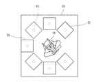
- FIG. 2 is a plan view schematically showing an example of a use environment of the substrate transfer robot of FIG.
- FIG. 3 is a functional block diagram showing a configuration of a control system of the substrate transfer robot of FIG.
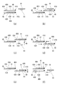
- FIGS. 4A to 4F are schematic diagrams illustrating an example of a substrate exchange operation of the substrate transport robot of the comparative example.
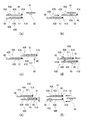
- FIGS. 5A to 5F are schematic diagrams showing an example of a substrate exchange operation of the substrate transfer robot of FIG.
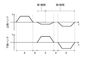
- FIG. 6 is a graph showing a change in the speed of the hand in the substrate exchange operation of the substrate transport robot of the comparative example.
- FIG. 7 is a graph showing a change in the speed of the hand in the substrate exchange operation of the substrate transfer robot of FIG.
- FIG. 1A and 1B are diagrams illustrating an example of a hardware configuration of a substrate transfer robot according to an embodiment of the present invention, wherein FIG. 1A is a plan view and FIG. 1B is a side view.
- FIG. 1B is a diagram of the substrate transfer robot 100 of FIG. 1A as viewed in a substrate transfer direction 200 of FIG. 1 (a), 1 (b), and 2, hatching is applied to essential parts of the upper hand 4A and the lower hand 4B so that the upper hand 4A and the lower hand 4B can be easily distinguished.
- a substrate transfer robot 100 includes a first substrate mounting portion (43 ⁇ / b> A or 43 ⁇ / b> B) for mounting a substrate (not illustrated in FIGS. 1A and 1B) and a first substrate mounting portion ( A first substrate holding mechanism (40A or 40B) for holding and releasing a substrate placed on the substrate 43A or 43B), and a forward and backward operation between a retreat position 201 and a forward position 202 which are positions in the substrate transport direction 200. And a robot controller 20 that controls the operations of the first hand (4A or 4B) and the first substrate holding mechanism (40A or 40B). .
- the robot body 10 includes a second substrate mounting portion (43B or 43A) for mounting a substrate and a second substrate holding mechanism (40B or 40A) for holding and releasing the substrate mounted on the second substrate mounting portion (43B or 43A). And further comprising a second hand (4B or 4A) capable of moving forward and backward between the retracted position 201 and the advanced position 202 below the first hand (4A or 4B), and The first hand (4A or 4B) and the second hand (4B or 4A) are configured to be able to move up and down together, and the robot controller 20 further controls the second hand (4B or 4A). ) And the operation of the second substrate holding mechanism (40B or 40A).
- the first hand is a hand for picking up the board
- the second hand is a hand for putting the board. Since the substrate transfer robot 100 is a dual-arm robot, any hand can function as a first hand or a second hand. Therefore, hereinafter, first, two hands are specified by a structural difference, and it will be described which of the two hands specified as such functions as the first or second hand.
- the substrate transfer robot 100 is a dual-arm robot including a pair of horizontal articulated arms 3A and 3B.
- the substrate transfer robot 100 includes the base 1.
- An elevating body 2 is provided on the base 1.
- the elevating body 2 includes a cylindrical elevating shaft 2a provided on the base 1 so as to be able to elevate and lower, and a revolving body 2b provided to be rotatable around a first rotation axis coinciding with the center axis of the elevating shaft 2a.
- the revolving superstructure 2b is provided with an upper arm 3A and a lower arm 3B.
- One end of the upper arm 3A has an upper first link 31A provided rotatably around a second rotation axis parallel to the first rotation axis at an appropriate position of the revolving structure 2b, and one end has An upper second link 32A provided at the other end of the upper first link 31A so as to be rotatable around a third rotation axis parallel to the second rotation axis, and one end being an upper second link.
- An upper third link 33A rotatably provided around a fourth rotation axis parallel to the third rotation axis at the other end of the upper third link 32A, and one end of the upper third link 33A is the other end of the upper third link 32A.
- the upper part includes an upper fourth link 34A rotatably provided around a fifth rotation axis parallel to the fourth rotation axis, and an upper hand 4A fixed to the upper fourth link 34A.
- the upper first link 31A to the upper fourth link 34A constitute an upper arm portion 35A.
- the lower arm 3B includes a lower first link 31B, one end of which is rotatably provided on the revolving unit 2b around a sixth rotation axis parallel to the first rotation axis.
- the lower first link 31B is provided such that the sixth rotation axis is point-symmetric with the second rotation axis of the first link 31A of the upper arm 3A with respect to the center axis of the revolving unit 2b.
- the lower arm 3B further has one end provided at the other end of the lower first link 31B so as to be rotatable around a seventh rotation axis parallel to the sixth rotation axis.
- the lower first link 31B to the lower third link 33B constitute a lower arm 35B.
- the links 31A to 34A constituting the upper arm 35A and the links 31B to 33B constituting the lower arm 35B are formed of horizontal flat members.
- the upper hand 4A and the lower hand 4B are formed of a plate-like member, and are formed substantially in a Y-shape in plan view.
- the upper hand 4A and the lower hand 4B are provided with an upper substrate holding mechanism 40A and a lower substrate holding mechanism 40B, respectively.
- the upper substrate holding mechanism 40A and the lower substrate holding mechanism 40B are configured by, for example, a gripping mechanism that grips a substrate.
- the upper substrate holding mechanism 40A and the lower substrate holding mechanism 40B may be configured by, for example, a suction mechanism that sucks and releases the substrate.
- a pair of positioning portions 41A for positioning the position of the substrate in the direction from the base end to the front end of the upper hand 4A are provided at the pair of tip portions of the upper hand 4A.
- a pressing portion 42A that presses and depressurizes the substrate by advancing and retreating in a direction from the base end to the distal end of the upper hand 4A and in a direction opposite thereto.
- the pressing portion 42A is moved forward and backward by a power source such as an air cylinder and a motor.
- the pair of positioning portions 41A and the pressing portions 42A constitute an upper substrate holding mechanism 40A.
- the portion between the pressing portion 42A and the pair of positioning portions on the upper surface of the upper hand 4A constitutes the upper substrate mounting portion 43A.
- the pressing portion 42A moves forward and presses the substrate placed on the upper substrate mounting portion 43A, the substrate is pressed against the pair of positioning portions 41A by the pressing portion 42A, and the substrate is pressed against the pressing portion 42A and the pair of positioning portions 41A. Is gripped.
- the pressing portion 42A is retracted, the gripped substrate is released.
- a pair of positioning portions 41B for positioning the position of the substrate in the direction from the base end to the front end of the lower hand 4B are provided at the pair of distal ends of the lower hand 4B.
- a pressing portion 42B which presses and depresses the substrate by advancing and retreating in a direction from the base end to the distal end of the lower hand 4B and in the opposite direction.
- the pressing portion 42B is moved forward and backward by a power source such as an air cylinder and a motor.
- the pair of positioning portions 41B and the pressing portions 42B constitute a lower substrate holding mechanism 40B.
- a portion between the pressing portion 42B and the pair of positioning portions 41B on the upper surface of the lower hand 4B constitutes a lower substrate placing portion 43B.
- the pressing portion 42B moves forward and presses the substrate placed on the lower substrate mounting portion 43B, the substrate is pressed against the pair of positioning portions 41B by the pressing portion 42B, and the substrate is pressed by the pressing portion 42B and the pair of positioning portions 41B. Is gripped.
- the pressing portion 42B is retracted, the gripped substrate is released.
- FIG. 1 shows the substrate transfer robot 100 in a state where the upper hand 4A and the lower hand 4B are located at the retreat position 201 and the forward position, respectively.
- the robot controller 20 determines that the upper hand 4A and the lower hand 4B have the same center line, the center line passes through the first rotation axis of the revolving unit 2b, and The operations of the upper arm 3A and the lower arm 3B are controlled so as to face a predetermined substrate transfer direction 200.
- the retreat position 201 and the advance position 202 are appropriately set according to the usage of the substrate transfer robot 100.
- the retreat position 201 and the advance position 202 are set on a straight line passing through the first rotation axis of the revolving unit 2b in plan view.
- either the upper hand 4A or the lower hand 4B may be the first hand or the second hand described above.
- the robot controller 20 is disposed, for example, inside the base 1 of the robot body 10. Of course, the robot controller 20 may be arranged at a location remote from the robot body 10.
- FIG. 2 is a plan view schematically showing an example of a use environment of the substrate transfer robot of FIG.
- the use environment of the substrate transfer robot 100 is, for example, as follows.
- the robot main body 10 of the substrate transfer robot 100 is placed in the vacuum chamber 51.
- a plurality of substrate processing tanks 52 and one substrate transfer tank 53 are arranged around the robot body 10.
- various types of substrate processing are performed.
- a substrate mounting body 55 is provided in each of the plurality of substrate processing tanks 52 and the substrate delivery tank 53.
- the substrate mounting body 55 is composed of, for example, a columnar body standing on the floor of each of the tanks 52 and 53. In this case, the upper surface of the substrate placing body 55 supports the central part of the substrate (not shown in FIG. 2).
- the substrate mounting body 55 may be formed of a flat plate provided so as to protrude horizontally from the side walls of the tanks 52 and 53.
- the upper surface of the substrate mounting body supports the outer peripheral portion of the substrate.
- an opening / closing mechanism (not shown) for opening and closing the front surfaces is provided on the front surfaces (the surfaces facing the robot body 10) of the plurality of substrate processing tanks 52 and the substrate transfer tank 53.
- the direction from the center (first rotation axis) of the revolving body 2b (see FIG. 1) of the robot body to the center of the substrate mounting body in each of the tanks 52 and 53 is the substrate transport direction 200 (FIG. 1 (a)).
- the center of the substrate mounting body in each of the tanks 52 and 53 is set to the forward position 202 (see FIG. 1A).
- the advance position 202 may be different for each of the tanks 52 and 53.
- the robot body 10 rotates the upper hand 4A and the lower hand 4B so that the substrate transfer direction 200 faces a certain substrate processing tank 52, and the processed substrate placed on the substrate placing body 55 by the upper hand 4A. And the unprocessed substrate held by the lower hand 4B is placed on the substrate placing body 55 to perform the substrate replacement operation.
- the upper hand 4A and the lower hand 4B are turned so that the substrate transfer direction 200 is directed to the substrate transfer tank 53, and the unprocessed substrate placed on the substrate placing body 55 is picked up by the lower hand 4B.
- the substrate replacement operation is performed such that the processed substrate held by the hand 4A is placed on the substrate placement body 55.
- the upper hand 4A functions (operates) as the first hand and the lower hand 4B functions as the second hand. Works (works).
- the lower hand 4B functions (operates) as the first hand and the upper hand 4A functions (operates) as the second hand.
- FIG. 3 is a functional block diagram showing a configuration of a control system of the substrate transport robot 100 of FIG. Referring to FIG. 3, the robot controller 20 performs feedback control on the operation of the robot body 10. The robot controller 20 controls the operations of the upper substrate holding mechanism 40A and the lower substrate holding mechanism 40B.
- the robot controller 20 includes, for example, a processor and a memory.
- the robot controller 20 controls the operations of the robot body 10, the upper substrate holding mechanism 40A, and the lower substrate holding mechanism 40B by causing the processor to read and execute a predetermined operation program stored in the memory.
- the robot controller 20 includes, for example, a microcontroller, an MPU, an FPGA (Field Programmable Gate Array), a PLC (Programmable Logic Controller), a logic circuit, and the like.
- FIGS. 4A to 4F are schematic diagrams showing an example of a substrate exchange operation of the substrate transport robot of the comparative example.
- FIGS. 5A to 5F are schematic diagrams showing an example of a substrate exchange operation of the substrate transfer robot of FIG.
- FIG. 6 is a graph showing a change in the speed of the hand in the substrate exchange operation of the substrate transport robot of the comparative example.
- FIG. 7 is a graph showing a change in the speed of the hand in the substrate exchange operation of the substrate transfer robot of FIG. 4 (a) to 4 (f) and FIGS. 5 (a) to 5 (f) are drawn so that the retreat position and the forward position are closer than those in FIG. ing. 6 and 7, the positive speed indicates the forward speed of the upper hand 4A and the lower hand 4B, and the negative speed indicates the retreat speed of the upper hand 4A and the lower hand 4B.
- the configuration of the substrate transfer robot of the comparative example is the same as that of the substrate transfer robot 100 of the present embodiment, and only the substrate exchange operation is different from the substrate transfer robot 100 of the present embodiment. Therefore, the replacement operation of the substrate transfer robot of the comparative example will be described below with reference to FIGS. 1 and 2 in addition to FIGS. 4A to 4F for convenience.
- the robot controller 20 of the comparative example operates the robot main body 10, the upper substrate holding mechanism 40A, and the lower substrate holding mechanism 40B as follows.
- the upper hand 4A and the lower hand 4B are positioned at the retreat position 201.
- the substrate is not placed on the substrate placing portion 43A, and the upper substrate holding mechanism 40A is in the released state since the pressing portion 42A is retracted.
- the substrate 61 is placed on the substrate placing portion 43B, and in the lower substrate holding mechanism 40B, the pressing portion 42B moves forward to press the substrate 61 against the pair of positioning portions 41B.
- the lower substrate holding mechanism 40B holds the substrate 61 (see FIG. 4A).
- the processed substrate 61 is mounted on the upper surface of the substrate mounting body 55.
- the upper hand 4A is advanced to the advance position 202 (see FIG. 4B).
- the upper hand 4A and the lower hand 4B are raised by a predetermined height.
- This lifting operation is performed by raising the lifting body 2.
- the predetermined height is set such that the lower hand 4B is positioned higher than the upper surface of the substrate placing body 55.
- the processed substrate 61 placed on the substrate placing body 55 is placed on the substrate placing portion 43A of the upper hand 4A (see FIG. 4C).
- the upper hand 4A is retracted to the retracted position 201 and the lower hand 4B is advanced to the advanced position 202.
- the upper substrate holding mechanism 40A of the upper hand 4A holds the substrate 61.
- the lower substrate holding mechanism 40B of the lower hand 4B releases the substrate 61 (see FIG. 4D).
- the upper hand 4A and the lower hand 4B are lowered by a predetermined lowering height.
- This lowering operation is performed by lowering the elevating body 2.
- the predetermined lowering height is set such that the lower hand 4B is positioned lower than the upper surface of the substrate placing body 55.
- the unprocessed substrate 61 placed on the substrate placing portion 43B of the lower hand 4b is placed on the upper surface of the substrate placing body 55 (see FIG. 4E).
- this substrate replacement operation includes operation sections A to E.
- the operation section A the upper hand 4A moves forward.
- the operation section B the upper hand 4A and the lower hand 4B stop and move up.
- the operation section C the upper hand 4A moves backward and the lower hand 4B moves forward.
- the operation section D the upper hand 4A and the lower hand 4B stop and descend.
- the operation section E the lower hand 4B moves backward.
- the speeds of the upper hand 4A and the lower hand 4B in each operation section change so as to include an acceleration section and a deceleration section before and after the constant speed section. Therefore, the absolute value of the speed in the constant speed section in each operation section is the absolute value of the maximum speed in each operation section of the upper hand 4A and the lower hand 4B.
- the absolute value of the maximum speed of the upper hand 4A in the forward and backward directions (the absolute value of the speed in the constant speed section) and the absolute value of the maximum speed of the forward and backward movement of the lower hand 4B (the absolute value of the speed in the constant speed section) And are the same.
- the retreat starts immediately and reaches the maximum speed in a short time. Therefore, when the absolute value of the maximum speed exceeds the absolute value of the speed at which the upper substrate holding mechanism 40A can stably hold the substrate 61, the upper substrate holding mechanism 40A fails to hold the substrate 61. there is a possibility.
- the robot controller 20 of the substrate transfer robot 100 of the present embodiment operates the robot body 10, the upper substrate holding mechanism 40A, and the lower substrate holding mechanism 40B as follows.
- 5A to 5C are the same as the operations of FIGS. 4A to 4C of the comparative example, and thus description thereof is omitted.
- the upper hand 4A and the lower hand 4B are raised by the above-mentioned predetermined height, and the processed substrate 61 mounted on the substrate mounting body 55 is replaced with the substrate of the upper hand 4A.
- the upper hand 4A is retracted to a predetermined position, and the lower hand 4B is advanced to the advance position 202.
- the upper substrate holding mechanism 40A of the upper hand 4A holds the substrate 61.
- the lower substrate holding mechanism 40B of the lower hand 4B releases the substrate 61 (see FIG. 5D).
- the predetermined position is appropriately set in consideration of a retreat time, a speed, and the like in the retreat operation of the upper hand 4A.
- the upper hand 4A and the lower hand 4B are stopped and lowered by the above-described predetermined lowering height.
- the unprocessed substrate 61 placed on the substrate placing portion 43B of the lower hand 4b is placed on the upper surface of the substrate placing body 55 (see FIG. 5E).
- the upper hand 4A and the lower hand 4B are retracted to the retracted position 201 (see FIG. 5F).
- this substrate replacement operation includes operation sections A to E, as in the above-described comparative example.
- the operation section A and the operation section B are the same as those in the above-described comparative example, and thus the description thereof will be omitted.
- the operation section C the upper hand 4A retreats to a predetermined position and the lower hand 4B moves forward.
- the operation section D the upper hand 4A and the lower hand 4B stop and descend.
- the operation section E the upper hand 4A and the lower hand 4B move backward.
- the forward and backward speeds of the upper hand 4A and the forward and backward speeds of the lower hand 4B include an acceleration section and a deceleration section before and after the constant speed section. Change. Therefore, in each operation section, the absolute value of the speed in the constant speed section is the absolute value of the maximum speed of the upper hand 4A and the lower hand 4B in each operation section.
- the absolute value of the maximum forward speed of the upper hand 4A is the same as the absolute value of the maximum forward and backward speed of the lower hand 4B. However, in the retreat of the upper hand 4A, the absolute value of the maximum speed in the operation section C is lower than the absolute value of the maximum speed in the operation section E. Further, the absolute value of the maximum speed of the upper hand 4A in the operation section C is lower than the absolute value of the maximum speed of the upper hand 4A when moving forward and the absolute value of the maximum speed of the lower hand 4B when moving forward and backward.
- the upper board holding mechanism 40A of the upper hand 4A grips (holds) the board 61 in the middle of the operation section C.
- the gripping (holding) operation of the substrate 61 by the upper substrate holding mechanism 40A is preferably performed in a state where the substrate 61 is pressed against the pair of positioning portions 41A by the acceleration due to the retreat of the upper hand 4A. Therefore, the gripping (holding) operation of the substrate 61 by the upper substrate holding mechanism 40A is performed, for example, in the operation section C in a state where the upper hand 4A is accelerated and then attains a constant speed state.
- the period from the start of the retreat of the upper hand 4A to the end of the holding (holding) operation of the substrate 61 of the upper substrate holding mechanism 40A is the first period. Further, a period from the end of the first period until the upper hand 4A is located at the retreat position 201 is a second period.
- the absolute value of the maximum speed of the upper hand 4A in the first period (the absolute value of the speed (first maximum speed) in the constant speed section in the operation section C) is the absolute value of the maximum speed of the upper hand 4A in the second period (operation).
- the speed is set sufficiently lower than the speed (the absolute value of the second maximum speed) of the constant speed section in the section E.
- the absolute value of the speed of the upper hand 4A in the retreat operation may be any value as long as the absolute value of the maximum speed in the first period is lower than the absolute value of the maximum speed in the second period. be able to.
- the upper hand 4A and the lower hand 4B may descend while moving backward and forward at a low speed without stopping.
- the speed of the upper hand 4A may be gradually increased from the start of the retreat to just before the end.
- the upper substrate holding mechanism 40A may hold the substrate 61.
- the substrate 61 placed on the upper substrate placing portion 43A is held by the upper substrate holding mechanism 40A.
- the retreat time of the upper hand 4A can be shortened, and thus, the substrate transfer time can be suppressed from becoming longer. .
- the robot controller 20 causes the upper substrate holding mechanism 40A to hold the substrate 61 placed on the upper substrate placing portion 43A, and whether the upper hand 4A starts to retract or the upper substrate holding.
- the absolute value of the maximum speed of the upper hand 4A in the first period up to the time when the substrate 61 is held by the mechanism 40A is equal to the absolute value of the maximum speed in the second period from the time when the substrate 61 is held to the time when the upper hand 4A finishes retreating.
- the absolute value of the maximum speed in the first period is made sufficiently low as described above, so that the upper substrate mounting portion 43A
- the possibility that the upper substrate holding mechanism 40A fails to hold the substrate 61 placed on the substrate 61 can be reduced.
- the “absolute value of the maximum speed at which the possibility that the upper substrate holding mechanism 40A fails to hold the substrate 61 placed on the upper substrate placing portion 43A” is set by experiments, simulations, calculations, and the like.
- the lower hand 4B functions as a first hand
- the upper hand 4A functions as a second hand.
- the upper hand 4A and the upper substrate holding mechanism 40A are replaced with the lower hand 4B and the lower substrate holding mechanism 40B, respectively.
- the operation is basically the same as the operation in which the lower hand 4B and the lower substrate holding mechanism 40B are replaced with the upper hand 4A and the upper substrate holding mechanism 40A, respectively.
- the “predetermined lowering height” is set such that the upper hand 4A is positioned lower than the upper surface of the substrate mounting body 55.
- the unprocessed substrate 61 is placed on the lower substrate placing portion 43B of the lower hand 4B which has been empty as shown in FIG. 5 (f), as shown in FIG. 5 (a). Is placed on the lower substrate holding mechanism 40B, and the processed substrate 61 held by the upper substrate holding mechanism 40A of the upper hand 4A is delivered as shown in FIG. 5F. As shown in FIG. 5A, the upper substrate holding mechanism 40A is released, and the upper substrate mounting portion 43A is emptied.
- the robot controller 20 causes the upper hand 4A or the lower hand 4B to function as the first hand, in the retreat operation of the upper hand 4A or the lower hand 4B, the first period The upper hand 4A or the lower hand 4B such that the absolute value of the maximum acceleration of the upper hand 4A or the lower hand 4B is lower than the absolute value of the maximum acceleration of the upper hand 4A or the lower hand 4B in the second period. May be controlled.
- the upper substrate holding mechanism 40A or the lower substrate holding mechanism 40B is moved to the upper substrate placing portion 43A or
- the retreat time of the upper hand 4A or the lower hand 4B can be reduced as compared with the case where the substrate placed on the lower substrate placing portion 43B is held, and thus, the increase in the substrate transport time can be suppressed. it can. Further, when the upper hand 4A and the lower hand 4B are moved forward and backward, the possibility that the substrate holding mechanisms 40A and 40B may fail to hold the substrate 61 can be reduced.
- the substrate transfer robot may be a single-arm robot.
- the pair of arms of the substrate transfer robot 100 may be of a vertical articulated type.
- the pair of hands may be provided directly on the revolving unit 2b without an arm.
- the pair of hands are configured so as to be able to move up and down in the substrate transfer direction by being vertically stacked.
- the substrate transfer robot 100 may be used in a use environment other than the use environment of the above embodiment. For example, it can be used for a substrate transfer operation by two robots as described in JP-A-2006-086294.
- the substrate may be other than a circular wafer.
- the substrate may be a glass substrate of a liquid crystal display.
- the upper hand 4A may be a placement hand that holds the substrate only by the frictional force generated between the substrate and the hand due to the weight of the substrate placed on the hand, A hand provided to surround part or all of the side surface, having a wall extending in the vertical direction, and a hand that accommodates a substrate in an area surrounded by the wall and has no gripping mechanism or suction mechanism, It may be a drop-down hand or a known Bernoulli-type hand.
- the forward operation of the lower hand 4B by performing the forward operation of the lower hand 4B in part or all of the operation section A in FIG. 7, at least a part of the forward operation of the upper hand 4A and the forward operation of the lower hand 4B are performed simultaneously. It may be. By doing so, the forward operation time of the lower hand 4B during the substrate replacement operation can be increased. As a result, the absolute value of the speed of the lower hand 4B in the forward operation or the absolute value of the acceleration of the lower hand 4B in the forward operation can be reduced without increasing the time of the board replacement operation. . By lowering the absolute values of the speed and the acceleration of the lower hand 4B, it is possible to prevent the board held by the lower hand 4B from shifting with respect to the lower hand 4B. In this case, the lower hand 4B may not have a gripping mechanism or a suction mechanism.
- the lower hand 4B may be a placing hand, a dropping hand, or a known Bernoulli hand.
- the operation direction of the upper hand 4A and the operation direction of the lower hand 4B may coincide with each other during at least a part of the substrate replacement operation.
- the upper hand 4A may perform the retreat operation in the operation section D of FIG. 7, and the lower hand 4B may perform the forward operation in the operation section B of FIG.
- the substrate transfer robot of the present invention and the control method thereof include a substrate holding mechanism in the hand, and the hand has a substrate holding mechanism, which suppresses the substrate transfer time from being lengthened, and is used when moving the hand forward and backward.
- INDUSTRIAL APPLICABILITY The present invention is useful as a substrate transfer robot capable of reducing a possibility that a substrate holding mechanism may fail to hold a substrate and a control method thereof.
- Reference Signs List 1 base 2 elevating body 2a elevating shaft 2b revolving body 3A upper arm 3B lower arm 4A upper hand 4B lower hand 10 robot body 20 robot controller 40A upper substrate holding mechanism 40B lower substrate holding mechanisms 41A, 41B positioning part 42A , 42B Pressing part 43A Upper substrate placing part 43B Lower substrate placing part 51 Vacuum chamber 52 Substrate processing tank 53 Substrate transfer tank 55 Substrate placing object 100 Substrate transport robot 200 Substrate transport direction 201 Retreat position 202 Forward position
Landscapes
- Engineering & Computer Science (AREA)
- Robotics (AREA)
- Mechanical Engineering (AREA)
- Container, Conveyance, Adherence, Positioning, Of Wafer (AREA)
- Manipulator (AREA)
Abstract
Description
[構成]
図1は本発明の実施形態に係る基板搬送ロボットのハードウェアの構成の一例を示す図であり、(a)は平面図、(b)は側面図である。図1(b)は、図1(a)の基板搬送ロボット100を、図1(a)の基板搬送方向200に見た図である。また、図1(a)、図1(b)、及び図2では、上側ハンド4A及び下側ハンド4Bを判別し易くするために、これらの要部にハッチングが付されている。
図2は、図1の基板搬送ロボットの使用環境の一例を模式的に示す平面図である。図2を参照すると、基板搬送ロボット100の使用環境は、例えば、以下の通りである。
図3は、図1の基板搬送ロボット100の制御系統の構成を示す機能ブロック図である。図3を参照すると、ロボット制御器20は、ロボット本体10の動作をフィードバック制御する。また、ロボット制御器20は、上側基板保持機構40A及び下側基板保持機構40Bの動作を制御する。
次に、以上のように構成された基板搬送ロボット100の動作(基板搬送ロボット100の制御方法)を比較例の基板搬送ロボットと対比して説明する。
まず、基板処理槽52に対する基板入替動作を説明する。
次に、基板受け渡し槽53に対する基板入替動作を説明する。
本変形例では、上述の実施形態において、ロボット制御器20が、上側ハンド4A又は下側ハンド4Bを第1ハンドとして機能させる場合、上側ハンド4A又は下側ハンド4Bの後退動作において、第1期間における上側ハンド4A又は下側ハンド4Bの最大加速度の絶対値が、第2期間における上側ハンド4A又は下側ハンド4Bの最大加速度の絶対値より低加速度であるように上側ハンド4A又は下側ハンド4Bの動作を制御してもよい。
基板搬送ロボットは、単腕のロボットでもよい。
2 昇降体
2a 昇降軸
2b 旋回体
3A 上側アーム
3B 下側アーム
4A 上側ハンド
4B 下側ハンド
10 ロボット本体
20 ロボット制御器
40A 上側基板保持機構
40B 下側基板保持機構
41A、41B 位置決め部
42A、42B 押圧部
43A 上側基板載せ部
43B 下側基板載せ部
51 真空室
52 基板処理槽
53 基板受け渡し槽
55 基板載置体
100 基板搬送ロボット
200 基板搬送方向
201 後退位置
202 前進位置
Claims (6)
- 基板を載せる第1基板載せ部を含み、前進及び後退動作が可能な第1ハンドと、基板を載せる第2基板載せ部を含み、前進及び後退動作が可能な第2ハンドと、を備えるロボット本体と、前記第1ハンド及び前記第2ハンドの動作を制御するロボット制御器と、を備え、
前記ロボット制御器は、前記第1ハンドが、前記第1基板載せ部に前記基板を載せていない状態で前進して、基板載置体に載置された基板を前記第1基板載せ部に載せ、その後、後退するよう前記第1ハンドを動作させ、前記第2ハンドが、前記第2基板載せ部に前記基板を載せた状態で前進して、前記第2ハンドの前記第2基板載せ部に載せた基板を前記基板載置体に載置し、その後、後退するように前記第2ハンドを動作させる基板入替動作を行い、
前記基板入替動作の少なくとも一部の期間において前記第1ハンドの動作方向と前記第2ハンドの動作方向が一致する、基板搬送ロボット。 - 基板を載せる第1基板載せ部を含み、前進及び後退動作が可能な第1ハンドと、基板を載せる第2基板載せ部を含み、前進及び後退動作が可能な第2ハンドと、を備えるロボット本体と、前記第1ハンド及び前記第2ハンドの動作を制御するロボット制御器と、を備え、
前記ロボット制御器は、前記第1ハンドが、前記第1基板載せ部に前記基板を載せていない状態で前進して、基板載置体に載置された基板を前記第1基板載せ部に載せ、その後、後退するよう前記第1ハンドを動作させ、前記第2ハンドが、前記第2基板載せ部に前記基板を載せた状態で前進して、前記第2ハンドの前記第2基板載せ部に載せた基板を前記基板載置体に載置し、その後、後退するように前記第2ハンドを動作させる基板入替動作を行い、
前記第1ハンドの前進動作と前記第2ハンドの前進動作の少なくとも一部が同時に行われる、又は、前記第1ハンドの後退動作と前記第2ハンドの後退動作の少なくとも一部が同時に行われる、基板搬送ロボット。 - 基板を載せる第1基板載せ部と前記第1基板載せ部に載せた基板を保持及び解放する第1基板保持機構とを含み、前記基板の搬送方向における位置である後退位置と前進位置との間で前進及び後退動作が可能な第1ハンドを備えるロボット本体と、前記第1ハンド及び前記第1基板保持機構の動作を制御するロボット制御器と、を備え、
前記ロボット制御器は、前記第1基板保持機構が基板を解放し、且つ、前記第1ハンドが、前記第1基板載せ部に前記基板を載せていない状態で前記後退位置から前記前進位置に前進し、当該前進位置において、基板載置体に載置された基板を前記第1基板載せ部に載せ、その後、前記後退位置に後退するよう前記第1基板保持機構及び前記第1ハンドを動作させ、
前記第1ハンドが後退する期間において、前記第1基板載せ部に載せた基板を前記第1基板保持機構に保持させ、且つ
前記第1ハンドが後退し始めてから前記第1基板保持機構によって前記基板が保持された時点までの第1期間における第1最大速度の絶対値又は第1最大加速度の絶対値が、前記基板が保持された時点から前記第1ハンドが後退を終了するまでの第2期間における第2最大速度の絶対値又は第2加速度の絶対値より低速又は低加速度であるように前記第1ハンドの速度を制御する、基板搬送ロボット。 - 前記第1期間は、前記第1ハンドが前記前進位置から所定距離後退する時間である、請求項3に記載の基板搬送ロボット。
- 前記ロボット本体は、基板を載せる第2基板載せ部と前記第2基板載せ部に載せた基板を保持及び解放する第2基板保持機構とを含み、且つ、前記第1ハンドの下方又は上方において、前記後退位置と前記前進位置との間で前進及び後退動作が可能な第2ハンドをさらに備え、且つ、前記第1ハンドと前記第2ハンドとが一緒に上昇及び下降することが可能なように構成されており、
前記ロボット制御器は、さらに前記第2ハンド及び前記第2基板保持機構の動作を制御するものであり、
前記ロボッット制御器は、前記第1ハンドが前進して前記前進位置に位置するまで、前記第2ハンドを、前記第2基板載せ部に載せた基板を前記第2基板保持機構に保持させた状態で前記後退位置に待機させ、
前記第1ハンドが前記前進位置に位置すると、前記第1ハンド及び前記第2ハンドを所定上昇高さだけ上昇させて、前記基板載置体に載置された基板を前記第1ハンドの前記第1基板載せ部に載せ、
その後、前記第2ハンドを前進させて前記前進位置に位置させるとともに前記第2基板保持機構に前記基板を開放させ、且つ、前記第1ハンドを前記第1期間だけ前記前進位置から後退させるとともに前記第1基板載せ部に載せた基板を前記第1期間において前記第1基板保持機構に保持させ、
その後、前記第1ハンド及び第2ハンドを前記所定下降高さだけ下降させて、前記第2ハンドの前記第2基板載せ部に載せた基板を前記基板載置体に載置し、
その後、前記第1ハンド及び前記第2ハンドを前記後退位置に後退させる、請求項3又は4に記載の基板搬送ロボット。 - 基板を載せる第1基板載せ部と前記第1基板載せ部に載せた基板を保持及び解放する第1基板保持機構とを含み、前記基板の搬送方向における位置である後退位置と前進位置との間で前進及び後退動作が可能な第1ハンドを備えるロボット本体と、前記第1ハンド及び前記第1基板保持機構の動作を制御するロボット制御器と、を備える搬送ロボットの制御方法であって、
前記ロボット制御器は、前記第1基板保持機構が基板を解放し、且つ、前記第1ハンドが、前記第1基板載せ部に前記基板を載せていない状態で前記後退位置から前記前進位置に前進し、当該前進位置において、基板載置体に載置された基板を前記第1基板載せ部に載せ、その後、前記後退位置に後退するよう前記第1基板保持機構及び前記第1ハンドを動作させることと、
前記第1ハンドが後退する期間において、前記第1基板載せ部に載せた基板を前記第1基板保持機構に保持させることと、
前記第1ハンドが後退し始めてから前記第1基板保持機構によって前記基板が保持された時点までの第1期間における第1最大速度の絶対値又は第1最大加速度の絶対値が、前記基板が保持された時点から前記第1ハンドが後退を終了するまでの第2期間における第2最大速度の絶対値又は第2加速度の絶対値より低速又は低加速度であるように前記第1ハンドの速度を制御することと、を行う、基板搬送ロボットの制御方法。
Priority Applications (5)
| Application Number | Priority Date | Filing Date | Title |
|---|---|---|---|
| JP2020529057A JP7382932B2 (ja) | 2018-07-06 | 2019-07-05 | 基板搬送ロボット及びその制御方法 |
| US17/258,368 US12036680B2 (en) | 2018-07-06 | 2019-07-05 | Substrate transfer robot and method of controlling the same |
| CN201980028773.1A CN112005360A (zh) | 2018-07-06 | 2019-07-05 | 基板搬送机器人及其控制方法 |
| KR1020217002600A KR102554053B1 (ko) | 2018-07-06 | 2019-07-05 | 기판 반송 로봇 및 그 제어 방법 |
| US18/741,045 US12318946B2 (en) | 2018-07-06 | 2024-06-12 | Substrate transfer robot and method of controlling the same |
Applications Claiming Priority (2)
| Application Number | Priority Date | Filing Date | Title |
|---|---|---|---|
| JP2018129223 | 2018-07-06 | ||
| JP2018-129223 | 2018-07-06 |
Related Child Applications (2)
| Application Number | Title | Priority Date | Filing Date |
|---|---|---|---|
| US17/258,368 A-371-Of-International US12036680B2 (en) | 2018-07-06 | 2019-07-05 | Substrate transfer robot and method of controlling the same |
| US18/741,045 Continuation US12318946B2 (en) | 2018-07-06 | 2024-06-12 | Substrate transfer robot and method of controlling the same |
Publications (1)
| Publication Number | Publication Date |
|---|---|
| WO2020009214A1 true WO2020009214A1 (ja) | 2020-01-09 |
Family
ID=69059374
Family Applications (1)
| Application Number | Title | Priority Date | Filing Date |
|---|---|---|---|
| PCT/JP2019/026783 Ceased WO2020009214A1 (ja) | 2018-07-06 | 2019-07-05 | 基板搬送ロボット及びその制御方法 |
Country Status (6)
| Country | Link |
|---|---|
| US (2) | US12036680B2 (ja) |
| JP (1) | JP7382932B2 (ja) |
| KR (1) | KR102554053B1 (ja) |
| CN (1) | CN112005360A (ja) |
| TW (1) | TWI743512B (ja) |
| WO (1) | WO2020009214A1 (ja) |
Cited By (1)
| Publication number | Priority date | Publication date | Assignee | Title |
|---|---|---|---|---|
| WO2026100057A1 (ja) * | 2024-11-11 | 2026-05-15 | 株式会社日立ハイテク | 半導体処理装置 |
Families Citing this family (2)
| Publication number | Priority date | Publication date | Assignee | Title |
|---|---|---|---|---|
| JP7382932B2 (ja) * | 2018-07-06 | 2023-11-17 | 川崎重工業株式会社 | 基板搬送ロボット及びその制御方法 |
| KR102584514B1 (ko) * | 2020-07-09 | 2023-10-06 | 세메스 주식회사 | 기판 반송 장치, 기판 처리 장치 및 방법 |
Citations (4)
| Publication number | Priority date | Publication date | Assignee | Title |
|---|---|---|---|---|
| JPH0778858A (ja) * | 1993-06-18 | 1995-03-20 | Tokyo Electron Ltd | 搬送方法および搬送装置 |
| JP2002071753A (ja) * | 2000-08-30 | 2002-03-12 | Yokogawa Electric Corp | ハンドラ |
| JP2006086294A (ja) * | 2004-09-15 | 2006-03-30 | Dainippon Screen Mfg Co Ltd | 基板搬送装置およびそれを用いた基板処理装置、ならびに、それらに用いられる基板搬送方法。 |
| JP2013152998A (ja) * | 2012-01-24 | 2013-08-08 | Yaskawa Electric Corp | ロボットシステム |
Family Cites Families (36)
| Publication number | Priority date | Publication date | Assignee | Title |
|---|---|---|---|---|
| GB2194500B (en) * | 1986-07-04 | 1991-01-23 | Canon Kk | A wafer handling apparatus |
| US5765444A (en) * | 1995-07-10 | 1998-06-16 | Kensington Laboratories, Inc. | Dual end effector, multiple link robot arm system with corner reacharound and extended reach capabilities |
| US6366830B2 (en) * | 1995-07-10 | 2002-04-02 | Newport Corporation | Self-teaching robot arm position method to compensate for support structure component alignment offset |
| US6481956B1 (en) * | 1995-10-27 | 2002-11-19 | Brooks Automation Inc. | Method of transferring substrates with two different substrate holding end effectors |
| JP3722598B2 (ja) * | 1997-07-16 | 2005-11-30 | 株式会社ダイヘン | 2アーム方式の搬送用ロボット装置 |
| US6485250B2 (en) * | 1998-12-30 | 2002-11-26 | Brooks Automation Inc. | Substrate transport apparatus with multiple arms on a common axis of rotation |
| JP2000223549A (ja) * | 1999-01-29 | 2000-08-11 | Canon Inc | 基板搬送装置、基板搬送方法、基板搬送用ハンド機構、灰化処理装置及び灰化処理方法 |
| US6481951B1 (en) * | 1999-09-16 | 2002-11-19 | Applied Materials, Inc. | Multiple sided robot blade for semiconductor processing equipment |
| JP2003289095A (ja) * | 2002-03-28 | 2003-10-10 | Hitachi Kokusai Electric Inc | 半導体製造装置 |
| JP2006041423A (ja) * | 2004-07-30 | 2006-02-09 | Hitachi Naka Electronics Co Ltd | 精密薄板材の搬送装置 |
| US7699021B2 (en) * | 2004-12-22 | 2010-04-20 | Sokudo Co., Ltd. | Cluster tool substrate throughput optimization |
| JP4353903B2 (ja) * | 2005-01-07 | 2009-10-28 | 東京エレクトロン株式会社 | クラスタツールの処理システム |
| JP4372747B2 (ja) | 2005-01-25 | 2009-11-25 | シャープ株式会社 | 輝度レベル変換装置、輝度レベル変換方法、固体撮像装置、輝度レベル変換プログラム、および記録媒体 |
| JP4767641B2 (ja) * | 2005-09-27 | 2011-09-07 | 大日本スクリーン製造株式会社 | 基板処理装置および基板搬送方法 |
| JP5004612B2 (ja) * | 2007-02-15 | 2012-08-22 | 大日本スクリーン製造株式会社 | 基板処理装置 |
| WO2008140728A2 (en) * | 2007-05-08 | 2008-11-20 | Brooks Automation, Inc. | Substrate transport apparatus with multiple movable arms utilizing a mechanical switch mechanism |
| US8267636B2 (en) * | 2007-05-08 | 2012-09-18 | Brooks Automation, Inc. | Substrate transport apparatus |
| KR20090013591A (ko) * | 2007-08-02 | 2009-02-05 | 세메스 주식회사 | 기판 이송 장치 |
| JP2009049200A (ja) * | 2007-08-20 | 2009-03-05 | Tokyo Electron Ltd | 基板処理装置、基板処理方法及び記憶媒体 |
| JP5384925B2 (ja) * | 2008-12-18 | 2014-01-08 | 株式会社日立国際電気 | 基板処理装置及び半導体装置の製造方法 |
| JP5037551B2 (ja) * | 2009-03-24 | 2012-09-26 | 東京エレクトロン株式会社 | 基板交換機構及び基板交換方法 |
| WO2012023156A1 (ja) * | 2010-08-17 | 2012-02-23 | キヤノンアネルバ株式会社 | 基板搬送装置、電子デバイスの製造システムおよび電子デバイスの製造方法 |
| JP5516482B2 (ja) * | 2011-04-11 | 2014-06-11 | 東京エレクトロン株式会社 | 基板搬送方法、基板搬送装置、及び塗布現像装置 |
| KR102030051B1 (ko) * | 2012-09-18 | 2019-10-08 | 세메스 주식회사 | 기판 이송 장치 및 방법 |
| KR101982226B1 (ko) * | 2014-12-26 | 2019-05-24 | 카와사키 주코교 카부시키 카이샤 | 로봇 시스템 |
| JP6759587B2 (ja) | 2015-12-28 | 2020-09-23 | 味の素株式会社 | d14圧電定数を有する圧電フィルムおよびその製造方法 |
| JP6825398B2 (ja) * | 2016-03-25 | 2021-02-03 | 東京エレクトロン株式会社 | 基板搬送装置及び基板搬送方法 |
| US10580681B2 (en) * | 2016-07-10 | 2020-03-03 | Yaskawa America Inc. | Robotic apparatus and method for transport of a workpiece |
| KR101910804B1 (ko) * | 2016-09-12 | 2019-01-04 | 세메스 주식회사 | 이송 로봇 및 기판 픽업 방법 |
| JP7382932B2 (ja) * | 2018-07-06 | 2023-11-17 | 川崎重工業株式会社 | 基板搬送ロボット及びその制御方法 |
| JP7200046B2 (ja) * | 2019-05-31 | 2023-01-06 | 川崎重工業株式会社 | 基板組立装置及び基板組立方法 |
| JP7584857B2 (ja) * | 2020-09-04 | 2024-11-18 | 川崎重工業株式会社 | ロボット及びワーク搬送方法 |
| CN114367972B (zh) * | 2020-10-15 | 2024-06-07 | 北京极智嘉科技股份有限公司 | 一种机器人、机器人控制方法 |
| JP7554663B2 (ja) * | 2020-12-22 | 2024-09-20 | 東京エレクトロン株式会社 | 基板搬送装置、基板処理システム及び基板処理方法 |
| DE102021214567A1 (de) * | 2021-12-17 | 2023-06-22 | Carl Zeiss Industrielle Messtechnik Gmbh | Verfahren und System zur Bewegungssteuerung einer Mehrzahl von Positioniereinrichtungen |
| JP2025029322A (ja) * | 2023-08-21 | 2025-03-06 | 東京エレクトロン株式会社 | 基板搬送装置及び基板搬送方法 |
-
2019
- 2019-07-05 JP JP2020529057A patent/JP7382932B2/ja active Active
- 2019-07-05 US US17/258,368 patent/US12036680B2/en active Active
- 2019-07-05 KR KR1020217002600A patent/KR102554053B1/ko active Active
- 2019-07-05 TW TW108123792A patent/TWI743512B/zh active
- 2019-07-05 WO PCT/JP2019/026783 patent/WO2020009214A1/ja not_active Ceased
- 2019-07-05 CN CN201980028773.1A patent/CN112005360A/zh active Pending
-
2024
- 2024-06-12 US US18/741,045 patent/US12318946B2/en active Active
Patent Citations (4)
| Publication number | Priority date | Publication date | Assignee | Title |
|---|---|---|---|---|
| JPH0778858A (ja) * | 1993-06-18 | 1995-03-20 | Tokyo Electron Ltd | 搬送方法および搬送装置 |
| JP2002071753A (ja) * | 2000-08-30 | 2002-03-12 | Yokogawa Electric Corp | ハンドラ |
| JP2006086294A (ja) * | 2004-09-15 | 2006-03-30 | Dainippon Screen Mfg Co Ltd | 基板搬送装置およびそれを用いた基板処理装置、ならびに、それらに用いられる基板搬送方法。 |
| JP2013152998A (ja) * | 2012-01-24 | 2013-08-08 | Yaskawa Electric Corp | ロボットシステム |
Cited By (1)
| Publication number | Priority date | Publication date | Assignee | Title |
|---|---|---|---|---|
| WO2026100057A1 (ja) * | 2024-11-11 | 2026-05-15 | 株式会社日立ハイテク | 半導体処理装置 |
Also Published As
| Publication number | Publication date |
|---|---|
| US12036680B2 (en) | 2024-07-16 |
| JPWO2020009214A1 (ja) | 2021-08-12 |
| US20240359330A1 (en) | 2024-10-31 |
| TWI743512B (zh) | 2021-10-21 |
| KR102554053B1 (ko) | 2023-07-11 |
| US12318946B2 (en) | 2025-06-03 |
| US20210283779A1 (en) | 2021-09-16 |
| KR20210025080A (ko) | 2021-03-08 |
| JP7382932B2 (ja) | 2023-11-17 |
| CN112005360A (zh) | 2020-11-27 |
| TW202021762A (zh) | 2020-06-16 |
Similar Documents
| Publication | Publication Date | Title |
|---|---|---|
| CN103189168B (zh) | 搬送机械手 | |
| KR102157427B1 (ko) | 기판 반송 로봇 및 기판 처리 시스템 | |
| US12318946B2 (en) | Substrate transfer robot and method of controlling the same | |
| KR101820037B1 (ko) | 기판 반송 장치 | |
| EP3503220A2 (en) | Device and method for turning cell over | |
| JP2014179508A (ja) | 基板処理装置及び基板処理方法 | |
| JP7291760B2 (ja) | キャリッジロボット及びそれを含むタワーリフト | |
| CN100428439C (zh) | 基板处理装置以及基板搬送方法 | |
| JP4889794B2 (ja) | ウエハ搬送ロボット及びウエハの解放方法 | |
| CN112840446A (zh) | 基板移载装置及其控制方法 | |
| WO2013077322A1 (ja) | ワーク搬送システム | |
| CN116985159A (zh) | 一种手臂可升降的机械手 | |
| CN101602205A (zh) | 并联机构 | |
| JP2002151568A (ja) | 被処理体の処理システム及び搬送方法 | |
| JP2014022598A (ja) | 基板搬送装置 | |
| JP6709692B2 (ja) | ロボット、教示用治具およびロボットの教示方法 | |
| CN110035873A (zh) | 机器人的教示方法 | |
| JP2011134820A (ja) | ウェハー搬送ロボット、及び、それを備えた基板処理装置 | |
| CN113727813B (zh) | 基板搬运机器人及基板搬运机器人的控制方法 | |
| CN117067189A (zh) | 一种手臂可升降的机械手 | |
| CN111081619B (zh) | 一种晶圆片传输装置以及方法 | |
| CN112466798B (zh) | 一种半导体机台 | |
| CN209758472U (zh) | 抓手及具有该抓手的移送装置 | |
| CN211529927U (zh) | 硅片输运装置 | |
| CN113380680A (zh) | 硅片输运装置 |
Legal Events
| Date | Code | Title | Description |
|---|---|---|---|
| 121 | Ep: the epo has been informed by wipo that ep was designated in this application |
Ref document number: 19830429 Country of ref document: EP Kind code of ref document: A1 |
|
| ENP | Entry into the national phase |
Ref document number: 2020529057 Country of ref document: JP Kind code of ref document: A |
|
| NENP | Non-entry into the national phase |
Ref country code: DE |
|
| ENP | Entry into the national phase |
Ref document number: 20217002600 Country of ref document: KR Kind code of ref document: A |
|
| 122 | Ep: pct application non-entry in european phase |
Ref document number: 19830429 Country of ref document: EP Kind code of ref document: A1 |