WO2020009196A1 - 空調装置 - Google Patents
空調装置 Download PDFInfo
- Publication number
- WO2020009196A1 WO2020009196A1 PCT/JP2019/026693 JP2019026693W WO2020009196A1 WO 2020009196 A1 WO2020009196 A1 WO 2020009196A1 JP 2019026693 W JP2019026693 W JP 2019026693W WO 2020009196 A1 WO2020009196 A1 WO 2020009196A1
- Authority
- WO
- WIPO (PCT)
- Prior art keywords
- groove
- contact
- central axis
- cylindrical portion
- air
- Prior art date
- Legal status (The legal status is an assumption and is not a legal conclusion. Google has not performed a legal analysis and makes no representation as to the accuracy of the status listed.)
- Ceased
Links
Images






Classifications
-
- B—PERFORMING OPERATIONS; TRANSPORTING
- B60—VEHICLES IN GENERAL
- B60H—ARRANGEMENTS OF HEATING, COOLING, VENTILATING OR OTHER AIR-TREATING DEVICES SPECIALLY ADAPTED FOR PASSENGER OR GOODS SPACES OF VEHICLES
- B60H1/00—Heating, cooling or ventilating devices
-
- H—ELECTRICITY
- H02—GENERATION; CONVERSION OR DISTRIBUTION OF ELECTRIC POWER
- H02K—DYNAMO-ELECTRIC MACHINES
- H02K5/00—Casings; Enclosures; Supports
- H02K5/04—Casings or enclosures characterised by the shape, form or construction thereof
- H02K5/10—Casings or enclosures characterised by the shape, form or construction thereof with arrangements for protection from ingress, e.g. water or fingers
-
- H—ELECTRICITY
- H02—GENERATION; CONVERSION OR DISTRIBUTION OF ELECTRIC POWER
- H02K—DYNAMO-ELECTRIC MACHINES
- H02K5/00—Casings; Enclosures; Supports
- H02K5/24—Casings; Enclosures; Supports specially adapted for suppression or reduction of noise or vibrations
-
- H—ELECTRICITY
- H02—GENERATION; CONVERSION OR DISTRIBUTION OF ELECTRIC POWER
- H02K—DYNAMO-ELECTRIC MACHINES
- H02K7/00—Arrangements for handling mechanical energy structurally associated with dynamo-electric machines, e.g. structural association with mechanical driving motors or auxiliary dynamo-electric machines
- H02K7/14—Structural association with mechanical loads, e.g. with hand-held machine tools or fans
Definitions
- the present invention relates to an air conditioner.
- a motor holder described in Patent Document 1 as a motor holder for mounting a motor to an air conditioning case of an air conditioner.
- This motor holder has an intermediate portion formed with a small thickness between a bottomed tubular portion for housing a motor and a disk-shaped support portion for attaching the tubular portion to an air conditioning case.
- the motor holder is configured such that the rigidity of the intermediate portion in the circumferential direction of the motor is locally reduced, and the vibration transmitted from the motor to the support portion is attenuated.
- the rotating shaft of the motor is rotated by the repulsive force and the attractive force of the magnetic force of the magnet and the magnetic force generated by the coil. Then, when the rotating shaft of the motor rotates, magnetic noise is generated in the motor. If the magnetic noise generated in the motor enters the vehicle interior via an air conditioning duct or the like, the occupant will feel unusual noise. In recent years, in particular, the noise in the vehicle interior has been reduced, and various noises entering the vehicle interior and the blowing noise of the air conditioner have been reduced. In particular, the magnetic noise of the motor entering the vehicle interior has become conspicuous. I have.
- the device described in the above-mentioned patent document can attenuate the vibration transmitted from the motor to the support portion, but cannot suppress wind leakage and water leakage between the air conditioning case and the motor holder.
- the present disclosure aims to further suppress wind and water leakage between the air conditioning case and the motor holder, and to reduce magnetic noise radiated from the motor.
- an air conditioner that performs air conditioning in a vehicle interior includes an air conditioning case that forms a ventilation path through which air blown into the vehicle interior flows, and a fan that generates an air flow in the ventilation path.
- the outer peripheral surface of the cylindrical portion is provided with a groove forming portion which is recessed on one side in the central axis direction of the cylindrical portion and forms a groove extending in the circumferential direction of the cylindrical portion.
- a projection that extends in the circumferential direction of the cylindrical portion while protruding to one side in the direction is provided, and at least one of the groove and the projection is provided with a contact suppression portion that suppresses a contact area between the groove and the projection.
- the contact suppressing portion With the contact suppressing portion, the contact area between the groove and the convex portion is smaller than the cross-sectional area orthogonal to the central axis in a portion of the convex portion located on the other side in the central axis direction of the cylindrical portion than the groove portion. The contact suppressing portion is deformed, and the groove and the convex are fitted.
- At least one of the groove and the protrusion is provided with the contact suppressing portion for suppressing the contact area between the groove and the protrusion, and the contact suppressing portion allows the cylindrical portion of the groove and the protrusion to be formed.
- the contact area in the radial direction about the central axis is smaller than the radial cross-sectional area around the central axis in a portion of the convex portion located on the other side of the cylindrical portion in the central axis direction than the groove. Has become. Therefore, the rigidity of the contact portion between the groove and the protrusion can be reduced, and the magnetic noise radiated from the motor can be reduced.
- the contact suppressing portion is deformed and the groove and the protrusion are fitted, the surface pressure of the contact portion between the groove and the protrusion can be increased, and the air leakage between the air conditioning case and the motor holder can be increased. And water leakage can be further suppressed.
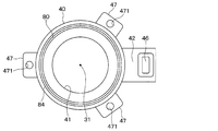
- FIG. 2 is a front view of the motor holder viewed from a direction II in FIG. 1. It is a typical sectional view containing the whole air-conditioning case of an air-conditioning device concerning a 1st embodiment.
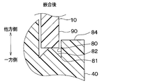
- FIG. 2 is an enlarged view of a V part in FIG. 1 of the air conditioner according to the first embodiment, showing a state before fitting of a groove and a protrusion.
- FIG. 2 is an enlarged view of a V portion in FIG. 1 of the air conditioner according to the first embodiment, and is a diagram illustrating a state in which a groove portion and a convex portion are fitted.
- a rotating shaft of the motor is rotated by a force of attracting and repelling a magnetic force of a magnet and a magnetic force generated by a coil. Then, when the rotating shaft of the motor rotates, magnetic noise is generated in the motor. If the magnetic noise generated in the motor enters the vehicle interior via an air conditioning duct or the like, the occupant will feel unusual noise. In recent years, in particular, the noise in the vehicle interior has been reduced, and various noises entering the vehicle interior and the blowing noise of the air conditioner have been reduced. In particular, the magnetic noise of the motor entering the vehicle interior has become conspicuous. I have.
- the motor holder 40 is fixed to the air conditioning case with screws or the like. It has become.
- the outer diameter of the motor holder is slightly smaller than the inner diameter of the hole formed in the air conditioning case so that the motor holder can be inserted into the hole formed in the air conditioning case.
- the air-conditioning case 10 has a convex portion 90 having a convex shape
- the motor holder 40 has a groove 80 to be fitted with the convex portion 90.
- the protrusion 90 formed on the air-conditioning case 10 and the groove 80 formed on the motor holder 40 are fitted to each other, so that the air-conditioning case 10 is disposed between the air-conditioning case 10 and the motor holder 40 through the ventilation path in the air-conditioning case 10. The wind and water that are leaking to the outside of the device 10 are suppressed.
- the protrusion 90 formed on the air-conditioning case 10 and the groove 80 formed on the motor holder 40 are fitted to each other, so that the motor transmits the motor to the motor holder 40 and the air-conditioning case 10 and is radiated from the air-conditioning case 10. Magnetic sound is suppressed.
- the tip of the convex portion 90 formed on the air conditioning case 10 is flat, and the bottom of the groove 80 formed on the motor holder 40 is also flat. That is, the protrusion 90 formed on the air conditioning case 10 and the bottom of the groove 80 formed on the motor holder 40 are in surface contact.
- Patent Literature 1 can attenuate the vibration transmitted from the motor to the support portion, but cannot suppress wind leakage and water leakage between the air conditioning case and the motor holder. Therefore, it is desirable to further suppress the wind leak and the water leak between the air conditioning case and the motor holder, and to reduce the magnetic noise radiated from the motor.
- the air conditioner of the present embodiment is mounted on a vehicle, sucks one or both of inside air that is air inside the vehicle cabin and outside air that is air outside the vehicle cabin, and adjusts the temperature and humidity of the drawn air into the vehicle cabin. By blowing out, air conditioning in the cabin is performed.
- the air conditioner 1 includes an air conditioning case 10, a fan 20, a motor 30, a motor holder 40, and the like.
- the air-conditioning case 10 is formed of a resin having a certain degree of elasticity and excellent strength.
- a resin forming the air-conditioning case 10 for example, polypropylene is used.
- the air-conditioning case 10 has a ventilation passage 11 on the inside, through which air blown into the vehicle compartment flows.
- the air-conditioning case 10 introduces an inside air inlet 12 for introducing inside air into the ventilation passage 11 from a predetermined location in the vehicle cabin at a location on the upstream side of the ventilation passage 11 in the air flow direction, and introduces outside air to the ventilation passage 11 from outside the vehicle.
- a duct (not shown) configured as a member separate from the air conditioning case 10 may be connected to the inside air inlet 12 or the outside air inlet 13. In that case, air is introduced into the ventilation path 11 from the inside air inlet 12 or the outside air inlet 13 via those ducts.
- the air-conditioning case 10 has a plurality of blowout openings 14, 15, 16 for blowing air from the ventilation passage 11 into the vehicle compartment on the downstream side of the ventilation passage 11 in the air flow direction.
- the air flowing through the ventilation path 11 of the air conditioning case 10 is blown into the vehicle compartment from the plurality of outlets 14, 15, 16.
- the plurality of blowout openings 14, 15, 16 are constituted by a face blowout opening 14, a foot blowout opening 15, and a defroster blowout opening 16.
- the face blowout opening 14 blows out conditioned air toward the upper body of the occupant seated on the front seat or around the upper body.
- the foot outlet 15 blows out conditioned air toward the feet of the occupant.
- the defroster blowing opening 16 blows out conditioned air toward the windshield of the vehicle.
- a duct (not shown) configured as a member separate from the air conditioning case 10 may be connected to each of the plurality of blowout openings 14, 15, 16. In that case, air is blown into the vehicle cabin from the plurality of blowout openings 14, 15, 16 via those ducts.
- the inside / outside air switching door 17, the fan 20, the evaporator 50, the heater core 51, the temperature adjusting door 52, the mode switching doors 53, 54, 55, and the like are provided.
- the inside / outside air switching door 17 is for continuously adjusting the opening area of the inside air inlet 12 and the opening area of the outside air inlet 13.
- the inside / outside air switching door 17 rotates to open one of the inside air inlet 12 and the outside air inlet 13 so as to close the other opening. Thereby, the inside / outside air switching door 17 can adjust the ratio of the amount of air between the inside air and the outside air introduced into the ventilation passage 11.
- a centrifugal fan is employed as the fan 20 of the present embodiment.
- the fan 20 generates a flow of air in the ventilation path 11.
- the motor 30 for rotating the fan 20 is housed in a housing room 410 provided in the motor holder 40 fixed to the air conditioning case 10.
- the fan 20 is fixed to a rotating shaft of the motor 30.
- the fan 20 and the motor 30 constitute a blower.
- the evaporator 50 is a heat exchanger for cooling the air flowing through the ventilation passage 11.
- the evaporator 50 constitutes a well-known refrigeration cycle together with a compressor, a condenser, an expansion valve, and the like (not shown).
- the evaporator 50 is disposed downstream of the expansion valve and upstream of the compressor in the refrigeration cycle.
- the evaporator 50 exchanges heat between the low-temperature and low-pressure refrigerant flowing inside the tube (not shown) and the air passing through the evaporator 50, and cools the air passing through the evaporator 50 by an endothermic effect due to the latent heat of evaporation of the refrigerant. .
- the heater core 51 is a heat exchanger for heating the air flowing through the ventilation passage 11.
- Engine cooling water flows inside a tube (not shown) of the heater core 51.
- the heater core 51 exchanges heat between the engine cooling water flowing inside the tube and the air passing through the heater core 51 to heat the air passing through the heater core 51.
- a temperature adjustment door 52 is provided between the evaporator 50 and the heater core 51.
- the temperature adjustment door 52 adjusts the ratio between the amount of air flowing around the heater core 51 after passing through the evaporator 50 and the amount of air flowing through the heater core 51 after passing through the evaporator 50.
- Mode switching doors 53, 54, 55 for adjusting the opening areas of the face blowout opening 14, the foot blowout opening 15, and the defroster blowout opening 16 are provided.
- the mode switching doors 53, 54, and 55 include a face door 53, a foot door 54, and a defroster door 55.
- the face door 53 opens and closes the face opening 14.
- the foot door 54 opens and closes the foot opening 15.
- the defroster door 55 opens and closes the defroster blowing opening 16.
- the motor holder 40 has a cylindrical portion 41 formed in a cylindrical shape with a bottom, and a duct portion 42 for introducing air from the ventilation passage 11 into the housing chamber 410. are doing.
- the tubular portion 41 is arranged in the hole 10a provided in the air conditioning case 10.
- the hole 10a is formed to penetrate the wall of the air conditioning case 10.
- the outer diameter of the cylindrical portion 41 is slightly smaller than the inner diameter of the hole 10a formed in the air-conditioning case 10 so that the motor holder 40 can be inserted into the hole 10a formed in the air-conditioning case 10. .
- a housing chamber 410 for housing the motor 30 is provided inside the cylindrical portion 41.
- the duct portion 42 is provided with a cooling air passage 45 extending from the storage chamber 410 radially outward of the motor 30, and a cooling air introduction extending from the cooling air passage 45 toward the cooling air supply portion 18 provided in the air conditioning case 10. And a part 46.
- the ventilation passage 11 and the accommodation room 410 communicate with each other through the cooling air supply unit 18, the cooling air introduction unit 46, and the cooling air passage 45.
- Air for cooling the motor 30 is supplied from the ventilation path 11 of the air conditioning case 10 to the housing chamber 410 of the motor holder 40 through the cooling air supply unit 18, the cooling air introduction unit 46, and the cooling air passage 45.
- a plurality of flanges 47 projecting outward in the radial direction are provided on the outer periphery of the bottom side of the motor holder 40.
- the flange portion 47 is provided with a hole 471 communicating with the thickness direction.
- the plurality of support portions 19 extend from the air conditioning case 10 at positions corresponding to the plurality of flange portions 47.
- the plurality of support portions 19 abut against the corresponding flange portions 47, respectively.
- a female screw 191 is formed in a portion of the support portion 19 that comes into contact with the flange portion 47.
- a screw 71 is inserted into a hole 471 of the flange portion 47, and the screw 71 is screwed into a female screw 191 provided on the support portion 19, so that the motor holder 40 is fixed to the air conditioning case 10.
- a convex portion 90 is formed in the air conditioning case 10, and a groove portion 80 is formed in the motor holder 40.
- the projection 90 is formed so as to project to one side in the direction of the central axis 40a of the cylindrical portion 41.
- the convex portion 90 is formed to extend in the circumferential direction of the cylindrical portion 41. More specifically, the protrusion 90 is formed so as to extend over the entire circumference of the tubular portion 41.
- the tip of the convex portion 90 is a flat surface. Note that the central axis 40 a of the cylindrical portion 41 coincides with the axis of the rotation axis of the motor 30.
- a groove forming portion 84 that forms a groove 80 that is recessed on one side in the direction of the central axis 40a of the cylindrical portion 41 is provided.
- a groove 80 is formed on the outer peripheral surface of the cylindrical portion 41 by the groove forming portion 84.
- the groove 80 is formed so as to extend in the circumferential direction of the cylindrical portion 41. More specifically, the groove 80 is formed so as to extend over the entire circumference of the tubular portion 41.
- the motor holder 40 is attached to the air-conditioning case 10 by fitting the protrusions 90 formed on the air-conditioning case 10 and the grooves 80 formed in the motor holder 40.
- the present inventors have conducted intensive studies on this problem, and found that in the configuration shown in FIG. 13, since the protrusion 90 and the bottom of the groove 80 contact unevenly, the radiation of magnetic sound increases. Was found.
- the groove 80 is provided with a contact suppression unit that suppresses a contact area between the groove 80 and the protrusion 90. Due to this contact suppressing portion, the radial contact area of the groove 80 and the convex portion 90 around the central axis 40 a of the cylindrical portion 41 is larger than the groove 80 of the convex portion 90 in the direction of the central axis 40 a of the cylindrical portion 41. Is smaller than the radial cross-sectional area of the cylindrical portion 41 at the portion located on the other side of the cylindrical portion 41 centered on the central axis 40a.
- the contact suppressing portion has a radial contact area around the central axis 40a of the cylindrical portion 41 of the groove 80 and the convex portion 90, and excludes a region of the convex portion 90 where the contact suppressing portion is formed.
- the cross-sectional area in the radial direction centered on the central axis 40a of the cylindrical portion 41 at the site is smaller. Therefore, the contact area between the groove 80 and the tip of the projection 90 is perpendicular to the central axis 40 a in a portion of the projection 90 located on the other side of the cylindrical portion 41 in the direction of the central axis 40 a than the groove 80. It is smaller than the area. Then, the contact suppressing portion is elastically deformed, and the groove portion 80 and the convex portion 90 are fitted.
- the contact suppressing portion of the present embodiment has a groove-side protrusion 82 projecting from the bottom 81 of the groove 80 toward the other side in the direction of the central axis 40 a of the cylindrical portion 41.
- the groove-side projection 82 is formed so as to extend in the circumferential direction of the cylindrical portion 41.
- the groove-side projection 82 and the projection 90 are in line contact with each other.
- the tip of the groove-side protrusion 82 has a sharp shape. ing.
- a groove portion-side projection portion 82 is formed on the bottom portion 81 of the groove portion 80 so as to extend over the entire circumference of the cylindrical portion 41 and have a convex cross-sectional shape in the central axis direction of the cylindrical portion 41. I have.
- the distal end of the groove-side projection 82 can abut on the projection 90 over the entire circumference of the cylindrical portion 41, and furthermore, wind leakage and water leakage between the air-conditioning case 10 and the motor holder 40 are suppressed. At the same time, the emission of magnetic sound is further suppressed.
- the groove-side protrusion 82 is formed at the bottom 81 of the groove 80, the vibration of the motor 30 propagating from the motor holder 40 to the air-conditioning case 10 is also suppressed.
- the motor holder 40 is made of resin, and is in contact with the bottom 81 of the groove 80 with the groove-side projection 82 elastically deformed. Therefore, the sealing property between the groove-side protrusion 82 and the bottom 81 of the groove 80 is ensured, and the wind and water leaks between the air-conditioning case 10 and the motor holder 40 are further suppressed, and the radiation of magnetic noise is also suppressed. Is done.
- the air conditioner of the present embodiment is an air conditioner that performs air conditioning in a vehicle compartment, and includes the air conditioning case 10 that forms a ventilation path 11 through which air blown into the vehicle compartment flows. Further, a fan 20 for generating a flow of air in the ventilation passage 11, a motor 30 for rotating the fan 20, and a motor holder 40 having a cylindrical tubular portion 41 for housing the motor 30 are provided.
- a groove forming portion 84 is provided on the outer peripheral surface of the cylindrical portion so as to be recessed on one side in the direction of the central axis 40a of the cylindrical portion 41 and to form a groove 80 extending in the circumferential direction of the cylindrical portion 41.
- the air-conditioning case 10 is provided with a convex portion 90 that protrudes to one side in the direction of the central axis 40a and extends in the circumferential direction of the cylindrical portion 41.
- the groove portion 80 is provided with a contact suppressing portion for suppressing the contact area between the groove portion 80 and the convex portion 90.
- the contact suppressing portion causes the radial contact area around the central axis of the groove portion 80 and the convex portion 90 to be located on the other side of the convex portion 90 in the central axis direction of the cylindrical portion 41 than the groove portion 80.
- the area becomes smaller than the radial cross-sectional area centered on the central axis 40a, and the contact suppressing portion is elastically deformed so that the groove 80 and the convex 90 are fitted.
- the contact suppressing portion has a groove-side protrusion 82 protruding from the bottom 81 of the groove 80 toward the other side in the direction of the central axis 40a of the cylindrical portion 41, and the groove-side protrusion 82 and the protrusion 90 is in contact.
- the contact suppressing portion can be configured by the groove-side protrusion 82 protruding from the bottom 81 of the groove 80 toward the other side in the direction of the central axis 40a of the cylindrical portion 41.
- the groove portion 80 is provided with the contact suppressing portion for suppressing the contact area between the groove portion 80 and the convex portion 90, and the contact suppressing portion adjusts the central axis 40 a of the groove portion 80 and the convex portion 90.
- the radial contact area with respect to the center is smaller than the radial cross-sectional area with respect to the central axis 40a at the portion of the projection 90 located on the other side of the groove 80 with respect to the central axis 40a. Therefore, the rigidity of the contact portion between the groove 80 and the protrusion 90 can be reduced, and the magnetic sound radiated from the motor 30 can be reduced.
- the contact suppressing portion is elastically deformed and the groove portion 80 and the convex portion 90 are fitted, the surface pressure of the contact portion between the groove portion 80 and the convex portion 90 can be increased, and the air conditioning case 10 and the motor holder It is possible to further suppress the wind leak and the water leak between them.
- the contact suppressing portion is elastically deformed and the groove portion 80 and the convex portion 90 are fitted, the vibration propagating from the motor 30 to the motor holder 40 and the air-conditioning case 10 is attenuated to make it difficult to transmit the vibration. You can also.
- one groove-side projection 82 is formed on the bottom 81 of the groove 80.
- two groove-side projections 82 are formed on the bottom 81 of the groove 80.
- One of the two groove-side protrusions 82 is disposed radially outward of the cylindrical portion 41 from the other of the two groove-side protrusions 82.
- the two groove-side protrusions 82 are elastically deformed, respectively, and are in contact with the protrusions 90.
- the two groove-side protrusions 82 correspond to a contact suppression unit.
- the air conditioner according to the present embodiment has the plurality of groove-side protrusions 82, and the plurality of groove-side protrusions 82 and the protrusions 90 are in contact with each other.
- the contact suppressing portion can be configured by the plurality of groove-side protrusions 82.
- the sealing property between the groove-side projection 82 and the projection 90 is further ensured, so that the wind leak and the water leak between the air-conditioning case 10 and the motor holder 40 can be further suppressed, and the magnetic noise can be further reduced. Radiation can also be suppressed.
- two groove-side protrusions 82 are provided, but three or more groove-side protrusions 82 may be provided.
- the air-conditioning apparatus has a groove-side inclined portion that projects from the bottom 81 of the groove 80 toward the other side in the direction of the central axis 40a of the cylindrical portion 41 as it proceeds inward in the radial direction of the cylindrical portion 41. 83.
- the groove-side inclined portion 83 is in contact with the convex portion 90 while being elastically deformed.
- the groove-side inclined portion 83 corresponds to a contact suppressing portion.
- the air conditioner of the present embodiment is configured such that the other end of the cylindrical portion 41 in the direction of the central axis 40a from the bottom portion 81 of the groove portion 80 toward the radially inward direction centered on the central axis 40a of the cylindrical portion 41. And a groove-side inclined portion 83 projecting so as to be inclined toward the side.
- the groove-side inclined portion 83 and the convex portion 90 are in contact with each other.
- the groove portion protrudes so as to incline from the bottom 81 of the groove portion 80 toward the other side in the direction of the central axis 40a of the cylindrical portion 41 as it proceeds radially inward with the center axis 40a of the cylindrical portion 41 as the center.
- a contact suppressing portion can be configured by the side inclined portion 83.
- a projection-side projection 91 that projects toward one end of the tubular portion 41 is formed at the tip of the projection 90.
- the tip of the projection 91 has a pointed shape.
- the projection-side projection 91 is formed so as to extend over the entire circumference of the cylindrical portion 41. Then, the convex portion-side projection portion 91 is in contact with the groove portion 80 in a state of being elastically deformed.
- the projection-side projection 91 corresponds to a contact suppressing section.
- the air conditioner of the present embodiment has the protrusion-side protrusion 91 formed at the tip of the protrusion 90 and protruding toward one side in the direction of the central axis 40a of the tubular portion 41. I have.
- the projection-side projection 91 and the groove 80 are in contact with each other.
- the contact-side suppressing portion can be configured by the protrusion-side protrusion 91 formed at the tip of the protrusion 90 and protruding toward one side in the direction of the central axis 40a of the cylindrical portion 41.
- two projection-side projections 91 are formed at the tip of the projection 90.
- One of the two projection-side projections 91 is arranged radially outside the cylindrical portion 41 from the other of the two projection-side projections 91.
- the two protrusion-side protrusions 91 are in contact with the grooves 80 in a state of being elastically deformed.
- the two protrusion-side protrusions 91 correspond to a contact suppression unit.
- the air conditioner according to the present embodiment includes the plurality of protrusions 91, and the plurality of protrusions 91 and the groove 80 are in contact with each other.
- the contact suppressing portion can be configured by the plurality of protrusion-side protrusions 91.
- the sealing property between the convex portion-side projection portion 91 and the groove portion 80 is further ensured, and the wind leak and the water leak between the air-conditioning case 10 and the motor holder 40 can be further suppressed. Radiation can also be suppressed.
- two protrusions 91 are provided, but three or more protrusions 91 may be provided.
- the air conditioner according to the present embodiment is configured such that the tip of the convex portion 90 is inclined toward the one side in the direction of the central axis 40a of the cylindrical portion 41 from the distal end of the convex portion 90 as the radially inward direction of the cylindrical portion 41 advances. And a protruding portion-side inclined portion 92 that protrudes from The convex-side inclined portion 92 is formed so as to extend over the entire circumference of the cylindrical portion 41. Then, the convex-side inclined portion 92 is in contact with the groove portion 80 in a state of being elastically deformed. The convex-side inclined portion 92 corresponds to a contact suppressing portion.
- the air conditioner according to the present embodiment is configured such that one end in the direction of the central axis 40a of the cylindrical portion 41 from the distal end of the convex portion 90 as it proceeds in a radially inward direction centered on the central axis 40a of the cylindrical portion 41. It has a convex-side inclined portion 92 projecting so as to be inclined toward the side. The convex-side inclined portion 92 and the groove 80 are in contact with each other.
- the protrusion protrudes so as to incline from the tip of the convex portion 90 toward one side in the direction of the central axis 40a of the cylindrical portion 41 as it proceeds in a radially inward direction around the central axis 40a of the cylindrical portion 41.
- a contact suppressing portion can be configured by the portion-side inclined portion 92.
- the air conditioner according to the present embodiment is configured such that it is inclined from the bottom portion 81 of the groove 80 toward the other side in the direction of the central axis 40a of the cylindrical portion 41 as the air conditioner proceeds inward in the radial direction about the central axis 40a of the cylindrical portion 41.
- a groove-side inclined portion 83 protruding from the groove.
- the air-conditioning device projects from the tip of the convex portion 90 toward one side in the direction of the central axis 40a of the cylindrical portion 41 as the air-conditioning device proceeds inward in the radial direction around the central axis 40a of the cylindrical portion 41.
- the projection-side inclined portion 92 is formed.
- the groove-side inclined section 83 and the convex-side inclined section 92 are in contact with each other in an elastically deformed state.
- the groove-side inclined portion 83 and the convex-side inclined portion 92 correspond to a contact suppressing portion.
- the contact suppressing portion can be configured by the groove-side inclined portion 83 and the convex-portion inclined portion 92.
- the air conditioner according to the present embodiment is configured such that it is inclined from the bottom portion 81 of the groove portion 80 toward the other side in the direction of the central axis 40a of the cylindrical portion 41 as it proceeds in a radially outward direction about the central axis 40a of the cylindrical portion 41. And a groove-side inclined portion 83 protruding from the groove. Further, the air conditioner protrudes from the tip of the convex portion 90 toward one side in the direction of the central axis 40a of the cylindrical portion 41 as the air conditioning device proceeds in a radially outward direction about the central axis 40a of the cylindrical portion 41.
- the groove-side inclined section 83 and the convex-side inclined section 92 are in contact with each other in an elastically deformed state.
- the groove-side inclined portion 83 and the convex-side inclined portion 92 correspond to a contact suppressing portion.
- the contact suppressing portion can be configured by the groove-side inclined portion 83 and the convex-portion inclined portion 92.
- the groove-side inclined portion 83 is inclined from the bottom 81 of the groove 80 toward the other side in the direction of the central axis 40a of the cylindrical portion 41 as the groove advances in the radial direction of the cylindrical portion 41. It is formed so as to protrude.
- the groove-side inclined portion 83 is formed so as to protrude from the bottom 81 of the groove 80 toward the other side in the center axis direction of the cylindrical portion 41 as it proceeds in the radially outward direction of the cylindrical portion 41. May be.
- the convex-side inclined portion 92 is inclined from the tip of the convex portion 90 toward the other side in the center axis direction of the cylindrical portion 41 as it goes inward in the radial direction of the cylindrical portion 41. It is formed so as to protrude.
- the protrusion-side inclined portion 92 projects from the tip of the protrusion 90 toward the other side in the central axis direction of the cylindrical portion 41 as the radially outward direction of the cylindrical portion 41 advances. It may be formed.
- the groove-side inclined portion 83 is inclined from the bottom 81 of the groove 80 toward the other side in the central axis direction of the cylindrical portion 41 as the groove-side inclined portion 83 advances in the radially inner direction of the cylindrical portion 41. It is formed so as to protrude. Further, the projection-side inclined portion 92 is formed so as to project from the tip of the projection toward the other side in the direction of the central axis 40a of the cylindrical portion 41 as it proceeds inward in the radial direction of the cylindrical portion 41. ing.
- a groove-side inclined portion 83 projecting from the bottom 81 of the groove 80 toward the other side in the direction of the central axis of the cylindrical portion 41 as going outward in the radial direction of the cylindrical portion 41
- a configuration may also be adopted in which a convex-side inclined portion 92 is provided which projects from the tip of the convex portion toward the other side in the direction of the center axis of the motor holder as the radial direction of the portion 41 advances.
- the contact suppressing portions 82 to 83 and 91 to 92 are elastically deformed so that the groove 80 and the projection 90 are fitted.
- the contact suppressing portions 82 to 83 and 91 to 92 may be plastically deformed so that the groove portion 80 and the convex portion 90 are fitted.
- the air conditioner is an air conditioner that performs air conditioning in a vehicle compartment, and has an air passage through which air blown into the vehicle compartment flows. And an air-conditioning case to be formed. Furthermore, it includes a fan that generates a flow of air in the ventilation path, a motor that rotates the fan, and a motor holder that has a cylindrical portion that houses the motor. In addition, a groove forming portion is formed on the outer peripheral surface of the cylindrical portion so as to be concave on one side in the central axis direction of the cylindrical portion and form a groove extending in the circumferential direction of the cylindrical portion.
- the air-conditioning case is provided with a convex portion that protrudes to one side in the central axis direction of the cylindrical portion and extends in the circumferential direction of the cylindrical portion.
- At least one of the groove and the protrusion is provided with a contact suppressing portion for suppressing a contact area between the groove and the protrusion.
- the contact area between the groove and the convex portion is smaller than the cross-sectional area orthogonal to the central axis in a portion of the convex portion located on the other side in the central axis direction of the cylindrical portion than the groove, The contact suppressing portion is deformed, and the groove and the convex are fitted.
- the contact suppressing portion has the groove-side protrusion protruding from the bottom of the groove toward the other side in the central axis direction, and the groove-side protrusion contacts the protrusion. I have.
- the contact suppressing portion can be configured by the groove-side protrusion projecting from the bottom of the groove toward the other side in the central axis direction.
- the contact suppressing portion has a plurality of groove-side protrusions, and the plurality of groove-side protrusions are in contact with the protrusions.
- the contact suppressing portion moves from the bottom of the groove to the other side in the direction of the central axis of the cylindrical portion from the bottom of the groove toward the radially outward direction or the radially inward direction around the central axis of the cylindrical portion.
- a groove-side inclined portion protruding so as to incline toward the groove, and the groove-side inclined portion is in contact with the convex portion.
- the groove-side inclination protrudes so as to incline from the bottom of the groove toward the other side in the direction of the center axis of the cylindrical portion from the bottom of the groove toward the radially outward direction or the radially inward direction around the central axis of the cylindrical portion.
- the contact suppressing section can be constituted by the section.
- the contact suppressing portion has a projection-side projection projecting from the tip of the projection toward one side in the central axis direction of the cylindrical portion.
- the groove is in contact.
- the contact suppressing portion can also be configured by the projection-side projection projecting from the tip of the projection toward one side in the central axis direction of the cylindrical portion.
- the contact suppressing portion has a plurality of protrusion side protrusions, and the plurality of protrusion side protrusions are in contact with the grooves.
- the contact suppressing portion moves from the tip of the convex portion to the other side in the central axis direction of the motor holder as it proceeds in a radially outward direction or a radially inward direction around the central axis of the cylindrical portion.
- a convex-side inclined portion protruding so as to be inclined toward the convex portion, and the convex-side inclined portion and the groove are in contact with each other.
- a suppression unit can also be configured.
- the contact suppressing portion projects so as to incline from the bottom of the groove toward the other side in the central axis direction as the contact suppressing portion advances radially inward about the central axis of the cylindrical portion. It has a groove-side inclined portion. Furthermore, it has a convex-side inclined portion that protrudes so as to incline from the tip of the convex portion toward one side in the central axis direction as it proceeds in a radially inward direction around the central axis.
- the groove-side slope and the protrusion-side slope are in contact with each other.
- the contact suppressing portion can be configured by the groove-side inclined portion and the convex-portion-side inclined portion.
- the contact suppressing portion includes a groove-side inclined portion that projects from the bottom of the groove toward the other side in the central axis direction as it proceeds in a radially outward direction about the central axis. have.
- it has a projection-side inclined portion that projects from the tip of the projection toward one side in the direction of the central axis as it proceeds radially outward with the center axis as the center.
- the groove-side slope and the protrusion-side slope are in contact with each other.
- the contact suppressing portion can be configured by the groove-side inclined portion and the convex-portion-side inclined portion.
- the groove-side protrusion 82, the groove-side slope 83, the protrusion-side protrusion 91, and the protrusion-side slope 92 correspond to a contact suppressing part.
Landscapes
- Engineering & Computer Science (AREA)
- Power Engineering (AREA)
- Physics & Mathematics (AREA)
- Thermal Sciences (AREA)
- Mechanical Engineering (AREA)
- Air-Conditioning For Vehicles (AREA)
- Motor Or Generator Frames (AREA)
- Connection Of Motors, Electrical Generators, Mechanical Devices, And The Like (AREA)
Abstract
空調装置は、空調ケース(10)と、ファン(20)と、ファンを回転させるモータ(30)と、モータを収容する筒状部(41)を有するモータホルダ(40)と、を備える。筒状部の外周面には、筒状部の中心軸(40a)方向の一方側に凹むとともに筒状部の周方向に延びる溝部(80)を形成する溝形成部(84)が設けられ、空調ケースには、筒状部の中心軸方向の一方側に突出するとともに筒状部の円周方向に延びる凸部(90)が設けられ、溝部および凸部の少なくとも一方には、溝部および凸部の接触面積を抑制する接触抑制部(82~83、91~92)が設けられており、接触抑制部により、溝部と凸部の接触面積が、凸部のうち溝部よりも筒状部の中心軸方向の他方側に位置する部位における中心軸に直交する断面積よりも小さくなるとともに、接触抑制部が変形して溝部と凸部とが嵌合している。
Description
本出願は、2018年7月5日に出願された日本特許出願番号2018-128136号に基づくもので、ここにその記載内容が参照により組み入れられる。
本発明は、空調装置に関するものである。
従来、空調装置の空調ケースに対しモータを取り付けるモータホルダとして特許文献1に記載されたものがある。このモータホルダは、モータを収容する有底筒状の筒状部と、その筒状部を空調ケースに取り付けるための円盤状の支持部との間に、肉厚が薄く形成された中間部を備えている。これにより、このモータホルダは、モータの周方向における中間部の剛性が局部的に低くなるよう構成され、モータから支持部に伝わる振動が減衰するようになっている。
このようなモータにおいては、磁石の磁力とコイルで発生した磁力の引き合う力と反発する力によってモータの回転軸が回転する。そして、モータの回転軸が回転する際にモータ内で磁気音が発生する。このモータ内で発生した磁気音が空調ダクト等を経由して車室内に進入すると乗員に異音と感じさせてしまう。近年、特に車室内の静音化が進み、車室内に入ってくる各種雑音や空調装置の送風騒音等が小さくなってきており、特に車室内に進入するモータの磁気音が目立つようになってきている。
また、上記特許文献に記載された装置は、モータから支持部に伝わる振動を減衰させることはできるが、空調ケースとモータホルダとの間の風漏れおよび水漏れを抑制するといったことはできない。
本開示は、空調ケースとモータホルダとの間の風漏れおよび水漏れをより抑制するとともに、モータから放射される磁気音を低減することを目的とする。
本開示の1つの観点によれば、車室内の空気調和を行う空調装置は、車室内に送風される空気が流れる通風路を形成する空調ケースと、通風路に空気の流れを発生させるファンと、ファンを回転させるモータと、モータを収容する円筒状の筒状部を有するモータホルダと、を備えている。また、筒状部の外周面には、筒状部の中心軸方向の一方側に凹むとともに筒状部の周方向に延びる溝部を形成する溝形成部が設けられ、空調ケースには、中心軸方向の一方側に突出するとともに筒状部の円周方向に延びる凸部が設けられ、溝部および凸部の少なくとも一方には、溝部および凸部の接触面積を抑制する接触抑制部が設けられており、接触抑制部により、溝部と凸部の接触面積が、凸部のうち溝部よりも筒状部の中心軸方向の他方側に位置する部位における中心軸に直交する断面積よりも小さくなるとともに、接触抑制部が変形して溝部と凸部とが嵌合している。
このような構成によれば、溝部および凸部の少なくとも一方には、溝部および凸部の接触面積を抑制する接触抑制部が設けられており、接触抑制部により、溝部および凸部の筒状部の中心軸を中心とする径方向の接触面積が、凸部のうち溝部よりも筒状部の中心軸方向の他方側に位置する部位における中心軸を中心とする径方向の断面積よりも小さくなっている。したがって、溝部および凸部の接触部の剛性を低下させることができ、モータから放射される磁気音を低減することができる。
さらに、接触抑制部が変形して溝部と凸部とが嵌合しているので、溝部および凸部の接触部の面圧を大きくすることができ、空調ケースとモータホルダとの間の風漏れおよび水漏れをより抑制することができる。
なお、各構成要素等に付された括弧付きの参照符号は、その構成要素等と後述する実施形態に記載の具体的な構成要素等との対応関係の一例を示すものである。
まず、実施形態の課題について説明する。特許文献1のようなモータにおいては、磁石の磁力とコイルで発生した磁力の引き合う力と反発する力によってモータの回転軸が回転する。そして、モータの回転軸が回転する際にモータ内で磁気音が発生する。このモータ内で発生した磁気音が空調ダクト等を経由して車室内に進入すると乗員に異音と感じさせてしまう。近年、特に車室内の静音化が進み、車室内に入ってくる各種雑音や空調装置の送風騒音等が小さくなってきており、特に車室内に進入するモータの磁気音が目立つようになってきている。
このようなモータにおいては、車室内に送風される空気が流れる通風路を形成する空調ケースを貫通する穴部にモータホルダが挿入された後、ねじ等によりモータホルダ40が空調ケースに固定されるようになっている。なお、空調ケースに形成された穴部にモータホルダを挿入できるようにするため、モータホルダの外径は、空調ケースに形成された穴部の内径よりも若干小さくなっている。
また、図13に示すように、空調ケース10には、凸形状を成す凸部90が形成され、モータホルダ40には、凸部90と嵌合する溝部80が形成されている。そして、空調ケース10に形成された凸部90とモータホルダ40に形成された溝部80とを嵌合させることによって空調ケース10内の通風路から空調ケース10とモータホルダ40との間から空調ケース10の外部へ漏れようとする風および水が抑制されるようになっている。また、空調ケース10に形成された凸部90とモータホルダ40に形成された溝部80とを嵌合させることによってモータからモータホルダ40、空調ケース10へと伝達し、空調ケース10から放射される磁気音が抑制されるようになっている。
しかしながら、図13に示したように、空調ケース10に形成された凸部90の先端とが平面となっており、さらに、モータホルダ40に形成された溝部80の底部も平面となっている。すなわち、空調ケース10に形成された凸部90とモータホルダ40に形成された溝部80の底部が面接触となっている。
このため、空調ケース10に形成された凸部90とモータホルダ40に形成された溝部80の接触部に隙間が形成されやすく、空調ケース10内の通風路から空調ケース10とモータホルダ40との間を通って空調ケース10の外部へ風や水が漏れてしまうといった問題があった。また、空調ケース10に形成された凸部90とモータホルダ40に形成された溝部80の底部が面接触となるので、モータからモータホルダ40、空調ケース10へと磁気音が伝搬しやすく、空調ケース10から放射される磁気音が大きくなるといった問題もあった。
なお、特許文献1に記載された装置は、モータから支持部に伝わる振動を減衰させることはできるが、空調ケースとモータホルダとの間の風漏れおよび水漏れを抑制するといったことはできない。したがって、空調ケースとモータホルダとの間の風漏れおよび水漏れをより抑制するとともに、モータから放射される磁気音を低減することが望ましい。
以下、本開示の実施形態について図に基づいて説明する。なお、以下の各実施形態相互において、互いに同一もしくは均等である部分には、図中、同一符号を付してある。
(第1実施形態)
第1実施形態の空調装置について図1~図5を用いて説明する。本実施形態の空調装置は、車両に搭載され、車室内の空気である内気と車室外の空気である外気の一方または両方を吸い込み、その吸い込んだ空気の温度および湿度を調整して車室内に吹き出すことで、車室内の空気調和を行う。
第1実施形態の空調装置について図1~図5を用いて説明する。本実施形態の空調装置は、車両に搭載され、車室内の空気である内気と車室外の空気である外気の一方または両方を吸い込み、その吸い込んだ空気の温度および湿度を調整して車室内に吹き出すことで、車室内の空気調和を行う。
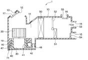
図3に示すように、空調装置1は、空調ケース10、ファン20、モータ30、モータホルダ40などを備えている。
空調ケース10は、ある程度の弾性を有し、強度的にも優れた樹脂にて形成されている。空調ケース10を形成する樹脂として、例えばポリプロピレンが挙げられる。空調ケース10は内側に、車室内に送風される空気が流れる通風路11を有している。
空調ケース10は、通風路11の空気流れ方向上流側の部位に、車室内の所定箇所から通風路11に内気を導入するための内気導入口12と、車外から通風路11に外気を導入するための外気導入口13を有している。なお、内気導入口12または外気導入口13には、空調ケース10とは別部材として構成された図示していないダクトを接続してもよい。その場合、それらのダクトを介して、内気導入口12または外気導入口13から通風路11に空気が導入される。
空調ケース10は、通風路11の空気流れ方向下流側に、通風路11から車室内に空気を送風するための複数の吹出開口部14、15、16を有している。空調ケース10の通風路11を流れる空気は、複数の吹出開口部14、15、16から車室内に送風される。複数の吹出開口部14、15、16は、フェイス吹出開口部14、フット吹出開口部15、デフロスタ吹出開口部16により構成されている。フェイス吹出開口部14は、前座席に着座した乗員の上半身またはその周囲に向けて空調風を吹き出すものである。フット吹出開口部15は、その乗員の足元に向けて空調風を吹き出すものである。デフロスタ吹出開口部16は、車両のフロントガラスに向けて空調風を吹き出すものである。
なお、複数の吹出開口部14、15、16にはそれぞれ、空調ケース10とは別部材として構成された図示していないダクトを接続してもよい。その場合、それらのダクトを介して、複数の吹出開口部14、15、16から車室内に空気が吹き出される。
空調ケース10の内側には、内外気切替ドア17、ファン20、エバポレータ50、ヒータコア51、温度調整ドア52およびモード切替ドア53、54、55などが設けられている。
内外気切替ドア17は、内気導入口12の開口面積と、外気導入口13の開口面積とを連続的に調整するものである。内外気切替ドア17は、内気導入口12と外気導入口13のうち、一方の開口部を開くほど他方の開口部を閉じるように回転動作する。これにより、内外気切替ドア17は、通風路11に導入される内気と外気の風量割合を調整することが可能である。
本実施形態のファン20として、遠心ファンが採用されている。ファン20は、通風路11に空気の流れを発生させる。ファン20を回転させるモータ30は、空調ケース10に固定されるモータホルダ40に設けられた収容室410に収容されている。ファン20は、モータ30の回転軸に固定されている。ファン20とモータ30により送風機が構成される。
モータ30の駆動に伴ってファン20が回転すると、通風路11に気流が発生する。これにより、内気導入口12または外気導入口13から通風路11に内気または外気が導入される。ファン20により送風されて通風路11を流れる空気は、エバポレータ50およびヒータコア51により温度および湿度が調整され、通風路11に連通する複数の吹出開口部14、15、16のいずれかを経由して車室内に吹き出される。
エバポレータ50は、通風路11を流れる空気を冷却するための熱交換器である。エバポレータ50は、図示していない圧縮機、凝縮器および膨張弁などと共に周知の冷凍サイクルを構成している。エバポレータ50は、冷凍サイクルにおいて、膨張弁の下流側、且つ、圧縮機の上流側に配置されている。エバポレータ50は、図示していないチューブの内側を流れる低温低圧の冷媒と、エバポレータ50を通過する空気との熱交換を行い、冷媒の蒸発潜熱による吸熱作用により、エバポレータ50を通過する空気を冷却する。
ヒータコア51は、通風路11を流れる空気を加熱するための熱交換器である。ヒータコア51が有する図示していないチューブの内側をエンジン冷却水が流れる。ヒータコア51は、そのチューブの内側を流れるエンジン冷却水と、ヒータコア51を通過する空気との熱交換を行い、ヒータコア51を通過する空気を加熱する。
エバポレータ50とヒータコア51との間には、温度調整ドア52が設けられている。温度調整ドア52は、エバポレータ50を通過した後にヒータコア51を迂回して流れる風量と、エバポレータ50を通過した後にヒータコア51を通過する風量との割合を調整する。
フェイス吹出開口部14、フット吹出開口部15およびデフロスタ吹出開口部16には、それぞれの開口面積を調整するためのモード切替ドア53、54、55が設けられている。モード切替ドア53、54、55は、フェイスドア53、フットドア54およびデフロスタドア55により構成されている。フェイスドア53は、フェイス吹出開口部14を開閉する。フットドア54は、フット吹出開口部15を開閉する。デフロスタドア55は、デフロスタ吹出開口部16を開閉する。
図1および図2に示すように、モータホルダ40は、有底円筒状に形成された筒状部41と、通風路11から収容室410に空気を導入するためのダクト部42と、を有している。
また、筒状部41は、空調ケース10に設けられた穴部10aに配置されている。なお、穴部10aは、空調ケース10の壁面を貫通するように形成されている。空調ケース10に形成された穴部10aにモータホルダ40を挿入できるようにするため、筒状部41の外径は、空調ケース10に形成された穴部10aの内径よりも若干小さくなっている。
筒状部41の内部には、モータ30を収容するための収容室410が設けられている。ダクト部42は、収容室410からモータ30の径方向外側に向けて延びる冷却風通路45と、冷却風通路45から空調ケース10に設けられた冷却風供給部18側に向けて延びる冷却風導入部46と、を有している。
通風路11と収容室410は、冷却風供給部18、冷却風導入部46および冷却風通路45を介して連通している。空調ケース10の通風路11から、冷却風供給部18、冷却風導入部46および冷却風通路45を通じて、モータホルダ40の収容室410にモータ30を冷却するための空気が供給される。
モータホルダ40の底部側の外周には、径方向外側に突出する複数のフランジ部47が設けられている。フランジ部47には、板厚方向に通じる穴471が設けられている。
一方、複数のフランジ部47に対応する位置に、空調ケース10から複数の支持部19が延びている。複数の支持部19はそれぞれ対応するフランジ部47に当接する。支持部19のうち、フランジ部47に当接する部位には、雌ねじ191が形成されている。
フランジ部47が有する穴471にねじ71が差し込まれ、そのねじ71が支持部19に設けられた雌ねじ191に螺合することで、モータホルダ40が空調ケース10に固定される。
また、図5に示すように、空調ケース10には、凸部90が形成され、モータホルダ40には、溝部80が形成されている。
凸部90は、筒状部41の中心軸40a方向の一方側に突出するように形成されている。また、凸部90は、筒状部41の周方向に延びるように形成されている。より具体的には、凸部90は、筒状部41の全周にわたって延びるように形成されている。また、凸部90の先端は平面となっている。なお、筒状部41の中心軸40aは、モータ30の回転軸の軸線と一致している。
一方、筒状部41の外周面には、筒状部41の中心軸40a方向の一方側に凹む溝部80を形成する溝形成部84が設けられている。溝形成部84により、筒状部41の外周面に溝部80が形成されている。溝部80は、筒状部41の周方向に延びるように形成されている。より具体的には、溝部80は、筒状部41の全周にわてって延びるように形成されている。
そして、空調ケース10に形成された凸部90と筒状部41に形成された溝部80とが嵌合することにより、空調ケース10とモータホルダ40との間の風漏れおよび水漏れが抑制されるとともに、磁気音の放射が抑制されるようになっている。また、空調ケース10に形成された凸部90とモータホルダ40に形成された溝部80とが嵌合することにより、モータホルダ40が空調ケース10に取り付けられる。
ところで、図13に示したように、空調ケース10に形成された凸部90とモータホルダ40に形成された溝部80の底部が面接触となっている構成では、空調ケース10とモータホルダ40との間の風漏れおよび水漏れを十分に抑制できない。さらに、磁気音の放射を十分に抑制できない。
この問題について、本発明者らは鋭意検討を行ったところ、図13に示した構成では、凸部90と溝部80の底部が不均一に接触するために、磁気音の放射が大きくなるということを見出した。
また、風漏れおよび水漏れを抑制するためには、空調ケース10に形成された凸部90とモータホルダ40に形成された溝部80の底部の接触状態を適切な状態にする必要がある。具体的には、凸部90と溝部80の底部の接触面の面圧を適切な状態にする必要がある。
しかし、図13に示したように、空調ケース10に形成された凸部90とモータホルダ40に形成された溝部80の底部が面接触となっている構成では、凸部90と溝部80の底部の各接触面に凹凸ができてしまう。このため、凸部90と溝部80の底部の接触面の面圧を適切な状態にするのが困難であり、空調ケース10とモータホルダ40との間の風漏れおよび水漏れを十分に抑制するのは困難であることが分かった。
そこで、本実施形態の空調装置は、図5に示すように、溝部80に、溝部80および凸部90の接触面積を抑制する接触抑制部が設けられている。この接触抑制部により、溝部80および凸部90の筒状部41の中心軸40aを中心とする径方向の接触面積が、凸部90のうち溝部80よりも筒状部41の中心軸40a方向の他方側に位置する部位における筒状部41の中心軸40aを中心とする径方向の断面積よりも小さくなる。即ち、接触抑制部により、溝部80および凸部90の筒状部41の中心軸40aを中心とする径方向の接触面積が、凸部90のうち接触抑制部が形成されている領域を除いた部位における筒状部41の中心軸40aを中心とする径方向の断面積よりも小さくなる。したがって、溝部80と凸部90の先端部との接触面積が、凸部90のうち溝部80よりも筒状部41の中心軸40a方向の他方側に位置する部位における中心軸40aに直交する断面積よりも、小さくなる。そして、接触抑制部が弾性変形して溝部80と凸部90とが嵌合している。
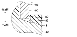
本実施形態の接触抑制部は、溝部80の底部81から筒状部41の中心軸40a方向の他方側に向かって突出する溝部側突起部82を有している。溝部側突起部82は、筒状部41の周方向に延びるように形成されている。そして、溝部側突起部82と凸部90とが線接触する構成となっている。
図4に示すように、空調ケース10に形成された凸部90とモータホルダ40に形成された溝部80が嵌合する前の状態では、溝部側突起部82の先端は尖った形状を成している。
空調ケース10に形成された凸部90とモータホルダ40に形成された溝部80が嵌合した状態では、図5に示すように、ねじ71が、複数のフランジ部47、モータホルダ40および空調ケース10を固定する。この固定する力により、溝部側突起部82の先端が弾性変形した状態で凸部90の先端と接触する。
本実施形態の空調装置は、溝部80の底部81に、筒状部41の全周にわたって延びるとともに筒状部41の中心軸軸方向断面形状が凸形状を成す溝部側突起部82が形成されている。
したがって、筒状部41の全周にわたって溝部側突起部82の先端が凸部90と当接することができ、さらに、空調ケース10とモータホルダ40との間の風漏れおよび水漏れが抑制されるとともに、さらに、磁気音の放射が抑制される。
図13に示したように、溝部80の底部81が平面形状となっている場合、溝部80と凸部90の接触面積が大きくなるため、モータホルダ40から空調ケース10に伝搬するモータ30の振動も大きくなる。
しかし、本実施形態の空調装置は、溝部80の底部81に溝部側突起部82が形成されているので、モータホルダ40から空調ケース10に伝搬するモータ30の振動も抑制される。
また、モータホルダ40は、樹脂により構成されており、溝部側突起部82が弾性変形した状態で、溝部80の底部81と当接している。したがって、溝部側突起部82と溝部80の底部81とのシール性が確保され、より空調ケース10とモータホルダ40との間の風漏れおよび水漏れが抑制され、さらに、磁気音の放射も抑制される。
以上、説明したように、本実施形態の空調装置は、車室内の空気調和を行う空調装置であって、車室内に送風される空気が流れる通風路11を形成する空調ケース10を備えている。また、通風路11に空気の流れを発生させるファン20と、ファン20を回転させるモータ30と、モータ30を収容する円筒状の筒状部41を有するモータホルダ40と、を備えている。
また、筒状部の外周面には、筒状部41の中心軸40a方向の一方側に凹むとともに筒状部41の周方向に延びる溝部80を形成する溝形成部84が設けられている。また、空調ケース10には、中心軸40a方向の一方側に突出するとともに筒状部41の円周方向に延びる凸部90が設けられている。
また、溝部80には、溝部80および凸部90の接触面積を抑制する接触抑制部が設けられている。そして、接触抑制部により、溝部80および凸部90の中心軸を中心とする径方向の接触面積が、凸部90のうち溝部80よりも筒状部41の中心軸方向の他方側に位置する部位における中心軸40aを中心とする径方向の断面積よりも小さくなるとともに、接触抑制部が弾性変形して溝部80と凸部90とが嵌合している。
具体的には、接触抑制部は、溝部80の底部81から筒状部41の中心軸40a方向の他方側に向かって突出する溝部側突起部82を有し、溝部側突起部82と凸部90とが接触している。このように、溝部80の底部81から筒状部41の中心軸40a方向の他方側に向かって突出する溝部側突起部82により接触抑制部を構成することができる。
このような構成によれば、溝部80には、溝部80および凸部90の接触面積を抑制する接触抑制部が設けられており、接触抑制部により、溝部80および凸部90の中心軸40aを中心とする径方向の接触面積が、凸部90のうち溝部80よりも中心軸40a方向の他方側に位置する部位における中心軸40aを中心とする径方向の断面積よりも小さくなっている。したがって、溝部80および凸部90の接触部の剛性を低下させることができ、モータ30から放射される磁気音を低減することができる。
さらに、接触抑制部が弾性変形して溝部80と凸部90とが嵌合しているので、溝部80および凸部90の接触部の面圧を大きくすることができ、空調ケース10とモータホルダ40との間の風漏れおよび水漏れをより抑制することができる。
また、接触抑制部が弾性変形して溝部80と凸部90とが嵌合しているので、モータ30からモータホルダ40、空調ケース10へと伝搬する振動を減衰させて振動を伝達し難くすることもできる。
(第2実施形態)
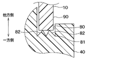
第2実施形態に係る空調装置について図6を用いて説明する。上記第1実施形態の空調装置は、溝部80の底部81に1つの溝部側突起部82が形成されている。これに対し、本実施形態の空調装置は、溝部80の底部81に2つの溝部側突起部82が形成されている。2つの溝部側突起部82の一方は、2つの溝部側突起部82の他方よりも筒状部41の径方向外側に配置されている。そして、2つの溝部側突起部82がそれぞれ弾性変形して凸部90と接触している。2つの溝部側突起部82は、接触抑制部に相当する。
第2実施形態に係る空調装置について図6を用いて説明する。上記第1実施形態の空調装置は、溝部80の底部81に1つの溝部側突起部82が形成されている。これに対し、本実施形態の空調装置は、溝部80の底部81に2つの溝部側突起部82が形成されている。2つの溝部側突起部82の一方は、2つの溝部側突起部82の他方よりも筒状部41の径方向外側に配置されている。そして、2つの溝部側突起部82がそれぞれ弾性変形して凸部90と接触している。2つの溝部側突起部82は、接触抑制部に相当する。
本実施形態では、上記第1実施形態と共通の構成から奏される同様の効果を上記第1実施形態と同様に得ることができる。
また、上記したように、本実施形態の空調装置は、複数の溝部側突起部82を有し、複数の溝部側突起部82と凸部90とが接触している。
このように、複数の溝部側突起部82により接触抑制部を構成することができる。これにより、さらに、溝部側突起部82と凸部90とのシール性が確保され、より空調ケース10とモータホルダ40との間の風漏れおよび水漏れを抑制することができ、さらに、磁気音の放射を抑制することもできる。
なお、本実施形態では、2つの溝部側突起部82を備えたが、3つ以上の溝部側突起部82を備えることもできる。
(第3実施形態)
第3実施形態に係る空調装置について図7を用いて説明する。本実施形態の空調装置は、筒状部41の径内方向に進むにつれて溝部80の底部81から筒状部41の中心軸40a方向の他方側に向かって傾斜するように突出する溝部側傾斜部83を有している。そして、溝部側傾斜部83が弾性変形した状態で凸部90と接触している。溝部側傾斜部83は、接触抑制部に相当する。
第3実施形態に係る空調装置について図7を用いて説明する。本実施形態の空調装置は、筒状部41の径内方向に進むにつれて溝部80の底部81から筒状部41の中心軸40a方向の他方側に向かって傾斜するように突出する溝部側傾斜部83を有している。そして、溝部側傾斜部83が弾性変形した状態で凸部90と接触している。溝部側傾斜部83は、接触抑制部に相当する。
本実施形態では、上記第1実施形態と共通の構成から奏される同様の効果を上記第1実施形態と同様に得ることができる。
また、上記したように、本実施形態の空調装置は、筒状部41の中心軸40aを中心とする径内方向に進むにつれて溝部80の底部81から筒状部41の中心軸40a方向の他方側に向かって傾斜するように突出する溝部側傾斜部83を有している。そして、溝部側傾斜部83と凸部90とが接触している。
このように、筒状部41の中心軸40aを中心とする径内方向に進むにつれて溝部80の底部81から筒状部41の中心軸40a方向の他方側に向かって傾斜するように突出する溝部側傾斜部83により接触抑制部を構成することができる。
(第4実施形態)
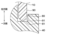
第4実施形態に係る空調装置について図8を用いて説明する。本実施形態の空調装置は、凸部90の先端に、筒状部41の一端側に向かって突出する凸部側突起部91が形成されている。凸部側突起部91の先端は尖った形状を成している。また、凸部側突起部91は、筒状部41の全周にわたって延びるように形成されている。そして、凸部側突起部91が弾性変形した状態で溝部80と接触している。凸部側突起部91は、接触抑制部に相当する。
第4実施形態に係る空調装置について図8を用いて説明する。本実施形態の空調装置は、凸部90の先端に、筒状部41の一端側に向かって突出する凸部側突起部91が形成されている。凸部側突起部91の先端は尖った形状を成している。また、凸部側突起部91は、筒状部41の全周にわたって延びるように形成されている。そして、凸部側突起部91が弾性変形した状態で溝部80と接触している。凸部側突起部91は、接触抑制部に相当する。
本実施形態では、上記第1実施形態と共通の構成から奏される同様の効果を上記第1実施形態と同様に得ることができる。
また、上記したように、本実施形態の空調装置は、凸部90の先端に形成され筒状部41の中心軸40a方向の一方側に向かって突出する凸部側突起部91を有している。そして、凸部側突起部91と溝部80とが接触している。
このように、凸部90の先端に形成され筒状部41の中心軸40a方向の一方側に向かって突出する凸部側突起部91により接触抑制部を構成することができる。
(第5実施形態)
第5実施形態に係る空調装置について図9を用いて説明する。本実施形態の空調装置は、凸部90の先端に2つの凸部側突起部91が形成されている。2つの凸部側突起部91の一方は、2つの凸部側突起部91の他方よりも筒状部41の径方向外側に配置されている。そして、2つの凸部側突起部91が弾性変形した状態で溝部80と接触している。2つの凸部側突起部91は、接触抑制部に相当する。
第5実施形態に係る空調装置について図9を用いて説明する。本実施形態の空調装置は、凸部90の先端に2つの凸部側突起部91が形成されている。2つの凸部側突起部91の一方は、2つの凸部側突起部91の他方よりも筒状部41の径方向外側に配置されている。そして、2つの凸部側突起部91が弾性変形した状態で溝部80と接触している。2つの凸部側突起部91は、接触抑制部に相当する。
本実施形態では、上記第1実施形態と共通の構成から奏される同様の効果を上記第1実施形態と同様に得ることができる。
また、上記したように、本実施形態の空調装置は、複数の凸部側突起部91を有し、複数の凸部側突起部91と溝部80とが接触している。
このように、複数の凸部側突起部91により接触抑制部を構成することもできる。これにより、さらに、凸部側突起部91と溝部80とのシール性が確保され、より空調ケース10とモータホルダ40との間の風漏れおよび水漏れを抑制することができ、さらに、磁気音の放射を抑制することもできる。
なお、本実施形態では、2つの凸部側突起部91を備えたが、3つ以上の凸部側突起部91を備えることもできる。
(第6実施形態)
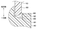
第6実施形態に係る空調装置について図10を用いて説明する。本実施形態の空調装置は、凸部90の先端に、筒状部41の径内方向に進むにつれて凸部90の先端から筒状部41の中心軸40a方向の一方側に向かって傾斜するように突出する凸部側傾斜部92を有している。凸部側傾斜部92は、筒状部41の全周にわたって延びるように形成されている。そして、凸部側傾斜部92が弾性変形した状態で溝部80と接触している。凸部側傾斜部92は、接触抑制部に相当する。
第6実施形態に係る空調装置について図10を用いて説明する。本実施形態の空調装置は、凸部90の先端に、筒状部41の径内方向に進むにつれて凸部90の先端から筒状部41の中心軸40a方向の一方側に向かって傾斜するように突出する凸部側傾斜部92を有している。凸部側傾斜部92は、筒状部41の全周にわたって延びるように形成されている。そして、凸部側傾斜部92が弾性変形した状態で溝部80と接触している。凸部側傾斜部92は、接触抑制部に相当する。
本実施形態では、上記第1実施形態と共通の構成から奏される同様の効果を上記第1実施形態と同様に得ることができる。
また、上記したように、本実施形態の空調装置は、筒状部41の中心軸40aを中心とする径内方向に進むにつれて凸部90の先端から筒状部41の中心軸40a方向の一方側に向かって傾斜するように突出する凸部側傾斜部92を有している。そして、凸部側傾斜部92と溝部80とが接触している。
このように、筒状部41の中心軸40aを中心とする径内方向に進むにつれて凸部90の先端から筒状部41の中心軸40a方向の一方側に向かって傾斜するように突出する凸部側傾斜部92により接触抑制部を構成することができる。
(第7実施形態)
第7実施形態に係る空調装置について図11を用いて説明する。本実施形態の空調装置は、筒状部41の中心軸40aを中心とする径内方向に進むにつれて溝部80の底部81から筒状部41の中心軸40a方向の他方側に向かって傾斜するように突出する溝部側傾斜部83を有している。さらに、空調装置は、筒状部41の中心軸40aを中心とする径内方向に進むにつれて凸部90の先端から筒状部41の中心軸40a方向の一方側に向かって傾斜するように突出する凸部側傾斜部92を有している。そして、溝部側傾斜部83と凸部側傾斜部92とが弾性変形した状態で接触している。溝部側傾斜部83および凸部側傾斜部92は、接触抑制部に相当する。
第7実施形態に係る空調装置について図11を用いて説明する。本実施形態の空調装置は、筒状部41の中心軸40aを中心とする径内方向に進むにつれて溝部80の底部81から筒状部41の中心軸40a方向の他方側に向かって傾斜するように突出する溝部側傾斜部83を有している。さらに、空調装置は、筒状部41の中心軸40aを中心とする径内方向に進むにつれて凸部90の先端から筒状部41の中心軸40a方向の一方側に向かって傾斜するように突出する凸部側傾斜部92を有している。そして、溝部側傾斜部83と凸部側傾斜部92とが弾性変形した状態で接触している。溝部側傾斜部83および凸部側傾斜部92は、接触抑制部に相当する。
本実施形態では、上記第1実施形態と共通の構成から奏される同様の効果を上記第1実施形態と同様に得ることができる。
また、上記したように、溝部側傾斜部83および凸部側傾斜部92により接触抑制部を構成することができる。
(第8実施形態)
第8実施形態に係る空調装置について図12を用いて説明する。本実施形態の空調装置は、筒状部41の中心軸40aを中心とする径外方向に進むにつれて溝部80の底部81から筒状部41の中心軸40a方向の他方側に向かって傾斜するように突出する溝部側傾斜部83を有している。また、空調装置は、筒状部41の中心軸40aを中心とする径外方向に進むにつれて凸部90の先端から筒状部41の中心軸40a方向の一方側に向かって傾斜するように突出する凸部側傾斜部92と、を有している。そして、溝部側傾斜部83と凸部側傾斜部92とが弾性変形した状態で接触している。溝部側傾斜部83および凸部側傾斜部92は、接触抑制部に相当する。
第8実施形態に係る空調装置について図12を用いて説明する。本実施形態の空調装置は、筒状部41の中心軸40aを中心とする径外方向に進むにつれて溝部80の底部81から筒状部41の中心軸40a方向の他方側に向かって傾斜するように突出する溝部側傾斜部83を有している。また、空調装置は、筒状部41の中心軸40aを中心とする径外方向に進むにつれて凸部90の先端から筒状部41の中心軸40a方向の一方側に向かって傾斜するように突出する凸部側傾斜部92と、を有している。そして、溝部側傾斜部83と凸部側傾斜部92とが弾性変形した状態で接触している。溝部側傾斜部83および凸部側傾斜部92は、接触抑制部に相当する。
本実施形態では、上記第1実施形態と共通の構成から奏される同様の効果を上記第1実施形態と同様に得ることができる。
また、上記したように、溝部側傾斜部83および凸部側傾斜部92により接触抑制部を構成することができる。
(他の実施形態)
(1)上記第3実施形態では、溝部側傾斜部83が、筒状部41の径内方向に進むにつれて溝部80の底部81から筒状部41の中心軸40a方向の他方側に向かって傾斜するように突出するよう形成されている。これに対し、溝部側傾斜部83が、筒状部41の径外方向に進むにつれて溝部80の底部81から筒状部41の中心軸方向の他方側に向かって傾斜するように突出するよう形成してもよい。
(1)上記第3実施形態では、溝部側傾斜部83が、筒状部41の径内方向に進むにつれて溝部80の底部81から筒状部41の中心軸40a方向の他方側に向かって傾斜するように突出するよう形成されている。これに対し、溝部側傾斜部83が、筒状部41の径外方向に進むにつれて溝部80の底部81から筒状部41の中心軸方向の他方側に向かって傾斜するように突出するよう形成してもよい。
(2)上記第6実施形態では、凸部側傾斜部92が、筒状部41の径内方向に進むにつれて凸部90の先端から筒状部41の中心軸方向の他方側に向かって傾斜するように突出するよう形成されている。これに対し、凸部側傾斜部92が、筒状部41の径外方向に進むにつれて凸部90の先端から筒状部41の中心軸方向の他方側に向かって傾斜するように突出するよう形成してもよい。
(3)上記第7実施形態では、溝部側傾斜部83が、筒状部41の径内方向に進むにつれて溝部80の底部81から筒状部41の中心軸方向の他方側に向かって傾斜するように突出するよう形成されている。さらに、凸部側傾斜部92が、筒状部41の径内方向に進むにつれて凸部の先端から筒状部41の中心軸40a方向の他方側に向かって傾斜するように突出するよう形成されている。
これに対し、筒状部41の径外方向に進むにつれて溝部80の底部81から筒状部41の中心軸方向の他方側に向かって傾斜するように突出する溝部側傾斜部83と、筒状部41の径外方向に進むにつれて凸部の先端からモータホルダの中心軸方向の他方側に向かって傾斜するように突出する凸部側傾斜部92を備えた構成とすることもできる。
(4)上記各実施形態では、接触抑制部82~83、91~92が弾性変形して溝部80と凸部90とが嵌合するよう構成されている。これに対し、接触抑制部82~83、91~92が塑性変形して溝部80と凸部90とが嵌合するよう構成することもできる。
なお、本開示は上記した実施形態に限定されるものではなく、適宜変更が可能である。また、上記各実施形態は、互いに無関係なものではなく、組み合わせが明らかに不可な場合を除き、適宜組み合わせが可能である。また、上記各実施形態において、実施形態を構成する要素は、特に必須であると明示した場合および原理的に明らかに必須であると考えられる場合等を除き、必ずしも必須のものではないことは言うまでもない。また、上記各実施形態において、実施形態の構成要素の個数、数値、量、範囲等の数値が言及されている場合、特に必須であると明示した場合および原理的に明らかに特定の数に限定される場合等を除き、その特定の数に限定されるものではない。また、上記各実施形態において、構成要素等の材質、形状、位置関係等に言及するときは、特に明示した場合および原理的に特定の材質、形状、位置関係等に限定される場合等を除き、その材質、形状、位置関係等に限定されるものではない。
(まとめ)
上記各実施形態の一部または全部で示された第1の観点によれば、空調装置は、車室内の空気調和を行う空調装置であって、車室内に送風される空気が流れる通風路を形成する空調ケースと、を備えている。さらに、通風路に空気の流れを発生させるファンと、ファンを回転させるモータと、モータを収容する円筒状の筒状部を有するモータホルダと、を備えている。また、筒状部の外周面には、筒状部の中心軸方向の一方側に凹むとともに筒状部の周方向に延びる溝部を形成する溝形成部が設けられている。また、空調ケースには、筒状部の中心軸方向の一方側に突出するとともに筒状部の円周方向に延びる凸部が設けられている。そして、溝部および凸部の少なくとも一方には、溝部および凸部の接触面積を抑制する接触抑制部が設けられている。この接触抑制部により、溝部と凸部の接触面積が、凸部のうち溝部よりも筒状部の中心軸方向の他方側に位置する部位における中心軸に直交する断面積よりも小さくなるとともに、接触抑制部が変形して溝部と凸部とが嵌合している。
上記各実施形態の一部または全部で示された第1の観点によれば、空調装置は、車室内の空気調和を行う空調装置であって、車室内に送風される空気が流れる通風路を形成する空調ケースと、を備えている。さらに、通風路に空気の流れを発生させるファンと、ファンを回転させるモータと、モータを収容する円筒状の筒状部を有するモータホルダと、を備えている。また、筒状部の外周面には、筒状部の中心軸方向の一方側に凹むとともに筒状部の周方向に延びる溝部を形成する溝形成部が設けられている。また、空調ケースには、筒状部の中心軸方向の一方側に突出するとともに筒状部の円周方向に延びる凸部が設けられている。そして、溝部および凸部の少なくとも一方には、溝部および凸部の接触面積を抑制する接触抑制部が設けられている。この接触抑制部により、溝部と凸部の接触面積が、凸部のうち溝部よりも筒状部の中心軸方向の他方側に位置する部位における中心軸に直交する断面積よりも小さくなるとともに、接触抑制部が変形して溝部と凸部とが嵌合している。
また、第2の観点によれば、接触抑制部は、溝部の底部から中心軸方向の他方側に向かって突出する溝部側突起部を有し、溝部側突起部と凸部とが接触している。
このように、溝部の底部から中心軸方向の他方側に向かって突出する溝部側突起部により接触抑制部を構成することができる。
また、第3の観点によれば、接触抑制部は、複数の溝部側突起部を有し、複数の溝部側突起部と凸部とが接触している。
このように、複数の溝部側突起部により接触抑制部を構成することで、さらに、空調ケースとモータホルダとの間の風漏れおよび水漏れをより抑制するとともに、モータから放射される磁気音を低減することができる。
また、第4の観点によれば、接触抑制部は、筒状部の中心軸を中心とする径外方向または径内方向に進むにつれて溝部の底部から筒状部の中心軸方向の他方側に向かって傾斜するように突出する溝部側傾斜部を有し、溝部側傾斜部と凸部とが接触している。
このように、筒状部の中心軸を中心とする径外方向または径内方向に進むにつれて溝部の底部から筒状部の中心軸方向の他方側に向かって傾斜するように突出する溝部側傾斜部により接触抑制部を構成することもできる。
また、第5の観点によれば、接触抑制部は、凸部の先端から筒状部の中心軸方向の一方側に向かって突出する凸部側突起部を有し、凸部側突起部と溝部とが接触している。
このように、凸部の先端から筒状部の中心軸方向の一方側に向かって突出する凸部側突起部により接触抑制部を構成することもできる。
また、第6の観点によれば、接触抑制部は、複数の凸部側突起部を有し、複数の凸部側突起部と溝部とが接触している。
このように、複数の凸部側突起部により接触抑制部を構成することで、さらに、空調ケースとモータホルダとの間の風漏れおよび水漏れをより抑制するとともに、モータから放射される磁気音を低減することができる。
また、第7の観点によれば、接触抑制部は、筒状部の中心軸を中心とする径外方向または径内方向に進むにつれて凸部の先端からモータホルダの中心軸方向の他方側に向かって傾斜するように突出する凸部側傾斜部を有し、凸部側傾斜部と溝部とが接触している。
このように、中心軸を中心とする径外方向または径内方向に進むにつれて凸部の先端からモータホルダの中心軸方向の他方側に向かって傾斜するように突出する凸部側傾斜部により接触抑制部を構成することもできる。
また、第8の観点によれば、接触抑制部は、筒状部の中心軸を中心とする径内方向に進むにつれて溝部の底部から中心軸方向の他方側に向かって傾斜するように突出する溝部側傾斜部を有している。さらに、中心軸を中心とする径内方向に進むにつれて凸部の先端から中心軸方向の一方側に向かって傾斜するように突出する凸部側傾斜部を有している。そして、溝部側傾斜部と凸部側傾斜部とが接触している。
このような、溝部側傾斜部と凸部側傾斜部とにより接触抑制部を構成することもできる。
また、第9の観点によれば、接触抑制部は、中心軸を中心とする径外方向に進むにつれて溝部の底部から中心軸方向の他方側に向かって傾斜するように突出する溝部側傾斜部を有している。また、中心軸を中心とする径外方向に進むにつれて凸部の先端から中心軸方向の一方側に向かって傾斜するように突出する凸部側傾斜部を有している。そして、溝部側傾斜部と凸部側傾斜部とが接触している。
このような、溝部側傾斜部と凸部側傾斜部とにより接触抑制部を構成することもできる。
なお、溝部側突起部82、溝部側傾斜部83、凸部側突起部91、凸部側傾斜部92が接触抑制部に相当する。
Claims (9)
- 車室内の空気調和を行う空調装置であって、
前記車室内に送風される空気が流れる通風路(11)を形成する空調ケース(10)と、
前記通風路に前記空気の流れを発生させるファン(20)と、
前記ファンを回転させるモータ(30)と、
前記モータを収容する円筒状の筒状部(41)を有するモータホルダ(40)と、を備え、
前記筒状部の外周面には、前記筒状部の中心軸(40a)方向の一方側に凹むとともに前記筒状部の周方向に延びる溝部(80)を形成する溝形成部(84)が設けられ、
前記空調ケースには、前記筒状部の中心軸方向の一方側に突出するとともに前記筒状部の円周方向に延びる凸部(90)が設けられ、
前記溝部および前記凸部の少なくとも一方には、前記溝部および前記凸部の接触面積を抑制する接触抑制部(82~83、91~92)が設けられており、
前記接触抑制部により、前記溝部と前記凸部の接触面積が、前記凸部のうち前記溝部よりも前記筒状部の中心軸方向の他方側に位置する部位における前記中心軸に直交する断面積よりも小さくなるとともに、前記接触抑制部が変形して前記溝部と前記凸部とが嵌合している空調装置。 - 前記接触抑制部は、前記溝部の底部から前記筒状部の中心軸方向の他方側に向かって突出する溝部側突起部(82)を有し、
前記溝部側突起部と前記凸部とが接触している請求項1に記載の空調装置。 - 前記接触抑制部は、複数の前記溝部側突起部を有し、
複数の前記溝部側突起部と前記凸部とが接触している請求項2に記載の空調装置。 - 前記接触抑制部は、前記筒状部の中心軸を中心とする径外方向または径内方向に進むにつれて前記溝部の底部から前記筒状部の中心軸方向の他方側に向かって傾斜するように突出する溝部側傾斜部(83)を有し、
前記溝部側傾斜部と前記凸部とが接触している請求項1に記載の空調装置。 - 前記接触抑制部は、前記凸部の先端から前記筒状部の中心軸方向の一方側に向かって突出する凸部側突起部(91)を有し、
前記凸部側突起部と前記溝部とが接触している請求項1に記載の空調装置。 - 前記接触抑制部は、複数の前記凸部側突起部を有し、
複数の前記凸部側突起部と前記溝部とが接触している請求項5に記載の空調装置。 - 前記接触抑制部は、前記筒状部の中心軸を中心とする径外方向または径内方向に進むにつれて前記凸部の先端から前記筒状部の中心軸方向の一方側に向かって傾斜するように突出する凸部側傾斜部(92)を有し、
前記凸部側傾斜部と前記溝部とが接触している請求項1に記載の空調装置。 - 前記接触抑制部は、
前記筒状部の中心軸を中心とする径内方向に進むにつれて前記溝部の底部から前記筒状部の中心軸方向の他方側に向かって傾斜するように突出する溝部側傾斜部(83)と、
前記筒状部の中心軸を中心とする径内方向に進むにつれて前記凸部の先端から前記筒状部の中心軸方向の一方側に向かって傾斜するように突出する凸部側傾斜部(92)と、を有し、
前記溝部側傾斜部と前記凸部側傾斜部とが接触している請求項2に記載の空調装置。 - 前記接触抑制部は、
前記筒状部の中心軸を中心とする径外方向に進むにつれて前記溝部の底部から前記筒状部の中心軸方向の他方側に向かって傾斜するように突出する溝部側傾斜部(83)と、
前記筒状部の中心軸を中心とする径外方向に進むにつれて前記凸部の先端から前記筒状部の中心軸方向の一方側に向かって傾斜するように突出する凸部側傾斜部(92)と、を有し、
前記溝部側傾斜部と前記凸部側傾斜部とが接触している請求項2に記載の空調装置。
Applications Claiming Priority (2)
| Application Number | Priority Date | Filing Date | Title |
|---|---|---|---|
| JP2018-128136 | 2018-07-05 | ||
| JP2018128136A JP2020006766A (ja) | 2018-07-05 | 2018-07-05 | 空調装置 |
Publications (1)
| Publication Number | Publication Date |
|---|---|
| WO2020009196A1 true WO2020009196A1 (ja) | 2020-01-09 |
Family
ID=69059247
Family Applications (1)
| Application Number | Title | Priority Date | Filing Date |
|---|---|---|---|
| PCT/JP2019/026693 Ceased WO2020009196A1 (ja) | 2018-07-05 | 2019-07-04 | 空調装置 |
Country Status (2)
| Country | Link |
|---|---|
| JP (1) | JP2020006766A (ja) |
| WO (1) | WO2020009196A1 (ja) |
Citations (6)
| Publication number | Priority date | Publication date | Assignee | Title |
|---|---|---|---|---|
| JPH02118448U (ja) * | 1989-03-13 | 1990-09-21 | ||
| JPH0629363U (ja) * | 1992-08-31 | 1994-04-15 | アスモ株式会社 | モータ減速部の防水構造 |
| JPH0958719A (ja) * | 1995-08-18 | 1997-03-04 | Ishizuka Glass Co Ltd | 壜口と合成樹脂キャップの組合せ構造 |
| JP2003080922A (ja) * | 2001-06-25 | 2003-03-19 | Calsonic Kansei Corp | モータの取付構造 |
| US20030210981A1 (en) * | 2002-05-10 | 2003-11-13 | Halla Climate Control Corporation | Blower unit for air conditioner |
| JP2019018784A (ja) * | 2017-07-20 | 2019-02-07 | 株式会社Soken | 空調装置 |
-
2018
- 2018-07-05 JP JP2018128136A patent/JP2020006766A/ja active Pending
-
2019
- 2019-07-04 WO PCT/JP2019/026693 patent/WO2020009196A1/ja not_active Ceased
Patent Citations (6)
| Publication number | Priority date | Publication date | Assignee | Title |
|---|---|---|---|---|
| JPH02118448U (ja) * | 1989-03-13 | 1990-09-21 | ||
| JPH0629363U (ja) * | 1992-08-31 | 1994-04-15 | アスモ株式会社 | モータ減速部の防水構造 |
| JPH0958719A (ja) * | 1995-08-18 | 1997-03-04 | Ishizuka Glass Co Ltd | 壜口と合成樹脂キャップの組合せ構造 |
| JP2003080922A (ja) * | 2001-06-25 | 2003-03-19 | Calsonic Kansei Corp | モータの取付構造 |
| US20030210981A1 (en) * | 2002-05-10 | 2003-11-13 | Halla Climate Control Corporation | Blower unit for air conditioner |
| JP2019018784A (ja) * | 2017-07-20 | 2019-02-07 | 株式会社Soken | 空調装置 |
Also Published As
| Publication number | Publication date |
|---|---|
| JP2020006766A (ja) | 2020-01-16 |
Similar Documents
| Publication | Publication Date | Title |
|---|---|---|
| US9844997B2 (en) | Air conditioner for vehicle | |
| WO2019031151A1 (ja) | 送風機 | |
| WO2023182316A1 (ja) | 空調装置 | |
| KR101692225B1 (ko) | 차량용 공조장치 | |
| JP6053851B2 (ja) | 車両用空調装置 | |
| WO2020009196A1 (ja) | 空調装置 | |
| KR20150132633A (ko) | 차량용 공조장치 | |
| JP2000127740A (ja) | 遠心送風機 | |
| JP6608678B2 (ja) | 車両用空調装置 | |
| WO2018151149A1 (ja) | 車両用空調装置 | |
| JP2020011694A (ja) | 空調装置 | |
| JP5462670B2 (ja) | 車両用空調装置 | |
| JP2020018041A (ja) | 空調装置 | |
| WO2019017140A1 (ja) | 空調装置 | |
| JP2018001820A (ja) | 送風ユニット | |
| JP2020018040A (ja) | 空調装置 | |
| WO2019176390A1 (ja) | 空調装置 | |
| WO2019188367A1 (ja) | 車両空調用送風装置 | |
| JP2023143664A (ja) | 空調装置 | |
| WO2019017141A1 (ja) | 空調装置 | |
| JP2020018039A (ja) | 空調装置 | |
| JP2010019078A (ja) | 送風機 | |
| JP2014118054A (ja) | 車両用空調装置 | |
| JP2023131496A (ja) | ロータリドアおよび空調装置 | |
| JP2004216982A (ja) | 空調装置用送風ダクト |
Legal Events
| Date | Code | Title | Description |
|---|---|---|---|
| 121 | Ep: the epo has been informed by wipo that ep was designated in this application |
Ref document number: 19830424 Country of ref document: EP Kind code of ref document: A1 |
|
| NENP | Non-entry into the national phase |
Ref country code: DE |
|
| 122 | Ep: pct application non-entry in european phase |
Ref document number: 19830424 Country of ref document: EP Kind code of ref document: A1 |