WO2020009085A1 - Actionneur de caméra, module de caméra, et dispositif de montage de caméra - Google Patents
Actionneur de caméra, module de caméra, et dispositif de montage de caméra Download PDFInfo
- Publication number
- WO2020009085A1 WO2020009085A1 PCT/JP2019/026209 JP2019026209W WO2020009085A1 WO 2020009085 A1 WO2020009085 A1 WO 2020009085A1 JP 2019026209 W JP2019026209 W JP 2019026209W WO 2020009085 A1 WO2020009085 A1 WO 2020009085A1
- Authority
- WO
- WIPO (PCT)
- Prior art keywords
- actuator
- camera
- ois
- coil
- magnet
- Prior art date
Links
Images


Classifications
-
- G—PHYSICS
- G02—OPTICS
- G02B—OPTICAL ELEMENTS, SYSTEMS OR APPARATUS
- G02B7/00—Mountings, adjusting means, or light-tight connections, for optical elements
- G02B7/02—Mountings, adjusting means, or light-tight connections, for optical elements for lenses
- G02B7/04—Mountings, adjusting means, or light-tight connections, for optical elements for lenses with mechanism for focusing or varying magnification
-
- G—PHYSICS
- G03—PHOTOGRAPHY; CINEMATOGRAPHY; ANALOGOUS TECHNIQUES USING WAVES OTHER THAN OPTICAL WAVES; ELECTROGRAPHY; HOLOGRAPHY
- G03B—APPARATUS OR ARRANGEMENTS FOR TAKING PHOTOGRAPHS OR FOR PROJECTING OR VIEWING THEM; APPARATUS OR ARRANGEMENTS EMPLOYING ANALOGOUS TECHNIQUES USING WAVES OTHER THAN OPTICAL WAVES; ACCESSORIES THEREFOR
- G03B17/00—Details of cameras or camera bodies; Accessories therefor
- G03B17/02—Bodies
-
- G—PHYSICS
- G03—PHOTOGRAPHY; CINEMATOGRAPHY; ANALOGOUS TECHNIQUES USING WAVES OTHER THAN OPTICAL WAVES; ELECTROGRAPHY; HOLOGRAPHY
- G03B—APPARATUS OR ARRANGEMENTS FOR TAKING PHOTOGRAPHS OR FOR PROJECTING OR VIEWING THEM; APPARATUS OR ARRANGEMENTS EMPLOYING ANALOGOUS TECHNIQUES USING WAVES OTHER THAN OPTICAL WAVES; ACCESSORIES THEREFOR
- G03B5/00—Adjustment of optical system relative to image or object surface other than for focusing
-
- H—ELECTRICITY
- H02—GENERATION; CONVERSION OR DISTRIBUTION OF ELECTRIC POWER
- H02K—DYNAMO-ELECTRIC MACHINES
- H02K33/00—Motors with reciprocating, oscillating or vibrating magnet, armature or coil system
- H02K33/02—Motors with reciprocating, oscillating or vibrating magnet, armature or coil system with armatures moved one way by energisation of a single coil system and returned by mechanical force, e.g. by springs
-
- H—ELECTRICITY
- H04—ELECTRIC COMMUNICATION TECHNIQUE
- H04N—PICTORIAL COMMUNICATION, e.g. TELEVISION
- H04N23/00—Cameras or camera modules comprising electronic image sensors; Control thereof
Definitions
- the present invention relates to a camera actuator, a camera module, and a camera mounting device.
- the camera module includes a lens unit having one or more lenses, and an image sensor that captures a subject image formed by the lens unit.
- a bending optical system that bends light from a subject along the first optical axis in the direction of the second optical axis and guides the light to the subsequent lens unit by a prism that is an optical path bending member provided at the front stage of the lens unit.
- a camera module including (for example, Patent Document 1).
- the camera module disclosed in Patent Literature 1 includes a shake correction device that corrects camera shake that occurs in a camera, and an autofocus device that performs autofocus.
- a camera module has a shake correction actuator and an autofocus actuator as camera actuators.
- the shake correcting actuator includes a first actuator and a second actuator that swing the prism about two different axes. When a camera shake occurs in the camera, the shake correction actuator swings the prism under the control of the control unit to perform the shake correction. As a result, camera shake caused by the camera is corrected.
- the movable-side member holding the prism is directly supported by the fixed-side member in a swingable state. For this reason, for example, when an impact is applied to a camera mounting device on which a camera actuator is mounted, the impact may be transmitted from the fixed member to the movable member, and the movable member may be easily damaged. If such damage occurs in the movable member, the accuracy of the above-described shake correction may be reduced.
- An object of the present invention is to provide a camera actuator, a camera module, and a camera mounting device that can reduce an impact transmitted from a fixed member to a movable member.
- One aspect of the camera actuator according to the present invention includes a fixed member, an optical path bending member that bends incident light along a first direction in a second direction, a movable member that holds the optical path bending member, and a fixed member.
- a first actuator for swinging the movable member about a swing center axis perpendicular to the first direction and the second direction, and an elastic support for elastically supporting the movable member relative to the fixed member.
- a first fixing portion fixed to the movable member at a position corresponding to the position of the swing center axis, and fixed at a position separated from each other with the position of the swing center axis therebetween.
- the vehicle includes a pair of second fixing portions fixed to the side member, and a connecting portion extending from the pair of second fixing portions toward the position of the swing center axis and connecting to the first fixing portion.
- One embodiment of the camera module according to the present invention includes the above-described camera actuator and an imaging element arranged at a stage subsequent to the lens unit.
- One embodiment of a camera-mounted device includes the above-described camera module and a control unit that controls the camera module.
- a camera actuator capable of reducing an impact transmitted from a fixed member to a movable member.
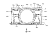
- FIG. 1A is a front view of the camera module according to Embodiment 1 of the present invention.
- FIG. 1B is a rear view of the camera module according to the first embodiment.
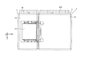
- FIG. 1C is a plan view of the camera module according to the first embodiment.
- FIG. 1D is a bottom view of the camera module according to the first embodiment.
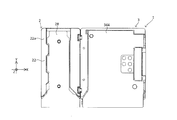
- FIG. 1E is a right side view of the camera module according to Embodiment 1 of the present invention.
- FIG. 1F is a left side view of the camera module according to Embodiment 1 of the present invention.
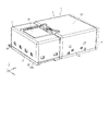
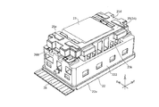
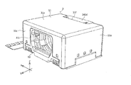
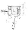
- FIG. 2 is a perspective view of the camera module according to the embodiment of the present invention.
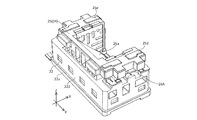
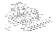
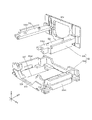
- FIG. 3 is a perspective view showing the prism module of the camera module with some members omitted.
- FIG. 4 is a perspective view showing a prism module in which some members are omitted when viewed from a different angle from FIG.
- FIG. 5 is a perspective view of a state where the holder is assembled to the first base.
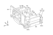
- FIG. 6 is a perspective view of the first base.
- FIG. 7 is a plan view of the first base.
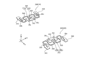
- FIG. 8 is a perspective view showing only the swing support spring.
- FIG. 9 is a sectional view of the prism module.
- FIG. 10 is a perspective view of the holder.
- FIG. 11 is a bottom view of the holder.
- FIG. 12 is an enlarged side view of a portion P in FIG.
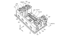
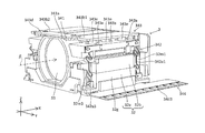
- FIG. 13A is a perspective view of the lens module.
- FIG. 13B is a perspective view of the lens module viewed from a different angle from FIG.
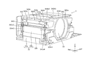
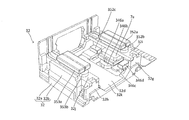
- FIG. 13C is a perspective view of the lens module in which some members are omitted.
- FIG. 14 is a perspective view showing a lens module in which some members are omitted when viewed from a different angle from FIG. 13C.
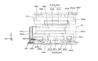
- FIG. 15 is a side view of the lens module from which the second base is omitted.
- FIG. 16 is a side view showing the lens module from which the second base is omitted when viewed from the opposite side to FIG.
- Figure 17 is a lens module that omit some members are A 1 arrow view of FIG. 15.
- FIG. 18 is a perspective view showing the spring taken out in an assembled state.
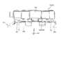
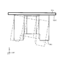
- FIG. 19 is a perspective view of the FPC, the AF actuator, and the rear OIS actuator.
- FIG. 19 is a perspective view of the FPC, the AF actuator, and the rear OIS actuator.
- FIG. 20 is a perspective view of the FPC, the AF actuator, and the rear OIS actuator viewed from a different angle from FIG.
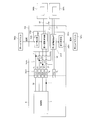
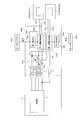
- FIG. 21 is a circuit diagram of the AF drive control circuit.
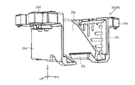
- FIG. 22 is a perspective view of the second base.
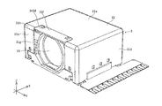
- FIG. 23 is a perspective view of the second base viewed from a different angle from FIG.
- FIG. 24 is an exploded perspective view of the second base.
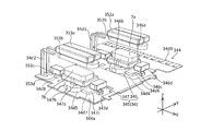
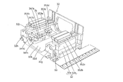
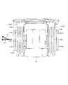
- FIG. 25 is a perspective view of the second base, the AF actuator, and the rear OIS actuator.
- FIG. 26 is a perspective view of the second base, the AF actuator, and the rear OIS actuator, as viewed from a different angle from FIG.
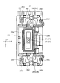
- FIG. 27 is a plan view of the lens module in which some members are omitted.
- FIG. 28 is a schematic plan view of the lens guide and the reference member.
- FIG. 29 is a plan view showing the lens module according to the second embodiment in a state where a part is omitted.
- FIG. 30 is a circuit diagram of the OIS drive control circuit.
- FIG. 31 is a perspective view showing Modification Example 1 of the lens module.
- FIG. 32A is a front view illustrating an example of a camera-mounted device equipped with a camera module.
- FIG. 32B is a rear view illustrating an example of a camera-mounted device equipped with a camera module.
- FIG. 33A is a front view of an automobile on which the on-vehicle camera module is mounted.
- FIG. 33B is a perspective view of an automobile equipped with the vehicle-mounted camera module.
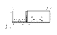
- FIGS. 1A to 28. 1A to 1F are six views showing the appearance (design) of the camera module 1.
- FIG. 1A to 1F are six views showing the appearance (design) of the camera module 1.
- the camera actuator, camera module, and camera mounting device may include all configurations described below or may not include some configurations.
- the camera module 1 includes, for example, a mobile-side camera mounting device such as a smartphone M (see FIGS. 32A and 32B), a mobile phone, a digital camera, a notebook computer, a tablet terminal, and a mobile game machine, and a vehicle-mounted camera. Mounted on camera-mounted devices such as automobiles.
- each part constituting the camera module 1 of the present embodiment will be described based on the state of being incorporated in the camera module 1.
- the rectangular coordinate system (X, Y, Z) shown in each drawing is used.
- the camera module 1 is mounted such that, for example, when an image is actually taken by a camera mounting device, the X direction is the horizontal direction, the Y direction is the vertical direction, and the Z direction is the front and rear direction.
- Light from the subject enters the prism 23 of the prism module 2 from the + side (plus side) in the Z direction, as indicated by a dashed line ⁇ (also referred to as a first optical axis) in FIG.
- the light that has entered the prism 23 bends at an optical path bending surface 231 (see FIG. 9) of the prism 23, as shown by a chain line ⁇ (also referred to as a second optical axis) in FIGS.
- the light is guided to the lens unit 33 (see FIG. 13C) of the lens module 3 disposed downstream of (ie, on the + side in the X direction).
- the subject image formed by the lens unit 33 is captured by the image sensor module 4 (see FIG. 2) disposed downstream of the lens module 3.
- the camera module 1 described above is shake-corrected by a first shake correction device 24 (see FIG. 3) incorporated in the prism module 2 and a second shake correction device 35 (see FIG. 15) incorporated in the lens module 3.
- a first shake correction device 24 see FIG. 3
- a second shake correction device 35 see FIG. 15
- the camera module 1 performs autofocus by displacing the lens unit 33 in the X direction by the AF device 34 (see FIG. 15) incorporated in the lens module 3.
- the prism module 2 will be described with reference to FIGS. 1A to 12.
- the prism module 2 includes a first cover 21, a first base 22, a prism 23, and a first shake correction device 24.
- the first cover 21 is made of, for example, a synthetic resin or a non-magnetic metal, and has a box shape opened on both sides in the Z direction and on the + side in the X direction. Light from the subject side can pass through the opening of the first cover 21 in the + Z direction and enter the internal space of the first cover 21.
- the first cover 21 as described above is combined with a first base 22 described later from the + side in the Z direction.
- the first base 22 will be described with reference to FIGS.
- the first base 22 has a box shape with an opening on the + side in the Z direction and the + side on the X direction.
- the first base 22 has a base-side opening 22b in the bottom wall 22a on the negative side in the Z direction.
- the first coil 27c and the first Hall element 27e of the front OIS actuator 27 are arranged in the base-side opening 22b.
- the first base 22 holds the holder 25 of the first shake correction device 24 via swing support springs 26A and 26B, which will be described later, on a first shaft 29L (also referred to as a swing center axis, which is parallel to the Y direction; see FIG. 6). ) Is supported.
- the first base 22 has a pair of first side walls 220 and 221 that are separated from each other in the Y direction and face each other.
- the first base 22 has a connection wall 222 that connects ends of the pair of first side walls 220 and 221 on the ⁇ side in the X direction.
- the first side walls 220 and 221 each have a first positioning projection 22c and a second positioning projection 22d at both ends in the X direction on the upper surface.
- the first positioning protrusion 22c and the second positioning protrusion 22d respectively engage with a pair of swing support springs 26A, 26B (see FIG. 8) described later to position the pair of swing support springs 26A, 26B. ing.
- the first shake correction device 24 will be described with reference to FIGS.
- the first shake correction device 24 is a first actuator, and swings the prism 23 about a first axis 29L (see FIG. 6) parallel to the Y direction to rotate the prism 23 about the first axis 29L. Is performed.
- Such a first shake correction device 24 is disposed in a first accommodation space 223 (see FIG. 9) covered by the first base 22 and the first cover 21.
- the first shake correction device 24 includes a holder 25, a pair of swing support springs 26A and 26B, a front OIS actuator 27, and the like.
- the holder 25 is supported by the first base 22 via a pair of swing support springs 26A and 26B so as to be displaceable (specifically, swingable). In this state, the holder 25 swings about the first shaft 29L based on the driving force of the front OIS actuator 27 (specifically, the thrust in the X direction).
- the front OIS actuator 27 is driven under the control of the control unit 5 (see FIG. 21)
- the holder 25 and the prism 23 swing about the first shaft 29L. Thereby, the shake in the rotation direction about the first shaft 29L is corrected.
- a specific structure of each member included in the first shake correction device 24 will be described.
- the holder 25 will be described with reference to FIG. 5 and FIGS.
- the holder 25 is made of, for example, a synthetic resin and holds the prism 23.
- the holder 25 and the prism 23 are swingably supported by the first base 22 via a pair of swing support springs 26A and 26B described later.
- the holder 25 includes a mounting surface 25a, a pair of opposing walls 25b and 25c, a pair of overhangs 25d and 25e, and a connection wall 25k.
- the mounting surface 25a faces the optical path bending surface 231 of the prism 23 from the back side (negative side in the Z direction).
- the mounting surface 25a has, for example, a surface parallel to the optical path bending surface 231.
- the mounting surface 25a is not limited to the structure of the present embodiment, and may be, for example, a boss capable of positioning the prism 23.
- the pair of opposing wall portions 25b and 25c are plate members parallel to the XZ plane, and are arranged separated from each other in the Y direction. Such a pair of opposing wall portions 25b and 25c are arranged so as to sandwich the mounting surface 25a from the Y direction.
- a pair of overhang portions 25d and 25e are provided on a pair of opposing wall portions 25b and 25c, respectively. Such a pair of overhang portions 25d and 25e respectively support the holder 25 so as to be swingable with respect to the first base 22.
- one (that is, the + side in the Y direction) protrusion 25d is provided on the + side in the Y direction of the opposing wall 25b, and projects from the side in the + side in the Y direction.
- One (ie, the Y-direction) overhang portion 25e is provided on the Y-direction-side surface of the opposing wall 25c, and projects from the side surface in the Y-direction side. Further, the pair of overhang portions 25d and 25e respectively have flat spring seat surfaces 25f and 25g (see FIG. 11) on the back surface (that is, the surface on the minus side in the Z direction). Each of the spring seat surfaces 25f and 25g has a pair of holder-side positioning projections 25h and 25i (see FIG. 11) protruding in the negative direction in the Z direction at two locations separated in the X direction.
- the surfaces of the first fixing portions 262 of the pair of swing support springs 26A and 26B on the + Z direction side are adhesively fixed to the spring seat surfaces 25f and 25g, respectively.
- the pair of holder-side positioning projections 25h and 25i are inserted into the pair of second through holes 26c of the swing support springs 26A and 26B, respectively.
- the holder 25 is swingably supported with respect to the first base 22.
- connection wall 25k connects the ends of the pair of opposing walls 25b and 25c on the negative side in the X direction in the Y direction.
- the holder 25 has a magnet holding portion 25j (see FIG. 9) for holding a first magnet 27a described later on the back surface.
- ⁇ Swinging support spring> With reference to FIG. 8, a pair of swing support springs 26A and 26B (also referred to as elastic support members) will be described. Each of the pair of swing support springs 26A and 26B elastically supports a holder 25 to be described later with respect to the first base 22. The pair of swing support springs 26A and 26B respectively support the holder 25 so as to be swingable about the first shaft 29L (see FIG. 6) with respect to the first base 22.
- the pair of swing support springs 26A and 26B are metal leaf springs, respectively, and have an upper surface of the first side wall portions 220 and 221 of the first base 22 and a lower surface of the pair of overhang portions 25d and 25e of the holder 25. It is located between.
- the swing support spring 26A of one of the pair of swing support springs 26A and 26B (that is, the Y direction + side) will be described.
- the other swing support spring 26B (that is, the minus side in the Y direction) is symmetric in the Y direction with one swing support spring 26A. For this reason, among the configurations of the swing support spring 26B, the same reference numerals are given to the same configurations as the swing support spring 26A.
- the swing support spring 26A has a first fixing portion 262, a pair of second fixing portions 260 and 261, a pair of connecting portions 263 and 264, and the like.
- One of the pair of second fixing portions 260 and 261 (that is, the + side in the X direction) is disposed at the end of the swing support spring 26A on the + side in the X direction.
- One such second fixing portion 260 has a first through hole 26a.
- the second fixing portion 261 on the other side (that is, on the negative side in the X direction) is arranged at the end on the negative side in the X direction of the swing support spring 26A.
- the other second fixing portion 261 has a first through hole 26b.
- the pair of second fixing portions 260 and 261 are connected to the first fixing portion 262 by a pair of connecting portions 263 and 264 extending in the X direction, respectively.
- the surfaces of the pair of second fixing portions 260 and 261 on the negative side in the Z direction are adhesively fixed to the end surfaces of the first side wall 220 of the first base 22 on the positive side in the Z direction.
- the first positioning protrusions 22c of the first side wall 220 are inserted into the first through holes 26a and 26b, respectively (see FIGS. 6 and 8).
- the surfaces of the pair of second fixing portions 260 and 261 on the negative side in the Z direction are bonded and fixed to the end surfaces of the first side wall 221 of the first base 22 on the positive side in the Z direction. I have.
- the second positioning projection 22d of the first side wall 221 is inserted into each of the first through holes 26a and 26b (see FIGS. 6 and 8).
- the first fixing portion 262 is provided at a portion between the second fixing portions 260 and 261 in the X direction via a gap in the X direction.
- the first fixing portion 262 has a pair of second through holes 26c.
- the surface of the first fixing portion 262 on the + side in the Z direction is adhesively fixed to a spring seat surface 25f formed on the back surface of the extension 25d of the holder 25.
- the surface of the first fixing portion 262 of the swing support spring 26B on the + side in the Z direction is adhesively fixed to a spring seat surface 25g formed on the back surface of the projecting portion 25e of the holder 25.
- a pair of holder-side positioning projections 25h formed on the back surface of the projecting portion 25d of the holder 25 are inserted into the pair of second through holes 26c, respectively.
- a pair of holder-side positioning projections 25i formed on the back surface of the projecting portion 25e of the holder 25 are inserted into the pair of second through holes 26c, respectively.
- the connecting part 263 of the pair of connecting parts 263 and 264 connects the second fixing part 260 and the first fixing part 262.
- the connecting portion 264 of the pair of connecting portions 263 and 264 connects the second fixing portion 261 and the first fixing portion 262.
- Each of the pair of connecting portions 263 and 264 has a substantially S-shaped linear shape.
- the pair of connecting portions 263, 264 are respectively straight portions 26d, 26e parallel to the Y direction (that is, parallel to the first shaft 29L) at ends (also referred to as one ends) on the side closer to the first fixing portion 262. Having.
- the straight portion 26d of the connection portion 263 and the straight portion 26e of the connection portion 264 constitute a torsion allowable portion 265.
- the torsion allowable portion 265 allows the first fixing portion 262 to twist with respect to the second fixing portions 260 and 261 by being twisted. That is, the holder 25 swings with respect to the first base 22 by twisting of the torsion allowance portion 265.
- the first shaft 29L which is the center of the swing of the holder 25, is constituted by the torsion allowable portion 265 of the swing support springs 26A, 26B. Therefore, the holder 25 does not need to include the swing center axis as a configuration. Thus, in the case of the present embodiment, the holder 25 is simply configured.
- the torsion allowable portion 265 allows relative displacement in the Z direction between the second fixing portions 260 and 261 and the first fixing portion 262 by being elastically deformed. That is, the torsion allowable portion 265 allows relative displacement in the Z direction between the first base 22 and the holder 25 by elastically deforming. With such a configuration, the impact transmitted from the first base 22 to the holder 25 is reduced.
- the torsion allowable portion 265 may be provided with a gel-like vibration damping member.
- the vibration damping member may be provided so as to cover the twist allowable portion 265. Further, the vibration damping member may be in contact with the upper surfaces of the first side walls 220 and 221 of the first base 22. Further, the vibration damping member may be in contact with the upper surfaces of the first side walls 220 and 221 of the first base 22 and the lower surfaces of the pair of overhangs 25 d and 25 e of the holder 25.
- the vibration damping member is effective in suppressing resonance of the pair of swing support springs 26A and 26B. From the viewpoint of suppressing the resonance, it is preferable that the vibration damping member is provided in the torsion permissible portion 265 that deforms most when used in the pair of swing support springs 26A and 26B. However, the vibration damping member may be provided at a portion other than the torsion allowable portion 265 of the pair of swing support springs 26A and 26B.
- the holder 25 and the first base 22 are not in direct contact. That is, in the assembled state, the holder 25 and the first base 22 are connected only via the pair of swing support springs 26A and 26B. In other words, the holder 25 and the first base 22 are apart from each other except for the connection between the pair of swing support springs 26A and 26B.
- the damping member is in contact with the first base 22 and the holder 25, the first base 22 and the holder 25 are connected only to the pair of swing support springs 26A and 26B and the damping member. Connected through.
- the peripheral surface of the first base 22 does not contact the peripheral surface of the holder 25 facing the peripheral surface in a predetermined direction.
- the holder 25 is supported (floating supported) so as to float on the first base 22 by the pair of swinging support springs 26A and 26B.
- the entire surface is located between the upper surface of the bottom wall portion 22 a of the first base 22 and the back surface of the holder 25 facing the low wall portion 22 a in the Z direction. There is a predetermined gap in the Z direction.
- the inner side surface (the Y-side surface) of the first side wall 220 of the first base 22 and the outer side surface (the Y-direction side surface) of the opposing wall portion 25b of the holder 25 facing the inner side surface There is a predetermined gap in the Y direction over the entire surface.
- the inner side surface of the first side wall portion 221 of the first base 22 (the + side surface in the Y direction) and the outer side surface of the opposing wall portion 25 c of the holder 25 facing the inner side surface (the ⁇ side surface in the Y direction)
- connection wall portion 222 of the first base 22 (the + side surface in the X direction) and the outer surface of the connection wall portion 25 k of the holder 25 facing the inner surface (the ⁇ side surface in the X direction).
- the upper surfaces of the first side walls 220 and 221 of the first base 22 (the surface on the + side in the Z direction) and the lower surfaces of the pair of protrusions 25d and 25e of the holder 25 facing the upper surface in the Z direction ( ⁇ Z direction). (A side surface), there is a gap in the Z direction over the entire surface.
- the pair of swing support springs 26A and 26B alleviate the impact applied to the holder 25 and the prism 23 from the first base 22. This suppresses damage to the holder 25 when the camera mounting device falls.
- the front OIS actuator 27 (also referred to as a first actuator) will be described with reference to FIGS.
- the front OIS actuator 27 swings the holder 25 about the first shaft 29L (see FIG. 6).
- the first axis 29L is an axis parallel to the Y direction.
- the first shaft 29L is a straight line connecting the center positions in the X direction of the first fixing portions 262 of the pair of swing support springs 26A and 26B.
- the front OIS actuator 27 is disposed on the back side (that is, the negative side in the Z direction) of the prism 23 and the holder 25 so as to overlap the optical path bending surface 231 of the prism 23 and the holder 25 in the Z direction (that is, the direction of the first optical axis). Have been.
- the front OIS actuator 27 includes a first magnet 27a, a first coil 27c, a first Hall element 27e, and the like.
- the first magnet 27a is fixed to the rear side surface (that is, the surface on the negative side in the Z direction) of the holder 25, which is a movable member. Specifically, the first magnet 27a is fixed to a magnet holding portion 25j provided on the back surface of the holder 25.
- the first magnet 27a is composed of two magnet elements adjacent in the X direction. Each of these magnet elements is magnetized in the Z direction, and has one magnetic pole on one side. The directions of the magnetic poles of each magnet element are opposite to each other.
- the first magnet 27a may include two magnet elements integrally formed.
- the first coil 27c and the first Hall element 27e are fixed to the surface of the flexible printed circuit board (hereinafter, referred to as FPC) 28 fixed to the back surface of the first base 22 (that is, the surface on the + side in the Z direction). I have.
- FPC flexible printed circuit board
- the first coil 27c and the first Hall element 27e are arranged in the base-side opening 22b of the first base 22.
- the first coil 27c is a so-called air-core coil having an oval shape. Note that the first coil 27c may be a so-called pattern coil printed on the surface of the FPC 28.
- the first Hall element 27e is arranged inside the first coil 27c in the radial direction.
- the front OIS actuator 27 having the above configuration swings the holder 25 about the first shaft 29L (see FIG. 6) under the control of the control unit 5 (see FIG. 21).
- lens module 3 will be described with reference to FIG. 2 and FIGS. 13A to 28.
- the lens module 3 includes a second cover 31, a second base 32, a lens unit 33, an AF device 34, and a second shake correction device 35.
- the lens module 3 shown in FIGS. 13A to 28 differs from, for example, the lens module 3 shown in FIG. 2 in the direction in which the terminals (such as a first terminal portion 34d1 described later) of the FPC project from the second base 32.
- the structure of the other parts in the lens module 3 shown in FIGS. 13A to 28 is substantially the same as that of the lens module 3 shown in FIG.
- the second cover 31 will be described with reference to FIGS. 2, 13A and 13B.
- the second cover 31 is made of, for example, a synthetic resin or a non-magnetic metal, and has a box shape that is open on both sides in the X direction and on the ⁇ side (that is, the back side) in the Z direction.
- the second cover 31 has a top plate portion 31a, a front plate portion 31b, a rear plate portion 31c, a first side plate portion 31d, and a second side plate portion 31e.
- the top plate portion 31a is a rectangular plate member. Such a top plate portion 31a is disposed on the + side in the Z direction of the second cover 31.
- the top plate portion 31a has a notch 31f at one end in the X direction (an end on the prism module 2 (see FIG. 2) side and an end on the negative side in the X direction).
- the notch 31f is cut out from the minus end in the X direction of the top plate portion 31a toward the plus side in the X direction.
- Such a notch 31f has a rectangular shape long in the Y direction in plan view.
- a connection member 343d described later is arranged in such a notch 31f.
- the front plate portion 31b is a rectangular plate member, and extends from the X-direction end of the top plate portion 31a to the Z-direction side.
- the front plate portion 31b has a front opening portion 31g in a portion including the central portion.
- the front opening 31g has a size such that the end surface on the ⁇ X direction side of the lens unit 33 can be exposed on the ⁇ X direction side.
- Light from the prism module 2 passes through the front opening 31g and enters the lens unit 33.
- the front opening 31g is continuous with the notch 31f of the top plate 31a. Therefore, the edge of the front opening 31g on the + side in the Z direction does not exist in the corner 31h formed by the top plate 31a and the front plate 31b. Such a configuration can facilitate the processing of the front opening 31g.
- the rear plate portion 31c is a rectangular plate member, and extends from the end of the top plate portion 31a on the plus side in the X direction to the minus side in the Z direction.
- the rear plate portion 31c has a rear opening 31i in a portion including the central portion.
- the rear opening 31i has a size such that the end surface of the lens unit 33 on the + side in the X direction can be exposed on the + side in the X direction.
- the light from the lens unit 33 passes through the rear opening 31i and enters the image sensor module 4.
- the first side plate portion 31d is a rectangular plate member, and extends from the end of the top plate portion 31a on the plus side in the Y direction to the minus side in the Z direction.
- the second side plate portion 31e is a rectangular plate member, and extends from the Y-direction end of the top plate portion 31a to the Z-direction side.
- the second cover 31 as described above is combined with a second base 32 described later from the + side in the Z direction.
- the second base 32 will be described with reference to FIGS. 13C, 14, and 22 to 26.
- the second base 32 is combined with the above-described second cover 31 to form a second accommodation space 32c (see FIG. 2) in which the lens unit 33, the AF device 34, and the second shake correction device 35 can be arranged. .
- the second base 32 is configured by combining a lower base element 32a and an upper base element 32b.
- the second base 32 has a bottom surface portion 32d and a pair of second side wall portions 32g, 32h.
- the bottom surface 32d has a base made of a synthetic resin, and a metal reinforcing plate 32k insert-molded on the base. Such a reinforcing plate 32k contributes to increasing the rigidity and reducing the thickness of the bottom surface portion 32d.
- the reinforcing plate 32k of the second base 32 is disposed on the minus side in the Z direction from a lens guide 341 described later so as to overlap the lens guide 341.
- the range in which the lens guide 341 can move during the autofocus operation that is, the range in which the lens guide 341 can move in the X direction
- the range in which the lens guide 341 can move during the shake correction operation that is, the range that can move in the Y direction
- the lens guide 341 exists on the + side in the Z direction of the reinforcing plate 32k. Therefore, the surface of the reinforcing plate 32k (that is, the surface on the + side in the Z direction) is always covered with the lens guide 341 and is not exposed. Thus, the light reflected by the reinforcing plate 32k is prevented from entering the lens unit 33 and eventually the image sensor of the image sensor module 4 described later.
- the second base 32 has bottom through holes 32e and 32f (see FIGS. 22 and 23) on both sides in the Y direction of the reinforcing plate 32k on the bottom surface 32d. As shown in FIGS. 25 and 26, a first AF coil 346b and a second AF coil 347b of an AF actuator 345 described later are arranged in the bottom through holes 32e and 32f, respectively.
- the second side walls 32g and 32h extend from both ends in the Y direction of the bottom surface 32d to the + side in the Z direction.
- the second side wall 32g is formed by combining the second lower wall element 32a1 of the lower base element 32a and the second upper wall element 32b1 of the upper base element 32b. It is configured.
- the second side wall portion 32h is configured by combining a second lower wall element 32a2 of the lower base element 32a and a second upper wall element 32b2 of the upper base element 32b.
- the second side wall portions 32g and 32h have coil mounting portions 32i and 32j, respectively.
- a first OIS coil 352b and a second OIS coil 353b of a second shake correction device 35 described later are mounted on such coil mounting portions 32i and 32j, respectively.
- the coil mounting portions 32i, 32j are provided on the upper surfaces of the second upper wall elements 32b1, 32b2 of the upper base element 32b.
- the coil mounting portion 32i is disposed between the first overhang portion 34a1 and the second overhang portion 34a3 of the lens guide 341 in the Z direction.
- the coil mounting portion 32j is disposed between the first overhang portion 34a2 and the second overhang portion 34a4 of the lens guide 341 in the Z direction.
- a first AF magnet 346a of an AF actuator 345 described below is disposed between the coil mounting portion 32i and the bottom surface 32d. Further, as shown in FIG. 26, a second AF magnet 347a of the AF actuator 345 is disposed between the coil mounting portion 32j and the bottom surface portion 32d. The first AF magnet 346a and the second AF magnet 347a are held by a lens guide 341 described later.
- the bottom surface through holes 32e and 32f and the coil mounting portions 32i and 32j overlap with a predetermined interval in the Z direction. Therefore, the first AF coil 346b and the second AF coil 347b disposed in the bottom through holes 32e and 32f, and the first OIS coil 352b and the second OIS coil 353b mounted on the coil mounting portions 32i and 32j. Overlap at a predetermined interval in the Z direction.
- the second side wall portion 32g has spring arranging portions 32m1 and 32m3 (see FIG. 13C) for arranging springs 342a1 and 342a3 to be described later at both ends in the X direction on the side surface on the + Y side.
- the second side wall portion 32h has spring disposing portions 32m2 and 32m4 (see FIG. 14) for disposing springs 342a2 and 342a4 described later on both ends in the X direction on the negative side surface in the Y direction.
- the second base 32 has a reference portion 32n at the end in the X direction + side.
- the reference portion 32n is a plate member provided at an end of the second base 32 on the + side in the X direction.
- Such a side surface of the reference portion 32n on the + side in the X direction is a reference surface in the X direction of the image sensor module 4 described later.
- the reference portion 32n has a first reference surface 32n1 (see FIG. 23), which is a reference surface in the X direction of a lens guide 341 to be described later, on the negative side surface in the X direction.
- Such a first reference plane 32n1 is also a reference for the later-described calibration.
- the reference portion 32n has a through hole at the center thereof for guiding the light passing through the lens portion 33 to the image sensor module 4.
- Such a reference portion 32n is a member for positioning the image sensor module 4.
- the lens portion 33 is disposed in the second housing space 32c (see FIG. 2) while being held by a lens guide 341 described later.
- a lens unit 33 has a cylindrical lens barrel and one or more lenses held by the lens barrel.
- the lens unit 33 has a telephoto lens group, for example, three times or more optically fixed between an end on the negative side in the X direction of the lens barrel and an end on the positive side in the X direction of the lens barrel. Note that the structure of the lens unit 33 is not limited to the above-described structure.
- the AF device 34 will be described with reference to FIGS. 13C to 21.
- the AF device 34 is a driving unit, and displaces the lens unit 33 in the X direction for the purpose of autofocus.
- the AF device 34 includes a lens guide 341, a first support mechanism 342, a second support mechanism 343, an FPC 344, and an AF actuator 345.
- FIG. 15 is a view of the lens module 3 in a state where some members are omitted, as viewed from the + side in the Y direction.
- FIG. 16 is a view of the lens module 3 in a state where some members are omitted, as viewed from the ⁇ side in the Y direction.
- FIG. 17 is a view of the lens module 3 in a state where the second base 32 is omitted, as viewed from the negative side in the X direction.
- the lens guide 341 has a cylindrical lens holding portion 341a, a pair of first overhang portions 34a1, 34a2, and a pair of second overhang portions 34a3, 34a4. Such a lens guide 341 is arranged in the second accommodation space 32c in a state where displacement in the X direction (that is, the direction of the second optical axis) and the Y direction is possible.
- the lens holding portion 341a has a housing space that can hold the lens barrel.
- a pair of first overhang portions 34a1 and 34a2 are provided so as to extend from two locations on the outer peripheral surface of the cylindrical lens holding portion 341a in directions opposite to each other in the Y direction.
- the pair of second overhang portions 34a3, 34a4 are respectively provided in the Y direction from two locations on the + Z direction side of the pair of first overhang portions 34a1, 34a2 on the outer peripheral surface of the cylindrical lens holding portion 341a. They are provided so as to extend in opposite directions.
- One (Y direction + side) of the first overhang 34a1 and one (Y direction + side) of the second overhang 34a3 overlap in the Z direction via a space 34b1.
- the other (Y-direction side) first overhang portion 34a2 and the other (Y-direction side) second overhang portion 34a4 overlap with each other via the space 34b2 in the Z direction.
- the lens guide 341 includes a first magnet holding portion 34a5 (see FIG. 15) for holding a first AF magnet 346a of an AF actuator 345 described later, and a first magnet holding portion 34a6 (FIG. 16) for holding a second AF magnet 347a. Reference). Specifically, the first magnet holding portions 34a5 and 34a6 are provided on the pair of first overhang portions 34a1 and 34a2, respectively.
- the first magnet holding portions 34a5 and 34a6 are concave portions opened on the negative side in the Z direction. Such first magnet holding portions 34a5 and 34a6 are respectively arranged on the negative side in the Z direction of the pair of coil mounting portions 32i and 32j of the second base 32 (see FIGS. 25 and 26).
- the pair of first magnet holding portions 34a5, 34a6 and the bottom through holes 32e, 32f of the second base 32 are provided on the same straight line parallel to the Z direction.
- the pair of first magnet holding portions 34a5 and 34a6 are provided on the + side in the Z direction with respect to the bottom surface through holes 32e and 32f.
- the lens guide 341 has a second magnet holding portion 34a7 (see FIG. 15) for holding a first OIS magnet 352a of a rear OIS actuator 351 described later.
- the lens guide 341 has a second magnet holding portion 34a8 (see FIG. 16) for holding the second OIS magnet 353a of the rear OIS actuator 351.
- the second magnet holding portions 34a7 and 34a8 are provided on the pair of second overhang portions 34a3 and 34a4, respectively.
- the pair of second magnet holding portions 34a7 and 34a8 are concave portions opened on the negative side in the Z direction.
- the pair of second magnet holding portions 34a7, 34a8 and the coil mounting portions 32i, 32j of the second base 32 are provided on the same straight line parallel to the Z direction.
- the pair of second magnet holding portions 34a7, 34a8 are provided on the + side in the Z direction with respect to the coil mounting portions 32i, 32j.
- the lens guide 341 has a third magnet holder 34b3 (see FIG. 15) near the first magnet holder 34a5 for holding the first X position detection magnet 346d of the AF actuator 345.
- the lens guide 341 has a third magnet holder 34b4 (see FIG. 16) that holds the second X position detection magnet 347d of the AF actuator 345 near the first magnet holder 34a6.
- the third magnet holding portions 34b3, 34b4 are respectively provided on the ⁇ X direction side of the first magnet holding portions 34a5, 34a6 of the pair of first overhang portions 34a1, 34a2. Note that the positions of the third magnet holding units 34b3 and 34b4 are not limited to the above positions as long as they are near the first magnet holding units 34a5 and 34a6.
- the lens guide 341 includes a pair of fourth magnet holding portions 34b5 and 34b6 (see FIGS. 15 and 16) that hold the Y position detection magnets 352c and 353c of the rear OIS actuator 351 near the first magnet holding portions 34a5 and 34a6. ).
- the pair of fourth magnet holding portions 34b5 and 34b6 are respectively provided on the X direction + side of the first magnet holding portions 34a5 and 34a6 among the pair of first overhang portions 34a1 and 34a2. .
- the positions of the pair of fourth magnet holding portions 34b5 and 34b6 are not limited to the above-described positions as long as they are near the first magnet holding portions 34a5 and 34a6.
- the lens guide 341 has a plurality of (six in the present embodiment) ball holding portions 343a (see FIG. 14) for holding a plurality of balls 343e of a second support mechanism 343 described later. Specifically, three of these ball holding portions 343a are provided on the surface of the pair of second overhang portions 34a3, 34a4 on the + side in the Z direction.
- the end surface of the lens guide 341 in the + X direction (hereinafter, referred to as “lens guide-side reference surface”) is the first reference surface 32n1 of the reference portion 32n. Abut.
- the lens guide-side reference surface of the lens guide 341 and the first reference surface 32n1 are flat surfaces parallel to the YZ plane. Therefore, in a state in which the lens guide-side reference surface of the lens guide 341 and the first reference surface 32n1 are in contact with each other (surface contact), the lens guide 341 moves Y in the X direction (that is, the direction of the second optical axis).
- the lens guide 341 is not inclined in the direction and the Z direction (hereinafter, referred to as “the reference state of the lens guide 341”).
- the first support mechanism 342 will be described with reference to FIGS. 13C to 16 and FIG.
- the first support mechanism 342 elastically supports the lens guide 341 on the second base 32 so as to be displaceable with respect to the second base 32.
- Such a first support mechanism 342 is also called an elastic support mechanism.
- the first support mechanism 342 has a plurality of (four in the present embodiment) springs 342a1 to 342a4, each of which is an elastic support member.
- the springs 342a1 to 342a4 elastically support the lens guide 341 on the second base 32.
- the lens unit 33 can be displaced in the X direction and the Y direction with respect to the second base 32.
- the displacement of the lens guide 341 in the Z direction with respect to the second base 32 is restricted to a predetermined range by the first support mechanism 342.
- the predetermined range is a range in which the lens guide 341 can be displaced based on the elastic deformation of the springs 342a1 to 342a4.
- the spring 342a1 supports the end of the lens guide 341 on the + side in the X direction and on the + side in the Y direction on the second base 32 (see FIG. 13C).
- the spring 342a2 supports the end of the lens guide 341 on the X direction + side and the Y direction-side on the second base 32 (see FIG. 14).
- the spring 342a3 supports an end of the lens guide 341 on the negative side in the X direction and on the positive side in the Y direction on the second base 32 (see FIG. 13C).
- the spring 342a4 supports the end of the lens guide 341 on the X direction-side and the Y direction-side on the second base 32 (see FIG. 14).
- each of the springs 342a1 to 342a4 has a first fixing portion 342b, a second fixing portion 342c, and a connection portion 342d.
- FIG. 18 shows the springs 342a1 to 342a4 as they are arranged in the assembled state.
- the first fixing portion 342b is fixed to a lens guide 341 which is a movable member.
- the second fixing portion 342c is fixed to the second base 32, which is a fixed member.
- the connecting portion 342d connects the first fixing portion 342b and the second fixing portion 342c.
- the connection portion 342d is made of, for example, a linear member that is at least partially curved (specifically, bent in a meandering shape).
- each of the connection portions 342d includes a first bent portion 342e and a second bent portion 342f in order from the + side in the Z direction.
- Such springs 342a1 to 342a4 are arranged on the spring arrangement portions 32m1 to 32m4 (see FIGS. 13C and 14) of the second base 32, respectively.
- the first bent portion 342e is a portion bent in a meandering shape, and is provided at one end (the end in the + Z direction) of the connecting portion 342d.
- the first bent portion 342e is elastically deformed in the length direction (Z direction) of the connection portion 342d.
- the position of the first bent portion 342e is not limited to the position of the present embodiment.
- the first bent portion 342e is preferably provided in a half portion on one side of the connection portion 342d (that is, a half portion on the first fixed portion 342b side). Further, it is more preferable that the first bent portion 342e is provided at one end of the connection portion 342d as in the present embodiment.
- each of the first bent portions 342e may be covered with a gel-like vibration damping member.
- the second bent portion 342f is a linear member that is provided at the other end (the end on the negative side in the Z direction) of the connecting portion 342d and is bent in a meandering shape.
- the second bent part 342f is elastically deformed in the length direction (Z direction) of the connection part 342d.
- the displacement of the second bent portion 342f when the lens portion 33 is displaced in the Z direction with respect to the second base 32 is smaller than the displacement of the first bent portion 342e.
- connection portion 342d When the lens portion 33 is displaced in the X direction with respect to the second base 32, the connection portion 342d is displaced so as to swing around the end near the second fixed portion 342c. Accordingly, the farther from the fulcrum (in other words, the closer to the first fixing portion 342b) the connecting portion 342d, the larger the displacement amount when the lens portion 33 is displaced in the X direction with respect to the second base 32.
- the position of the second bent portion 342f is not limited to the position of the present embodiment.
- the second bent portion 342f is preferably provided in a half portion on the other side of the connection portion 342d (that is, a half portion on the second fixed portion 342c side). Further, it is more preferable that the second bent portion 342f is provided at the other end of the connection portion 342d as in the present embodiment.
- the second bent portion 342f may be omitted. That is, the connecting portion 342d may have a configuration having a bent portion only at one place.
- each of the second bent portions 342f may be covered with a gel-like vibration damping member.
- connection portion 342d has directionality in the X direction.
- the spring 342a1 and the spring 342a2 are arranged so as to be in the same direction in the X direction.
- the spring 342a1 and the spring 342a2 are arranged such that at least the connection portions 342d overlap when viewed from the + side in the Y direction, for example.
- the spring 342a3 and the spring 342a4 are arranged so as to be in the same direction in the X direction. In other words, the spring 342a3 and the spring 342a4 are arranged such that at least the connection portion 342d overlaps when viewed from the + side in the Y direction, for example.
- the spring 342a1 and the spring 342a3 are arranged such that the connection portion 342d faces in the same direction in the X direction.
- the spring 342a2 and the spring 342a4 are arranged so that the connecting portion 342d faces in the same direction in the X direction.
- the center of gravity G of the movable side member at the reference position matches or substantially matches with the center of gravity G.
- the movable member refers to the lens guide 341 and each member fixed to the lens guide 341 and displaceable together with the lens guide 341.
- the movable side members include the lens guide 341, the lens unit 33, the first AF magnet 346a and the second AF magnet 347a of the AF actuator 345, and the first OIS of the rear OIS actuator 351. It is configured to include a magnet 352a, a second OIS magnet 353a, and the like.
- the center of each of the springs 342a1 to 342a4 is, for example, the center position in the Z direction and the center position in the X direction of each spring 342a1 to 342a4.
- the reference position of the lens guide 341 refers to a state where the lens guide 341 is not displaced in the X direction by the autofocus function and a state where the lens guide 341 is not displaced in the Y direction by the second shake correction device 35 described later.
- the springs 342a1 to 342a4 as described above are arranged as follows.
- a straight line passing through the center of gravity G and parallel to the direction of the second optical axis that is, the X direction
- L 4 straight line
- the pair of springs 342a1 and 342a2 on the + side in the X direction are and symmetrically with respect to L 4, they are arranged in two distant positions spaced by a predetermined distance in the X-direction positive side from the center of gravity G (right side in FIG. 18).
- X-direction - a pair of springs side 342a3,342a4 is symmetrical with respect to the straight line L 4, and, from the center of gravity G X direction - is disposed on the side above a predetermined distance apart two positions (the left side in FIG. 18) You.
- the intersection between the straight line L 1 and the straight line L 2 coincides with the center of gravity G.
- the second support mechanism 343 will be described with reference to FIGS. 13A to 17.
- the second support mechanism 343 supports the lens guide 341 on the second base 32 such that the lens guide 341 can be displaced in the XY plane with respect to the second base 32.
- the second support mechanism 343 supports the lens guide 341 in a state where displacement in the Z direction with respect to the second base 32 is restricted.
- the second support mechanism 343 supports the lens guide 341 in a state in which the lens guide 341 cannot be displaced in the + Z direction with respect to the second base 32.
- the second support mechanism 343 has a plurality of ball holding portions 343a, a pair of track members 343b1, 343b2, a connection member 343d, and a plurality of balls 343e.
- the plurality of ball holding portions 343a are provided on the surfaces of the second overhang portions 34a3 and 34a4 of the lens guide 341 on the + side in the Z direction.
- three ball holding portions 343a are provided on each of the surfaces on the + Z direction side of the second overhang portions 34a3 and 34a4.
- the pair of track members 343b1 and 343b2 are plate members parallel to the XY plane, for example.
- Each of the pair of track members 343b1 and 343b2 is made of a magnetic metal such as an iron-based alloy.
- the track member 343b1 and the first OIS magnet 352a arranged on the + side in the Y direction are arranged on the same straight line parallel to the Z direction. Further, the track member 343b1 is disposed on the + side in the Z direction with respect to the first OIS magnet 352a.
- the track member 343b2 and the second OIS magnet 353a arranged on the negative side in the Y direction are arranged on the same straight line parallel to the Z direction.
- the track member 343b2 is disposed on the + side in the Z direction with respect to the second OIS magnet 353a.
- the first OIS magnet 352a is attracted in the direction approaching the track member 343b1 (that is, in the Z direction + side) based on its own magnetic force.
- the second OIS magnet 353a is attracted in the direction approaching the track member 343b2 (that is, in the + Z direction) based on its magnetic force.
- Such a force acting between the first OIS magnet 352a and the second OIS magnet 353a and the track members 343b1 and 343b2 is, for example, when the springs 342a1 to 342a4 are omitted (that is, in the embodiment described later). 2), it is possible to float the movable member described above from the fixed member (second base 32).
- the pair of track members 343b1 and 343b2 are on the + Z direction side of the second overhang portions 34a3 and 34a4 of the lens guide 341 and the + Z direction surface of the second overhang portions 34a3 and 34a4, respectively. It is provided in the state facing.
- Each of the pair of track members 343b1 and 343b2 has a flat track surface 343c (see FIGS. 15 and 16) on the negative surface in the Z direction.
- the raceway surface 343c is opposed to the surface on the + Z direction side of the second overhang portions 34a3, 34a4 in the Z direction.
- connection member 343d The ends on the negative side in the X direction of the pair of track members 343b1 and 343b2 are connected by a connection member 343d.
- the connection member 343d is arranged in the notch 31f of the top plate 31a in the second cover 31 (see FIGS. 13A and 13C). In this state, the connection member 343d covers the entire cutout 31f. Accordingly, the connection member 343d prevents light from entering the lens unit 33 from the cutout 31f.
- the connection member 343d is fixed to the second cover 31. Since the second cover 31 is fixed to the second base 32, the connection member 343 d and the pair of track members 343 b 1 and 343 b 2 are fixed to the second base 32 via the second cover 31.
- the plurality of balls 343e are respectively held by the plurality of ball holding units 343a. In this state, the plurality of balls 343e are rotatably disposed between the inner surfaces of the plurality of ball holding portions 343a and the track surfaces 343c of the pair of track members 343b1 and 343b2. . The plurality of balls 343e are in contact with the inner surfaces of the plurality of ball holding portions 343a and the raceway surfaces 343c of the pair of raceway members 343b1, respectively.
- the FPC 344 will be described with reference to FIGS. 19 to 21, FIG. 25, and FIG.
- the FPC 344 is a flexible printed circuit board, and is fixed to the second base 32 (see FIGS. 13C and 14).
- the FPC 344 includes an FPC base portion 344a, a first terminal portion 34d1, a second terminal portion 34d2, a third terminal portion 34d3, a first coil fixing portion 34d4, a second coil fixing portion 34d5, a first controller fixing portion 34d6, and a second controller. It has a fixing section 34d7, a hall element fixing section 34d8, and an AF drive control circuit 344b (see FIG. 21).
- the FPC base 344a is a plate member parallel to the XY plane, and is fixed to the second base 32 (see FIGS. 13C and 14).
- the first terminal portion 34d1 and the second terminal portion 34d2 respectively extend in the Z direction + side from two places separated in the Y direction at the X direction + side end of the FPC base 344a.
- the first terminal 34d1 is electrically connected to the first OIS coil 352b.
- the second terminal 34d2 is electrically connected to the second OIS coil 353b.
- the third terminal portion 34d3 is connected to the sensor substrate 6 (FIG. 21) on which the image sensor module 4 is mounted. As shown in FIG. 21, the third terminal unit 34d3 has a power terminal T1, a ground terminal T2, a data signal terminal T3, a first clock terminal T4, and a second clock terminal T5. In a state where the FPC 344 is connected to the sensor board 6, each terminal of the third terminal portion 34d3 is connected to each corresponding terminal in the board-side circuit 6a of the sensor board 6.
- the first coil fixing portion 34d4 and the second coil fixing portion 34d5 are respectively provided at positions facing the first magnet holding portions 34a5, 34a6 of the lens guide 341 in the Z direction on the + Z direction surface of the FPC base 344a. ing. Specifically, the first coil fixing portion 34d4 and the second coil fixing portion 34d5 are connected to one side (Y direction + side) of the FPC base 344a in the Y direction centering on the second optical axis on the surface in the Z direction + side. ) And the other side in the Y direction ( ⁇ side in the Y direction).
- a first AF coil 346b and a second AF coil 347b are fixed to the first coil fixing portion 34d4 and the second coil fixing portion 34d5, respectively.
- the first coil fixing portion 34d4 and the second coil fixing portion 34d5 are respectively disposed in bottom through holes 32e and 32f of the second base 32 (see FIGS. 22 and 23).
- the first controller fixing part 34d6 and the second controller fixing part 34d7 are provided near the first coil fixing part 34d4 and the second coil fixing part 34d5, respectively, on the surface of the FPC base 344a on the + side in the Z direction. Specifically, the first controller fixing portion 34d6 and the second controller fixing portion 34d7 are respectively more in the X direction than the first coil fixing portion 34d4 and the second coil fixing portion 34d5 on the + Z direction surface of the FPC base 344a. It is provided near the negative side.
- a first AF controller 346c and a second AF controller 347c are fixed to the first controller fixing unit 34d6 and the second controller fixing unit 34d7, respectively.
- the Hall element fixing portion 34d8 is provided at a position facing the fourth magnet holding portion 34b6 (see FIG. 16) of the lens guide 341 in the Z direction on the surface of the FPC base 344a on the + side in the Z direction.
- An OIS Hall element 353d of a rear OIS actuator 351 described later is fixed to the Hall element fixing portion 34d8.
- the AF drive control circuit 344b includes a first power line L1, a second power line L2, a first ground line L3, a second ground line L4, a first data signal line L5, and a second data signal. It has a line L6, a first clock line L7, a second clock line L8, first coil power supply lines L9, L10, and second coil power supply lines L11, L12.
- the first power supply line L1 is a transmission line for a current supplied from the control unit 5 mounted on the sensor board 6 to the first AF controller 346c.
- One end of the first power supply line L1 is connected to the power supply terminal T1 of the third terminal portion 34d3.
- the other end of the first power supply line L1 is connected to an input-side power supply terminal (not shown) of the first AF controller 346c.
- the second power supply line L2 is a transmission line for a current supplied from the control unit 5 mounted on the sensor board 6 to the second AF controller 347c.
- One end of the second power supply line L2 is connected to the power supply terminal T1 of the third terminal portion 34d3.
- the other end of the second power line L2 is connected to a power input terminal (not shown) of the second AF controller 347c.
- the first power supply line L1 and the second power supply line L2 are branched on the way.
- the first ground line L3 is a transmission line for ground. One end of the first ground line L3 is connected to the ground terminal T2 of the third terminal portion 34d3. The other end of the first ground line L3 is connected to a ground terminal (not shown) of the first AF controller 346c.
- the second ground line L4 is a transmission line for ground. One end of the second ground line L4 is connected to the ground terminal T2 of the third terminal portion 34d3. The other end of the second ground line L4 is connected to a ground terminal (not shown) of the second AF controller 347c.
- the first ground line L3 and the second ground line L4 are branched on the way.
- the first data signal line L5 is a transmission line for a control signal between the control unit 5 and the first AF controller 346c. One end of the first data signal line L5 is connected to the data signal terminal T3 of the third terminal portion 34d3. The other end of the first data signal line L5 is connected to an input data signal terminal (not shown) of the first AF controller 346c.
- the second data signal line L6 is a control signal transmission line between the control unit 5 and the second AF controller 347c. One end of the second data signal line L6 is connected to the data signal terminal T3 of the third terminal part 34d3. The other end of the second data signal line L6 is connected to an input-side data signal terminal (not shown) of the second AF controller 347c.
- the first data signal line L5 and the second data signal line L6 are branched on the way.
- the first clock line L7 is a transmission line of a clock signal between the control unit 5 and the first AF controller 346c. One end of the first clock line L7 is connected to the first clock terminal T4 of the third terminal 34d3. The other end of the first clock line L7 is connected to a clock terminal (not shown) of the first AF controller 346c.
- the second clock line L8 is a transmission line of a clock signal between the control unit 5 and the second AF controller 347c. One end of the second clock line L8 is connected to the second clock terminal T5 of the third terminal 34d3. The other end of the second clock line L8 is connected to a clock terminal (not shown) of the second AF controller 347c.
- the first coil power supply lines L9 and L10 are transmission lines that connect the first AF controller 346c and the first AF coil 346b.
- One end of the first coil power supply line L9 is connected to a first terminal (not shown) of the output side power supply terminal of the first AF controller 346c.
- the other end of the first coil power supply line L9 is connected to one end of the first AF coil 346b.
- One end of the first coil power supply line L10 is connected to a second terminal (not shown) of the output side power supply terminal of the first AF controller 346c.
- the other end of the first coil power supply line L10 is connected to the other end of the first AF coil 346b.
- the second coil power supply lines L11 and L12 are transmission lines that connect the second AF controller 347c and the second AF coil 347b.
- One end of the second coil power supply line L11 is connected to a first terminal (not shown) of the output side power supply terminal of the second AF controller 347c.
- the other end of the second coil power supply line L11 is connected to one end of the second AF coil 347b.
- One end of the second coil power supply line L12 is connected to a second terminal (not shown) of the output side power supply terminal of the second AF controller 347c.
- the other end of the second coil power supply line L12 is connected to the other end of the second AF coil 347b.
- the AF drive control circuit 344b as described above is connected to the sensor substrate 6 via the third terminal 34d3.
- the first AF controller 346c and the second AF controller 347c are connected to the control unit 5 mounted on the sensor board 6.
- the AF actuator 345 will be described with reference to FIG. 15, FIG. 16, and FIG.
- the AF actuator 345 (also referred to as a third actuator) is a driving mechanism that displaces the lens guide 341 in the X direction (direction of the second optical axis) during autofocus.
- the AF actuator 345 has a first AF actuator 346 disposed on the + side in the Y direction and a second AF actuator 347 disposed on the ⁇ side in the Y direction.
- the first AF actuator 346 is a driving mechanism, and includes a first AF magnet 346a, a first AF coil 346b, a first X position detection magnet 346d, and a first AF controller 346c.
- the second AF actuator 347 is a driving mechanism, and includes a second AF magnet 347a, a second AF coil 347b, a second X position detection magnet 347d, and a second AF controller 347c.
- first AF actuator 346 and a second AF actuator 347 the first AF magnet 346a and the second AF magnet 347a are fixed to the lens guide 341 which is a movable member, and the first AF coil 346b and the The second AF coil 347b is a moving magnet type actuator fixed to the second base 32 which is a fixed side member.
- the first AF actuator 346 and the second AF actuator 347 may be moving coil type actuators.
- the arrangement of each unit constituting the AF actuator 345 will be described.
- each of the first AF magnet 346a and the second AF magnet 347a is composed of two magnet elements (reference numerals are omitted) arranged so as to be adjacent to each other in the Y direction. Each of these magnet elements is magnetized in the Z direction and arranged so that the directions of the magnetic poles are opposite.
- Each of the first AF magnet 346a and the second AF magnet 347a is a rectangular parallelepiped that is long in the X direction and, for example, has a substantially rectangular shape when viewed from the Y direction (the state shown in FIGS. 15 and 16). .
- the first AF coil 346b and the second AF coil 347b are so-called elliptical so-called air-core coils that are supplied with power during auto focus.
- the first AF coil 346b and the second AF coil 347b are fixed to the first coil fixing portion 34d4 and the second coil fixing portion 34d5 of the FPC 344 via a substrate (not shown), respectively, in a state where the long axes are aligned with the Y direction. Have been.
- the first AF coil 346b is connected to the first AF controller 346c via the first coil power supply lines L9 and L10.
- the current value of the first AF coil 346b is controlled by the first AF controller 346c.
- the first X position detection magnet 346d and the second X position detection magnet 347d are magnetized in the Z direction, and are, for example, rectangular parallelepipeds having a substantially rectangular shape when viewed from the Y direction (the state shown in FIGS. 15 and 16). is there. Such a first X position detection magnet 346d and a second X position detection magnet 347d are respectively held by a pair of third magnet holding portions 34b3, 34b4 of the lens guide 341.
- the first AF controller 346c is fixed to the first controller fixing portion 34d6 of the FPC 344. As shown in FIG. 21, such a first AF controller 346c has a first detection unit 346e and a first drive control unit 346f.
- the first detector 346e detects a magnetic flux (also referred to as position information) between the first AF magnet 346a and the first X position detection magnet 346d.
- the first detection unit 346e sends the detection value to the first drive control unit 346f.
- the first drive control unit 346f obtains a position (also referred to as a first position) of the first AF magnet 346a in the X direction based on the detection value received from the first detection unit 346e. Then, the first drive control unit 346f controls the current value of the first AF coil 346b based on the detection value received from the first detection unit 346e. Note that the first AF controller 346c does not control the current value of the second AF coil 347b.
- the closed loop control is performed based on the detection value of the first detection unit 346e.
- the first drive control unit 346f may be omitted.
- the processing performed by the first drive control unit 346f may be performed by, for example, the control unit 5 mounted on the sensor board 6.
- the second AF controller 347c is fixed to the second controller fixing portion 34d7 of the FPC 344. As shown in FIG. 21, the second AF controller 347c includes a second detection unit 347e and a second drive control unit 347f.
- the second detector 347e detects a magnetic flux (also referred to as position information) between the second AF magnet 347a and the second X position detection magnet 347d.
- the second detector 347e sends the detected value to the second drive controller 347f.
- the second drive control unit 347f obtains a position (also referred to as a second position) of the second AF magnet 347a in the X direction based on the detection value (information regarding the position) received from the second detection unit 347e. Further, the second drive control unit 347f controls the current value of the second AF coil 347b based on the detection value received from the second detection unit 347e. Note that the second AF controller 347c does not control the current value of the first AF coil 346b.
- closed loop control is performed based on the detection value of the second AF controller 347c.
- the second drive control unit 347f may be omitted.
- the process performed by the second drive control unit 347f may be performed by, for example, the control unit 5 mounted on the sensor board 6.
- the current is supplied to the first AF coil 346b and the second AF coil 347b under the control of the first AF controller 346c and the second AF controller 347c. Flows, a Lorentz force (thrust) for displacing the first AF magnet 346a and the second AF magnet 347a in the X direction is generated.
- Such thrust is switched by controlling the direction of the current flowing through the first AF coil 346b and the second AF coil 347b. Thereby, the displacement direction of the lens guide 341 can be switched.
- the current value of the first AF coil 346b of the first AF actuator 346 and the current value of the second AF coil 347b of the second AF actuator 347 are controlled independently, so that the first AF The thrust generated by the actuator 346 and the thrust generated by the second AF actuator 347 can be made different.
- the thrust generated by the AF actuator 345 includes only the first thrust in the X direction.
- the thrust generated by the AF actuator 345 is equal to the first thrust in the X direction and the thrust of the movable member.
- a second thrust which is a moment about the center of gravity G.
- the second thrust is a resistance against an external force that tends to cause the lens guide 341 to deviate from the X direction during autofocus. This allows the AF actuator 345 to reduce or eliminate the amount of deviation of the lens guide 341 from the X direction during autofocus.
- the above-mentioned external force will be described later.
- the AF actuator 345 resists an external force acting so as to deviate the movable member (the lens guide 341) from the Y direction when the second shake correction device 35 described later performs shake correction. It is also a second drive mechanism that generates a resistance force.
- the AF actuator 345 controls the first AF magnet 346a and the second AF magnet 347a in the X direction by the first AF controller 346c and the second AF controller 347c. The position at is detected.
- the first AF controller 346c and the second AF controller 347c respectively control the current values of the first AF coil 346b and the second AF coil 347b based on the detected values. Accordingly, when the second shake correction device 35 performs shake correction, the AF actuator 345 generates a resistance to an external force that causes the lens guide 341 to deviate from the Y direction. As a result, the AF actuator 345 can reduce or eliminate the amount of deviation of the lens guide 341 from the Y direction during shake correction.
- the second shake correction device 35 will be described with reference to FIG. 15, FIG. 16, and FIG.
- the second shake correction device 35 is a drive unit, and performs shake correction in the Y direction by displacing the lens unit 33 in the Y direction.
- Such a second shake correction device 35 is disposed in the above-described second accommodation space 32c (see FIG. 2).
- the second shake correction device 35 includes the above-described lens guide 341, the above-described plurality of springs 342a1 to 342a4, the above-described FPC 344, and the rear OIS actuator 351.
- the lens guide 341, the springs 342a1 to 342a4, and the FPC 344 are common to the AF device 34.
- the rear OIS actuator 351 (also referred to as a second actuator) is a driving mechanism, and includes a first OIS actuator 352 disposed on the + side in the Y direction and a second OIS actuator 353 disposed on the ⁇ side in the Y direction. Having.
- the first OIS actuator 352 is a driving mechanism, and is arranged so as to overlap the first AF actuator 346 at a predetermined interval in the Z direction.
- a first OIS actuator 352 has a first OIS magnet 352a, a first OIS coil 352b, and a Y position detection magnet 352c.
- the second OIS actuator 353 is a driving mechanism and is arranged so as to overlap the second AF actuator 347 at a predetermined interval in the Z direction.
- a second OIS actuator 353 has a second OIS magnet 353a, a second OIS coil 353b, a Y position detection magnet 353c, and an OIS Hall element 353d.
- the center of the driving force of the rear OIS actuator 351 is adjusted to the AF actuator 345. To or near the center of the driving force.
- This configuration makes it difficult for the lens guide 341 to undergo tilt displacement (that is, swing displacement about an axis parallel to the Y direction or the Z direction) during autofocus and shake correction.
- the first OIS magnet 352a and the second OIS magnet 353a are fixed to the lens guide 341 which is a movable member, and the first OIS coil 352b and the second OIS coil 353b are fixed.
- the moving magnet type actuator is fixed to the second base 32 as a member.
- the rear OIS actuator 351 may be a moving coil type actuator.
- the first OIS magnet 352a and the second OIS magnet 353a are held by the second magnet holding portion 34a7 and the second magnet holding portion 34a8 of the lens guide 341 respectively.
- each of the first OIS magnet 352a and the second OIS magnet 353a is composed of two magnet elements (symbols omitted) arranged side by side in the Y direction. Each of these magnet elements is magnetized in the Z direction and arranged so that the directions of the magnetic poles are opposite.
- the first OIS coil 352b and the second OIS coil 353b are each an elliptic so-called air-core coil that is supplied with power at the time of shake correction.
- the first OIS coil 352b and the second OIS coil 353b are fixed to the coil mounting portions 32i and 32j of the second base 32, respectively, with their major axes aligned in the X direction. In this state, the first OIS coil 352b and the second OIS coil 353b overlap with the first OIS magnet 352a and the second OIS magnet 353a, respectively, at a predetermined interval in the Z direction.
- At least a part of the first OIS actuator 352 (the first OIS magnet 352a and the first OIS coil 352b) has the first overhang portion 34a1 and the second overhang portion 34a3 of the lens guide 341 in the Z direction. It is located between.
- at least a part of the second OIS actuator 353 (the second OIS magnet 353a and the second OIS coil 353b) is located between the first overhang portion 34a2 and the second overhang portion 34a4 of the lens guide 341 in the Z direction. are located in Such a configuration is effective for reducing the height of the lens module 3 and thus the camera module 1.
- the Y position detection magnet 352c is held by the fourth magnet holding portion 34b5 of the lens guide 341.
- the Y position detection magnet 353c is held by the fourth magnet holding portion 34b6 of the lens guide 341.
- the OIS Hall element 353d is fixed to the Hall element fixing portion 34d8 (see FIG. 19) of the FPC 344.
- the OIS Hall element 353d detects a magnetic flux (also referred to as position information) of the Y position detection magnet 353c, and sends a detection value to the control unit 5 (see FIG. 21) mounted on the sensor board 6.
- the control unit 5 obtains the position of the Y position detection magnet 353c (that is, the lens guide 341) in the Y direction based on the detection value received from the OIS Hall element 353d.
- the rear OIS actuator 351 having the above configuration, when a current flows through the first OIS coil 352b and the second OIS coil 353b via the FPC 344 under the control of the control unit 5, the first OIS magnet 352a and A Lorentz force for displacing the second OIS magnet 353a in the Y direction is generated. Since the first OIS magnet 352a and the second OIS magnet 353a are each fixed to the lens guide 341, the lens guide 341 is displaced in the Y direction based on the Lorentz force. The direction of displacement of the lens guide 341 is switched by controlling the direction of the current flowing through the first OIS coil 352b and the second OIS coil 353b.
- shield plates 7a and 7b made of magnetic metal are arranged.
- the image sensor module 4 is arranged on the + side in the X direction with respect to the lens unit 33.
- the image sensor module 4 includes an image sensor such as a charge-coupled device (CCD) image sensor and a complementary metal oxide semiconductor (CMOS) image sensor.
- CMOS complementary metal oxide semiconductor
- the image sensor of the image sensor module 4 captures a subject image formed by the lens unit 33 and outputs an electric signal corresponding to the subject image.
- a sensor substrate 6 is electrically connected to the image sensor module 4, and power is supplied to the image sensor module 4 via the sensor substrate 6 and an electric signal of a subject image picked up by the image sensor module 4 is output.
- Such an image sensor module 4 may have a conventionally known structure.
- the second shake correcting device 35 When the second shake correcting device 35 performs shake correction, power is supplied to the first OIS coil 352b and the second OIS coil 353b. Specifically, in the second shake correction device 35, the first OIS is detected based on a detection signal from a shake detection unit (not shown, for example, a gyro sensor) so that the shake in the Y direction of the camera module 1 is canceled.
- the current values of the coil 352b and the second OIS coil 353b are controlled. Such control is performed by the control unit 5, for example. At this time, the displacement of the lens guide 341 can be accurately controlled by feeding back the detection value of the OIS Hall element 353d to the control unit 5.
- the direction of the Lorentz force is one of the directions in the Y direction or the other direction (also referred to as a specific direction). Since the first OIS coil 352b and the second OIS coil 353b are fixed to the second base 32, a reaction force acts on the first OIS magnet 352a and the second OIS magnet 353a. This reaction force becomes the driving force of the voice coil motor for OIS, and the lens guide 341 holding the first OIS magnet 352a and the second OIS magnet 353a is displaced in the Y direction on the XY plane, and shake correction is performed.
- the above-described shake correction is preferably performed by displacing the lens guide 341 in parallel with the Y direction, for example, as indicated by an arrow AY1 in FIG.
- an external force for example, a moment in the direction of arrow Af in FIG. 27
- the lens guide 341 will turn to the arrow in FIG.
- a Displacement occurs in a direction deviating from the Y direction as in A Y2 .
- the external force described above for example, the center position of the distributed arrangement in the spring 342a1 ⁇ 342a4 constituting the first supporting mechanism 342 described above (the point of intersection of the straight line L 1 and the straight line L 2 in FIG. 18), the movable side of the above
- the deviation may occur due to a deviation from the center of gravity G of the member.
- the above-described external force is generated due to individual differences of the springs 342a1 to 342a4 constituting the first support mechanism 342, for example.
- Such an external force may be, for example, a force directed in the X direction, in addition to the moment described above.
- the external force may include a moment and a force directed in the X direction.
- the AF actuator 345 is driven under the control of the control unit 5 to generate a resistance (second thrust) against the external force. Specifically, at the time of shake correction, the AF actuator 345 detects the position of the first AF magnet 346a by the first AF controller 346c (that is, the first detection unit 346e), and also detects the position of the second AF controller 347c (that is, The position of the second AF magnet 347a is detected by the second detector 347e).
- the first AF controller 346c (that is, the first drive control unit 346f) receives the control signal (for example, the displacement direction and the displacement amount for shake correction) received from the control unit 5 and the first detection unit 346e.
- a current value of the first AF coil 346b (hereinafter, referred to as a first current value) is controlled based on the detected value.
- the second AF controller 347c (that is, the second drive control unit 347f) performs a current value of the second AF coil 347b (hereinafter, referred to as a second current value) based on the detection value of the second detection unit 347e. Control.
- the AF actuator 345 generates the above-described resistance (for example, moment) based on the thrust of the first AF actuator 346 and the thrust of the second AF actuator 347.
- the first current value and the second current value are selected from the preliminary data stored in the first drive control unit 346f and the second drive control unit 347f by, for example, calibration performed in advance.
- the preliminary data includes, for example, the displacement direction (for example, the direction of arrow A Y1 in FIG. 27) and the displacement amount D 1 (see FIG. 27) when the lens guide 341 is displaced in the Y direction by the second shake correction device 35. ), A deviation direction of the lens guide 341 from the Y direction (for example, the direction of the arrow AY in FIG. 27), and a deviation correction parameter D 2 from the Y direction of the lens guide 341 (see FIG. 27).
- Resistance force AF actuator 345 generates for the above-described external force, for example, a rotational moment in the direction of arrow A r in FIG. Then, the AF actuator 345 causes the generated resistance to act on the lens guide 341. As a result, the lens guide 341 exerted by the resultant force of the thrust parallel to the Y direction (also referred to as a specific direction) generated by the second shake correction device 35 and the resistance generated by the AF actuator 345 acts on the lens guide 341. In the operating state, it can be displaced parallel to the Y direction as indicated by an arrow A Y1 in FIG.
- the AF device 34 When the AF device 34 performs autofocus, power is supplied to the first AF coil 346b and the second AF coil 347b.
- the current value in the first AF coil 346b is controlled by the first AF controller 346c.
- the current value in the second AF coil 347b is controlled by the second AF controller 347c.
- the first AF controller 346c determines a second AF signal based on a control signal received from the control unit 5 via the first data signal line L5 and a detection value of the first detection unit 346e of the first AF controller 346c.
- the current value (first current value) of one AF coil 346b is controlled.
- the second AF controller 347c is configured to control the second AF coil based on the control signal received from the control unit 5 via the second data signal line L6 and the detection value of the second detection unit 347e of the second AF controller 347c.
- the current value of 347b (second current value) is controlled.
- the direction of the resultant force of each Lorentz force is one of the other in the X direction. It is. Since the first AF magnet 346a and the second AF magnet 347a are fixed to the second base 32, a reaction force acts on the first AF coil 346b and the second AF coil 347b. This reaction force becomes the driving force of the voice coil motor for AF, and the lens guide 341 holding the first AF coil 346b and the second AF coil 347b moves in the X direction (the direction of the second optical axis), and the auto focus is performed. Is
- an external force for example, a moment in the direction of arrow Af in FIG. 27
- an external force that causes the displacement of the lens guide 341 to deviate from the X direction
- an external force acts, if the thrust acting on the lens guide 341 is only the thrust parallel to the X direction (first thrust), the lens guide 341 is moved from the X direction as indicated by an arrow AX2 in FIG. It is displaced in a deviated direction.
- Such an external force may be, for example, a force directed in the Y direction, in addition to the moment described above.
- the external force may include a moment and a force directed in the Y direction.
- the AF actuator 345 detects the position of the first AF magnet 346a by the first AF controller 346c (that is, the first detection unit 346e), and also detects the position of the second AF controller 347c (that is, The position of the second AF magnet 347a is detected by the second detector 347e).
- the AF actuator 345 controls the current value of the first AF coil 346b by the first AF controller 346c (that is, the first drive control unit 346f), and also controls the second AF controller 347c (that is, the second drive control unit 347f). ) Controls the current value of the second AF coil 347b.
- the thrust generated by the first AF actuator 346 and the thrust generated by the second AF actuator 347 are made different. Based on such a difference in thrust, the AF actuator 345 generates a thrust including a thrust parallel to the X direction (first thrust) and the above-described resistance (second thrust).
- the thrust parallel to the X direction is a combined force of the thrust generated by the first AF actuator 346 and the thrust generated by the second AF actuator 347.
- the resistance force of the above (secondary thrust) is the a thrust first AF actuator 346 occurs, occurs on the basis of the difference between the thrusts second AF actuator 347 occurs moment (see arrow A r in FIG. 27) .
- the first current value and the second current value are selected from preliminary data stored in the first drive control unit 346f and the second drive control unit 347f by, for example, calibration performed in advance.
- the preliminary data for example, in the case of displacing the lens guide 341 in the X direction by the AF actuator 345, the displacement direction (e.g., the direction of the arrow Ax 1 in FIG. 27), the displacement amount D 3 (see FIG. 27), the lens departure direction of the X direction guides 341 (e.g., arrow a X direction in FIG. 27) and the AF parameter consisting deviation amount D 4 (see FIG.
- the first current value and the second current value corresponding to the AF parameters are obtained in the range of the entire stroke of the lens guide 341 in the X direction.
- Resistance force AF actuator 345 generates for the above-described external force, for example, a rotational moment in the direction of arrow A r in FIG. Then, the AF actuator 345 causes the generated thrust (the resultant force of the first thrust and the second thrust) to act on the lens guide 341. As a result, the lens guide 341 to which such a thrust has acted can be displaced in parallel with the X direction as indicated by an arrow Ax1 in FIG. 27 in a state where the external force acts.
- the lens guide 341 is inclined with respect to the Y direction and the Z direction (specifically, the first reference surface 32n1 of the reference portion 32n) in the stopped state. May be applied. Such a force is generated due to an assembly error or an individual difference between the springs 342a1 to 342a4 constituting the first support mechanism 342. If such a tilt exists, the lens guide 341 will be displaced while maintaining this tilt during autofocusing.
- the impact transmitted from the first base 22 that is the fixed member to the holder 25 that is the movable member is a pair of swing support springs. Alleviated by 26A and 26B.
- the pair of swing support springs 26A and 26B (specifically, the straight portions 26d and 26e) constitute the first shaft 29L that is the swing center of the holder 25.
- the holder 25 is supported so as to float on the first base 22 (floating support), there is no hard contact point between the holder 25 and the first base 22. Therefore, when an impact is applied to the camera module 1, no indentation or the like based on the impact is generated on the holder 25 or the first base 22.
- Embodiment 2 according to the present invention will be described with reference to FIG. 29 and FIG.
- the camera module of the present embodiment is different from the above-described first embodiment in the structure of the rear OIS actuator 351B of the second shake correction device.
- the camera module of the present embodiment will be described focusing on a structure different from that of the first embodiment.
- the rear OIS actuator 351B is a drive mechanism, and includes a first OIS actuator 352B arranged on the + side in the Y direction and a second OIS actuator 353B arranged on the-side in the Y direction.
- the first OIS actuator 352B has a first OIS magnet 352a and a pair of first OIS coils 352b1 and 352b2.
- the first OIS magnet 352a is the same as in the first embodiment.
- the pair of first OIS coils 352b1 and 352b2 are so-called air-core coils each having an elliptical shape to be supplied with power during shake correction.
- Each of the pair of first OIS coils 352b1 and 352b2 is fixed to the coil mounting portion 32i of the second base 32 in a state where the major axes coincide with each other in the X direction.
- the second OIS actuator 353B has a second OIS magnet 353a, a pair of second OIS coils 353b1, 353b2, a first OIS controller 353e, and a second OIS controller 353f.
- the second OIS magnet 353a is the same as in the first embodiment.
- the pair of second OIS coils 353b1 and 353b2 are so-called elliptic air-core coils that are supplied with power at the time of shake correction.
- Each of the pair of second OIS coils 353b1 and 353b2 is fixed to the coil mounting portion 32j of the second base 32 in a state where the major axes coincide with each other in the X direction.
- the second OIS coil 353b1 is electrically connected to the first OIS coil 352b1.
- the second OIS coil 353b2 is electrically connected to the first OIS coil 352b2.
- the first OIS coil 352b1 and the second OIS coil 353b1 are connected to the first OIS controller 353e via the first coil power supply lines L9a and L10a.
- the current values of the first OIS coil 352b1 and the second OIS coil 353b1 are controlled by the first OIS controller 353e.
- the first OIS coil 352b2 and the second OIS coil 353b2 are connected to the second OIS controller 353f via the second coil power supply lines L11a and L12a.
- the current values of the first OIS coil 352b2 and the second OIS coil 353b2 are controlled by the second OIS controller 353f.
- the first OIS controller 353e is fixed to the FPC 344B. Such a first OIS controller 353e has a first detection unit 353g and a first drive control unit 353h.
- the first detection unit 353g detects the magnetic flux (also referred to as position information) of the second OIS magnet 353a at the position where the first detection unit 353g is fixed.
- the first detection unit 353g sends the detection value to the first drive control unit 353h.
- the first drive control unit 353h controls the current values of the first OIS coil 352b1 and the second OIS coil 353b1, based on the detection value received from the first detection unit 353g. Note that the first drive control unit 353h does not control the current values of the first OIS coil 352b2 and the second OIS coil 353b2.
- the second OIS controller 353f is fixed to the FPC 344B. Such a second OIS controller 353f has a second detection unit 353i and a second drive control unit 353j.
- the second detector 353i detects the magnetic flux (also referred to as position information) of the second OIS magnet 353a at the position where the second detector 353i is fixed.
- the second detection unit 353i sends the detection value to the second drive control unit 353j.
- the second drive control unit 353j controls the current values of the first OIS coil 352b2 and the second OIS coil 353b2 based on the detection value received from the second detection unit 353i. Note that the second drive control unit 353j does not control the current values of the first OIS coil 352b1 and the second OIS coil 353b1.
- the rear OIS actuator 351B as described above is connected to the control unit 5 by an OIS drive control circuit 344c as shown in FIG.
- the OIS drive control circuit 344c is provided in the FPC 344B.
- the OIS drive control circuit 344c includes a first power line L1a, a second power line L2a, a first ground line L3a, a second ground line L4a, a first data signal line L5a, and a second data signal. It has a line L6a, a first clock line L7a, a second clock line L8a, first coil power supply lines L9a and L10a, and second coil power supply lines L11a and L12a.
- Such an OIS drive control circuit 344c is substantially the same as the AF drive control circuit 344b in the first embodiment. Therefore, a detailed description of the OIS drive control circuit 344c is omitted.
- the description of the AF drive control circuit 344b in the first embodiment can be appropriately replaced.
- the configuration of the present embodiment as described above is achieved by independently controlling the current values of the first OIS coil 352b1 and the second OIS coil 353b1 and the current values of the first OIS coil 352b2 and the second OIS coil 353b2.
- a second OIS coil 353b2, a first OIS magnet 352a, and an actuator (hereinafter, referred to as a second actuator) constituted by the second OIS magnet 353a can be made to have a different thrust.
- the thrust generated by the rear OIS actuator 351B includes only the first thrust in the Y direction.
- the thrust generated by the rear OIS actuator 351B is the thrust generated by the first actuator and the thrust generated by the second actuator. It has a first thrust in the Y direction, which is a resultant force, and a second thrust, which is a moment about the center of gravity G of the movable member generated based on this resultant force.
- the second thrust is a resistance against an external force that tends to cause the lens guide 341 to deviate from the Y direction during shake correction. This allows the rear OIS actuator 351B to reduce or eliminate the amount of deviation of the lens guide 341 from the X direction during shake correction.
- Other configurations, operations, and effects are the same as those in the first embodiment.
- the operation of the camera module according to the present embodiment at the time of shake correction may be appropriately replaced with the operation of the camera module according to the first embodiment.
- the configuration of the present embodiment can be implemented in combination with the configuration of the above-described first embodiment as appropriate within a technically consistent range.
- the camera module elastically supports the movable member with respect to the fixed member, and the movable member can be displaced in the XY plane with respect to the fixed member. And a second support mechanism that supports the Z-direction so as not to be displaced.
- the configuration of the support mechanism that supports the movable member displaceably with respect to the fixed member is not limited to the first support mechanism and the second support mechanism described above.
- the lens module 3B illustrated in FIG. 31 has a configuration in which the first support mechanism 342 (see FIGS. 13C, 14, and 18) is omitted from the lens module 3 of the above-described first and second embodiments. .
- the lens module 3B shown in FIG. 31 has a second support mechanism 343 (FIGS. 13C and 13C) in the first and second embodiments described above as a support mechanism for supporting the movable member displaceably with respect to the fixed member. 14 (see FIG. 14).
- the structure of the second support mechanism 343 is the same as that of the first embodiment.
- the configuration corresponding to the first support mechanism 342 for example, the spring arrangement portions 32m1 to 32m4 of the second base 32, etc. 13C and FIG. 14).
- the lens module has only the first support mechanism 342 in the first and second embodiments as a support mechanism for supporting the movable member displaceably with respect to the fixed member. May be.
- the first support mechanism that elastically supports the movable member with respect to the fixed member may be configured by a plurality of suspension wires (not shown) instead of the spring disposition portions 32m1 to 32m4.
- a smartphone that is a mobile terminal with a camera has been described as an example of a camera-equipped device including the camera module 1, but the present invention has been obtained with a camera module and a camera module.
- the present invention can be applied to a camera mounted device having an image processing unit for processing image information.
- the camera-mounted device includes an information device and a transport device.
- the information devices include, for example, a camera-equipped mobile phone, a notebook computer, a tablet terminal, a portable game machine, a web camera, and a camera-equipped in-vehicle device (eg, a back monitor device, a drive recorder device).
- the transportation device includes, for example, an automobile.
- FIGS. 33A and 33B are diagrams showing an automobile V as a camera-mounted device equipped with a vehicle-mounted camera module VC (Vehicle-Camera).
- FIG. 33A is a front view of the vehicle V
- FIG. 33B is a rear perspective view of the vehicle V.
- the vehicle V mounts the camera module 1 described in the embodiment as the vehicle-mounted camera module VC.
- the vehicle-mounted camera module VC is attached to, for example, a windshield toward the front or to a rear gate toward the rear.
- the vehicle-mounted camera module VC is used for a back monitor, a drive recorder, a collision avoidance control, an automatic driving control, and the like.
- the configurations of the voice col motor for AF and the voice coil motor for OIS in the present invention are not limited to those described in the above embodiments.
- an elastic support member made of an elastomer or the like is used instead of the springs 342a1 to 342a4 of the first support mechanism 342 shown in each of the above embodiments. It can also be applied.
- the present invention can be applied to a lens driving device having only an AF function without an OIS function. Further, the present invention can be applied to a lens driving device having only an OIS function without having an AF function.
- the camera actuator and camera module according to the present invention can be mounted on a thin camera-mounted device such as a smartphone, a mobile phone, a digital camera, a notebook computer, a tablet terminal, a portable game machine, and a vehicle-mounted camera.
- a thin camera-mounted device such as a smartphone, a mobile phone, a digital camera, a notebook computer, a tablet terminal, a portable game machine, and a vehicle-mounted camera.
Landscapes
- Physics & Mathematics (AREA)
- General Physics & Mathematics (AREA)
- Engineering & Computer Science (AREA)
- Optics & Photonics (AREA)
- Power Engineering (AREA)
- Multimedia (AREA)
- Signal Processing (AREA)
- Adjustment Of Camera Lenses (AREA)
- Studio Devices (AREA)
- Lens Barrels (AREA)
- Camera Bodies And Camera Details Or Accessories (AREA)
- Reciprocating, Oscillating Or Vibrating Motors (AREA)
Abstract
La présente invention concerne un actionneur de caméra qui comprend : un élément côté fixe ; un élément de courbure de trajet de lumière qui incurve dans une seconde direction la lumière qui est incidente le long d'une première direction ; un élément côté mobile qui maintient l'élément de courbure de trajet de lumière ; un premier actionneur qui amène l'élément côté mobile à osciller par rapport à l'élément côté fixe autour d'un axe central oscillant qui est orthogonal à la première direction et à la seconde direction ; et un élément de support élastique qui supporte élastiquement l'élément côté mobile par rapport à l'élément côté fixe, l'élément de support élastique comprenant une première partie fixe qui est fixée à l'élément côté mobile dans une position correspondant à la position de l'axe central oscillant, une paire de secondes parties fixes qui prennent en sandwich la position de l'axe central oscillant et qui sont fixées à l'élément côté fixe à des positions mutuellement séparées, et des parties de connexion qui s'étendent depuis chaque seconde partie fixe de la paire de secondes parties fixes en direction de la position de l'axe central oscillant et qui sont reliées à la première partie fixe.
Priority Applications (1)
| Application Number | Priority Date | Filing Date | Title |
|---|---|---|---|
| CN201980043631.2A CN112334826B (zh) | 2018-07-04 | 2019-07-02 | 摄像机用致动器、摄像机模块、以及摄像机搭载装置 |
Applications Claiming Priority (2)
| Application Number | Priority Date | Filing Date | Title |
|---|---|---|---|
| JP2018127784A JP7068581B2 (ja) | 2018-07-04 | 2018-07-04 | カメラ用アクチュエータ、カメラモジュール、およびカメラ搭載装置 |
| JP2018-127784 | 2018-07-04 |
Publications (1)
| Publication Number | Publication Date |
|---|---|
| WO2020009085A1 true WO2020009085A1 (fr) | 2020-01-09 |
Family
ID=69060390
Family Applications (1)
| Application Number | Title | Priority Date | Filing Date |
|---|---|---|---|
| PCT/JP2019/026209 WO2020009085A1 (fr) | 2018-07-04 | 2019-07-02 | Actionneur de caméra, module de caméra, et dispositif de montage de caméra |
Country Status (3)
| Country | Link |
|---|---|
| JP (1) | JP7068581B2 (fr) |
| CN (1) | CN112334826B (fr) |
| WO (1) | WO2020009085A1 (fr) |
Families Citing this family (6)
| Publication number | Priority date | Publication date | Assignee | Title |
|---|---|---|---|---|
| KR20210100429A (ko) * | 2020-02-06 | 2021-08-17 | 엘지이노텍 주식회사 | 프리즘 액츄에이터 |
| JP7352105B2 (ja) * | 2020-09-25 | 2023-09-28 | ミツミ電機株式会社 | 光学アクチュエータ、カメラモジュール、及びカメラ搭載装置 |
| CN114755792A (zh) * | 2020-12-29 | 2022-07-15 | 新思考电机有限公司 | 透镜驱动装置、照相机装置以及电子设备 |
| WO2022190947A1 (fr) * | 2021-03-09 | 2022-09-15 | アルプスアルパイン株式会社 | Dispositif d'entraînement de réflecteur |
| JP2022153710A (ja) * | 2021-03-30 | 2022-10-13 | 日本電産サンキョー株式会社 | 振れ補正機能付き光学ユニット |
| JP7485961B2 (ja) | 2021-06-08 | 2024-05-17 | ミツミ電機株式会社 | 光学アクチュエータ、カメラモジュール、及びカメラ搭載装置 |
Citations (4)
| Publication number | Priority date | Publication date | Assignee | Title |
|---|---|---|---|---|
| JP2011070222A (ja) * | 2010-12-20 | 2011-04-07 | Fujifilm Corp | 防振機能付き変倍光学系および該変倍光学系を搭載した撮像装置 |
| JP2014098931A (ja) * | 2006-12-04 | 2014-05-29 | Samsung Electronics Co Ltd | イメージ撮像装置の手ブレ補償のための装置および方法 |
| JP2016133805A (ja) * | 2015-01-19 | 2016-07-25 | エーエーシーアコースティックテクノロジーズ(シンセン)カンパニーリミテッドAAC Acoustic Technologies(Shenzhen)Co.,Ltd | レンズ駆動装置 |
| JP2017198979A (ja) * | 2016-04-08 | 2017-11-02 | 台湾東電化股▲ふん▼有限公司 | カメラモジュール |
Family Cites Families (4)
| Publication number | Priority date | Publication date | Assignee | Title |
|---|---|---|---|---|
| WO2010035818A1 (fr) * | 2008-09-29 | 2010-04-01 | 日本電産コパル株式会社 | Dispositif de correction de flou d’images, unité de lentilles d’imagerie et unité d’appareil photographique |
| CN102520562B (zh) * | 2009-01-28 | 2014-09-10 | 奥林巴斯映像株式会社 | 应用于摄像装置的抖动校正装置 |
| JP5534760B2 (ja) * | 2009-09-24 | 2014-07-02 | 日本電産サンキョー株式会社 | 振れ補正機能付きの光学ユニット |
| JP2013109248A (ja) * | 2011-11-24 | 2013-06-06 | Tamron Co Ltd | 防振アクチュエータ |
-
2018
- 2018-07-04 JP JP2018127784A patent/JP7068581B2/ja active Active
-
2019
- 2019-07-02 CN CN201980043631.2A patent/CN112334826B/zh active Active
- 2019-07-02 WO PCT/JP2019/026209 patent/WO2020009085A1/fr active Application Filing
Patent Citations (4)
| Publication number | Priority date | Publication date | Assignee | Title |
|---|---|---|---|---|
| JP2014098931A (ja) * | 2006-12-04 | 2014-05-29 | Samsung Electronics Co Ltd | イメージ撮像装置の手ブレ補償のための装置および方法 |
| JP2011070222A (ja) * | 2010-12-20 | 2011-04-07 | Fujifilm Corp | 防振機能付き変倍光学系および該変倍光学系を搭載した撮像装置 |
| JP2016133805A (ja) * | 2015-01-19 | 2016-07-25 | エーエーシーアコースティックテクノロジーズ(シンセン)カンパニーリミテッドAAC Acoustic Technologies(Shenzhen)Co.,Ltd | レンズ駆動装置 |
| JP2017198979A (ja) * | 2016-04-08 | 2017-11-02 | 台湾東電化股▲ふん▼有限公司 | カメラモジュール |
Also Published As
| Publication number | Publication date |
|---|---|
| JP7068581B2 (ja) | 2022-05-17 |
| CN112334826B (zh) | 2022-08-23 |
| JP2020008650A (ja) | 2020-01-16 |
| CN112334826A (zh) | 2021-02-05 |
Similar Documents
| Publication | Publication Date | Title |
|---|---|---|
| WO2020009085A1 (fr) | Actionneur de caméra, module de caméra, et dispositif de montage de caméra | |
| JP7295475B2 (ja) | 光学アクチュエータ、カメラモジュール、およびカメラ搭載装置 | |
| US11567338B2 (en) | Camera actuator, camera module, and camera mounted device | |
| CN112946856B (zh) | 透镜驱动装置、摄像机模块及摄像机搭载装置 | |
| CN112782829B (zh) | 自动聚焦装置和照相机模块 | |
| JP7041360B2 (ja) | レンズ駆動装置、カメラモジュール、及びカメラ搭載装置 | |
| JP6507628B2 (ja) | アクチュエーター、カメラモジュール及びカメラ搭載装置 | |
| TWI777032B (zh) | 相機用致動器、相機模組以及相機搭載裝置 | |
| CN110231747B (zh) | 带抖动修正功能的光学单元 | |
| TW201805711A (zh) | 致動器、相機模組及配備相機的裝置 | |
| US20200371404A1 (en) | Camera actuator, camera module, and camera mount device | |
| WO2020090639A1 (fr) | Actionneur pour appareil de prise de vues, module d'appareil de prise de vues et dispositif avec appareil de prise de vues | |
| US20240045309A1 (en) | Optical element drive device, camera module, and camera mounting device | |
| US20220394163A1 (en) | Optical actuator, camera module, and camera-mounted apparatus | |
| JP7352105B2 (ja) | 光学アクチュエータ、カメラモジュール、及びカメラ搭載装置 | |
| JP2021175992A (ja) | レンズ駆動装置、カメラモジュール及びカメラ搭載装置 | |
| KR20230113294A (ko) | 광학 액추에이터, 카메라 모듈, 및 카메라 탑재 장치 | |
| JP2022095846A (ja) | レンズ駆動装置、カメラモジュール、及びカメラ搭載装置 | |
| JP2021113848A (ja) | カメラ用アクチュエータ、カメラモジュール、及びカメラ搭載装置 |
Legal Events
| Date | Code | Title | Description |
|---|---|---|---|
| 121 | Ep: the epo has been informed by wipo that ep was designated in this application |
Ref document number: 19830416 Country of ref document: EP Kind code of ref document: A1 |
|
| NENP | Non-entry into the national phase |
Ref country code: DE |
|
| 122 | Ep: pct application non-entry in european phase |
Ref document number: 19830416 Country of ref document: EP Kind code of ref document: A1 |