WO2020009085A1 - Camera actuator, camera module, and camera mounting device - Google Patents
Camera actuator, camera module, and camera mounting device Download PDFInfo
- Publication number
- WO2020009085A1 WO2020009085A1 PCT/JP2019/026209 JP2019026209W WO2020009085A1 WO 2020009085 A1 WO2020009085 A1 WO 2020009085A1 JP 2019026209 W JP2019026209 W JP 2019026209W WO 2020009085 A1 WO2020009085 A1 WO 2020009085A1
- Authority
- WO
- WIPO (PCT)
- Prior art keywords
- actuator
- camera
- ois
- coil
- magnet
- Prior art date
Links
Images


Classifications
-
- G—PHYSICS
- G02—OPTICS
- G02B—OPTICAL ELEMENTS, SYSTEMS OR APPARATUS
- G02B7/00—Mountings, adjusting means, or light-tight connections, for optical elements
- G02B7/02—Mountings, adjusting means, or light-tight connections, for optical elements for lenses
- G02B7/04—Mountings, adjusting means, or light-tight connections, for optical elements for lenses with mechanism for focusing or varying magnification
-
- G—PHYSICS
- G03—PHOTOGRAPHY; CINEMATOGRAPHY; ANALOGOUS TECHNIQUES USING WAVES OTHER THAN OPTICAL WAVES; ELECTROGRAPHY; HOLOGRAPHY
- G03B—APPARATUS OR ARRANGEMENTS FOR TAKING PHOTOGRAPHS OR FOR PROJECTING OR VIEWING THEM; APPARATUS OR ARRANGEMENTS EMPLOYING ANALOGOUS TECHNIQUES USING WAVES OTHER THAN OPTICAL WAVES; ACCESSORIES THEREFOR
- G03B17/00—Details of cameras or camera bodies; Accessories therefor
- G03B17/02—Bodies
-
- G—PHYSICS
- G03—PHOTOGRAPHY; CINEMATOGRAPHY; ANALOGOUS TECHNIQUES USING WAVES OTHER THAN OPTICAL WAVES; ELECTROGRAPHY; HOLOGRAPHY
- G03B—APPARATUS OR ARRANGEMENTS FOR TAKING PHOTOGRAPHS OR FOR PROJECTING OR VIEWING THEM; APPARATUS OR ARRANGEMENTS EMPLOYING ANALOGOUS TECHNIQUES USING WAVES OTHER THAN OPTICAL WAVES; ACCESSORIES THEREFOR
- G03B5/00—Adjustment of optical system relative to image or object surface other than for focusing
-
- H—ELECTRICITY
- H02—GENERATION; CONVERSION OR DISTRIBUTION OF ELECTRIC POWER
- H02K—DYNAMO-ELECTRIC MACHINES
- H02K33/00—Motors with reciprocating, oscillating or vibrating magnet, armature or coil system
- H02K33/02—Motors with reciprocating, oscillating or vibrating magnet, armature or coil system with armatures moved one way by energisation of a single coil system and returned by mechanical force, e.g. by springs
-
- H—ELECTRICITY
- H04—ELECTRIC COMMUNICATION TECHNIQUE
- H04N—PICTORIAL COMMUNICATION, e.g. TELEVISION
- H04N23/00—Cameras or camera modules comprising electronic image sensors; Control thereof
Definitions
- the present invention relates to a camera actuator, a camera module, and a camera mounting device.
- the camera module includes a lens unit having one or more lenses, and an image sensor that captures a subject image formed by the lens unit.
- a bending optical system that bends light from a subject along the first optical axis in the direction of the second optical axis and guides the light to the subsequent lens unit by a prism that is an optical path bending member provided at the front stage of the lens unit.
- a camera module including (for example, Patent Document 1).
- the camera module disclosed in Patent Literature 1 includes a shake correction device that corrects camera shake that occurs in a camera, and an autofocus device that performs autofocus.
- a camera module has a shake correction actuator and an autofocus actuator as camera actuators.
- the shake correcting actuator includes a first actuator and a second actuator that swing the prism about two different axes. When a camera shake occurs in the camera, the shake correction actuator swings the prism under the control of the control unit to perform the shake correction. As a result, camera shake caused by the camera is corrected.
- the movable-side member holding the prism is directly supported by the fixed-side member in a swingable state. For this reason, for example, when an impact is applied to a camera mounting device on which a camera actuator is mounted, the impact may be transmitted from the fixed member to the movable member, and the movable member may be easily damaged. If such damage occurs in the movable member, the accuracy of the above-described shake correction may be reduced.
- An object of the present invention is to provide a camera actuator, a camera module, and a camera mounting device that can reduce an impact transmitted from a fixed member to a movable member.
- One aspect of the camera actuator according to the present invention includes a fixed member, an optical path bending member that bends incident light along a first direction in a second direction, a movable member that holds the optical path bending member, and a fixed member.
- a first actuator for swinging the movable member about a swing center axis perpendicular to the first direction and the second direction, and an elastic support for elastically supporting the movable member relative to the fixed member.
- a first fixing portion fixed to the movable member at a position corresponding to the position of the swing center axis, and fixed at a position separated from each other with the position of the swing center axis therebetween.
- the vehicle includes a pair of second fixing portions fixed to the side member, and a connecting portion extending from the pair of second fixing portions toward the position of the swing center axis and connecting to the first fixing portion.
- One embodiment of the camera module according to the present invention includes the above-described camera actuator and an imaging element arranged at a stage subsequent to the lens unit.
- One embodiment of a camera-mounted device includes the above-described camera module and a control unit that controls the camera module.
- a camera actuator capable of reducing an impact transmitted from a fixed member to a movable member.
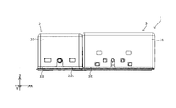
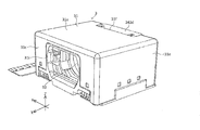
- FIG. 1A is a front view of the camera module according to Embodiment 1 of the present invention.
- FIG. 1B is a rear view of the camera module according to the first embodiment.
- FIG. 1C is a plan view of the camera module according to the first embodiment.
- FIG. 1D is a bottom view of the camera module according to the first embodiment.
- FIG. 1E is a right side view of the camera module according to Embodiment 1 of the present invention.
- FIG. 1F is a left side view of the camera module according to Embodiment 1 of the present invention.
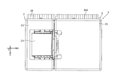
- FIG. 2 is a perspective view of the camera module according to the embodiment of the present invention.
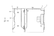
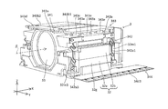
- FIG. 3 is a perspective view showing the prism module of the camera module with some members omitted.
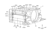
- FIG. 4 is a perspective view showing a prism module in which some members are omitted when viewed from a different angle from FIG.
- FIG. 5 is a perspective view of a state where the holder is assembled to the first base.
- FIG. 6 is a perspective view of the first base.
- FIG. 7 is a plan view of the first base.
- FIG. 8 is a perspective view showing only the swing support spring.
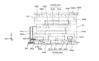
- FIG. 9 is a sectional view of the prism module.
- FIG. 10 is a perspective view of the holder.
- FIG. 11 is a bottom view of the holder.
- FIG. 12 is an enlarged side view of a portion P in FIG.
- FIG. 13A is a perspective view of the lens module.
- FIG. 13B is a perspective view of the lens module viewed from a different angle from FIG.
- FIG. 13C is a perspective view of the lens module in which some members are omitted.
- FIG. 14 is a perspective view showing a lens module in which some members are omitted when viewed from a different angle from FIG. 13C.
- FIG. 15 is a side view of the lens module from which the second base is omitted.
- FIG. 16 is a side view showing the lens module from which the second base is omitted when viewed from the opposite side to FIG.
- Figure 17 is a lens module that omit some members are A 1 arrow view of FIG. 15.
- FIG. 18 is a perspective view showing the spring taken out in an assembled state.
- FIG. 19 is a perspective view of the FPC, the AF actuator, and the rear OIS actuator.
- FIG. 19 is a perspective view of the FPC, the AF actuator, and the rear OIS actuator.
- FIG. 20 is a perspective view of the FPC, the AF actuator, and the rear OIS actuator viewed from a different angle from FIG.
- FIG. 21 is a circuit diagram of the AF drive control circuit.
- FIG. 22 is a perspective view of the second base.
- FIG. 23 is a perspective view of the second base viewed from a different angle from FIG.
- FIG. 24 is an exploded perspective view of the second base.
- FIG. 25 is a perspective view of the second base, the AF actuator, and the rear OIS actuator.
- FIG. 26 is a perspective view of the second base, the AF actuator, and the rear OIS actuator, as viewed from a different angle from FIG.
- FIG. 27 is a plan view of the lens module in which some members are omitted.
- FIG. 28 is a schematic plan view of the lens guide and the reference member.
- FIG. 29 is a plan view showing the lens module according to the second embodiment in a state where a part is omitted.
- FIG. 30 is a circuit diagram of the OIS drive control circuit.
- FIG. 31 is a perspective view showing Modification Example 1 of the lens module.
- FIG. 32A is a front view illustrating an example of a camera-mounted device equipped with a camera module.
- FIG. 32B is a rear view illustrating an example of a camera-mounted device equipped with a camera module.
- FIG. 33A is a front view of an automobile on which the on-vehicle camera module is mounted.
- FIG. 33B is a perspective view of an automobile equipped with the vehicle-mounted camera module.
- FIGS. 1A to 28. 1A to 1F are six views showing the appearance (design) of the camera module 1.
- FIG. 1A to 1F are six views showing the appearance (design) of the camera module 1.
- the camera actuator, camera module, and camera mounting device may include all configurations described below or may not include some configurations.
- the camera module 1 includes, for example, a mobile-side camera mounting device such as a smartphone M (see FIGS. 32A and 32B), a mobile phone, a digital camera, a notebook computer, a tablet terminal, and a mobile game machine, and a vehicle-mounted camera. Mounted on camera-mounted devices such as automobiles.
- each part constituting the camera module 1 of the present embodiment will be described based on the state of being incorporated in the camera module 1.
- the rectangular coordinate system (X, Y, Z) shown in each drawing is used.
- the camera module 1 is mounted such that, for example, when an image is actually taken by a camera mounting device, the X direction is the horizontal direction, the Y direction is the vertical direction, and the Z direction is the front and rear direction.
- Light from the subject enters the prism 23 of the prism module 2 from the + side (plus side) in the Z direction, as indicated by a dashed line ⁇ (also referred to as a first optical axis) in FIG.
- the light that has entered the prism 23 bends at an optical path bending surface 231 (see FIG. 9) of the prism 23, as shown by a chain line ⁇ (also referred to as a second optical axis) in FIGS.
- the light is guided to the lens unit 33 (see FIG. 13C) of the lens module 3 disposed downstream of (ie, on the + side in the X direction).
- the subject image formed by the lens unit 33 is captured by the image sensor module 4 (see FIG. 2) disposed downstream of the lens module 3.
- the camera module 1 described above is shake-corrected by a first shake correction device 24 (see FIG. 3) incorporated in the prism module 2 and a second shake correction device 35 (see FIG. 15) incorporated in the lens module 3.
- a first shake correction device 24 see FIG. 3
- a second shake correction device 35 see FIG. 15
- the camera module 1 performs autofocus by displacing the lens unit 33 in the X direction by the AF device 34 (see FIG. 15) incorporated in the lens module 3.
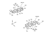
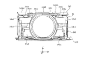
- the prism module 2 will be described with reference to FIGS. 1A to 12.
- the prism module 2 includes a first cover 21, a first base 22, a prism 23, and a first shake correction device 24.
- the first cover 21 is made of, for example, a synthetic resin or a non-magnetic metal, and has a box shape opened on both sides in the Z direction and on the + side in the X direction. Light from the subject side can pass through the opening of the first cover 21 in the + Z direction and enter the internal space of the first cover 21.
- the first cover 21 as described above is combined with a first base 22 described later from the + side in the Z direction.
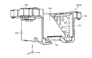
- the first base 22 will be described with reference to FIGS.
- the first base 22 has a box shape with an opening on the + side in the Z direction and the + side on the X direction.
- the first base 22 has a base-side opening 22b in the bottom wall 22a on the negative side in the Z direction.
- the first coil 27c and the first Hall element 27e of the front OIS actuator 27 are arranged in the base-side opening 22b.
- the first base 22 holds the holder 25 of the first shake correction device 24 via swing support springs 26A and 26B, which will be described later, on a first shaft 29L (also referred to as a swing center axis, which is parallel to the Y direction; see FIG. 6). ) Is supported.
- the first base 22 has a pair of first side walls 220 and 221 that are separated from each other in the Y direction and face each other.
- the first base 22 has a connection wall 222 that connects ends of the pair of first side walls 220 and 221 on the ⁇ side in the X direction.
- the first side walls 220 and 221 each have a first positioning projection 22c and a second positioning projection 22d at both ends in the X direction on the upper surface.
- the first positioning protrusion 22c and the second positioning protrusion 22d respectively engage with a pair of swing support springs 26A, 26B (see FIG. 8) described later to position the pair of swing support springs 26A, 26B. ing.
- the first shake correction device 24 will be described with reference to FIGS.
- the first shake correction device 24 is a first actuator, and swings the prism 23 about a first axis 29L (see FIG. 6) parallel to the Y direction to rotate the prism 23 about the first axis 29L. Is performed.
- Such a first shake correction device 24 is disposed in a first accommodation space 223 (see FIG. 9) covered by the first base 22 and the first cover 21.
- the first shake correction device 24 includes a holder 25, a pair of swing support springs 26A and 26B, a front OIS actuator 27, and the like.
- the holder 25 is supported by the first base 22 via a pair of swing support springs 26A and 26B so as to be displaceable (specifically, swingable). In this state, the holder 25 swings about the first shaft 29L based on the driving force of the front OIS actuator 27 (specifically, the thrust in the X direction).
- the front OIS actuator 27 is driven under the control of the control unit 5 (see FIG. 21)
- the holder 25 and the prism 23 swing about the first shaft 29L. Thereby, the shake in the rotation direction about the first shaft 29L is corrected.
- a specific structure of each member included in the first shake correction device 24 will be described.
- the holder 25 will be described with reference to FIG. 5 and FIGS.
- the holder 25 is made of, for example, a synthetic resin and holds the prism 23.
- the holder 25 and the prism 23 are swingably supported by the first base 22 via a pair of swing support springs 26A and 26B described later.
- the holder 25 includes a mounting surface 25a, a pair of opposing walls 25b and 25c, a pair of overhangs 25d and 25e, and a connection wall 25k.
- the mounting surface 25a faces the optical path bending surface 231 of the prism 23 from the back side (negative side in the Z direction).
- the mounting surface 25a has, for example, a surface parallel to the optical path bending surface 231.
- the mounting surface 25a is not limited to the structure of the present embodiment, and may be, for example, a boss capable of positioning the prism 23.
- the pair of opposing wall portions 25b and 25c are plate members parallel to the XZ plane, and are arranged separated from each other in the Y direction. Such a pair of opposing wall portions 25b and 25c are arranged so as to sandwich the mounting surface 25a from the Y direction.
- a pair of overhang portions 25d and 25e are provided on a pair of opposing wall portions 25b and 25c, respectively. Such a pair of overhang portions 25d and 25e respectively support the holder 25 so as to be swingable with respect to the first base 22.
- one (that is, the + side in the Y direction) protrusion 25d is provided on the + side in the Y direction of the opposing wall 25b, and projects from the side in the + side in the Y direction.
- One (ie, the Y-direction) overhang portion 25e is provided on the Y-direction-side surface of the opposing wall 25c, and projects from the side surface in the Y-direction side. Further, the pair of overhang portions 25d and 25e respectively have flat spring seat surfaces 25f and 25g (see FIG. 11) on the back surface (that is, the surface on the minus side in the Z direction). Each of the spring seat surfaces 25f and 25g has a pair of holder-side positioning projections 25h and 25i (see FIG. 11) protruding in the negative direction in the Z direction at two locations separated in the X direction.
- the surfaces of the first fixing portions 262 of the pair of swing support springs 26A and 26B on the + Z direction side are adhesively fixed to the spring seat surfaces 25f and 25g, respectively.
- the pair of holder-side positioning projections 25h and 25i are inserted into the pair of second through holes 26c of the swing support springs 26A and 26B, respectively.
- the holder 25 is swingably supported with respect to the first base 22.
- connection wall 25k connects the ends of the pair of opposing walls 25b and 25c on the negative side in the X direction in the Y direction.
- the holder 25 has a magnet holding portion 25j (see FIG. 9) for holding a first magnet 27a described later on the back surface.
- ⁇ Swinging support spring> With reference to FIG. 8, a pair of swing support springs 26A and 26B (also referred to as elastic support members) will be described. Each of the pair of swing support springs 26A and 26B elastically supports a holder 25 to be described later with respect to the first base 22. The pair of swing support springs 26A and 26B respectively support the holder 25 so as to be swingable about the first shaft 29L (see FIG. 6) with respect to the first base 22.
- the pair of swing support springs 26A and 26B are metal leaf springs, respectively, and have an upper surface of the first side wall portions 220 and 221 of the first base 22 and a lower surface of the pair of overhang portions 25d and 25e of the holder 25. It is located between.
- the swing support spring 26A of one of the pair of swing support springs 26A and 26B (that is, the Y direction + side) will be described.
- the other swing support spring 26B (that is, the minus side in the Y direction) is symmetric in the Y direction with one swing support spring 26A. For this reason, among the configurations of the swing support spring 26B, the same reference numerals are given to the same configurations as the swing support spring 26A.
- the swing support spring 26A has a first fixing portion 262, a pair of second fixing portions 260 and 261, a pair of connecting portions 263 and 264, and the like.
- One of the pair of second fixing portions 260 and 261 (that is, the + side in the X direction) is disposed at the end of the swing support spring 26A on the + side in the X direction.
- One such second fixing portion 260 has a first through hole 26a.
- the second fixing portion 261 on the other side (that is, on the negative side in the X direction) is arranged at the end on the negative side in the X direction of the swing support spring 26A.
- the other second fixing portion 261 has a first through hole 26b.
- the pair of second fixing portions 260 and 261 are connected to the first fixing portion 262 by a pair of connecting portions 263 and 264 extending in the X direction, respectively.
- the surfaces of the pair of second fixing portions 260 and 261 on the negative side in the Z direction are adhesively fixed to the end surfaces of the first side wall 220 of the first base 22 on the positive side in the Z direction.
- the first positioning protrusions 22c of the first side wall 220 are inserted into the first through holes 26a and 26b, respectively (see FIGS. 6 and 8).
- the surfaces of the pair of second fixing portions 260 and 261 on the negative side in the Z direction are bonded and fixed to the end surfaces of the first side wall 221 of the first base 22 on the positive side in the Z direction. I have.
- the second positioning projection 22d of the first side wall 221 is inserted into each of the first through holes 26a and 26b (see FIGS. 6 and 8).
- the first fixing portion 262 is provided at a portion between the second fixing portions 260 and 261 in the X direction via a gap in the X direction.
- the first fixing portion 262 has a pair of second through holes 26c.
- the surface of the first fixing portion 262 on the + side in the Z direction is adhesively fixed to a spring seat surface 25f formed on the back surface of the extension 25d of the holder 25.
- the surface of the first fixing portion 262 of the swing support spring 26B on the + side in the Z direction is adhesively fixed to a spring seat surface 25g formed on the back surface of the projecting portion 25e of the holder 25.
- a pair of holder-side positioning projections 25h formed on the back surface of the projecting portion 25d of the holder 25 are inserted into the pair of second through holes 26c, respectively.
- a pair of holder-side positioning projections 25i formed on the back surface of the projecting portion 25e of the holder 25 are inserted into the pair of second through holes 26c, respectively.
- the connecting part 263 of the pair of connecting parts 263 and 264 connects the second fixing part 260 and the first fixing part 262.
- the connecting portion 264 of the pair of connecting portions 263 and 264 connects the second fixing portion 261 and the first fixing portion 262.
- Each of the pair of connecting portions 263 and 264 has a substantially S-shaped linear shape.
- the pair of connecting portions 263, 264 are respectively straight portions 26d, 26e parallel to the Y direction (that is, parallel to the first shaft 29L) at ends (also referred to as one ends) on the side closer to the first fixing portion 262. Having.
- the straight portion 26d of the connection portion 263 and the straight portion 26e of the connection portion 264 constitute a torsion allowable portion 265.
- the torsion allowable portion 265 allows the first fixing portion 262 to twist with respect to the second fixing portions 260 and 261 by being twisted. That is, the holder 25 swings with respect to the first base 22 by twisting of the torsion allowance portion 265.
- the first shaft 29L which is the center of the swing of the holder 25, is constituted by the torsion allowable portion 265 of the swing support springs 26A, 26B. Therefore, the holder 25 does not need to include the swing center axis as a configuration. Thus, in the case of the present embodiment, the holder 25 is simply configured.
- the torsion allowable portion 265 allows relative displacement in the Z direction between the second fixing portions 260 and 261 and the first fixing portion 262 by being elastically deformed. That is, the torsion allowable portion 265 allows relative displacement in the Z direction between the first base 22 and the holder 25 by elastically deforming. With such a configuration, the impact transmitted from the first base 22 to the holder 25 is reduced.
- the torsion allowable portion 265 may be provided with a gel-like vibration damping member.
- the vibration damping member may be provided so as to cover the twist allowable portion 265. Further, the vibration damping member may be in contact with the upper surfaces of the first side walls 220 and 221 of the first base 22. Further, the vibration damping member may be in contact with the upper surfaces of the first side walls 220 and 221 of the first base 22 and the lower surfaces of the pair of overhangs 25 d and 25 e of the holder 25.
- the vibration damping member is effective in suppressing resonance of the pair of swing support springs 26A and 26B. From the viewpoint of suppressing the resonance, it is preferable that the vibration damping member is provided in the torsion permissible portion 265 that deforms most when used in the pair of swing support springs 26A and 26B. However, the vibration damping member may be provided at a portion other than the torsion allowable portion 265 of the pair of swing support springs 26A and 26B.
- the holder 25 and the first base 22 are not in direct contact. That is, in the assembled state, the holder 25 and the first base 22 are connected only via the pair of swing support springs 26A and 26B. In other words, the holder 25 and the first base 22 are apart from each other except for the connection between the pair of swing support springs 26A and 26B.
- the damping member is in contact with the first base 22 and the holder 25, the first base 22 and the holder 25 are connected only to the pair of swing support springs 26A and 26B and the damping member. Connected through.
- the peripheral surface of the first base 22 does not contact the peripheral surface of the holder 25 facing the peripheral surface in a predetermined direction.
- the holder 25 is supported (floating supported) so as to float on the first base 22 by the pair of swinging support springs 26A and 26B.
- the entire surface is located between the upper surface of the bottom wall portion 22 a of the first base 22 and the back surface of the holder 25 facing the low wall portion 22 a in the Z direction. There is a predetermined gap in the Z direction.
- the inner side surface (the Y-side surface) of the first side wall 220 of the first base 22 and the outer side surface (the Y-direction side surface) of the opposing wall portion 25b of the holder 25 facing the inner side surface There is a predetermined gap in the Y direction over the entire surface.
- the inner side surface of the first side wall portion 221 of the first base 22 (the + side surface in the Y direction) and the outer side surface of the opposing wall portion 25 c of the holder 25 facing the inner side surface (the ⁇ side surface in the Y direction)
- connection wall portion 222 of the first base 22 (the + side surface in the X direction) and the outer surface of the connection wall portion 25 k of the holder 25 facing the inner surface (the ⁇ side surface in the X direction).
- the upper surfaces of the first side walls 220 and 221 of the first base 22 (the surface on the + side in the Z direction) and the lower surfaces of the pair of protrusions 25d and 25e of the holder 25 facing the upper surface in the Z direction ( ⁇ Z direction). (A side surface), there is a gap in the Z direction over the entire surface.
- the pair of swing support springs 26A and 26B alleviate the impact applied to the holder 25 and the prism 23 from the first base 22. This suppresses damage to the holder 25 when the camera mounting device falls.
- the front OIS actuator 27 (also referred to as a first actuator) will be described with reference to FIGS.
- the front OIS actuator 27 swings the holder 25 about the first shaft 29L (see FIG. 6).
- the first axis 29L is an axis parallel to the Y direction.
- the first shaft 29L is a straight line connecting the center positions in the X direction of the first fixing portions 262 of the pair of swing support springs 26A and 26B.
- the front OIS actuator 27 is disposed on the back side (that is, the negative side in the Z direction) of the prism 23 and the holder 25 so as to overlap the optical path bending surface 231 of the prism 23 and the holder 25 in the Z direction (that is, the direction of the first optical axis). Have been.
- the front OIS actuator 27 includes a first magnet 27a, a first coil 27c, a first Hall element 27e, and the like.
- the first magnet 27a is fixed to the rear side surface (that is, the surface on the negative side in the Z direction) of the holder 25, which is a movable member. Specifically, the first magnet 27a is fixed to a magnet holding portion 25j provided on the back surface of the holder 25.
- the first magnet 27a is composed of two magnet elements adjacent in the X direction. Each of these magnet elements is magnetized in the Z direction, and has one magnetic pole on one side. The directions of the magnetic poles of each magnet element are opposite to each other.
- the first magnet 27a may include two magnet elements integrally formed.
- the first coil 27c and the first Hall element 27e are fixed to the surface of the flexible printed circuit board (hereinafter, referred to as FPC) 28 fixed to the back surface of the first base 22 (that is, the surface on the + side in the Z direction). I have.
- FPC flexible printed circuit board
- the first coil 27c and the first Hall element 27e are arranged in the base-side opening 22b of the first base 22.
- the first coil 27c is a so-called air-core coil having an oval shape. Note that the first coil 27c may be a so-called pattern coil printed on the surface of the FPC 28.
- the first Hall element 27e is arranged inside the first coil 27c in the radial direction.
- the front OIS actuator 27 having the above configuration swings the holder 25 about the first shaft 29L (see FIG. 6) under the control of the control unit 5 (see FIG. 21).
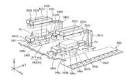
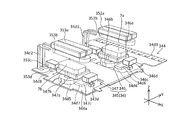
- lens module 3 will be described with reference to FIG. 2 and FIGS. 13A to 28.
- the lens module 3 includes a second cover 31, a second base 32, a lens unit 33, an AF device 34, and a second shake correction device 35.
- the lens module 3 shown in FIGS. 13A to 28 differs from, for example, the lens module 3 shown in FIG. 2 in the direction in which the terminals (such as a first terminal portion 34d1 described later) of the FPC project from the second base 32.
- the structure of the other parts in the lens module 3 shown in FIGS. 13A to 28 is substantially the same as that of the lens module 3 shown in FIG.
- the second cover 31 will be described with reference to FIGS. 2, 13A and 13B.
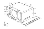
- the second cover 31 is made of, for example, a synthetic resin or a non-magnetic metal, and has a box shape that is open on both sides in the X direction and on the ⁇ side (that is, the back side) in the Z direction.
- the second cover 31 has a top plate portion 31a, a front plate portion 31b, a rear plate portion 31c, a first side plate portion 31d, and a second side plate portion 31e.
- the top plate portion 31a is a rectangular plate member. Such a top plate portion 31a is disposed on the + side in the Z direction of the second cover 31.
- the top plate portion 31a has a notch 31f at one end in the X direction (an end on the prism module 2 (see FIG. 2) side and an end on the negative side in the X direction).
- the notch 31f is cut out from the minus end in the X direction of the top plate portion 31a toward the plus side in the X direction.
- Such a notch 31f has a rectangular shape long in the Y direction in plan view.
- a connection member 343d described later is arranged in such a notch 31f.
- the front plate portion 31b is a rectangular plate member, and extends from the X-direction end of the top plate portion 31a to the Z-direction side.
- the front plate portion 31b has a front opening portion 31g in a portion including the central portion.
- the front opening 31g has a size such that the end surface on the ⁇ X direction side of the lens unit 33 can be exposed on the ⁇ X direction side.
- Light from the prism module 2 passes through the front opening 31g and enters the lens unit 33.
- the front opening 31g is continuous with the notch 31f of the top plate 31a. Therefore, the edge of the front opening 31g on the + side in the Z direction does not exist in the corner 31h formed by the top plate 31a and the front plate 31b. Such a configuration can facilitate the processing of the front opening 31g.
- the rear plate portion 31c is a rectangular plate member, and extends from the end of the top plate portion 31a on the plus side in the X direction to the minus side in the Z direction.
- the rear plate portion 31c has a rear opening 31i in a portion including the central portion.
- the rear opening 31i has a size such that the end surface of the lens unit 33 on the + side in the X direction can be exposed on the + side in the X direction.
- the light from the lens unit 33 passes through the rear opening 31i and enters the image sensor module 4.
- the first side plate portion 31d is a rectangular plate member, and extends from the end of the top plate portion 31a on the plus side in the Y direction to the minus side in the Z direction.
- the second side plate portion 31e is a rectangular plate member, and extends from the Y-direction end of the top plate portion 31a to the Z-direction side.
- the second cover 31 as described above is combined with a second base 32 described later from the + side in the Z direction.
- the second base 32 will be described with reference to FIGS. 13C, 14, and 22 to 26.
- the second base 32 is combined with the above-described second cover 31 to form a second accommodation space 32c (see FIG. 2) in which the lens unit 33, the AF device 34, and the second shake correction device 35 can be arranged. .
- the second base 32 is configured by combining a lower base element 32a and an upper base element 32b.
- the second base 32 has a bottom surface portion 32d and a pair of second side wall portions 32g, 32h.
- the bottom surface 32d has a base made of a synthetic resin, and a metal reinforcing plate 32k insert-molded on the base. Such a reinforcing plate 32k contributes to increasing the rigidity and reducing the thickness of the bottom surface portion 32d.
- the reinforcing plate 32k of the second base 32 is disposed on the minus side in the Z direction from a lens guide 341 described later so as to overlap the lens guide 341.
- the range in which the lens guide 341 can move during the autofocus operation that is, the range in which the lens guide 341 can move in the X direction
- the range in which the lens guide 341 can move during the shake correction operation that is, the range that can move in the Y direction
- the lens guide 341 exists on the + side in the Z direction of the reinforcing plate 32k. Therefore, the surface of the reinforcing plate 32k (that is, the surface on the + side in the Z direction) is always covered with the lens guide 341 and is not exposed. Thus, the light reflected by the reinforcing plate 32k is prevented from entering the lens unit 33 and eventually the image sensor of the image sensor module 4 described later.
- the second base 32 has bottom through holes 32e and 32f (see FIGS. 22 and 23) on both sides in the Y direction of the reinforcing plate 32k on the bottom surface 32d. As shown in FIGS. 25 and 26, a first AF coil 346b and a second AF coil 347b of an AF actuator 345 described later are arranged in the bottom through holes 32e and 32f, respectively.
- the second side walls 32g and 32h extend from both ends in the Y direction of the bottom surface 32d to the + side in the Z direction.
- the second side wall 32g is formed by combining the second lower wall element 32a1 of the lower base element 32a and the second upper wall element 32b1 of the upper base element 32b. It is configured.
- the second side wall portion 32h is configured by combining a second lower wall element 32a2 of the lower base element 32a and a second upper wall element 32b2 of the upper base element 32b.
- the second side wall portions 32g and 32h have coil mounting portions 32i and 32j, respectively.
- a first OIS coil 352b and a second OIS coil 353b of a second shake correction device 35 described later are mounted on such coil mounting portions 32i and 32j, respectively.
- the coil mounting portions 32i, 32j are provided on the upper surfaces of the second upper wall elements 32b1, 32b2 of the upper base element 32b.
- the coil mounting portion 32i is disposed between the first overhang portion 34a1 and the second overhang portion 34a3 of the lens guide 341 in the Z direction.
- the coil mounting portion 32j is disposed between the first overhang portion 34a2 and the second overhang portion 34a4 of the lens guide 341 in the Z direction.
- a first AF magnet 346a of an AF actuator 345 described below is disposed between the coil mounting portion 32i and the bottom surface 32d. Further, as shown in FIG. 26, a second AF magnet 347a of the AF actuator 345 is disposed between the coil mounting portion 32j and the bottom surface portion 32d. The first AF magnet 346a and the second AF magnet 347a are held by a lens guide 341 described later.
- the bottom surface through holes 32e and 32f and the coil mounting portions 32i and 32j overlap with a predetermined interval in the Z direction. Therefore, the first AF coil 346b and the second AF coil 347b disposed in the bottom through holes 32e and 32f, and the first OIS coil 352b and the second OIS coil 353b mounted on the coil mounting portions 32i and 32j. Overlap at a predetermined interval in the Z direction.
- the second side wall portion 32g has spring arranging portions 32m1 and 32m3 (see FIG. 13C) for arranging springs 342a1 and 342a3 to be described later at both ends in the X direction on the side surface on the + Y side.
- the second side wall portion 32h has spring disposing portions 32m2 and 32m4 (see FIG. 14) for disposing springs 342a2 and 342a4 described later on both ends in the X direction on the negative side surface in the Y direction.
- the second base 32 has a reference portion 32n at the end in the X direction + side.
- the reference portion 32n is a plate member provided at an end of the second base 32 on the + side in the X direction.
- Such a side surface of the reference portion 32n on the + side in the X direction is a reference surface in the X direction of the image sensor module 4 described later.
- the reference portion 32n has a first reference surface 32n1 (see FIG. 23), which is a reference surface in the X direction of a lens guide 341 to be described later, on the negative side surface in the X direction.
- Such a first reference plane 32n1 is also a reference for the later-described calibration.
- the reference portion 32n has a through hole at the center thereof for guiding the light passing through the lens portion 33 to the image sensor module 4.
- Such a reference portion 32n is a member for positioning the image sensor module 4.
- the lens portion 33 is disposed in the second housing space 32c (see FIG. 2) while being held by a lens guide 341 described later.
- a lens unit 33 has a cylindrical lens barrel and one or more lenses held by the lens barrel.
- the lens unit 33 has a telephoto lens group, for example, three times or more optically fixed between an end on the negative side in the X direction of the lens barrel and an end on the positive side in the X direction of the lens barrel. Note that the structure of the lens unit 33 is not limited to the above-described structure.
- the AF device 34 will be described with reference to FIGS. 13C to 21.
- the AF device 34 is a driving unit, and displaces the lens unit 33 in the X direction for the purpose of autofocus.
- the AF device 34 includes a lens guide 341, a first support mechanism 342, a second support mechanism 343, an FPC 344, and an AF actuator 345.
- FIG. 15 is a view of the lens module 3 in a state where some members are omitted, as viewed from the + side in the Y direction.
- FIG. 16 is a view of the lens module 3 in a state where some members are omitted, as viewed from the ⁇ side in the Y direction.
- FIG. 17 is a view of the lens module 3 in a state where the second base 32 is omitted, as viewed from the negative side in the X direction.
- the lens guide 341 has a cylindrical lens holding portion 341a, a pair of first overhang portions 34a1, 34a2, and a pair of second overhang portions 34a3, 34a4. Such a lens guide 341 is arranged in the second accommodation space 32c in a state where displacement in the X direction (that is, the direction of the second optical axis) and the Y direction is possible.
- the lens holding portion 341a has a housing space that can hold the lens barrel.
- a pair of first overhang portions 34a1 and 34a2 are provided so as to extend from two locations on the outer peripheral surface of the cylindrical lens holding portion 341a in directions opposite to each other in the Y direction.
- the pair of second overhang portions 34a3, 34a4 are respectively provided in the Y direction from two locations on the + Z direction side of the pair of first overhang portions 34a1, 34a2 on the outer peripheral surface of the cylindrical lens holding portion 341a. They are provided so as to extend in opposite directions.
- One (Y direction + side) of the first overhang 34a1 and one (Y direction + side) of the second overhang 34a3 overlap in the Z direction via a space 34b1.
- the other (Y-direction side) first overhang portion 34a2 and the other (Y-direction side) second overhang portion 34a4 overlap with each other via the space 34b2 in the Z direction.
- the lens guide 341 includes a first magnet holding portion 34a5 (see FIG. 15) for holding a first AF magnet 346a of an AF actuator 345 described later, and a first magnet holding portion 34a6 (FIG. 16) for holding a second AF magnet 347a. Reference). Specifically, the first magnet holding portions 34a5 and 34a6 are provided on the pair of first overhang portions 34a1 and 34a2, respectively.
- the first magnet holding portions 34a5 and 34a6 are concave portions opened on the negative side in the Z direction. Such first magnet holding portions 34a5 and 34a6 are respectively arranged on the negative side in the Z direction of the pair of coil mounting portions 32i and 32j of the second base 32 (see FIGS. 25 and 26).
- the pair of first magnet holding portions 34a5, 34a6 and the bottom through holes 32e, 32f of the second base 32 are provided on the same straight line parallel to the Z direction.
- the pair of first magnet holding portions 34a5 and 34a6 are provided on the + side in the Z direction with respect to the bottom surface through holes 32e and 32f.
- the lens guide 341 has a second magnet holding portion 34a7 (see FIG. 15) for holding a first OIS magnet 352a of a rear OIS actuator 351 described later.
- the lens guide 341 has a second magnet holding portion 34a8 (see FIG. 16) for holding the second OIS magnet 353a of the rear OIS actuator 351.
- the second magnet holding portions 34a7 and 34a8 are provided on the pair of second overhang portions 34a3 and 34a4, respectively.
- the pair of second magnet holding portions 34a7 and 34a8 are concave portions opened on the negative side in the Z direction.
- the pair of second magnet holding portions 34a7, 34a8 and the coil mounting portions 32i, 32j of the second base 32 are provided on the same straight line parallel to the Z direction.
- the pair of second magnet holding portions 34a7, 34a8 are provided on the + side in the Z direction with respect to the coil mounting portions 32i, 32j.
- the lens guide 341 has a third magnet holder 34b3 (see FIG. 15) near the first magnet holder 34a5 for holding the first X position detection magnet 346d of the AF actuator 345.
- the lens guide 341 has a third magnet holder 34b4 (see FIG. 16) that holds the second X position detection magnet 347d of the AF actuator 345 near the first magnet holder 34a6.
- the third magnet holding portions 34b3, 34b4 are respectively provided on the ⁇ X direction side of the first magnet holding portions 34a5, 34a6 of the pair of first overhang portions 34a1, 34a2. Note that the positions of the third magnet holding units 34b3 and 34b4 are not limited to the above positions as long as they are near the first magnet holding units 34a5 and 34a6.
- the lens guide 341 includes a pair of fourth magnet holding portions 34b5 and 34b6 (see FIGS. 15 and 16) that hold the Y position detection magnets 352c and 353c of the rear OIS actuator 351 near the first magnet holding portions 34a5 and 34a6. ).
- the pair of fourth magnet holding portions 34b5 and 34b6 are respectively provided on the X direction + side of the first magnet holding portions 34a5 and 34a6 among the pair of first overhang portions 34a1 and 34a2. .
- the positions of the pair of fourth magnet holding portions 34b5 and 34b6 are not limited to the above-described positions as long as they are near the first magnet holding portions 34a5 and 34a6.
- the lens guide 341 has a plurality of (six in the present embodiment) ball holding portions 343a (see FIG. 14) for holding a plurality of balls 343e of a second support mechanism 343 described later. Specifically, three of these ball holding portions 343a are provided on the surface of the pair of second overhang portions 34a3, 34a4 on the + side in the Z direction.
- the end surface of the lens guide 341 in the + X direction (hereinafter, referred to as “lens guide-side reference surface”) is the first reference surface 32n1 of the reference portion 32n. Abut.
- the lens guide-side reference surface of the lens guide 341 and the first reference surface 32n1 are flat surfaces parallel to the YZ plane. Therefore, in a state in which the lens guide-side reference surface of the lens guide 341 and the first reference surface 32n1 are in contact with each other (surface contact), the lens guide 341 moves Y in the X direction (that is, the direction of the second optical axis).
- the lens guide 341 is not inclined in the direction and the Z direction (hereinafter, referred to as “the reference state of the lens guide 341”).
- the first support mechanism 342 will be described with reference to FIGS. 13C to 16 and FIG.
- the first support mechanism 342 elastically supports the lens guide 341 on the second base 32 so as to be displaceable with respect to the second base 32.
- Such a first support mechanism 342 is also called an elastic support mechanism.
- the first support mechanism 342 has a plurality of (four in the present embodiment) springs 342a1 to 342a4, each of which is an elastic support member.
- the springs 342a1 to 342a4 elastically support the lens guide 341 on the second base 32.
- the lens unit 33 can be displaced in the X direction and the Y direction with respect to the second base 32.
- the displacement of the lens guide 341 in the Z direction with respect to the second base 32 is restricted to a predetermined range by the first support mechanism 342.
- the predetermined range is a range in which the lens guide 341 can be displaced based on the elastic deformation of the springs 342a1 to 342a4.
- the spring 342a1 supports the end of the lens guide 341 on the + side in the X direction and on the + side in the Y direction on the second base 32 (see FIG. 13C).
- the spring 342a2 supports the end of the lens guide 341 on the X direction + side and the Y direction-side on the second base 32 (see FIG. 14).
- the spring 342a3 supports an end of the lens guide 341 on the negative side in the X direction and on the positive side in the Y direction on the second base 32 (see FIG. 13C).
- the spring 342a4 supports the end of the lens guide 341 on the X direction-side and the Y direction-side on the second base 32 (see FIG. 14).
- each of the springs 342a1 to 342a4 has a first fixing portion 342b, a second fixing portion 342c, and a connection portion 342d.
- FIG. 18 shows the springs 342a1 to 342a4 as they are arranged in the assembled state.
- the first fixing portion 342b is fixed to a lens guide 341 which is a movable member.
- the second fixing portion 342c is fixed to the second base 32, which is a fixed member.
- the connecting portion 342d connects the first fixing portion 342b and the second fixing portion 342c.
- the connection portion 342d is made of, for example, a linear member that is at least partially curved (specifically, bent in a meandering shape).
- each of the connection portions 342d includes a first bent portion 342e and a second bent portion 342f in order from the + side in the Z direction.
- Such springs 342a1 to 342a4 are arranged on the spring arrangement portions 32m1 to 32m4 (see FIGS. 13C and 14) of the second base 32, respectively.
- the first bent portion 342e is a portion bent in a meandering shape, and is provided at one end (the end in the + Z direction) of the connecting portion 342d.
- the first bent portion 342e is elastically deformed in the length direction (Z direction) of the connection portion 342d.
- the position of the first bent portion 342e is not limited to the position of the present embodiment.
- the first bent portion 342e is preferably provided in a half portion on one side of the connection portion 342d (that is, a half portion on the first fixed portion 342b side). Further, it is more preferable that the first bent portion 342e is provided at one end of the connection portion 342d as in the present embodiment.
- each of the first bent portions 342e may be covered with a gel-like vibration damping member.
- the second bent portion 342f is a linear member that is provided at the other end (the end on the negative side in the Z direction) of the connecting portion 342d and is bent in a meandering shape.
- the second bent part 342f is elastically deformed in the length direction (Z direction) of the connection part 342d.
- the displacement of the second bent portion 342f when the lens portion 33 is displaced in the Z direction with respect to the second base 32 is smaller than the displacement of the first bent portion 342e.
- connection portion 342d When the lens portion 33 is displaced in the X direction with respect to the second base 32, the connection portion 342d is displaced so as to swing around the end near the second fixed portion 342c. Accordingly, the farther from the fulcrum (in other words, the closer to the first fixing portion 342b) the connecting portion 342d, the larger the displacement amount when the lens portion 33 is displaced in the X direction with respect to the second base 32.
- the position of the second bent portion 342f is not limited to the position of the present embodiment.
- the second bent portion 342f is preferably provided in a half portion on the other side of the connection portion 342d (that is, a half portion on the second fixed portion 342c side). Further, it is more preferable that the second bent portion 342f is provided at the other end of the connection portion 342d as in the present embodiment.
- the second bent portion 342f may be omitted. That is, the connecting portion 342d may have a configuration having a bent portion only at one place.
- each of the second bent portions 342f may be covered with a gel-like vibration damping member.
- connection portion 342d has directionality in the X direction.
- the spring 342a1 and the spring 342a2 are arranged so as to be in the same direction in the X direction.
- the spring 342a1 and the spring 342a2 are arranged such that at least the connection portions 342d overlap when viewed from the + side in the Y direction, for example.
- the spring 342a3 and the spring 342a4 are arranged so as to be in the same direction in the X direction. In other words, the spring 342a3 and the spring 342a4 are arranged such that at least the connection portion 342d overlaps when viewed from the + side in the Y direction, for example.
- the spring 342a1 and the spring 342a3 are arranged such that the connection portion 342d faces in the same direction in the X direction.
- the spring 342a2 and the spring 342a4 are arranged so that the connecting portion 342d faces in the same direction in the X direction.
- the center of gravity G of the movable side member at the reference position matches or substantially matches with the center of gravity G.
- the movable member refers to the lens guide 341 and each member fixed to the lens guide 341 and displaceable together with the lens guide 341.
- the movable side members include the lens guide 341, the lens unit 33, the first AF magnet 346a and the second AF magnet 347a of the AF actuator 345, and the first OIS of the rear OIS actuator 351. It is configured to include a magnet 352a, a second OIS magnet 353a, and the like.
- the center of each of the springs 342a1 to 342a4 is, for example, the center position in the Z direction and the center position in the X direction of each spring 342a1 to 342a4.
- the reference position of the lens guide 341 refers to a state where the lens guide 341 is not displaced in the X direction by the autofocus function and a state where the lens guide 341 is not displaced in the Y direction by the second shake correction device 35 described later.
- the springs 342a1 to 342a4 as described above are arranged as follows.
- a straight line passing through the center of gravity G and parallel to the direction of the second optical axis that is, the X direction
- L 4 straight line
- the pair of springs 342a1 and 342a2 on the + side in the X direction are and symmetrically with respect to L 4, they are arranged in two distant positions spaced by a predetermined distance in the X-direction positive side from the center of gravity G (right side in FIG. 18).
- X-direction - a pair of springs side 342a3,342a4 is symmetrical with respect to the straight line L 4, and, from the center of gravity G X direction - is disposed on the side above a predetermined distance apart two positions (the left side in FIG. 18) You.
- the intersection between the straight line L 1 and the straight line L 2 coincides with the center of gravity G.
- the second support mechanism 343 will be described with reference to FIGS. 13A to 17.
- the second support mechanism 343 supports the lens guide 341 on the second base 32 such that the lens guide 341 can be displaced in the XY plane with respect to the second base 32.
- the second support mechanism 343 supports the lens guide 341 in a state where displacement in the Z direction with respect to the second base 32 is restricted.
- the second support mechanism 343 supports the lens guide 341 in a state in which the lens guide 341 cannot be displaced in the + Z direction with respect to the second base 32.
- the second support mechanism 343 has a plurality of ball holding portions 343a, a pair of track members 343b1, 343b2, a connection member 343d, and a plurality of balls 343e.
- the plurality of ball holding portions 343a are provided on the surfaces of the second overhang portions 34a3 and 34a4 of the lens guide 341 on the + side in the Z direction.
- three ball holding portions 343a are provided on each of the surfaces on the + Z direction side of the second overhang portions 34a3 and 34a4.
- the pair of track members 343b1 and 343b2 are plate members parallel to the XY plane, for example.
- Each of the pair of track members 343b1 and 343b2 is made of a magnetic metal such as an iron-based alloy.
- the track member 343b1 and the first OIS magnet 352a arranged on the + side in the Y direction are arranged on the same straight line parallel to the Z direction. Further, the track member 343b1 is disposed on the + side in the Z direction with respect to the first OIS magnet 352a.
- the track member 343b2 and the second OIS magnet 353a arranged on the negative side in the Y direction are arranged on the same straight line parallel to the Z direction.
- the track member 343b2 is disposed on the + side in the Z direction with respect to the second OIS magnet 353a.
- the first OIS magnet 352a is attracted in the direction approaching the track member 343b1 (that is, in the Z direction + side) based on its own magnetic force.
- the second OIS magnet 353a is attracted in the direction approaching the track member 343b2 (that is, in the + Z direction) based on its magnetic force.
- Such a force acting between the first OIS magnet 352a and the second OIS magnet 353a and the track members 343b1 and 343b2 is, for example, when the springs 342a1 to 342a4 are omitted (that is, in the embodiment described later). 2), it is possible to float the movable member described above from the fixed member (second base 32).
- the pair of track members 343b1 and 343b2 are on the + Z direction side of the second overhang portions 34a3 and 34a4 of the lens guide 341 and the + Z direction surface of the second overhang portions 34a3 and 34a4, respectively. It is provided in the state facing.
- Each of the pair of track members 343b1 and 343b2 has a flat track surface 343c (see FIGS. 15 and 16) on the negative surface in the Z direction.
- the raceway surface 343c is opposed to the surface on the + Z direction side of the second overhang portions 34a3, 34a4 in the Z direction.
- connection member 343d The ends on the negative side in the X direction of the pair of track members 343b1 and 343b2 are connected by a connection member 343d.
- the connection member 343d is arranged in the notch 31f of the top plate 31a in the second cover 31 (see FIGS. 13A and 13C). In this state, the connection member 343d covers the entire cutout 31f. Accordingly, the connection member 343d prevents light from entering the lens unit 33 from the cutout 31f.
- the connection member 343d is fixed to the second cover 31. Since the second cover 31 is fixed to the second base 32, the connection member 343 d and the pair of track members 343 b 1 and 343 b 2 are fixed to the second base 32 via the second cover 31.
- the plurality of balls 343e are respectively held by the plurality of ball holding units 343a. In this state, the plurality of balls 343e are rotatably disposed between the inner surfaces of the plurality of ball holding portions 343a and the track surfaces 343c of the pair of track members 343b1 and 343b2. . The plurality of balls 343e are in contact with the inner surfaces of the plurality of ball holding portions 343a and the raceway surfaces 343c of the pair of raceway members 343b1, respectively.
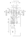
- the FPC 344 will be described with reference to FIGS. 19 to 21, FIG. 25, and FIG.
- the FPC 344 is a flexible printed circuit board, and is fixed to the second base 32 (see FIGS. 13C and 14).
- the FPC 344 includes an FPC base portion 344a, a first terminal portion 34d1, a second terminal portion 34d2, a third terminal portion 34d3, a first coil fixing portion 34d4, a second coil fixing portion 34d5, a first controller fixing portion 34d6, and a second controller. It has a fixing section 34d7, a hall element fixing section 34d8, and an AF drive control circuit 344b (see FIG. 21).
- the FPC base 344a is a plate member parallel to the XY plane, and is fixed to the second base 32 (see FIGS. 13C and 14).
- the first terminal portion 34d1 and the second terminal portion 34d2 respectively extend in the Z direction + side from two places separated in the Y direction at the X direction + side end of the FPC base 344a.
- the first terminal 34d1 is electrically connected to the first OIS coil 352b.
- the second terminal 34d2 is electrically connected to the second OIS coil 353b.
- the third terminal portion 34d3 is connected to the sensor substrate 6 (FIG. 21) on which the image sensor module 4 is mounted. As shown in FIG. 21, the third terminal unit 34d3 has a power terminal T1, a ground terminal T2, a data signal terminal T3, a first clock terminal T4, and a second clock terminal T5. In a state where the FPC 344 is connected to the sensor board 6, each terminal of the third terminal portion 34d3 is connected to each corresponding terminal in the board-side circuit 6a of the sensor board 6.
- the first coil fixing portion 34d4 and the second coil fixing portion 34d5 are respectively provided at positions facing the first magnet holding portions 34a5, 34a6 of the lens guide 341 in the Z direction on the + Z direction surface of the FPC base 344a. ing. Specifically, the first coil fixing portion 34d4 and the second coil fixing portion 34d5 are connected to one side (Y direction + side) of the FPC base 344a in the Y direction centering on the second optical axis on the surface in the Z direction + side. ) And the other side in the Y direction ( ⁇ side in the Y direction).
- a first AF coil 346b and a second AF coil 347b are fixed to the first coil fixing portion 34d4 and the second coil fixing portion 34d5, respectively.
- the first coil fixing portion 34d4 and the second coil fixing portion 34d5 are respectively disposed in bottom through holes 32e and 32f of the second base 32 (see FIGS. 22 and 23).
- the first controller fixing part 34d6 and the second controller fixing part 34d7 are provided near the first coil fixing part 34d4 and the second coil fixing part 34d5, respectively, on the surface of the FPC base 344a on the + side in the Z direction. Specifically, the first controller fixing portion 34d6 and the second controller fixing portion 34d7 are respectively more in the X direction than the first coil fixing portion 34d4 and the second coil fixing portion 34d5 on the + Z direction surface of the FPC base 344a. It is provided near the negative side.
- a first AF controller 346c and a second AF controller 347c are fixed to the first controller fixing unit 34d6 and the second controller fixing unit 34d7, respectively.
- the Hall element fixing portion 34d8 is provided at a position facing the fourth magnet holding portion 34b6 (see FIG. 16) of the lens guide 341 in the Z direction on the surface of the FPC base 344a on the + side in the Z direction.
- An OIS Hall element 353d of a rear OIS actuator 351 described later is fixed to the Hall element fixing portion 34d8.
- the AF drive control circuit 344b includes a first power line L1, a second power line L2, a first ground line L3, a second ground line L4, a first data signal line L5, and a second data signal. It has a line L6, a first clock line L7, a second clock line L8, first coil power supply lines L9, L10, and second coil power supply lines L11, L12.
- the first power supply line L1 is a transmission line for a current supplied from the control unit 5 mounted on the sensor board 6 to the first AF controller 346c.
- One end of the first power supply line L1 is connected to the power supply terminal T1 of the third terminal portion 34d3.
- the other end of the first power supply line L1 is connected to an input-side power supply terminal (not shown) of the first AF controller 346c.
- the second power supply line L2 is a transmission line for a current supplied from the control unit 5 mounted on the sensor board 6 to the second AF controller 347c.
- One end of the second power supply line L2 is connected to the power supply terminal T1 of the third terminal portion 34d3.
- the other end of the second power line L2 is connected to a power input terminal (not shown) of the second AF controller 347c.
- the first power supply line L1 and the second power supply line L2 are branched on the way.
- the first ground line L3 is a transmission line for ground. One end of the first ground line L3 is connected to the ground terminal T2 of the third terminal portion 34d3. The other end of the first ground line L3 is connected to a ground terminal (not shown) of the first AF controller 346c.
- the second ground line L4 is a transmission line for ground. One end of the second ground line L4 is connected to the ground terminal T2 of the third terminal portion 34d3. The other end of the second ground line L4 is connected to a ground terminal (not shown) of the second AF controller 347c.
- the first ground line L3 and the second ground line L4 are branched on the way.
- the first data signal line L5 is a transmission line for a control signal between the control unit 5 and the first AF controller 346c. One end of the first data signal line L5 is connected to the data signal terminal T3 of the third terminal portion 34d3. The other end of the first data signal line L5 is connected to an input data signal terminal (not shown) of the first AF controller 346c.
- the second data signal line L6 is a control signal transmission line between the control unit 5 and the second AF controller 347c. One end of the second data signal line L6 is connected to the data signal terminal T3 of the third terminal part 34d3. The other end of the second data signal line L6 is connected to an input-side data signal terminal (not shown) of the second AF controller 347c.
- the first data signal line L5 and the second data signal line L6 are branched on the way.
- the first clock line L7 is a transmission line of a clock signal between the control unit 5 and the first AF controller 346c. One end of the first clock line L7 is connected to the first clock terminal T4 of the third terminal 34d3. The other end of the first clock line L7 is connected to a clock terminal (not shown) of the first AF controller 346c.
- the second clock line L8 is a transmission line of a clock signal between the control unit 5 and the second AF controller 347c. One end of the second clock line L8 is connected to the second clock terminal T5 of the third terminal 34d3. The other end of the second clock line L8 is connected to a clock terminal (not shown) of the second AF controller 347c.
- the first coil power supply lines L9 and L10 are transmission lines that connect the first AF controller 346c and the first AF coil 346b.
- One end of the first coil power supply line L9 is connected to a first terminal (not shown) of the output side power supply terminal of the first AF controller 346c.
- the other end of the first coil power supply line L9 is connected to one end of the first AF coil 346b.
- One end of the first coil power supply line L10 is connected to a second terminal (not shown) of the output side power supply terminal of the first AF controller 346c.
- the other end of the first coil power supply line L10 is connected to the other end of the first AF coil 346b.
- the second coil power supply lines L11 and L12 are transmission lines that connect the second AF controller 347c and the second AF coil 347b.
- One end of the second coil power supply line L11 is connected to a first terminal (not shown) of the output side power supply terminal of the second AF controller 347c.
- the other end of the second coil power supply line L11 is connected to one end of the second AF coil 347b.
- One end of the second coil power supply line L12 is connected to a second terminal (not shown) of the output side power supply terminal of the second AF controller 347c.
- the other end of the second coil power supply line L12 is connected to the other end of the second AF coil 347b.
- the AF drive control circuit 344b as described above is connected to the sensor substrate 6 via the third terminal 34d3.
- the first AF controller 346c and the second AF controller 347c are connected to the control unit 5 mounted on the sensor board 6.
- the AF actuator 345 will be described with reference to FIG. 15, FIG. 16, and FIG.
- the AF actuator 345 (also referred to as a third actuator) is a driving mechanism that displaces the lens guide 341 in the X direction (direction of the second optical axis) during autofocus.
- the AF actuator 345 has a first AF actuator 346 disposed on the + side in the Y direction and a second AF actuator 347 disposed on the ⁇ side in the Y direction.
- the first AF actuator 346 is a driving mechanism, and includes a first AF magnet 346a, a first AF coil 346b, a first X position detection magnet 346d, and a first AF controller 346c.
- the second AF actuator 347 is a driving mechanism, and includes a second AF magnet 347a, a second AF coil 347b, a second X position detection magnet 347d, and a second AF controller 347c.
- first AF actuator 346 and a second AF actuator 347 the first AF magnet 346a and the second AF magnet 347a are fixed to the lens guide 341 which is a movable member, and the first AF coil 346b and the The second AF coil 347b is a moving magnet type actuator fixed to the second base 32 which is a fixed side member.
- the first AF actuator 346 and the second AF actuator 347 may be moving coil type actuators.
- the arrangement of each unit constituting the AF actuator 345 will be described.
- each of the first AF magnet 346a and the second AF magnet 347a is composed of two magnet elements (reference numerals are omitted) arranged so as to be adjacent to each other in the Y direction. Each of these magnet elements is magnetized in the Z direction and arranged so that the directions of the magnetic poles are opposite.
- Each of the first AF magnet 346a and the second AF magnet 347a is a rectangular parallelepiped that is long in the X direction and, for example, has a substantially rectangular shape when viewed from the Y direction (the state shown in FIGS. 15 and 16). .
- the first AF coil 346b and the second AF coil 347b are so-called elliptical so-called air-core coils that are supplied with power during auto focus.
- the first AF coil 346b and the second AF coil 347b are fixed to the first coil fixing portion 34d4 and the second coil fixing portion 34d5 of the FPC 344 via a substrate (not shown), respectively, in a state where the long axes are aligned with the Y direction. Have been.
- the first AF coil 346b is connected to the first AF controller 346c via the first coil power supply lines L9 and L10.
- the current value of the first AF coil 346b is controlled by the first AF controller 346c.
- the first X position detection magnet 346d and the second X position detection magnet 347d are magnetized in the Z direction, and are, for example, rectangular parallelepipeds having a substantially rectangular shape when viewed from the Y direction (the state shown in FIGS. 15 and 16). is there. Such a first X position detection magnet 346d and a second X position detection magnet 347d are respectively held by a pair of third magnet holding portions 34b3, 34b4 of the lens guide 341.
- the first AF controller 346c is fixed to the first controller fixing portion 34d6 of the FPC 344. As shown in FIG. 21, such a first AF controller 346c has a first detection unit 346e and a first drive control unit 346f.
- the first detector 346e detects a magnetic flux (also referred to as position information) between the first AF magnet 346a and the first X position detection magnet 346d.
- the first detection unit 346e sends the detection value to the first drive control unit 346f.
- the first drive control unit 346f obtains a position (also referred to as a first position) of the first AF magnet 346a in the X direction based on the detection value received from the first detection unit 346e. Then, the first drive control unit 346f controls the current value of the first AF coil 346b based on the detection value received from the first detection unit 346e. Note that the first AF controller 346c does not control the current value of the second AF coil 347b.
- the closed loop control is performed based on the detection value of the first detection unit 346e.
- the first drive control unit 346f may be omitted.
- the processing performed by the first drive control unit 346f may be performed by, for example, the control unit 5 mounted on the sensor board 6.
- the second AF controller 347c is fixed to the second controller fixing portion 34d7 of the FPC 344. As shown in FIG. 21, the second AF controller 347c includes a second detection unit 347e and a second drive control unit 347f.
- the second detector 347e detects a magnetic flux (also referred to as position information) between the second AF magnet 347a and the second X position detection magnet 347d.
- the second detector 347e sends the detected value to the second drive controller 347f.
- the second drive control unit 347f obtains a position (also referred to as a second position) of the second AF magnet 347a in the X direction based on the detection value (information regarding the position) received from the second detection unit 347e. Further, the second drive control unit 347f controls the current value of the second AF coil 347b based on the detection value received from the second detection unit 347e. Note that the second AF controller 347c does not control the current value of the first AF coil 346b.
- closed loop control is performed based on the detection value of the second AF controller 347c.
- the second drive control unit 347f may be omitted.
- the process performed by the second drive control unit 347f may be performed by, for example, the control unit 5 mounted on the sensor board 6.
- the current is supplied to the first AF coil 346b and the second AF coil 347b under the control of the first AF controller 346c and the second AF controller 347c. Flows, a Lorentz force (thrust) for displacing the first AF magnet 346a and the second AF magnet 347a in the X direction is generated.
- Such thrust is switched by controlling the direction of the current flowing through the first AF coil 346b and the second AF coil 347b. Thereby, the displacement direction of the lens guide 341 can be switched.
- the current value of the first AF coil 346b of the first AF actuator 346 and the current value of the second AF coil 347b of the second AF actuator 347 are controlled independently, so that the first AF The thrust generated by the actuator 346 and the thrust generated by the second AF actuator 347 can be made different.
- the thrust generated by the AF actuator 345 includes only the first thrust in the X direction.
- the thrust generated by the AF actuator 345 is equal to the first thrust in the X direction and the thrust of the movable member.
- a second thrust which is a moment about the center of gravity G.
- the second thrust is a resistance against an external force that tends to cause the lens guide 341 to deviate from the X direction during autofocus. This allows the AF actuator 345 to reduce or eliminate the amount of deviation of the lens guide 341 from the X direction during autofocus.
- the above-mentioned external force will be described later.
- the AF actuator 345 resists an external force acting so as to deviate the movable member (the lens guide 341) from the Y direction when the second shake correction device 35 described later performs shake correction. It is also a second drive mechanism that generates a resistance force.
- the AF actuator 345 controls the first AF magnet 346a and the second AF magnet 347a in the X direction by the first AF controller 346c and the second AF controller 347c. The position at is detected.
- the first AF controller 346c and the second AF controller 347c respectively control the current values of the first AF coil 346b and the second AF coil 347b based on the detected values. Accordingly, when the second shake correction device 35 performs shake correction, the AF actuator 345 generates a resistance to an external force that causes the lens guide 341 to deviate from the Y direction. As a result, the AF actuator 345 can reduce or eliminate the amount of deviation of the lens guide 341 from the Y direction during shake correction.
- the second shake correction device 35 will be described with reference to FIG. 15, FIG. 16, and FIG.
- the second shake correction device 35 is a drive unit, and performs shake correction in the Y direction by displacing the lens unit 33 in the Y direction.
- Such a second shake correction device 35 is disposed in the above-described second accommodation space 32c (see FIG. 2).
- the second shake correction device 35 includes the above-described lens guide 341, the above-described plurality of springs 342a1 to 342a4, the above-described FPC 344, and the rear OIS actuator 351.
- the lens guide 341, the springs 342a1 to 342a4, and the FPC 344 are common to the AF device 34.
- the rear OIS actuator 351 (also referred to as a second actuator) is a driving mechanism, and includes a first OIS actuator 352 disposed on the + side in the Y direction and a second OIS actuator 353 disposed on the ⁇ side in the Y direction. Having.
- the first OIS actuator 352 is a driving mechanism, and is arranged so as to overlap the first AF actuator 346 at a predetermined interval in the Z direction.
- a first OIS actuator 352 has a first OIS magnet 352a, a first OIS coil 352b, and a Y position detection magnet 352c.
- the second OIS actuator 353 is a driving mechanism and is arranged so as to overlap the second AF actuator 347 at a predetermined interval in the Z direction.
- a second OIS actuator 353 has a second OIS magnet 353a, a second OIS coil 353b, a Y position detection magnet 353c, and an OIS Hall element 353d.
- the center of the driving force of the rear OIS actuator 351 is adjusted to the AF actuator 345. To or near the center of the driving force.
- This configuration makes it difficult for the lens guide 341 to undergo tilt displacement (that is, swing displacement about an axis parallel to the Y direction or the Z direction) during autofocus and shake correction.
- the first OIS magnet 352a and the second OIS magnet 353a are fixed to the lens guide 341 which is a movable member, and the first OIS coil 352b and the second OIS coil 353b are fixed.
- the moving magnet type actuator is fixed to the second base 32 as a member.
- the rear OIS actuator 351 may be a moving coil type actuator.
- the first OIS magnet 352a and the second OIS magnet 353a are held by the second magnet holding portion 34a7 and the second magnet holding portion 34a8 of the lens guide 341 respectively.
- each of the first OIS magnet 352a and the second OIS magnet 353a is composed of two magnet elements (symbols omitted) arranged side by side in the Y direction. Each of these magnet elements is magnetized in the Z direction and arranged so that the directions of the magnetic poles are opposite.
- the first OIS coil 352b and the second OIS coil 353b are each an elliptic so-called air-core coil that is supplied with power at the time of shake correction.
- the first OIS coil 352b and the second OIS coil 353b are fixed to the coil mounting portions 32i and 32j of the second base 32, respectively, with their major axes aligned in the X direction. In this state, the first OIS coil 352b and the second OIS coil 353b overlap with the first OIS magnet 352a and the second OIS magnet 353a, respectively, at a predetermined interval in the Z direction.
- At least a part of the first OIS actuator 352 (the first OIS magnet 352a and the first OIS coil 352b) has the first overhang portion 34a1 and the second overhang portion 34a3 of the lens guide 341 in the Z direction. It is located between.
- at least a part of the second OIS actuator 353 (the second OIS magnet 353a and the second OIS coil 353b) is located between the first overhang portion 34a2 and the second overhang portion 34a4 of the lens guide 341 in the Z direction. are located in Such a configuration is effective for reducing the height of the lens module 3 and thus the camera module 1.
- the Y position detection magnet 352c is held by the fourth magnet holding portion 34b5 of the lens guide 341.
- the Y position detection magnet 353c is held by the fourth magnet holding portion 34b6 of the lens guide 341.
- the OIS Hall element 353d is fixed to the Hall element fixing portion 34d8 (see FIG. 19) of the FPC 344.
- the OIS Hall element 353d detects a magnetic flux (also referred to as position information) of the Y position detection magnet 353c, and sends a detection value to the control unit 5 (see FIG. 21) mounted on the sensor board 6.
- the control unit 5 obtains the position of the Y position detection magnet 353c (that is, the lens guide 341) in the Y direction based on the detection value received from the OIS Hall element 353d.
- the rear OIS actuator 351 having the above configuration, when a current flows through the first OIS coil 352b and the second OIS coil 353b via the FPC 344 under the control of the control unit 5, the first OIS magnet 352a and A Lorentz force for displacing the second OIS magnet 353a in the Y direction is generated. Since the first OIS magnet 352a and the second OIS magnet 353a are each fixed to the lens guide 341, the lens guide 341 is displaced in the Y direction based on the Lorentz force. The direction of displacement of the lens guide 341 is switched by controlling the direction of the current flowing through the first OIS coil 352b and the second OIS coil 353b.
- shield plates 7a and 7b made of magnetic metal are arranged.
- the image sensor module 4 is arranged on the + side in the X direction with respect to the lens unit 33.
- the image sensor module 4 includes an image sensor such as a charge-coupled device (CCD) image sensor and a complementary metal oxide semiconductor (CMOS) image sensor.
- CMOS complementary metal oxide semiconductor
- the image sensor of the image sensor module 4 captures a subject image formed by the lens unit 33 and outputs an electric signal corresponding to the subject image.
- a sensor substrate 6 is electrically connected to the image sensor module 4, and power is supplied to the image sensor module 4 via the sensor substrate 6 and an electric signal of a subject image picked up by the image sensor module 4 is output.
- Such an image sensor module 4 may have a conventionally known structure.
- the second shake correcting device 35 When the second shake correcting device 35 performs shake correction, power is supplied to the first OIS coil 352b and the second OIS coil 353b. Specifically, in the second shake correction device 35, the first OIS is detected based on a detection signal from a shake detection unit (not shown, for example, a gyro sensor) so that the shake in the Y direction of the camera module 1 is canceled.
- the current values of the coil 352b and the second OIS coil 353b are controlled. Such control is performed by the control unit 5, for example. At this time, the displacement of the lens guide 341 can be accurately controlled by feeding back the detection value of the OIS Hall element 353d to the control unit 5.
- the direction of the Lorentz force is one of the directions in the Y direction or the other direction (also referred to as a specific direction). Since the first OIS coil 352b and the second OIS coil 353b are fixed to the second base 32, a reaction force acts on the first OIS magnet 352a and the second OIS magnet 353a. This reaction force becomes the driving force of the voice coil motor for OIS, and the lens guide 341 holding the first OIS magnet 352a and the second OIS magnet 353a is displaced in the Y direction on the XY plane, and shake correction is performed.
- the above-described shake correction is preferably performed by displacing the lens guide 341 in parallel with the Y direction, for example, as indicated by an arrow AY1 in FIG.
- an external force for example, a moment in the direction of arrow Af in FIG. 27
- the lens guide 341 will turn to the arrow in FIG.
- a Displacement occurs in a direction deviating from the Y direction as in A Y2 .
- the external force described above for example, the center position of the distributed arrangement in the spring 342a1 ⁇ 342a4 constituting the first supporting mechanism 342 described above (the point of intersection of the straight line L 1 and the straight line L 2 in FIG. 18), the movable side of the above
- the deviation may occur due to a deviation from the center of gravity G of the member.
- the above-described external force is generated due to individual differences of the springs 342a1 to 342a4 constituting the first support mechanism 342, for example.
- Such an external force may be, for example, a force directed in the X direction, in addition to the moment described above.
- the external force may include a moment and a force directed in the X direction.
- the AF actuator 345 is driven under the control of the control unit 5 to generate a resistance (second thrust) against the external force. Specifically, at the time of shake correction, the AF actuator 345 detects the position of the first AF magnet 346a by the first AF controller 346c (that is, the first detection unit 346e), and also detects the position of the second AF controller 347c (that is, The position of the second AF magnet 347a is detected by the second detector 347e).
- the first AF controller 346c (that is, the first drive control unit 346f) receives the control signal (for example, the displacement direction and the displacement amount for shake correction) received from the control unit 5 and the first detection unit 346e.
- a current value of the first AF coil 346b (hereinafter, referred to as a first current value) is controlled based on the detected value.
- the second AF controller 347c (that is, the second drive control unit 347f) performs a current value of the second AF coil 347b (hereinafter, referred to as a second current value) based on the detection value of the second detection unit 347e. Control.
- the AF actuator 345 generates the above-described resistance (for example, moment) based on the thrust of the first AF actuator 346 and the thrust of the second AF actuator 347.
- the first current value and the second current value are selected from the preliminary data stored in the first drive control unit 346f and the second drive control unit 347f by, for example, calibration performed in advance.
- the preliminary data includes, for example, the displacement direction (for example, the direction of arrow A Y1 in FIG. 27) and the displacement amount D 1 (see FIG. 27) when the lens guide 341 is displaced in the Y direction by the second shake correction device 35. ), A deviation direction of the lens guide 341 from the Y direction (for example, the direction of the arrow AY in FIG. 27), and a deviation correction parameter D 2 from the Y direction of the lens guide 341 (see FIG. 27).
- Resistance force AF actuator 345 generates for the above-described external force, for example, a rotational moment in the direction of arrow A r in FIG. Then, the AF actuator 345 causes the generated resistance to act on the lens guide 341. As a result, the lens guide 341 exerted by the resultant force of the thrust parallel to the Y direction (also referred to as a specific direction) generated by the second shake correction device 35 and the resistance generated by the AF actuator 345 acts on the lens guide 341. In the operating state, it can be displaced parallel to the Y direction as indicated by an arrow A Y1 in FIG.
- the AF device 34 When the AF device 34 performs autofocus, power is supplied to the first AF coil 346b and the second AF coil 347b.
- the current value in the first AF coil 346b is controlled by the first AF controller 346c.
- the current value in the second AF coil 347b is controlled by the second AF controller 347c.
- the first AF controller 346c determines a second AF signal based on a control signal received from the control unit 5 via the first data signal line L5 and a detection value of the first detection unit 346e of the first AF controller 346c.
- the current value (first current value) of one AF coil 346b is controlled.
- the second AF controller 347c is configured to control the second AF coil based on the control signal received from the control unit 5 via the second data signal line L6 and the detection value of the second detection unit 347e of the second AF controller 347c.
- the current value of 347b (second current value) is controlled.
- the direction of the resultant force of each Lorentz force is one of the other in the X direction. It is. Since the first AF magnet 346a and the second AF magnet 347a are fixed to the second base 32, a reaction force acts on the first AF coil 346b and the second AF coil 347b. This reaction force becomes the driving force of the voice coil motor for AF, and the lens guide 341 holding the first AF coil 346b and the second AF coil 347b moves in the X direction (the direction of the second optical axis), and the auto focus is performed. Is
- an external force for example, a moment in the direction of arrow Af in FIG. 27
- an external force that causes the displacement of the lens guide 341 to deviate from the X direction
- an external force acts, if the thrust acting on the lens guide 341 is only the thrust parallel to the X direction (first thrust), the lens guide 341 is moved from the X direction as indicated by an arrow AX2 in FIG. It is displaced in a deviated direction.
- Such an external force may be, for example, a force directed in the Y direction, in addition to the moment described above.
- the external force may include a moment and a force directed in the Y direction.
- the AF actuator 345 detects the position of the first AF magnet 346a by the first AF controller 346c (that is, the first detection unit 346e), and also detects the position of the second AF controller 347c (that is, The position of the second AF magnet 347a is detected by the second detector 347e).
- the AF actuator 345 controls the current value of the first AF coil 346b by the first AF controller 346c (that is, the first drive control unit 346f), and also controls the second AF controller 347c (that is, the second drive control unit 347f). ) Controls the current value of the second AF coil 347b.
- the thrust generated by the first AF actuator 346 and the thrust generated by the second AF actuator 347 are made different. Based on such a difference in thrust, the AF actuator 345 generates a thrust including a thrust parallel to the X direction (first thrust) and the above-described resistance (second thrust).
- the thrust parallel to the X direction is a combined force of the thrust generated by the first AF actuator 346 and the thrust generated by the second AF actuator 347.
- the resistance force of the above (secondary thrust) is the a thrust first AF actuator 346 occurs, occurs on the basis of the difference between the thrusts second AF actuator 347 occurs moment (see arrow A r in FIG. 27) .
- the first current value and the second current value are selected from preliminary data stored in the first drive control unit 346f and the second drive control unit 347f by, for example, calibration performed in advance.
- the preliminary data for example, in the case of displacing the lens guide 341 in the X direction by the AF actuator 345, the displacement direction (e.g., the direction of the arrow Ax 1 in FIG. 27), the displacement amount D 3 (see FIG. 27), the lens departure direction of the X direction guides 341 (e.g., arrow a X direction in FIG. 27) and the AF parameter consisting deviation amount D 4 (see FIG.
- the first current value and the second current value corresponding to the AF parameters are obtained in the range of the entire stroke of the lens guide 341 in the X direction.
- Resistance force AF actuator 345 generates for the above-described external force, for example, a rotational moment in the direction of arrow A r in FIG. Then, the AF actuator 345 causes the generated thrust (the resultant force of the first thrust and the second thrust) to act on the lens guide 341. As a result, the lens guide 341 to which such a thrust has acted can be displaced in parallel with the X direction as indicated by an arrow Ax1 in FIG. 27 in a state where the external force acts.
- the lens guide 341 is inclined with respect to the Y direction and the Z direction (specifically, the first reference surface 32n1 of the reference portion 32n) in the stopped state. May be applied. Such a force is generated due to an assembly error or an individual difference between the springs 342a1 to 342a4 constituting the first support mechanism 342. If such a tilt exists, the lens guide 341 will be displaced while maintaining this tilt during autofocusing.
- the impact transmitted from the first base 22 that is the fixed member to the holder 25 that is the movable member is a pair of swing support springs. Alleviated by 26A and 26B.
- the pair of swing support springs 26A and 26B (specifically, the straight portions 26d and 26e) constitute the first shaft 29L that is the swing center of the holder 25.
- the holder 25 is supported so as to float on the first base 22 (floating support), there is no hard contact point between the holder 25 and the first base 22. Therefore, when an impact is applied to the camera module 1, no indentation or the like based on the impact is generated on the holder 25 or the first base 22.
- Embodiment 2 according to the present invention will be described with reference to FIG. 29 and FIG.
- the camera module of the present embodiment is different from the above-described first embodiment in the structure of the rear OIS actuator 351B of the second shake correction device.
- the camera module of the present embodiment will be described focusing on a structure different from that of the first embodiment.
- the rear OIS actuator 351B is a drive mechanism, and includes a first OIS actuator 352B arranged on the + side in the Y direction and a second OIS actuator 353B arranged on the-side in the Y direction.
- the first OIS actuator 352B has a first OIS magnet 352a and a pair of first OIS coils 352b1 and 352b2.
- the first OIS magnet 352a is the same as in the first embodiment.
- the pair of first OIS coils 352b1 and 352b2 are so-called air-core coils each having an elliptical shape to be supplied with power during shake correction.
- Each of the pair of first OIS coils 352b1 and 352b2 is fixed to the coil mounting portion 32i of the second base 32 in a state where the major axes coincide with each other in the X direction.
- the second OIS actuator 353B has a second OIS magnet 353a, a pair of second OIS coils 353b1, 353b2, a first OIS controller 353e, and a second OIS controller 353f.
- the second OIS magnet 353a is the same as in the first embodiment.
- the pair of second OIS coils 353b1 and 353b2 are so-called elliptic air-core coils that are supplied with power at the time of shake correction.
- Each of the pair of second OIS coils 353b1 and 353b2 is fixed to the coil mounting portion 32j of the second base 32 in a state where the major axes coincide with each other in the X direction.
- the second OIS coil 353b1 is electrically connected to the first OIS coil 352b1.
- the second OIS coil 353b2 is electrically connected to the first OIS coil 352b2.
- the first OIS coil 352b1 and the second OIS coil 353b1 are connected to the first OIS controller 353e via the first coil power supply lines L9a and L10a.
- the current values of the first OIS coil 352b1 and the second OIS coil 353b1 are controlled by the first OIS controller 353e.
- the first OIS coil 352b2 and the second OIS coil 353b2 are connected to the second OIS controller 353f via the second coil power supply lines L11a and L12a.
- the current values of the first OIS coil 352b2 and the second OIS coil 353b2 are controlled by the second OIS controller 353f.
- the first OIS controller 353e is fixed to the FPC 344B. Such a first OIS controller 353e has a first detection unit 353g and a first drive control unit 353h.
- the first detection unit 353g detects the magnetic flux (also referred to as position information) of the second OIS magnet 353a at the position where the first detection unit 353g is fixed.
- the first detection unit 353g sends the detection value to the first drive control unit 353h.
- the first drive control unit 353h controls the current values of the first OIS coil 352b1 and the second OIS coil 353b1, based on the detection value received from the first detection unit 353g. Note that the first drive control unit 353h does not control the current values of the first OIS coil 352b2 and the second OIS coil 353b2.
- the second OIS controller 353f is fixed to the FPC 344B. Such a second OIS controller 353f has a second detection unit 353i and a second drive control unit 353j.
- the second detector 353i detects the magnetic flux (also referred to as position information) of the second OIS magnet 353a at the position where the second detector 353i is fixed.
- the second detection unit 353i sends the detection value to the second drive control unit 353j.
- the second drive control unit 353j controls the current values of the first OIS coil 352b2 and the second OIS coil 353b2 based on the detection value received from the second detection unit 353i. Note that the second drive control unit 353j does not control the current values of the first OIS coil 352b1 and the second OIS coil 353b1.
- the rear OIS actuator 351B as described above is connected to the control unit 5 by an OIS drive control circuit 344c as shown in FIG.
- the OIS drive control circuit 344c is provided in the FPC 344B.
- the OIS drive control circuit 344c includes a first power line L1a, a second power line L2a, a first ground line L3a, a second ground line L4a, a first data signal line L5a, and a second data signal. It has a line L6a, a first clock line L7a, a second clock line L8a, first coil power supply lines L9a and L10a, and second coil power supply lines L11a and L12a.
- Such an OIS drive control circuit 344c is substantially the same as the AF drive control circuit 344b in the first embodiment. Therefore, a detailed description of the OIS drive control circuit 344c is omitted.
- the description of the AF drive control circuit 344b in the first embodiment can be appropriately replaced.
- the configuration of the present embodiment as described above is achieved by independently controlling the current values of the first OIS coil 352b1 and the second OIS coil 353b1 and the current values of the first OIS coil 352b2 and the second OIS coil 353b2.
- a second OIS coil 353b2, a first OIS magnet 352a, and an actuator (hereinafter, referred to as a second actuator) constituted by the second OIS magnet 353a can be made to have a different thrust.
- the thrust generated by the rear OIS actuator 351B includes only the first thrust in the Y direction.
- the thrust generated by the rear OIS actuator 351B is the thrust generated by the first actuator and the thrust generated by the second actuator. It has a first thrust in the Y direction, which is a resultant force, and a second thrust, which is a moment about the center of gravity G of the movable member generated based on this resultant force.
- the second thrust is a resistance against an external force that tends to cause the lens guide 341 to deviate from the Y direction during shake correction. This allows the rear OIS actuator 351B to reduce or eliminate the amount of deviation of the lens guide 341 from the X direction during shake correction.
- Other configurations, operations, and effects are the same as those in the first embodiment.
- the operation of the camera module according to the present embodiment at the time of shake correction may be appropriately replaced with the operation of the camera module according to the first embodiment.
- the configuration of the present embodiment can be implemented in combination with the configuration of the above-described first embodiment as appropriate within a technically consistent range.
- the camera module elastically supports the movable member with respect to the fixed member, and the movable member can be displaced in the XY plane with respect to the fixed member. And a second support mechanism that supports the Z-direction so as not to be displaced.
- the configuration of the support mechanism that supports the movable member displaceably with respect to the fixed member is not limited to the first support mechanism and the second support mechanism described above.
- the lens module 3B illustrated in FIG. 31 has a configuration in which the first support mechanism 342 (see FIGS. 13C, 14, and 18) is omitted from the lens module 3 of the above-described first and second embodiments. .
- the lens module 3B shown in FIG. 31 has a second support mechanism 343 (FIGS. 13C and 13C) in the first and second embodiments described above as a support mechanism for supporting the movable member displaceably with respect to the fixed member. 14 (see FIG. 14).
- the structure of the second support mechanism 343 is the same as that of the first embodiment.
- the configuration corresponding to the first support mechanism 342 for example, the spring arrangement portions 32m1 to 32m4 of the second base 32, etc. 13C and FIG. 14).
- the lens module has only the first support mechanism 342 in the first and second embodiments as a support mechanism for supporting the movable member displaceably with respect to the fixed member. May be.
- the first support mechanism that elastically supports the movable member with respect to the fixed member may be configured by a plurality of suspension wires (not shown) instead of the spring disposition portions 32m1 to 32m4.
- a smartphone that is a mobile terminal with a camera has been described as an example of a camera-equipped device including the camera module 1, but the present invention has been obtained with a camera module and a camera module.
- the present invention can be applied to a camera mounted device having an image processing unit for processing image information.
- the camera-mounted device includes an information device and a transport device.
- the information devices include, for example, a camera-equipped mobile phone, a notebook computer, a tablet terminal, a portable game machine, a web camera, and a camera-equipped in-vehicle device (eg, a back monitor device, a drive recorder device).
- the transportation device includes, for example, an automobile.
- FIGS. 33A and 33B are diagrams showing an automobile V as a camera-mounted device equipped with a vehicle-mounted camera module VC (Vehicle-Camera).
- FIG. 33A is a front view of the vehicle V
- FIG. 33B is a rear perspective view of the vehicle V.
- the vehicle V mounts the camera module 1 described in the embodiment as the vehicle-mounted camera module VC.
- the vehicle-mounted camera module VC is attached to, for example, a windshield toward the front or to a rear gate toward the rear.
- the vehicle-mounted camera module VC is used for a back monitor, a drive recorder, a collision avoidance control, an automatic driving control, and the like.
- the configurations of the voice col motor for AF and the voice coil motor for OIS in the present invention are not limited to those described in the above embodiments.
- an elastic support member made of an elastomer or the like is used instead of the springs 342a1 to 342a4 of the first support mechanism 342 shown in each of the above embodiments. It can also be applied.
- the present invention can be applied to a lens driving device having only an AF function without an OIS function. Further, the present invention can be applied to a lens driving device having only an OIS function without having an AF function.
- the camera actuator and camera module according to the present invention can be mounted on a thin camera-mounted device such as a smartphone, a mobile phone, a digital camera, a notebook computer, a tablet terminal, a portable game machine, and a vehicle-mounted camera.
- a thin camera-mounted device such as a smartphone, a mobile phone, a digital camera, a notebook computer, a tablet terminal, a portable game machine, and a vehicle-mounted camera.
Abstract
A camera actuator comprises: a fixed-side member; a light path bending member that bends light that is incident along a first direction in a second direction; a movable-side member that holds the light path bending member; a first actuator that causes the movable-side member to swing in relation to the fixed-side member about a swinging center axis that is orthogonal to the first direction and the second direction; and an elastic support member that elastically supports the movable-side member in relation to the fixed-side member, the elastic support member comprising a first fixed part that is fixed to the movable-side member in a position corresponding to the position of the swinging center axis, a pair of second fixed parts that sandwich the position of the swinging center axis and are fixed to the fixed-side member at mutually separated positions, and connection parts that extend from each of the pair of second fixed parts toward the position of the swinging center axis and connect to the first fixed part.
Description
本発明は、カメラ用アクチュエータ、カメラモジュール、およびカメラ搭載装置に関する。
The present invention relates to a camera actuator, a camera module, and a camera mounting device.
従来、スマートフォンやデジタルカメラなど、カメラモジュールを搭載した薄型のカメラ搭載装置が知られている。カメラモジュールは、1以上のレンズを有するレンズ部と、レンズ部により結像された被写体像を撮像する撮像素子とを備える。
Conventionally, thin camera-equipped devices, such as smartphones and digital cameras, equipped with a camera module have been known. The camera module includes a lens unit having one or more lenses, and an image sensor that captures a subject image formed by the lens unit.
また、レンズ部の前段に設けられた光路屈曲部材であるプリズムにより、第一光軸に沿う被写体からの光を第二光軸の方向に屈曲して後段のレンズ部に導光する屈曲光学系を備えるカメラモジュールも提案されている(例えば、特許文献1)。
In addition, a bending optical system that bends light from a subject along the first optical axis in the direction of the second optical axis and guides the light to the subsequent lens unit by a prism that is an optical path bending member provided at the front stage of the lens unit. There is also proposed a camera module including (for example, Patent Document 1).
特許文献1に開示されたカメラモジュールは、カメラに生じる手振れを補正する振れ補正装置、および、オートフォーカスを行うオートフォーカス装置を備えている。このようなカメラモジュールは、カメラ用アクチュエータとして振れ補正用アクチュエータおよびオートフォーカス用アクチュエータを有する。このうちの振れ補正用アクチュエータは、異なる二軸を中心にプリズムを揺動させる第一アクチュエータおよび第二アクチュエータを備えている。カメラに手振れが生じると、制御部の制御下で振れ補正用アクチュエータがプリズムを揺動させて振れ補正を行う。これによりカメラに生じた手振れが補正される。
The camera module disclosed in Patent Literature 1 includes a shake correction device that corrects camera shake that occurs in a camera, and an autofocus device that performs autofocus. Such a camera module has a shake correction actuator and an autofocus actuator as camera actuators. The shake correcting actuator includes a first actuator and a second actuator that swing the prism about two different axes. When a camera shake occurs in the camera, the shake correction actuator swings the prism under the control of the control unit to perform the shake correction. As a result, camera shake caused by the camera is corrected.
ところで、上述のような特許文献1に開示されたカメラ用アクチュエータの場合、プリズムを保持する可動側部材は、固定側部材に揺動可能な状態で直接的に支持されている。このため、たとえば、カメラ用アクチュエータが搭載されたカメラ搭載装置に衝撃が加わった場合に、当該衝撃が、固定側部材から可動側部材に伝わり、可動側部材が損傷し易くなる可能性がある。このような損傷が可動側部材に生じると、上述の振れ補正の精度が低下してしまう可能性がある。
By the way, in the case of the camera actuator disclosed in Patent Document 1 described above, the movable-side member holding the prism is directly supported by the fixed-side member in a swingable state. For this reason, for example, when an impact is applied to a camera mounting device on which a camera actuator is mounted, the impact may be transmitted from the fixed member to the movable member, and the movable member may be easily damaged. If such damage occurs in the movable member, the accuracy of the above-described shake correction may be reduced.
本発明の目的は、固定側部材から可動側部材に伝わる衝撃を緩和できるカメラ用アクチュエータ、カメラモジュール、およびカメラ搭載装置を提供することである。
An object of the present invention is to provide a camera actuator, a camera module, and a camera mounting device that can reduce an impact transmitted from a fixed member to a movable member.
本発明に係るカメラ用アクチュエータの一態様は、固定側部材と、第一方向に沿う入射光を第二方向に屈曲させる光路屈曲部材と、光路屈曲部材を保持する可動側部材と、固定側部材に対して可動側部材を、第一方向および第二方向に直交する揺動中心軸を中心として揺動させる第一アクチュエータと、固定側部材に対して可動側部材を弾性的に支持する弾性支持部材と、を備え、弾性支持部材は、揺動中心軸の位置に対応する位置で可動側部材に固定される第一固定部と、揺動中心軸の位置を挟んで互いに離間した位置で固定側部材に固定される一対の第二固定部と、一対の第二固定部からそれぞれ揺動中心軸の位置へ向けて延びて第一固定部に接続する接続部と、を備える。
One aspect of the camera actuator according to the present invention includes a fixed member, an optical path bending member that bends incident light along a first direction in a second direction, a movable member that holds the optical path bending member, and a fixed member. A first actuator for swinging the movable member about a swing center axis perpendicular to the first direction and the second direction, and an elastic support for elastically supporting the movable member relative to the fixed member. A first fixing portion fixed to the movable member at a position corresponding to the position of the swing center axis, and fixed at a position separated from each other with the position of the swing center axis therebetween. The vehicle includes a pair of second fixing portions fixed to the side member, and a connecting portion extending from the pair of second fixing portions toward the position of the swing center axis and connecting to the first fixing portion.
本発明に係るカメラモジュールの一態様は、上述のカメラ用アクチュエータと、レンズ部の後段に配置された撮像素子と、を備える。
の 一 One embodiment of the camera module according to the present invention includes the above-described camera actuator and an imaging element arranged at a stage subsequent to the lens unit.
本発明に係るカメラ搭載装置の一態様は、上述のカメラモジュールと、当該カメラモジュールを制御する制御部と、を有する。
の 一 One embodiment of a camera-mounted device according to the present invention includes the above-described camera module and a control unit that controls the camera module.
本発明によれば、固定側部材から可動側部材に伝わる衝撃を緩和できるカメラ用アクチュエータ、カメラモジュール、およびカメラ搭載装置を提供できる。
According to the present invention, it is possible to provide a camera actuator, a camera module, and a camera mounting device capable of reducing an impact transmitted from a fixed member to a movable member.
以下、本発明に係る実施形態を図面に基づいて詳細に説明する。
Hereinafter, embodiments of the present invention will be described in detail with reference to the drawings.
[実施形態1]
図1A~図28を参照して、本発明の実施形態1に係るカメラモジュールについて説明する。図1A~図1Fは、カメラモジュール1の外観(意匠)を示す六面図である。 [Embodiment 1]
A camera module according toEmbodiment 1 of the present invention will be described with reference to FIGS. 1A to 28. 1A to 1F are six views showing the appearance (design) of the camera module 1. FIG.
図1A~図28を参照して、本発明の実施形態1に係るカメラモジュールについて説明する。図1A~図1Fは、カメラモジュール1の外観(意匠)を示す六面図である。 [Embodiment 1]
A camera module according to
以下、カメラモジュール1の概要について説明した後、カメラモジュール1が備えるプリズムモジュール2、レンズモジュール3、および撮像素子モジュール4の具体的構造について説明する。なお、本発明に係るカメラ用アクチュエータ、カメラモジュール、およびカメラ搭載装置は、後述する全ての構成を備えてもよいし、一部の構成を備えなくてもよい。
Hereinafter, after describing the outline of the camera module 1, the specific structures of the prism module 2, the lens module 3, and the imaging element module 4 included in the camera module 1 will be described. Note that the camera actuator, camera module, and camera mounting device according to the present invention may include all configurations described below or may not include some configurations.
<カメラモジュール>
カメラモジュール1は、たとえばスマートフォンM(図32A、図32B参照)、携帯電話機、デジタルカメラ、ノート型パソコン、タブレット端末、および携帯型ゲーム機などの携帯側のカメラ搭載装置、ならびに、車載カメラを搭載した自動車などのカメラ搭載装置に搭載される。 <Camera module>
Thecamera module 1 includes, for example, a mobile-side camera mounting device such as a smartphone M (see FIGS. 32A and 32B), a mobile phone, a digital camera, a notebook computer, a tablet terminal, and a mobile game machine, and a vehicle-mounted camera. Mounted on camera-mounted devices such as automobiles.
カメラモジュール1は、たとえばスマートフォンM(図32A、図32B参照)、携帯電話機、デジタルカメラ、ノート型パソコン、タブレット端末、および携帯型ゲーム機などの携帯側のカメラ搭載装置、ならびに、車載カメラを搭載した自動車などのカメラ搭載装置に搭載される。 <Camera module>
The
以下、本実施形態のカメラモジュール1を構成する各部については、カメラモジュール1に組み込まれた状態を基準として説明する。また、本実施形態のカメラモジュール1の構造を説明するにあたり、各図に示された直交座標系(X,Y,Z)を使用する。
Hereinafter, each part constituting the camera module 1 of the present embodiment will be described based on the state of being incorporated in the camera module 1. In describing the structure of the camera module 1 of the present embodiment, the rectangular coordinate system (X, Y, Z) shown in each drawing is used.
カメラモジュール1は、カメラ搭載装置で実際に撮影が行われる場合に、たとえばX方向が左右方向、Y方向が上下方向、Z方向が前後方向となるように搭載される。被写体からの光は、図3に一点鎖線α(第一光軸ともいう。)で示されるように、Z方向+側(プラス側)からプリズムモジュール2のプリズム23に入射する。プリズム23に入射した光は、図3および図13Cに一点鎖線β(第二光軸ともいう。)で示されるように、プリズム23の光路屈曲面231(図9参照)で屈曲して、プリズム23よりも後段(つまり、X方向+側)に配置されたレンズモジュール3のレンズ部33(図13C参照)へと導光される。そして、レンズ部33により結像された被写体像が、レンズモジュール3の後段に配置された撮像素子モジュール4(図2参照)により撮像される。
The camera module 1 is mounted such that, for example, when an image is actually taken by a camera mounting device, the X direction is the horizontal direction, the Y direction is the vertical direction, and the Z direction is the front and rear direction. Light from the subject enters the prism 23 of the prism module 2 from the + side (plus side) in the Z direction, as indicated by a dashed line α (also referred to as a first optical axis) in FIG. The light that has entered the prism 23 bends at an optical path bending surface 231 (see FIG. 9) of the prism 23, as shown by a chain line β (also referred to as a second optical axis) in FIGS. The light is guided to the lens unit 33 (see FIG. 13C) of the lens module 3 disposed downstream of (ie, on the + side in the X direction). Then, the subject image formed by the lens unit 33 is captured by the image sensor module 4 (see FIG. 2) disposed downstream of the lens module 3.
上述のカメラモジュール1は、プリズムモジュール2に組み込まれた第一振れ補正装置24(図3参照)、および、レンズモジュール3に組み込まれた第二振れ補正装置35(図15参照)により、振れ補正(OIS:Optical Image Stabilization)を行う。また、上述のカメラモジュール1は、レンズモジュール3に組み込まれたAF装置34(図15参照)によりレンズ部33をX方向に変位させて、オートフォーカスを行う。
The camera module 1 described above is shake-corrected by a first shake correction device 24 (see FIG. 3) incorporated in the prism module 2 and a second shake correction device 35 (see FIG. 15) incorporated in the lens module 3. (OIS: Optical Image Stabilization). The camera module 1 performs autofocus by displacing the lens unit 33 in the X direction by the AF device 34 (see FIG. 15) incorporated in the lens module 3.
<プリズムモジュール>
図1A~図12を参照してプリズムモジュール2について説明する。プリズムモジュール2は、第一カバー21、第一ベース22、プリズム23、および第一振れ補正装置24を備える。 <Prism module>
Theprism module 2 will be described with reference to FIGS. 1A to 12. The prism module 2 includes a first cover 21, a first base 22, a prism 23, and a first shake correction device 24.
図1A~図12を参照してプリズムモジュール2について説明する。プリズムモジュール2は、第一カバー21、第一ベース22、プリズム23、および第一振れ補正装置24を備える。 <Prism module>
The
<第一カバー>
第一カバー21は、図1A~図2に示されるように、たとえば合成樹脂製または非磁性金属製であり、Z方向両側およびX方向+側が開口した箱状である。被写体側からの光は、第一カバー21のZ方向+側の開口部を通過して第一カバー21の内部空間に侵入可能である。以上のような第一カバー21は、後述する第一ベース22にZ方向+側から組み合わされている。 <First cover>
As shown in FIGS. 1A and 2, thefirst cover 21 is made of, for example, a synthetic resin or a non-magnetic metal, and has a box shape opened on both sides in the Z direction and on the + side in the X direction. Light from the subject side can pass through the opening of the first cover 21 in the + Z direction and enter the internal space of the first cover 21. The first cover 21 as described above is combined with a first base 22 described later from the + side in the Z direction.
第一カバー21は、図1A~図2に示されるように、たとえば合成樹脂製または非磁性金属製であり、Z方向両側およびX方向+側が開口した箱状である。被写体側からの光は、第一カバー21のZ方向+側の開口部を通過して第一カバー21の内部空間に侵入可能である。以上のような第一カバー21は、後述する第一ベース22にZ方向+側から組み合わされている。 <First cover>
As shown in FIGS. 1A and 2, the
<第一ベース>
図6および図7を参照して第一ベース22について説明する。第一ベース22は、Z方向+側およびX方向+側がそれぞれ開口した箱状である。第一ベース22は、Z方向-側の底壁部22aに、ベース側開口部22bを有する。 <First base>
Thefirst base 22 will be described with reference to FIGS. The first base 22 has a box shape with an opening on the + side in the Z direction and the + side on the X direction. The first base 22 has a base-side opening 22b in the bottom wall 22a on the negative side in the Z direction.
図6および図7を参照して第一ベース22について説明する。第一ベース22は、Z方向+側およびX方向+側がそれぞれ開口した箱状である。第一ベース22は、Z方向-側の底壁部22aに、ベース側開口部22bを有する。 <First base>
The
本実施形態の場合、ベース側開口部22bに、前側OISアクチュエータ27の第一コイル27cおよび第一ホール素子27eが配置されている。
In the case of the present embodiment, the first coil 27c and the first Hall element 27e of the front OIS actuator 27 are arranged in the base-side opening 22b.
第一ベース22は、後述の揺動支持バネ26A、26Bを介して、第一振れ補正装置24のホルダ25を、Y方向に平行な第一軸29L(揺動中心軸ともいう。図6参照)を中心とした揺動を可能に支持している。第一ベース22は、Y方向に離隔しかつ対向した一対の第一側壁部220、221を有する。また、第一ベース22は、一対の第一側壁部220、221のX方向-側の端部同士を接続する接続壁部222を有する。
The first base 22 holds the holder 25 of the first shake correction device 24 via swing support springs 26A and 26B, which will be described later, on a first shaft 29L (also referred to as a swing center axis, which is parallel to the Y direction; see FIG. 6). ) Is supported. The first base 22 has a pair of first side walls 220 and 221 that are separated from each other in the Y direction and face each other. In addition, the first base 22 has a connection wall 222 that connects ends of the pair of first side walls 220 and 221 on the − side in the X direction.
第一側壁部220、221はそれぞれ、上面におけるX方向両端部に、第一位置決め凸部22cおよび第二位置決め凸部22dを有する。第一位置決め凸部22cおよび第二位置決め凸部22dはそれぞれ、後述する一対の揺動支持バネ26A、26B(図8参照)と係合して、一対の揺動支持バネ26A、26Bを位置決めしている。
The first side walls 220 and 221 each have a first positioning projection 22c and a second positioning projection 22d at both ends in the X direction on the upper surface. The first positioning protrusion 22c and the second positioning protrusion 22d respectively engage with a pair of swing support springs 26A, 26B (see FIG. 8) described later to position the pair of swing support springs 26A, 26B. ing.
<第一振れ補正装置>
図5~図9を参照して第一振れ補正装置24について説明する。第一振れ補正装置24は、第一アクチュエータであって、Y方向に平行な第一軸29L(図6参照)を中心にプリズム23を揺動させて、第一軸29Lを中心とした回転方向の振れ補正を行う。このような第一振れ補正装置24は、第一ベース22と第一カバー21とで覆われる第一収容空間223(図9参照)に配置されている。 <First shake correction device>
The firstshake correction device 24 will be described with reference to FIGS. The first shake correction device 24 is a first actuator, and swings the prism 23 about a first axis 29L (see FIG. 6) parallel to the Y direction to rotate the prism 23 about the first axis 29L. Is performed. Such a first shake correction device 24 is disposed in a first accommodation space 223 (see FIG. 9) covered by the first base 22 and the first cover 21.
図5~図9を参照して第一振れ補正装置24について説明する。第一振れ補正装置24は、第一アクチュエータであって、Y方向に平行な第一軸29L(図6参照)を中心にプリズム23を揺動させて、第一軸29Lを中心とした回転方向の振れ補正を行う。このような第一振れ補正装置24は、第一ベース22と第一カバー21とで覆われる第一収容空間223(図9参照)に配置されている。 <First shake correction device>
The first
第一振れ補正装置24は、ホルダ25、一対の揺動支持バネ26A、26B、および前側OISアクチュエータ27などを備える。
The first shake correction device 24 includes a holder 25, a pair of swing support springs 26A and 26B, a front OIS actuator 27, and the like.
第一振れ補正装置24において、ホルダ25は、一対の揺動支持バネ26A、26Bを介して、第一ベース22に変位可能(具体的には、揺動可能)に支持されている。この状態でホルダ25は、前側OISアクチュエータ27の駆動力(具体的には、X方向の推力)に基づいて第一軸29Lを中心に揺動する。制御部5(図21参照)の制御下で前側OISアクチュエータ27が駆動すると、ホルダ25およびプリズム23が、第一軸29Lを中心に揺動する。これにより、第一軸29Lを中心とした回転方向の振れが補正される。以下、第一振れ補正装置24が備える各部材の具体的構造について説明する。
In the first shake correction device 24, the holder 25 is supported by the first base 22 via a pair of swing support springs 26A and 26B so as to be displaceable (specifically, swingable). In this state, the holder 25 swings about the first shaft 29L based on the driving force of the front OIS actuator 27 (specifically, the thrust in the X direction). When the front OIS actuator 27 is driven under the control of the control unit 5 (see FIG. 21), the holder 25 and the prism 23 swing about the first shaft 29L. Thereby, the shake in the rotation direction about the first shaft 29L is corrected. Hereinafter, a specific structure of each member included in the first shake correction device 24 will be described.
<ホルダ>
図5および図9~図11を参照して、ホルダ25について説明する。ホルダ25は、たとえば、合成樹脂製であって、プリズム23を保持している。ホルダ25とプリズム23とは、後述の一対の揺動支持バネ26A、26Bを介して、第一ベース22に揺動可能に支持されている。 <Holder>
Theholder 25 will be described with reference to FIG. 5 and FIGS. The holder 25 is made of, for example, a synthetic resin and holds the prism 23. The holder 25 and the prism 23 are swingably supported by the first base 22 via a pair of swing support springs 26A and 26B described later.
図5および図9~図11を参照して、ホルダ25について説明する。ホルダ25は、たとえば、合成樹脂製であって、プリズム23を保持している。ホルダ25とプリズム23とは、後述の一対の揺動支持バネ26A、26Bを介して、第一ベース22に揺動可能に支持されている。 <Holder>
The
ホルダ25は、載置面25a、一対の対向壁部25b、25c、一対の張出し部25d、25e、および接続壁部25kを備える。
The holder 25 includes a mounting surface 25a, a pair of opposing walls 25b and 25c, a pair of overhangs 25d and 25e, and a connection wall 25k.
載置面25aは、プリズム23の光路屈曲面231に裏側(Z方向-側)から対面する。載置面25aは、たとえば、光路屈曲面231と平行な面を有する。なお、載置面25aは、本実施形態の構造に限定されず、たとえば、プリズム23を位置決めすることが可能なボスなどでもよい。
(4) The mounting surface 25a faces the optical path bending surface 231 of the prism 23 from the back side (negative side in the Z direction). The mounting surface 25a has, for example, a surface parallel to the optical path bending surface 231. The mounting surface 25a is not limited to the structure of the present embodiment, and may be, for example, a boss capable of positioning the prism 23.
一対の対向壁部25b、25cはそれぞれ、XZ平面に平行な板部材であって、Y方向に離隔した状態で配置されている。このような一対の対向壁部25b、25cは、載置面25aをY方向から挟んで配置されている。
The pair of opposing wall portions 25b and 25c are plate members parallel to the XZ plane, and are arranged separated from each other in the Y direction. Such a pair of opposing wall portions 25b and 25c are arranged so as to sandwich the mounting surface 25a from the Y direction.
一対の張出し部25d、25eはそれぞれ、一対の対向壁部25b、25cに設けられている。このような一対の張出し部25d、25eはそれぞれ、ホルダ25を、第一ベース22に対して揺動可能に支持している。
A pair of overhang portions 25d and 25e are provided on a pair of opposing wall portions 25b and 25c, respectively. Such a pair of overhang portions 25d and 25e respectively support the holder 25 so as to be swingable with respect to the first base 22.
具体的には、一方(つまり、Y方向+側)の張出し部25dは、対向壁部25bのY方向+側面に設けられ、当該側面からY方向+側に張り出している。
Specifically, one (that is, the + side in the Y direction) protrusion 25d is provided on the + side in the Y direction of the opposing wall 25b, and projects from the side in the + side in the Y direction.
一方、他方(つまり、Y方向-側)の張出し部25eは、対向壁部25cのY方向-側面に設けられ、当該側面からY方向-側に張り出している。また、一対の張出し部25d、25eはそれぞれ、裏面(つまり、Z方向-側の面)に、平坦面状のバネ座面25f、25g(図11参照)を有する。バネ座面25f、25gはそれぞれ、X方向に離隔した2箇所に、Z方向-側に突出した一対のホルダ側位置決め凸部25h、25i(図11参照)を有する。
One (ie, the Y-direction) overhang portion 25e is provided on the Y-direction-side surface of the opposing wall 25c, and projects from the side surface in the Y-direction side. Further, the pair of overhang portions 25d and 25e respectively have flat spring seat surfaces 25f and 25g (see FIG. 11) on the back surface (that is, the surface on the minus side in the Z direction). Each of the spring seat surfaces 25f and 25g has a pair of holder- side positioning projections 25h and 25i (see FIG. 11) protruding in the negative direction in the Z direction at two locations separated in the X direction.
バネ座面25f、25gにはそれぞれ、一対の揺動支持バネ26A、26Bの第一固定部262のZ方向+側の面が接着固定されている。この状態で、一対のホルダ側位置決め凸部25h、25iはそれぞれ、揺動支持バネ26A、26Bの一対の第二貫通孔26cに挿通されている。この構造により、ホルダ25は、第一ベース22に対して揺動可能に支持されている。
The surfaces of the first fixing portions 262 of the pair of swing support springs 26A and 26B on the + Z direction side are adhesively fixed to the spring seat surfaces 25f and 25g, respectively. In this state, the pair of holder- side positioning projections 25h and 25i are inserted into the pair of second through holes 26c of the swing support springs 26A and 26B, respectively. With this structure, the holder 25 is swingably supported with respect to the first base 22.
接続壁部25kは、一対の対向壁部25b、25cのX方向-側の端部同士をY方向に接続している。
The connection wall 25k connects the ends of the pair of opposing walls 25b and 25c on the negative side in the X direction in the Y direction.
また、ホルダ25は、裏面に、後述の第一マグネット27aを保持するためのマグネット保持部25j(図9参照)を有する。
ホ ル ダ Further, the holder 25 has a magnet holding portion 25j (see FIG. 9) for holding a first magnet 27a described later on the back surface.
<揺動支持バネ>
図8を参照して、一対の揺動支持バネ26A、26B(弾性支持部材ともいう。)について説明する。一対の揺動支持バネ26A、26Bはそれぞれ、後述するホルダ25を、第一ベース22に対して弾性的に支持している。また、一対の揺動支持バネ26A、26Bはそれぞれ、ホルダ25を、第一ベース22に対して第一軸29L(図6参照)を中心とした揺動を可能に支持している。 <Swinging support spring>
With reference to FIG. 8, a pair of swing support springs 26A and 26B (also referred to as elastic support members) will be described. Each of the pair of swing support springs 26A and 26B elastically supports aholder 25 to be described later with respect to the first base 22. The pair of swing support springs 26A and 26B respectively support the holder 25 so as to be swingable about the first shaft 29L (see FIG. 6) with respect to the first base 22.
図8を参照して、一対の揺動支持バネ26A、26B(弾性支持部材ともいう。)について説明する。一対の揺動支持バネ26A、26Bはそれぞれ、後述するホルダ25を、第一ベース22に対して弾性的に支持している。また、一対の揺動支持バネ26A、26Bはそれぞれ、ホルダ25を、第一ベース22に対して第一軸29L(図6参照)を中心とした揺動を可能に支持している。 <Swinging support spring>
With reference to FIG. 8, a pair of swing support springs 26A and 26B (also referred to as elastic support members) will be described. Each of the pair of swing support springs 26A and 26B elastically supports a
一対の揺動支持バネ26A、26Bはそれぞれ、金属製の板バネであって、第一ベース22の第一側壁部220、221の上面と、ホルダ25の一対の張出し部25d、25eの下面との間に配置されている。
The pair of swing support springs 26A and 26B are metal leaf springs, respectively, and have an upper surface of the first side wall portions 220 and 221 of the first base 22 and a lower surface of the pair of overhang portions 25d and 25e of the holder 25. It is located between.
以下、一対の揺動支持バネ26A、26Bのうち一方(つまり、Y方向+側)の揺動支持バネ26Aについて説明する。他方(つまり、Y方向-側)の揺動支持バネ26Bは、一方の揺動支持バネ26AとY方向に対称である。このため、揺動支持バネ26Bの構成のうち、揺動支持バネ26Aと同一の構成については、同一の符号を付す。
Hereinafter, the swing support spring 26A of one of the pair of swing support springs 26A and 26B (that is, the Y direction + side) will be described. The other swing support spring 26B (that is, the minus side in the Y direction) is symmetric in the Y direction with one swing support spring 26A. For this reason, among the configurations of the swing support spring 26B, the same reference numerals are given to the same configurations as the swing support spring 26A.
揺動支持バネ26Aは、第一固定部262、一対の第二固定部260、261、および一対の接続部263、264など、を有する。
The swing support spring 26A has a first fixing portion 262, a pair of second fixing portions 260 and 261, a pair of connecting portions 263 and 264, and the like.
一対の第二固定部260、261のうち一方(つまり、X方向+側)の第二固定部260は、揺動支持バネ26AにおけるX方向+側の端部に配置されている。このような一方の第二固定部260は、第一貫通孔26aを有する。
の う ち One of the pair of second fixing portions 260 and 261 (that is, the + side in the X direction) is disposed at the end of the swing support spring 26A on the + side in the X direction. One such second fixing portion 260 has a first through hole 26a.
一方、他方(つまり、X方向-側)の第二固定部261は、揺動支持バネ26AにおけるX方向-側の端部に配置されている。このような他方の第二固定部261は、第一貫通孔26bを有する。一対の第二固定部260、261はそれぞれ、X方向に延在した一対の接続部263、264により第一固定部262に接続されている。
On the other hand, the second fixing portion 261 on the other side (that is, on the negative side in the X direction) is arranged at the end on the negative side in the X direction of the swing support spring 26A. The other second fixing portion 261 has a first through hole 26b. The pair of second fixing portions 260 and 261 are connected to the first fixing portion 262 by a pair of connecting portions 263 and 264 extending in the X direction, respectively.
揺動支持バネ26Aの場合、一対の第二固定部260、261のZ方向-側の面は、第一ベース22の第一側壁部220におけるZ方向+側の端面に接着固定されている。この状態で、第一貫通孔26a、26bにはそれぞれ、第一側壁部220の第一位置決め凸部22cが挿通されている(図6および図8参照)。
In the case of the swing support spring 26A, the surfaces of the pair of second fixing portions 260 and 261 on the negative side in the Z direction are adhesively fixed to the end surfaces of the first side wall 220 of the first base 22 on the positive side in the Z direction. In this state, the first positioning protrusions 22c of the first side wall 220 are inserted into the first through holes 26a and 26b, respectively (see FIGS. 6 and 8).
一方、揺動支持バネ26Bの場合、一対の第二固定部260、261のZ方向-側の面は、第一ベース22の第一側壁部221におけるZ方向+側の端面に接着固定されている。この状態で、第一貫通孔26a、26bにはそれぞれ、第一側壁部221の第二位置決め凸部22dが挿通されている(図6および図8参照)。
On the other hand, in the case of the swing support spring 26B, the surfaces of the pair of second fixing portions 260 and 261 on the negative side in the Z direction are bonded and fixed to the end surfaces of the first side wall 221 of the first base 22 on the positive side in the Z direction. I have. In this state, the second positioning projection 22d of the first side wall 221 is inserted into each of the first through holes 26a and 26b (see FIGS. 6 and 8).
第一固定部262は、第二固定部260、261同士のX方向における間部分に、X方向の隙間を介して設けられている。第一固定部262は、一対の第二貫通孔26cを有する。
The first fixing portion 262 is provided at a portion between the second fixing portions 260 and 261 in the X direction via a gap in the X direction. The first fixing portion 262 has a pair of second through holes 26c.
第一固定部262のZ方向+側の面は、ホルダ25の張出し部25dの裏面に形成されたバネ座面25fに接着固定されている。なお、揺動支持バネ26Bの第一固定部262のZ方向+側の面は、ホルダ25の張出し部25eの裏面に形成されたバネ座面25gに接着固定されている。
(4) The surface of the first fixing portion 262 on the + side in the Z direction is adhesively fixed to a spring seat surface 25f formed on the back surface of the extension 25d of the holder 25. The surface of the first fixing portion 262 of the swing support spring 26B on the + side in the Z direction is adhesively fixed to a spring seat surface 25g formed on the back surface of the projecting portion 25e of the holder 25.
揺動支持バネ26Aの場合、一対の第二貫通孔26cにはそれぞれ、ホルダ25の張出し部25dの裏面に形成された一対のホルダ側位置決め凸部25hが挿通されている。一方、揺動支持バネ26Bの場合、一対の第二貫通孔26cにはそれぞれ、ホルダ25の張出し部25eの裏面に形成された一対のホルダ側位置決め凸部25iが挿通されている。
In the case of the swing support spring 26A, a pair of holder-side positioning projections 25h formed on the back surface of the projecting portion 25d of the holder 25 are inserted into the pair of second through holes 26c, respectively. On the other hand, in the case of the swing support spring 26B, a pair of holder-side positioning projections 25i formed on the back surface of the projecting portion 25e of the holder 25 are inserted into the pair of second through holes 26c, respectively.
一対の接続部263、264のうち接続部263は、第二固定部260と第一固定部262とを接続している。一方、一対の接続部263、264のうち接続部264は、第二固定部261と第一固定部262とを接続している。
の う ち The connecting part 263 of the pair of connecting parts 263 and 264 connects the second fixing part 260 and the first fixing part 262. On the other hand, the connecting portion 264 of the pair of connecting portions 263 and 264 connects the second fixing portion 261 and the first fixing portion 262.
一対の接続部263、264はそれぞれ、略S字状の線状である。一対の接続部263、264はそれぞれ、第一固定部262に近い側の端部(一端部ともいう。)に、Y方向に平行(つまり、第一軸29Lと平行)なストレート部26d、26eを有する。
Each of the pair of connecting portions 263 and 264 has a substantially S-shaped linear shape. The pair of connecting portions 263, 264 are respectively straight portions 26d, 26e parallel to the Y direction (that is, parallel to the first shaft 29L) at ends (also referred to as one ends) on the side closer to the first fixing portion 262. Having.
接続部263のストレート部26dと接続部264のストレート部26eとが、捩じれ許容部265を構成している。このような捩じれ許容部265は、捩じれることにより、第一固定部262の、第二固定部260、261に対する捩じれを許容する。すなわち、捩じれ許容部265が捩じれることにより、ホルダ25は、第一ベース22に対して揺動する。ホルダ25の揺動中心である第一軸29Lは、揺動支持バネ26A、26Bの捩じれ許容部265により構成されている。したがって、ホルダ25は、揺動中心軸を構成として備える必要がない。このように、本実施形態の場合、ホルダ25が、シンプルに構成されている。
ス ト レ ー ト The straight portion 26d of the connection portion 263 and the straight portion 26e of the connection portion 264 constitute a torsion allowable portion 265. The torsion allowable portion 265 allows the first fixing portion 262 to twist with respect to the second fixing portions 260 and 261 by being twisted. That is, the holder 25 swings with respect to the first base 22 by twisting of the torsion allowance portion 265. The first shaft 29L, which is the center of the swing of the holder 25, is constituted by the torsion allowable portion 265 of the swing support springs 26A, 26B. Therefore, the holder 25 does not need to include the swing center axis as a configuration. Thus, in the case of the present embodiment, the holder 25 is simply configured.
また、捩じれ許容部265は、弾性変形することにより、第二固定部260、261と第一固定部262とのZ方向の相対変位を許容する。すなわち、捩じれ許容部265は、弾性変形することにより、第一ベース22とホルダ25とのZ方向の相対変位を許容する。このような構成により、第一ベース22からホルダ25に伝わる衝撃が緩和される。
The torsion allowable portion 265 allows relative displacement in the Z direction between the second fixing portions 260 and 261 and the first fixing portion 262 by being elastically deformed. That is, the torsion allowable portion 265 allows relative displacement in the Z direction between the first base 22 and the holder 25 by elastically deforming. With such a configuration, the impact transmitted from the first base 22 to the holder 25 is reduced.
なお、図示は省略するが、一対の揺動支持バネ26A、26Bの組付状態において、捩じれ許容部265には、ゲル状の制振部材が設けられてもよい。当該制振部材は、捩じれ許容部265を覆うように設けられてもよい。また、当該制振部材は、第一ベース22の第一側壁部220、221の上面に接触していてもよい。さらに、当該制振部材は、第一ベース22の第一側壁部220、221の上面、および、ホルダ25の一対の張出し部25d、25eの下面に接触していてもよい。
省略 す る Although not shown, in the assembled state of the pair of swing support springs 26A and 26B, the torsion allowable portion 265 may be provided with a gel-like vibration damping member. The vibration damping member may be provided so as to cover the twist allowable portion 265. Further, the vibration damping member may be in contact with the upper surfaces of the first side walls 220 and 221 of the first base 22. Further, the vibration damping member may be in contact with the upper surfaces of the first side walls 220 and 221 of the first base 22 and the lower surfaces of the pair of overhangs 25 d and 25 e of the holder 25.
上記制振部材は、一対の揺動支持バネ26A、26Bの共振の抑制に効果的である。共振を抑制する観点から、制振部材は、一対の揺動支持バネ26A、26Bにおいて使用時に最も大きく変形する捩じれ許容部265に設けられると好ましい。ただし、制振部材は、一対の揺動支持バネ26A、26Bにおける捩じれ許容部265以外の部分に設けられてもよい。
The vibration damping member is effective in suppressing resonance of the pair of swing support springs 26A and 26B. From the viewpoint of suppressing the resonance, it is preferable that the vibration damping member is provided in the torsion permissible portion 265 that deforms most when used in the pair of swing support springs 26A and 26B. However, the vibration damping member may be provided at a portion other than the torsion allowable portion 265 of the pair of swing support springs 26A and 26B.
上述の一対の揺動支持バネ26A、26Bの組付状態において、ホルダ25と第一ベース22とは、直接接触していない。つまり、上記組付状態において、ホルダ25と第一ベース22とは、一対の揺動支持バネ26A、26Bのみを介して接続されている。換言すれば、ホルダ25と第一ベース22とは、一対の揺動支持バネ26A、26Bとの接続部を除いて離れている。なお、上記制振部材が、第一ベース22とホルダ25とに接触している場合には、第一ベース22とホルダ25とは、一対の揺動支持バネ26A、26Bおよび上記制振部材のみを介して接続されている。
ホ ル ダ In the assembled state of the pair of swing support springs 26A and 26B, the holder 25 and the first base 22 are not in direct contact. That is, in the assembled state, the holder 25 and the first base 22 are connected only via the pair of swing support springs 26A and 26B. In other words, the holder 25 and the first base 22 are apart from each other except for the connection between the pair of swing support springs 26A and 26B. When the damping member is in contact with the first base 22 and the holder 25, the first base 22 and the holder 25 are connected only to the pair of swing support springs 26A and 26B and the damping member. Connected through.
したがって、第一ベース22の周面と、当該周面と所定方向に対面するホルダ25の周面との間には、当該所定方向において所定の距離の隙間が存在している。換言すれば、第一ベース22の周面と、当該周面と所定方向に対面するホルダ25の周面とは、接触していない。さらに換言すれば、ホルダ25は、一対の揺動支持バネ26A、26Bにより、第一ベース22に対して浮くように支持(フローティング支持)されている。
Therefore, there is a gap of a predetermined distance in the predetermined direction between the peripheral surface of the first base 22 and the peripheral surface of the holder 25 facing the peripheral surface in a predetermined direction. In other words, the peripheral surface of the first base 22 does not contact the peripheral surface of the holder 25 facing the peripheral surface in a predetermined direction. In other words, the holder 25 is supported (floating supported) so as to float on the first base 22 by the pair of swinging support springs 26A and 26B.
具体的には、たとえば、図9に示されるように、第一ベース22の底壁部22aの上面と、低壁部22aとZ方向に対向するホルダ25の裏面との間には、全面にわたりZ方向における所定の隙間が存在している。
Specifically, for example, as shown in FIG. 9, the entire surface is located between the upper surface of the bottom wall portion 22 a of the first base 22 and the back surface of the holder 25 facing the low wall portion 22 a in the Z direction. There is a predetermined gap in the Z direction.
また、第一ベース22の第一側壁部220の内側面(Y方向-側の側面)と、当該内側面に対向するホルダ25の対向壁部25bの外側面(Y方向+側の側面)との間には、全面にわたりY方向における所定の隙間が存在している。
Also, the inner side surface (the Y-side surface) of the first side wall 220 of the first base 22 and the outer side surface (the Y-direction side surface) of the opposing wall portion 25b of the holder 25 facing the inner side surface. There is a predetermined gap in the Y direction over the entire surface.
また、第一ベース22の第一側壁部221の内側面(Y方向+側の側面)と、当該内側面に対向するホルダ25の対向壁部25cの外側面(Y方向-側の側面)との間には、前面にわたりY方向における所定の隙間が存在している。
Also, the inner side surface of the first side wall portion 221 of the first base 22 (the + side surface in the Y direction) and the outer side surface of the opposing wall portion 25 c of the holder 25 facing the inner side surface (the − side surface in the Y direction) There is a predetermined gap in the Y direction over the front surface.
また、第一ベース22の接続壁部222の内側面(X方向+側の側面)と、当該内側面と対向するホルダ25の接続壁部25kの外側面(X方向-側の側面)との間には、全面にわたりX方向における所定の隙間が存在している。
In addition, the inner surface of the connection wall portion 222 of the first base 22 (the + side surface in the X direction) and the outer surface of the connection wall portion 25 k of the holder 25 facing the inner surface (the − side surface in the X direction). There is a predetermined gap in the X direction across the entire surface.
さらに、第一ベース22の第一側壁部220、221の上面(Z方向+側の面)と、当該上面とZ方向に対向するホルダ25の一対の張出し部25d、25eの下面(Z方向-側の面)との間には、全面にわたりZ方向の隙間が存在している。
Further, the upper surfaces of the first side walls 220 and 221 of the first base 22 (the surface on the + side in the Z direction) and the lower surfaces of the pair of protrusions 25d and 25e of the holder 25 facing the upper surface in the Z direction (−Z direction). (A side surface), there is a gap in the Z direction over the entire surface.
このような構成は、たとえば、カメラ搭載装置が落下した場合に、一対の揺動支持バネ26A、26Bが、第一ベース22からホルダ25およびプリズム23に加わる衝撃を緩和する。これにより、カメラ搭載装置が落下した際のホルダ25の損傷が抑制される。
In such a configuration, for example, when the camera mounting device falls, the pair of swing support springs 26A and 26B alleviate the impact applied to the holder 25 and the prism 23 from the first base 22. This suppresses damage to the holder 25 when the camera mounting device falls.
<前側OISアクチュエータ>
図6および図9を参照して、前側OISアクチュエータ27(第一アクチュエータともいう。)について説明する。前側OISアクチュエータ27は、第一軸29L(図6参照)を中心にホルダ25を揺動させる。第一軸29Lは、Y方向に平行な軸である。具体的には、第一軸29Lは、一対の揺動支持バネ26A、26Bの第一固定部262のX方向における中心位置を結んだ直線である。 <Front OIS actuator>
The front OIS actuator 27 (also referred to as a first actuator) will be described with reference to FIGS. Thefront OIS actuator 27 swings the holder 25 about the first shaft 29L (see FIG. 6). The first axis 29L is an axis parallel to the Y direction. Specifically, the first shaft 29L is a straight line connecting the center positions in the X direction of the first fixing portions 262 of the pair of swing support springs 26A and 26B.
図6および図9を参照して、前側OISアクチュエータ27(第一アクチュエータともいう。)について説明する。前側OISアクチュエータ27は、第一軸29L(図6参照)を中心にホルダ25を揺動させる。第一軸29Lは、Y方向に平行な軸である。具体的には、第一軸29Lは、一対の揺動支持バネ26A、26Bの第一固定部262のX方向における中心位置を結んだ直線である。 <Front OIS actuator>
The front OIS actuator 27 (also referred to as a first actuator) will be described with reference to FIGS. The
前側OISアクチュエータ27は、プリズム23の光路屈曲面231およびホルダ25とZ方向(つまり、第一光軸の方向)に重なるようにプリズム23およびホルダ25の裏側(つまり、Z方向-側)に配置されている。前側OISアクチュエータ27は、第一マグネット27a、第一コイル27c、および第一ホール素子27eなどを備える。
The front OIS actuator 27 is disposed on the back side (that is, the negative side in the Z direction) of the prism 23 and the holder 25 so as to overlap the optical path bending surface 231 of the prism 23 and the holder 25 in the Z direction (that is, the direction of the first optical axis). Have been. The front OIS actuator 27 includes a first magnet 27a, a first coil 27c, a first Hall element 27e, and the like.
第一マグネット27aは、可動側部材であるホルダ25の裏側面(つまり、Z方向-側の面)に固定されている。具体的には、第一マグネット27aは、ホルダ25の裏面に設けられたマグネット保持部25jに固定されている。
The first magnet 27a is fixed to the rear side surface (that is, the surface on the negative side in the Z direction) of the holder 25, which is a movable member. Specifically, the first magnet 27a is fixed to a magnet holding portion 25j provided on the back surface of the holder 25.
なお、第一マグネット27aは、X方向に隣り合う2個のマグネット素子からなる。これら各マグネット素子はそれぞれ、Z方向に着磁され、片側に一つの磁極を有する。各マグネット素子の磁極の向きは、互いに反対である。第一マグネット27aは、2個のマグネット素子が一体に構成されていてもよい。
The first magnet 27a is composed of two magnet elements adjacent in the X direction. Each of these magnet elements is magnetized in the Z direction, and has one magnetic pole on one side. The directions of the magnetic poles of each magnet element are opposite to each other. The first magnet 27a may include two magnet elements integrally formed.
第一コイル27cおよび第一ホール素子27eは、第一ベース22の裏側面に固定された、フレキシブルプリント回路基板(以下、FPC)28の表面(つまり、Z方向+側の面)に固定されている。
The first coil 27c and the first Hall element 27e are fixed to the surface of the flexible printed circuit board (hereinafter, referred to as FPC) 28 fixed to the back surface of the first base 22 (that is, the surface on the + side in the Z direction). I have.
第一コイル27cおよび第一ホール素子27eは、第一ベース22のベース側開口部22bに配置されている。なお、第一コイル27cは、長円形状のいわゆる空心コイルである。なお、第一コイル27cは、FPC28の表面に印刷された所謂パターンコイルであってもよい。第一ホール素子27eは、第一コイル27cの径方向の内側に配置されている。
The first coil 27c and the first Hall element 27e are arranged in the base-side opening 22b of the first base 22. The first coil 27c is a so-called air-core coil having an oval shape. Note that the first coil 27c may be a so-called pattern coil printed on the surface of the FPC 28. The first Hall element 27e is arranged inside the first coil 27c in the radial direction.
以上のような構成を有する前側OISアクチュエータ27は、制御部5(図21参照)の制御下で、第一軸29L(図6参照)を中心にホルダ25を揺動させる。
The front OIS actuator 27 having the above configuration swings the holder 25 about the first shaft 29L (see FIG. 6) under the control of the control unit 5 (see FIG. 21).
次に、図2および図13A~図28を参照してレンズモジュール3について説明する。
Next, the lens module 3 will be described with reference to FIG. 2 and FIGS. 13A to 28.
<レンズモジュール>
レンズモジュール3は、第二カバー31、第二ベース32、レンズ部33、AF装置34、および第二振れ補正装置35を備える。なお、図13A~図28に示されるレンズモジュール3は、たとえば、図2に示されるレンズモジュール3と、FPCの端子(後述の第一ターミナル部34d1など)の第二ベース32に対する突出方向が異なる。ただし、図13A~図28に示されるレンズモジュール3におけるその他の部分の構造は、図2に示されるレンズモジュール3とほぼ同様であるため、同一符号が付されている。 <Lens module>
Thelens module 3 includes a second cover 31, a second base 32, a lens unit 33, an AF device 34, and a second shake correction device 35. Note that the lens module 3 shown in FIGS. 13A to 28 differs from, for example, the lens module 3 shown in FIG. 2 in the direction in which the terminals (such as a first terminal portion 34d1 described later) of the FPC project from the second base 32. . However, the structure of the other parts in the lens module 3 shown in FIGS. 13A to 28 is substantially the same as that of the lens module 3 shown in FIG.
レンズモジュール3は、第二カバー31、第二ベース32、レンズ部33、AF装置34、および第二振れ補正装置35を備える。なお、図13A~図28に示されるレンズモジュール3は、たとえば、図2に示されるレンズモジュール3と、FPCの端子(後述の第一ターミナル部34d1など)の第二ベース32に対する突出方向が異なる。ただし、図13A~図28に示されるレンズモジュール3におけるその他の部分の構造は、図2に示されるレンズモジュール3とほぼ同様であるため、同一符号が付されている。 <Lens module>
The
<第二カバー>
図2、図13Aおよび図13Bを参照して第二カバー31について説明する。第二カバー31は、たとえば合成樹脂製または非磁性金属製であり、X方向両側およびZ方向-側(つまり、裏側)が開口した箱状である。 <Second cover>
Thesecond cover 31 will be described with reference to FIGS. 2, 13A and 13B. The second cover 31 is made of, for example, a synthetic resin or a non-magnetic metal, and has a box shape that is open on both sides in the X direction and on the − side (that is, the back side) in the Z direction.
図2、図13Aおよび図13Bを参照して第二カバー31について説明する。第二カバー31は、たとえば合成樹脂製または非磁性金属製であり、X方向両側およびZ方向-側(つまり、裏側)が開口した箱状である。 <Second cover>
The
具体的には、第二カバー31は、天板部31a、前板部31b、後板部31c、第一側板部31d、および第二側板部31eを有する。
Specifically, the second cover 31 has a top plate portion 31a, a front plate portion 31b, a rear plate portion 31c, a first side plate portion 31d, and a second side plate portion 31e.
天板部31aは、矩形状の板部材である。このような天板部31aは、第二カバー31におけるZ方向+側に配置される。天板部31aは、X方向における一端部(プリズムモジュール2(図2参照)側の端部であって、X方向-側の端部)に切欠部31fを有する。
The top plate portion 31a is a rectangular plate member. Such a top plate portion 31a is disposed on the + side in the Z direction of the second cover 31. The top plate portion 31a has a notch 31f at one end in the X direction (an end on the prism module 2 (see FIG. 2) side and an end on the negative side in the X direction).
切欠部31fは、天板部31aのX方向-側の端部から、X方向+側に向かって切り欠かれている。このような切欠部31fは、平面視で、Y方向に長い矩形状である。このような切欠部31fには、後述の接続部材343dが配置されている。
The notch 31f is cut out from the minus end in the X direction of the top plate portion 31a toward the plus side in the X direction. Such a notch 31f has a rectangular shape long in the Y direction in plan view. A connection member 343d described later is arranged in such a notch 31f.
前板部31bは、矩形の板部材であって、天板部31aのX方向-側の端部から、Z方向-側に延在している。前板部31bは、中央部を含む部分に、前側開口部31gを有する。前側開口部31gは、レンズ部33のX方向-側の端面が、X方向-側に露出可能な大きさを有する。プリズムモジュール2からの光は、前側開口部31gを通過してレンズ部33に入光する。
The front plate portion 31b is a rectangular plate member, and extends from the X-direction end of the top plate portion 31a to the Z-direction side. The front plate portion 31b has a front opening portion 31g in a portion including the central portion. The front opening 31g has a size such that the end surface on the −X direction side of the lens unit 33 can be exposed on the −X direction side. Light from the prism module 2 passes through the front opening 31g and enters the lens unit 33.
また、前側開口部31gは、天板部31aの切欠部31fと連続している。したがって、前側開口部31gのZ方向+側の縁部は、天板部31aと前板部31bとにより形成される角部31hに存在しない。このような構成は、前側開口部31gの加工を容易にすることができる。
Further, the front opening 31g is continuous with the notch 31f of the top plate 31a. Therefore, the edge of the front opening 31g on the + side in the Z direction does not exist in the corner 31h formed by the top plate 31a and the front plate 31b. Such a configuration can facilitate the processing of the front opening 31g.
後板部31cは、矩形の板部材であって、天板部31aのX方向+側の端部から、Z方向-側に延在している。後板部31cは、中央部を含む部分に、後側開口部31iを有する。後側開口部31iは、レンズ部33のX方向+側の端面が、X方向+側に露出可能な大きさを有する。レンズ部33からの光は、後側開口部31iを通過して撮像素子モジュール4に入光する。
The rear plate portion 31c is a rectangular plate member, and extends from the end of the top plate portion 31a on the plus side in the X direction to the minus side in the Z direction. The rear plate portion 31c has a rear opening 31i in a portion including the central portion. The rear opening 31i has a size such that the end surface of the lens unit 33 on the + side in the X direction can be exposed on the + side in the X direction. The light from the lens unit 33 passes through the rear opening 31i and enters the image sensor module 4.
第一側板部31dは、矩形の板部材であって、天板部31aのY方向+側の端部から、Z方向-側に延在している。また、第二側板部31eは、矩形の板部材であって、天板部31aのY方向-側の端部から、Z方向-側に延在している。以上のような第二カバー31は、後述の第二ベース32にZ方向+側から組み合わされている。
The first side plate portion 31d is a rectangular plate member, and extends from the end of the top plate portion 31a on the plus side in the Y direction to the minus side in the Z direction. The second side plate portion 31e is a rectangular plate member, and extends from the Y-direction end of the top plate portion 31a to the Z-direction side. The second cover 31 as described above is combined with a second base 32 described later from the + side in the Z direction.
<第二ベース>
図13C、図14、および図22~図26を参照して第二ベース32について説明する。第二ベース32は、上述の第二カバー31と組み合わされることにより、レンズ部33、AF装置34、および第二振れ補正装置35を配置可能な第二収容空間32c(図2参照)を形成する。 <Second base>
Thesecond base 32 will be described with reference to FIGS. 13C, 14, and 22 to 26. The second base 32 is combined with the above-described second cover 31 to form a second accommodation space 32c (see FIG. 2) in which the lens unit 33, the AF device 34, and the second shake correction device 35 can be arranged. .
図13C、図14、および図22~図26を参照して第二ベース32について説明する。第二ベース32は、上述の第二カバー31と組み合わされることにより、レンズ部33、AF装置34、および第二振れ補正装置35を配置可能な第二収容空間32c(図2参照)を形成する。 <Second base>
The
第二ベース32は、下側ベース要素32aと上側ベース要素32bとが組み合わされて構成されている。
The second base 32 is configured by combining a lower base element 32a and an upper base element 32b.
第二ベース32は、底面部32dおよび一対の第二側壁部32g、32hを有する。底面部32dは、合成樹脂製の基部と、当該基部にインサート成形された金属製の補強プレート32kとを有する。このような補強プレート32kは、底面部32dの高剛性化および薄肉化に寄与する。
The second base 32 has a bottom surface portion 32d and a pair of second side wall portions 32g, 32h. The bottom surface 32d has a base made of a synthetic resin, and a metal reinforcing plate 32k insert-molded on the base. Such a reinforcing plate 32k contributes to increasing the rigidity and reducing the thickness of the bottom surface portion 32d.
第二ベース32の補強プレート32kは、後述のレンズガイド341よりもZ方向-側に、レンズガイド341に対して重なるように配置されている。具体的にはレンズガイド341がオートフォーカスの動作の際に移動可能な範囲(つまり、X方向に移動可能な範囲)および振れ補正の動作の際に移動可能な範囲(つまり、Y方向に移動可能な範囲)の何れの位置に存在する場合でも、補強プレート32kのZ方向+側に、レンズガイド341が存在する。このため、補強プレート32kの表面(つまり、Z方向+側の面)は、常にレンズガイド341により覆われて露出しない。これにより、補強プレート32kによる反射光が、レンズ部33、ひいては後述の撮像素子モジュール4の撮像素子に入光しないようにしている。
(4) The reinforcing plate 32k of the second base 32 is disposed on the minus side in the Z direction from a lens guide 341 described later so as to overlap the lens guide 341. Specifically, the range in which the lens guide 341 can move during the autofocus operation (that is, the range in which the lens guide 341 can move in the X direction) and the range in which the lens guide 341 can move during the shake correction operation (that is, the range that can move in the Y direction) In any case, the lens guide 341 exists on the + side in the Z direction of the reinforcing plate 32k. Therefore, the surface of the reinforcing plate 32k (that is, the surface on the + side in the Z direction) is always covered with the lens guide 341 and is not exposed. Thus, the light reflected by the reinforcing plate 32k is prevented from entering the lens unit 33 and eventually the image sensor of the image sensor module 4 described later.
第二ベース32は、底面部32dにおける補強プレート32kのY方向両側部分に、それぞれ底面貫通孔32e、32f(図22および図23参照)を有する。図25および図26に示されるように、底面貫通孔32e、32fにはそれぞれ、後述のAFアクチュエータ345の第一AFコイル346bおよび第二AFコイル347bが配置されている。
The second base 32 has bottom through holes 32e and 32f (see FIGS. 22 and 23) on both sides in the Y direction of the reinforcing plate 32k on the bottom surface 32d. As shown in FIGS. 25 and 26, a first AF coil 346b and a second AF coil 347b of an AF actuator 345 described later are arranged in the bottom through holes 32e and 32f, respectively.
第二側壁部32g、32hはそれぞれ、底面部32dのY方向両端部からZ方向+側に延在している。本実施形態の場合、第二側壁部32gは、図24に示されるように、下側ベース要素32aの第二下壁要素32a1と、上側ベース要素32bの第二上壁要素32b1とが組み合わされて構成されている。また、第二側壁部32hは、下側ベース要素32aの第二下壁要素32a2と、上側ベース要素32bの第二上壁要素32b2とが組み合わされて構成されている。
The second side walls 32g and 32h extend from both ends in the Y direction of the bottom surface 32d to the + side in the Z direction. In the case of the present embodiment, as shown in FIG. 24, the second side wall 32g is formed by combining the second lower wall element 32a1 of the lower base element 32a and the second upper wall element 32b1 of the upper base element 32b. It is configured. Further, the second side wall portion 32h is configured by combining a second lower wall element 32a2 of the lower base element 32a and a second upper wall element 32b2 of the upper base element 32b.
図25および図26に示されるように、第二側壁部32g、32hはそれぞれ、コイル載置部32i、32jを有する。このようなコイル載置部32i、32jにはそれぞれ、後述の第二振れ補正装置35の第一OISコイル352bおよび第二OISコイル353bが載置されている。本実施形態の場合、コイル載置部32i、32jは、上側ベース要素32bの第二上壁要素32b1、32b2の上面に設けられている。
第二 As shown in FIGS. 25 and 26, the second side wall portions 32g and 32h have coil mounting portions 32i and 32j, respectively. A first OIS coil 352b and a second OIS coil 353b of a second shake correction device 35 described later are mounted on such coil mounting portions 32i and 32j, respectively. In the case of the present embodiment, the coil mounting portions 32i, 32j are provided on the upper surfaces of the second upper wall elements 32b1, 32b2 of the upper base element 32b.
コイル載置部32iは、Z方向において、レンズガイド341の第一張出部34a1と第二張出部34a3との間に配置されている。また、コイル載置部32jは、Z方向において、レンズガイド341の第一張出部34a2と第二張出部34a4との間に配置されている。
The coil mounting portion 32i is disposed between the first overhang portion 34a1 and the second overhang portion 34a3 of the lens guide 341 in the Z direction. The coil mounting portion 32j is disposed between the first overhang portion 34a2 and the second overhang portion 34a4 of the lens guide 341 in the Z direction.
また、図25に示されるように、コイル載置部32iと底面部32dとの間には、後述のAFアクチュエータ345の第一AFマグネット346aが配置されている。また、図26に示されるように、コイル載置部32jと底面部32dとの間には、AFアクチュエータ345の第二AFマグネット347aが配置されている。第一AFマグネット346aおよび第二AFマグネット347aは、後述のレンズガイド341に保持されている。
As shown in FIG. 25, a first AF magnet 346a of an AF actuator 345 described below is disposed between the coil mounting portion 32i and the bottom surface 32d. Further, as shown in FIG. 26, a second AF magnet 347a of the AF actuator 345 is disposed between the coil mounting portion 32j and the bottom surface portion 32d. The first AF magnet 346a and the second AF magnet 347a are held by a lens guide 341 described later.
本実施形態の場合、底面貫通孔32e、32fとコイル載置部32i、32jとがZ方向に所定の間隔をあけて重なっている。したがって、底面貫通孔32e、32fに配置されている第一AFコイル346bおよび第二AFコイル347bと、コイル載置部32i、32jに載置されている第一OISコイル352bおよび第二OISコイル353bとが、Z方向に所定の間隔をあけて重なっている。
In the case of the present embodiment, the bottom surface through holes 32e and 32f and the coil mounting portions 32i and 32j overlap with a predetermined interval in the Z direction. Therefore, the first AF coil 346b and the second AF coil 347b disposed in the bottom through holes 32e and 32f, and the first OIS coil 352b and the second OIS coil 353b mounted on the coil mounting portions 32i and 32j. Overlap at a predetermined interval in the Z direction.
また、第二側壁部32gは、Y方向+側の側面におけるX方向両端部に、後述のスプリング342a1、342a3を配置するためのスプリング配置部32m1、32m3(図13C参照)を有する。一方、第二側壁部32hは、Y方向-側の側面におけるX方向両端部に、後述するスプリング342a2、342a4を配置するためのスプリング配置部32m2、32m4(図14参照)を有する。
第二 Furthermore, the second side wall portion 32g has spring arranging portions 32m1 and 32m3 (see FIG. 13C) for arranging springs 342a1 and 342a3 to be described later at both ends in the X direction on the side surface on the + Y side. On the other hand, the second side wall portion 32h has spring disposing portions 32m2 and 32m4 (see FIG. 14) for disposing springs 342a2 and 342a4 described later on both ends in the X direction on the negative side surface in the Y direction.
また、第二ベース32は、X方向+側端部に、基準部32nを有する。基準部32nは、第二ベース32のX方向+側の端部に設けられた板部材である。このような基準部32nのX方向+側の側面は、後述する撮像素子モジュール4のX方向の基準面となる。一方、基準部32nは、X方向-側の側面に、後述するレンズガイド341のX方向の基準面となる第一基準面32n1(図23参照)を有する。このような第一基準面32n1は、後述のキャリブレーションの際の基準でもある。基準部32nは、中央部に、レンズ部33を通過した光を撮像素子モジュール4に導光する貫通孔を有する。このような基準部32nは、撮像素子モジュール4を位置決めするための部材である。
第二 The second base 32 has a reference portion 32n at the end in the X direction + side. The reference portion 32n is a plate member provided at an end of the second base 32 on the + side in the X direction. Such a side surface of the reference portion 32n on the + side in the X direction is a reference surface in the X direction of the image sensor module 4 described later. On the other hand, the reference portion 32n has a first reference surface 32n1 (see FIG. 23), which is a reference surface in the X direction of a lens guide 341 to be described later, on the negative side surface in the X direction. Such a first reference plane 32n1 is also a reference for the later-described calibration. The reference portion 32n has a through hole at the center thereof for guiding the light passing through the lens portion 33 to the image sensor module 4. Such a reference portion 32n is a member for positioning the image sensor module 4.
<レンズ部>
レンズ部33は、後述のレンズガイド341に保持された状態で、第二収容空間32c(図2参照)に配置されている。このようなレンズ部33は、筒状のレンズバレル、および、レンズバレルに保持された1以上のレンズを有する。一例として、レンズ部33は、レンズバレルのX方向-側の端部とレンズバレルのX方向+側の端部との間に固定された、たとえば光学3倍以上の望遠レンズ群を有する。なお、レンズ部33の構造は、上述の構造に限定されない。 <Lens part>
Thelens portion 33 is disposed in the second housing space 32c (see FIG. 2) while being held by a lens guide 341 described later. Such a lens unit 33 has a cylindrical lens barrel and one or more lenses held by the lens barrel. As an example, the lens unit 33 has a telephoto lens group, for example, three times or more optically fixed between an end on the negative side in the X direction of the lens barrel and an end on the positive side in the X direction of the lens barrel. Note that the structure of the lens unit 33 is not limited to the above-described structure.
レンズ部33は、後述のレンズガイド341に保持された状態で、第二収容空間32c(図2参照)に配置されている。このようなレンズ部33は、筒状のレンズバレル、および、レンズバレルに保持された1以上のレンズを有する。一例として、レンズ部33は、レンズバレルのX方向-側の端部とレンズバレルのX方向+側の端部との間に固定された、たとえば光学3倍以上の望遠レンズ群を有する。なお、レンズ部33の構造は、上述の構造に限定されない。 <Lens part>
The
<AF装置>
図13C~図21を参照して、AF装置34について説明する。AF装置34は、駆動部であって、オートフォーカスを目的として、レンズ部33をX方向に変位させる。具体的には、AF装置34は、レンズガイド341、第一支持機構342、第二支持機構343、FPC344、およびAFアクチュエータ345を有する。 <AF device>
TheAF device 34 will be described with reference to FIGS. 13C to 21. The AF device 34 is a driving unit, and displaces the lens unit 33 in the X direction for the purpose of autofocus. Specifically, the AF device 34 includes a lens guide 341, a first support mechanism 342, a second support mechanism 343, an FPC 344, and an AF actuator 345.
図13C~図21を参照して、AF装置34について説明する。AF装置34は、駆動部であって、オートフォーカスを目的として、レンズ部33をX方向に変位させる。具体的には、AF装置34は、レンズガイド341、第一支持機構342、第二支持機構343、FPC344、およびAFアクチュエータ345を有する。 <AF device>
The
<レンズガイド>
図15~図17を参照して、レンズガイド341について説明する。図15は、一部の部材を省略した状態のレンズモジュール3を、Y方向+側から見た図である。図16は、一部の部材を省略した状態のレンズモジュール3を、Y方向-側から見た図である。図17は、第二ベース32を省略した状態のレンズモジュール3を、X方向-側から見た図である。 <Lens guide>
Thelens guide 341 will be described with reference to FIGS. FIG. 15 is a view of the lens module 3 in a state where some members are omitted, as viewed from the + side in the Y direction. FIG. 16 is a view of the lens module 3 in a state where some members are omitted, as viewed from the − side in the Y direction. FIG. 17 is a view of the lens module 3 in a state where the second base 32 is omitted, as viewed from the negative side in the X direction.
図15~図17を参照して、レンズガイド341について説明する。図15は、一部の部材を省略した状態のレンズモジュール3を、Y方向+側から見た図である。図16は、一部の部材を省略した状態のレンズモジュール3を、Y方向-側から見た図である。図17は、第二ベース32を省略した状態のレンズモジュール3を、X方向-側から見た図である。 <Lens guide>
The
レンズガイド341は、筒状のレンズ保持部341a、一対の第一張出部34a1、34a2、および一対の第二張出部34a3、34a4を有する。このようなレンズガイド341は、X方向(つまり、第二光軸の方向)およびY方向の変位を可能な状態で、第二収容空間32cに配置されている。
The lens guide 341 has a cylindrical lens holding portion 341a, a pair of first overhang portions 34a1, 34a2, and a pair of second overhang portions 34a3, 34a4. Such a lens guide 341 is arranged in the second accommodation space 32c in a state where displacement in the X direction (that is, the direction of the second optical axis) and the Y direction is possible.
レンズ保持部341aは、レンズバレルを保持可能な収容空間を有する。
The lens holding portion 341a has a housing space that can hold the lens barrel.
一対の第一張出部34a1、34a2はそれぞれ、筒状のレンズ保持部341aの外周面の2箇所から、Y方向において互いに反対方向に延在した状態で設けられている。
A pair of first overhang portions 34a1 and 34a2 are provided so as to extend from two locations on the outer peripheral surface of the cylindrical lens holding portion 341a in directions opposite to each other in the Y direction.
一対の第二張出部34a3、34a4はそれぞれ、筒状のレンズ保持部341aの外周面のうち、一対の第一張出部34a1、34a2よりもZ方向+側の2箇所から、Y方向において互いに反対方向に延在した状態で設けられている。
The pair of second overhang portions 34a3, 34a4 are respectively provided in the Y direction from two locations on the + Z direction side of the pair of first overhang portions 34a1, 34a2 on the outer peripheral surface of the cylindrical lens holding portion 341a. They are provided so as to extend in opposite directions.
一方(Y方向+側)の第一張出部34a1と一方(Y方向+側)の第二張出部34a3とは、Z方向において空間34b1を介して重なっている。他方(Y方向-側)の第一張出部34a2と他方(Y方向-側)の第二張出部34a4とは、Z方向において空間34b2を介して重なっている。
One (Y direction + side) of the first overhang 34a1 and one (Y direction + side) of the second overhang 34a3 overlap in the Z direction via a space 34b1. The other (Y-direction side) first overhang portion 34a2 and the other (Y-direction side) second overhang portion 34a4 overlap with each other via the space 34b2 in the Z direction.
レンズガイド341は、後述するAFアクチュエータ345の第一AFマグネット346aを保持する第一マグネット保持部34a5(図15参照)、および、第二AFマグネット347aを保持する第一マグネット保持部34a6(図16参照)を有する。具体的には、第一マグネット保持部34a5、34a6はそれぞれ、一対の第一張出部34a1、34a2に設けられている。
The lens guide 341 includes a first magnet holding portion 34a5 (see FIG. 15) for holding a first AF magnet 346a of an AF actuator 345 described later, and a first magnet holding portion 34a6 (FIG. 16) for holding a second AF magnet 347a. Reference). Specifically, the first magnet holding portions 34a5 and 34a6 are provided on the pair of first overhang portions 34a1 and 34a2, respectively.
第一マグネット保持部34a5、34a6はそれぞれ、Z方向-側が開口した凹部である。このような第一マグネット保持部34a5、34a6はそれぞれ、第二ベース32の一対のコイル載置部32i、32j(図25および図26参照)のZ方向-側に配置されている。また、このような一対の第一マグネット保持部34a5、34a6と第二ベース32の底面貫通孔32e、32fとは、Z方向に平行な同一直線上に設けられている。一対の第一マグネット保持部34a5、34a6は、底面貫通孔32e、32fよりもZ方向+側に設けられている。
{Circle around (1)} The first magnet holding portions 34a5 and 34a6 are concave portions opened on the negative side in the Z direction. Such first magnet holding portions 34a5 and 34a6 are respectively arranged on the negative side in the Z direction of the pair of coil mounting portions 32i and 32j of the second base 32 (see FIGS. 25 and 26). The pair of first magnet holding portions 34a5, 34a6 and the bottom through holes 32e, 32f of the second base 32 are provided on the same straight line parallel to the Z direction. The pair of first magnet holding portions 34a5 and 34a6 are provided on the + side in the Z direction with respect to the bottom surface through holes 32e and 32f.
レンズガイド341は、後述する後側OISアクチュエータ351の第一OISマグネット352aを保持する第二マグネット保持部34a7(図15参照)を有する。また、レンズガイド341は、後側OISアクチュエータ351の第二OISマグネット353aを保持する第二マグネット保持部34a8(図16参照)を有する。具体的には、第二マグネット保持部34a7、34a8はそれぞれ、一対の第二張出部34a3、34a4に設けられている。
The lens guide 341 has a second magnet holding portion 34a7 (see FIG. 15) for holding a first OIS magnet 352a of a rear OIS actuator 351 described later. The lens guide 341 has a second magnet holding portion 34a8 (see FIG. 16) for holding the second OIS magnet 353a of the rear OIS actuator 351. Specifically, the second magnet holding portions 34a7 and 34a8 are provided on the pair of second overhang portions 34a3 and 34a4, respectively.
一対の第二マグネット保持部34a7、34a8はそれぞれ、Z方向-側が開口した凹部である。このような一対の第二マグネット保持部34a7、34a8と、第二ベース32のコイル載置部32i、32jとは、Z方向に平行な同一直線上に設けられている。一対の第二マグネット保持部34a7、34a8は、コイル載置部32i、32jよりもZ方向+側に設けられている。
The pair of second magnet holding portions 34a7 and 34a8 are concave portions opened on the negative side in the Z direction. The pair of second magnet holding portions 34a7, 34a8 and the coil mounting portions 32i, 32j of the second base 32 are provided on the same straight line parallel to the Z direction. The pair of second magnet holding portions 34a7, 34a8 are provided on the + side in the Z direction with respect to the coil mounting portions 32i, 32j.
レンズガイド341は、第一マグネット保持部34a5の近傍に、AFアクチュエータ345の第一X位置検出マグネット346dを保持する第三マグネット保持部34b3(図15参照)を有する。また、レンズガイド341は、第一マグネット保持部34a6の近傍に、AFアクチュエータ345の第二X位置検出マグネット347dを保持する第三マグネット保持部34b4(図16参照)を有する。
The lens guide 341 has a third magnet holder 34b3 (see FIG. 15) near the first magnet holder 34a5 for holding the first X position detection magnet 346d of the AF actuator 345. In addition, the lens guide 341 has a third magnet holder 34b4 (see FIG. 16) that holds the second X position detection magnet 347d of the AF actuator 345 near the first magnet holder 34a6.
具体的には、第三マグネット保持部34b3、34b4はそれぞれ、一対の第一張出部34a1、34a2のうち、第一マグネット保持部34a5、34a6よりもX方向-側に設けられている。なお、第三マグネット保持部34b3、34b4の位置は、第一マグネット保持部34a5、34a6の近傍であれば、上述の位置に限定されない。
Specifically, the third magnet holding portions 34b3, 34b4 are respectively provided on the −X direction side of the first magnet holding portions 34a5, 34a6 of the pair of first overhang portions 34a1, 34a2. Note that the positions of the third magnet holding units 34b3 and 34b4 are not limited to the above positions as long as they are near the first magnet holding units 34a5 and 34a6.
レンズガイド341は、第一マグネット保持部34a5、34a6の近傍に、後側OISアクチュエータ351のY位置検出マグネット352c、353cを保持する一対の第四マグネット保持部34b5、34b6(図15および図16参照)を有する。
The lens guide 341 includes a pair of fourth magnet holding portions 34b5 and 34b6 (see FIGS. 15 and 16) that hold the Y position detection magnets 352c and 353c of the rear OIS actuator 351 near the first magnet holding portions 34a5 and 34a6. ).
具体的には、一対の第四マグネット保持部34b5、34b6はそれぞれ、一対の第一張出部34a1、34a2のうち、第一マグネット保持部34a5、34a6よりもX方向+側に設けられている。なお、一対の第四マグネット保持部34b5、34b6の位置は、第一マグネット保持部34a5、34a6の近傍であれば、上述の位置に限定されない。
Specifically, the pair of fourth magnet holding portions 34b5 and 34b6 are respectively provided on the X direction + side of the first magnet holding portions 34a5 and 34a6 among the pair of first overhang portions 34a1 and 34a2. . The positions of the pair of fourth magnet holding portions 34b5 and 34b6 are not limited to the above-described positions as long as they are near the first magnet holding portions 34a5 and 34a6.
レンズガイド341は、後述する第二支持機構343の複数の玉343eを保持する複数(本実施形態の場合、6個)の玉保持部343a(図14参照)を有する。具体的には、これら各玉保持部343aは、一対の第二張出部34a3、34a4のZ方向+側の面に、3個ずつ設けられている。
The lens guide 341 has a plurality of (six in the present embodiment) ball holding portions 343a (see FIG. 14) for holding a plurality of balls 343e of a second support mechanism 343 described later. Specifically, three of these ball holding portions 343a are provided on the surface of the pair of second overhang portions 34a3, 34a4 on the + side in the Z direction.
レンズガイド341は、X方向+側に最も変位した状態で、レンズガイド341のX方向+側の端面(以下、「レンズガイド側基準面」という。)が、基準部32nの第一基準面32n1に当接する。
When the lens guide 341 is most displaced in the + X direction, the end surface of the lens guide 341 in the + X direction (hereinafter, referred to as “lens guide-side reference surface”) is the first reference surface 32n1 of the reference portion 32n. Abut.
レンズガイド341のレンズガイド側基準面と、第一基準面32n1とはそれぞれ、YZ平面に平行な平坦面である。したがって、レンズガイド341のレンズガイド側基準面と第一基準面32n1とが当接(面接触)した状態において、レンズガイド341は、X方向(つまり、第二光軸の方向)に対してY方向およびZ方向に傾斜しない状態(以下、「レンズガイド341の基準状態」という。)となる。
レ ン ズ The lens guide-side reference surface of the lens guide 341 and the first reference surface 32n1 are flat surfaces parallel to the YZ plane. Therefore, in a state in which the lens guide-side reference surface of the lens guide 341 and the first reference surface 32n1 are in contact with each other (surface contact), the lens guide 341 moves Y in the X direction (that is, the direction of the second optical axis). The lens guide 341 is not inclined in the direction and the Z direction (hereinafter, referred to as “the reference state of the lens guide 341”).
<第一支持機構>
図13C~図16、および図18を参照して、第一支持機構342について説明する。第一支持機構342は、レンズガイド341を第二ベース32に、第二ベース32に対する変位を可能な状態で弾性的に支持している。このような第一支持機構342は、弾性支持機構とも称される。 <First support mechanism>
Thefirst support mechanism 342 will be described with reference to FIGS. 13C to 16 and FIG. The first support mechanism 342 elastically supports the lens guide 341 on the second base 32 so as to be displaceable with respect to the second base 32. Such a first support mechanism 342 is also called an elastic support mechanism.
図13C~図16、および図18を参照して、第一支持機構342について説明する。第一支持機構342は、レンズガイド341を第二ベース32に、第二ベース32に対する変位を可能な状態で弾性的に支持している。このような第一支持機構342は、弾性支持機構とも称される。 <First support mechanism>
The
第一支持機構342は、それぞれが弾性支持部材である複数個(本実施形態の場合4個)のスプリング342a1~342a4を有する。スプリング342a1~342a4は、レンズガイド341を第二ベース32に弾性的に支持している。この状態で、レンズ部33は、第二ベース32に対してX方向およびY方向に変位できる。また、レンズガイド341は、第二ベース32に対するZ方向への変位を、第一支持機構342により所定範囲に規制されている。所定範囲とは、スプリング342a1~342a4の弾性変形に基づいてレンズガイド341が変位可能な範囲である。
The first support mechanism 342 has a plurality of (four in the present embodiment) springs 342a1 to 342a4, each of which is an elastic support member. The springs 342a1 to 342a4 elastically support the lens guide 341 on the second base 32. In this state, the lens unit 33 can be displaced in the X direction and the Y direction with respect to the second base 32. The displacement of the lens guide 341 in the Z direction with respect to the second base 32 is restricted to a predetermined range by the first support mechanism 342. The predetermined range is a range in which the lens guide 341 can be displaced based on the elastic deformation of the springs 342a1 to 342a4.
スプリング342a1は、レンズガイド341のX方向+側かつY方向+側の端部を第二ベース32に支持している(図13C参照)。スプリング342a2は、レンズガイド341のX方向+側かつY方向-側の端部を第二ベース32に支持している(図14参照)。スプリング342a3は、レンズガイド341のX方向-側かつY方向+側の端部を第二ベース32に支持している(図13C参照)。さらに、スプリング342a4は、レンズガイド341のX方向-側かつY方向-側の端部を第二ベース32に支持している(図14参照)。
The spring 342a1 supports the end of the lens guide 341 on the + side in the X direction and on the + side in the Y direction on the second base 32 (see FIG. 13C). The spring 342a2 supports the end of the lens guide 341 on the X direction + side and the Y direction-side on the second base 32 (see FIG. 14). The spring 342a3 supports an end of the lens guide 341 on the negative side in the X direction and on the positive side in the Y direction on the second base 32 (see FIG. 13C). Further, the spring 342a4 supports the end of the lens guide 341 on the X direction-side and the Y direction-side on the second base 32 (see FIG. 14).
スプリング342a1~342a4はそれぞれ、図18に示すように、第一固定部342b、第二固定部342c、および接続部342dを有する。なお、図18は、組付状態における配置のままのスプリング342a1~342a4を示す。
As shown in FIG. 18, each of the springs 342a1 to 342a4 has a first fixing portion 342b, a second fixing portion 342c, and a connection portion 342d. FIG. 18 shows the springs 342a1 to 342a4 as they are arranged in the assembled state.
第一固定部342bは、可動側部材であるレンズガイド341に固定されている。第二固定部342cは、固定側部材である第二ベース32に固定されている。
The first fixing portion 342b is fixed to a lens guide 341 which is a movable member. The second fixing portion 342c is fixed to the second base 32, which is a fixed member.
接続部342dは、第一固定部342bと第二固定部342cとを接続している。接続部342dは、たとえば、少なくとも一部が湾曲した(具体的には、蛇行状に曲げ成形された)線状部材からなる。
The connecting portion 342d connects the first fixing portion 342b and the second fixing portion 342c. The connection portion 342d is made of, for example, a linear member that is at least partially curved (specifically, bent in a meandering shape).
具体的には、接続部342dはそれぞれ、Z方向+側から順に、第一曲げ部342eと第二曲げ部342fとを有する。このようなスプリング342a1~342a4はそれぞれ、第二ベース32のスプリング配置部32m1~32m4(図13Cおよび図14参照)に配置されている。
Specifically, each of the connection portions 342d includes a first bent portion 342e and a second bent portion 342f in order from the + side in the Z direction. Such springs 342a1 to 342a4 are arranged on the spring arrangement portions 32m1 to 32m4 (see FIGS. 13C and 14) of the second base 32, respectively.
第一曲げ部342eは、蛇行状に折り曲げられた部分であり、接続部342dにおける一端部(Z方向+側の端部)に設けられている。このような第一曲げ部342eは、第二ベース32に対してレンズ部33がZ方向に変位する際、接続部342dの長さ方向(Z方向)に弾性変形する。
The first bent portion 342e is a portion bent in a meandering shape, and is provided at one end (the end in the + Z direction) of the connecting portion 342d. When the lens portion 33 is displaced in the Z direction with respect to the second base 32, the first bent portion 342e is elastically deformed in the length direction (Z direction) of the connection portion 342d.
なお、第一曲げ部342eの位置は、本実施形態の位置に限定されない。第一曲げ部342eは、接続部342dの一方側の半部(つまり、第一固定部342b側の半部)に設けられると好ましい。また、第一曲げ部342eは、本実施形態のように、接続部342dの一端部に設けられると、より好ましい。図示は省略するが、組付状態において、第一曲げ部342eはそれぞれ、ゲル状の制振部材に覆われてもよい。
Note that the position of the first bent portion 342e is not limited to the position of the present embodiment. The first bent portion 342e is preferably provided in a half portion on one side of the connection portion 342d (that is, a half portion on the first fixed portion 342b side). Further, it is more preferable that the first bent portion 342e is provided at one end of the connection portion 342d as in the present embodiment. Although not shown, in the assembled state, each of the first bent portions 342e may be covered with a gel-like vibration damping member.
第二曲げ部342fは、接続部342dにおける他端部(Z方向-側の端部)に設けられ、蛇行状に折り曲げられた線状部材である。第二曲げ部342fは、第二ベース32に対してレンズ部33がZ方向に変位する際、接続部342dの長さ方向(Z方向)に弾性変形する。第二ベース32に対してレンズ部33がZ方向に変位する際の第二曲げ部342fの変位量は、第一曲げ部342eの変位量よりも小さい。
The second bent portion 342f is a linear member that is provided at the other end (the end on the negative side in the Z direction) of the connecting portion 342d and is bent in a meandering shape. When the lens part 33 is displaced in the Z direction with respect to the second base 32, the second bent part 342f is elastically deformed in the length direction (Z direction) of the connection part 342d. The displacement of the second bent portion 342f when the lens portion 33 is displaced in the Z direction with respect to the second base 32 is smaller than the displacement of the first bent portion 342e.
また、第二ベース32に対してレンズ部33がX方向に変位する際、接続部342dは、第二固定部342c側の端部近傍を支点に揺動するように変位する。したがって、接続部342dにおいて当該支点から遠い(換言すれば、第一固定部342bに近い)部分ほど、第二ベース32に対してレンズ部33がX方向に変位する際の変位量が大きい。
When the lens portion 33 is displaced in the X direction with respect to the second base 32, the connection portion 342d is displaced so as to swing around the end near the second fixed portion 342c. Accordingly, the farther from the fulcrum (in other words, the closer to the first fixing portion 342b) the connecting portion 342d, the larger the displacement amount when the lens portion 33 is displaced in the X direction with respect to the second base 32.
なお、第二曲げ部342fの位置は、本実施形態の位置に限定されない。第二曲げ部342fは、接続部342dの他方側の半部(つまり、第二固定部342c側の半部)に設けられると好ましい。また、第二曲げ部342fは、本実施形態のように、接続部342dの他端部に設けられると、より好ましい。また、本実施形態において、第二曲げ部342fは、省略されてもよい。すなわち、接続部342dは、一箇所にのみ曲げ部を有する構成でもよい。なお、図示は省略するが、第二曲げ部342fはそれぞれ、ゲル状の制振部材に覆われてもよい。
Note that the position of the second bent portion 342f is not limited to the position of the present embodiment. The second bent portion 342f is preferably provided in a half portion on the other side of the connection portion 342d (that is, a half portion on the second fixed portion 342c side). Further, it is more preferable that the second bent portion 342f is provided at the other end of the connection portion 342d as in the present embodiment. In the present embodiment, the second bent portion 342f may be omitted. That is, the connecting portion 342d may have a configuration having a bent portion only at one place. Although not shown, each of the second bent portions 342f may be covered with a gel-like vibration damping member.
本実施形態の場合、接続部342dは、X方向において方向性を有する。スプリング342a1とスプリング342a2とは、X方向において同方向となるように配置されている。換言すれば、スプリング342a1とスプリング342a2とは、たとえば、Y方向+側から見た場合に、少なくとも接続部342dが重なるように配置されている。
In the case of the present embodiment, the connection portion 342d has directionality in the X direction. The spring 342a1 and the spring 342a2 are arranged so as to be in the same direction in the X direction. In other words, the spring 342a1 and the spring 342a2 are arranged such that at least the connection portions 342d overlap when viewed from the + side in the Y direction, for example.
スプリング342a3とスプリング342a4とは、X方向において同方向となるように配置される。換言すれば、スプリング342a3とスプリング342a4とは、たとえば、Y方向+側から見た場合に、少なくとも接続部342dが重なるように配置されている。
The spring 342a3 and the spring 342a4 are arranged so as to be in the same direction in the X direction. In other words, the spring 342a3 and the spring 342a4 are arranged such that at least the connection portion 342d overlaps when viewed from the + side in the Y direction, for example.
スプリング342a1とスプリング342a3とは、X方向において、接続部342dが同方向を向くように配置されている。スプリング342a2とスプリング342a4とは、X方向において、接続部342dが同方向を向くように配置されている。
The spring 342a1 and the spring 342a3 are arranged such that the connection portion 342d faces in the same direction in the X direction. The spring 342a2 and the spring 342a4 are arranged so that the connecting portion 342d faces in the same direction in the X direction.
また、本実施形態の場合、図18に示すように、たとえば、Z方向+側から見てレンズガイド341の対角位置に配置されたスプリング342a1の中心とスプリング342a4の中心とを結んだ直線をL1とし、スプリング342a2の中心とスプリング342a3の中心とを結んだ直線をL2とした場合に、直線L1と直線L2との交点(分散配置の中心位置ともいう。)が、後述する基準位置における可動側部材の重心Gと一致またはほぼ一致している。
In the case of the present embodiment, as shown in FIG. 18, for example, a straight line connecting the center of the spring 342a1 and the center of the spring 342a4 arranged at a diagonal position of the lens guide 341 when viewed from the + side in the Z direction. and L 1, in the case where a straight line connecting the centers of the spring 342a3 spring 342a2 was set to L 2, (also referred to as a center position of the distributed.) intersection of the straight line L 1 and the straight line L 2 is described below The center of gravity G of the movable side member at the reference position matches or substantially matches with the center of gravity G.
なお、可動側部材とは、レンズガイド341、および、レンズガイド341に固定されレンズガイド341とともに変位可能な各部材をいう。具体的には、本実施形態の場合、可動側部材は、レンズガイド341、レンズ部33、AFアクチュエータ345の第一AFマグネット346aおよび第二AFマグネット347a、ならびに後側OISアクチュエータ351の第一OISマグネット352aおよび第二OISマグネット353aなどを含んで構成されている。
The movable member refers to the lens guide 341 and each member fixed to the lens guide 341 and displaceable together with the lens guide 341. Specifically, in the case of the present embodiment, the movable side members include the lens guide 341, the lens unit 33, the first AF magnet 346a and the second AF magnet 347a of the AF actuator 345, and the first OIS of the rear OIS actuator 351. It is configured to include a magnet 352a, a second OIS magnet 353a, and the like.
各スプリング342a1~342a4の中心とは、たとえば、各スプリング342a1~342a4のZ方向の中央位置かつX方向中央位置である。また、レンズガイド341の基準位置とは、オートフォーカス機能によりレンズガイド341がX方向に変位していない状態、かつ、後述する第二振れ補正装置35によりY方向に変位していない状態をいう。このような構成により、上記可動側部材の重心Gを通りかつZ方向に平行な直線L3まわりのレンズガイド341の共振が低減される。
The center of each of the springs 342a1 to 342a4 is, for example, the center position in the Z direction and the center position in the X direction of each spring 342a1 to 342a4. The reference position of the lens guide 341 refers to a state where the lens guide 341 is not displaced in the X direction by the autofocus function and a state where the lens guide 341 is not displaced in the Y direction by the second shake correction device 35 described later. By this arrangement, the resonance of the lens guide 341 around the straight line L 3 parallel to the center of gravity G as and Z direction of the movable member is reduced.
なお、上述のような各スプリング342a1~342a4は、以下のようにして配置されている。上記重心Gを通り第二光軸の方向(つまり、X方向)に平行な直線を直線L4(図18参照)とした場合に、X方向+側の一対のスプリング342a1、342a2は、上記直線L4に関して対称、かつ、重心GからX方向+側(図18の右側)に所定距離だけ離れた2箇所位置に配置される。一方、X方向-側の一対のスプリング342a3、342a4は、上記直線L4に関して対称、かつ、重心GからX方向-側(図18の左側)に上記所定距離だけ離れた2箇所位置に配置される。これにより、上記直線L1と上記直線L2との交点が、上記重心Gに一致する。
The springs 342a1 to 342a4 as described above are arranged as follows. When a straight line passing through the center of gravity G and parallel to the direction of the second optical axis (that is, the X direction) is defined as a straight line L 4 (see FIG. 18), the pair of springs 342a1 and 342a2 on the + side in the X direction are and symmetrically with respect to L 4, they are arranged in two distant positions spaced by a predetermined distance in the X-direction positive side from the center of gravity G (right side in FIG. 18). On the other hand, X-direction - a pair of springs side 342a3,342a4 is symmetrical with respect to the straight line L 4, and, from the center of gravity G X direction - is disposed on the side above a predetermined distance apart two positions (the left side in FIG. 18) You. Thus, the intersection between the straight line L 1 and the straight line L 2 coincides with the center of gravity G.
<第二支持機構>
図13A~図17を参照して、第二支持機構343について説明する。第二支持機構343は、レンズガイド341を第二ベース32に、第二ベース32に対するXY平面内での変位を可能な状態で支持している。ただし、第二支持機構343は、レンズガイド341を、第二ベース32に対するZ方向への変位を規制した状態で支持している。具体的には、第二支持機構343は、レンズガイド341を、第二ベース32に対するZ方向+側への変位を不能な状態で支持している。 <Second support mechanism>
Thesecond support mechanism 343 will be described with reference to FIGS. 13A to 17. The second support mechanism 343 supports the lens guide 341 on the second base 32 such that the lens guide 341 can be displaced in the XY plane with respect to the second base 32. However, the second support mechanism 343 supports the lens guide 341 in a state where displacement in the Z direction with respect to the second base 32 is restricted. Specifically, the second support mechanism 343 supports the lens guide 341 in a state in which the lens guide 341 cannot be displaced in the + Z direction with respect to the second base 32.
図13A~図17を参照して、第二支持機構343について説明する。第二支持機構343は、レンズガイド341を第二ベース32に、第二ベース32に対するXY平面内での変位を可能な状態で支持している。ただし、第二支持機構343は、レンズガイド341を、第二ベース32に対するZ方向への変位を規制した状態で支持している。具体的には、第二支持機構343は、レンズガイド341を、第二ベース32に対するZ方向+側への変位を不能な状態で支持している。 <Second support mechanism>
The
第二支持機構343は、複数の玉保持部343a、一対の軌道部材343b1、343b2、接続部材343d、および複数の玉343eを有する。
The second support mechanism 343 has a plurality of ball holding portions 343a, a pair of track members 343b1, 343b2, a connection member 343d, and a plurality of balls 343e.
複数の玉保持部343aは、レンズガイド341の第二張出部34a3、34a4のZ方向+側の面に設けられている。本実施形態の場合、複数の玉保持部343aは、第二張出部34a3、34a4のZ方向+側の面のそれぞれに3個ずつ設けられている。
The plurality of ball holding portions 343a are provided on the surfaces of the second overhang portions 34a3 and 34a4 of the lens guide 341 on the + side in the Z direction. In the case of the present embodiment, three ball holding portions 343a are provided on each of the surfaces on the + Z direction side of the second overhang portions 34a3 and 34a4.
一対の軌道部材343b1、343b2はそれぞれ、たとえば、XY平面に平行な板部材である。このような一対の軌道部材343b1、343b2はそれぞれ、鉄系合金などの磁性金属製である。
The pair of track members 343b1 and 343b2 are plate members parallel to the XY plane, for example. Each of the pair of track members 343b1 and 343b2 is made of a magnetic metal such as an iron-based alloy.
Y方向+側に配置された軌道部材343b1と、第一OISマグネット352aとは、Z方向に平行な同一直線上に配置されている。また、軌道部材343b1は、第一OISマグネット352aよりもZ方向+側に配置されている。
軌道 The track member 343b1 and the first OIS magnet 352a arranged on the + side in the Y direction are arranged on the same straight line parallel to the Z direction. Further, the track member 343b1 is disposed on the + side in the Z direction with respect to the first OIS magnet 352a.
また、Y方向-側に配置された軌道部材343b2と、第二OISマグネット353aとは、Z方向に平行な同一直線上に配置されている。また、軌道部材343b2は、第二OISマグネット353aよりもZ方向+側に配置されている。
{Circle around (4)} The track member 343b2 and the second OIS magnet 353a arranged on the negative side in the Y direction are arranged on the same straight line parallel to the Z direction. The track member 343b2 is disposed on the + side in the Z direction with respect to the second OIS magnet 353a.
このような配置により、第一OISマグネット352aは、自身の磁力に基づいて、軌道部材343b1に近づく方向(つまり、Z方向+側)に引きつけられている。
With this arrangement, the first OIS magnet 352a is attracted in the direction approaching the track member 343b1 (that is, in the Z direction + side) based on its own magnetic force.
また、第二OISマグネット353aは、自身の磁力に基づいて、軌道部材343b2に近づく方向(つまり、Z方向+側)に引きつけられている。
{Circle around (2)} The second OIS magnet 353a is attracted in the direction approaching the track member 343b2 (that is, in the + Z direction) based on its magnetic force.
このような第一OISマグネット352aおよび第二OISマグネット353aと、軌道部材343b1および軌道部材343b2との間に作用する力は、たとえば、スプリング342a1~342a4が省略された場合(つまり、後述の実施形態2の場合)に、上述の可動側部材を固定側部材(第二ベース32)から浮かせることが可能である。
Such a force acting between the first OIS magnet 352a and the second OIS magnet 353a and the track members 343b1 and 343b2 is, for example, when the springs 342a1 to 342a4 are omitted (that is, in the embodiment described later). 2), it is possible to float the movable member described above from the fixed member (second base 32).
具体的には、一対の軌道部材343b1、343b2はそれぞれ、レンズガイド341の第二張出部34a3、34a4よりもZ方向+側に、第二張出部34a3、34a4のZ方向+側の面と対向した状態で設けられている。
Specifically, the pair of track members 343b1 and 343b2 are on the + Z direction side of the second overhang portions 34a3 and 34a4 of the lens guide 341 and the + Z direction surface of the second overhang portions 34a3 and 34a4, respectively. It is provided in the state facing.
一対の軌道部材343b1、343b2はそれぞれ、Z方向-側の面に、平坦面状の軌道面343c(図15および図16参照)を有する。軌道面343cはそれぞれ、第二張出部34a3、34a4のZ方向+側の面とZ方向に対向している。
Each of the pair of track members 343b1 and 343b2 has a flat track surface 343c (see FIGS. 15 and 16) on the negative surface in the Z direction. The raceway surface 343c is opposed to the surface on the + Z direction side of the second overhang portions 34a3, 34a4 in the Z direction.
一対の軌道部材343b1、343b2のX方向-側の端部同士は、接続部材343dにより接続されている。接続部材343dは、第二カバー31における天板部31aの切欠部31fに配置されている(図13Aおよび図13C参照)。この状態で、接続部材343dは、切欠部31fの全体を塞いでいる。これにより、接続部材343dは、光が、切欠部31fからレンズ部33に入光することを防止している。また、接続部材343dは、第二カバー31に固定されている。第二カバー31は第二ベース32に固定されているため、接続部材343dおよび一対の軌道部材343b1、343b2は、第二カバー31を介して第二ベース32に固定されている。
(4) The ends on the negative side in the X direction of the pair of track members 343b1 and 343b2 are connected by a connection member 343d. The connection member 343d is arranged in the notch 31f of the top plate 31a in the second cover 31 (see FIGS. 13A and 13C). In this state, the connection member 343d covers the entire cutout 31f. Accordingly, the connection member 343d prevents light from entering the lens unit 33 from the cutout 31f. The connection member 343d is fixed to the second cover 31. Since the second cover 31 is fixed to the second base 32, the connection member 343 d and the pair of track members 343 b 1 and 343 b 2 are fixed to the second base 32 via the second cover 31.
複数の玉343eはそれぞれ、複数の玉保持部343aに保持されている。このように保持された状態で、複数の玉343eは、複数の玉保持部343aの内面と、一対の軌道部材343b1、343b2の軌道面343cとの間に、回転自在な状態で配置されている。複数の玉343eはそれぞれ、複数の玉保持部343aの内面、および、一対の軌道部材343b1の軌道面343cに当接している。
The plurality of balls 343e are respectively held by the plurality of ball holding units 343a. In this state, the plurality of balls 343e are rotatably disposed between the inner surfaces of the plurality of ball holding portions 343a and the track surfaces 343c of the pair of track members 343b1 and 343b2. . The plurality of balls 343e are in contact with the inner surfaces of the plurality of ball holding portions 343a and the raceway surfaces 343c of the pair of raceway members 343b1, respectively.
<FPC>
図19~図21、図25、および図26を参照して、FPC344について説明する。FPC344は、フレキシブルプリント回路基板であって、第二ベース32(図13Cおよび図14参照)に固定されている。 <FPC>
TheFPC 344 will be described with reference to FIGS. 19 to 21, FIG. 25, and FIG. The FPC 344 is a flexible printed circuit board, and is fixed to the second base 32 (see FIGS. 13C and 14).
図19~図21、図25、および図26を参照して、FPC344について説明する。FPC344は、フレキシブルプリント回路基板であって、第二ベース32(図13Cおよび図14参照)に固定されている。 <FPC>
The
FPC344は、FPC基部344aと、第一ターミナル部34d1、第二ターミナル部34d2、第三ターミナル部34d3、第一コイル固定部34d4、第二コイル固定部34d5、第一コントローラ固定部34d6、第二コントローラ固定部34d7、ホール素子固定部34d8、およびAF駆動制御回路344b(図21参照)を有する。
The FPC 344 includes an FPC base portion 344a, a first terminal portion 34d1, a second terminal portion 34d2, a third terminal portion 34d3, a first coil fixing portion 34d4, a second coil fixing portion 34d5, a first controller fixing portion 34d6, and a second controller. It has a fixing section 34d7, a hall element fixing section 34d8, and an AF drive control circuit 344b (see FIG. 21).
FPC基部344aは、XY平面に平行な板部材であって、第二ベース32(図13Cおよび図14参照)に固定されている。
The FPC base 344a is a plate member parallel to the XY plane, and is fixed to the second base 32 (see FIGS. 13C and 14).
第一ターミナル部34d1および第二ターミナル部34d2はそれぞれ、FPC基部344aのX方向+側の端部においてY方向に離れた2箇所から、Z方向+側に延在している。第一ターミナル部34d1は、第一OISコイル352bに電気的に接続されている。一方、第二ターミナル部34d2は、第二OISコイル353bに電気的に接続されている。
The first terminal portion 34d1 and the second terminal portion 34d2 respectively extend in the Z direction + side from two places separated in the Y direction at the X direction + side end of the FPC base 344a. The first terminal 34d1 is electrically connected to the first OIS coil 352b. On the other hand, the second terminal 34d2 is electrically connected to the second OIS coil 353b.
第三ターミナル部34d3は、撮像素子モジュール4が実装されているセンサ基板6(図21)に接続される。図21に示されるように、第三ターミナル部34d3は、電源端子T1、接地端子T2、データ信号端子T3、第一クロック端子T4、および第二クロック端子T5を有する。FPC344がセンサ基板6に接続された状態で、このような第三ターミナル部34d3の各端子はそれぞれ、センサ基板6の基板側回路6aにおいて対応する各端子接続される。
(4) The third terminal portion 34d3 is connected to the sensor substrate 6 (FIG. 21) on which the image sensor module 4 is mounted. As shown in FIG. 21, the third terminal unit 34d3 has a power terminal T1, a ground terminal T2, a data signal terminal T3, a first clock terminal T4, and a second clock terminal T5. In a state where the FPC 344 is connected to the sensor board 6, each terminal of the third terminal portion 34d3 is connected to each corresponding terminal in the board-side circuit 6a of the sensor board 6.
第一コイル固定部34d4および第二コイル固定部34d5はそれぞれ、FPC基部344aのZ方向+側の面において、レンズガイド341の第一マグネット保持部34a5、34a6とZ方向に対向する位置に設けられている。具体的には、第一コイル固定部34d4と第二コイル固定部34d5とは、FPC基部344aのZ方向+側の面において、第二光軸を中心にY方向における一方側(Y方向+側)と、Y方向における他方側(Y方向-側)とに離れて設けられている。
The first coil fixing portion 34d4 and the second coil fixing portion 34d5 are respectively provided at positions facing the first magnet holding portions 34a5, 34a6 of the lens guide 341 in the Z direction on the + Z direction surface of the FPC base 344a. ing. Specifically, the first coil fixing portion 34d4 and the second coil fixing portion 34d5 are connected to one side (Y direction + side) of the FPC base 344a in the Y direction centering on the second optical axis on the surface in the Z direction + side. ) And the other side in the Y direction (− side in the Y direction).
このような第一コイル固定部34d4および第二コイル固定部34d5にはそれぞれ、第一AFコイル346bおよび第二AFコイル347bが固定されている。第一コイル固定部34d4および第二コイル固定部34d5はそれぞれ、第二ベース32の底面貫通孔32e、32f(図22および図23参照)に配置されている。
第一 A first AF coil 346b and a second AF coil 347b are fixed to the first coil fixing portion 34d4 and the second coil fixing portion 34d5, respectively. The first coil fixing portion 34d4 and the second coil fixing portion 34d5 are respectively disposed in bottom through holes 32e and 32f of the second base 32 (see FIGS. 22 and 23).
第一コントローラ固定部34d6および第二コントローラ固定部34d7はそれぞれ、FPC基部344aのZ方向+側の面において、第一コイル固定部34d4および第二コイル固定部34d5の近傍に設けられている。具体的には、第一コントローラ固定部34d6および第二コントローラ固定部34d7はそれぞれ、FPC基部344aのZ方向+側の面において、第一コイル固定部34d4および第二コイル固定部34d5よりもX方向-側の近傍に設けられている。
The first controller fixing part 34d6 and the second controller fixing part 34d7 are provided near the first coil fixing part 34d4 and the second coil fixing part 34d5, respectively, on the surface of the FPC base 344a on the + side in the Z direction. Specifically, the first controller fixing portion 34d6 and the second controller fixing portion 34d7 are respectively more in the X direction than the first coil fixing portion 34d4 and the second coil fixing portion 34d5 on the + Z direction surface of the FPC base 344a. It is provided near the negative side.
このような第一コントローラ固定部34d6および第二コントローラ固定部34d7にはそれぞれ、第一AFコントローラ346cおよび第二AFコントローラ347cが固定されている。
第一 A first AF controller 346c and a second AF controller 347c are fixed to the first controller fixing unit 34d6 and the second controller fixing unit 34d7, respectively.
ホール素子固定部34d8は、FPC基部344aのZ方向+側の面において、レンズガイド341の第四マグネット保持部34b6(図16参照)とZ方向に対向する位置に設けられている。ホール素子固定部34d8には、後述する後側OISアクチュエータ351のOISホール素子353dが固定されている。
The Hall element fixing portion 34d8 is provided at a position facing the fourth magnet holding portion 34b6 (see FIG. 16) of the lens guide 341 in the Z direction on the surface of the FPC base 344a on the + side in the Z direction. An OIS Hall element 353d of a rear OIS actuator 351 described later is fixed to the Hall element fixing portion 34d8.
AF駆動制御回路344bは、図21に示されるように、第一電源ラインL1、第二電源ラインL2、第一接地ラインL3、第二接地ラインL4、第一データ信号ラインL5、第二データ信号ラインL6、第一クロックラインL7、第二クロックラインL8、第一コイル給電ラインL9、L10、および第二コイル給電ラインL11、L12を有する。
As shown in FIG. 21, the AF drive control circuit 344b includes a first power line L1, a second power line L2, a first ground line L3, a second ground line L4, a first data signal line L5, and a second data signal. It has a line L6, a first clock line L7, a second clock line L8, first coil power supply lines L9, L10, and second coil power supply lines L11, L12.
第一電源ラインL1は、センサ基板6に実装された制御部5から第一AFコントローラ346cに供給される電流の伝送線路である。第一電源ラインL1の一端は、第三ターミナル部34d3の電源端子T1に接続されている。第一電源ラインL1の他端は、第一AFコントローラ346cの入力側電源端子(不図示)に接続されている。
The first power supply line L1 is a transmission line for a current supplied from the control unit 5 mounted on the sensor board 6 to the first AF controller 346c. One end of the first power supply line L1 is connected to the power supply terminal T1 of the third terminal portion 34d3. The other end of the first power supply line L1 is connected to an input-side power supply terminal (not shown) of the first AF controller 346c.
第二電源ラインL2は、センサ基板6に実装された制御部5から第二AFコントローラ347cに供給される電流の伝送線路である。第二電源ラインL2の一端は、第三ターミナル部34d3の電源端子T1に接続されている。第二電源ラインL2の他端は、第二AFコントローラ347cの電源入力端子(不図示)に接続されている。以上のように、第一電源ラインL1と第二電源ラインL2とは、途中で分岐している。
The second power supply line L2 is a transmission line for a current supplied from the control unit 5 mounted on the sensor board 6 to the second AF controller 347c. One end of the second power supply line L2 is connected to the power supply terminal T1 of the third terminal portion 34d3. The other end of the second power line L2 is connected to a power input terminal (not shown) of the second AF controller 347c. As described above, the first power supply line L1 and the second power supply line L2 are branched on the way.
第一接地ラインL3は、グラウンド用の伝送線路である。第一接地ラインL3の一端は、第三ターミナル部34d3の接地端子T2に接続されている。第一接地ラインL3の他端は、第一AFコントローラ346cの接地端子(不図示)に接続されている。
The first ground line L3 is a transmission line for ground. One end of the first ground line L3 is connected to the ground terminal T2 of the third terminal portion 34d3. The other end of the first ground line L3 is connected to a ground terminal (not shown) of the first AF controller 346c.
第二接地ラインL4は、グラウンド用の伝送線路である。第二接地ラインL4の一端は、第三ターミナル部34d3の接地端子T2に接続されている。第二接地ラインL4の他端は、第二AFコントローラ347cの接地端子(不図示)に接続されている。第一接地ラインL3と第二接地ラインL4とは、途中で分岐している。
The second ground line L4 is a transmission line for ground. One end of the second ground line L4 is connected to the ground terminal T2 of the third terminal portion 34d3. The other end of the second ground line L4 is connected to a ground terminal (not shown) of the second AF controller 347c. The first ground line L3 and the second ground line L4 are branched on the way.
第一データ信号ラインL5は、制御部5と第一AFコントローラ346cとの間における制御信号の伝送線路である。第一データ信号ラインL5の一端は、第三ターミナル部34d3のデータ信号端子T3に接続されている。第一データ信号ラインL5の他端は、第一AFコントローラ346cの入力側データ信号端子(不図示)に接続されている。
The first data signal line L5 is a transmission line for a control signal between the control unit 5 and the first AF controller 346c. One end of the first data signal line L5 is connected to the data signal terminal T3 of the third terminal portion 34d3. The other end of the first data signal line L5 is connected to an input data signal terminal (not shown) of the first AF controller 346c.
第二データ信号ラインL6は、制御部5と第二AFコントローラ347cとの間における制御信号の伝送線路である。第二データ信号ラインL6の一端は、第三ターミナル部34d3のデータ信号端子T3に接続されている。第二データ信号ラインL6の他端は、第二AFコントローラ347cの入力側データ信号端子(不図示)に接続されている。第一データ信号ラインL5と第二データ信号ラインL6とは、途中で分岐している。
The second data signal line L6 is a control signal transmission line between the control unit 5 and the second AF controller 347c. One end of the second data signal line L6 is connected to the data signal terminal T3 of the third terminal part 34d3. The other end of the second data signal line L6 is connected to an input-side data signal terminal (not shown) of the second AF controller 347c. The first data signal line L5 and the second data signal line L6 are branched on the way.
第一クロックラインL7は、制御部5と第一AFコントローラ346cとの間におけるクロック信号の伝送線路である。第一クロックラインL7の一端は、第三ターミナル部34d3の第一クロック端子T4に接続されている。第一クロックラインL7の他端は、第一AFコントローラ346cのクロック端子(不図示)に接続されている。
The first clock line L7 is a transmission line of a clock signal between the control unit 5 and the first AF controller 346c. One end of the first clock line L7 is connected to the first clock terminal T4 of the third terminal 34d3. The other end of the first clock line L7 is connected to a clock terminal (not shown) of the first AF controller 346c.
第二クロックラインL8は、制御部5と第二AFコントローラ347cとの間におけるクロック信号の伝送線路である。第二クロックラインL8の一端は、第三ターミナル部34d3の第二クロック端子T5に接続されている。第二クロックラインL8の他端は、第二AFコントローラ347cのクロック端子(不図示)に接続されている。
The second clock line L8 is a transmission line of a clock signal between the control unit 5 and the second AF controller 347c. One end of the second clock line L8 is connected to the second clock terminal T5 of the third terminal 34d3. The other end of the second clock line L8 is connected to a clock terminal (not shown) of the second AF controller 347c.
第一コイル給電ラインL9、L10は、第一AFコントローラ346cと第一AFコイル346bとを接続する伝送線路である。
The first coil power supply lines L9 and L10 are transmission lines that connect the first AF controller 346c and the first AF coil 346b.
第一コイル給電ラインL9の一端は、第一AFコントローラ346cの出力側電源端子における第一端子(不図示)に接続されている。第一コイル給電ラインL9の他端は、第一AFコイル346bの一端に接続されている。
一端 One end of the first coil power supply line L9 is connected to a first terminal (not shown) of the output side power supply terminal of the first AF controller 346c. The other end of the first coil power supply line L9 is connected to one end of the first AF coil 346b.
第一コイル給電ラインL10の一端は、第一AFコントローラ346cの出力側電源端子における第二端子(不図示)に接続されている。第一コイル給電ラインL10の他端は、第一AFコイル346bの他端に接続されている。
一端 One end of the first coil power supply line L10 is connected to a second terminal (not shown) of the output side power supply terminal of the first AF controller 346c. The other end of the first coil power supply line L10 is connected to the other end of the first AF coil 346b.
第二コイル給電ラインL11、L12は、第二AFコントローラ347cと第二AFコイル347bとを接続する伝送線路である。
The second coil power supply lines L11 and L12 are transmission lines that connect the second AF controller 347c and the second AF coil 347b.
第二コイル給電ラインL11の一端は、第二AFコントローラ347cの出力側電源端子における第一端子(不図示)に接続されている。第二コイル給電ラインL11の他端は、第二AFコイル347bの一端に接続されている。
一端 One end of the second coil power supply line L11 is connected to a first terminal (not shown) of the output side power supply terminal of the second AF controller 347c. The other end of the second coil power supply line L11 is connected to one end of the second AF coil 347b.
第二コイル給電ラインL12の一端は、第二AFコントローラ347cの出力側電源端子における第二端子(不図示)に接続されている。第二コイル給電ラインL12の他端は、第二AFコイル347bの他端に接続されている。
一端 One end of the second coil power supply line L12 is connected to a second terminal (not shown) of the output side power supply terminal of the second AF controller 347c. The other end of the second coil power supply line L12 is connected to the other end of the second AF coil 347b.
以上のようなAF駆動制御回路344bは、第三ターミナル部34d3を介して、センサ基板6に接続される。これにより、第一AFコントローラ346cおよび第二AFコントローラ347cは、センサ基板6に実装された制御部5に接続される。
The AF drive control circuit 344b as described above is connected to the sensor substrate 6 via the third terminal 34d3. Thus, the first AF controller 346c and the second AF controller 347c are connected to the control unit 5 mounted on the sensor board 6.
<AFアクチュエータ>
図15、図16、および図20を参照して、AFアクチュエータ345について説明する。AFアクチュエータ345(第三アクチュエータともいう。)は、オートフォーカスの際、レンズガイド341をX方向(第二光軸の方向)に変位させる駆動機構である。 <AF actuator>
The AF actuator 345 will be described with reference to FIG. 15, FIG. 16, and FIG. The AF actuator 345 (also referred to as a third actuator) is a driving mechanism that displaces thelens guide 341 in the X direction (direction of the second optical axis) during autofocus.
図15、図16、および図20を参照して、AFアクチュエータ345について説明する。AFアクチュエータ345(第三アクチュエータともいう。)は、オートフォーカスの際、レンズガイド341をX方向(第二光軸の方向)に変位させる駆動機構である。 <AF actuator>
The AF actuator 345 will be described with reference to FIG. 15, FIG. 16, and FIG. The AF actuator 345 (also referred to as a third actuator) is a driving mechanism that displaces the
AFアクチュエータ345は、Y方向+側に配置された第一AFアクチュエータ346と、Y方向-側に配置された第二AFアクチュエータ347とを有する。
The AF actuator 345 has a first AF actuator 346 disposed on the + side in the Y direction and a second AF actuator 347 disposed on the − side in the Y direction.
第一AFアクチュエータ346は、駆動機構部であって、第一AFマグネット346a、第一AFコイル346b、第一X位置検出マグネット346d、および第一AFコントローラ346cを有する。
The first AF actuator 346 is a driving mechanism, and includes a first AF magnet 346a, a first AF coil 346b, a first X position detection magnet 346d, and a first AF controller 346c.
第二AFアクチュエータ347は、駆動機構部であって、第二AFマグネット347a、第二AFコイル347b、第二X位置検出マグネット347d、および第二AFコントローラ347cを有する。
The second AF actuator 347 is a driving mechanism, and includes a second AF magnet 347a, a second AF coil 347b, a second X position detection magnet 347d, and a second AF controller 347c.
このような第一AFアクチュエータ346および第二AFアクチュエータ347は、第一AFマグネット346aおよび第二AFマグネット347aが、可動側部材であるレンズガイド341に固定されるとともに、第一AFコイル346bおよび第二AFコイル347bが、固定側部材である第二ベース32に固定されたムービングマグネット型のアクチュエータである。
In such a first AF actuator 346 and a second AF actuator 347, the first AF magnet 346a and the second AF magnet 347a are fixed to the lens guide 341 which is a movable member, and the first AF coil 346b and the The second AF coil 347b is a moving magnet type actuator fixed to the second base 32 which is a fixed side member.
なお、第一AFアクチュエータ346および第二AFアクチュエータ347は、ムービングコイル型のアクチュエータであってもよい。以下、AFアクチュエータ345を構成する各部の配置について説明する。
The first AF actuator 346 and the second AF actuator 347 may be moving coil type actuators. Hereinafter, the arrangement of each unit constituting the AF actuator 345 will be described.
第一AFマグネット346aおよび第二AFマグネット347aはそれぞれ、レンズガイド341の第一マグネット保持部34a5、34a6に保持されている。この状態で第一AFマグネット346aおよび第二AFマグネット347aはそれぞれ、第二ベース32の一対のコイル載置部32i、32j(図13Cおよび図14参照)のZ方向+側に配置されている。本実施形態の場合、第一AFマグネット346aおよび第二AFマグネット347aはそれぞれ、Y方向に隣り合うように並べられた2個のマグネット要素(符号省略)からなる。これら各マグネット要素は、Z方向に着磁され、磁極の向きが反対になるように配置されている。
The first AF magnet 346a and the second AF magnet 347a are held by the first magnet holding portions 34a5 and 34a6 of the lens guide 341 respectively. In this state, the first AF magnet 346a and the second AF magnet 347a are respectively disposed on the + side in the Z direction of the pair of coil mounting portions 32i, 32j (see FIGS. 13C and 14) of the second base 32. In the case of the present embodiment, each of the first AF magnet 346a and the second AF magnet 347a is composed of two magnet elements (reference numerals are omitted) arranged so as to be adjacent to each other in the Y direction. Each of these magnet elements is magnetized in the Z direction and arranged so that the directions of the magnetic poles are opposite.
また、第一AFマグネット346aおよび第二AFマグネット347aはそれぞれ、X方向に長く、かつ、たとえば、Y方向から見た(図15および図16に示す状態)の形状が略矩形状の直方体である。
Each of the first AF magnet 346a and the second AF magnet 347a is a rectangular parallelepiped that is long in the X direction and, for example, has a substantially rectangular shape when viewed from the Y direction (the state shown in FIGS. 15 and 16). .
第一AFコイル346bおよび第二AFコイル347bはそれぞれ、オートフォーカス時に給電される長円形状のいわゆる空心コイルである。第一AFコイル346bおよび第二AFコイル347bはそれぞれ、長軸がY方向に一致した状態で、FPC344の第一コイル固定部34d4および第二コイル固定部34d5に基板(不図示)を介して固定されている。
The first AF coil 346b and the second AF coil 347b are so-called elliptical so-called air-core coils that are supplied with power during auto focus. The first AF coil 346b and the second AF coil 347b are fixed to the first coil fixing portion 34d4 and the second coil fixing portion 34d5 of the FPC 344 via a substrate (not shown), respectively, in a state where the long axes are aligned with the Y direction. Have been.
図21に示されるように、第一AFコイル346bは、第一コイル給電ラインL9、L10を介して、第一AFコントローラ346cと接続されている。第一AFコイル346bの電流値は、第一AFコントローラ346cにより制御される。
第一 As shown in FIG. 21, the first AF coil 346b is connected to the first AF controller 346c via the first coil power supply lines L9 and L10. The current value of the first AF coil 346b is controlled by the first AF controller 346c.
第一X位置検出マグネット346dおよび第二X位置検出マグネット347dは、Z方向に着磁され、たとえば、Y方向から見た(図15および図16に示す状態)の形状が略矩形状の直方体である。このような第一X位置検出マグネット346dおよび第二X位置検出マグネット347dはそれぞれ、レンズガイド341の一対の第三マグネット保持部34b3、34b4に保持されている。
The first X position detection magnet 346d and the second X position detection magnet 347d are magnetized in the Z direction, and are, for example, rectangular parallelepipeds having a substantially rectangular shape when viewed from the Y direction (the state shown in FIGS. 15 and 16). is there. Such a first X position detection magnet 346d and a second X position detection magnet 347d are respectively held by a pair of third magnet holding portions 34b3, 34b4 of the lens guide 341.
第一AFコントローラ346cは、FPC344の第一コントローラ固定部34d6に固定されている。このような第一AFコントローラ346cは、図21に示されるように、第一検出部346eと、第一駆動制御部346fとを有する。
The first AF controller 346c is fixed to the first controller fixing portion 34d6 of the FPC 344. As shown in FIG. 21, such a first AF controller 346c has a first detection unit 346e and a first drive control unit 346f.
第一検出部346eは、第一AFマグネット346aと第一X位置検出マグネット346dとの間の磁束(位置に関する情報ともいう。)を検出する。第一検出部346eは、検出値を、第一駆動制御部346fに送る。
The first detector 346e detects a magnetic flux (also referred to as position information) between the first AF magnet 346a and the first X position detection magnet 346d. The first detection unit 346e sends the detection value to the first drive control unit 346f.
第一駆動制御部346fは、第一検出部346eから受け取った検出値に基づいて、第一AFマグネット346aのX方向における位置(第一位置ともいう。)を求める。そして、第一駆動制御部346fは、第一検出部346eから受け取った検出値に基づいて、第一AFコイル346bの電流値を制御する。なお、第一AFコントローラ346cは、第二AFコイル347bの電流値に関する制御は行わない。
The first drive control unit 346f obtains a position (also referred to as a first position) of the first AF magnet 346a in the X direction based on the detection value received from the first detection unit 346e. Then, the first drive control unit 346f controls the current value of the first AF coil 346b based on the detection value received from the first detection unit 346e. Note that the first AF controller 346c does not control the current value of the second AF coil 347b.
以上のように第一AFアクチュエータ346においては、第一検出部346eの検出値に基づいて、クローズドループ制御が行われる。なお、第一駆動制御部346fは省略されてもよい。この場合には、第一駆動制御部346fが行う処理は、たとえば、センサ基板6に実装された制御部5により行われてもよい。
As described above, in the first AF actuator 346, the closed loop control is performed based on the detection value of the first detection unit 346e. Note that the first drive control unit 346f may be omitted. In this case, the processing performed by the first drive control unit 346f may be performed by, for example, the control unit 5 mounted on the sensor board 6.
また、第二AFコントローラ347cは、FPC344の第二コントローラ固定部34d7に固定されている。このような第二AFコントローラ347cは、図21に示されるように、第二検出部347eと、第二駆動制御部347fとを有する。
{Circle around (2)} The second AF controller 347c is fixed to the second controller fixing portion 34d7 of the FPC 344. As shown in FIG. 21, the second AF controller 347c includes a second detection unit 347e and a second drive control unit 347f.
第二検出部347eは、第二AFマグネット347aと第二X位置検出マグネット347dとの間の磁束(位置に関する情報ともいう。)を検出する。第二検出部347eは、検出値を、第二駆動制御部347fに送る。
The second detector 347e detects a magnetic flux (also referred to as position information) between the second AF magnet 347a and the second X position detection magnet 347d. The second detector 347e sends the detected value to the second drive controller 347f.
第二駆動制御部347fは、第二検出部347eから受け取った検出値(位置に関する情報)に基づいて、第二AFマグネット347aのX方向における位置(第二位置ともいう。)を求める。また、第二駆動制御部347fは、第二検出部347eから受け取った検出値に基づいて、第二AFコイル347bの電流値を制御する。なお、第二AFコントローラ347cは、第一AFコイル346bの電流値に関する制御は行わない。
The second drive control unit 347f obtains a position (also referred to as a second position) of the second AF magnet 347a in the X direction based on the detection value (information regarding the position) received from the second detection unit 347e. Further, the second drive control unit 347f controls the current value of the second AF coil 347b based on the detection value received from the second detection unit 347e. Note that the second AF controller 347c does not control the current value of the first AF coil 346b.
以上のように第二AFアクチュエータ347においては、第二AFコントローラ347cの検出値に基づいて、クローズドループ制御が行われる。なお、第二駆動制御部347fは省略されてもよい。この場合には、第二駆動制御部347fが行う処理は、たとえば、センサ基板6に実装された制御部5により行われてもよい。
As described above, in the second AF actuator 347, closed loop control is performed based on the detection value of the second AF controller 347c. Note that the second drive control unit 347f may be omitted. In this case, the process performed by the second drive control unit 347f may be performed by, for example, the control unit 5 mounted on the sensor board 6.
上述のような構成を有する第一AFアクチュエータ346および第二AFアクチュエータ347の場合、第一AFコントローラ346cおよび第二AFコントローラ347cの制御下で、第一AFコイル346bおよび第二AFコイル347bに電流が流れると、第一AFマグネット346aおよび第二AFマグネット347aをX方向に変位させるローレンツ力(推力)が生じる。
In the case of the first AF actuator 346 and the second AF actuator 347 having the above-described configurations, the current is supplied to the first AF coil 346b and the second AF coil 347b under the control of the first AF controller 346c and the second AF controller 347c. Flows, a Lorentz force (thrust) for displacing the first AF magnet 346a and the second AF magnet 347a in the X direction is generated.
このような推力は、第一AFコイル346bおよび第二AFコイル347bに流れる電流の向きを制御することにより切り換わる。これにより、レンズガイド341の変位方向を切り換えられる。
Such thrust is switched by controlling the direction of the current flowing through the first AF coil 346b and the second AF coil 347b. Thereby, the displacement direction of the lens guide 341 can be switched.
本実施形態の構成は、第一AFアクチュエータ346の第一AFコイル346bの電流値と、第二AFアクチュエータ347の第二AFコイル347bの電流値とを独立して制御することにより、第一AFアクチュエータ346が発生する推力と、第二AFアクチュエータ347が発生する推力とを異ならせることができる。
According to the configuration of the present embodiment, the current value of the first AF coil 346b of the first AF actuator 346 and the current value of the second AF coil 347b of the second AF actuator 347 are controlled independently, so that the first AF The thrust generated by the actuator 346 and the thrust generated by the second AF actuator 347 can be made different.
具体的には、第一AFアクチュエータ346が発生する推力と、第二AFアクチュエータ347が発生する推力とが同じ場合には、AFアクチュエータ345が発生する推力は、X方向の第一推力のみからなる。一方、第一AFアクチュエータ346が発生する推力と、第二AFアクチュエータ347が発生する推力とが異なる場合には、AFアクチュエータ345が発生する推力は、X方向の第一推力と、可動側部材の重心Gまわりのモーメントである第二推力とを有する。
Specifically, when the thrust generated by the first AF actuator 346 and the thrust generated by the second AF actuator 347 are the same, the thrust generated by the AF actuator 345 includes only the first thrust in the X direction. . On the other hand, when the thrust generated by the first AF actuator 346 is different from the thrust generated by the second AF actuator 347, the thrust generated by the AF actuator 345 is equal to the first thrust in the X direction and the thrust of the movable member. And a second thrust which is a moment about the center of gravity G.
このような第二推力は、オートフォーカスの際、レンズガイド341をX方向から逸脱させようとする外力に抗する抵抗力となる。これにより、AFアクチュエータ345は、オートフォーカスの際、レンズガイド341のX方向からの逸脱量を少なくまたはゼロにできる。なお、上述の外力については、後述する。
第二 The second thrust is a resistance against an external force that tends to cause the lens guide 341 to deviate from the X direction during autofocus. This allows the AF actuator 345 to reduce or eliminate the amount of deviation of the lens guide 341 from the X direction during autofocus. The above-mentioned external force will be described later.
また、本実施形態の場合、AFアクチュエータ345は、後述する第二振れ補正装置35が振れ補正を行う際に、可動側部材(レンズガイド341)をY方向から逸脱させるように作用する外力に抗する抵抗力を生成する第二駆動機構部でもある。
In the case of the present embodiment, the AF actuator 345 resists an external force acting so as to deviate the movable member (the lens guide 341) from the Y direction when the second shake correction device 35 described later performs shake correction. It is also a second drive mechanism that generates a resistance force.
つまり、AFアクチュエータ345は、後述する第二振れ補正装置35が振れ補正を行う際に、第一AFコントローラ346cおよび第二AFコントローラ347cにより、第一AFマグネット346aおよび第二AFマグネット347aのX方向における位置を検出する。
That is, when the second shake correction device 35 described later performs shake correction, the AF actuator 345 controls the first AF magnet 346a and the second AF magnet 347a in the X direction by the first AF controller 346c and the second AF controller 347c. The position at is detected.
そして、第一AFコントローラ346cおよび第二AFコントローラ347cはそれぞれ、検出値に基づいて、第一AFコイル346bおよび第二AFコイル347bの電流値を制御する。これにより、AFアクチュエータ345は、第二振れ補正装置35が振れ補正を行う際、レンズガイド341をY方向から逸脱させようとする外力に対する抵抗力を生成する。この結果、AFアクチュエータ345は、振れ補正の際、レンズガイド341のY方向からの逸脱量を少なくまたはゼロにできる。
第一 Then, the first AF controller 346c and the second AF controller 347c respectively control the current values of the first AF coil 346b and the second AF coil 347b based on the detected values. Accordingly, when the second shake correction device 35 performs shake correction, the AF actuator 345 generates a resistance to an external force that causes the lens guide 341 to deviate from the Y direction. As a result, the AF actuator 345 can reduce or eliminate the amount of deviation of the lens guide 341 from the Y direction during shake correction.
<第二振れ補正装置>
図15、図16、および図20を参照して、第二振れ補正装置35について説明する。第二振れ補正装置35は、駆動部であって、レンズ部33をY方向に変位させることにより、Y方向の振れ補正を行う。このような第二振れ補正装置35は、上述の第二収容空間32c(図2参照)に配置されている。 <Second shake correction device>
The second shake correction device 35 will be described with reference to FIG. 15, FIG. 16, and FIG. The second shake correction device 35 is a drive unit, and performs shake correction in the Y direction by displacing thelens unit 33 in the Y direction. Such a second shake correction device 35 is disposed in the above-described second accommodation space 32c (see FIG. 2).
図15、図16、および図20を参照して、第二振れ補正装置35について説明する。第二振れ補正装置35は、駆動部であって、レンズ部33をY方向に変位させることにより、Y方向の振れ補正を行う。このような第二振れ補正装置35は、上述の第二収容空間32c(図2参照)に配置されている。 <Second shake correction device>
The second shake correction device 35 will be described with reference to FIG. 15, FIG. 16, and FIG. The second shake correction device 35 is a drive unit, and performs shake correction in the Y direction by displacing the
第二振れ補正装置35は、上述したレンズガイド341、上述した複数個のスプリング342a1~342a4、上述したFPC344、および後側OISアクチュエータ351を有する。
The second shake correction device 35 includes the above-described lens guide 341, the above-described plurality of springs 342a1 to 342a4, the above-described FPC 344, and the rear OIS actuator 351.
レンズガイド341、スプリング342a1~342a4、およびFPC344は、AF装置34と共通である。
The lens guide 341, the springs 342a1 to 342a4, and the FPC 344 are common to the AF device 34.
後側OISアクチュエータ351(第二アクチュエータともいう。)は、駆動機構であって、Y方向+側に配置された第一OISアクチュエータ352と、Y方向-側に配置された第二OISアクチュエータ353とを有する。
The rear OIS actuator 351 (also referred to as a second actuator) is a driving mechanism, and includes a first OIS actuator 352 disposed on the + side in the Y direction and a second OIS actuator 353 disposed on the − side in the Y direction. Having.
図15に示されるように、第一OISアクチュエータ352は、駆動機構部であって、第一AFアクチュエータ346に対して、Z方向に所定の間隔をあけて重なった状態で配置されている。このような第一OISアクチュエータ352は、第一OISマグネット352a、第一OISコイル352b、およびY位置検出マグネット352cを有する。
As shown in FIG. 15, the first OIS actuator 352 is a driving mechanism, and is arranged so as to overlap the first AF actuator 346 at a predetermined interval in the Z direction. Such a first OIS actuator 352 has a first OIS magnet 352a, a first OIS coil 352b, and a Y position detection magnet 352c.
図16に示されるように、第二OISアクチュエータ353は、駆動機構部であって、第二AFアクチュエータ347に対して、Z方向に所定の間隔をあけて重なった状態で配置されている。このような第二OISアクチュエータ353は、第二OISマグネット353a、第二OISコイル353b、Y位置検出マグネット353c、およびOISホール素子353dを有する。
As shown in FIG. 16, the second OIS actuator 353 is a driving mechanism and is arranged so as to overlap the second AF actuator 347 at a predetermined interval in the Z direction. Such a second OIS actuator 353 has a second OIS magnet 353a, a second OIS coil 353b, a Y position detection magnet 353c, and an OIS Hall element 353d.
第一OISアクチュエータ352および第二OISアクチュエータ353と、第一AFアクチュエータ346および第二AFアクチュエータ347とを上述のように配置することにより、後側OISアクチュエータ351の駆動力の中心が、AFアクチュエータ345の駆動力の中心に一致または近くなる。この構成により、オートフォーカスおよび振れ補正の際、レンズガイド341がチルト変位(つまり、Y方向またはZ方向に平行な軸を中心とした揺動変位)しにくくなる。
By arranging the first OIS actuator 352 and the second OIS actuator 353 and the first AF actuator 346 and the second AF actuator 347 as described above, the center of the driving force of the rear OIS actuator 351 is adjusted to the AF actuator 345. To or near the center of the driving force. This configuration makes it difficult for the lens guide 341 to undergo tilt displacement (that is, swing displacement about an axis parallel to the Y direction or the Z direction) during autofocus and shake correction.
上述のような後側OISアクチュエータ351は、第一OISマグネット352aおよび第二OISマグネット353aが可動側部材であるレンズガイド341に固定されるとともに第一OISコイル352bおよび第二OISコイル353bが固定側部材である第二ベース32に固定されたムービングマグネット型のアクチュエータである。ただし、後側OISアクチュエータ351はムービングコイル型のアクチュエータであってもよい。
In the rear OIS actuator 351 as described above, the first OIS magnet 352a and the second OIS magnet 353a are fixed to the lens guide 341 which is a movable member, and the first OIS coil 352b and the second OIS coil 353b are fixed. The moving magnet type actuator is fixed to the second base 32 as a member. However, the rear OIS actuator 351 may be a moving coil type actuator.
第一OISマグネット352aおよび第二OISマグネット353aはそれぞれ、レンズガイド341の第二マグネット保持部34a7および第二マグネット保持部34a8に保持されている。
The first OIS magnet 352a and the second OIS magnet 353a are held by the second magnet holding portion 34a7 and the second magnet holding portion 34a8 of the lens guide 341 respectively.
本実施形態の場合、第一OISマグネット352aおよび第二OISマグネット353aはそれぞれ、Y方向に隣り合うように並べられた2個のマグネット要素(符号省略)からなる。これら各マグネット要素は、Z方向に着磁され、磁極の向きが反対になるように配置されている。
In the case of the present embodiment, each of the first OIS magnet 352a and the second OIS magnet 353a is composed of two magnet elements (symbols omitted) arranged side by side in the Y direction. Each of these magnet elements is magnetized in the Z direction and arranged so that the directions of the magnetic poles are opposite.
第一OISコイル352bおよび第二OISコイル353bはそれぞれ、振れ補正時に給電される長円形状のいわゆる空心コイルである。第一OISコイル352bおよび第二OISコイル353bはそれぞれ、長軸がX方向に一致した状態で、第二ベース32のコイル載置部32i、32jに固定されている。この状態で、第一OISコイル352bおよび第二OISコイル353bはそれぞれ、第一OISマグネット352aおよび第二OISマグネット353aとZ方向に所定の間隔をあけて重なっている。
The first OIS coil 352b and the second OIS coil 353b are each an elliptic so-called air-core coil that is supplied with power at the time of shake correction. The first OIS coil 352b and the second OIS coil 353b are fixed to the coil mounting portions 32i and 32j of the second base 32, respectively, with their major axes aligned in the X direction. In this state, the first OIS coil 352b and the second OIS coil 353b overlap with the first OIS magnet 352a and the second OIS magnet 353a, respectively, at a predetermined interval in the Z direction.
上述のように第一OISアクチュエータ352(第一OISマグネット352aおよび第一OISコイル352b)の少なくとも一部は、Z方向において、レンズガイド341の第一張出部34a1と第二張出部34a3との間に配置されている。一方、第二OISアクチュエータ353(第二OISマグネット353aおよび第二OISコイル353b)の少なくとも一部は、Z方向において、レンズガイド341の第一張出部34a2と第二張出部34a4との間に配置されている。このような構成は、レンズモジュール3、延いてはカメラモジュール1の低背化に効果的である。
As described above, at least a part of the first OIS actuator 352 (the first OIS magnet 352a and the first OIS coil 352b) has the first overhang portion 34a1 and the second overhang portion 34a3 of the lens guide 341 in the Z direction. It is located between. On the other hand, at least a part of the second OIS actuator 353 (the second OIS magnet 353a and the second OIS coil 353b) is located between the first overhang portion 34a2 and the second overhang portion 34a4 of the lens guide 341 in the Z direction. Are located in Such a configuration is effective for reducing the height of the lens module 3 and thus the camera module 1.
Y位置検出マグネット352cは、レンズガイド341の第四マグネット保持部34b5に保持されている。また、Y位置検出マグネット353cは、レンズガイド341の第四マグネット保持部34b6に保持されている。
The Y position detection magnet 352c is held by the fourth magnet holding portion 34b5 of the lens guide 341. The Y position detection magnet 353c is held by the fourth magnet holding portion 34b6 of the lens guide 341.
OISホール素子353dは、図12に示されるように、FPC344のホール素子固定部34d8(図19参照)に固定されている。OISホール素子353dは、Y位置検出マグネット353cの磁束(位置に関する情報ともいう。)を検出し、検出値を、センサ基板6に実装された制御部5(図21参照)に送る。制御部5は、OISホール素子353dから受け取った検出値に基づいて、Y位置検出マグネット353c(つまり、レンズガイド341)のY方向における位置を求める。
As shown in FIG. 12, the OIS Hall element 353d is fixed to the Hall element fixing portion 34d8 (see FIG. 19) of the FPC 344. The OIS Hall element 353d detects a magnetic flux (also referred to as position information) of the Y position detection magnet 353c, and sends a detection value to the control unit 5 (see FIG. 21) mounted on the sensor board 6. The control unit 5 obtains the position of the Y position detection magnet 353c (that is, the lens guide 341) in the Y direction based on the detection value received from the OIS Hall element 353d.
以上のような構成を有する後側OISアクチュエータ351の場合、制御部5の制御下で、FPC344を介して第一OISコイル352bおよび第二OISコイル353bに電流が流れると、第一OISマグネット352aおよび第二OISマグネット353aをY方向に変位させるローレンツ力が生じる。第一OISマグネット352aおよび第二OISマグネット353aはそれぞれレンズガイド341に固定されているため、上記ローレンツ力に基づいてレンズガイド341が、Y方向に変位する。なお、第一OISコイル352bおよび第二OISコイル353bに流れる電流の向きを制御することにより、レンズガイド341の変位方向が切り換わる。
In the case of the rear OIS actuator 351 having the above configuration, when a current flows through the first OIS coil 352b and the second OIS coil 353b via the FPC 344 under the control of the control unit 5, the first OIS magnet 352a and A Lorentz force for displacing the second OIS magnet 353a in the Y direction is generated. Since the first OIS magnet 352a and the second OIS magnet 353a are each fixed to the lens guide 341, the lens guide 341 is displaced in the Y direction based on the Lorentz force. The direction of displacement of the lens guide 341 is switched by controlling the direction of the current flowing through the first OIS coil 352b and the second OIS coil 353b.
なお、本実施形態の場合、後側OISアクチュエータ351と、AFアクチュエータ345とのクロストークを防止するために、第一OISマグネット352aと第一AFマグネット346aとのZ方向における間、および、第二OISマグネット353aと第二AFマグネット347aとのZ方向における間に、磁性金属製のシールド板7a、7b(図19および図20参照)が配置されている。
In the case of the present embodiment, in order to prevent crosstalk between the rear OIS actuator 351 and the AF actuator 345, a space between the first OIS magnet 352a and the first AF magnet 346a in the Z direction and a second Between the OIS magnet 353a and the second AF magnet 347a in the Z direction, shield plates 7a and 7b (see FIGS. 19 and 20) made of magnetic metal are arranged.
<撮像素子モジュール>
撮像素子モジュール4は、レンズ部33よりもX方向+側に配置されている。撮像素子モジュール4は、たとえばCCD(charge-coupled device)型イメージセンサー、CMOS(complementary metal oxide semiconductor)型イメージセンサーなどの撮像素子を含んで構成される。撮像素子モジュール4の撮像素子は、レンズ部33により結像された被写体像を撮像し、被写体像に対応する電気信号を出力する。撮像素子モジュール4にはセンサ基板6が電気的に接続され、センサ基板6を介して撮像素子モジュール4への給電及び撮像素子モジュール4で撮像された被写体像の電気信号の出力が行われる。このような撮像素子モジュール4は、従来から知られている構造のものを採用できる。 <Imaging device module>
Theimage sensor module 4 is arranged on the + side in the X direction with respect to the lens unit 33. The image sensor module 4 includes an image sensor such as a charge-coupled device (CCD) image sensor and a complementary metal oxide semiconductor (CMOS) image sensor. The image sensor of the image sensor module 4 captures a subject image formed by the lens unit 33 and outputs an electric signal corresponding to the subject image. A sensor substrate 6 is electrically connected to the image sensor module 4, and power is supplied to the image sensor module 4 via the sensor substrate 6 and an electric signal of a subject image picked up by the image sensor module 4 is output. Such an image sensor module 4 may have a conventionally known structure.
撮像素子モジュール4は、レンズ部33よりもX方向+側に配置されている。撮像素子モジュール4は、たとえばCCD(charge-coupled device)型イメージセンサー、CMOS(complementary metal oxide semiconductor)型イメージセンサーなどの撮像素子を含んで構成される。撮像素子モジュール4の撮像素子は、レンズ部33により結像された被写体像を撮像し、被写体像に対応する電気信号を出力する。撮像素子モジュール4にはセンサ基板6が電気的に接続され、センサ基板6を介して撮像素子モジュール4への給電及び撮像素子モジュール4で撮像された被写体像の電気信号の出力が行われる。このような撮像素子モジュール4は、従来から知られている構造のものを採用できる。 <Imaging device module>
The
<第二振れ補正装置およびAF装置の動作>
以下、図21および図28を参照して、本実施形態の第二振れ補正装置35およびAF装置34の動作について説明する。なお、第一振れ補正装置24の動作については、説明を省略する。 <Operations of second shake correction device and AF device>
Hereinafter, the operations of the second shake correction device 35 and theAF device 34 of the present embodiment will be described with reference to FIGS. The description of the operation of the first shake correction device 24 is omitted.
以下、図21および図28を参照して、本実施形態の第二振れ補正装置35およびAF装置34の動作について説明する。なお、第一振れ補正装置24の動作については、説明を省略する。 <Operations of second shake correction device and AF device>
Hereinafter, the operations of the second shake correction device 35 and the
第二振れ補正装置35において振れ補正を行う場合には、第一OISコイル352bおよび第二OISコイル353bへの給電が行われる。具体的には、第二振れ補正装置35では、カメラモジュール1のY方向の振れが相殺されるように、振れ検出部(図示略、例えばジャイロセンサー)からの検出信号に基づいて、第一OISコイル352bおよび第二OISコイル353bの電流値が制御される。このような制御は、たとえば、制御部5により行われる。このとき、OISホール素子353dの検出値を制御部5にフィードバックすることで、レンズガイド341の変位を正確に制御することができる。
When the second shake correcting device 35 performs shake correction, power is supplied to the first OIS coil 352b and the second OIS coil 353b. Specifically, in the second shake correction device 35, the first OIS is detected based on a detection signal from a shake detection unit (not shown, for example, a gyro sensor) so that the shake in the Y direction of the camera module 1 is canceled. The current values of the coil 352b and the second OIS coil 353b are controlled. Such control is performed by the control unit 5, for example. At this time, the displacement of the lens guide 341 can be accurately controlled by feeding back the detection value of the OIS Hall element 353d to the control unit 5.
第一OISコイル352bおよび第二OISコイル353bに給電すると、第一OISコイル352bに流れる電流と第一OISマグネット352aの磁界、および、第二OISコイル353bに流れる電流と第二OISマグネット353aの磁界との相互作用により、第一OISコイル352bおよび第二OISコイル353bにローレンツ力が生じる(フレミング左手の法則)。
When power is supplied to the first OIS coil 352b and the second OIS coil 353b, the current flowing through the first OIS coil 352b and the magnetic field of the first OIS magnet 352a, and the current flowing through the second OIS coil 353b and the magnetic field of the second OIS magnet 353a Interacts with each other, a Lorentz force is generated in the first OIS coil 352b and the second OIS coil 353b (Fleming's left-hand rule).
本実施形態の場合、ローレンツ力の方向は、Y方向における一方または他方の何れかの方向(特定方向ともいう。)である。第一OISコイル352bおよび第二OISコイル353bは、第二ベース32に固定されているので、第一OISマグネット352aおよび第二OISマグネット353aに反力が働く。この反力がOIS用ボイスコイルモーターの駆動力となり、第一OISマグネット352aおよび第二OISマグネット353aを保持するレンズガイド341がXY平面内でY方向に変位し、振れ補正が行われる。
In the case of the present embodiment, the direction of the Lorentz force is one of the directions in the Y direction or the other direction (also referred to as a specific direction). Since the first OIS coil 352b and the second OIS coil 353b are fixed to the second base 32, a reaction force acts on the first OIS magnet 352a and the second OIS magnet 353a. This reaction force becomes the driving force of the voice coil motor for OIS, and the lens guide 341 holding the first OIS magnet 352a and the second OIS magnet 353a is displaced in the Y direction on the XY plane, and shake correction is performed.
上述のような振れ補正は、レンズガイド341を、たとえば、図27の矢印AY1のようにY方向に平行に変位させると好ましい。ところが、振れ補正の際、レンズガイド341の変位をY方向から逸脱させるような外力(たとえば、図27の矢印Afの方向のモーメント)が、レンズガイド341に作用する場合がある。このような外力が作用すると、レンズガイド341に作用する推力が、第二振れ補正装置35が生成するY方向に平行な推力(第一推力)のみだと、レンズガイド341は、図27の矢印AY2のように、Y方向から逸脱した方向に変位してしまう。なお、上述の外力は、たとえば、上述の第一支持機構342を構成するスプリング342a1~342a4における分散配置の中心位置(図18の直線L1と直線L2との交点)と、上述の可動側部材の重心Gとのずれに起因して生じる可能性がある。あるいは、上述の外力は、たとえば、第一支持機構342を構成するスプリング342a1~342a4の個体差に起因して生じる可能性がある。このような外力は、上述のモーメントだけでなく、たとえば、X方向を向いた力の場合もある。あるいは、外力は、モーメントおよびX方向を向いた力を含む場合もある。
The above-described shake correction is preferably performed by displacing the lens guide 341 in parallel with the Y direction, for example, as indicated by an arrow AY1 in FIG. However, at the time of shake correction, an external force (for example, a moment in the direction of arrow Af in FIG. 27) that causes the displacement of the lens guide 341 to deviate from the Y direction may act on the lens guide 341. When such an external force acts, if the only thrust acting on the lens guide 341 is a thrust (first thrust) parallel to the Y direction generated by the second shake correction device 35, the lens guide 341 will turn to the arrow in FIG. A Displacement occurs in a direction deviating from the Y direction as in A Y2 . Incidentally, the external force described above, for example, the center position of the distributed arrangement in the spring 342a1 ~ 342a4 constituting the first supporting mechanism 342 described above (the point of intersection of the straight line L 1 and the straight line L 2 in FIG. 18), the movable side of the above There is a possibility that the deviation may occur due to a deviation from the center of gravity G of the member. Alternatively, there is a possibility that the above-described external force is generated due to individual differences of the springs 342a1 to 342a4 constituting the first support mechanism 342, for example. Such an external force may be, for example, a force directed in the X direction, in addition to the moment described above. Alternatively, the external force may include a moment and a force directed in the X direction.
これに対して、本実施形態の場合、振れ補正の際、制御部5の制御下で、AFアクチュエータ345を駆動して、上記外力に抗する抵抗力(第二推力。)を生成する。具体的には、振れ補正の際、AFアクチュエータ345は、第一AFコントローラ346c(つまり、第一検出部346e)により第一AFマグネット346aの位置を検出するとともに、第二AFコントローラ347c(つまり、第二検出部347e)により第二AFマグネット347aの位置を検出する。
On the other hand, in the case of the present embodiment, at the time of shake correction, the AF actuator 345 is driven under the control of the control unit 5 to generate a resistance (second thrust) against the external force. Specifically, at the time of shake correction, the AF actuator 345 detects the position of the first AF magnet 346a by the first AF controller 346c (that is, the first detection unit 346e), and also detects the position of the second AF controller 347c (that is, The position of the second AF magnet 347a is detected by the second detector 347e).
そして、第一AFコントローラ346c(つまり、第一駆動制御部346f)は、制御部5から受け取った制御信号(たとえば、振れ補正のための変位方向および変位量)、および、第一検出部346eの検出値に基づいて、第一AFコイル346bの電流値(以下、第一電流値という。)を制御する。これとともに、第二AFコントローラ347c(つまり、第二駆動制御部347f)は、第二検出部347eの検出値に基づいて、第二AFコイル347bの電流値(以下、第二電流値という。)を制御する。これにより、AFアクチュエータ345は、第一AFアクチュエータ346の推力と第二AFアクチュエータ347の推力とに基づいて上述の抵抗力(たとえば、モーメント)を生成する。
Then, the first AF controller 346c (that is, the first drive control unit 346f) receives the control signal (for example, the displacement direction and the displacement amount for shake correction) received from the control unit 5 and the first detection unit 346e. A current value of the first AF coil 346b (hereinafter, referred to as a first current value) is controlled based on the detected value. At the same time, the second AF controller 347c (that is, the second drive control unit 347f) performs a current value of the second AF coil 347b (hereinafter, referred to as a second current value) based on the detection value of the second detection unit 347e. Control. Thus, the AF actuator 345 generates the above-described resistance (for example, moment) based on the thrust of the first AF actuator 346 and the thrust of the second AF actuator 347.
なお、第一電流値および第二電流値は、たとえば、事前に行われたキャリブレーションにより、第一駆動制御部346fおよび第二駆動制御部347fに記憶された予備データから選択される。この予備データは、たとえば、第二振れ補正装置35によりレンズガイド341をY方向に変位させた場合の、変位方向(たとえば、図27の矢印AY1の方向)、変位量D1(図27参照)、レンズガイド341のY方向からの逸脱方向(たとえば、図27の矢印AYの方向)、およびレンズガイド341のY方向からの逸脱量D2(図27参照)からなる振れ補正用パラメータと、この補正用パラメータに対応付けて記憶された上記逸脱量D2をゼロにする第一電流値および第二電流値とを含む。上述のキャリブレーションは、レンズガイド341のY方向における全ストロークの範囲で、上記振れ補正用パラメータに対応する第一電流値および第二電流値を求める。
The first current value and the second current value are selected from the preliminary data stored in the first drive control unit 346f and the second drive control unit 347f by, for example, calibration performed in advance. The preliminary data includes, for example, the displacement direction (for example, the direction of arrow A Y1 in FIG. 27) and the displacement amount D 1 (see FIG. 27) when the lens guide 341 is displaced in the Y direction by the second shake correction device 35. ), A deviation direction of the lens guide 341 from the Y direction (for example, the direction of the arrow AY in FIG. 27), and a deviation correction parameter D 2 from the Y direction of the lens guide 341 (see FIG. 27). , and a first current value and second current value to the deviation amount D 2 stored in association with the correction parameter to zero. In the above-described calibration, a first current value and a second current value corresponding to the shake correction parameter are obtained in a range of the entire stroke of the lens guide 341 in the Y direction.
上述の外力に対してAFアクチュエータ345が生成する抵抗力は、たとえば、図27の矢印Arの方向の回転モーメントである。そして、AFアクチュエータ345は、生成した抵抗力を、レンズガイド341に作用させる。この結果、第二振れ補正装置35が生成するY方向(特定方向ともいう。)に平行な推力と、AFアクチュエータ345により生成された抵抗力との合力が作用したレンズガイド341は、上記外力が作用している状態において、図27の矢印AY1のようにY方向に平行に変位できる。
Resistance force AF actuator 345 generates for the above-described external force, for example, a rotational moment in the direction of arrow A r in FIG. Then, the AF actuator 345 causes the generated resistance to act on the lens guide 341. As a result, the lens guide 341 exerted by the resultant force of the thrust parallel to the Y direction (also referred to as a specific direction) generated by the second shake correction device 35 and the resistance generated by the AF actuator 345 acts on the lens guide 341. In the operating state, it can be displaced parallel to the Y direction as indicated by an arrow A Y1 in FIG.
また、AF装置34においてオートフォーカスを行う場合には、第一AFコイル346bおよび第二AFコイル347bへの給電が行われる。本実施形態の場合、第一AFコイル346bにおける電流値は、第一AFコントローラ346cによって制御される。また、第二AFコイル347bにおける電流値は、第二AFコントローラ347cによって制御される。
When the AF device 34 performs autofocus, power is supplied to the first AF coil 346b and the second AF coil 347b. In the case of the present embodiment, the current value in the first AF coil 346b is controlled by the first AF controller 346c. The current value in the second AF coil 347b is controlled by the second AF controller 347c.
具体的には、第一AFコントローラ346cは、制御部5から第一データ信号ラインL5を介して受け取った制御信号と、第一AFコントローラ346cの第一検出部346eの検出値に基づいて、第一AFコイル346bの電流値(第一電流値)を制御する。
Specifically, the first AF controller 346c determines a second AF signal based on a control signal received from the control unit 5 via the first data signal line L5 and a detection value of the first detection unit 346e of the first AF controller 346c. The current value (first current value) of one AF coil 346b is controlled.
また、第二AFコントローラ347cは、制御部5から第二データ信号ラインL6を介して受け取った制御信号と、第二AFコントローラ347cの第二検出部347eの検出値に基づいて、第二AFコイル347bの電流値(第二電流値)を制御する。
Further, the second AF controller 347c is configured to control the second AF coil based on the control signal received from the control unit 5 via the second data signal line L6 and the detection value of the second detection unit 347e of the second AF controller 347c. The current value of 347b (second current value) is controlled.
第一AFコイル346bおよび第二AFコイル347bに給電すると、第一AFコイル346bに流れる電流と第一AFマグネット346aの磁界、および、第二AFコイル347bに流れる電流と第二AFマグネット347aの磁界との相互作用により、第一AFコイル346bおよび第二AFコイル347bにローレンツ力が生じる。
When power is supplied to the first AF coil 346b and the second AF coil 347b, the current flowing through the first AF coil 346b and the magnetic field of the first AF magnet 346a, and the current flowing through the second AF coil 347b and the magnetic field of the second AF magnet 347a Interacts with each other, a Lorentz force is generated in the first AF coil 346b and the second AF coil 347b.
第一AFコイル346bから発生するローレンツ力と、第二AFコイル347bから発生するローレンツ力の向きおよび大きさが等しい場合、これら各ローレンツ力の合力の方向は、X方向における一方または他方の何れかである。第一AFマグネット346aおよび第二AFマグネット347aは、第二ベース32に固定されているので、第一AFコイル346bおよび第二AFコイル347bに反力が働く。この反力がAF用ボイスコイルモーターの駆動力となり、第一AFコイル346bおよび第二AFコイル347bを保持するレンズガイド341がX方向(第二光軸の方向)に移動し、オートフォーカスが行われる。
When the direction and magnitude of the Lorentz force generated from the first AF coil 346b and the Lorentz force generated from the second AF coil 347b are equal, the direction of the resultant force of each Lorentz force is one of the other in the X direction. It is. Since the first AF magnet 346a and the second AF magnet 347a are fixed to the second base 32, a reaction force acts on the first AF coil 346b and the second AF coil 347b. This reaction force becomes the driving force of the voice coil motor for AF, and the lens guide 341 holding the first AF coil 346b and the second AF coil 347b moves in the X direction (the direction of the second optical axis), and the auto focus is performed. Is
上述のようなオートフォーカスは、レンズガイド341を、たとえば、図27の矢印Ax1のようにX方向に平行に変位させると好ましい。ところが、オートフォーカスの際、レンズガイド341の変位をX方向から逸脱させるような外力(たとえば、図27の矢印Afの方向のモーメント)が、レンズガイド341に作用する場合がある。このような外力が作用すると、レンズガイド341に作用する推力が、X方向に平行な推力(第一推力)のみだと、レンズガイド341は、図27の矢印AX2のように、X方向から逸脱した方向に変位してしまう。このような外力は、上述のモーメントだけでなく、たとえば、Y方向を向いた力の場合もある。あるいは、外力は、モーメントおよびY方向を向いた力を含む場合もある。
In the autofocus as described above, it is preferable to displace the lens guide 341 in parallel with the X direction, for example, as indicated by an arrow Ax1 in FIG. However, during autofocusing, an external force (for example, a moment in the direction of arrow Af in FIG. 27) that causes the displacement of the lens guide 341 to deviate from the X direction may act on the lens guide 341. When such external force acts, if the thrust acting on the lens guide 341 is only the thrust parallel to the X direction (first thrust), the lens guide 341 is moved from the X direction as indicated by an arrow AX2 in FIG. It is displaced in a deviated direction. Such an external force may be, for example, a force directed in the Y direction, in addition to the moment described above. Alternatively, the external force may include a moment and a force directed in the Y direction.
これに対して、本実施形態の場合、オートフォーカスの際、第一AFアクチュエータ346が生じる推力と、第二AFアクチュエータ347が生じる推力とを異ならせることにより、X方向に平行な推力(第一推力)と、上記外力に抗する抵抗力(第二推力)とを含むような推力を生成する。具体的には、オートフォーカスの際、AFアクチュエータ345は、第一AFコントローラ346c(つまり、第一検出部346e)により第一AFマグネット346aの位置を検出するとともに、第二AFコントローラ347c(つまり、第二検出部347e)により第二AFマグネット347aの位置を検出する。
On the other hand, in the case of the present embodiment, by making the thrust generated by the first AF actuator 346 different from the thrust generated by the second AF actuator 347 during autofocus, the thrust parallel to the X direction (first thrust) Thrust) and a resistance (second thrust) against the external force. Specifically, at the time of autofocusing, the AF actuator 345 detects the position of the first AF magnet 346a by the first AF controller 346c (that is, the first detection unit 346e), and also detects the position of the second AF controller 347c (that is, The position of the second AF magnet 347a is detected by the second detector 347e).
そして、AFアクチュエータ345は、第一AFコントローラ346c(つまり、第一駆動制御部346f)により第一AFコイル346bの電流値を制御するとともに、第二AFコントローラ347c(つまり、第二駆動制御部347f)により第二AFコイル347bの電流値を制御する。これにより、第一AFアクチュエータ346が生じる推力と、第二AFアクチュエータ347が生じる推力とを異ならせる。このような推力の違いに基づいて、AFアクチュエータ345は、X方向に平行な推力(第一推力)と、上述の抵抗力(第二推力)とを含む推力を生成する。具体的には、X方向に平行な推力は、第一AFアクチュエータ346が生じる推力と、第二AFアクチュエータ347が生じる推力との合力である。また、上述の抵抗力(第二推力)は、第一AFアクチュエータ346が生じる推力と、第二AFアクチュエータ347が生じる推力との差異に基づいて生じるモーメント(図27の矢印Ar参照)である。
The AF actuator 345 controls the current value of the first AF coil 346b by the first AF controller 346c (that is, the first drive control unit 346f), and also controls the second AF controller 347c (that is, the second drive control unit 347f). ) Controls the current value of the second AF coil 347b. Thus, the thrust generated by the first AF actuator 346 and the thrust generated by the second AF actuator 347 are made different. Based on such a difference in thrust, the AF actuator 345 generates a thrust including a thrust parallel to the X direction (first thrust) and the above-described resistance (second thrust). Specifically, the thrust parallel to the X direction is a combined force of the thrust generated by the first AF actuator 346 and the thrust generated by the second AF actuator 347. The resistance force of the above (secondary thrust) is the a thrust first AF actuator 346 occurs, occurs on the basis of the difference between the thrusts second AF actuator 347 occurs moment (see arrow A r in FIG. 27) .
なお、上記第一電流値および上記第二電流値は、たとえば、事前に行われたキャリブレーションにより、第一駆動制御部346fおよび第二駆動制御部347fに記憶された予備データから選択される。この予備データは、たとえば、AFアクチュエータ345によりレンズガイド341をX方向に変位させた場合の、変位方向(たとえば、図27の矢印Ax1の方向)、変位量D3(図27参照)、レンズガイド341のX方向からの逸脱方向(たとえば、図27の矢印AXの方向)、およびレンズガイド341のX方向からの逸脱量D4(図27参照)からなるAF用パラメータと、このAF用パラメータに対応付けて記憶された上記逸脱量D4をゼロにする第一電流値および第二電流値とを含む。上述のキャリブレーションは、レンズガイド341のX方向における全ストロークの範囲で、上記AF用パラメータに対応する第一電流値および第二電流値を求める。
The first current value and the second current value are selected from preliminary data stored in the first drive control unit 346f and the second drive control unit 347f by, for example, calibration performed in advance. The preliminary data, for example, in the case of displacing the lens guide 341 in the X direction by the AF actuator 345, the displacement direction (e.g., the direction of the arrow Ax 1 in FIG. 27), the displacement amount D 3 (see FIG. 27), the lens departure direction of the X direction guides 341 (e.g., arrow a X direction in FIG. 27) and the AF parameter consisting deviation amount D 4 (see FIG. 27) from the X direction, and the lens guide 341, for the AF and a first current value and second current value to the deviation amount D 4 which is stored in association with the parameter to zero. In the above-described calibration, the first current value and the second current value corresponding to the AF parameters are obtained in the range of the entire stroke of the lens guide 341 in the X direction.
上述の外力に対してAFアクチュエータ345が生成する抵抗力は、たとえば、図27の矢印Arの方向の回転モーメントである。そして、AFアクチュエータ345は、生成した推力(第一推力と第二推力との合力)を、レンズガイド341に作用させる。この結果、このような推力が作用したレンズガイド341は、上記外力が作用している状態において、図27の矢印Ax1のようにX方向に平行に変位できる。
Resistance force AF actuator 345 generates for the above-described external force, for example, a rotational moment in the direction of arrow A r in FIG. Then, the AF actuator 345 causes the generated thrust (the resultant force of the first thrust and the second thrust) to act on the lens guide 341. As a result, the lens guide 341 to which such a thrust has acted can be displaced in parallel with the X direction as indicated by an arrow Ax1 in FIG. 27 in a state where the external force acts.
なお、図28に二点鎖線で示されるように、レンズガイド341には、停止状態において、Y方向およびZ方向(具体的には、基準部32nの第一基準面32n1)に対して、傾斜させるような力が作用する場合がある。このような力は、組み付けの誤差、または、第一支持機構342を構成するスプリング342a1~342a4の個体差などに起因して生じる。このような傾きが存在すると、オートフォーカスの際、レンズガイド341がこの傾きを維持したまま変位してしまう。
As shown by the two-dot chain line in FIG. 28, the lens guide 341 is inclined with respect to the Y direction and the Z direction (specifically, the first reference surface 32n1 of the reference portion 32n) in the stopped state. May be applied. Such a force is generated due to an assembly error or an individual difference between the springs 342a1 to 342a4 constituting the first support mechanism 342. If such a tilt exists, the lens guide 341 will be displaced while maintaining this tilt during autofocusing.
そこで本実施形態の場合、図28に実線で示されるように、レンズガイド341のX方向+側の端面を基準部32nの第一基準面32n1に当接させた状態(つまり、レンズガイド341の基準状態)を基準として、上述のキャリブレーションを行う。これにより、上述のオートフォーカスの際、レンズガイド341は、基準部32nの第一基準面32n1に対して傾斜していない状態(つまり、図28の実線で示されるレンズガイド341の状態)を維持しつつ、X方向に変位できる。また、以上のような構成によれば、カメラモジュール1の組立工程において、プリズムモジュール2とレンズモジュール3との間のアクティブアライメントの作業を省略または簡略化できる可能性がある。
Therefore, in the case of the present embodiment, as shown by a solid line in FIG. 28, a state where the end surface of the lens guide 341 on the + side in the X direction is in contact with the first reference surface 32n1 of the reference portion 32n (that is, the lens guide 341 The above-described calibration is performed based on the reference state). Accordingly, during the above-described autofocus, the lens guide 341 maintains a state in which the lens guide 341 is not inclined with respect to the first reference surface 32n1 of the reference portion 32n (that is, a state of the lens guide 341 indicated by a solid line in FIG. 28). While moving in the X direction. Further, according to the above configuration, there is a possibility that the operation of the active alignment between the prism module 2 and the lens module 3 can be omitted or simplified in the assembly process of the camera module 1.
<本実施形態の作用・効果について>
以上のように、本実施形態に係るカメラモジュール1によれば、プリズムモジュール2において、固定側部材である第一ベース22から可動側部材であるホルダ25に伝わる衝撃が、一対の揺動支持バネ26A、26Bにより緩和される。 <Operations and effects of the present embodiment>
As described above, according to thecamera module 1 according to the present embodiment, in the prism module 2, the impact transmitted from the first base 22 that is the fixed member to the holder 25 that is the movable member is a pair of swing support springs. Alleviated by 26A and 26B.
以上のように、本実施形態に係るカメラモジュール1によれば、プリズムモジュール2において、固定側部材である第一ベース22から可動側部材であるホルダ25に伝わる衝撃が、一対の揺動支持バネ26A、26Bにより緩和される。 <Operations and effects of the present embodiment>
As described above, according to the
また、本実施形態の場合、一対の揺動支持バネ26A、26B(具体的には、ストレート部26d、26e)が、ホルダ25の揺動中心である第一軸29Lを構成している。このような構成は、ホルダ25に揺動中心軸を設ける必要がなく、かつ、第一ベース22に揺動中心軸を受ける軸受部を設ける必要がない。このため。ホルダ25および第一ベース22の構成がシンプルである。
In addition, in the case of the present embodiment, the pair of swing support springs 26A and 26B (specifically, the straight portions 26d and 26e) constitute the first shaft 29L that is the swing center of the holder 25. With such a configuration, it is not necessary to provide the swing center axis in the holder 25, and it is not necessary to provide the first base 22 with a bearing portion for receiving the swing center axis. For this reason. The configurations of the holder 25 and the first base 22 are simple.
さらに、本実施形態の場合、ホルダ25が、第一ベース22に対して浮くように支持(フローティング支持)されているため、ホルダ25と第一ベース22との間に硬い接触点が存在しない。このため、カメラモジュール1に衝撃が加わった場合に、ホルダ25または第一ベース22に当該衝撃に基づく圧痕などが生じることがない。
Further, in the case of the present embodiment, since the holder 25 is supported so as to float on the first base 22 (floating support), there is no hard contact point between the holder 25 and the first base 22. Therefore, when an impact is applied to the camera module 1, no indentation or the like based on the impact is generated on the holder 25 or the first base 22.
[実施形態2]
図29および図30を参照して、本発明に係る実施形態2について説明する。本実施形態のカメラモジュールは、第二振れ補正装置の後側OISアクチュエータ351Bの構造が上述の実施形態1と異なる。以下、本実施形態のカメラモジュールについて、実施形態1と異なる構造を中心に説明する。 [Embodiment 2]
Embodiment 2 according to the present invention will be described with reference to FIG. 29 and FIG. The camera module of the present embodiment is different from the above-described first embodiment in the structure of the rear OIS actuator 351B of the second shake correction device. Hereinafter, the camera module of the present embodiment will be described focusing on a structure different from that of the first embodiment.
図29および図30を参照して、本発明に係る実施形態2について説明する。本実施形態のカメラモジュールは、第二振れ補正装置の後側OISアクチュエータ351Bの構造が上述の実施形態1と異なる。以下、本実施形態のカメラモジュールについて、実施形態1と異なる構造を中心に説明する。 [Embodiment 2]
後側OISアクチュエータ351Bは、駆動機構であって、Y方向+側に配置された第一OISアクチュエータ352Bと、Y方向-側に配置された第二OISアクチュエータ353Bとを有する。
The rear OIS actuator 351B is a drive mechanism, and includes a first OIS actuator 352B arranged on the + side in the Y direction and a second OIS actuator 353B arranged on the-side in the Y direction.
第一OISアクチュエータ352Bは、第一OISマグネット352a、および、一対の第一OISコイル352b1、352b2を有する。第一OISマグネット352aは、上述の実施形態1と同様である。
The first OIS actuator 352B has a first OIS magnet 352a and a pair of first OIS coils 352b1 and 352b2. The first OIS magnet 352a is the same as in the first embodiment.
一対の第一OISコイル352b1、352b2はそれぞれ、振れ補正時に給電される長円形状のいわゆる空心コイルである。一対の第一OISコイル352b1、352b2はそれぞれ、長軸がX方向に一致した状態で、第二ベース32のコイル載置部32iに、X方向に離れた状態で固定されている。
The pair of first OIS coils 352b1 and 352b2 are so-called air-core coils each having an elliptical shape to be supplied with power during shake correction. Each of the pair of first OIS coils 352b1 and 352b2 is fixed to the coil mounting portion 32i of the second base 32 in a state where the major axes coincide with each other in the X direction.
第二OISアクチュエータ353Bは、第二OISマグネット353a、一対の第二OISコイル353b1、353b2、第一OISコントローラ353e、および第二OISコントローラ353fを有する。第二OISマグネット353aは、上述の実施形態1と同様である。
The second OIS actuator 353B has a second OIS magnet 353a, a pair of second OIS coils 353b1, 353b2, a first OIS controller 353e, and a second OIS controller 353f. The second OIS magnet 353a is the same as in the first embodiment.
一対の第二OISコイル353b1、353b2はそれぞれ、振れ補正時に給電される長円形状のいわゆる空心コイルである。一対の第二OISコイル353b1、353b2はそれぞれ、長軸がX方向に一致した状態で、第二ベース32のコイル載置部32jに、X方向に離れた状態で固定されている。
The pair of second OIS coils 353b1 and 353b2 are so-called elliptic air-core coils that are supplied with power at the time of shake correction. Each of the pair of second OIS coils 353b1 and 353b2 is fixed to the coil mounting portion 32j of the second base 32 in a state where the major axes coincide with each other in the X direction.
図示は省略するが、第二OISコイル353b1は、第一OISコイル352b1と電気的に接続されている。第二OISコイル353b2は、第一OISコイル352b2と電気的に接続されている。
Although not shown, the second OIS coil 353b1 is electrically connected to the first OIS coil 352b1. The second OIS coil 353b2 is electrically connected to the first OIS coil 352b2.
図30に示されるように、第一OISコイル352b1および第二OISコイル353b1は、第一コイル給電ラインL9a、L10aを介して、第一OISコントローラ353eと接続されている。第一OISコイル352b1および第二OISコイル353b1の電流値は、第一OISコントローラ353eにより制御される。
As shown in FIG. 30, the first OIS coil 352b1 and the second OIS coil 353b1 are connected to the first OIS controller 353e via the first coil power supply lines L9a and L10a. The current values of the first OIS coil 352b1 and the second OIS coil 353b1 are controlled by the first OIS controller 353e.
また、図30に示されるように、第一OISコイル352b2および第二OISコイル353b2は、第二コイル給電ラインL11a、L12aを介して、第二OISコントローラ353fと接続されている。第一OISコイル352b2および第二OISコイル353b2の電流値は、第二OISコントローラ353fにより制御される。
As shown in FIG. 30, the first OIS coil 352b2 and the second OIS coil 353b2 are connected to the second OIS controller 353f via the second coil power supply lines L11a and L12a. The current values of the first OIS coil 352b2 and the second OIS coil 353b2 are controlled by the second OIS controller 353f.
第一OISコントローラ353eは、FPC344Bに固定されている。このような第一OISコントローラ353eは、第一検出部353gと、第一駆動制御部353hとを有する。
The first OIS controller 353e is fixed to the FPC 344B. Such a first OIS controller 353e has a first detection unit 353g and a first drive control unit 353h.
第一検出部353gは、第一検出部353gが固定された位置における第二OISマグネット353aの磁束(位置に関する情報ともいう。)を検出する。第一検出部353gは、検出値を、第一駆動制御部353hに送る。
The first detection unit 353g detects the magnetic flux (also referred to as position information) of the second OIS magnet 353a at the position where the first detection unit 353g is fixed. The first detection unit 353g sends the detection value to the first drive control unit 353h.
第一駆動制御部353hは、第一検出部353gから受け取った検出値に基づいて、第一OISコイル352b1および第二OISコイル353b1の電流値を制御する。なお、第一駆動制御部353hは、第一OISコイル352b2および第二OISコイル353b2の電流値に関する制御は行わない。
The first drive control unit 353h controls the current values of the first OIS coil 352b1 and the second OIS coil 353b1, based on the detection value received from the first detection unit 353g. Note that the first drive control unit 353h does not control the current values of the first OIS coil 352b2 and the second OIS coil 353b2.
第二OISコントローラ353fは、FPC344Bに固定されている。このような第二OISコントローラ353fは、第二検出部353iと、第二駆動制御部353jとを有する。
The second OIS controller 353f is fixed to the FPC 344B. Such a second OIS controller 353f has a second detection unit 353i and a second drive control unit 353j.
第二検出部353iは、第二検出部353iが固定された位置における第二OISマグネット353aの磁束(位置に関する情報ともいう。)を検出する。第二検出部353iは、検出値を、第二駆動制御部353jに送る。
The second detector 353i detects the magnetic flux (also referred to as position information) of the second OIS magnet 353a at the position where the second detector 353i is fixed. The second detection unit 353i sends the detection value to the second drive control unit 353j.
第二駆動制御部353jは、第二検出部353iから受け取った検出値に基づいて、第一OISコイル352b2および第二OISコイル353b2の電流値を制御する。なお、第二駆動制御部353jは、第一OISコイル352b1および第二OISコイル353b1の電流値に関する制御は行わない。
The second drive control unit 353j controls the current values of the first OIS coil 352b2 and the second OIS coil 353b2 based on the detection value received from the second detection unit 353i. Note that the second drive control unit 353j does not control the current values of the first OIS coil 352b1 and the second OIS coil 353b1.
以上のような後側OISアクチュエータ351Bは、図30に示されるようなOIS駆動制御回路344cにより制御部5と接続されている。OIS駆動制御回路344cは、FPC344Bに設けられている。
後 The rear OIS actuator 351B as described above is connected to the control unit 5 by an OIS drive control circuit 344c as shown in FIG. The OIS drive control circuit 344c is provided in the FPC 344B.
OIS駆動制御回路344cは、図30に示されるように、第一電源ラインL1a、第二電源ラインL2a、第一接地ラインL3a、第二接地ラインL4a、第一データ信号ラインL5a、第二データ信号ラインL6a、第一クロックラインL7a、第二クロックラインL8a、第一コイル給電ラインL9a、L10aおよび第二コイル給電ラインL11a、L12aを有する。このようなOIS駆動制御回路344cは、上述の実施形態1におけるAF駆動制御回路344bとほぼ同様である。このため、OIS駆動制御回路344cに関する詳しい説明は省略する。OIS駆動制御回路344cについては、上述の実施形態1におけるAF駆動制御回路344bに関する説明を、適宜読み替えることができる。
As shown in FIG. 30, the OIS drive control circuit 344c includes a first power line L1a, a second power line L2a, a first ground line L3a, a second ground line L4a, a first data signal line L5a, and a second data signal. It has a line L6a, a first clock line L7a, a second clock line L8a, first coil power supply lines L9a and L10a, and second coil power supply lines L11a and L12a. Such an OIS drive control circuit 344c is substantially the same as the AF drive control circuit 344b in the first embodiment. Therefore, a detailed description of the OIS drive control circuit 344c is omitted. Regarding the OIS drive control circuit 344c, the description of the AF drive control circuit 344b in the first embodiment can be appropriately replaced.
上述のような本実施形態の構成は、第一OISコイル352b1および第二OISコイル353b1の電流値と、第一OISコイル352b2および第二OISコイル353b2の電流値とを独立して制御することにより、第一OISコイル352b1、第二OISコイル353b1、第一OISマグネット352a、および第二OISマグネット353aにより構成されるアクチュエータ(以下、第一アクチュエータという。)が発生する推力と、第一OISコイル352b2、第二OISコイル353b2、第一OISマグネット352a、および第二OISマグネット353aにより構成されるアクチュエータ(以下、第二アクチュエータという。)とが発生する推力とを異ならせることができる。
The configuration of the present embodiment as described above is achieved by independently controlling the current values of the first OIS coil 352b1 and the second OIS coil 353b1 and the current values of the first OIS coil 352b2 and the second OIS coil 353b2. , A first OIS coil 352b1, a second OIS coil 353b1, a first OIS magnet 352a, and a thrust generated by an actuator (hereinafter, referred to as a first actuator) constituted by a second OIS magnet 353a, and a first OIS coil 352b2. , A second OIS coil 353b2, a first OIS magnet 352a, and an actuator (hereinafter, referred to as a second actuator) constituted by the second OIS magnet 353a can be made to have a different thrust.
具体的には、第一アクチュエータが発生する推力と、第二アクチュエータが発生する推力とが同じ場合には、後側OISアクチュエータ351Bが発生する推力は、Y方向の第一推力のみからなる。一方、第一アクチュエータが発生する推力と、第二アクチュエータが発生する推力とが異なる場合には、後側OISアクチュエータ351Bが発生する推力は、第一アクチュエータが生じる推力と第二アクチュエータが生じる推力の合力であるY方向の第一推力と、この合力に基づいて生じる可動側部材の重心Gまわりのモーメントである第二推力とを有する。
Specifically, when the thrust generated by the first actuator and the thrust generated by the second actuator are the same, the thrust generated by the rear OIS actuator 351B includes only the first thrust in the Y direction. On the other hand, when the thrust generated by the first actuator is different from the thrust generated by the second actuator, the thrust generated by the rear OIS actuator 351B is the thrust generated by the first actuator and the thrust generated by the second actuator. It has a first thrust in the Y direction, which is a resultant force, and a second thrust, which is a moment about the center of gravity G of the movable member generated based on this resultant force.
このような第二推力は、振れ補正の際、レンズガイド341をY方向から逸脱させようとする外力に抗する抵抗力となる。これにより、後側OISアクチュエータ351Bは、振れ補正の際、レンズガイド341のX方向からの逸脱量を少なくまたはゼロにできる。その他の、構成および作用・効果は上述の実施形態1と同様である。
第二 The second thrust is a resistance against an external force that tends to cause the lens guide 341 to deviate from the Y direction during shake correction. This allows the rear OIS actuator 351B to reduce or eliminate the amount of deviation of the lens guide 341 from the X direction during shake correction. Other configurations, operations, and effects are the same as those in the first embodiment.
なお、振れ補正の際の本実施形態に係るカメラモジュールの動作は、上述の実施形態1に係るカメラモジュールの動作を適宜読み替えればよい。また、本実施形態の構成は、上述の実施形態1の構成と、技術的に矛盾しない範囲で適宜組み合わせて実施できる。
The operation of the camera module according to the present embodiment at the time of shake correction may be appropriately replaced with the operation of the camera module according to the first embodiment. In addition, the configuration of the present embodiment can be implemented in combination with the configuration of the above-described first embodiment as appropriate within a technically consistent range.
<付記>
<Appendix>
以上、本発明者によってなされた発明を実施形態に基づいて具体的に説明したが、本発明は上述の実施形態に限定されるものではなく、その要旨を逸脱しない範囲で変更可能である。
Although the invention made by the inventor has been specifically described above based on the embodiment, the invention is not limited to the above-described embodiment, and can be changed without departing from the gist of the invention.
上述の各実施形態は、カメラモジュールが、固定側部材に対して可動側部材を弾性的に支持する第一支持機構と、固定側部材に対して可動側部材をXY平面内での変位可能かつZ方向への変位不能に支持する第二支持機構とを備えている。
In the above embodiments, the camera module elastically supports the movable member with respect to the fixed member, and the movable member can be displaced in the XY plane with respect to the fixed member. And a second support mechanism that supports the Z-direction so as not to be displaced.
ただし、本発明を実施する場合に、固定側部材に対して可動側部材を変位可能に支持する支持機構の構成は、上述の第一支持機構および第二支持機構に限定されない。
However, when implementing the present invention, the configuration of the support mechanism that supports the movable member displaceably with respect to the fixed member is not limited to the first support mechanism and the second support mechanism described above.
たとえば、本発明を実施する場合に、上述の第一支持機構および第二支持機構のうちの少なくとも一方の支持機構を省略してもよい。たとえば、図31に示されるレンズモジュール3Bは、上述の実施形態1および実施形態2のレンズモジュール3から、第一支持機構342(図13C、図14、および図18参照)を省略した構成を有する。
For example, when implementing the present invention, at least one of the first and second support mechanisms described above may be omitted. For example, the lens module 3B illustrated in FIG. 31 has a configuration in which the first support mechanism 342 (see FIGS. 13C, 14, and 18) is omitted from the lens module 3 of the above-described first and second embodiments. .
すなわち、図31に示されるレンズモジュール3Bは、固定側部材に対して可動側部材を変位可能に支持する支持機構として、上述の実施形態1および実施形態2における第二支持機構343(図13Cおよび図14参照)のみを有している。第二支持機構343の構造は、前述の実施形態1と同様である。また、図31に示されるレンズモジュール3Bは、第一支持機構342を有していないため、第一支持機構342に対応する構成(たとえば、第二ベース32のスプリング配置部32m1~32m4など、図13Cおよび図14参照)も有していない。
That is, the lens module 3B shown in FIG. 31 has a second support mechanism 343 (FIGS. 13C and 13C) in the first and second embodiments described above as a support mechanism for supporting the movable member displaceably with respect to the fixed member. 14 (see FIG. 14). The structure of the second support mechanism 343 is the same as that of the first embodiment. Further, since the lens module 3B shown in FIG. 31 does not have the first support mechanism 342, the configuration corresponding to the first support mechanism 342 (for example, the spring arrangement portions 32m1 to 32m4 of the second base 32, etc. 13C and FIG. 14).
なお、図示は省略するが、レンズモジュールは、固定側部材に対して可動側部材を変位可能に支持する支持機構として、上述の実施形態1および実施形態2における第一支持機構342のみを有していてもよい。また、固定側部材に対して可動側部材を弾性的に支持する第一支持機構は、スプリング配置部32m1~32m4の代わりに、複数のサスペンションワイヤ(不図示)により構成されてもよい。
Although not shown, the lens module has only the first support mechanism 342 in the first and second embodiments as a support mechanism for supporting the movable member displaceably with respect to the fixed member. May be. Further, the first support mechanism that elastically supports the movable member with respect to the fixed member may be configured by a plurality of suspension wires (not shown) instead of the spring disposition portions 32m1 to 32m4.
また、たとえば、上述の各実施形態では、カメラモジュール1を備えるカメラ搭載装置の一例として、カメラ付き携帯端末であるスマートフォンを挙げて説明したが、本発明は、カメラモジュールとカメラモジュールで得られた画像情報を処理する画像処理部を有するカメラ搭載装置に適用できる。カメラ搭載装置は、情報機器及び輸送機器を含む。情報機器は、たとえば、カメラ付き携帯電話機、ノート型パソコン、タブレット端末、携帯型ゲーム機、webカメラ、カメラ付き車載装置(たとえば、バックモニター装置、ドライブレコーダー装置)を含む。また、輸送機器は、たとえば自動車を含む。
Further, for example, in each of the above-described embodiments, a smartphone that is a mobile terminal with a camera has been described as an example of a camera-equipped device including the camera module 1, but the present invention has been obtained with a camera module and a camera module. The present invention can be applied to a camera mounted device having an image processing unit for processing image information. The camera-mounted device includes an information device and a transport device. The information devices include, for example, a camera-equipped mobile phone, a notebook computer, a tablet terminal, a portable game machine, a web camera, and a camera-equipped in-vehicle device (eg, a back monitor device, a drive recorder device). The transportation device includes, for example, an automobile.
図33Aおよび図33Bは、車載用カメラモジュールVC(Vehicle Camera)を搭載するカメラ搭載装置としての自動車Vを示す図である。図33Aは自動車Vの正面図であり、図33Bは自動車Vの後方斜視図である。自動車Vは、車載用カメラモジュールVCとして、実施の形態で説明したカメラモジュール1を搭載する。図33Aおよび図33Bに示すように、車載用カメラモジュールVCは、たとえば前方に向けてフロントガラスに取り付けられたり、後方に向けてリアゲートに取り付けられたりする。この車載用カメラモジュールVCは、バックモニター用、ドライブレコーダー用、衝突回避制御用、自動運転制御用などとして使用される。
FIGS. 33A and 33B are diagrams showing an automobile V as a camera-mounted device equipped with a vehicle-mounted camera module VC (Vehicle-Camera). FIG. 33A is a front view of the vehicle V, and FIG. 33B is a rear perspective view of the vehicle V. The vehicle V mounts the camera module 1 described in the embodiment as the vehicle-mounted camera module VC. As shown in FIG. 33A and FIG. 33B, the vehicle-mounted camera module VC is attached to, for example, a windshield toward the front or to a rear gate toward the rear. The vehicle-mounted camera module VC is used for a back monitor, a drive recorder, a collision avoidance control, an automatic driving control, and the like.
また、本発明におけるAF用ボイスコルモーター及びOIS用ボイスコイルモーターの構成は、上述の各実施形態で示したものに限定されない。
The configurations of the voice col motor for AF and the voice coil motor for OIS in the present invention are not limited to those described in the above embodiments.
また、固定側部材に対して可動側部材を支持する支持機構として、上述の各実施形態で示した第一支持機構342のスプリング342a1~342a4に代えて、たとえば、エラストマなどからなる弾性支持部材を適用することもできる。
As a support mechanism for supporting the movable member with respect to the fixed member, an elastic support member made of an elastomer or the like is used instead of the springs 342a1 to 342a4 of the first support mechanism 342 shown in each of the above embodiments. It can also be applied.
本発明は、OIS機能を有さず、AF機能のみを有するレンズ駆動装置にも適用できる。また、本発明は、AF機能を有さず、OIS機能のみを有するレンズ駆動装置にも適用できる。
The present invention can be applied to a lens driving device having only an AF function without an OIS function. Further, the present invention can be applied to a lens driving device having only an OIS function without having an AF function.
今回開示された上述の各実施形態はすべての点で例示であって制限的なものではないと考えられるべきである。本発明の範囲は上記した説明ではなくて特許請求の範囲によって示され、特許請求の範囲と均等の意味および範囲内でのすべての変更が含まれることが意図される。
The above embodiments disclosed this time are to be considered in all respects as illustrative and not restrictive. The scope of the present invention is defined by the terms of the claims, rather than the description above, and is intended to include any modifications within the scope and meaning equivalent to the terms of the claims.
2018年7月4日出願の特願2018-127784の日本出願に含まれる明細書、図面および要約書の開示内容は、すべて本願に援用される。
The disclosure of Japanese Patent Application No. 2018-127784, filed on July 4, 2018, including the specification, drawings, and abstract, is incorporated herein by reference in its entirety.
本発明に係るカメラ用アクチュエータおよびカメラモジュールは、たとえば、スマートフォン、携帯電話機、デジタルカメラ、ノート型パソコン、タブレット端末、携帯型ゲーム機、車載カメラなどの薄型のカメラ搭載装置に搭載できる。
The camera actuator and camera module according to the present invention can be mounted on a thin camera-mounted device such as a smartphone, a mobile phone, a digital camera, a notebook computer, a tablet terminal, a portable game machine, and a vehicle-mounted camera.
1 カメラモジュール
2 プリズムモジュール
21 第一カバー
22 第一ベース
22a 底壁部
22b ベース側開口部
22c 第一位置決め凸部
22d 第二位置決め凸部
220、221 第一側壁部
222 接続壁部
223 第一収容空間
23 プリズム
231 光路屈曲面
24 第一振れ補正装置
25 ホルダ
25a 載置面
25b、25c 対向壁部
25d、25e 張出し部
25f、25g バネ座面
25h、25i ホルダ側位置決め凸部
25j マグネット保持部
25k 接続壁部
26A、26B 揺動支持バネ
262 第一固定部
260、261 第二固定部
263、264 接続部
26a、26b 第一貫通孔
26c 第二貫通孔
26d、26e ストレート部
265 捩じれ許容部
27 前側OISアクチュエータ(第一アクチュエータ)
27a 第一マグネット
27c 第一コイル
27e 第一ホール素子
28 FPC
29L 第一軸
3、3B レンズモジュール
31 第二カバー
31a 天板部
31b 前板部
31c 後板部
31d 第一側板部
31e 第二側板部
31f 切欠部
31g 前側開口部
31h 角部
31i 後側開口部
32 第二ベース
32a 下側ベース要素
32b 上側ベース要素
32c 第二収容空間
32d 底面部
32e、32f 底面貫通孔
32g、32h 第二側壁部
32a1 第二下壁要素
32a2 第二下壁要素
32b1 第二上壁要素
32b2 第二上壁要素
32i、32j コイル載置部
32k 補強プレート
32m1、32m2、32m3、32m4 スプリング配置部
32n 基準部
32n1 第一基準面
33 レンズ部
34 AF装置
341 レンズガイド
341a レンズ保持部
34a1、34a2 第一張出部
34a3、34a4 第二張出部
34a5、34a6 第一マグネット保持部
34a7、34a8 第二マグネット保持部
34b1、34b2 空間
34b3、34b4 第三マグネット保持部
34b5、34b6 第四マグネット保持部
342 第一支持機構
342a1、342a2、342a3、342a4 スプリング
342b 第一固定部
342c 第二固定部
342d 接続部
342e 第一曲げ部
342f 第二曲げ部
343 第二支持機構
343a 玉保持部
343b1、343b2 軌道部材
343c 軌道面
343d 接続部材
343e 玉
344、344B FPC
344a FPC基部
34d1 第一ターミナル部
34d2 第二ターミナル部
34d3 第三ターミナル部
34d4 第一コイル固定部
34d5 第二コイル固定部
34d6 第一コントローラ固定部
34d7 第二コントローラ固定部
34d8 ホール素子固定部
344b AF駆動制御回路
L1、L1a 第一電源ライン
L2、L2a 第二電源ライン
L3、L3a 第一接地ライン
L4、L4a 第二接地ライン
L5、L5a 第一データ信号ライン
L6、L6a 第二データ信号ライン
L7、L7a 第一クロックライン
L8、L8a 第二クロックライン
L9、L10、L9a、L10a 第一コイル給電ライン
L11、L12、L11a、L12a 第二コイル給電ライン
T1 電源端子
T2 接地端子
T3 データ信号端子
T4 第一クロック端子
T5 第二クロック端子
344c OIS駆動制御回路
345 AFアクチュエータ(第三アクチュエータ)
346 第一AFアクチュエータ
346a 第一AFマグネット
346b 第一AFコイル
346c 第一AFコントローラ
346d 第一X位置検出マグネット
346e 第一検出部
346f 第一駆動制御部
347 第二AFアクチュエータ
347a 第二AFマグネット
347b 第二AFコイル
347c 第二AFコントローラ
347d 第二X位置検出マグネット
347e 第二検出部
347f 第二駆動制御部
35 第二振れ補正装置
351、351B 後側OISアクチュエータ(第二アクチュエータ)
352、352B 第一OISアクチュエータ
352a 第一OISマグネット
352b、352b1、352b2 第一OISコイル
352c Y位置検出マグネット
353、353B 第二OISアクチュエータ
353a 第二OISマグネット
353b、353b1、353b2 第二OISコイル
353c Y位置検出マグネット
353d OISホール素子
353e 第一OISコントローラ
353f 第二OISコントローラ
353g 第一検出部
353h 第一駆動制御部
353i 第二検出部
353j 第二駆動制御部
4 撮像素子モジュール
5 制御部
6 センサ基板
6a 基板側回路
7a、7b シールド板
M スマートフォン
V 自動車
VC 車載用カメラモジュール DESCRIPTION OFSYMBOLS 1 Camera module 2 Prism module 21 First cover 22 First base 22a Bottom wall 22b Base side opening 22c First positioning convex 22d Second positioning convex 220, 221 First side wall 222 Connection wall 223 First accommodation Space 23 Prism 231 Optical path bending surface 24 First shake correction device 25 Holder 25a Placement surface 25b, 25c Opposing wall portion 25d, 25e Overhang portion 25f, 25g Spring seat surface 25h, 25i Holder side positioning protrusion 25j Magnet holding portion 25k Connection Wall 26A, 26B Swing support spring 262 First fixed part 260, 261 Second fixed part 263, 264 Connection part 26a, 26b First through hole 26c Second through hole 26d, 26e Straight part 265 Torsion allowable part 27 Front OIS Actuator (first actuator)
27afirst magnet 27c first coil 27e first Hall element 28 FPC
29L first shaft 3, 3B lens module 31 second cover 31a top plate 31b front plate 31c rear plate 31d first side plate 31e second side plate 31f notch 31g front opening 31h corner 31i rear opening 32 second base 32a lower base element 32b upper base element 32c second accommodation space 32d bottom surface part 32e, 32f bottom through hole 32g, 32h second side wall part 32a1 second lower wall element 32a2 second lower wall element 32b1 second upper Wall element 32b2 Second upper wall element 32i, 32j Coil mounting part 32k Reinforcement plate 32m1, 32m2, 32m3, 32m4 Spring arrangement part 32n Reference part 32n1 First reference plane 33 Lens part 34 AF device 341 Lens guide 341a Lens holding part 34a1 , 34a2 First overhanging parts 34a3, 34a4 Two projecting parts 34a5, 34a6 First magnet holding parts 34a7, 34a8 Second magnet holding parts 34b1, 34b2 Spaces 34b3, 34b4 Third magnet holding parts 34b5, 34b6 Fourth magnet holding parts 342 First support mechanism 342a1, 342a2, 342a3 , 342a4 Spring 342b First fixing portion 342c Second fixing portion 342d Connection portion 342e First bending portion 342f Second bending portion 343 Second support mechanism 343a Ball holding portion 343b1, 343b2 Track member 343c Track surface 343d Connection member 343e Ball 344 344B FPC
344a FPC base portion 34d1 First terminal portion 34d2 Second terminal portion 34d3 Third terminal portion 34d4 First coil fixing portion 34d5 Second coil fixing portion 34d6 First controller fixing portion 34d7 Second controller fixing portion 34d8 Hallelement fixing portion 344b AF drive Control circuit L1, L1a First power supply line L2, L2a Second power supply line L3, L3a First ground line L4, L4a Second ground line L5, L5a First data signal line L6, L6a Second data signal line L7, L7a One clock line L8, L8a Second clock line L9, L10, L9a, L10a First coil power supply line L11, L12, L11a, L12a Second coil power supply line T1 Power supply terminal T2 Ground terminal T3 Data signal terminal T4 First clock Terminal T5 second clock terminal 344 c OIS drive control circuit 345 AF actuator (third actuator)
346 First AF actuator 346aFirst AF magnet 346b First AF coil 346c First AF controller 346d First X position detection magnet 346e First detection unit 346f First drive control unit 347 Second AF actuator 347a Second AF magnet 347b First Second AF coil 347c Second AF controller 347d Second X position detection magnet 347e Second detector 347f Second drive controller 35 Second shake correction device 351, 351B Rear OIS actuator (second actuator)
352, 352B First OIS actuator 352aFirst OIS magnet 352b, 352b1, 352b2 First OIS coil 352c Y position detection magnet 353, 353B Second OIS actuator 353a Second OIS magnet 353b, 353b1, 353b2 Second OIS coil 353c Y position Detection magnet 353d OIS Hall element 353e First OIS controller 353f Second OIS controller 353g First detection unit 353h First drive control unit 353i Second detection unit 353j Second drive control unit 4 Image sensor module 5 Control unit 6 Sensor substrate 6a Substrate Side circuit 7a, 7b Shield plate M Smartphone V Automotive VC In-vehicle camera module
2 プリズムモジュール
21 第一カバー
22 第一ベース
22a 底壁部
22b ベース側開口部
22c 第一位置決め凸部
22d 第二位置決め凸部
220、221 第一側壁部
222 接続壁部
223 第一収容空間
23 プリズム
231 光路屈曲面
24 第一振れ補正装置
25 ホルダ
25a 載置面
25b、25c 対向壁部
25d、25e 張出し部
25f、25g バネ座面
25h、25i ホルダ側位置決め凸部
25j マグネット保持部
25k 接続壁部
26A、26B 揺動支持バネ
262 第一固定部
260、261 第二固定部
263、264 接続部
26a、26b 第一貫通孔
26c 第二貫通孔
26d、26e ストレート部
265 捩じれ許容部
27 前側OISアクチュエータ(第一アクチュエータ)
27a 第一マグネット
27c 第一コイル
27e 第一ホール素子
28 FPC
29L 第一軸
3、3B レンズモジュール
31 第二カバー
31a 天板部
31b 前板部
31c 後板部
31d 第一側板部
31e 第二側板部
31f 切欠部
31g 前側開口部
31h 角部
31i 後側開口部
32 第二ベース
32a 下側ベース要素
32b 上側ベース要素
32c 第二収容空間
32d 底面部
32e、32f 底面貫通孔
32g、32h 第二側壁部
32a1 第二下壁要素
32a2 第二下壁要素
32b1 第二上壁要素
32b2 第二上壁要素
32i、32j コイル載置部
32k 補強プレート
32m1、32m2、32m3、32m4 スプリング配置部
32n 基準部
32n1 第一基準面
33 レンズ部
34 AF装置
341 レンズガイド
341a レンズ保持部
34a1、34a2 第一張出部
34a3、34a4 第二張出部
34a5、34a6 第一マグネット保持部
34a7、34a8 第二マグネット保持部
34b1、34b2 空間
34b3、34b4 第三マグネット保持部
34b5、34b6 第四マグネット保持部
342 第一支持機構
342a1、342a2、342a3、342a4 スプリング
342b 第一固定部
342c 第二固定部
342d 接続部
342e 第一曲げ部
342f 第二曲げ部
343 第二支持機構
343a 玉保持部
343b1、343b2 軌道部材
343c 軌道面
343d 接続部材
343e 玉
344、344B FPC
344a FPC基部
34d1 第一ターミナル部
34d2 第二ターミナル部
34d3 第三ターミナル部
34d4 第一コイル固定部
34d5 第二コイル固定部
34d6 第一コントローラ固定部
34d7 第二コントローラ固定部
34d8 ホール素子固定部
344b AF駆動制御回路
L1、L1a 第一電源ライン
L2、L2a 第二電源ライン
L3、L3a 第一接地ライン
L4、L4a 第二接地ライン
L5、L5a 第一データ信号ライン
L6、L6a 第二データ信号ライン
L7、L7a 第一クロックライン
L8、L8a 第二クロックライン
L9、L10、L9a、L10a 第一コイル給電ライン
L11、L12、L11a、L12a 第二コイル給電ライン
T1 電源端子
T2 接地端子
T3 データ信号端子
T4 第一クロック端子
T5 第二クロック端子
344c OIS駆動制御回路
345 AFアクチュエータ(第三アクチュエータ)
346 第一AFアクチュエータ
346a 第一AFマグネット
346b 第一AFコイル
346c 第一AFコントローラ
346d 第一X位置検出マグネット
346e 第一検出部
346f 第一駆動制御部
347 第二AFアクチュエータ
347a 第二AFマグネット
347b 第二AFコイル
347c 第二AFコントローラ
347d 第二X位置検出マグネット
347e 第二検出部
347f 第二駆動制御部
35 第二振れ補正装置
351、351B 後側OISアクチュエータ(第二アクチュエータ)
352、352B 第一OISアクチュエータ
352a 第一OISマグネット
352b、352b1、352b2 第一OISコイル
352c Y位置検出マグネット
353、353B 第二OISアクチュエータ
353a 第二OISマグネット
353b、353b1、353b2 第二OISコイル
353c Y位置検出マグネット
353d OISホール素子
353e 第一OISコントローラ
353f 第二OISコントローラ
353g 第一検出部
353h 第一駆動制御部
353i 第二検出部
353j 第二駆動制御部
4 撮像素子モジュール
5 制御部
6 センサ基板
6a 基板側回路
7a、7b シールド板
M スマートフォン
V 自動車
VC 車載用カメラモジュール DESCRIPTION OF
27a
29L
344a FPC base portion 34d1 First terminal portion 34d2 Second terminal portion 34d3 Third terminal portion 34d4 First coil fixing portion 34d5 Second coil fixing portion 34d6 First controller fixing portion 34d7 Second controller fixing portion 34d8 Hall
346 First AF actuator 346a
352, 352B First OIS actuator 352a
Claims (12)
- 固定側部材と、
第一方向に沿う入射光を第二方向に屈曲させる光路屈曲部材と、
前記光路屈曲部材を保持する可動側部材と、
前記固定側部材に対して前記可動側部材を、前記第一方向および前記第二方向に直交する揺動中心軸を中心として揺動させる第一アクチュエータと、
前記固定側部材に対して前記可動側部材を弾性的に支持する弾性支持部材と、
を備え、
前記弾性支持部材は、
前記揺動中心軸の位置に対応する位置で前記可動側部材に固定される第一固定部と、
前記揺動中心軸の位置を挟んで互いに離間した位置で前記固定側部材に固定される一対の第二固定部と、
前記一対の第二固定部からそれぞれ前記揺動中心軸の位置へ向けて延びて前記第一固定部に接続する接続部と、
を有する、
カメラ用アクチュエータ。 A fixed side member,
An optical path bending member that bends incident light along the first direction in the second direction,
A movable side member that holds the optical path bending member,
A first actuator that swings the movable side member with respect to the fixed side member around a swing center axis orthogonal to the first direction and the second direction,
An elastic support member for elastically supporting the movable member with respect to the fixed member,
With
The elastic support member,
A first fixing portion fixed to the movable side member at a position corresponding to the position of the swing center axis,
A pair of second fixing portions fixed to the fixed side member at positions separated from each other with the position of the swing center axis interposed therebetween,
A connecting portion extending from the pair of second fixing portions toward the position of the swing center axis and connecting to the first fixing portion,
Having,
Actuator for camera. - 前記接続部は、前記可動側部材を揺動させるように捩じれる捩じれ許容部を有する、請求項1に記載のカメラ用アクチュエータ。 2. The camera actuator according to claim 1, wherein the connection portion has a twist allowable portion that is twisted to swing the movable member. 3.
- 前記捩じれ許容部は、前記揺動中心軸と平行な方向に延在する、請求項2に記載のカメラ用アクチュエータ。 The camera actuator according to claim 2, wherein the torsion allowance portion extends in a direction parallel to the swing center axis.
- 前記弾性支持部材は、前記固定側部材から浮くように前記可動側部材を支持している、請求項1~3の何れか一項に記載のカメラ用アクチュエータ。 4. The camera actuator according to claim 1, wherein the elastic supporting member supports the movable member so as to float from the fixed member.
- 前記弾性支持部材は、前記揺動中心軸に平行な第三方向において、前記光路屈曲部材の両側に配置されている、請求項1~4の何れか一項に記載のカメラ用アクチュエータ。 The camera actuator according to any one of claims 1 to 4, wherein the elastic support member is disposed on both sides of the optical path bending member in a third direction parallel to the swing center axis.
- 前記光路屈曲部材は光路屈曲面を有し、
前記第一アクチュエータは、前記光路屈曲部材に対して前記光路屈曲面の裏側に配置される、請求項1~5の何れか一項に記載のカメラ用アクチュエータ。 The optical path bending member has an optical path bending surface,
The camera actuator according to any one of claims 1 to 5, wherein the first actuator is disposed on a back side of the optical path bending surface with respect to the optical path bending member. - 前記光路屈曲部材および前記第一アクチュエータは、前記第一方向において互いに離間して配置される、請求項1~6の何れか一項に記載のカメラ用アクチュエータ。 The camera actuator according to any one of claims 1 to 6, wherein the optical path bending member and the first actuator are arranged apart from each other in the first direction.
- 前記第一方向は、前記カメラ用アクチュエータの上部から底部に向かって延在し、
前記第一アクチュエータは、前記カメラ用アクチュエータの底部に配置される、
請求項1~7の何れか一項に記載のカメラ用アクチュエータ。 The first direction extends from the top to the bottom of the camera actuator,
The first actuator is disposed at the bottom of the camera actuator,
The camera actuator according to any one of claims 1 to 7. - 前記光路屈曲部材の後段に配置されたレンズ部と、
前記レンズ部を、前記第一方向および前記第二方向に直交する第三方向に変位させる第二アクチュエータと、
前記レンズ部を、前記第二方向に変位させる第三アクチュエータと、をさらに備える、請求項1~8の何れか一項に記載のカメラ用アクチュエータ。 A lens portion disposed at a stage subsequent to the optical path bending member,
A second actuator that displaces the lens unit in a third direction orthogonal to the first direction and the second direction,
The camera actuator according to any one of claims 1 to 8, further comprising: a third actuator that displaces the lens unit in the second direction. - 前記第一アクチュエータおよび前記第二アクチュエータは、振れ補正用アクチュエータを構成し、
前記第三アクチュエータは、オートフォーカス用アクチュエータを構成する、
請求項9に記載のカメラ用アクチュエータ。 The first actuator and the second actuator constitute a shake correction actuator,
The third actuator constitutes an autofocus actuator,
The camera actuator according to claim 9. - 請求項1~10の何れか一項に記載のカメラ用アクチュエータと、
前記カメラ用アクチュエータの後段に配置された撮像素子と、
を備えるカメラモジュール。 A camera actuator according to any one of claims 1 to 10,
An imaging element arranged at a stage subsequent to the camera actuator,
A camera module comprising: - 請求項11に記載のカメラモジュールと、
前記カメラモジュールを制御する制御部と、
を有するカメラ搭載装置。 A camera module according to claim 11,
A control unit for controlling the camera module;
Camera mounted device having
Priority Applications (1)
| Application Number | Priority Date | Filing Date | Title |
|---|---|---|---|
| CN201980043631.2A CN112334826B (en) | 2018-07-04 | 2019-07-02 | Camera actuator, camera module, and camera-mounted device |
Applications Claiming Priority (2)
| Application Number | Priority Date | Filing Date | Title |
|---|---|---|---|
| JP2018-127784 | 2018-07-04 | ||
| JP2018127784A JP7068581B2 (en) | 2018-07-04 | 2018-07-04 | Camera actuators, camera modules, and camera-mounted devices |
Publications (1)
| Publication Number | Publication Date |
|---|---|
| WO2020009085A1 true WO2020009085A1 (en) | 2020-01-09 |
Family
ID=69060390
Family Applications (1)
| Application Number | Title | Priority Date | Filing Date |
|---|---|---|---|
| PCT/JP2019/026209 WO2020009085A1 (en) | 2018-07-04 | 2019-07-02 | Camera actuator, camera module, and camera mounting device |
Country Status (3)
| Country | Link |
|---|---|
| JP (1) | JP7068581B2 (en) |
| CN (1) | CN112334826B (en) |
| WO (1) | WO2020009085A1 (en) |
Families Citing this family (5)
| Publication number | Priority date | Publication date | Assignee | Title |
|---|---|---|---|---|
| KR20210100429A (en) * | 2020-02-06 | 2021-08-17 | 엘지이노텍 주식회사 | Prism actuator |
| JP7352105B2 (en) * | 2020-09-25 | 2023-09-28 | ミツミ電機株式会社 | Optical actuators, camera modules, and camera-mounted devices |
| CN114755792A (en) * | 2020-12-29 | 2022-07-15 | 新思考电机有限公司 | Lens driving device, camera device, and electronic apparatus |
| JP7467761B2 (en) | 2021-03-09 | 2024-04-15 | アルプスアルパイン株式会社 | Reflector drive unit |
| JP2022153710A (en) * | 2021-03-30 | 2022-10-13 | 日本電産サンキョー株式会社 | Optical unit with swing correction function |
Citations (4)
| Publication number | Priority date | Publication date | Assignee | Title |
|---|---|---|---|---|
| JP2011070222A (en) * | 2010-12-20 | 2011-04-07 | Fujifilm Corp | Variable magnification optical system with vibration-proof function and imaging device incorporating the variable magnification optical system |
| JP2014098931A (en) * | 2006-12-04 | 2014-05-29 | Samsung Electronics Co Ltd | Apparatus and method for correcting shaking of image photographic device |
| JP2016133805A (en) * | 2015-01-19 | 2016-07-25 | エーエーシーアコースティックテクノロジーズ(シンセン)カンパニーリミテッドAAC Acoustic Technologies(Shenzhen)Co.,Ltd | Lens driving device |
| JP2017198979A (en) * | 2016-04-08 | 2017-11-02 | 台湾東電化股▲ふん▼有限公司 | Camera module |
Family Cites Families (4)
| Publication number | Priority date | Publication date | Assignee | Title |
|---|---|---|---|---|
| WO2010035818A1 (en) * | 2008-09-29 | 2010-04-01 | 日本電産コパル株式会社 | Image blur correction device, imaging lens unit, and camera unit |
| CN101790033B (en) * | 2009-01-28 | 2014-04-16 | 奥林巴斯映像株式会社 | Image pickup apparatus and camera shake correcting apparatus applied to image pickup apparatus |
| JP5534760B2 (en) * | 2009-09-24 | 2014-07-02 | 日本電産サンキョー株式会社 | Optical unit with shake correction function |
| JP2013109248A (en) * | 2011-11-24 | 2013-06-06 | Tamron Co Ltd | Anti-vibration actuator |
-
2018
- 2018-07-04 JP JP2018127784A patent/JP7068581B2/en active Active
-
2019
- 2019-07-02 CN CN201980043631.2A patent/CN112334826B/en active Active
- 2019-07-02 WO PCT/JP2019/026209 patent/WO2020009085A1/en active Application Filing
Patent Citations (4)
| Publication number | Priority date | Publication date | Assignee | Title |
|---|---|---|---|---|
| JP2014098931A (en) * | 2006-12-04 | 2014-05-29 | Samsung Electronics Co Ltd | Apparatus and method for correcting shaking of image photographic device |
| JP2011070222A (en) * | 2010-12-20 | 2011-04-07 | Fujifilm Corp | Variable magnification optical system with vibration-proof function and imaging device incorporating the variable magnification optical system |
| JP2016133805A (en) * | 2015-01-19 | 2016-07-25 | エーエーシーアコースティックテクノロジーズ(シンセン)カンパニーリミテッドAAC Acoustic Technologies(Shenzhen)Co.,Ltd | Lens driving device |
| JP2017198979A (en) * | 2016-04-08 | 2017-11-02 | 台湾東電化股▲ふん▼有限公司 | Camera module |
Also Published As
| Publication number | Publication date |
|---|---|
| JP7068581B2 (en) | 2022-05-17 |
| CN112334826B (en) | 2022-08-23 |
| CN112334826A (en) | 2021-02-05 |
| JP2020008650A (en) | 2020-01-16 |
Similar Documents
| Publication | Publication Date | Title |
|---|---|---|
| WO2020009085A1 (en) | Camera actuator, camera module, and camera mounting device | |
| JP7295475B2 (en) | Optical actuators, camera modules, and camera-mounted devices | |
| US11567338B2 (en) | Camera actuator, camera module, and camera mounted device | |
| CN112946856B (en) | Lens driving device, camera module, and camera mounting device | |
| JP7057492B2 (en) | Lens drive device, camera module, and camera mount device | |
| CN112782829B (en) | Automatic focusing device and camera module | |
| JP7041360B2 (en) | Lens drive device, camera module, and camera mount device | |
| JP6507628B2 (en) | Actuator, camera module and camera mounted device | |
| CN110231747B (en) | Optical unit with shake correction function | |
| TWI777032B (en) | Camera actuator, camera module, and camera-mounted device | |
| TW201805711A (en) | Actuator, camera module and camera-equipped device | |
| US20200371404A1 (en) | Camera actuator, camera module, and camera mount device | |
| WO2020090639A1 (en) | Actuator for camera, camera module, and device with camera | |
| US20240045309A1 (en) | Optical element drive device, camera module, and camera mounting device | |
| US20220394163A1 (en) | Optical actuator, camera module, and camera-mounted apparatus | |
| JP7352105B2 (en) | Optical actuators, camera modules, and camera-mounted devices | |
| JP7381896B2 (en) | Lens drive device, camera module and camera mounting device | |
| KR20230113294A (en) | Optical actuators, camera modules, and camera mounting devices | |
| JP2022095846A (en) | Lens drive device, camera module, and camera mounted device | |
| JP2021113848A (en) | Camera actuator, camera module, and camera boarding device |
Legal Events
| Date | Code | Title | Description |
|---|---|---|---|
| 121 | Ep: the epo has been informed by wipo that ep was designated in this application |
Ref document number: 19830416 Country of ref document: EP Kind code of ref document: A1 |
|
| NENP | Non-entry into the national phase |
Ref country code: DE |
|
| 122 | Ep: pct application non-entry in european phase |
Ref document number: 19830416 Country of ref document: EP Kind code of ref document: A1 |