WO2020009030A1 - リザーブタンク - Google Patents
リザーブタンク Download PDFInfo
- Publication number
- WO2020009030A1 WO2020009030A1 PCT/JP2019/025859 JP2019025859W WO2020009030A1 WO 2020009030 A1 WO2020009030 A1 WO 2020009030A1 JP 2019025859 W JP2019025859 W JP 2019025859W WO 2020009030 A1 WO2020009030 A1 WO 2020009030A1
- Authority
- WO
- WIPO (PCT)
- Prior art keywords
- liquid
- gas
- reserve tank
- flow
- flow path
- Prior art date
- Legal status (The legal status is an assumption and is not a legal conclusion. Google has not performed a legal analysis and makes no representation as to the accuracy of the status listed.)
- Ceased
Links
Images






Classifications
-
- B—PERFORMING OPERATIONS; TRANSPORTING
- B01—PHYSICAL OR CHEMICAL PROCESSES OR APPARATUS IN GENERAL
- B01D—SEPARATION
- B01D19/00—Degasification of liquids
-
- F—MECHANICAL ENGINEERING; LIGHTING; HEATING; WEAPONS; BLASTING
- F01—MACHINES OR ENGINES IN GENERAL; ENGINE PLANTS IN GENERAL; STEAM ENGINES
- F01P—COOLING OF MACHINES OR ENGINES IN GENERAL; COOLING OF INTERNAL-COMBUSTION ENGINES
- F01P11/00—Component parts, details, or accessories not provided for in, or of interest apart from, groups F01P1/00 - F01P9/00
Definitions
- the present disclosure relates to a reserve tank that separates gas in a liquid and stores the liquid.
- the reserve tank described in Patent Literature 1 includes a cylindrical gas-liquid separation chamber therein. At the bottom of the gas-liquid separation chamber, there is provided an inflow port whose cooling water inflow direction is tangential to the gas-liquid separation chamber. Inside the gas-liquid separation chamber, there is arranged a cylindrical separator whose diameter decreases toward the top. In this reserve tank, the gas in the cooling water is separated by the rising of the cooling water flowing into the separator from the inflow port while rotating along the inner wall surface of the separator.
- the flow rate of the cooling water from the inlet to the inner wall surface of the separator needs to be equal to or higher than a predetermined speed.
- the pressure of the cooling water flowing into the inlet needs to be equal to or higher than the predetermined pressure, so that the load of the pump for pumping the cooling water to the reserve tank increases.
- An object of the present disclosure is to provide a reserve tank that can reduce the load on a pump that pumps a liquid and can increase the degree of freedom in setting the position and installation direction of an inflow pipe.
- a reserve tank includes a tank body, a cylindrical portion, a plurality of flow paths, an inflow pipe, and a junction.
- the tank main body has therein a gas-liquid separation chamber for separating gas in the liquid and storing the liquid.
- the cylindrical portion is disposed inside the tank main body, and is formed in a cylindrical shape around a predetermined axis.
- the plurality of flow paths are formed independently of the flow of the liquid.
- the inflow pipe is attached to the tank main body, and allows the liquid to flow from the outside of the tank main body to the plurality of flow paths.
- the joining portion is provided at one end of the cylindrical portion, and joins the liquids flowing through the plurality of flow paths, respectively, to flow into one end of the cylindrical portion.
- the plurality of flow paths are formed point-symmetrically about the junction so that the liquid flows from the outside of the junction toward the junction in the radial direction about the axis.
- the liquid that has flowed into the cylindrical portion from the junction flows into the gas-liquid separation chamber from the other end of the cylindrical portion.
- the liquids flowing through the plurality of flow paths respectively merge at the merging portion and flow into the cylindrical portion.
- a swirling flow can be generated in the liquid at the merging portion by the flow of the liquid flowing into the merging portion from the plurality of flow paths, a swirling flow is generated by the flow of the liquid flowing from one inlet.
- the swirl flow is more likely to be generated in the fluid as compared to the reserve tank described above. Therefore, the flow velocity of the liquid required to generate a swirling flow in the liquid can be reduced, and as a result, the load on the pump for pumping the liquid to the reserve tank can be reduced.
- the position and installation direction of the inflow pipe in the tank body can be freely changed. Therefore, the degree of freedom in setting the position and the installation direction of the inflow pipe can be increased.
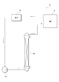
- FIG. 1 is a block diagram illustrating a schematic configuration of the engine cooling device according to the first embodiment.
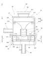
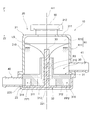
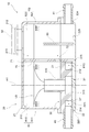
- FIG. 2 is a sectional view showing a sectional structure of the reserve tank of the first embodiment.
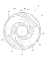
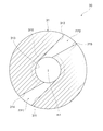
- FIG. 3 is a cross-sectional view showing a cross-sectional structure of the flow path forming plate along the line III-III in FIG.
- FIG. 4 is a cross-sectional view showing a cross-sectional structure of the flow path forming plate along the line IV-IV in FIG.
- FIG. 5 is a cross-sectional view illustrating a cross-sectional structure of a distal end portion of a cylindrical portion according to a modification of the first embodiment.
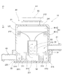
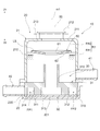
- FIG. 6 is a cross-sectional view illustrating a cross-sectional structure of the reserve tank according to the second embodiment.
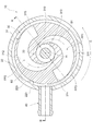
- FIG. 7 is a cross-sectional view showing a cross-sectional structure along the line VII-VII of FIG.
- FIG. 8 is a cross-sectional view illustrating a cross-sectional structure of the reserve tank according to the third embodiment.
- FIG. 9 is a cross-sectional view showing a cross-sectional structure along the line IX-IX in FIG.
- FIG. 10 is a cross-sectional view illustrating a cross-sectional structure around a distal end portion of a cylindrical portion of a reserve tank according to a fourth embodiment.
- FIG. 11 is a front view showing a front structure of a rod-shaped member according to a modification of the fourth embodiment.
- FIG. 12 is a cross-sectional view illustrating a cross-sectional structure of a flow path forming plate according to the fifth embodiment.
- FIG. 13 is a cross-sectional view illustrating a cross-sectional structure of a flow path forming plate according to the sixth embodiment.
- FIG. 14 is a cross-sectional view illustrating a cross-sectional structure of the reserve tank according to the seventh embodiment.
- FIG. 15 is a cross-sectional view illustrating a cross-sectional structure of the reserve tank according to the eighth embodiment.
- FIG. 16 is a cross-sectional view illustrating a cross-sectional structure of the reserve tank according to the ninth embodiment.
- FIG. 17 is a block diagram illustrating a schematic configuration of an electric system cooling device according to another embodiment.
- the engine cooling device 1 shown in FIG. 1 is a device for cooling an engine 2 of a vehicle to an appropriate temperature.
- the engine cooling device 1 has a structure in which an engine 2, a pump 3, and a radiator 4 are connected in a ring shape.
- cooling water pumped by a pump 3 circulates through an engine 2 and a radiator 4.
- the engine 2 is cooled by supplying the cooling water cooled in the radiator 4 to the engine 2.
- a reserve tank 10 is arranged in parallel with a path connecting the cylinder head of the engine 2 and the upper tank of the radiator 4 in such a circulation path of the cooling water.
- a part of the cooling water flows from the cylinder head of the engine 2 into the reserve tank 10 and is stored therein.
- the reserve tank 10 separates gas such as bubbles in the cooling water and stores the cooling water.
- the cooling water stored in the reserve tank 10 is supplied to the upper tank of the radiator 4 by the operation of the pump 3.
- the liquid and the gas separated by the reserve tank 10 of the present embodiment are the cooling water and the gas contained in the cooling water, respectively.
- the reserve tank 10 includes a tank body 20 and a flow path forming plate 30 housed inside the tank body 20.
- the direction indicated by arrow Z1 indicates a vertically upward direction
- the direction indicated by arrow Z2 indicates a vertically downward direction.
- the tank body 20 is formed in a cylindrical shape around the axis m1.
- the tank body 20 is configured to be divided into an upper tank portion 21 and a lower tank portion 22 in a direction along the axis m1.
- the tank body 20 is configured by joining an upper tank portion 21 and a lower tank portion 22.
- the tank main body 20 is formed of a resin material or the like. If a resin material such as polypropylene having permeability is used as the material of the tank body 20, the water level of the cooling water inside the tank body 20 can be visually checked.
- a channel forming plate 30 is housed inside the lower tank portion 22.
- a groove 222 into which the outer peripheral portion of the flow path forming plate 30 is fitted is formed on the inner peripheral surface of the lower tank portion 22.
- the upper surface of the outer peripheral portion of the flow path forming plate 30 fitted into the groove 222 is pressed by the upper tank portion 21 so that the flow path forming plate 30 is fixed to the tank body 20.
- a plurality of ribs for supporting the bottom surface of the flow path forming plate 30 are formed on the inner peripheral surface of the lower tank portion 22, and the plurality of ribs and the upper tank portion 21 form a flow path.
- the channel forming plate 30 may be fixed to the tank body 20 by sandwiching the outer peripheral portion of the forming plate 30.
- An inflow pipe 40 for flowing cooling water into the tank body 20 is attached to the bottom wall 221 of the lower tank 22.
- a gas-liquid separation chamber R1 is formed inside the upper tank portion 21 for separating bubbles contained in the cooling water and storing the cooling water.
- the symbol R10 in the figure indicates a gas layer in which gas mainly exists in the gas-liquid separation chamber R1
- the symbol R11 in the figure indicates a liquid layer in which cooling water mainly exists in the gas-liquid separation chamber R1.
- the gas-liquid separation chamber R1 is formed as a space defined by the inner wall surface of the upper tank portion 21 and the upper surface of the flow path forming plate 30.
- An outflow pipe 41 for flowing out the cooling water stored in the gas-liquid separation chamber R1 to the outside is attached to the side wall 210 of the upper tank section 21.
- the outflow pipe 41 has its internal flow path located below the liquid level LS of the cooling water stored in the gas-liquid separation chamber R1 and its internal flow path located below the tip of the cylindrical portion 310. It is arranged to be.
- a cylindrical water inlet 212 for injecting cooling water into the tank body 20 is formed in the upper wall 211 of the upper tank 21.
- a pressure cap 50 is attached to the water inlet 212. The pressure applied to each part of the engine cooling device 1 including the inside of the tank body 20 can be adjusted to a predetermined pressure by the pressure cap 50.
- the flow path forming plate 30 includes an upper plate 31 and a lower plate 32.
- the upper plate 31 is formed in a column shape around the axis m1.
- a cylindrical portion 310 formed into a cylindrical shape with the axis m1 as a central axis is formed so as to extend into the gas-liquid separation chamber R1. That is, the cylindrical portion 310 is arranged inside the tank body 20.
- the upper plate 31 defines the gas-liquid separation chamber R1 together with the inner wall surface of the upper tank portion 21.
- concave grooves 311 and 312 for forming two independent flow paths FP1 and FP2 are formed inside the upper plate 31.
- the concave grooves 311 and 312 are formed so as to be bent in an arc shape from a radial outside centered on the axis m ⁇ b> 1 toward the center of the upper plate 31.
- the concave grooves 311 and 312 join at a joining portion 313 formed of a space formed in a central portion of the upper plate 31.
- the junction 313 is communicated from one end of the cylindrical portion 310 to the inside of the cylindrical portion 310.
- the concave grooves 311 and 312 are formed such that their widths become smaller from the outside of the junction 313 toward the junction 313 in the radial direction around the axis m1.
- the lower plate 32 is assembled to the bottom surface of the upper plate 31.
- the lower plate 32 closes the respective openings of the concave grooves 311, 312 and the junction 313 formed in the upper plate 31.
- the space surrounded by the lower plate 32 and the concave groove 311 of the upper plate 31 constitutes a first flow path FP1.
- the space surrounded by the lower plate 32 and the concave groove 312 of the upper plate 31 constitutes a second flow path FP2.
- the inlets 320 and 321 are formed in the outer edge portion of the lower plate 32 at positions symmetrical with respect to the axis m1.
- the inflow port 320 is a portion for introducing the cooling water flowing from the inflow pipe 40 into the first flow path FP1.
- the inflow port 321 is a part for introducing the cooling water flowing from the inflow pipe 40 into the second flow path FP2.
- the cooling water flowing from the inflow pipe 40 flows into the first flow path FP1 and the second flow path FP2 through the inflow ports 320 and 321 of the flow path forming plate 30, respectively.
- the flow direction B1 of the fluid flowing from the first flow path FP1 to the junction 313 and the flow direction B2 of the fluid flowing from the second flow path FP2 to the junction 313 are opposed to each other. are doing.
- a swirling flow can be generated in the cooling water of the junction 313.
- the swirling cooling water flows upward while swirling inside the cylindrical portion 310 as shown by an arrow B3 in FIG. 2, and is discharged from the tip of the cylindrical portion 310 to the gas-liquid separation chamber R1. .
- a vortex of the cooling water is formed in the gas-liquid separation chamber R1.
- bubbles included in the cooling water gather near the center of the gas-liquid separation chamber R1.
- Bubbles collected near the center of the gas-liquid separation chamber R1 accumulate above the gas-liquid separation chamber R1. Therefore, a gas layer R10 is formed above the gas-liquid separation chamber R1, and a liquid layer R11 is formed below the gas layer R10.
- the cooling water stored in the liquid layer R11 flows out through the outflow pipe 41.
- the flow paths FP1 and FP2 are formed point-symmetrically about the junction 313 so that cooling water flows from the outside of the junction 313 toward the junction 313 in the radial direction about the axis m1.
- the joining portion 313 is provided at one end of the cylindrical portion 310, and joins the cooling water flowing through the flow paths FP1 and FP2 to flow into one end of the cylindrical portion 310.
- the cooling water flowing into the inside of the cylindrical portion 310 from the joining portion 313 flows into the gas-liquid separation chamber R1 from the other end of the cylindrical portion 310.
- a swirl flow can be generated in the cooling water at the junction 313 by the flows of the cooling water flowing through the flow paths FP1 and FP2, respectively.
- a swirling flow is easily generated in the cooling water. Therefore, the flow rate of the cooling water required to generate a swirling flow in the cooling water can be reduced, and as a result, the load on the pump 3 can be reduced. If the cooling water flowing from the inflow pipe 40 into the tank main body 20 can flow into the flow paths FP1 and FP2, the position and direction of the inflow pipe 40 in the tank main body 20 can be freely changed. Therefore, it is possible to increase the degree of freedom in setting the position and installation direction of the inflow pipe 40.
- a cylindrical portion 310 is formed at the center of the upper surface, which is the outer surface facing the gas-liquid separation chamber R1 in the flow path forming plate 30.
- the inflow pipe 40 is provided on the bottom wall 221 of the tank body 20 facing the bottom of the flow path forming plate 30. According to such a configuration, as compared with the case where the inflow pipes 40 are provided in the side wall portions 210 and 220 of the tank body 20, it is possible to avoid an increase in the size of the tank body 20 radially outward around the axis m1. Can be.
- the flow paths FP1 and FP2 are formed so as to swirl and flow the cooling water from the outside of the junction 313 toward the junction 313 in the radial direction about the axis m1. According to such a configuration, a swirling flow is more easily generated in the cooling water flowing from the flow paths FP1 and FP2 into the junction 313, so that the load on the pump 3 can be further reduced.
- the flow paths FP1 and FP2 are formed such that the flow path cross-sectional area becomes smaller from the outside of the junction 313 toward the junction 313 in the radial direction around the axis m1. Thereby, the flow velocity of the cooling water flowing in the flow paths FP1 and FP2 becomes faster as going from the outside of the junction 313 to the junction 313, so that the swirling flow is applied to the cooling water flowing from the flow paths FP1 and FP2 into the junction 313. Further, it is easy to generate. Therefore, the load on the pump 3 can be further reduced.
- the inflow pipe 40 is provided on the side wall 220 of the lower tank portion 22 of the tank main body 20. It is different from the reserve tank 10.
- the cooling water flowing from the inflow pipe 40 flows into each of the flow paths FP1 and FP2 from the outer peripheral portion of the flow path forming plate 30.
- the flow path forming plate 30 is fixed to the tank body 20 by its outer peripheral portion being sandwiched between the bottom wall portion 221 of the lower tank portion 22 and the upper tank portion 21. Have been. As shown in FIG. 6, an annular gap is formed between the outer wall of the flow path forming plate 30 and the inner wall of the lower tank 22. This gap forms an outer peripheral channel FP3 into which the cooling water flows from the inflow pipe 40.
- an inflow port 314 for flowing the cooling water flowing through the outer flow path FP3 into the first flow path FP1, and the second cooling water flowing through the outer flow path FP3 are provided on the outer peripheral surface of the upper plate 31 of the flow path forming plate 30, an inflow port 314 for flowing the cooling water flowing through the outer flow path FP3 into the first flow path FP1, and the second cooling water flowing through the outer flow path FP3 are provided.
- An inflow port 315 for flowing into the flow path FP2 is formed.
- the inflow port 314 and the inflow port 315 are arranged point-symmetrically about the junction 313.
- a projection 223 is formed on the inner wall of the lower tank 22 so as to cross the outer peripheral flow path FP3.
- the protrusion 223 is provided to regulate the flow direction of the cooling water flowing from the inflow pipe 40 into the outer peripheral flow path FP3 in the circumferential direction indicated by the arrow C in the drawing.
- the direction indicated by the arrow C is a direction of orbiting around the axis m1 in the order of the inflow pipe 40, the inflow port 314 of the first flow path FP1, and the inflow port 314 of the second flow path FP2.
- the functions and effects shown in the following (5) are obtained.
- the inflow pipe 40 is provided on the side wall 220 of the tank body 20 facing the outer peripheral surface of the flow path forming plate 30. Thereby, compared to the case where the inflow pipe 40 is provided on the bottom wall portion 221 of the tank main body 20 as in the reserve tank 10 of the first embodiment, it is possible to avoid an increase in the size of the tank main body 20 in the axial direction. .
- a cylindrical rod-shaped member 33 is disposed inside a cylindrical portion 310.
- the rod-shaped member 33 may be formed in a tubular shape.
- the rod-shaped member 33 is formed so as to extend upward along the axis m1 from the center of the lower plate 32.
- the rod-shaped member 33 is formed so as to extend through the inside of the cylindrical portion 310 to the inside of the gas-liquid separation chamber R1.
- the rod-shaped member 33 is arranged coaxially with the cylindrical portion 310.
- the tip of the rod-shaped member 33 extends into the gas-liquid separation chamber R1 more than the tip of the cylindrical portion 310.
- the operation and effect shown in the following (6) can be further obtained.
- (6) In the reserve tank 10 of the present embodiment, since the cooling water flowing into the cylindrical portion 310 flows along the outer peripheral surface of the rod-shaped member 33, a swirling flow is easily generated in the cooling water flowing in the cylindrical portion 310. Become. This makes it possible to reduce the flow rate of the cooling water required to generate the swirling flow in the cooling water, so that the load on the pump for pumping the cooling water to the reserve tank can be further reduced.
- a reserve tank 10 according to a fourth embodiment will be described.
- a description will be given focusing on differences from the reserve tank 10 of the third embodiment.
- a protrusion 330 is formed on the outer peripheral surface of the rod-shaped member 33.
- the protrusion 330 is formed on the outer peripheral surface of the rod-shaped member 33 at a position facing the tip of the cylindrical portion 310.
- Bubbles contained in the cooling water flowing along the rod-shaped member 33 hit the projections 330, so that the bubbles are easily separated from the cooling water.
- the projection 330 is formed on the outer peripheral surface of the rod-shaped member 33 at a position facing the tip of the cylindrical portion 310, when the cooling water is discharged from the inside of the cylindrical portion 310 to the gas-liquid separation chamber R1. Since the bubbles included in the cooling water are separated by the projections 330, the bubbles can be more efficiently separated from the cooling water.
- a fifth embodiment of the reserve tank 10 will be described.
- the upper plate 31 shown in FIG. 12 is used.
- concave grooves 311 and 312 are formed in the upper plate 31 of the present embodiment so as to extend linearly from the outside of the junction 313 toward the junction 313 in the radial direction about the axis m1. Is formed.
- One side wall of each of the concave grooves 311 and 312 is formed to extend in a tangential direction of the inner wall surface of the cylindrical portion 310.
- each of the concave grooves 311 and 312 is formed so as to be separated from the one side wall portion toward the outer periphery of the upper plate 31.
- the concave grooves 311 and 312 are formed such that their width becomes narrower toward the outside of the junction 313 in the radial direction around the axis m1.
- the functions and effects shown in the following (8) are obtained.
- the flow paths FP1 and FP2 are formed so that the cooling water flows linearly from the outside of the junction 313 toward the junction 313 in the radial direction about the axis m1. According to such a configuration, as compared with the case where the arc-shaped flow paths FP1 and FP2 are formed in the flow path forming plate 30 as in the first embodiment, the manufacture of the flow path forming plate 30 is facilitated.
- a reserve tank 10 according to a sixth embodiment will be described.
- the upper plate 31 shown in FIG. 13 is used.
- concave grooves 316 and 317 are further formed in the upper plate 31 of the present embodiment.
- the concave grooves 316 and 317 are formed point-symmetrically about the junction 313.
- the concave grooves 311, 312, 316, and 317 are formed at equal intervals in the circumferential direction around the axis m ⁇ b> 1.
- the space surrounded by these concave grooves 311, 312, 316, and 317 and the lower plate 32 forms flow paths FP1, FP2, FP4, and FP5.
- the operation and effect shown in the following (9) can be further obtained.
- the number of flow paths formed in the flow path forming plate 30 is increased as compared with the reserve tank 10 of the second embodiment. In this case, a swirling flow is more easily generated. This makes it possible to reduce the flow rate of the cooling water required to generate the swirling flow in the cooling water, so that the load on the pump for pumping the cooling water to the reserve tank can be further reduced.
- the reserve tank 10 of the present embodiment further includes a floating plate 60 arranged so as to float on the liquid level LS of the cooling water stored in the gas-liquid separation chamber R1.
- the floating plate 60 is formed of a resin material having a lower specific gravity than the cooling water so that the floating plate 60 can float on the liquid level LS of the cooling water.
- the floating plate 60 is formed in a disk shape around the axis m1.
- a through hole 61 is formed in the center of the floating plate 60.
- the bottom surface 62 of the floating plate 60 is tapered such that a portion located on the outer peripheral portion of the floating plate 60 is closer to the ceiling surface 213 of the gas-liquid separation chamber R1 than a portion located at the central portion of the floating plate 60. It is formed in a shape.
- the functions and effects shown in the above (10) and (11) can be further obtained.
- the floating plate 60 stays while rotating on the vortex of the cooling water formed in the gas-liquid separation chamber R1. Bubbles contained in the cooling water discharged from the tip of the cylindrical portion 310 move upward in the gas-liquid separation chamber R1 and adhere to the bottom surface 62 of the floating plate 60. Therefore, bubbles contained in the cooling water are collected on the bottom surface 62 of the floating plate 60. Further, since the floating plate 60 itself is rotating, the air bubbles collected on the bottom surface 62 of the floating plate 60 move toward the outer periphery of the floating plate 60 by centrifugal force and move to the gas layer R10 of the gas-liquid separation chamber R1. Will be released. Therefore, the bubbles contained in the cooling water can be more accurately guided to the gas layer R10 of the gas-liquid separation chamber R1, and the bubbles contained in the cooling water can be further easily separated.
- the reserve tank 10 is tilted so that the axis m1 forms a predetermined angle with respect to the vertical direction, so that the liquid level LS of the cooling water in the gas-liquid separation chamber R1 is increased. May tilt. Further, when the vehicle is traveling on a rough road, the reserve tank 10 vibrates, so that the liquid level LS of the cooling water in the gas-liquid separation chamber R1 may be similarly inclined. When the liquid level LS of the cooling water in the gas-liquid separation chamber R1 is disturbed in this way, there is a concern that the gas present in the gas layer R10 may be mixed into the cooling water in the liquid layer R11.
- the liquid level LS of the cooling water in the gas-liquid separation chamber R1 is less likely to be disturbed by the floating plate 60 floating on the liquid level LS of the cooling water in the gas-liquid separation chamber R1.
- the gas existing in the gas layer R10 is less likely to be mixed into the cooling water in the liquid layer R11.
- a reserve tank 10 according to an eighth embodiment will be described.
- a description will be given focusing on differences from the reserve tank 10 of the second embodiment.
- a storage chamber R2 is further disposed inside the tank main body 20 of the present embodiment so as to be adjacent to the gas-liquid separation chamber R1 with a partition wall 70 interposed therebetween.
- Reference numeral R20 in the figure indicates a gas layer in the storage room R2, and reference numeral R21 indicates a liquid layer in the storage room R2.
- the partition 70 has gas introduction holes 71 for introducing gas present in the gas layer R10 of the gas-liquid separation chamber R1 into the gas layer R20 of the storage chamber R2, and cooling gas existing in the liquid layer R11 of the gas-liquid separation chamber R1.
- a liquid introduction hole 72 for introducing water into the liquid layer R21 of the storage chamber R2 is formed.
- An outflow pipe 41 for allowing the cooling water stored in the liquid layer R21 of the storage chamber R2 to flow out to the outside is provided on the side wall portion 224 of the tank body 20 located on the opposite side of the storage chamber R2 with respect to the partition wall 70. Installed.
- the operation and effect shown in the following (12) can be further obtained. (12) Since the cooling water and the gas can be further stored in the storage chamber R2, the size of the reserve tank 10 can be increased.
- the tank main body 20 of the present embodiment further includes a partition plate 80 arranged inside the storage chamber R2 in parallel with the partition wall 70.
- the partition plate 80 extends halfway from the bottom surface 225 of the storage room R2 toward the ceiling surface 213 of the storage room R2 such that the tip end is located closer to the ceiling surface 213 of the storage room than the liquid introduction hole 72 of the partition wall 70. It is formed as follows.
- the operation and effect shown in the following (13) can be further obtained.
- (13) Even if the cooling water flowing into the storage chamber R2 from the gas-liquid separation chamber R1 through the liquid introduction hole 72 contains bubbles, the cooling water containing the bubbles hits the partition plate 80. Thereby, the cooling water and the bubbles can be separated. This makes it difficult to cause a situation in which the cooling water containing bubbles is discharged to the outside through the outflow pipe 41.
- the reserve tank 10 of each embodiment may use a liquid other than the cooling water of the engine of the vehicle.
- the reserve tank 10 of each embodiment is not limited to the engine cooling device 1 and can be applied to, for example, an electric cooling device that cools an inverter, a battery, a motor, and the like mounted on an electric vehicle.
- the electric cooling device 1a mounted on the electric vehicle includes a pump 3a, a radiator 4a, a heat exchanger (HE: Heat Exchanger) 5, and a reserve tank 10. It has.
- the first cooling water circulates through these elements.
- the first cooling water cooled by the radiator 4a is supplied to the heat exchanger 5.
- the heat exchanger 5 is supplied with second cooling water for cooling an electric system such as an inverter, a battery, and a motor.
- the heat exchanger 5 cools the second cooling water by performing heat exchange between the first cooling water and the second cooling water.
- the first cooling water discharged from the heat exchanger 5 flows into the reserve tank 10.
- the reserve tank 10 separates gas such as bubbles in the first cooling water and stores the cooling water. It is possible to use the reserve tank 10 of each embodiment for the reserve tank 10 provided in such an electric system cooling device 1a.
- the reserve tank 10 of each embodiment can be applied to a configuration in which all of the cooling water flowing through the cooling circuit flows, such as the electric system cooling device 1a shown in FIG.
- the present disclosure is not limited to the above specific examples.
- the above-described specific examples in which a person skilled in the art appropriately changes the design are also included in the scope of the present disclosure as long as they have the features of the present disclosure.
- the components included in each of the specific examples described above, and their arrangement, conditions, shapes, and the like are not limited to those illustrated, but can be appropriately changed.
- the elements included in each of the specific examples described above can be appropriately changed in combination as long as there is no technical contradiction.
Landscapes
- Engineering & Computer Science (AREA)
- Chemical & Material Sciences (AREA)
- Chemical Kinetics & Catalysis (AREA)
- Combustion & Propulsion (AREA)
- Mechanical Engineering (AREA)
- General Engineering & Computer Science (AREA)
- Degasification And Air Bubble Elimination (AREA)
Applications Claiming Priority (2)
| Application Number | Priority Date | Filing Date | Title |
|---|---|---|---|
| JP2018-126016 | 2018-07-02 | ||
| JP2018126016A JP7063149B2 (ja) | 2018-07-02 | 2018-07-02 | リザーブタンク |
Publications (1)
| Publication Number | Publication Date |
|---|---|
| WO2020009030A1 true WO2020009030A1 (ja) | 2020-01-09 |
Family
ID=69060951
Family Applications (1)
| Application Number | Title | Priority Date | Filing Date |
|---|---|---|---|
| PCT/JP2019/025859 Ceased WO2020009030A1 (ja) | 2018-07-02 | 2019-06-28 | リザーブタンク |
Country Status (2)
| Country | Link |
|---|---|
| JP (1) | JP7063149B2 (https=) |
| WO (1) | WO2020009030A1 (https=) |
Families Citing this family (2)
| Publication number | Priority date | Publication date | Assignee | Title |
|---|---|---|---|---|
| DE112021002336T5 (de) * | 2020-04-15 | 2023-01-26 | Denso Corporation | Reservebehälter |
| JP7287377B2 (ja) * | 2020-04-15 | 2023-06-06 | 株式会社デンソー | リザーブタンク |
Citations (10)
| Publication number | Priority date | Publication date | Assignee | Title |
|---|---|---|---|---|
| JPS5267067A (en) * | 1975-10-30 | 1977-06-03 | Enso Gutzeit Oy | Hydroocyclone device |
| JPS5843909U (ja) * | 1981-09-18 | 1983-03-24 | トキコ株式会社 | 気液分離装置 |
| EP0155553A2 (de) * | 1984-03-08 | 1985-09-25 | FÜLLPACK GmbH & Co. | Einrichtung zur Behandlung einer stark schaumbildenden Flüssigkeit mit einem Gas |
| JPH1043293A (ja) * | 1996-08-08 | 1998-02-17 | Senko Ika Kogyo Kk | 液体中気泡除去装置 |
| JP2000312840A (ja) * | 1999-04-28 | 2000-11-14 | Gijutsu Kaihatsu Sogo Kenkyusho:Kk | 混合流体における重質成分及び軽質成分の分離装置 |
| JP2001304402A (ja) * | 2000-04-20 | 2001-10-31 | Hitachi Ltd | 自動変速機 |
| US20050224021A1 (en) * | 2002-07-12 | 2005-10-13 | Dirk Kastell | Compensation reservoir for a cooling circuit of an internal combustion engine |
| JP2015028336A (ja) * | 2013-06-24 | 2015-02-12 | トヨタ車体株式会社 | エンジン冷却水のリザーバタンク |
| WO2017056475A1 (ja) * | 2015-09-28 | 2017-04-06 | 本田技研工業株式会社 | エクスパンションタンク |
| JP2017166347A (ja) * | 2016-03-14 | 2017-09-21 | 株式会社デンソー | リザーブタンク |
Family Cites Families (2)
| Publication number | Priority date | Publication date | Assignee | Title |
|---|---|---|---|---|
| JP3588771B2 (ja) | 1999-11-18 | 2004-11-17 | 佐藤樹脂工業株式会社 | 気泡除去装置 |
| JP5962708B2 (ja) | 2014-06-10 | 2016-08-03 | 横河電機株式会社 | 脱泡槽 |
-
2018
- 2018-07-02 JP JP2018126016A patent/JP7063149B2/ja active Active
-
2019
- 2019-06-28 WO PCT/JP2019/025859 patent/WO2020009030A1/ja not_active Ceased
Patent Citations (10)
| Publication number | Priority date | Publication date | Assignee | Title |
|---|---|---|---|---|
| JPS5267067A (en) * | 1975-10-30 | 1977-06-03 | Enso Gutzeit Oy | Hydroocyclone device |
| JPS5843909U (ja) * | 1981-09-18 | 1983-03-24 | トキコ株式会社 | 気液分離装置 |
| EP0155553A2 (de) * | 1984-03-08 | 1985-09-25 | FÜLLPACK GmbH & Co. | Einrichtung zur Behandlung einer stark schaumbildenden Flüssigkeit mit einem Gas |
| JPH1043293A (ja) * | 1996-08-08 | 1998-02-17 | Senko Ika Kogyo Kk | 液体中気泡除去装置 |
| JP2000312840A (ja) * | 1999-04-28 | 2000-11-14 | Gijutsu Kaihatsu Sogo Kenkyusho:Kk | 混合流体における重質成分及び軽質成分の分離装置 |
| JP2001304402A (ja) * | 2000-04-20 | 2001-10-31 | Hitachi Ltd | 自動変速機 |
| US20050224021A1 (en) * | 2002-07-12 | 2005-10-13 | Dirk Kastell | Compensation reservoir for a cooling circuit of an internal combustion engine |
| JP2015028336A (ja) * | 2013-06-24 | 2015-02-12 | トヨタ車体株式会社 | エンジン冷却水のリザーバタンク |
| WO2017056475A1 (ja) * | 2015-09-28 | 2017-04-06 | 本田技研工業株式会社 | エクスパンションタンク |
| JP2017166347A (ja) * | 2016-03-14 | 2017-09-21 | 株式会社デンソー | リザーブタンク |
Also Published As
| Publication number | Publication date |
|---|---|
| JP2020002935A (ja) | 2020-01-09 |
| JP7063149B2 (ja) | 2022-05-09 |
Similar Documents
| Publication | Publication Date | Title |
|---|---|---|
| CN107208985B (zh) | 换热器和具有换热器的空气技术设备 | |
| CN103609003B (zh) | 冷却壳和用于冷却壳的偏转单元 | |
| WO2020009030A1 (ja) | リザーブタンク | |
| CN108351175A (zh) | 热交换器 | |
| JP2015028336A (ja) | エンジン冷却水のリザーバタンク | |
| US1020699A (en) | Centrifugal pump. | |
| JP2017166347A (ja) | リザーブタンク | |
| KR20220029441A (ko) | 유체 전달 회로를 위한 와류 분리 장치 | |
| US6840386B2 (en) | Unitary centertube for a fluid filter | |
| JPH1147639A (ja) | 軸受の冷却装置および冷却方法 | |
| JP7227865B2 (ja) | リザーバタンク | |
| JP2021169815A (ja) | リザーブタンク | |
| CN209006693U (zh) | 数控车床一体箱式水冷电主轴 | |
| JP2913117B2 (ja) | 多段エジェクターポンプ | |
| JP2012187439A (ja) | イオン交換器 | |
| JP2718969B2 (ja) | ポンプ | |
| CN201836108U (zh) | 泵叶轮 | |
| WO2021210283A1 (ja) | リザーブタンク | |
| JP4332495B2 (ja) | 自動車両のオイル循環路内の分離装置 | |
| JP2020067081A (ja) | リザーブタンク | |
| CN115207398B (zh) | 去离子器 | |
| JP2013163149A (ja) | エマルション成形用マイクロリアクタ | |
| CN105782478A (zh) | 一种具有过滤功能的阀门 | |
| US20220307744A1 (en) | Reservoir tank | |
| JP2020002935A5 (https=) |
Legal Events
| Date | Code | Title | Description |
|---|---|---|---|
| 121 | Ep: the epo has been informed by wipo that ep was designated in this application |
Ref document number: 19830870 Country of ref document: EP Kind code of ref document: A1 |
|
| NENP | Non-entry into the national phase |
Ref country code: DE |
|
| 122 | Ep: pct application non-entry in european phase |
Ref document number: 19830870 Country of ref document: EP Kind code of ref document: A1 |