WO2020009030A1 - リザーブタンク - Google Patents
リザーブタンク Download PDFInfo
- Publication number
- WO2020009030A1 WO2020009030A1 PCT/JP2019/025859 JP2019025859W WO2020009030A1 WO 2020009030 A1 WO2020009030 A1 WO 2020009030A1 JP 2019025859 W JP2019025859 W JP 2019025859W WO 2020009030 A1 WO2020009030 A1 WO 2020009030A1
- Authority
- WO
- WIPO (PCT)
- Prior art keywords
- liquid
- gas
- reserve tank
- flow
- flow path
- Prior art date
Links
Images


Classifications
-
- B—PERFORMING OPERATIONS; TRANSPORTING
- B01—PHYSICAL OR CHEMICAL PROCESSES OR APPARATUS IN GENERAL
- B01D—SEPARATION
- B01D19/00—Degasification of liquids
-
- F—MECHANICAL ENGINEERING; LIGHTING; HEATING; WEAPONS; BLASTING
- F01—MACHINES OR ENGINES IN GENERAL; ENGINE PLANTS IN GENERAL; STEAM ENGINES
- F01P—COOLING OF MACHINES OR ENGINES IN GENERAL; COOLING OF INTERNAL-COMBUSTION ENGINES
- F01P11/00—Component parts, details, or accessories not provided for in, or of interest apart from, groups F01P1/00 - F01P9/00
Definitions
- the present disclosure relates to a reserve tank that separates gas in a liquid and stores the liquid.
- the reserve tank described in Patent Literature 1 includes a cylindrical gas-liquid separation chamber therein. At the bottom of the gas-liquid separation chamber, there is provided an inflow port whose cooling water inflow direction is tangential to the gas-liquid separation chamber. Inside the gas-liquid separation chamber, there is arranged a cylindrical separator whose diameter decreases toward the top. In this reserve tank, the gas in the cooling water is separated by the rising of the cooling water flowing into the separator from the inflow port while rotating along the inner wall surface of the separator.
- the flow rate of the cooling water from the inlet to the inner wall surface of the separator needs to be equal to or higher than a predetermined speed.
- the pressure of the cooling water flowing into the inlet needs to be equal to or higher than the predetermined pressure, so that the load of the pump for pumping the cooling water to the reserve tank increases.
- An object of the present disclosure is to provide a reserve tank that can reduce the load on a pump that pumps a liquid and can increase the degree of freedom in setting the position and installation direction of an inflow pipe.
- a reserve tank includes a tank body, a cylindrical portion, a plurality of flow paths, an inflow pipe, and a junction.
- the tank main body has therein a gas-liquid separation chamber for separating gas in the liquid and storing the liquid.
- the cylindrical portion is disposed inside the tank main body, and is formed in a cylindrical shape around a predetermined axis.
- the plurality of flow paths are formed independently of the flow of the liquid.
- the inflow pipe is attached to the tank main body, and allows the liquid to flow from the outside of the tank main body to the plurality of flow paths.
- the joining portion is provided at one end of the cylindrical portion, and joins the liquids flowing through the plurality of flow paths, respectively, to flow into one end of the cylindrical portion.
- the plurality of flow paths are formed point-symmetrically about the junction so that the liquid flows from the outside of the junction toward the junction in the radial direction about the axis.
- the liquid that has flowed into the cylindrical portion from the junction flows into the gas-liquid separation chamber from the other end of the cylindrical portion.
- the liquids flowing through the plurality of flow paths respectively merge at the merging portion and flow into the cylindrical portion.
- a swirling flow can be generated in the liquid at the merging portion by the flow of the liquid flowing into the merging portion from the plurality of flow paths, a swirling flow is generated by the flow of the liquid flowing from one inlet.
- the swirl flow is more likely to be generated in the fluid as compared to the reserve tank described above. Therefore, the flow velocity of the liquid required to generate a swirling flow in the liquid can be reduced, and as a result, the load on the pump for pumping the liquid to the reserve tank can be reduced.
- the position and installation direction of the inflow pipe in the tank body can be freely changed. Therefore, the degree of freedom in setting the position and the installation direction of the inflow pipe can be increased.
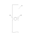
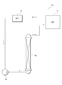
- FIG. 1 is a block diagram illustrating a schematic configuration of the engine cooling device according to the first embodiment.
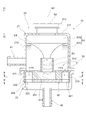
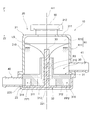
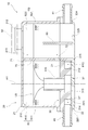
- FIG. 2 is a sectional view showing a sectional structure of the reserve tank of the first embodiment.
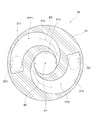
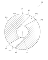
- FIG. 3 is a cross-sectional view showing a cross-sectional structure of the flow path forming plate along the line III-III in FIG.
- FIG. 4 is a cross-sectional view showing a cross-sectional structure of the flow path forming plate along the line IV-IV in FIG.
- FIG. 5 is a cross-sectional view illustrating a cross-sectional structure of a distal end portion of a cylindrical portion according to a modification of the first embodiment.
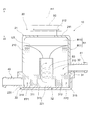
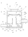
- FIG. 6 is a cross-sectional view illustrating a cross-sectional structure of the reserve tank according to the second embodiment.
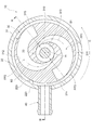
- FIG. 7 is a cross-sectional view showing a cross-sectional structure along the line VII-VII of FIG.
- FIG. 8 is a cross-sectional view illustrating a cross-sectional structure of the reserve tank according to the third embodiment.
- FIG. 9 is a cross-sectional view showing a cross-sectional structure along the line IX-IX in FIG.
- FIG. 10 is a cross-sectional view illustrating a cross-sectional structure around a distal end portion of a cylindrical portion of a reserve tank according to a fourth embodiment.
- FIG. 11 is a front view showing a front structure of a rod-shaped member according to a modification of the fourth embodiment.
- FIG. 12 is a cross-sectional view illustrating a cross-sectional structure of a flow path forming plate according to the fifth embodiment.
- FIG. 13 is a cross-sectional view illustrating a cross-sectional structure of a flow path forming plate according to the sixth embodiment.
- FIG. 14 is a cross-sectional view illustrating a cross-sectional structure of the reserve tank according to the seventh embodiment.
- FIG. 15 is a cross-sectional view illustrating a cross-sectional structure of the reserve tank according to the eighth embodiment.
- FIG. 16 is a cross-sectional view illustrating a cross-sectional structure of the reserve tank according to the ninth embodiment.
- FIG. 17 is a block diagram illustrating a schematic configuration of an electric system cooling device according to another embodiment.
- the engine cooling device 1 shown in FIG. 1 is a device for cooling an engine 2 of a vehicle to an appropriate temperature.
- the engine cooling device 1 has a structure in which an engine 2, a pump 3, and a radiator 4 are connected in a ring shape.
- cooling water pumped by a pump 3 circulates through an engine 2 and a radiator 4.
- the engine 2 is cooled by supplying the cooling water cooled in the radiator 4 to the engine 2.
- a reserve tank 10 is arranged in parallel with a path connecting the cylinder head of the engine 2 and the upper tank of the radiator 4 in such a circulation path of the cooling water.
- a part of the cooling water flows from the cylinder head of the engine 2 into the reserve tank 10 and is stored therein.
- the reserve tank 10 separates gas such as bubbles in the cooling water and stores the cooling water.
- the cooling water stored in the reserve tank 10 is supplied to the upper tank of the radiator 4 by the operation of the pump 3.
- the liquid and the gas separated by the reserve tank 10 of the present embodiment are the cooling water and the gas contained in the cooling water, respectively.
- the reserve tank 10 includes a tank body 20 and a flow path forming plate 30 housed inside the tank body 20.
- the direction indicated by arrow Z1 indicates a vertically upward direction
- the direction indicated by arrow Z2 indicates a vertically downward direction.
- the tank body 20 is formed in a cylindrical shape around the axis m1.
- the tank body 20 is configured to be divided into an upper tank portion 21 and a lower tank portion 22 in a direction along the axis m1.
- the tank body 20 is configured by joining an upper tank portion 21 and a lower tank portion 22.
- the tank main body 20 is formed of a resin material or the like. If a resin material such as polypropylene having permeability is used as the material of the tank body 20, the water level of the cooling water inside the tank body 20 can be visually checked.
- a channel forming plate 30 is housed inside the lower tank portion 22.
- a groove 222 into which the outer peripheral portion of the flow path forming plate 30 is fitted is formed on the inner peripheral surface of the lower tank portion 22.
- the upper surface of the outer peripheral portion of the flow path forming plate 30 fitted into the groove 222 is pressed by the upper tank portion 21 so that the flow path forming plate 30 is fixed to the tank body 20.
- a plurality of ribs for supporting the bottom surface of the flow path forming plate 30 are formed on the inner peripheral surface of the lower tank portion 22, and the plurality of ribs and the upper tank portion 21 form a flow path.
- the channel forming plate 30 may be fixed to the tank body 20 by sandwiching the outer peripheral portion of the forming plate 30.
- An inflow pipe 40 for flowing cooling water into the tank body 20 is attached to the bottom wall 221 of the lower tank 22.
- a gas-liquid separation chamber R1 is formed inside the upper tank portion 21 for separating bubbles contained in the cooling water and storing the cooling water.
- the symbol R10 in the figure indicates a gas layer in which gas mainly exists in the gas-liquid separation chamber R1
- the symbol R11 in the figure indicates a liquid layer in which cooling water mainly exists in the gas-liquid separation chamber R1.
- the gas-liquid separation chamber R1 is formed as a space defined by the inner wall surface of the upper tank portion 21 and the upper surface of the flow path forming plate 30.
- An outflow pipe 41 for flowing out the cooling water stored in the gas-liquid separation chamber R1 to the outside is attached to the side wall 210 of the upper tank section 21.
- the outflow pipe 41 has its internal flow path located below the liquid level LS of the cooling water stored in the gas-liquid separation chamber R1 and its internal flow path located below the tip of the cylindrical portion 310. It is arranged to be.
- a cylindrical water inlet 212 for injecting cooling water into the tank body 20 is formed in the upper wall 211 of the upper tank 21.
- a pressure cap 50 is attached to the water inlet 212. The pressure applied to each part of the engine cooling device 1 including the inside of the tank body 20 can be adjusted to a predetermined pressure by the pressure cap 50.
- the flow path forming plate 30 includes an upper plate 31 and a lower plate 32.
- the upper plate 31 is formed in a column shape around the axis m1.
- a cylindrical portion 310 formed into a cylindrical shape with the axis m1 as a central axis is formed so as to extend into the gas-liquid separation chamber R1. That is, the cylindrical portion 310 is arranged inside the tank body 20.
- the upper plate 31 defines the gas-liquid separation chamber R1 together with the inner wall surface of the upper tank portion 21.
- concave grooves 311 and 312 for forming two independent flow paths FP1 and FP2 are formed inside the upper plate 31.
- the concave grooves 311 and 312 are formed so as to be bent in an arc shape from a radial outside centered on the axis m ⁇ b> 1 toward the center of the upper plate 31.
- the concave grooves 311 and 312 join at a joining portion 313 formed of a space formed in a central portion of the upper plate 31.
- the junction 313 is communicated from one end of the cylindrical portion 310 to the inside of the cylindrical portion 310.
- the concave grooves 311 and 312 are formed such that their widths become smaller from the outside of the junction 313 toward the junction 313 in the radial direction around the axis m1.
- the lower plate 32 is assembled to the bottom surface of the upper plate 31.
- the lower plate 32 closes the respective openings of the concave grooves 311, 312 and the junction 313 formed in the upper plate 31.
- the space surrounded by the lower plate 32 and the concave groove 311 of the upper plate 31 constitutes a first flow path FP1.
- the space surrounded by the lower plate 32 and the concave groove 312 of the upper plate 31 constitutes a second flow path FP2.
- the inlets 320 and 321 are formed in the outer edge portion of the lower plate 32 at positions symmetrical with respect to the axis m1.
- the inflow port 320 is a portion for introducing the cooling water flowing from the inflow pipe 40 into the first flow path FP1.
- the inflow port 321 is a part for introducing the cooling water flowing from the inflow pipe 40 into the second flow path FP2.
- the cooling water flowing from the inflow pipe 40 flows into the first flow path FP1 and the second flow path FP2 through the inflow ports 320 and 321 of the flow path forming plate 30, respectively.
- the flow direction B1 of the fluid flowing from the first flow path FP1 to the junction 313 and the flow direction B2 of the fluid flowing from the second flow path FP2 to the junction 313 are opposed to each other. are doing.
- a swirling flow can be generated in the cooling water of the junction 313.
- the swirling cooling water flows upward while swirling inside the cylindrical portion 310 as shown by an arrow B3 in FIG. 2, and is discharged from the tip of the cylindrical portion 310 to the gas-liquid separation chamber R1. .
- a vortex of the cooling water is formed in the gas-liquid separation chamber R1.
- bubbles included in the cooling water gather near the center of the gas-liquid separation chamber R1.
- Bubbles collected near the center of the gas-liquid separation chamber R1 accumulate above the gas-liquid separation chamber R1. Therefore, a gas layer R10 is formed above the gas-liquid separation chamber R1, and a liquid layer R11 is formed below the gas layer R10.
- the cooling water stored in the liquid layer R11 flows out through the outflow pipe 41.
- the flow paths FP1 and FP2 are formed point-symmetrically about the junction 313 so that cooling water flows from the outside of the junction 313 toward the junction 313 in the radial direction about the axis m1.
- the joining portion 313 is provided at one end of the cylindrical portion 310, and joins the cooling water flowing through the flow paths FP1 and FP2 to flow into one end of the cylindrical portion 310.
- the cooling water flowing into the inside of the cylindrical portion 310 from the joining portion 313 flows into the gas-liquid separation chamber R1 from the other end of the cylindrical portion 310.
- a swirl flow can be generated in the cooling water at the junction 313 by the flows of the cooling water flowing through the flow paths FP1 and FP2, respectively.
- a swirling flow is easily generated in the cooling water. Therefore, the flow rate of the cooling water required to generate a swirling flow in the cooling water can be reduced, and as a result, the load on the pump 3 can be reduced. If the cooling water flowing from the inflow pipe 40 into the tank main body 20 can flow into the flow paths FP1 and FP2, the position and direction of the inflow pipe 40 in the tank main body 20 can be freely changed. Therefore, it is possible to increase the degree of freedom in setting the position and installation direction of the inflow pipe 40.
- a cylindrical portion 310 is formed at the center of the upper surface, which is the outer surface facing the gas-liquid separation chamber R1 in the flow path forming plate 30.
- the inflow pipe 40 is provided on the bottom wall 221 of the tank body 20 facing the bottom of the flow path forming plate 30. According to such a configuration, as compared with the case where the inflow pipes 40 are provided in the side wall portions 210 and 220 of the tank body 20, it is possible to avoid an increase in the size of the tank body 20 radially outward around the axis m1. Can be.
- the flow paths FP1 and FP2 are formed so as to swirl and flow the cooling water from the outside of the junction 313 toward the junction 313 in the radial direction about the axis m1. According to such a configuration, a swirling flow is more easily generated in the cooling water flowing from the flow paths FP1 and FP2 into the junction 313, so that the load on the pump 3 can be further reduced.
- the flow paths FP1 and FP2 are formed such that the flow path cross-sectional area becomes smaller from the outside of the junction 313 toward the junction 313 in the radial direction around the axis m1. Thereby, the flow velocity of the cooling water flowing in the flow paths FP1 and FP2 becomes faster as going from the outside of the junction 313 to the junction 313, so that the swirling flow is applied to the cooling water flowing from the flow paths FP1 and FP2 into the junction 313. Further, it is easy to generate. Therefore, the load on the pump 3 can be further reduced.
- the inflow pipe 40 is provided on the side wall 220 of the lower tank portion 22 of the tank main body 20. It is different from the reserve tank 10.
- the cooling water flowing from the inflow pipe 40 flows into each of the flow paths FP1 and FP2 from the outer peripheral portion of the flow path forming plate 30.
- the flow path forming plate 30 is fixed to the tank body 20 by its outer peripheral portion being sandwiched between the bottom wall portion 221 of the lower tank portion 22 and the upper tank portion 21. Have been. As shown in FIG. 6, an annular gap is formed between the outer wall of the flow path forming plate 30 and the inner wall of the lower tank 22. This gap forms an outer peripheral channel FP3 into which the cooling water flows from the inflow pipe 40.
- an inflow port 314 for flowing the cooling water flowing through the outer flow path FP3 into the first flow path FP1, and the second cooling water flowing through the outer flow path FP3 are provided on the outer peripheral surface of the upper plate 31 of the flow path forming plate 30, an inflow port 314 for flowing the cooling water flowing through the outer flow path FP3 into the first flow path FP1, and the second cooling water flowing through the outer flow path FP3 are provided.
- An inflow port 315 for flowing into the flow path FP2 is formed.
- the inflow port 314 and the inflow port 315 are arranged point-symmetrically about the junction 313.
- a projection 223 is formed on the inner wall of the lower tank 22 so as to cross the outer peripheral flow path FP3.
- the protrusion 223 is provided to regulate the flow direction of the cooling water flowing from the inflow pipe 40 into the outer peripheral flow path FP3 in the circumferential direction indicated by the arrow C in the drawing.
- the direction indicated by the arrow C is a direction of orbiting around the axis m1 in the order of the inflow pipe 40, the inflow port 314 of the first flow path FP1, and the inflow port 314 of the second flow path FP2.
- the functions and effects shown in the following (5) are obtained.
- the inflow pipe 40 is provided on the side wall 220 of the tank body 20 facing the outer peripheral surface of the flow path forming plate 30. Thereby, compared to the case where the inflow pipe 40 is provided on the bottom wall portion 221 of the tank main body 20 as in the reserve tank 10 of the first embodiment, it is possible to avoid an increase in the size of the tank main body 20 in the axial direction. .
- a cylindrical rod-shaped member 33 is disposed inside a cylindrical portion 310.
- the rod-shaped member 33 may be formed in a tubular shape.
- the rod-shaped member 33 is formed so as to extend upward along the axis m1 from the center of the lower plate 32.
- the rod-shaped member 33 is formed so as to extend through the inside of the cylindrical portion 310 to the inside of the gas-liquid separation chamber R1.
- the rod-shaped member 33 is arranged coaxially with the cylindrical portion 310.
- the tip of the rod-shaped member 33 extends into the gas-liquid separation chamber R1 more than the tip of the cylindrical portion 310.
- the operation and effect shown in the following (6) can be further obtained.
- (6) In the reserve tank 10 of the present embodiment, since the cooling water flowing into the cylindrical portion 310 flows along the outer peripheral surface of the rod-shaped member 33, a swirling flow is easily generated in the cooling water flowing in the cylindrical portion 310. Become. This makes it possible to reduce the flow rate of the cooling water required to generate the swirling flow in the cooling water, so that the load on the pump for pumping the cooling water to the reserve tank can be further reduced.
- a reserve tank 10 according to a fourth embodiment will be described.
- a description will be given focusing on differences from the reserve tank 10 of the third embodiment.
- a protrusion 330 is formed on the outer peripheral surface of the rod-shaped member 33.
- the protrusion 330 is formed on the outer peripheral surface of the rod-shaped member 33 at a position facing the tip of the cylindrical portion 310.
- Bubbles contained in the cooling water flowing along the rod-shaped member 33 hit the projections 330, so that the bubbles are easily separated from the cooling water.
- the projection 330 is formed on the outer peripheral surface of the rod-shaped member 33 at a position facing the tip of the cylindrical portion 310, when the cooling water is discharged from the inside of the cylindrical portion 310 to the gas-liquid separation chamber R1. Since the bubbles included in the cooling water are separated by the projections 330, the bubbles can be more efficiently separated from the cooling water.
- a fifth embodiment of the reserve tank 10 will be described.
- the upper plate 31 shown in FIG. 12 is used.
- concave grooves 311 and 312 are formed in the upper plate 31 of the present embodiment so as to extend linearly from the outside of the junction 313 toward the junction 313 in the radial direction about the axis m1. Is formed.
- One side wall of each of the concave grooves 311 and 312 is formed to extend in a tangential direction of the inner wall surface of the cylindrical portion 310.
- each of the concave grooves 311 and 312 is formed so as to be separated from the one side wall portion toward the outer periphery of the upper plate 31.
- the concave grooves 311 and 312 are formed such that their width becomes narrower toward the outside of the junction 313 in the radial direction around the axis m1.
- the functions and effects shown in the following (8) are obtained.
- the flow paths FP1 and FP2 are formed so that the cooling water flows linearly from the outside of the junction 313 toward the junction 313 in the radial direction about the axis m1. According to such a configuration, as compared with the case where the arc-shaped flow paths FP1 and FP2 are formed in the flow path forming plate 30 as in the first embodiment, the manufacture of the flow path forming plate 30 is facilitated.
- a reserve tank 10 according to a sixth embodiment will be described.
- the upper plate 31 shown in FIG. 13 is used.
- concave grooves 316 and 317 are further formed in the upper plate 31 of the present embodiment.
- the concave grooves 316 and 317 are formed point-symmetrically about the junction 313.
- the concave grooves 311, 312, 316, and 317 are formed at equal intervals in the circumferential direction around the axis m ⁇ b> 1.
- the space surrounded by these concave grooves 311, 312, 316, and 317 and the lower plate 32 forms flow paths FP1, FP2, FP4, and FP5.
- the operation and effect shown in the following (9) can be further obtained.
- the number of flow paths formed in the flow path forming plate 30 is increased as compared with the reserve tank 10 of the second embodiment. In this case, a swirling flow is more easily generated. This makes it possible to reduce the flow rate of the cooling water required to generate the swirling flow in the cooling water, so that the load on the pump for pumping the cooling water to the reserve tank can be further reduced.
- the reserve tank 10 of the present embodiment further includes a floating plate 60 arranged so as to float on the liquid level LS of the cooling water stored in the gas-liquid separation chamber R1.
- the floating plate 60 is formed of a resin material having a lower specific gravity than the cooling water so that the floating plate 60 can float on the liquid level LS of the cooling water.
- the floating plate 60 is formed in a disk shape around the axis m1.
- a through hole 61 is formed in the center of the floating plate 60.
- the bottom surface 62 of the floating plate 60 is tapered such that a portion located on the outer peripheral portion of the floating plate 60 is closer to the ceiling surface 213 of the gas-liquid separation chamber R1 than a portion located at the central portion of the floating plate 60. It is formed in a shape.
- the functions and effects shown in the above (10) and (11) can be further obtained.
- the floating plate 60 stays while rotating on the vortex of the cooling water formed in the gas-liquid separation chamber R1. Bubbles contained in the cooling water discharged from the tip of the cylindrical portion 310 move upward in the gas-liquid separation chamber R1 and adhere to the bottom surface 62 of the floating plate 60. Therefore, bubbles contained in the cooling water are collected on the bottom surface 62 of the floating plate 60. Further, since the floating plate 60 itself is rotating, the air bubbles collected on the bottom surface 62 of the floating plate 60 move toward the outer periphery of the floating plate 60 by centrifugal force and move to the gas layer R10 of the gas-liquid separation chamber R1. Will be released. Therefore, the bubbles contained in the cooling water can be more accurately guided to the gas layer R10 of the gas-liquid separation chamber R1, and the bubbles contained in the cooling water can be further easily separated.
- the reserve tank 10 is tilted so that the axis m1 forms a predetermined angle with respect to the vertical direction, so that the liquid level LS of the cooling water in the gas-liquid separation chamber R1 is increased. May tilt. Further, when the vehicle is traveling on a rough road, the reserve tank 10 vibrates, so that the liquid level LS of the cooling water in the gas-liquid separation chamber R1 may be similarly inclined. When the liquid level LS of the cooling water in the gas-liquid separation chamber R1 is disturbed in this way, there is a concern that the gas present in the gas layer R10 may be mixed into the cooling water in the liquid layer R11.
- the liquid level LS of the cooling water in the gas-liquid separation chamber R1 is less likely to be disturbed by the floating plate 60 floating on the liquid level LS of the cooling water in the gas-liquid separation chamber R1.
- the gas existing in the gas layer R10 is less likely to be mixed into the cooling water in the liquid layer R11.
- a reserve tank 10 according to an eighth embodiment will be described.
- a description will be given focusing on differences from the reserve tank 10 of the second embodiment.
- a storage chamber R2 is further disposed inside the tank main body 20 of the present embodiment so as to be adjacent to the gas-liquid separation chamber R1 with a partition wall 70 interposed therebetween.
- Reference numeral R20 in the figure indicates a gas layer in the storage room R2, and reference numeral R21 indicates a liquid layer in the storage room R2.
- the partition 70 has gas introduction holes 71 for introducing gas present in the gas layer R10 of the gas-liquid separation chamber R1 into the gas layer R20 of the storage chamber R2, and cooling gas existing in the liquid layer R11 of the gas-liquid separation chamber R1.
- a liquid introduction hole 72 for introducing water into the liquid layer R21 of the storage chamber R2 is formed.
- An outflow pipe 41 for allowing the cooling water stored in the liquid layer R21 of the storage chamber R2 to flow out to the outside is provided on the side wall portion 224 of the tank body 20 located on the opposite side of the storage chamber R2 with respect to the partition wall 70. Installed.
- the operation and effect shown in the following (12) can be further obtained. (12) Since the cooling water and the gas can be further stored in the storage chamber R2, the size of the reserve tank 10 can be increased.
- the tank main body 20 of the present embodiment further includes a partition plate 80 arranged inside the storage chamber R2 in parallel with the partition wall 70.
- the partition plate 80 extends halfway from the bottom surface 225 of the storage room R2 toward the ceiling surface 213 of the storage room R2 such that the tip end is located closer to the ceiling surface 213 of the storage room than the liquid introduction hole 72 of the partition wall 70. It is formed as follows.
- the operation and effect shown in the following (13) can be further obtained.
- (13) Even if the cooling water flowing into the storage chamber R2 from the gas-liquid separation chamber R1 through the liquid introduction hole 72 contains bubbles, the cooling water containing the bubbles hits the partition plate 80. Thereby, the cooling water and the bubbles can be separated. This makes it difficult to cause a situation in which the cooling water containing bubbles is discharged to the outside through the outflow pipe 41.
- the reserve tank 10 of each embodiment may use a liquid other than the cooling water of the engine of the vehicle.
- the reserve tank 10 of each embodiment is not limited to the engine cooling device 1 and can be applied to, for example, an electric cooling device that cools an inverter, a battery, a motor, and the like mounted on an electric vehicle.
- the electric cooling device 1a mounted on the electric vehicle includes a pump 3a, a radiator 4a, a heat exchanger (HE: Heat Exchanger) 5, and a reserve tank 10. It has.
- the first cooling water circulates through these elements.
- the first cooling water cooled by the radiator 4a is supplied to the heat exchanger 5.
- the heat exchanger 5 is supplied with second cooling water for cooling an electric system such as an inverter, a battery, and a motor.
- the heat exchanger 5 cools the second cooling water by performing heat exchange between the first cooling water and the second cooling water.
- the first cooling water discharged from the heat exchanger 5 flows into the reserve tank 10.
- the reserve tank 10 separates gas such as bubbles in the first cooling water and stores the cooling water. It is possible to use the reserve tank 10 of each embodiment for the reserve tank 10 provided in such an electric system cooling device 1a.
- the reserve tank 10 of each embodiment can be applied to a configuration in which all of the cooling water flowing through the cooling circuit flows, such as the electric system cooling device 1a shown in FIG.
- the present disclosure is not limited to the above specific examples.
- the above-described specific examples in which a person skilled in the art appropriately changes the design are also included in the scope of the present disclosure as long as they have the features of the present disclosure.
- the components included in each of the specific examples described above, and their arrangement, conditions, shapes, and the like are not limited to those illustrated, but can be appropriately changed.
- the elements included in each of the specific examples described above can be appropriately changed in combination as long as there is no technical contradiction.
Abstract
リザーブタンク(10)は、タンク本体(20)と、円筒部(310)と、複数の流路(FP1,FP2)と、流入パイプ(40)と、合流部(313)と、を備える。タンク本体は、気液分離室(R1)を内部に有する。円筒部は、タンク本体の内部に配置され、所定の軸線を中心に円筒状に形成される。合流部は、円筒部の一端部に設けられ、複数の流路をそれぞれ流れる液体を合流させて円筒部の一端部に流入させる。複数の流路は、合流部の外側から合流部に向かって液体が流れるように合流部を中心に点対称に形成される。合流部から円筒部の内部に流入した液体が円筒部の他端部から気液分離室に流入する。
Description
本出願は、2018年7月2日に出願された日本国特許出願2018-126016号に基づくものであって、その優先権の利益を主張するものであり、その特許出願の全ての内容が、参照により本明細書に組み込まれる。
本開示は、液体中の気体を分離して液体を貯留するリザーブタンクに関する。
従来、下記の特許文献1に記載のリザーブタンクがある。特許文献1に記載のリザーブタンクは、その内部に円筒形状の気液分離室を備えている。気液分離室の底部には、冷却水の流入方向を気液分離室の接線方向とする流入口が設けられている。気液分離室の内部には、上部に至るほど径が小さくなる円筒形状のセパレータが配置されている。このリザーブタンクでは、流入口からセパレータ内に流入した冷却水がセパレータの内壁面に沿って旋回しつつ上昇することにより、冷却水中の気体が分離される。
特許文献1に記載のリザーブタンクでは、セパレータの内部で旋回流を発生させるためには、流入口からセパレータの内壁面に向かう冷却水の流速を所定の速度以上にする必要がある。冷却水の流速を所定の速度以上にするためには、流入口に流入する冷却水の圧力を所定の圧力以上にする必要があるため、リザーブタンクに冷却水を圧送するポンプの負荷が増加する懸念がある。
また、特許文献1に記載のリザーブタンクでは、冷却水に旋回流を生じさせるためには、流入口から流入した冷却水の流れを円筒状のセパレータの内壁面に沿って流す必要があるため、流入口の向きが円筒状のセパレータに内接する方向に限定される。結果的に、流入口の位置や方向の設定の自由度が低くなるおそれがある。
本開示の目的は、液体を圧送するポンプの負荷を軽減することが可能であるとともに、流入パイプの位置や設置方向の設定の自由度を高めることが可能なリザーブタンクを提供することにある。
本開示の一態様によるリザーブタンクは、タンク本体と、円筒部と、複数の流路と、流入パイプと、合流部と、を備える。タンク本体は、液体中の気体を分離して液体を貯留する気液分離室を内部に有する。円筒部は、タンク本体の内部に配置され、所定の軸線を中心に円筒状に形成される。複数の流路は、液体が流れ、独立して形成されている。流入パイプは、タンク本体に取り付けられ、タンク本体の外部から複数の流路に液体を流入させる。合流部は、円筒部の一端部に設けられ、複数の流路をそれぞれ流れる液体を合流させて円筒部の一端部に流入させる。複数の流路は、軸線を中心とする径方向において合流部の外側から合流部に向かって液体が流れるように合流部を中心に点対称に形成される。合流部から円筒部の内部に流入した液体が円筒部の他端部から気液分離室に流入する。
この構成によれば、複数の流路をそれぞれ流れる液体が合流部において合流して円筒部の内部に流入する。その際、複数の流路から合流部にそれぞれ流入する液体の流れにより合流部の液体に旋回流を発生させることができるため、一つの流入口から流入する液体の流れにより旋回流を発生させる従来のリザーブタンクと比較すると、流体に旋回流を発生させ易くなる。よって、液体に旋回流を発生させるために必要な液体の流速を遅くすることが可能であるため、結果的にリザーブタンクに液体を圧送するポンプの負荷を軽減することができる。また、流入パイプからタンク本体に流入した液体が複数の流路に流入可能であれば、タンク本体における流入パイプの位置や設置方向を自由に変更することが可能である。よって、流入パイプの位置や設置方向の設定の自由度を高めることが可能である。
以下、リザーブタンクの実施形態について図面を参照しながら説明する。説明の理解を容易にするため、各図面において同一の構成要素に対しては可能な限り同一の符号を付して、重複する説明は省略する。
<第1実施形態>
はじめに、図1を参照して、本実施形態のリザーブタンク10が適用されるエンジン冷却装置1の概要について説明する。図1に示されるエンジン冷却装置1は、車両のエンジン2を適正な温度に冷却するための装置である。エンジン冷却装置1は、エンジン2、ポンプ3、及びラジエータ4が環状に接続された構造からなる。このエンジン冷却装置1では、ポンプ3により圧送される冷却水がエンジン2及びラジエータ4を循環している。ラジエータ4において冷却された冷却水がエンジン2に供給されることにより、エンジン2が冷却される。このような冷却水の循環路のうち、エンジン2のシリンダヘッドとラジエータ4のアッパタンクとを接続する経路に対してリザーブタンク10が並列に配置されている。リザーブタンク10には、エンジン2のシリンダヘッドから冷却水の一部が流入して貯留される。リザーブタンク10は、冷却水中の気泡などの気体を分離して冷却水を貯留する。リザーブタンク10に貯留される冷却水はポンプ3の作動によりラジエータ4のアッパタンクに供給される。本実施形態のリザーブタンク10により分離される液体及び気体はそれぞれ、冷却水、及び冷却水に含まれる気体である。
次に、リザーブタンク10の具体的な構造について説明する。図2に示されるように、リザーブタンク10は、タンク本体20と、タンク本体20の内部に収容される流路形成プレート30とを備えている。なお、図2において矢印Z1で示される方向は鉛直方向上方を示し、矢印Z2で示される方向は鉛直方向下方を示す。
タンク本体20は、軸線m1を中心に円筒状に形成されている。タンク本体20は、軸線m1に沿った方向において上側タンク部21と下側タンク部22とに分割されて構成されている。タンク本体20は、上側タンク部21と下側タンク部22とが接合されることにより構成されている。タンク本体20は、樹脂材料等により形成されている。なお、タンク本体20の材料として、透過性を有するポリプロピレン等の樹脂材料を用いれば、その内部の冷却水の水位を目視で確認することが可能である。
下側タンク部22の内部には、流路形成プレート30が収容されている。下側タンク部22の内周面には、流路形成プレート30の外周部分が嵌め込まれる溝222が形成されている。この溝222に嵌め込まれた流路形成プレート30の外周部分の上面が上側タンク部21により押さえ込まれることにより、流路形成プレート30がタンク本体20に固定されている。なお、溝222に代えて、流路形成プレート30の底面を支える複数のリブを下側タンク部22の内周面に形成した上で、これらの複数のリブと上側タンク部21とにより流路形成プレート30の外周部分を挟み込むことにより、流路形成プレート30をタンク本体20に対して固定してもよい。下側タンク部22の底壁部221には、タンク本体20の内部に冷却水を流入させるための流入パイプ40が取り付けられている。
上側タンク部21の内部には、冷却水に含まれる気泡を分離して冷却水を貯留する気液分離室R1が形成されている。図中の符号R10は、気液分離室R1において主に気体が存在する気体層を示し、図中の符号R11は、気液分離室R1において主に冷却水が存在する液体層を示している。気液分離室R1は、上側タンク部21の内壁面と流路形成プレート30の上面とにより区画される空間として形成されている。
上側タンク部21の側壁部210には、気液分離室R1内に貯留される冷却水を外部に流出させるための流出パイプ41が取り付けられている。流出パイプ41は、その内部流路が気液分離室R1内に貯留される冷却水の液面LSよりも下方に位置し、且つその内部流路が円筒部310の先端部よりも下方に位置するように配置されている。
上側タンク部21の上壁部211には、タンク本体20の内部に冷却水を注入するための円筒状の注水口212が形成されている。注水口212には、加圧キャップ50が装着される。この加圧キャップ50により、タンク本体20の内部を含め、エンジン冷却装置1の各部に付与される圧力が所定の圧力に調整することが可能となっている。
流路形成プレート30は、上側プレート31と、下側プレート32とにより構成されている。
上側プレート31は、軸線m1を中心に円柱状に形成されている。上側プレート31の上面の中央部には、軸線m1を中心軸として円筒状に形成される円筒部310が気液分離室R1の内部に延びるように形成されている。すなわち、円筒部310は、タンク本体20の内部に配置されている。上側プレート31は、上側タンク部21の内壁面と共に気液分離室R1を区画して形成している。
上側プレート31は、軸線m1を中心に円柱状に形成されている。上側プレート31の上面の中央部には、軸線m1を中心軸として円筒状に形成される円筒部310が気液分離室R1の内部に延びるように形成されている。すなわち、円筒部310は、タンク本体20の内部に配置されている。上側プレート31は、上側タンク部21の内壁面と共に気液分離室R1を区画して形成している。
図3に示されるように、上側プレート31の内部には、独立した2つの流路FP1,FP2を構成するための凹状溝311,312が形成されている。凹状溝311,312は、軸線m1を中心とする径方向外側から上側プレート31の中央に向かって円弧状に曲げられるように形成されている。凹状溝311,312は、上側プレート31の中央部分に形成された空間からなる合流部313で合流している。合流部313は、円筒部310の一端部から円筒部310の内部に連通されている。凹状溝311,312は、軸線m1を中心とする径方向において合流部313の外側から合流部313に向かうほど、その幅が狭くなるように形成されている。
図1に示されるように、下側プレート32は、上側プレート31の底面に組み付けられている。下側プレート32は、上側プレート31に形成されている凹状溝311,312及び合流部313のそれぞれの開口部分を閉塞している。下側プレート32と上側プレート31の凹状溝311とにより囲まれる空間は第1流路FP1を構成している。また、下側プレート32と上側プレート31の凹状溝312とにより囲まれる空間は第2流路FP2を構成している。図4に示されるように、下側プレート32の外縁部分には、軸線m1を中心として点対称となる位置に流入口320,321が形成されている。図1に示されるように、流入口320は、流入パイプ40から流入した冷却水を第1流路FP1に導入する部分である。流入口321は、流入パイプ40から流入した冷却水を第2流路FP2に導入する部分である。
次に、本実施形態のリザーブタンク10の動作例について説明する。
流入パイプ40から流入した冷却水は、流路形成プレート30の流入口320,321を通じて第1流路FP1及び第2流路FP2にそれぞれ流入する。第1流路FP1及び第2流路FP2にそれぞれ流入した冷却水は、第1流路FP1及び第2流路FP2に沿って流路形成プレート30の外側から内側に向かって旋回しつつ流れて、合流部313で合流する。この際、図3に示されるように、第1流路FP1から合流部313に流入する流体の流れ方向B1と、第2流路FP2から合流部313に流入する流体の流れ方向B2とが対向している。これらの対向する流れ方向を有する流体が合流部313に流れ込むことにより合流部313の冷却水に旋回流を発生させることができる。旋回流となった冷却水は、図2に矢印B3で示されるように円筒部310の内部を旋回しつつ上方に向かって流れ、円筒部310の先端部から気液分離室R1に吐出される。この際、冷却水が旋回しながら気液分離室R1に流入することにより、気液分離室R1内には冷却水の渦が形成されるため、その遠心力により液体状の冷却水が気液分離室R1の外周部分に向かって流れるとともに、冷却水に含まれる気泡が気液分離室R1の中央部分付近に集まる。気液分離室R1の中央部付近に集まった気泡は、気液分離室R1の上方に貯まる。そのため、気液分離室R1の上方には気体層R10が形成され、その下方には液体層R11が形成されることになる。液体層R11に貯留される冷却水は、流出パイプ41を通じて外部に流出する。
流入パイプ40から流入した冷却水は、流路形成プレート30の流入口320,321を通じて第1流路FP1及び第2流路FP2にそれぞれ流入する。第1流路FP1及び第2流路FP2にそれぞれ流入した冷却水は、第1流路FP1及び第2流路FP2に沿って流路形成プレート30の外側から内側に向かって旋回しつつ流れて、合流部313で合流する。この際、図3に示されるように、第1流路FP1から合流部313に流入する流体の流れ方向B1と、第2流路FP2から合流部313に流入する流体の流れ方向B2とが対向している。これらの対向する流れ方向を有する流体が合流部313に流れ込むことにより合流部313の冷却水に旋回流を発生させることができる。旋回流となった冷却水は、図2に矢印B3で示されるように円筒部310の内部を旋回しつつ上方に向かって流れ、円筒部310の先端部から気液分離室R1に吐出される。この際、冷却水が旋回しながら気液分離室R1に流入することにより、気液分離室R1内には冷却水の渦が形成されるため、その遠心力により液体状の冷却水が気液分離室R1の外周部分に向かって流れるとともに、冷却水に含まれる気泡が気液分離室R1の中央部分付近に集まる。気液分離室R1の中央部付近に集まった気泡は、気液分離室R1の上方に貯まる。そのため、気液分離室R1の上方には気体層R10が形成され、その下方には液体層R11が形成されることになる。液体層R11に貯留される冷却水は、流出パイプ41を通じて外部に流出する。
以上説明した本実施形態のリザーブタンク10によれば、以下の(1)~(4)に示される作用及び効果を得ることができる。
(1)流路FP1,FP2は、軸線m1を中心とする径方向において合流部313の外側から合流部313に向かって冷却水が流れるように合流部313を中心に点対称に形成されている。合流部313は、円筒部310の一端部に設けられ、流路FP1,FP2をそれぞれ流れる冷却水を合流させて円筒部310の一端部に流入させる。合流部313から円筒部310の内部に流入した冷却水が円筒部310の他端部から気液分離室R1に流入する。このような構成によれば、流路FP1,FP2をそれぞれ流れる冷却水の流れにより合流部313の冷却水に旋回流を発生させることができるため、一つの流入口から流入する冷却水の流れにより旋回流を発生させる従来のリザーブタンクと比較すると、冷却水に旋回流を発生させ易くなる。よって、冷却水に旋回流を発生させるために必要な冷却水の流速を遅くすることが可能であるため、結果的にポンプ3の負荷を軽減することができる。また、流入パイプ40からタンク本体20に流入した冷却水が流路FP1,FP2に流入可能であれば、タンク本体20における流入パイプ40の位置や方向を自由に変更することが可能である。よって、流入パイプ40の位置や設置方向の設定の自由度を高めることが可能である。
(1)流路FP1,FP2は、軸線m1を中心とする径方向において合流部313の外側から合流部313に向かって冷却水が流れるように合流部313を中心に点対称に形成されている。合流部313は、円筒部310の一端部に設けられ、流路FP1,FP2をそれぞれ流れる冷却水を合流させて円筒部310の一端部に流入させる。合流部313から円筒部310の内部に流入した冷却水が円筒部310の他端部から気液分離室R1に流入する。このような構成によれば、流路FP1,FP2をそれぞれ流れる冷却水の流れにより合流部313の冷却水に旋回流を発生させることができるため、一つの流入口から流入する冷却水の流れにより旋回流を発生させる従来のリザーブタンクと比較すると、冷却水に旋回流を発生させ易くなる。よって、冷却水に旋回流を発生させるために必要な冷却水の流速を遅くすることが可能であるため、結果的にポンプ3の負荷を軽減することができる。また、流入パイプ40からタンク本体20に流入した冷却水が流路FP1,FP2に流入可能であれば、タンク本体20における流入パイプ40の位置や方向を自由に変更することが可能である。よって、流入パイプ40の位置や設置方向の設定の自由度を高めることが可能である。
(2)流路形成プレート30において気液分離室R1に面する外面である上面の中央部には、円筒部310が形成されている。流路形成プレート30において上面とは反対側の面である底面には、流路FP1,FP2に冷却水をそれぞれ流入させる流入口320,321が形成されている。流入パイプ40は、流路形成プレート30の底面に対向するタンク本体20の底壁部221に設けられている。このような構成によれば、タンク本体20の側壁部210,220に流入パイプ40が設けられる場合と比較すると、軸線m1を中心とする径方向外側へのタンク本体20の大型化を回避することができる。
(3)流路FP1,FP2は、軸線m1を中心とする径方向において合流部313の外側から合流部313に向かって冷却水を旋回させて流すように形成されている。このような構成によれば、流路FP1,FP2から合流部313に流入する冷却水に旋回流を更に発生させ易くなるため、ポンプ3の負荷を更に軽減することができる。
(4)流路FP1,FP2は、軸線m1を中心とする径方向において合流部313の外側から合流部313に向かうほど流路断面積が小さくなるように形成されている。これにより、流路FP1,FP2内を流れる冷却水の流速が合流部313の外側から合流部313に向かうほど速くなるため、流路FP1,FP2から合流部313に流入する冷却水に旋回流を更に発生させ易くなる。よって、ポンプ3の負荷を更に軽減することができる。
(変形例)
次に、第1実施形態のリザーブタンク10の変形例について説明する。
図5に示されるように、本変形例のリザーブタンク10では、円筒部310の内壁面の上端の角部にR面取り加工が施されている。このような構成によれば、円筒部310の内壁面の上端の角部が直角に尖った形状を有している場合と比較すると、円筒部310から気液分離室R1に流入する冷却水の旋回流が阻害され難くなる。これにより、気液分離室R1において冷却水の渦が形成され易くなるため、冷却水に含まれる気泡をより的確に分離することが可能となる。
次に、第1実施形態のリザーブタンク10の変形例について説明する。
図5に示されるように、本変形例のリザーブタンク10では、円筒部310の内壁面の上端の角部にR面取り加工が施されている。このような構成によれば、円筒部310の内壁面の上端の角部が直角に尖った形状を有している場合と比較すると、円筒部310から気液分離室R1に流入する冷却水の旋回流が阻害され難くなる。これにより、気液分離室R1において冷却水の渦が形成され易くなるため、冷却水に含まれる気泡をより的確に分離することが可能となる。
なお、円筒部310の内壁面の上端の角部には、R面取り加工に代えて、C面取り加工が施されていてもよい。
<第2実施形態>
次に、リザーブタンク10の第2実施形態について説明する。以下、第1実施形態のリザーブタンク10との相違点を中心に説明する。
<第2実施形態>
次に、リザーブタンク10の第2実施形態について説明する。以下、第1実施形態のリザーブタンク10との相違点を中心に説明する。
図6及び図7に示されるように、本実施形態のリザーブタンク10では、タンク本体20の下側タンク部22の側壁部220に流入パイプ40が設けられている点で、第1実施形態のリザーブタンク10と異なる。本実施形態のリザーブタンク10では、この流入パイプ40から流入する冷却水が流路形成プレート30の外周部分から各流路FP1,FP2に流入するようになっている。
具体的には、図7に示されるように、流路形成プレート30は、その外周部分が下側タンク部22の底壁部221と上側タンク部21とに挟まれることによりタンク本体20に固定されている。図6に示されるように、流路形成プレート30の外壁部と下側タンク部22の内壁部との間には円環状の隙間が形成されている。この隙間は、流入パイプ40から冷却水が流入する外周流路FP3を構成している。
流路形成プレート30の上側プレート31の外周面には、外周流路FP3を流れる冷却水を第1流路FP1に流入させるための流入口314、及び外周流路FP3を流れる冷却水を第2流路FP2に流入させるための流入口315が形成されている。流入口314及び流入口315は、合流部313を中心として点対称に配置されている。
下側タンク部22の内壁部には、外周流路FP3を横断するように突出部223が形成されている。突出部223は、流入パイプ40から外周流路FP3に流入した冷却水の流れ方向を図中の矢印Cで示される周方向に規制するために設けられている。矢印Cで示される方向は、軸線m1を中心として流入パイプ40、第1流路FP1の流入口314、第2流路FP2の流入口314の順で周回する方向である。
以上説明した本実施形態のリザーブタンク10によれば、上記の(1),(3),(4)に示される作用及び効果に加え、以下の(5)に示される作用及び効果を得ることができる。
(5)流入パイプ40は、流路形成プレート30の外周面に対向するタンク本体20の側壁部220に設けられている。これにより、第1実施形態のリザーブタンク10のように、タンク本体20の底壁部221に流入パイプ40が設けられる場合と比較すると、タンク本体20の軸方向の大型化を回避することができる。
(5)流入パイプ40は、流路形成プレート30の外周面に対向するタンク本体20の側壁部220に設けられている。これにより、第1実施形態のリザーブタンク10のように、タンク本体20の底壁部221に流入パイプ40が設けられる場合と比較すると、タンク本体20の軸方向の大型化を回避することができる。
<第3実施形態>
次に、リザーブタンク10の第3実施形態について説明する。以下、第2実施形態のリザーブタンク10との相違点を中心に説明する。
図8及び図9に示されるように、本実施形態のリザーブタンク10では、円筒部310の内部に円柱状の棒状部材33が配置されている。なお、棒状部材33は円管状に形成されていてもよい。棒状部材33は、下側プレート32の中央部から軸線m1に沿って上方に延びるように形成されている。棒状部材33は、円筒部310の内部を通じて気液分離室R1の内部まで延びるように形成されている。棒状部材33は、円筒部310と同軸上に配置されている。棒状部材33の先端部は、円筒部310の先端部よりも気液分離室R1の内部に延びている。
以上説明した本実施形態のリザーブタンク10によれば、以下の(6)に示される作用及び効果を更に得ることができる。
(6)本実施形態のリザーブタンク10では、円筒部310内に流入した冷却水が棒状部材33の外周面に沿って流れるため、円筒部310内を流れる冷却水に旋回流を更に発生させ易くなる。これにより、冷却水に旋回流を発生させるために必要な冷却水の流速を遅くすることが可能であるため、リザーブタンクに冷却水を圧送するポンプの負荷を更に軽減することができる。
(6)本実施形態のリザーブタンク10では、円筒部310内に流入した冷却水が棒状部材33の外周面に沿って流れるため、円筒部310内を流れる冷却水に旋回流を更に発生させ易くなる。これにより、冷却水に旋回流を発生させるために必要な冷却水の流速を遅くすることが可能であるため、リザーブタンクに冷却水を圧送するポンプの負荷を更に軽減することができる。
<第4実施形態>
次に、第4実施形態のリザーブタンク10について説明する。以下、第3実施形態のリザーブタンク10との相違点を中心に説明する。
図10に示されるように、本実施形態のリザーブタンク10では、棒状部材33の外周面に凸部330が形成されている。凸部330は、棒状部材33の外周面において円筒部310の先端部に対向する位置に形成されている。
次に、第4実施形態のリザーブタンク10について説明する。以下、第3実施形態のリザーブタンク10との相違点を中心に説明する。
図10に示されるように、本実施形態のリザーブタンク10では、棒状部材33の外周面に凸部330が形成されている。凸部330は、棒状部材33の外周面において円筒部310の先端部に対向する位置に形成されている。
以上説明した本実施形態のリザーブタンク10によれば、以下の(7)に示される作用及び効果を更に得ることができる。
(7)棒状部材33に沿って流れる冷却水に含まれる気泡が凸部330に当たることにより、冷却水から気泡が分離し易くなる。特に、棒状部材33の外周面において円筒部310の先端部に対向する位置に凸部330が形成されている場合、円筒部310の内部から気液分離室R1に冷却水が吐出される際に、その冷却水に含まれる気泡が凸部330により分離されることになるため、より効率的に冷却水から気泡を分離することが可能となる。
(7)棒状部材33に沿って流れる冷却水に含まれる気泡が凸部330に当たることにより、冷却水から気泡が分離し易くなる。特に、棒状部材33の外周面において円筒部310の先端部に対向する位置に凸部330が形成されている場合、円筒部310の内部から気液分離室R1に冷却水が吐出される際に、その冷却水に含まれる気泡が凸部330により分離されることになるため、より効率的に冷却水から気泡を分離することが可能となる。
(変形例)
次に、第4実施形態のリザーブタンク10の変形例について説明する。
図11に示されるように、本変形例のリザーブタンク10では、棒状部材33の外周面に、凸部330に代えて、凹部331が設けられている。このような構成であっても、棒状部材33に沿って流れる冷却水に含まれる気泡が凹部331に当たることにより、冷却水から気泡が分離し易くなる。
次に、第4実施形態のリザーブタンク10の変形例について説明する。
図11に示されるように、本変形例のリザーブタンク10では、棒状部材33の外周面に、凸部330に代えて、凹部331が設けられている。このような構成であっても、棒状部材33に沿って流れる冷却水に含まれる気泡が凹部331に当たることにより、冷却水から気泡が分離し易くなる。
<第5実施形態>
次に、リザーブタンク10の第5実施形態について説明する。以下、第2実施形態のリザーブタンク10との相違点を中心に説明する。
本実施形態のリザーブタンク10では、図12に示される上側プレート31が用いられている。図12に示されるように、本実施形態の上側プレート31には、軸線m1を中心とする径方向において合流部313の外側から合流部313に向かって直線状に延びるように凹状溝311,312が形成されている。各凹状溝311,312の一方の側壁部は、円筒部310の内壁面の接線方向に延びるように形成されている。各凹状溝311,312の他方の側壁部は、上側プレート31の外周に向かうほど、一方の側壁部から離間するように形成されている。これにより、凹状溝311,312は、軸線m1を中心とする径方向において合流部313の外側に向かうほど、その幅が狭くなるように形成されている。この上側プレート31の底面に下側プレート32が組み付けられることにより、下側プレート32と上側プレート31の凹状溝311とにより囲まれる空間が第1流路FP1を構成し、下側プレート32と上側プレート31の凹状溝312とにより囲まれる空間が第2流路FP2を構成している。
以上説明した本実施形態のリザーブタンク10によれば、上記の(1),(2),(4)に示される作用及び効果に加え、以下の(8)に示される作用及び効果を得ることができる。
(8)流路FP1,FP2は、軸線m1を中心とする径方向において合流部313の外側から合流部313に向かって冷却水を直線状に流すように形成されている。このような構成によれば、第1実施形態のような円弧状の流路FP1,FP2を流路形成プレート30に形成する場合と比較すると、流路形成プレート30の製造が容易になる。
(8)流路FP1,FP2は、軸線m1を中心とする径方向において合流部313の外側から合流部313に向かって冷却水を直線状に流すように形成されている。このような構成によれば、第1実施形態のような円弧状の流路FP1,FP2を流路形成プレート30に形成する場合と比較すると、流路形成プレート30の製造が容易になる。
<第6実施形態>
次に、第6実施形態のリザーブタンク10について説明する。以下、第2実施形態のリザーブタンク10との相違点を中心に説明する。
本実施形態のリザーブタンク10では、図13に示される上側プレート31が用いられている。図13に示されるように、本実施形態の上側プレート31には、凹状溝311,312に加え、凹状溝316,317が更に形成されている。凹状溝316,317は、合流部313を中心に点対称に形成されている。凹状溝311,312,316,317は、軸線m1を中心とする周方向において等間隔ピッチで形成されている。これらの凹状溝311,312,316,317と下側プレート32とにより囲まれる空間は流路FP1、FP2、FP4、FP5を構成している。
以上説明した本実施形態のリザーブタンク10によれば、以下の(9)に示される作用及び効果を更に得ることができる。
(9)本実施形態のリザーブタンク10では、第2実施形態のリザーブタンク10と比較すると、流路形成プレート30に形成される流路の数が増えているため、円筒部310内の冷却水に旋回流を更に発生させ易くなる。これにより、冷却水に旋回流を発生させるために必要な冷却水の流速を遅くすることが可能であるため、リザーブタンクに冷却水を圧送するポンプの負荷を更に軽減することができる。
(9)本実施形態のリザーブタンク10では、第2実施形態のリザーブタンク10と比較すると、流路形成プレート30に形成される流路の数が増えているため、円筒部310内の冷却水に旋回流を更に発生させ易くなる。これにより、冷却水に旋回流を発生させるために必要な冷却水の流速を遅くすることが可能であるため、リザーブタンクに冷却水を圧送するポンプの負荷を更に軽減することができる。
<第7実施形態>
次に、第7実施形態のリザーブタンク10について説明する。以下、第2実施形態のリザーブタンク10との相違点を中心に説明する。
図14に示されるように、本実施形態のリザーブタンク10は、気液分離室R1に貯留された冷却水の液面LSに浮かぶように配置される浮遊プレート60を更に備えている。浮遊プレート60は、冷却水の液面LSに浮かぶことが可能なように、冷却水よりも比重の軽い樹脂材料により形成されている。
次に、第7実施形態のリザーブタンク10について説明する。以下、第2実施形態のリザーブタンク10との相違点を中心に説明する。
図14に示されるように、本実施形態のリザーブタンク10は、気液分離室R1に貯留された冷却水の液面LSに浮かぶように配置される浮遊プレート60を更に備えている。浮遊プレート60は、冷却水の液面LSに浮かぶことが可能なように、冷却水よりも比重の軽い樹脂材料により形成されている。
浮遊プレート60は、軸線m1を中心に円盤状に形成されている。浮遊プレート60の中央部には貫通孔61が形成されている。また、浮遊プレート60の底面62は、浮遊プレート60の中央部に位置する部分よりも浮遊プレート60の外周部に位置する部分の方が気液分離室R1の天井面213に接近するようにテーパ状に形成されている。
以上説明した本実施形態のリザーブタンク10によれば、上記の(10),(11)に示される作用及び効果を更に得ることができる。
(10)浮遊プレート60は、気液分離室R1内に形成される冷却水の渦上で回転しながら留まる。円筒部310の先端部から吐出された冷却水に含まれる気泡は、気液分離室R1内を上方に移動して浮遊プレート60の底面62に付着する。よって、冷却水に含まれる気泡は浮遊プレート60の底面62において捕集される。また、浮遊プレート60自体が回転しているため、浮遊プレート60の底面62で捕集された気泡は、遠心力により浮遊プレート60の外周に向かって移動して気液分離室R1の気体層R10に放出される。そのため、冷却水に含まれる気泡を、より的確に気液分離室R1の気体層R10に導くことができるため、冷却水に含まれる気泡を更に分離させ易くすることができる。
(10)浮遊プレート60は、気液分離室R1内に形成される冷却水の渦上で回転しながら留まる。円筒部310の先端部から吐出された冷却水に含まれる気泡は、気液分離室R1内を上方に移動して浮遊プレート60の底面62に付着する。よって、冷却水に含まれる気泡は浮遊プレート60の底面62において捕集される。また、浮遊プレート60自体が回転しているため、浮遊プレート60の底面62で捕集された気泡は、遠心力により浮遊プレート60の外周に向かって移動して気液分離室R1の気体層R10に放出される。そのため、冷却水に含まれる気泡を、より的確に気液分離室R1の気体層R10に導くことができるため、冷却水に含まれる気泡を更に分離させ易くすることができる。
(11)例えば車両が坂道を走行している状況では、軸線m1が鉛直方向に対して所定角度をなすようにリザーブタンク10が傾くことにより、気液分離室R1内の冷却水の液面LSが傾く可能性がある。また、車両が悪路を走行している状況では、リザーブタンク10が振動するため、同様に気液分離室R1内の冷却水の液面LSが傾く可能性がある。このようにして気液分離室R1内の冷却水の液面LSに乱れが生じると、気体層R10に存在する気体が、液体層R11内の冷却水に混入する懸念がある。この点、本実施形態のリザーブタンク10では、気液分離室R1内の冷却水の液面LSに浮かぶ浮遊プレート60により気液分離室R1内の冷却水の液面LSが乱れ難くなるため、気体層R10に存在する気体が、液体層R11内の冷却水に混入し難くなる。
<第8実施形態>
次に、第8実施形態のリザーブタンク10について説明する。以下、第2実施形態のリザーブタンク10との相違点を中心に説明する。
図15に示されるように、本実施形態のタンク本体20の内部には、隔壁70を隔てて気液分離室R1に隣接するように貯留室R2が更に配置されている。図中の符号R20は貯留室R2の気体層を示し、符号R21は貯留室R2の液体層を示している。隔壁70には、気液分離室R1の気体層R10に存在する気体を貯留室R2の気体層R20に導入するための気体導入孔71と、気液分離室R1の液体層R11に存在する冷却水を貯留室R2の液体層R21に導入するための液体導入孔72とが形成されている。隔壁70に対して貯留室R2を挟んで反対側に位置するタンク本体20の側壁部224には、貯留室R2の液体層R21に貯留された冷却水を外部に流出させるための流出パイプ41が取り付けられている。
以上説明した本実施形態のリザーブタンク10によれば、以下の(12)に示される作用及び効果を更に得ることができる。
(12)冷却水及び気体を貯留室R2に更に貯留することができるため、リザーブタンク10を大型化することが可能となる。
(12)冷却水及び気体を貯留室R2に更に貯留することができるため、リザーブタンク10を大型化することが可能となる。
<第9実施形態>
次に、第9実施形態のリザーブタンク10について説明する。以下、第8実施形態のリザーブタンク10との相違点を中心に説明する。
図16に示されるように、本実施形態のタンク本体20は、貯留室R2の内部において隔壁70に対して平行に配置される仕切り板80を更に備えている。仕切り板80は、その先端部が隔壁70の液体導入孔72よりも貯留室の天井面213の近くに位置するように貯留室R2の底面225から貯留室R2の天井面213に向かう途中まで延びるように形成されている。
次に、第9実施形態のリザーブタンク10について説明する。以下、第8実施形態のリザーブタンク10との相違点を中心に説明する。
図16に示されるように、本実施形態のタンク本体20は、貯留室R2の内部において隔壁70に対して平行に配置される仕切り板80を更に備えている。仕切り板80は、その先端部が隔壁70の液体導入孔72よりも貯留室の天井面213の近くに位置するように貯留室R2の底面225から貯留室R2の天井面213に向かう途中まで延びるように形成されている。
以上説明した本実施形態のリザーブタンク10によれば、以下の(13)に示される作用及び効果を更に得ることができる。
(13)仮に気液分離室R1から液体導入孔72を通じて貯留室R2に流入する冷却水に気泡が含まれているような場合であっても、その気泡を含む冷却水が仕切り板80に当たることにより、冷却水と気泡とを分離することができる。これにより、気泡を含む冷却水が流出パイプ41を通じて外部に排出されるような状況を生じ難くすることができる。
(13)仮に気液分離室R1から液体導入孔72を通じて貯留室R2に流入する冷却水に気泡が含まれているような場合であっても、その気泡を含む冷却水が仕切り板80に当たることにより、冷却水と気泡とを分離することができる。これにより、気泡を含む冷却水が流出パイプ41を通じて外部に排出されるような状況を生じ難くすることができる。
<他の実施形態>
なお、上記実施形態は、以下の形態にて実施することもできる。
・第4実施形態のリザーブタンク10では、凸部330及び凹部331の位置を、棒状部材33の外周面の任意の位置に変更してもよい。また、棒状部材33の外周面に、凸部330及び凹部331の両方を形成してもよい。
なお、上記実施形態は、以下の形態にて実施することもできる。
・第4実施形態のリザーブタンク10では、凸部330及び凹部331の位置を、棒状部材33の外周面の任意の位置に変更してもよい。また、棒状部材33の外周面に、凸部330及び凹部331の両方を形成してもよい。
・各実施形態のリザーブタンク10は、車両のエンジンの冷却水以外の液体を用いるものであってもよい。
・各実施形態のリザーブタンク10は、エンジン冷却装置1に限らず、例えば電気自動車に搭載されるインバータやバッテリ、モータ等を冷却する電気系冷却装置に適用することも可能である。具体的には、図17に示されるように、電気自動車に搭載される電気系冷却装置1aは、ポンプ3aと、ラジエータ4aと、熱交換器(HE : Heat Exchanger)5と、リザーブタンク10とを備えている。これらの要素には第1冷却水が循環している。熱交換器5には、ラジエータ4aにより冷却された第1冷却水が供給されている。また、熱交換器5には、インバータやバッテリ、モータ等の電気系を冷却する第2冷却水が供給されている。熱交換器5は、第1冷却水と第2冷却水との間で熱交換を行うことにより第2冷却水を冷却する。リザーブタンク10には、熱交換器5から吐出される第1冷却水が流入する。リザーブタンク10は、第1冷却水中の気泡などの気体を分離して冷却水を貯留する。このような電気系冷却装置1aに設けられるリザーブタンク10に各実施形態のリザーブタンク10を用いることが可能である。なお、各実施形態のリザーブタンク10は、図17に示される電気系冷却装置1aのように、冷却回路を流れる冷却水の全てが流れるような構成にも適用可能である。
・各実施形態のリザーブタンク10は、エンジン冷却装置1に限らず、例えば電気自動車に搭載されるインバータやバッテリ、モータ等を冷却する電気系冷却装置に適用することも可能である。具体的には、図17に示されるように、電気自動車に搭載される電気系冷却装置1aは、ポンプ3aと、ラジエータ4aと、熱交換器(HE : Heat Exchanger)5と、リザーブタンク10とを備えている。これらの要素には第1冷却水が循環している。熱交換器5には、ラジエータ4aにより冷却された第1冷却水が供給されている。また、熱交換器5には、インバータやバッテリ、モータ等の電気系を冷却する第2冷却水が供給されている。熱交換器5は、第1冷却水と第2冷却水との間で熱交換を行うことにより第2冷却水を冷却する。リザーブタンク10には、熱交換器5から吐出される第1冷却水が流入する。リザーブタンク10は、第1冷却水中の気泡などの気体を分離して冷却水を貯留する。このような電気系冷却装置1aに設けられるリザーブタンク10に各実施形態のリザーブタンク10を用いることが可能である。なお、各実施形態のリザーブタンク10は、図17に示される電気系冷却装置1aのように、冷却回路を流れる冷却水の全てが流れるような構成にも適用可能である。
・本開示は上記の具体例に限定されるものではない。上記の具体例に、当業者が適宜設計変更を加えたものも、本開示の特徴を備えている限り、本開示の範囲に包含される。前述した各具体例が備える各要素、及びその配置、条件、形状等は、例示したものに限定されるわけではなく適宜変更することができる。前述した各具体例が備える各要素は、技術的な矛盾が生じない限り、適宜組み合わせを変えることができる。
Claims (13)
- 液体中の気体を分離して液体を貯留する気液分離室(R1)を内部に有するタンク本体(20)と、
前記タンク本体の内部に配置され、所定の軸線を中心に円筒状に形成される円筒部(310)と、
前記液体が流れ、独立して形成される複数の流路(FP1,FP2,FP4,FP5)と、
前記タンク本体に取り付けられ、前記タンク本体の外部から複数の前記流路に前記液体を流入させる流入パイプ(40)と、
前記円筒部の一端部に設けられ、複数の前記流路をそれぞれ流れる前記液体を合流させて前記円筒部の一端部に流入させる合流部(313)と、を備え、
複数の前記流路は、前記軸線を中心とする径方向において前記合流部の外側から前記合流部に向かって前記液体が流れるように前記合流部を中心に点対称に形成され、
前記合流部から前記円筒部の内部に流入した液体が前記円筒部の他端部から前記気液分離室に流入する
リザーブタンク。 - 前記軸線を中心に円柱状に形成され、前記タンク本体の内壁面と共に前記気液分離室を区画して形成するとともに、複数の前記流路が内部に形成される流路形成プレート(30)を更に備え、
前記流路形成プレートにおいて前記気液分離室に面する外面を上面とし、前記上面とは反対側の面を底面とするとき、
前記流路形成プレートの前記上面の中央部には、前記円筒部が形成され、
前記流路形成プレートの前記底面には、複数の前記流路に前記液体をそれぞれ流入させる複数の流入口(320,321)が形成され、
前記流入パイプは、前記流路形成プレートの前記底面に対向する前記タンク本体の底壁部(221)に設けられている
請求項1に記載のリザーブタンク。 - 前記軸線を中心に円柱状に形成され、前記タンク本体の内壁面と共に前記気液分離室を区画して形成するとともに、複数の前記流路が内部に形成される流路形成プレート(30)を更に備え、
前記流路形成プレートにおいて前記気液分離室に面する外面を上面とするとき、
前記流路形成プレートの前記上面の中央部には、前記円筒部が形成され、
前記流路形成プレートの外周面には、複数の前記流路に前記液体をそれぞれ流入させる複数の流入口(314,315)が形成され、
前記流入パイプは、前記流路形成プレートの外周面に対向する前記タンク本体の側壁部(220)に設けられている
請求項1に記載のリザーブタンク。 - 複数の前記流路は、前記軸線を中心とする径方向において前記合流部の外側から前記合流部に向かって前記液体を直線状に流すように形成されている
請求項1~3のいずれか一項に記載のリザーブタンク。 - 複数の前記流路は、前記軸線を中心とする径方向において前記合流部の外側から前記合流部に向かって前記液体を旋回させて流すように形成されている
請求項1~3のいずれか一項に記載のリザーブタンク。 - 前記タンク本体は、隔壁(70)を隔てて前記気液分離室に隣接して配置される貯留室(R2)を内部に更に有し、
前記隔壁には、前記気液分離室の気体層に存在する気体を前記貯留室に導入するための気体導入孔(71)と、前記気液分離室の液体層に存在する液体を前記貯留室に導入するための液体導入孔(72)とが形成されている
請求項1~5のいずれか一項に記載のリザーブタンク。 - 前記隔壁に対して前記貯留室を挟んで反対側に位置する前記タンク本体の側壁部(224)には、前記貯留室に貯留された液体を外部に流出させる流出パイプが取り付けられ、
前記タンク本体は、前記貯留室の内部において前記隔壁に対して平行に配置される仕切り板(80)を更に有し、
前記仕切り板は、その先端部が前記液体導入孔よりも前記貯留室の天井面の近くに位置するように前記貯留室の底面から前記貯留室の天井面に向かう途中まで延びるように形成されている
請求項6に記載のリザーブタンク。 - 複数の前記流路は、前記軸線を中心とする径方向において前記合流部の外側から前記合流部に向かうほど流路断面積が小さくなるように形成されている
請求項1~7のいずれか一項に記載のリザーブタンク。 - 前記円筒部の内部に前記円筒部と同軸上に配置される円柱状又は円管状の棒状部材(33)を更に備え、
前記棒状部材の先端部は、前記円筒部の先端部よりも前記気液分離室の内部に延びている
請求項1~8のいずれか一項に記載のリザーブタンク。 - 前記棒状部材の外周面には、凸部(330)及び凹部(331)の少なくとも一方が形成されている
請求項9に記載のリザーブタンク。 - 前記凸部及び前記凹部の少なくとも一方は、前記棒状部材の外周面において前記円筒部の先端部に対応する位置に形成されている
請求項10に記載のリザーブタンク。 - 前記気液分離室に貯留された前記液体の液面に浮かぶように配置される円盤状の浮遊プレート(60)を更に備え、
前記浮遊プレートの中央部には、貫通孔(61)が形成されている
請求項1~11のいずれか一項に記載のリザーブタンク。 - 前記浮遊プレートにおいて前記円筒部に対向する底面(62)は、前記浮遊プレートの中央部に位置する部分よりも前記浮遊プレートの外周部に位置する部分の方が前記気液分離室の天井面に接近するようにテーパ状に形成されている
請求項12に記載のリザーブタンク。
Applications Claiming Priority (2)
| Application Number | Priority Date | Filing Date | Title |
|---|---|---|---|
| JP2018126016A JP7063149B2 (ja) | 2018-07-02 | 2018-07-02 | リザーブタンク |
| JP2018-126016 | 2018-07-02 |
Publications (1)
| Publication Number | Publication Date |
|---|---|
| WO2020009030A1 true WO2020009030A1 (ja) | 2020-01-09 |
Family
ID=69060951
Family Applications (1)
| Application Number | Title | Priority Date | Filing Date |
|---|---|---|---|
| PCT/JP2019/025859 WO2020009030A1 (ja) | 2018-07-02 | 2019-06-28 | リザーブタンク |
Country Status (2)
| Country | Link |
|---|---|
| JP (1) | JP7063149B2 (ja) |
| WO (1) | WO2020009030A1 (ja) |
Families Citing this family (2)
| Publication number | Priority date | Publication date | Assignee | Title |
|---|---|---|---|---|
| JP7287377B2 (ja) * | 2020-04-15 | 2023-06-06 | 株式会社デンソー | リザーブタンク |
| WO2021210283A1 (ja) * | 2020-04-15 | 2021-10-21 | 株式会社デンソー | リザーブタンク |
Citations (10)
| Publication number | Priority date | Publication date | Assignee | Title |
|---|---|---|---|---|
| JPS5267067A (en) * | 1975-10-30 | 1977-06-03 | Enso Gutzeit Oy | Hydroocyclone device |
| JPS5843909U (ja) * | 1981-09-18 | 1983-03-24 | トキコ株式会社 | 気液分離装置 |
| EP0155553A2 (de) * | 1984-03-08 | 1985-09-25 | FÜLLPACK GmbH & Co. | Einrichtung zur Behandlung einer stark schaumbildenden Flüssigkeit mit einem Gas |
| JPH1043293A (ja) * | 1996-08-08 | 1998-02-17 | Senko Ika Kogyo Kk | 液体中気泡除去装置 |
| JP2000312840A (ja) * | 1999-04-28 | 2000-11-14 | Gijutsu Kaihatsu Sogo Kenkyusho:Kk | 混合流体における重質成分及び軽質成分の分離装置 |
| JP2001304402A (ja) * | 2000-04-20 | 2001-10-31 | Hitachi Ltd | 自動変速機 |
| US20050224021A1 (en) * | 2002-07-12 | 2005-10-13 | Dirk Kastell | Compensation reservoir for a cooling circuit of an internal combustion engine |
| JP2015028336A (ja) * | 2013-06-24 | 2015-02-12 | トヨタ車体株式会社 | エンジン冷却水のリザーバタンク |
| WO2017056475A1 (ja) * | 2015-09-28 | 2017-04-06 | 本田技研工業株式会社 | エクスパンションタンク |
| JP2017166347A (ja) * | 2016-03-14 | 2017-09-21 | 株式会社デンソー | リザーブタンク |
Family Cites Families (3)
| Publication number | Priority date | Publication date | Assignee | Title |
|---|---|---|---|---|
| JP3588771B2 (ja) | 1999-11-18 | 2004-11-17 | 佐藤樹脂工業株式会社 | 気泡除去装置 |
| EP2779204A1 (en) | 2013-03-15 | 2014-09-17 | ICT Integrated Circuit Testing Gesellschaft für Halbleiterprüftechnik mbH | Electron gun arrangement |
| JP5962708B2 (ja) | 2014-06-10 | 2016-08-03 | 横河電機株式会社 | 脱泡槽 |
-
2018
- 2018-07-02 JP JP2018126016A patent/JP7063149B2/ja active Active
-
2019
- 2019-06-28 WO PCT/JP2019/025859 patent/WO2020009030A1/ja active Application Filing
Patent Citations (10)
| Publication number | Priority date | Publication date | Assignee | Title |
|---|---|---|---|---|
| JPS5267067A (en) * | 1975-10-30 | 1977-06-03 | Enso Gutzeit Oy | Hydroocyclone device |
| JPS5843909U (ja) * | 1981-09-18 | 1983-03-24 | トキコ株式会社 | 気液分離装置 |
| EP0155553A2 (de) * | 1984-03-08 | 1985-09-25 | FÜLLPACK GmbH & Co. | Einrichtung zur Behandlung einer stark schaumbildenden Flüssigkeit mit einem Gas |
| JPH1043293A (ja) * | 1996-08-08 | 1998-02-17 | Senko Ika Kogyo Kk | 液体中気泡除去装置 |
| JP2000312840A (ja) * | 1999-04-28 | 2000-11-14 | Gijutsu Kaihatsu Sogo Kenkyusho:Kk | 混合流体における重質成分及び軽質成分の分離装置 |
| JP2001304402A (ja) * | 2000-04-20 | 2001-10-31 | Hitachi Ltd | 自動変速機 |
| US20050224021A1 (en) * | 2002-07-12 | 2005-10-13 | Dirk Kastell | Compensation reservoir for a cooling circuit of an internal combustion engine |
| JP2015028336A (ja) * | 2013-06-24 | 2015-02-12 | トヨタ車体株式会社 | エンジン冷却水のリザーバタンク |
| WO2017056475A1 (ja) * | 2015-09-28 | 2017-04-06 | 本田技研工業株式会社 | エクスパンションタンク |
| JP2017166347A (ja) * | 2016-03-14 | 2017-09-21 | 株式会社デンソー | リザーブタンク |
Also Published As
| Publication number | Publication date |
|---|---|
| JP2020002935A (ja) | 2020-01-09 |
| JP7063149B2 (ja) | 2022-05-09 |
Similar Documents
| Publication | Publication Date | Title |
|---|---|---|
| WO2020009030A1 (ja) | リザーブタンク | |
| US20210001354A1 (en) | Reservoir tank | |
| CN106104071B (zh) | 隔振装置 | |
| JP2015028336A (ja) | エンジン冷却水のリザーバタンク | |
| JP2014098500A (ja) | 分流器 | |
| WO2020110640A1 (ja) | リザーブタンク | |
| JPH1147639A (ja) | 軸受の冷却装置および冷却方法 | |
| JP2017166347A (ja) | リザーブタンク | |
| US6840386B2 (en) | Unitary centertube for a fluid filter | |
| US20210001248A1 (en) | Reservoir tank | |
| JP5582071B2 (ja) | イオン交換器 | |
| JP2913117B2 (ja) | 多段エジェクターポンプ | |
| JP2020067081A (ja) | リザーブタンク | |
| JP2718969B2 (ja) | ポンプ | |
| JP2020002935A5 (ja) | ||
| JP4332495B2 (ja) | 自動車両のオイル循環路内の分離装置 | |
| JP7227865B2 (ja) | リザーバタンク | |
| CN105782478A (zh) | 一种具有过滤功能的阀门 | |
| JP2012223687A (ja) | 気液分離器 | |
| JP2021177811A (ja) | シャワーノズル及び液体流通構造 | |
| SE531857C2 (sv) | En komponent avsedd att utsättas för hög termisk last vid drift | |
| CN205715987U (zh) | 一种具有控温功能的迷宫调节阀阀芯 | |
| JP7440445B2 (ja) | リザーブタンク | |
| JP2020067082A (ja) | リザーブタンク | |
| JP2020157191A (ja) | 気泡分離除去装置 |
Legal Events
| Date | Code | Title | Description |
|---|---|---|---|
| 121 | Ep: the epo has been informed by wipo that ep was designated in this application |
Ref document number: 19830870 Country of ref document: EP Kind code of ref document: A1 |
|
| NENP | Non-entry into the national phase |
Ref country code: DE |
|
| 122 | Ep: pct application non-entry in european phase |
Ref document number: 19830870 Country of ref document: EP Kind code of ref document: A1 |