WO2020008627A1 - フィルタリング装置、センサ装置、フィルタリング方法及びプログラム - Google Patents
フィルタリング装置、センサ装置、フィルタリング方法及びプログラム Download PDFInfo
- Publication number
- WO2020008627A1 WO2020008627A1 PCT/JP2018/025718 JP2018025718W WO2020008627A1 WO 2020008627 A1 WO2020008627 A1 WO 2020008627A1 JP 2018025718 W JP2018025718 W JP 2018025718W WO 2020008627 A1 WO2020008627 A1 WO 2020008627A1
- Authority
- WO
- WIPO (PCT)
- Prior art keywords
- value
- filtering
- output value
- input value
- filtering device
- Prior art date
- Legal status (The legal status is an assumption and is not a legal conclusion. Google has not performed a legal analysis and makes no representation as to the accuracy of the status listed.)
- Ceased
Links
Images








Classifications
-
- G—PHYSICS
- G01—MEASURING; TESTING
- G01B—MEASURING LENGTH, THICKNESS OR SIMILAR LINEAR DIMENSIONS; MEASURING ANGLES; MEASURING AREAS; MEASURING IRREGULARITIES OF SURFACES OR CONTOURS
- G01B11/00—Measuring arrangements characterised by the use of optical techniques
- G01B11/02—Measuring arrangements characterised by the use of optical techniques for measuring length, width or thickness
- G01B11/026—Measuring arrangements characterised by the use of optical techniques for measuring length, width or thickness by measuring distance between sensor and object
-
- G—PHYSICS
- G01—MEASURING; TESTING
- G01B—MEASURING LENGTH, THICKNESS OR SIMILAR LINEAR DIMENSIONS; MEASURING ANGLES; MEASURING AREAS; MEASURING IRREGULARITIES OF SURFACES OR CONTOURS
- G01B21/00—Measuring arrangements or details thereof, where the measuring technique is not covered by the other groups of this subclass, unspecified or not relevant
- G01B21/02—Measuring arrangements or details thereof, where the measuring technique is not covered by the other groups of this subclass, unspecified or not relevant for measuring length, width, or thickness
- G01B21/04—Measuring arrangements or details thereof, where the measuring technique is not covered by the other groups of this subclass, unspecified or not relevant for measuring length, width, or thickness by measuring coordinates of points
- G01B21/045—Correction of measurements
-
- H—ELECTRICITY
- H03—ELECTRONIC CIRCUITRY
- H03H—IMPEDANCE NETWORKS, e.g. RESONANT CIRCUITS; RESONATORS
- H03H17/00—Networks using digital techniques
- H03H17/02—Frequency selective networks
- H03H17/0248—Filters characterised by a particular frequency response or filtering method
- H03H17/026—Averaging filters
Definitions
- the present invention relates to a filtering device, a sensor device, a filtering method, and a program.
- averaging the measured values includes various arithmetic operations represented by a weighted average in addition to a simple arithmetic average.
- the noise reduction rate can be increased by increasing the number n of data to be subjected to the moving average.
- the number of data n increases, when the measured value includes a change different from noise, the moving average value follows the change with a large delay. Therefore, a technique has been proposed in which the number of data used for the moving average is set according to the accuracy and response time set by the user (for example, see Patent Document 1).
- Patent Literature 1 calculates the moving average once the number of data is set without changing this setting for measurement data that is repeatedly input. For this reason, if the user makes a setting that places importance on accuracy, the delay increases. On the other hand, if the user makes a setting that places importance on the response time, the accuracy decreases. Therefore, there is room for improving responsiveness while securing a certain level of filtering performance for reducing noise.
- the present invention has been made in view of the above circumstances, and has as its object to improve responsiveness while securing a certain level of filtering performance for reducing noise.
- a filtering device of the present invention includes: an obtaining unit that obtains an input value that is repeatedly input; and a filtering unit that obtains an output value by performing filtering that reduces noise included in the input value.
- the means When the difference between the current input value and the past output value exceeds a first threshold value, the means newly weights the current input value with a weight larger than the weight for obtaining the past output value. Output value.
- the filtering unit may use the current input value with a weight larger than the weight for obtaining the past output value. To obtain a new output value.
- FIG. 1 is a block diagram illustrating a configuration of a sensor device according to Embodiment 1 of the present invention. Diagram showing an outline of a moving average according to the first embodiment
- FIG. 7 is a diagram showing a specific example of a moving average according to the first embodiment.
- FIG. 2 is a diagram illustrating a hardware configuration of a filtering device according to the first embodiment. Flowchart showing filtering processing according to Embodiment 1.
- FIG. 9 is a diagram for describing a change in the number of data according to the first embodiment.
- FIG. 9 is a diagram for describing filtering according to the first embodiment.
- FIG. 14 is a diagram for describing filtering according to a modification of the first embodiment.
- FIG. 10 is a diagram showing a comparative example with respect to the modification of the first embodiment. 9 is a flowchart illustrating a filtering process according to a modification of the first embodiment.
- FIG. 1 is a first diagram illustrating an IIR filter according to a second embodiment. Second diagram for explaining an IIR filter according to Embodiment 2.
- FIG. 10 is a diagram for describing filtering according to the second embodiment. Flowchart showing filtering processing according to Embodiment 3.
- FIG. 10 is a diagram for describing filtering according to the third embodiment.
- Embodiment 1 FIG.
- the sensor device 10 is a laser displacement sensor that measures an amount of change in a distance to an object using laser light. As shown in FIG. 1, the sensor device 10 irradiates a laser beam toward the work 30, a lens 12 for forming an image of light reflected on the work 30, and a light transmitted through the lens 12.
- the system control unit 16 controls a laser displacement sensor system including the unit 14, the element control unit 15, and the filtering device 20, and the filtering device 20 reduces noise included in a measurement value output from the measurement unit 14.
- Light emitting element 11 includes a laser diode as a laser element.
- the light receiving element 13 is an image sensor including a plurality of photoelectric conversion elements arranged. Each of the plurality of photoelectric conversion elements outputs a voltage value according to the received light intensity.
- the light receiving element 13 outputs information indicating the distribution of the received light intensity to the measuring unit 14.
- the measuring unit 14 detects a peak from the distribution of the received light intensity, and calculates the amount of displacement from the work 30 by triangulation from the light receiving position of the peak.
- the measurement unit 14 outputs the calculated displacement amount to the filtering device 20 as a measurement value.
- the measuring unit 14 functions as a measuring unit in the claims.
- the element control unit 15 controls light emission of the light emitting element 11 and light reception of the light receiving element 13. Specifically, the element control unit 15 controls the intensity and time of light emission by the light emitting element 11 and controls the timing of imaging by the light receiving element 13.
- the system control unit 16 controls the element control unit 15 to repeatedly execute the light emission of the light emitting element 11 and the light reception of the light receiving element 13, and causes the measuring unit 14 to repeatedly calculate the measured value.
- the system control unit 16 controls the filtering device 20 to set, for example, parameters related to filtering and settings related to an output destination of a filtering result.
- the filtering device 20 is a device that performs filtering on the measured value to reduce the noise included in the measured value and calculates an output value having a relatively high followability to the measured value.
- the filtering device 20 adaptively changes coefficients constituting the filter to reduce a delay when the output value follows the change when the measured value includes a change different from noise.
- the filtering device 20 includes an acquisition unit 21 that acquires a measurement value, a filtering unit 22 that performs filtering on the measurement value, and an output unit 23 that outputs a result of the filtering.
- the acquisition unit 21 acquires a measurement value repeatedly output from the measurement unit 14 as an input value input to the filtering device 20.
- the sampling cycle of the measurement value is, for example, 100 ⁇ s, 1 ms, or 10 ms.
- the acquiring unit 21 outputs the input value to the filtering unit 22 every time the acquiring unit 21 acquires the input value.
- the acquiring unit 21 functions as a claim acquiring unit.
- the filtering unit 22 calculates a noise-reduced output value by a moving average from a plurality of input values acquired during a certain period in the past. Specifically, the filtering unit 22 calculates, as an output value, an average value of n input values including the latest input value at the current time.
- the filtering unit 22 functions as a filtering unit in the claims.
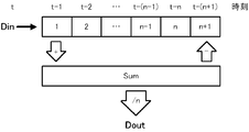
- FIG. 2 shows an outline of the calculation by the filtering unit 22.
- “Din” indicates an input value
- “Dout” indicates an output value.
- the input value Din is added to the first register in the list numbered from “1” to “n + 1”.
- This list corresponds to a first-in first-out queue, and the input value Din obtained immediately before the latest input value Din moves to the second register, and the input values Din are stored in the third and subsequent registers in the newest order. Will be done. Therefore, at time t, the first register stores the input value Din obtained at time t ⁇ 1, and the nth register stores the input value Din obtained at time t ⁇ n. .
- the time here corresponds to the sampling order. In an initial state before an input value is obtained, zero is stored in each register. n is the number of data of the input value to be subjected to the moving average.
- the subscript i in the above equation (1) indicates the number of the acquired input value, and the larger the value of i, the newer the input value of Dini.
- Din i means a current input value
- Din i-1 means an input value obtained immediately before Din i
- Dout i means a current output value
- Dout i-1 means an output value calculated immediately before Dout i .
- the above equation (1) can be modified as the following equation (2).
- the “Sum” register in FIG. 2 holds the sum of the values stored in the first to n-th registers. In this register, zero is initially stored.
- the filtering unit 22 adds the acquired input value Din to the first register, adds this value added to the first register to the value of the “Sum” register, The value of the sum is updated by subtracting the value moved from the n-th register to the (n + 1) -th register from the value of the “Sum” register. Then, the filtering unit 22 obtains the output value Dout by dividing the value of the “Sum” register by n.
- FIG. 3 shows an example of the calculation by the filtering unit 22.
- the value “8” is stored in the first register, and the value “1” is stored in the n-th register.
- the “Sum” register stores the sum “52” of the values stored in the first to n-th registers.
- this input value is added to the first register as shown in the lower part of FIG. From (n + 1) th to (n + 1) th.
- a value “60” is calculated. If the number of data n is 10, “6. An output value of “0” is calculated.
- the output unit 23 outputs the output value output from the filtering unit 22 according to the control of the system control unit 16.
- the output destination is, for example, a display terminal (not shown), a storage device, a signal processing circuit that performs signal processing on an output value of the filtering device 20, or a PLC (Programmable @ Logic) connected to the sensor device 10 via a sensor network. Controller) and other control devices.
- the filtering device 20 includes a processor 41, a main storage unit 42, an auxiliary storage unit 43, an input unit 44, an output unit 45, and a communication unit 46.
- the main storage unit 42, the auxiliary storage unit 43, the input unit 44, the output unit 45, and the communication unit 46 are all connected to the processor 41 via the internal bus 47.
- the processor 41 includes an MPU (Micro Processing Unit), a CPU (Central Processing Unit), or an FPGA (Field Programmable Gate Array).
- the processor 41 realizes various functions of the filtering device 20 by executing the program P1 stored in the auxiliary storage unit 43, and executes processing described below.
- the main storage unit 42 includes a RAM (Random Access Memory).
- the main storage unit 42 is loaded with the program P1 from the auxiliary storage unit 43.
- the main storage unit 42 is used as a work area of the processor 41.
- the auxiliary storage unit 43 includes a nonvolatile memory represented by an electrically erasable programmable read-only memory (EEPROM) and a hard disk drive (HDD).
- EEPROM electrically erasable programmable read-only memory
- HDD hard disk drive
- the auxiliary storage unit 43 stores various data used for the processing of the processor 41, in addition to the program P1.
- the auxiliary storage unit 43 supplies data used by the processor 41 to the processor 41 in accordance with an instruction from the processor 41, and stores the data supplied from the processor 41.
- the input unit 44 includes a terminal for inputting information from outside the filtering device 20.
- the input unit 44 acquires information input from the outside, and notifies the processor 41 of the acquired information.
- the output unit 45 includes a terminal for outputting information to the outside of the filtering device 20.
- the output unit 45 outputs information provided from the processor 41 to the outside according to an instruction from the processor 41.
- the communication unit 46 includes a network interface circuit for communicating with an external device.
- the communication unit 46 receives a signal from the outside and outputs data indicated by the signal to the processor 41.
- the communication unit 46 transmits a signal indicating data output from the processor 41 to an external device.
- FIG. 1 The various functions shown in FIG. 1 are realized by cooperation of the hardware configuration shown in FIG. Specifically, the input unit 44 mainly implements the acquisition unit 21. Mainly, the processor 41 and the main storage unit 42 implement the filtering unit 22. The output unit 45 mainly implements the output unit 23. However, the communication unit 46 may implement the output unit 23 when notifying the external device of the result of the filtering by communication.
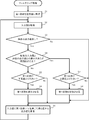
- the filtering process illustrated in FIG. 5 starts when the power of the filtering device 20 is turned on.
- the filtering device 20 sets the first coefficient (1 / n) to an initial value as an initialization process (Step S1). Specifically, the filtering unit 22 substitutes 1 as an initial value for a first coefficient which is the reciprocal of the number n of data to be subjected to the moving average. Thereby, the initial value of the data number n is set to 1.
- the first coefficient (1 / n) means a weight coefficient by which the current input value is multiplied.
- each of the plurality of input values is divided by the number of data n, and this division is equivalent to multiplying each of the plurality of input values by a coefficient (1 / n).
- the coefficient (1 / n) corresponds to the weight of each input value, and is a value in the range from zero to one.
- the filtering device 20 acquires an input value (step S2). Specifically, the acquisition unit 21 acquires the measurement value output from the measurement unit 14. Step S2 corresponds to a claim obtaining step.
- the filtering device 20 determines whether there is a past output value (step S3). Specifically, the filtering unit 22 determines whether or not there is an output value calculated earlier than the output value calculated from the input value acquired in step S2.
- the past output value usually means the previous output value.
- Step S3 If it is determined that there is no past output value (Step S3; No), the processing by the filtering device 20 proceeds to Step S9. On the other hand, when it is determined that there is a past output value (Step S3; Yes), the filtering device 20 determines whether or not the magnitude of the difference between the current input value and the past output value exceeds a threshold (Step S3). Step S4). Specifically, the filtering unit 22 calculates the absolute value of the difference between the current input value acquired in step S2 and the past output value determined to be present in step S3, and this absolute value is It is determined whether or not a predetermined threshold is exceeded.
- the threshold value may be a value stored in advance by the filtering device 20 or a value changed by the user.
- the filtering device 20 determines whether the first coefficient is larger than the lower limit (Step S5). Specifically, the filtering unit 22 determines whether the current first coefficient (1 / n) is greater than a predetermined lower limit.
- the lower limit value may be a value stored in advance by the filtering device 20 or a value changed by the user. This lower limit value corresponds to the reciprocal of the maximum value of the number of data to be subjected to the moving average. This lower limit is, for example, 1/64, 1/16384, or 1/131072.
- the determination in step S5 is normally affirmed.
- Step S5 If it is determined that the first coefficient is not larger than the lower limit (Step S5; No), the filtering device 20 proceeds to Step S9 without changing the first coefficient.
- the filtering device 20 decreases the first coefficient (Step S6). Specifically, the filtering unit 22 changes n of the first coefficient (1 / n) to a number larger by one. In other words, the filtering unit 22 increases the number n of data to be subjected to the moving average by one. Immediately after the activation of the filtering device 20, the number n of data is changed from 1 to 2, and the first coefficient is reduced from 1 to 1 /. Thereafter, the processing by the filtering device 20 proceeds to step S9.
- step S7 determines whether the first coefficient is smaller than the upper limit. Specifically, the filtering unit 22 determines whether the current first coefficient (1 / n) is smaller than a predetermined upper limit.
- the upper limit value may be a value stored in advance by the filtering device 20 or a value changed by a user. This upper limit corresponds to the reciprocal of the minimum value of the number n of data to be subjected to the moving average.
- the upper limit value is 1, but is not limited thereto, and may be, for example, 1/8 or 1/64.
- step S7 If it is determined that the first coefficient is not smaller than the upper limit (step S7; No), the filtering device 20 proceeds to step S9 without changing the first coefficient.
- the filtering device 20 increases the first coefficient (Step S8). Specifically, the filtering unit 22 changes the first coefficient (1 / n) to 1 by setting the number of data n to 1. As a result, the number n of data to be subjected to the moving average becomes only one for the input value to be acquired next.
- the filtering device 20 calculates an output value from a value obtained by multiplying the input value obtained in step S2 by the first coefficient (1 / n) (step S9). Specifically, the filtering unit 22 multiplies the current input value by a first coefficient (1 / n) and the second coefficient (1 / n) for each of the past (n-1) input values. ) Is calculated as the sum of the value obtained by multiplying the output value and the output value.
- the second coefficient has a value equal to the first coefficient.
- the second coefficient means a weight coefficient by which a past input value is multiplied.
- Step S9 corresponds to a filtering step in the claims.
- the filtering device 20 has not yet acquired the past input values immediately after the activation, but since the number of data n was set to 1 in step S1, the input values acquired in step S2 are used as output values as they are. I do.
- step S2 the filtering device 20 repeats the processing from step S2.
- an output value with reduced noise is calculated while changing the first coefficient with respect to the input value repeatedly acquired.
- FIG. 6 schematically shows a change in the number n of data to be subjected to the moving average.
- the upper part of FIG. 6 shows a case where the data number n is equal to 10.
- the number n of data is changed to 11, and the calculation is executed as shown in the middle part of FIG.
- the subtraction from the register value of “Sum” is omitted, and only the addition of a new input value is executed.
- the number n of data is decreased and the first coefficient is increased, the number n of data is changed to 1 and the operation is performed as shown in the lower part of FIG. However, immediately after the data number n is reduced, the new input value is stored in the “Sum” register as it is.
- the filtering device 20 when the difference between the current input value and the past output value exceeds the threshold value, the filtering device 20 outputs the current input value with a weight larger than the weight for obtaining the past output value. To obtain a new output value.
- the filtering device 20 calculates an output value from a value obtained by multiplying a current input value by a first coefficient (1 / n).
- the first coefficient corresponds to the degree of emphasis on the current input value. The larger the first coefficient is, the smaller the contribution of other data is, and the shorter the delay is, while the smaller the first coefficient is, the more the other data is. This will further reduce noise.
- the filtering device 20 increases the first coefficient to reduce the delay, and when the difference is small, reduces the first coefficient. To reduce noise. Thereby, the performance of filtering for reducing noise can be improved in accordance with the situation. As a result, it contributes to the improvement of the productivity of the production equipment using the filtering device 20 and the improvement of the quality of products.
- FIG. 7 schematically shows the transition of the input value and the output value, the magnitude of the difference between the input value and the previous output value, and the first coefficient.
- a broken line L11 in the upper part of FIG. 7 indicates a transition of a value separated by a threshold from the previous output value, and if the input value is out of the range surrounded by the two broken lines L11, the determination in step S4 in FIG. Will be affirmed.
- the magnitude of the difference between the previous output value and the input value is equal to or smaller than the threshold value, and the first coefficient has converged to the lower limit value.
- the number of data n is changed to 1 and the first coefficient increases to 1, and the newly calculated output value becomes the input value. Be equal.
- the number of data n increases to 2 and the first coefficient decreases to ⁇ , and a plurality of input values are again subjected to the moving average.
- the output value can follow this change with a small delay.
- the filtering device 20 calculates the output value by the moving average, and increases or decreases the number of data of the past input value to be the moving average according to the magnitude of the difference between the past output value and the current input value. I let it. Since the moving average is relatively easy to implement and is an effective method for reducing noise, the filtering device 20 can easily improve the performance of reducing noise.
- the filtering device 20 sets the initial value of the first coefficient (1 / n) to 1.
- the input value of the number n of data to be subjected to the moving average has not yet been input immediately after the start of the filtering, so that the output value does not become an appropriate value, and special processing immediately after the start is performed. Required.
- the initial value of the number of data n is set to 1 and the output value becomes equal to the input value, so that an appropriate output value can be easily obtained.
- the first coefficient (1 / n) is a value in the range from zero to 1, and the filtering device 20 determines that the difference between the past output value and the current input value exceeds the threshold value. , The first coefficient was set to 1. Accordingly, when the difference between the past output value and the current input value increases, the newly calculated output value becomes equal to the input value, and the output value can follow the input value with a small delay.
- the filtering process performed by the filtering device 20 is not limited to the above-described process.
- step S6 in FIG. 5 it has been described that the number n of data is increased by 1 to decrease the first coefficient.
- the decrease width of the first coefficient is not limited to this, and the number n of data is set to 2
- the first coefficient may be decreased by increasing by a factor of two. If the number of data n is doubled, the number of data n becomes a power of 2 and the calculation becomes easy.
- FIG. 8 shows a simulation result of an input value and an output value when the inventors increase the number of data n twice. In this simulation, a value in which noise is superimposed on the amount of displacement that changes stepwise is used as the input value. “In” in FIG. 8 indicates an input value, and “Out” indicates an output value. As shown in FIG. 8, the output value changes in a step-like manner, and it can be seen that the noise is reduced by the filtering process, and the output value follows a change different from the noise included in the input value with a small delay. .
- FIG. 9 shows the result of the moving average when the number of data n is fixed to 64 without changing the first coefficient under the same conditions as in the simulation of FIG.
- the output value reduces the noise to about 1/8, but it can be seen that a delay corresponding to 64 samplings has occurred with respect to the input value.
- step S3 the filtering device 10 determines whether or not the magnitude of the difference between the output value and the input value continuously exceeds the first threshold (step S11). Specifically, the filtering unit 22 determines whether the magnitude of the difference continuously exceeds the first threshold for a predetermined number of times or more. At this time, the value of the output exceeding the threshold value may be stored, and thereafter, the determination may be sequentially performed based on the difference between the input and the stored output.
- the output value when the difference from the input value exceeds the first threshold value is stored as a reference value, and for the next and subsequent input values, the error between the input value and the reference value is a predetermined error. May be determined continuously.
- the predetermined number of times is, for example, three, ten, or 100 times, and may be the number of times that the filtering device 20 stores in advance, or may be changed by the user.
- the first threshold value is a threshold value for determining whether to increase the first coefficient, and may be a value stored in advance by the filtering device 20 or may be changed by the user.
- Step S11 If it is determined that the magnitude of the difference continuously exceeds the first threshold (Step S11; Yes), the filtering device 20 proceeds to Step S7. On the other hand, when it is determined that the magnitude of the difference does not continuously exceed the first threshold (Step S11; No), the filtering device 20 determines that the magnitude of the difference between the output value and the input value is It is determined whether the value is below two thresholds (step S12). Specifically, the filtering unit 22 determines whether or not the magnitude of the difference is continuously lower than the second threshold for a predetermined number of times or more. This number may be the same as or different from the number used for the determination in step S11.
- the number of times is, for example, 3, 10, or 100 times, and may be the number of times that the filtering device 20 stores in advance, or may be changed by the user.
- the second threshold is different from the first threshold, and is a threshold for determining whether to decrease the first coefficient.
- the second threshold value may be a value stored in the filtering device 20 in advance, or may be changed by the user. Normally, a value larger than the first threshold is set as the second threshold.
- Step S12 If it is determined that the magnitude of the difference is continuously below the second threshold (Step S12; Yes), the filtering device 20 proceeds to Step S5. On the other hand, when it is determined that the magnitude of the difference does not continuously fall below the second threshold (step S12; No), the processing by the filtering device 20 proceeds to step S9. As a result, an output value with reduced noise is calculated while changing the first coefficient with respect to the input value repeatedly acquired.
- the first threshold for decreasing the first coefficient and the second threshold for increasing the first coefficient are set as different values. If the magnitude of the difference between the output value and the input value is larger than the first threshold and smaller than the second threshold, the first coefficient is not changed. For this reason, if the magnitude of the difference between the output value and the input value is stable within a certain range, the first coefficient is fixed, and high-speed arithmetic processing can be easily realized.
- the example shown in FIG. 5 can be said to be the case where the first threshold value and the second threshold value are equal.
- the first coefficient is changed when the magnitude of the difference between the output value and the input value continuously exceeds the first threshold value and when the magnitude of the difference continuously falls below the second threshold value. This prevents the first coefficient from being changed each time the input value greatly fluctuates due to temporary noise. As a result, arithmetic processing can be executed stably.
- each of the first coefficient and the one or more second coefficients is preferably a positive value, and is preferably in a range from zero to one. Further, the sum of the first coefficient and one or more second coefficients is desirably 1. Each of the plurality of second coefficients may have a different value.
- Embodiment 2 FIG. Next, the second embodiment will be described focusing on differences from the first embodiment.
- the filtering based on the moving average is applied to the input value.
- an IIR filter may be applied.
- an example in which an IIR filter is applied to an input value will be described.
- FIG. 11 shows an outline of the calculation by the filtering unit 22 according to the present embodiment.
- “Reg” in the block diagram of FIG. 11 indicates an operation of registering in a register.
- a value obtained by multiplying a current input value Din i by a first coefficient (1 / n) and a value obtained by multiplying a past output value Dout i-1 by a third coefficient ((n-1) / n) Is output as a new output value Dout i .
- This calculation is represented by the following equation (3).
- the third coefficient is a weight coefficient for multiplying a past output value.
- the current output value is calculated by inner product of the previous output value and the current input value.
- a new output value is calculated as a weighted average of the current input value and the past output value.
- the output value corresponds to a weighted average of past input values.
- the current input value is multiplied by the first coefficient (1 / n). Therefore, by increasing the first coefficient (1 / n), it is possible to obtain an output value that follows the current input value by reducing the delay, and to decrease the first coefficient (1 / n). Noise can be further reduced by a weighted average of past input values.
- the operation by the filtering unit 22 may be realized by a block diagram as shown in FIG.
- the calculation of the output value shown in the example of FIG. 12 is represented by the following expression (4) obtained by modifying the above expression (3).
- the filtering device 20 calculates the current output value as a weighted average of the current input value and the past output value. Thereby, the filtering device 20 can perform the same processing as in FIG. 5 and achieve the same effect as in the first embodiment.
- FIG. 13 shows the result of comparison between the IIR filter and the moving average when the number of data n is doubled by the inventors.
- a point P21 indicated by “+” indicates an input value
- a diamond-shaped point P22 indicates a standard deviation of the input value
- a large circle-shaped point P23 indicates an output value by the moving average
- a round point P24 indicates an output value by the IIR filter.
- the line L21 indicates the theoretical noise reduction rate 1 / ⁇ n
- the large diamond-shaped point P25 indicates the noise reduction rate by the moving average
- the small diamond-shaped point P26 indicates the noise reduction rate by the IIR filter.
- the IIR filter can reduce the noise substantially along the theoretical reduction rate.
- the moving average and the noise reduction rate by the IIR filter are calculated as (standard deviation of output value) / (standard deviation of input value).
- the operation can be performed only by preparing one register.
- the filtering process can be executed with less hardware resources than the moving average that requires a plurality of registers as shown in FIG.
- a new output value may be calculated using a plurality of past output values.
- the first coefficient by which the current input value is multiplied is (1 / n) and the third coefficient by which the past output value is multiplied is ((n-1) / n).
- Each of the third coefficients may have a value different from that described above. However, it is desirable that each of the first coefficient and the one or more third coefficients be a positive value and be within a range from zero to one. Further, the sum of the first coefficient and one or more third coefficients is desirably 1. Each of the plurality of third coefficients may have a different value.
- Embodiment 3 FIG. Next, a third embodiment will be described focusing on differences from the first embodiment.
- the threshold is a parameter that is defined in advance. However, it is desirable that the threshold be determined according to the magnitude of noise. Therefore, an example in which a threshold is determined according to the magnitude of noise will be described below.
- the filtering device 20 executes the filtering process shown in FIG.
- the filtering device 20 sets a threshold based on the standard deviation of past input values (step S31).
- the filtering unit 22 calculates the standard deviation of P input values defined in advance, and sets a value of Q times the calculated standard deviation as a threshold.
- the values of P and Q may be values stored in the filtering device 20 in advance, or may be changed by the user.
- P is desirably a large number of times to obtain a valid standard deviation, for example, 32, 64, or 128.
- Q is determined according to the magnitude of the noise and the displacement amount of the measurement target. For example, if the amount of displacement changes stepwise and the amount of change is significantly larger than the noise, an output value that follows the displacement with a small delay while reducing noise by setting P to a relatively large value. Can be obtained.
- P may be, for example, 3 or 4.
- the filtering device 20 calculates the threshold from the standard deviation of the input value, and changes the first coefficient based on the threshold. As a result, even in the case where the magnitude of the noise fluctuates over time, the first coefficient can be changed using an appropriate threshold value according to the magnitude of the noise to perform appropriate filtering.
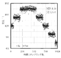
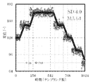
- FIG. 15 shows a simulation of the input value, the output value, and the standard deviation in the case where the inventors have specified the threshold according to the standard deviation of the past input values.
- “SD” in FIG. 15 indicates a standard deviation.
- a value obtained by superimposing noise on the amount of displacement that changes stepwise was used as an input value.
- the output value can follow the displacement amount that changes stepwise with a small delay. Further, the output value changes in a step-like manner, and noise can be reduced.
- the first threshold and the second threshold in the modification of FIG. 10 may be defined according to the standard deviation.
- the threshold value can be defined according to the standard deviation.
- the threshold value may be defined according to the statistical value of at least one of the past input value and output value, without being limited to the standard deviation.
- a statistic one or more of a variation in a difference between an output value and an input value, a peak value or a peak position in a histogram of the difference, a deviation of the difference, and a time variation of a statistic related to the histogram are described. It is conceivable to define the threshold value according to.
- the senor device 10 is a laser displacement device.
- the present invention is not limited to this, and the sensor device 10 may be another sensing device.
- the input unit 44 and the output unit 45 may form a user interface that exchanges information with a user.
- the change amount when changing the first coefficient is not limited to the above example, and may be arbitrarily set by the user.
- the initial value of the first coefficient is not limited to the above example, and may be arbitrarily set by the user.
- the present invention is not limited to this.
- the sensor device 10 and the filtering device 20 may be configured as different devices. It is also conceivable that the sensor device 10 and the filtering device 20 are integrally configured.
- the processor 41 may realize the measuring unit 14, and the acquiring unit 21 and the measuring unit 14 may be integrally formed.
- the filtering device 20 may calculate an output value according to the following equation (5).
- the number K of past input values used for calculation and the number M of past output values used for calculation may be set arbitrarily.
- the filtering device 20 when the filtering device 20 changes the first coefficient according to the current input value, the filtering device 20 calculates a new output value from the current input value using the changed first coefficient, but is not limited thereto.
- the first coefficient whose value has been changed may be applied to input values for the next and subsequent times.
- the function of the filtering device 20 can be realized by dedicated hardware or a normal computer system.
- the program P1 executed by the processor 41 is stored in a non-transitory computer-readable recording medium and distributed, and the program P1 is installed in a computer to configure an apparatus that executes the above-described processing. be able to.
- a recording medium include a flexible disk, a CD-ROM (Compact Disc-Only Memory), a DVD (Digital Versatile Disc), and an MO (Magneto-Optical Disc).
- the program P1 may be stored in a disk device of a server device on a communication network represented by the Internet, and may be superimposed on a carrier wave and downloaded to a computer, for example.
- the above-described processing can also be achieved by starting and executing the program P1 while transferring the program P1 via the communication network.
- the above-described processing can also be achieved by causing all or a part of the program P1 to be executed on a server device and executing the program while the computer transmits and receives information regarding the processing via a communication network.
- the means for realizing the function of the filtering device 20 is not limited to software, and a part or all of the means may be realized by dedicated hardware including a circuit.
- the present invention is suitable for filtering for reducing noise.
Landscapes
- Physics & Mathematics (AREA)
- General Physics & Mathematics (AREA)
- Image Processing (AREA)
- Length Measuring Devices By Optical Means (AREA)
- Length Measuring Devices With Unspecified Measuring Means (AREA)
- Indication And Recording Devices For Special Purposes And Tariff Metering Devices (AREA)
- Measurement And Recording Of Electrical Phenomena And Electrical Characteristics Of The Living Body (AREA)
Abstract
フィルタリング装置(20)は、取得部(21)と、フィルタリング部(22)と、を備える。取得部(21)は、繰り返し入力される入力値を取得する。フィルタリング部(22)は、入力値に含まれるノイズを低減するフィルタリングにより出力値を得る。また、フィルタリング部(22)は、現在の入力値と過去の出力値との差が第1閾値を超える場合に、該過去の出力値を得るための重みよりも大きい重みで現在の入力値の重み付けをすることで新たな出力値を得る。
Description
本発明は、フィルタリング装置、センサ装置、フィルタリング方法及びプログラムに関する。
工場に代表される施設では、センサによる測定値を利用して生産システム、加工システム、検査システムを含む種々のシステムが運用される。センサによる測定値は、通常、ノイズを含んでいるため、この測定値をフィルタに通してノイズを低減することが広く行われている。ノイズを低減するフィルタとしては、複数の測定値の平均をとる移動平均及びIIR(Infinite Impulse Response)フィルタが知られている。ここで、測定値の平均をとることには、単純な算術平均の他、加重平均に代表される種々の演算が含まれる。
例えば、n個の測定値の移動平均によれば、ノイズを1/√n程度に低減することが見込まれる。このため、移動平均の対象となるデータ数nを多くすればノイズの低減率を高くすることができる。ただし、データ数nが多くなると、測定値がノイズとは異なる変化を含むときに移動平均の値がその変化に大きく遅延して追随することとなってしまう。そこで、移動平均に用いるデータ数を、ユーザが設定した精度及び応答時間に応じて設定する技術が提案されている(例えば、特許文献1を参照)。
特許文献1の技術は、データ数を一旦設定すると、繰り返し入力される計測データに対してこの設定を変更することなく移動平均の演算をする。このため、ユーザが精度を重視した設定とすると遅延が大きくなってしまい、一方、ユーザが応答時間を重視した設定とすると精度が低下してしまう。したがって、ノイズを低減するためのフィルタリングの性能をある程度確保しつつ、応答性を向上させる余地があった。
本発明は、上記の事情に鑑みてなされたものであり、ノイズを低減するためのフィルタリングの性能をある程度確保しつつ、応答性を向上させることを目的とする。
上記目的を達成するため、本発明のフィルタリング装置は、繰り返し入力される入力値を取得する取得手段と、入力値に含まれるノイズを低減するフィルタリングにより出力値を得るフィルタリング手段と、を備え、フィルタリング手段は、現在の入力値と過去の出力値との差が第1閾値を超える場合に、該過去の出力値を得るための重みよりも大きい重みで現在の入力値の重み付けをすることで新たな出力値を得る。
本発明によれば、フィルタリング手段は、現在の入力値と過去の出力値との差が第1閾値を超える場合に、該過去の出力値を得るための重みよりも大きい重みで現在の入力値の重み付けをすることで新たな出力値を得る。現在の入力値の重みが大きいほど過去のデータによる寄与が少なくなり遅延を縮小することができる。これにより、ノイズを低減するためのフィルタリングの性能をある程度確保しつつ、応答性を向上させることができる。
以下、本発明の実施の形態に係るフィルタリングを実行するセンサ装置10について、図面を参照しつつ詳細に説明する。
実施の形態1.
本実施の形態に係るセンサ装置10は、レーザ光を利用して対象物までの距離の変化量を計測するレーザ変位センサである。センサ装置10は、図1に示されるように、ワーク30に向けてレーザ光を照射する発光素子11と、ワーク30において反射した反射光を結像するためのレンズ12と、レンズ12を透過した反射光を受光する受光素子13と、受光素子13の出力から計測値としてのワーク30の変位量を算出する計測部14と、発光素子11及び受光素子13を制御する素子制御部15と、計測部14、素子制御部15及びフィルタリング装置20を含むレーザ変位センサシステムを制御するシステム制御部16と、計測部14から出力される計測値に含まれるノイズを低減するフィルタリング装置20と、を有する。
本実施の形態に係るセンサ装置10は、レーザ光を利用して対象物までの距離の変化量を計測するレーザ変位センサである。センサ装置10は、図1に示されるように、ワーク30に向けてレーザ光を照射する発光素子11と、ワーク30において反射した反射光を結像するためのレンズ12と、レンズ12を透過した反射光を受光する受光素子13と、受光素子13の出力から計測値としてのワーク30の変位量を算出する計測部14と、発光素子11及び受光素子13を制御する素子制御部15と、計測部14、素子制御部15及びフィルタリング装置20を含むレーザ変位センサシステムを制御するシステム制御部16と、計測部14から出力される計測値に含まれるノイズを低減するフィルタリング装置20と、を有する。
発光素子11は、レーザ素子としてのレーザダイオードを含む。受光素子13は、配列された複数の光電変換素子を含む撮像素子である。複数の光電変換素子はそれぞれ、受光強度に応じた電圧値を出力する。受光素子13は、受光強度の分布を示す情報を計測部14に出力する。
計測部14は、受光強度の分布からピークを検出して、当該ピークの受光位置から三角測距によりワーク30との変位量を算出する。計測部14は、算出した変位量を計測値としてフィルタリング装置20に出力する。計測部14は、請求項の計測手段として機能する。
素子制御部15は、発光素子11の発光及び受光素子13の受光を制御する。詳細には、素子制御部15は、発光素子11による発光の強度及び時間を制御し、受光素子13による撮像のタイミングを制御する。
システム制御部16は、素子制御部15を制御することにより発光素子11の発光及び受光素子13の受光を繰り返し実行させて、計測部14に計測値を繰り返し算出させる。また、システム制御部16は、フィルタリング装置20を制御して、例えば、フィルタリングに関するパラメータの設定、及びフィルタリング結果の出力先に関する設定をする。
フィルタリング装置20は、計測値にフィルタリングを施して、計測値に含まれるノイズを低減しつつ、計測値に対するある程度高い追従性を有する出力値を算出する装置である。フィルタリング装置20は、フィルタを構成する係数を適応的に変化させることで、計測値がノイズとは異なる変動を含むときに、出力値がこの変動に追従する際の遅延を縮小する。
フィルタリング装置20は、計測値を取得する取得部21と、計測値にフィルタリングを施すフィルタリング部22と、フィルタリングの結果を出力する出力部23と、を有する。
取得部21は、フィルタリング装置20に入力される入力値として、計測部14から繰り返し出力される計測値を取得する。計測値のサンプリング周期は、例えば100μs、1ms、又は10msである。取得部21は、入力値を取得するたびに、この入力値をフィルタリング部22に出力する。取得部21は、請求項の取得手段として機能する。
フィルタリング部22は、過去の一定期間に取得した複数の入力値から、ノイズが低減された出力値を移動平均により演算する。詳細には、フィルタリング部22は、現在時点における最新の入力値を含むn個の入力値の平均値を出力値として算出する。フィルタリング部22は、請求項のフィルタリング手段として機能する。
図2には、フィルタリング部22による演算の概要について示されている。図2において、「Din」は入力値を示し、「Dout」は出力値を示す。入力値Dinが新たに入力されると、この入力値Dinは、「1」から「n+1」までの番号が付されたリストのうち1番目のレジスタに追加される。このリストは、先入れ先出しのキューに相当し、最新の入力値Dinの直前に取得された入力値Dinは、2番目のレジスタに移動し、3番目以降のレジスタには、新しい順に入力値Dinが格納されることとなる。このため、時刻tにおいては、1番目のレジスタには時刻t-1に取得された入力値Dinが格納され、n番目のレジスタには時刻t-nに取得された入力値Dinが格納される。なお、ここでの時刻は、サンプリングした順番に対応する。また、入力値が取得される前の初期状態では、各レジスタにゼロが格納される。nは、移動平均の対象となる入力値のデータ数である。
ここで、データ数をnとする移動平均による出力値の算出は、以下の式(1)で表される。

ただし、上記式(1)中の添字iは、取得された入力値の番号を示し、iが大きいほどDiniは新しい入力値となる。上記式(1)では、Diniは、現在の入力値を意味し、Dini-1は、Diniの直前に取得された入力値を意味する。また、Doutiは、現在の出力値を意味し、Douti-1は、Doutiの直前に算出された出力値を意味する。上記式(1)は、以下の式(2)のように変形することができる。
Douti=(1/n)(n・Douti-1+Dini-Dini-n)
=Douti-1+(1/n)(Dini-Dini-n) ・・・(2)
Douti=(1/n)(n・Douti-1+Dini-Dini-n)
=Douti-1+(1/n)(Dini-Dini-n) ・・・(2)
上記式(2)は、前回の出力値Douti-1に対して、現在の入力値Diniを1/n倍した値を加算するとともに、n回前の入力値を(1/n)倍した値を減算することで、現在の出力値が算出されることを示している。この演算によれば、入力値を取得するたびにn個の入力値を格納するレジスタそれぞれにアクセスすることなく出力値が算出される。
図2中の「Sum」のレジスタは、1番目からn番目までのレジスタに格納された値の総和を保持する。このレジスタには、初期状態ではゼロが格納される。フィルタリング部22は、入力値Dinを取得するたびに、取得した入力値Dinを1番目のレジスタに追加し、1番目のレジスタに追加したこの値を「Sum」のレジスタの値に加算するとともに、n番目のレジスタから(n+1)番目のレジスタに移動した値を「Sum」のレジスタの値から減算することにより、総和の値を更新する。そして、フィルタリング部22は、「Sum」のレジスタの値をnで除算することにより、出力値Doutを得る。
図3には、フィルタリング部22による演算の一例が示されている。図3の上段では、1番目のレジスタに「8」という値が格納されていて、n番目のレジスタに「1」という値が格納されている。「Sum」のレジスタには、1番目からn番目までのレジスタに格納されている値の総和「52」が格納されている。この状態において新たな入力値「9」が入力されると、この入力値は、図3の下段に示されるように、1番目のレジスタに追加されて、「1」の値はn番目のレジスタからn+1番目に移動する。そして、「Sum」のレジスタの値「52」について「9」が加算されるとともに「1」が減算された結果「60」という値が算出され、データ数nが10であれば、「6.0」という出力値が算出される。
図1に戻り、出力部23は、フィルタリング部22から出力される出力値を、システム制御部16による制御に従って出力する。出力先は、例えば、不図示の表示端末、記憶装置、フィルタリング装置20の出力値に対して信号処理を施す信号処理回路、又は、センサネットワークを介してセンサ装置10に接続されるPLC(Programmable Logic Controller)その他の制御装置である。
続いて、フィルタリング装置20のハードウェア構成について、図4を参照しつつ説明する。フィルタリング装置20は、図4に示されるように、プロセッサ41と、主記憶部42と、補助記憶部43と、入力部44と、出力部45と、通信部46と、を有する。主記憶部42、補助記憶部43、入力部44、出力部45及び通信部46はいずれも、内部バス47を介してプロセッサ41に接続される。
プロセッサ41は、MPU(Micro Processing Unit)、CPU(Central Processing Unit)又は、FPGA(Field Programmable Gate Array)を含む。プロセッサ41は、補助記憶部43に記憶されるプログラムP1を実行することにより、フィルタリング装置20の種々の機能を実現して、後述の処理を実行する。
主記憶部42は、RAM(Random Access Memory)を含む。主記憶部42には、補助記憶部43からプログラムP1がロードされる。そして、主記憶部42は、プロセッサ41の作業領域として用いられる。
補助記憶部43は、EEPROM(Electrically Erasable Programmable Read-Only Memory)及びHDD(Hard Disk Drive)に代表される不揮発性メモリを含む。補助記憶部43は、プログラムP1の他に、プロセッサ41の処理に用いられる種々のデータを記憶する。補助記憶部43は、プロセッサ41の指示に従って、プロセッサ41によって利用されるデータをプロセッサ41に供給し、プロセッサ41から供給されたデータを記憶する。
入力部44は、フィルタリング装置20の外部から情報を入力するための端子を含む。入力部44は、外部から入力された情報を取得して、取得した情報をプロセッサ41に通知する。出力部45は、フィルタリング装置20の外部に情報を出力するための端子を含む。出力部45は、プロセッサ41の指示に従って、プロセッサ41から提供された情報を外部に出力する。
通信部46は、外部の装置と通信するためのネットワークインタフェース回路を含む。通信部46は、外部から信号を受信して、この信号により示されるデータをプロセッサ41へ出力する。また、通信部46は、プロセッサ41から出力されたデータを示す信号を外部の装置へ送信する。
図4に示されるハードウェア構成が協働することにより、図1に示される種々の機能が実現される。詳細には、主として入力部44が、取得部21を実現する。主としてプロセッサ41及び主記憶部42が、フィルタリング部22を実現する。主として出力部45が、出力部23を実現する。ただし、フィルタリングを施した結果を通信により外部の装置へ通知する際には、通信部46が出力部23を実現してもよい。
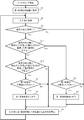
続いて、フィルタリング装置20によって実行されるフィルタリング処理について、図5を参照しつつ説明する。図5に示されるフィルタリング処理は、フィルタリング装置20の電源が投入されることで開始する。
フィルタリング処理では、フィルタリング装置20は、初期化処理として、第1係数(1/n)を初期値に設定する(ステップS1)。具体的には、フィルタリング部22が、移動平均の対象となるデータ数nの逆数である第1係数に対して、初期値として1を代入する。これにより、データ数nの初期値が1に設定される。
なお、第1係数(1/n)は、現在の入力値に乗じる重み係数を意味する。フィルタリング部22が移動平均を施す場合には、複数の入力値それぞれをデータ数nで除算することとなり、この除算は、複数の入力値それぞれに係数(1/n)を乗じることに等しい。また、係数(1/n)は、入力値それぞれの重みに相当し、ゼロから1までの範囲内の値である。
次に、フィルタリング装置20は、入力値を取得する(ステップS2)。具体的には、取得部21が、計測部14から出力される計測値を取得する。ステップS2は、請求項の取得ステップに対応する。
次に、フィルタリング装置20は、過去の出力値があるか否かを判定する(ステップS3)。具体的には、フィルタリング部22が、ステップS2で取得した入力値から算出される出力値よりも過去に算出された出力値があるか否かを判定する。ここで、過去の出力値は、通常、前回の出力値を意味する。
過去の出力値がないと判定した場合(ステップS3;No)、フィルタリング装置20による処理は、ステップS9へ移行する。一方、過去の出力値があると判定した場合(ステップS3;Yes)、フィルタリング装置20は、現在の入力値と過去の出力値との差の大きさが閾値を超えるか否かを判定する(ステップS4)。具体的には、フィルタリング部22が、ステップS2で取得した現在の入力値と、ステップS3で存在すると判定された過去の出力値と、の差の絶対値を算出して、この絶対値が、予め規定された閾値を超えるか否かを判定する。閾値は、フィルタリング装置20が予め記憶する値であってもよいし、ユーザによって変更された値であってもよい。
差の大きさが閾値を超えないと判定した場合(ステップS4;No)、フィルタリング装置20は、第1係数が下限値より大きいか否かを判定する(ステップS5)。具体的には、フィルタリング部22は、現在の第1係数(1/n)が予め規定された下限値より大きいか否かを判定する。下限値は、フィルタリング装置20が予め記憶する値であってもよいし、ユーザによって変更された値であってもよい。この下限値は、移動平均の対象となるデータ数の最大値の逆数に相当する。この下限値は、例えば、1/64、1/16384、又は1/131072である。フィルタリング装置20が起動した直後においては、係数の初期値が上限値である1に等しいため、ステップS5の判定は、通常、肯定される。
第1係数が下限値より大きくはないと判定した場合(ステップS5;No)、フィルタリング装置20は、第1係数を変更することなく、フィルタリング装置20による処理は、ステップS9へ移行する。
一方、第1係数が下限値より大きいと判定した場合(ステップS5;Yes)、フィルタリング装置20は、第1係数を減少させる(ステップS6)。具体的には、フィルタリング部22が、第1係数(1/n)のnを1だけ大きい数に変更する。換言すると、フィルタリング部22が、移動平均の対象となるデータ数nを1つ増やす。フィルタリング装置20が起動した直後は、データ数nが1から2に変更され、第1係数が1から1/2に減少することとなる。その後、フィルタリング装置20による処理は、ステップS9へ移行する。
ステップS4にて、差の大きさが閾値を超えると判定した場合(ステップS4;Yes)、フィルタリング装置20は、第1係数が上限値より小さいか否かを判定する(ステップS7)。具体的には、フィルタリング部22は、現在の第1係数(1/n)が予め規定された上限値より小さいか否かを判定する。上限値は、フィルタリング装置20が予め記憶する値であってもよいし、ユーザによって変更された値であってもよい。この上限値は、移動平均の対象となるデータ数nの最小値の逆数に相当する。この上限値は、1であるが、これには限定されず、例えば1/8又は1/64であってもよい。
第1係数が上限値より小さくはないと判定した場合(ステップS7;No)、フィルタリング装置20は、第1係数を変更することなく、フィルタリング装置20による処理は、ステップS9へ移行する。
一方、第1係数が上限値より小さいと判定した場合(ステップS7;Yes)、フィルタリング装置20は、第1係数を増加させる(ステップS8)。具体的には、フィルタリング部22が、データ数nを1に設定することにより第1係数(1/n)を1に変更する。これにより、次に取得される入力値に関して、移動平均の対象となるデータ数nが1つだけになる。
次に、フィルタリング装置20は、ステップS2で取得した入力値に第1係数(1/n)を乗じて得る値から出力値を算出する(ステップS9)。具体的には、フィルタリング部22が、現在の入力値に第1係数(1/n)を乗じて得る値と、過去の(n-1)個の入力値それぞれに第2係数(1/n)を乗じて得る値と、の総和として出力値を算出する。ここで、単純な移動平均の場合には、第2係数は、第1係数に等しい値になる。第2係数は、過去の入力値に乗じる重み係数を意味する。ステップS9は、請求項のフィルタリングステップに対応する。
なお、フィルタリング装置20は、起動した直後には過去の入力値を未だ取得していないが、ステップS1にてデータ数nを1に設定したため、ステップS2にて取得した入力値をそのまま出力値とする。
その後、フィルタリング装置20は、ステップS2以降の処理を繰り返す。これにより、繰り返し取得した入力値に対して、第1係数を変更しつつ、ノイズが低減された出力値を算出することとなる。
図6には、移動平均の対象となるデータ数nの変更について模式的に示されている。図6の上段には、データ数nが10に等しい場合が示されている。ここで、データ数nを増加させて第1係数を減少させると、データ数nが11に変更されて、図6の中段に示されるように演算が実行される。ただし、データ数nを増加させた直後には、「Sum」のレジスタ値からの減算が省略され、新たな入力値の加算のみが実行される。
また、データ数nを減少させて第1係数を増加させると、データ数nが1に変更されて、図6の下段に示されるように演算が実行される。ただし、データ数nを減少させた直後は、新たな入力値がそのまま「Sum」のレジスタに格納される。
以上、説明したように、フィルタリング装置20は、現在の入力値と過去の出力値との差が閾値を超える場合に、該過去の出力値を得るための重みよりも大きい重みで現在の入力値の重み付けをすることで新たな出力値を得る。現在の入力値の重みが大きいほど他のデータによる寄与が少なくなり遅延を縮小することができる。これにより、ノイズを低減するためのフィルタリングの性能をある程度確保しつつ、応答性を向上させることができる。
詳細には、フィルタリング装置20は、現在の入力値に第1係数(1/n)を乗じて得る値から出力値を算出する。この第1係数は、現在の入力値に重点を置く度合いに相当し、第1係数が大きいほど他のデータによる寄与が少なくなり遅延が縮小する一方、第1係数が小さいほど他のデータを多く使用してノイズをより低減することとなる。そして、フィルタリング装置20は、現在の入力値と過去の出力値との差が大きい場合には、第1係数を増加させて遅延を縮小し、この差が小さい場合には、第1係数を減少させてノイズを低減する。これにより、ノイズを低減するためのフィルタリングの性能を状況に応じて向上させることができる。ひいては、フィルタリング装置20を利用する生産設備の生産性向上、製品の品質向上に寄与する。
図7には、入力値及び出力値と、入力値と前回の出力値との差の大きさと、第1係数と、のそれぞれの推移が模式的に示されている。図7の上段のうち破線L11は、前回の出力値から閾値だけ離れた値の推移を示し、入力値が2本の破線L11で囲まれる範囲外にあると、図5中のステップS4の判定が肯定されることとなる。
図7に示されるように、時刻T1までは、前回の出力値と入力値との差の大きさが閾値以下であって、第1係数は、下限値に収束している。時刻T2においては、前回の出力値と入力値との差が閾値を超えたため、データ数nが1に変更され第1係数が1に増加して、新たに算出される出力値は入力値に等しくなる。そして、次の時刻T3では、データ数nが2に増加して第1係数が1/2に減少し、複数の入力値が再び移動平均の対象となっている。図7に示されるように、入力値がノイズとは異なる変化を含む場合においても、出力値は、この変化に対して少ない遅延で追従することができる。
また、フィルタリング装置20は、移動平均により出力値を算出し、過去の出力値と現在の入力値との差の大きさに応じて、移動平均の対象とする過去の入力値のデータ数を増減させた。移動平均は、比較的実装が容易であり、ノイズの低減に有効な手法であるため、フィルタリング装置20は、ノイズを低減する性能を容易に向上させることができる。
また、フィルタリング装置20は、第1係数(1/n)の初期値を1に設定した。一般的な移動平均では、フィルタリングの開始直後には移動平均の対象となるデータ数nの入力値が未だ入力されていないため、出力値が適当な値とならず、開始直後の特殊な処理が必要となる。これに対して、フィルタリング装置20によれば、データ数nの初期値が1に設定され、出力値が入力値と等しくなることから、簡便に適当な出力値を得ることができる。
また、第1係数(1/n)はゼロから1までの範囲内の値であって、フィルタリング装置20は、過去の出力値と現在の入力値との差の大きさが閾値を超える場合に、第1係数を1に設定した。これにより、過去の出力値と現在の入力値との差が大きくなると、新たに算出される出力値は入力値に等しくなり、出力値を少ない遅延で入力値に追従させることができる。
なお、フィルタリング装置20によるフィルタリング処理は、上述の処理に限定されない。
例えば、図5中のステップS6にて、データ数nを1だけ増加させて第1係数を減少させることを説明したが、第1係数の減少幅はこれに限定されず、データ数nを2倍に増加させて第1係数を減少させてもよい。データ数nを2倍に増加させれば、データ数nは2の乗数となり、演算が容易になる。図8には、発明者らが、データ数nを2倍に増加させた場合における入力値と出力値とのシミュレーション結果が示されている。このシミュレーションでは、ステップ状に変化する変位量にノイズが重畳した値が入力値とされている。図8中の「In」は入力値を示し、「Out」は出力値を示す。図8に示されるように、出力値がステップ状に推移しており、フィルタリング処理によってノイズを低減しつつ、入力値に含まれるノイズとは異なる変化にも少ない遅延で追従していることがわかる。
ここで、図8のシミュレーションと同等の条件で、第1係数を変更することなくデータ数nを64に固定した場合の移動平均の結果が、図9に示されている。図9の例では、出力値がノイズを1/8程度に低減しているが、入力値に対して64回のサンプリングに相当する遅延が発生していることがわかる。
また、図5のフィルタリング処理を、図10の変形例のように変更してもよい。図10のフィルタリング処理では、ステップS3に続いて、フィルタリング装置10は、出力値と入力値との差の大きさが連続して第1閾値を超えるか否かを判定する(ステップS11)。具体的には、フィルタリング部22が、この差の大きさが予め規定された回数以上連続して第1閾値を超えるか否かを判定する。この時、閾値を超えた出力の値を記憶し、その後、入力と記憶された出力との差分で逐次判断してもよい。具体的には、入力値との差が第1閾値を超えたときの出力値を基準値として記憶し、次回以降の入力値に関しては、入力値と基準値との誤差が予め規定された誤差の範囲内に連続して収まるか否かを判断してもよい。予め規定された回数は、例えば3回、10回又は100回であって、フィルタリング装置20が予め記憶する回数であってもよいし、ユーザによって変更されてもよい。また、第1閾値は、第1係数を増加させるか否かを判定するための閾値であって、フィルタリング装置20が予め記憶する値であってもよいし、ユーザによって変更されてもよい。
差の大きさが連続して第1閾値を超えると判定した場合(ステップS11;Yes)、フィルタリング装置20は、処理をステップS7へ移行する。一方、差の大きさが連続して第1閾値を超えてはいないと判定した場合(ステップS11;No)、フィルタリング装置20は、出力値と入力値との差の大きさが連続して第2閾値を下回るか否かを判定する(ステップS12)。具体的には、フィルタリング部22が、この差の大きさが、予め規定された回数以上連続して第2閾値を下回るか否かを判定する。この回数は、ステップS11の判定に用いられる回数と同一であってもよいし異なっていてもよい。また、この回数は、例えば3回、10回又は100回であって、フィルタリング装置20が予め記憶する回数であってもよいし、ユーザによって変更されてもよい。また、第2閾値は、第1閾値とは異なる値であって、第1係数を減少させるか否かを判定するための閾値である。第2閾値は、フィルタリング装置20が予め記憶する値であってもよいし、ユーザによって変更されてもよい。通常は、第2閾値としては、第1閾値より大きい値が設定される。
差の大きさが連続して第2閾値を下回ると判定した場合(ステップS12;Yes)、フィルタリング装置20は、処理をステップS5へ移行する。一方、差の大きさが連続して第2閾値を下回ってはいないと判定した場合(ステップS12;No)、フィルタリング装置20による処理は、ステップS9へ移行する。これにより、繰り返し取得した入力値に対して、第1係数を変更しつつ、ノイズが低減された出力値を算出することとなる。
図10の変形例では、第1係数を減少させるための第1閾値と、第1係数を増加させるための第2閾値とは、異なる値として設定された。出力値と入力値との差の大きさが第1閾値より大きく第2閾値より小さければ、第1係数が変更されることがない。このため、出力値と入力値との差の大きさがある程度の範囲内で安定していれば、第1係数が固定され、演算処理の高速化を容易に実現することができる。なお、図5に示される例は、第1閾値と第2閾値が等しい場合といえる。
また、図10の変形例では、出力値と入力値との差の大きさが連続して第1閾値を超える場合及び連続して第2閾値を下回る場合に、第1係数が変更された。これにより、一時的なノイズにより入力値が大きく変動する度に第1係数が変更されることが回避される。ひいては、演算処理を安定して実行することができる。
また、現在の入力値に乗じる第1係数と、過去の入力値に乗じる第2係数と、が等しい例を説明したが、第1係数及び第2係数はそれぞれ、上記説明と異なる値であってもよい。ただし、第1係数と一又は複数の第2係数はそれぞれ、正値であって、ゼロから1までの範囲内にあることが望ましい。さらに、第1係数と一又は複数の第2係数との総和は、1であることが望ましい。複数の第2係数はそれぞれ、異なる値であってもよい。
実施の形態2.
続いて、実施の形態2について、上述の実施の形態1との相違点を中心に説明する。なお、上記実施の形態と同一又は同等の構成については、同等の符号を用いるとともに、その説明を省略又は簡略する。上記実施の形態1では、移動平均によるフィルタリングを入力値に対して施したが、IIRフィルタを施す形態も考えられる。以下、入力値にIIRフィルタを適用する例について説明する。
続いて、実施の形態2について、上述の実施の形態1との相違点を中心に説明する。なお、上記実施の形態と同一又は同等の構成については、同等の符号を用いるとともに、その説明を省略又は簡略する。上記実施の形態1では、移動平均によるフィルタリングを入力値に対して施したが、IIRフィルタを施す形態も考えられる。以下、入力値にIIRフィルタを適用する例について説明する。
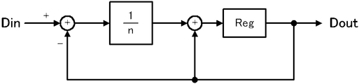
図11には、本実施の形態に係るフィルタリング部22による演算の概要が示されている。図11のブロック線図において「Reg」は、レジスタに登録する操作を示す。この演算では、現在の入力値Diniに第1係数(1/n)を乗じた値と、過去の出力値Douti-1に第3係数((n-1)/n)を乗じた値と、の総和が新たな出力値Doutiとして出力される。この演算は、以下の式(3)で示される。第3係数は、過去の出力値に乗じる重み係数である。
Douti=((n-1)/n)Douti-1+(1/n)Dini ・・・(3)
フィルタリング部22の演算によれば、前回の出力値と、現在の入力値と、のそれぞれを内積して現在の出力値が算出される。換言すると、現在の入力値と過去の出力値との重み付け平均として新たな出力値が算出される。出力値は、過去の入力値の加重平均に相当する。そして、現在の入力値には、第1係数(1/n)の乗算が施される。このため、第1係数(1/n)を大きくすることで、遅延を少なくして現在の入力値に追随する出力値を得ることができ、第1係数(1/n)を小さくすることで、過去の入力値の加重平均によりノイズをより低減することができる。
なお、フィルタリング部22による演算は、図12に示されるようなブロック線図で実現されてもよい。図12の例に示される出力値の演算は、上記式(3)を変形した以下の式(4)で示される。
Douti=Douti-1+(1/n)(Dini-Douti-1) ・・・(4)
以上、説明したように、本実施の形態に係るフィルタリング装置20は、現在の入力値と、過去の出力値と、の重み付け平均として現在の出力値を算出した。これにより、フィルタリング装置20は、図5と同等の処理を実行して、上記実施の形態1と同等の効果を奏することができる。
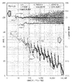
図13には、発明者らが、データ数nを2倍に増加させた場合におけるIIRフィルタと移動平均とを比較した結果が示されている。図13中、「+」で示される点P21は、入力値を示し、菱形の点P22は、入力値の標準偏差を示し、大きい丸形の点P23は、移動平均による出力値を示し、小さい丸形の点P24は、IIRフィルタによる出力値を示す。また、線L21は、理論上のノイズ低減率1/√nを示し、大きい菱形の点P25は、移動平均によるノイズ低減率を示し、小さい菱形の点P26は、IIRフィルタによるノイズ低減率を示す。図13からわかるように、IIRフィルタによっても、移動平均と同様に、おおよそ理論的な低減率に沿ってノイズを低減することができている。なお、移動平均及びIIRフィルタによるノイズ低減率は、(出力値の標準偏差)/(入力値の標準偏差)として算出される。
また、IIRフィルタによれば、図11,12に示されるように、レジスタを1つ用意するだけで演算が可能になる。これにより、図2に示されるように複数のレジスタを必要とする移動平均よりも少ないハードウェアリソースでフィルタリング処理を実行することができる。
なお、過去の出力値を1つだけ用いて新たな出力値を算出する例を説明したが、過去の複数の出力値を用いて新たな出力値を算出してもよい。また、現在の入力値に乗じる第1係数を(1/n)として、過去の出力値に乗じる第3係数を((n-1)/n)とする例を説明したが、第1係数及び第3係数はそれぞれ、上記説明と異なる値であってもよい。ただし、第1係数と一又は複数の第3係数はそれぞれ、正値であって、ゼロから1までの範囲内にあることが望ましい。さらに、第1係数と一又は複数の第3係数との総和は、1であることが望ましい。複数の第3係数はそれぞれ、異なる値であってもよい。
実施の形態3.
続いて、実施の形態3について、上述の実施の形態1との相違点を中心に説明する。なお、上記実施の形態と同一又は同等の構成については、同等の符号を用いるとともに、その説明を省略又は簡略する。上記実施の形態1では、閾値を予め規定されるパラメータとしていたが、この閾値は、ノイズの大きさに応じて定められることが望ましい。そこで、ノイズの大きさに応じて閾値を定める例について、以下、説明する。
続いて、実施の形態3について、上述の実施の形態1との相違点を中心に説明する。なお、上記実施の形態と同一又は同等の構成については、同等の符号を用いるとともに、その説明を省略又は簡略する。上記実施の形態1では、閾値を予め規定されるパラメータとしていたが、この閾値は、ノイズの大きさに応じて定められることが望ましい。そこで、ノイズの大きさに応じて閾値を定める例について、以下、説明する。
本実施の形態に係るフィルタリング装置20は、図14に示されるフィルタリング処理を実行する。このフィルタリング処理では、ステップS3に続いて、フィルタリング装置20は、過去の入力値の標準偏差に基づいて閾値を設定する(ステップS31)。具体的には、フィルタリング部22が、予め規定されたP個の入力値の標準偏差を算出して、算出した標準偏差のQ倍の値を閾値として設定する。
ここで、P及びQの値はそれぞれ、予めフィルタリング装置20が記憶する値であってもよいし、ユーザによって変更されてもよい。Pは、有効な標準偏差を得るためにある程度大きい回数であることが望ましく、例えば、32、64、又は128である。また、Qは、ノイズの大きさと計測対象の変位量とに応じて定められることが望ましい。例えば、変位量がステップ状に変化し、この変化量がノイズより顕著に大きい場合には、Pを比較的大きい値に設定することで、ノイズを低減しつつ少ない遅延で変位に追従する出力値を得ることができる。このようなPとして、例えば3或いは4とすることが考えられる。
以上、説明したように、本実施の形態に係るフィルタリング装置20は、入力値の標準偏差から閾値を算出して、この閾値に基づいて第1係数を変更する。これにより、時間の経過とともにノイズの大きさが変動するような場合にも、このノイズの大きさに応じた適当な閾値を用いて第1係数を変更して適当なフィルタリングを施すことができる。
図15には、発明者らが、過去の入力値の標準偏差に応じて閾値を規定した場合における入力値、出力値及び標準偏差のシミュレーションが示されている。図15中の「SD」は、標準偏差を示す。このシミュレーションでは、ステップ状に変化する変位量にノイズを重畳した値が入力値として用いられた。図15に示されるように、出力値は、ステップ状に変化する変位量に、少ない遅延で追従することができている。また、出力値がステップ状に推移しており、ノイズを低減することができている。
なお、上記実施の形態1における閾値を標準偏差に応じて規定する例について説明したが、図10の変形例における第1閾値及び第2閾値を、標準偏差に応じて規定してもよい。また、上記実施の形態2のように移動平均に代えてIIRフィルタを採用する場合にも、閾値を標準偏差に応じて規定することができる。
また、標準偏差に限らず、過去の入力値と出力値との少なくとも一方のバラつきに関する統計量に応じて閾値を規定してもよい。このような統計量として、出力値と入力値との差のバラつき、この差のヒストグラムにおけるピーク値或いはピーク位置、この差の偏差、及び、ヒストグラムに関する統計量の時間変動、のうち1つ又は複数に応じて閾値を規定することが考えられる。
以上、本発明の実施の形態について説明したが、本発明は上記実施の形態によって限定されるものではない。
例えば、センサ装置10がレーザ変位装置である例について説明したが、これには限定されず、センサ装置10は、他のセンシング機器であってもよい。
また、図4のハードウェア構成において入力部44及び出力部45は、ユーザとの間で情報を授受するユーザインタフェースを形成してもよい。
また、第1係数を変更する際の変更量は、上述の例に限定されず、ユーザが任意に設定してもよい。また、第1係数の初期値は、上述の例に限定されず、ユーザが任意に設定してもよい。
また、センサ装置10がフィルタリング装置20を内蔵する例について説明したが、これには限定されない。例えば、センサ装置10とフィルタリング装置20とが異なる装置として構成されてもよい。また、センサ装置10とフィルタリング装置20とが一体的に構成される場合も考えられる。この場合には、プロセッサ41が計測部14を実現し、取得部21と計測部14とが一体的に形成されてもよい。
また、上記実施の形態1,2に係るフィルタリング装置20は、以下の式(5)に従って出力値を算出してもよい。

ただし、上記式(5)において、Doutiは新たに算出される出力値であって、Diniは現在の入力値であって、a0は第1係数であって、Dini-kは過去の入力値であって、akは第2係数であって、Douti-mは過去の出力値であって、bmは第3係数である。上記式(5)右辺のakを含む第2項とbmを含む第3項とのいずれか一方のみが有効となる。換言すると、akとbmの一方が正値になり他方がゼロとなる。上記実施の形態1は、式(5)の右辺の第3項を省略して、a0=ak=(1/n)とした場合に相当する。この場合においては、移動平均の対象となるデータ数は、K+1となる。また、上記実施の形態2は、式(5)の右辺の第2項を省略して、M=1とした場合に相当する。この場合においては、a0=(1/n)となり、b1=((n-1)/n)となる。
上記式(5)において、演算に用いる過去の入力値の数K、及び演算に用いる過去の出力値の数Mは、任意に設定してよい。
また、フィルタリング装置20は、現在の入力値に応じて第1係数を変更すると、変更した第1係数を用いて現在の入力値から新たな出力値を算出したが、これには限定されない。例えば、値を変更した第1係数を、次回以降の入力値に適用してもよい。
また、フィルタリング装置20の機能は、専用のハードウェアによっても、また、通常のコンピュータシステムによっても実現することができる。
例えば、プロセッサ41によって実行されるプログラムP1を、コンピュータ読み取り可能な非一時的な記録媒体に格納して配布し、そのプログラムP1をコンピュータにインストールすることにより、上述の処理を実行する装置を構成することができる。このような記録媒体としては、例えばフレキシブルディスク、CD-ROM(Compact Disc Read-Only Memory)、DVD(Digital Versatile Disc)、MO(Magneto-Optical Disc)が考えられる。
また、プログラムP1をインターネットに代表される通信ネットワーク上のサーバ装置が有するディスク装置に格納しておき、例えば、搬送波に重畳させて、コンピュータにダウンロードするようにしてもよい。
また、通信ネットワークを介してプログラムP1を転送しながら起動実行することによっても、上述の処理を達成することができる。
さらに、プログラムP1の全部又は一部をサーバ装置上で実行させ、その処理に関する情報をコンピュータが通信ネットワークを介して送受信しながらプログラムを実行することによっても、上述の処理を達成することができる。
なお、上述の機能を、OS(Operating System)が分担して実現する場合又はOSとアプリケーションとの協働により実現する場合等には、OS以外の部分のみを媒体に格納して配布してもよく、また、コンピュータにダウンロードしてもよい。
また、フィルタリング装置20の機能を実現する手段は、ソフトウェアに限られず、その一部又は全部を、回路を含む専用のハードウェアによって実現してもよい。
本発明は、本発明の広義の精神と範囲を逸脱することなく、様々な実施の形態及び変形が可能とされるものである。また、上述した実施の形態は、本発明を説明するためのものであり、本発明の範囲を限定するものではない。つまり、本発明の範囲は、実施の形態ではなく、請求の範囲によって示される。そして、請求の範囲内及びそれと同等の発明の意義の範囲内で施される様々な変形が、本発明の範囲内とみなされる。
本発明は、ノイズを低減するフィルタリングに適している。
10 センサ装置、 11 発光素子、 12 レンズ、 13 受光素子、 14 計測部、 15 素子制御部、 16 システム制御部、 20 フィルタリング装置、 21 取得部、 22 フィルタリング部、 23 出力部、 30 ワーク、 41 プロセッサ、 42 主記憶部、 43 補助記憶部、 44 入力部、 45 出力部、 46 通信部、 47 内部バス、 L11 破線、 L21 線、 P1 プログラム、 P21~P26 点。
Claims (12)
- 繰り返し入力される入力値を取得する取得手段と、
前記入力値に含まれるノイズを低減するフィルタリングにより出力値を得るフィルタリング手段と、を備え、
前記フィルタリング手段は、現在の前記入力値と過去の前記出力値との差が第1閾値を超える場合に、該過去の前記出力値を得るための重みよりも大きい重みで現在の前記入力値の重み付けをすることで新たな前記出力値を得る、
フィルタリング装置。 - 前記フィルタリング手段は、前記差が第2閾値を下回る場合に、過去の前記出力値を得るための重みよりも小さい重みで現在の前記入力値の重み付けをすることで新たな前記出力値を得る、
請求項1に記載のフィルタリング装置。 - 前記フィルタリング手段は、
移動平均により前記出力値を算出し、
前記差が前記第1閾値を超える場合に、移動平均の対象とする前記入力値の数を減少させることで現在の前記入力値の重みを大きくして新たな前記出力値を算出する、
請求項1又は2に記載のフィルタリング装置。 - 現在の前記入力値の重みは、移動平均の対象とする前記入力値の数の逆数に等しい、
請求項3に記載のフィルタリング装置。 - 前記フィルタリング手段は、現在の前記入力値と過去の前記出力値との重み付け平均として新たな前記出力値を算出する、
請求項1又は2に記載のフィルタリング装置。 - 前記フィルタリング手段は、現在の前記入力値の重みの初期値を1に設定する、
請求項1から5のいずれか一項に記載のフィルタリング装置。 - 現在の前記入力値の重みは、ゼロから1の範囲内の値であって、
前記フィルタリング手段は、前記差が前記第1閾値を超える場合に、現在の前記入力値の重みを1に設定する、
請求項1から6のいずれか一項に記載のフィルタリング装置。 - 前記フィルタリング手段は、前記差が連続して前記第1閾値を超える場合に、現在の前記入力値の重みを大きくする、
請求項1から7のいずれか一項に記載のフィルタリング装置。 - 前記第1閾値は、過去の前記入力値に関する統計量に基づいて規定される、
請求項1から8のいずれか一項に記載のフィルタリング装置。 - 計測値を繰り返し出力する計測手段と、
ノイズを低減するフィルタリングを前記計測値に施す請求項1から9のいずれか一項に記載のフィルタリング装置と、
を備えるセンサ装置。 - 繰り返し入力される入力値を取得する取得ステップと、
前記入力値に含まれるノイズが低減された出力値を得るフィルタリングステップと、
を含み、
前記フィルタリングステップでは、現在の前記入力値と過去の前記出力値との差が第1閾値を超える場合に、該過去の前記出力値を得るための重みとは異なる重みで現在の前記入力値の重み付けをすることで新たな前記出力値を得る、フィルタリング方法。 - コンピュータを、
繰り返し入力される入力値を取得する取得手段、
前記入力値に含まれるノイズが低減された出力値を得るフィルタリング手段、として機能させ、
前記フィルタリング手段は、現在の前記入力値と過去の前記出力値との差が第1閾値を超える場合に、該過去の前記出力値を得るための重みとは異なる重みで現在の前記入力値の重み付けをすることで新たな前記出力値を得る、プログラム。
Priority Applications (4)
| Application Number | Priority Date | Filing Date | Title |
|---|---|---|---|
| CN201880095293.2A CN112384752A (zh) | 2018-07-06 | 2018-07-06 | 滤波装置、传感器装置、滤波方法及程序 |
| JP2019511514A JP6524371B1 (ja) | 2018-07-06 | 2018-07-06 | フィルタリング装置、センサ装置、フィルタリング方法及びプログラム |
| US17/252,281 US11365962B2 (en) | 2018-07-06 | 2018-07-06 | Filtering device, sensor device, filtering method and program |
| PCT/JP2018/025718 WO2020008627A1 (ja) | 2018-07-06 | 2018-07-06 | フィルタリング装置、センサ装置、フィルタリング方法及びプログラム |
Applications Claiming Priority (1)
| Application Number | Priority Date | Filing Date | Title |
|---|---|---|---|
| PCT/JP2018/025718 WO2020008627A1 (ja) | 2018-07-06 | 2018-07-06 | フィルタリング装置、センサ装置、フィルタリング方法及びプログラム |
Publications (1)
| Publication Number | Publication Date |
|---|---|
| WO2020008627A1 true WO2020008627A1 (ja) | 2020-01-09 |
Family
ID=66730593
Family Applications (1)
| Application Number | Title | Priority Date | Filing Date |
|---|---|---|---|
| PCT/JP2018/025718 Ceased WO2020008627A1 (ja) | 2018-07-06 | 2018-07-06 | フィルタリング装置、センサ装置、フィルタリング方法及びプログラム |
Country Status (4)
| Country | Link |
|---|---|
| US (1) | US11365962B2 (ja) |
| JP (1) | JP6524371B1 (ja) |
| CN (1) | CN112384752A (ja) |
| WO (1) | WO2020008627A1 (ja) |
Cited By (1)
| Publication number | Priority date | Publication date | Assignee | Title |
|---|---|---|---|---|
| JPWO2021149240A1 (ja) * | 2020-01-24 | 2021-07-29 |
Families Citing this family (1)
| Publication number | Priority date | Publication date | Assignee | Title |
|---|---|---|---|---|
| US11092470B2 (en) * | 2019-09-13 | 2021-08-17 | Micro Motion Inc. | Magnetic flowmeter with noise adaptive dead time |
Citations (6)
| Publication number | Priority date | Publication date | Assignee | Title |
|---|---|---|---|---|
| JP2012018199A (ja) * | 2010-07-06 | 2012-01-26 | Konica Minolta Business Technologies Inc | 画像形成装置 |
| JP2012031776A (ja) * | 2010-07-30 | 2012-02-16 | Toyota Motor Corp | 内燃機関の燃料噴射量制御装置 |
| JP2013088290A (ja) * | 2011-10-18 | 2013-05-13 | Nanao Corp | 動体判別装置、センサのゆらぎ検出装置、表示装置、動体判別方法及びセンサのゆらぎ検出方法 |
| JP2015503157A (ja) * | 2011-11-28 | 2015-01-29 | ネオノード インコーポレイテッド | 交替反射レンズファセットを有する光学要素 |
| JP2016116221A (ja) * | 2014-12-10 | 2016-06-23 | 三星電子株式会社Samsung Electronics Co.,Ltd. | 3d表示のための装置及び方法 |
| JP2017044626A (ja) * | 2015-08-28 | 2017-03-02 | 三陽工業株式会社 | レール計測装置、レール計測方法、およびプログラム |
Family Cites Families (17)
| Publication number | Priority date | Publication date | Assignee | Title |
|---|---|---|---|---|
| DE2210881C2 (de) * | 1972-03-07 | 1973-12-06 | Metabowerke Kg, Closs, Rauch & Schnizler, 7440 Nuertingen | Verzahnungsmeßgerat |
| JP3789728B2 (ja) * | 1999-08-10 | 2006-06-28 | ジーイー横河メディカルシステム株式会社 | プロジェクションデータ補正方法および装置並びに放射線断層撮像装置 |
| JP4270733B2 (ja) * | 2000-09-14 | 2009-06-03 | 株式会社東芝 | 画像のサイズ変換方法及び装置 |
| US7711044B1 (en) * | 2001-10-29 | 2010-05-04 | Trident Microsystems (Far East) Ltd. | Noise reduction systems and methods |
| US9052777B2 (en) | 2001-11-02 | 2015-06-09 | Neonode Inc. | Optical elements with alternating reflective lens facets |
| JP4430466B2 (ja) | 2004-06-22 | 2010-03-10 | 株式会社キーエンス | 光学式変位計 |
| DE102004036069B4 (de) | 2004-07-24 | 2017-04-06 | Dr. Johannes Heidenhain Gmbh | Verfahren und Vorrichtung zum Bilden von rauschgefilterten Ausgangswerten aus rauschbehafteten Eingangswerten |
| JP4745032B2 (ja) | 2005-11-18 | 2011-08-10 | シャープ株式会社 | フィルタ装置 |
| JP4914188B2 (ja) * | 2006-11-27 | 2012-04-11 | 富士重工業株式会社 | 平滑化フィルタ装置および速度検出装置 |
| CN101888355A (zh) * | 2010-04-22 | 2010-11-17 | 深圳市云海通讯股份有限公司 | 一种自适应滤波器及滤波方法 |
| JP5218494B2 (ja) | 2010-07-30 | 2013-06-26 | オムロン株式会社 | 変位センサ |
| JP5925390B1 (ja) * | 2014-12-02 | 2016-05-25 | 三菱電機株式会社 | 変位センサ、変位検出装置及び変位検出方法 |
| JP2016183882A (ja) | 2015-03-25 | 2016-10-20 | 住友電気工業株式会社 | Ofケーブルの評価方法およびofケーブルの評価装置 |
| WO2016165116A1 (zh) * | 2015-04-16 | 2016-10-20 | 中国科学院自动化研究所 | 一种基于噪声相关性的视频去噪系统 |
| US10270973B2 (en) * | 2015-12-08 | 2019-04-23 | Canon Kabushiki Kaisha | Control device and imaging apparatus with a subject selectable mode with higher image blur correction |
| DE102016224636B3 (de) | 2016-12-09 | 2018-01-25 | Robert Bosch Gmbh | Verfahren zur Adaption einer elektronischen Filtereinheit, eine elektronische Filtereinheit sowie eine Vorrichtung mit einer solchen Filtereinheit |
| WO2019051841A1 (zh) * | 2017-09-18 | 2019-03-21 | 深圳市汇顶科技股份有限公司 | 确定滤波器系数的方法及其装置、终端 |
-
2018
- 2018-07-06 WO PCT/JP2018/025718 patent/WO2020008627A1/ja not_active Ceased
- 2018-07-06 US US17/252,281 patent/US11365962B2/en active Active
- 2018-07-06 JP JP2019511514A patent/JP6524371B1/ja not_active Expired - Fee Related
- 2018-07-06 CN CN201880095293.2A patent/CN112384752A/zh active Pending
Patent Citations (6)
| Publication number | Priority date | Publication date | Assignee | Title |
|---|---|---|---|---|
| JP2012018199A (ja) * | 2010-07-06 | 2012-01-26 | Konica Minolta Business Technologies Inc | 画像形成装置 |
| JP2012031776A (ja) * | 2010-07-30 | 2012-02-16 | Toyota Motor Corp | 内燃機関の燃料噴射量制御装置 |
| JP2013088290A (ja) * | 2011-10-18 | 2013-05-13 | Nanao Corp | 動体判別装置、センサのゆらぎ検出装置、表示装置、動体判別方法及びセンサのゆらぎ検出方法 |
| JP2015503157A (ja) * | 2011-11-28 | 2015-01-29 | ネオノード インコーポレイテッド | 交替反射レンズファセットを有する光学要素 |
| JP2016116221A (ja) * | 2014-12-10 | 2016-06-23 | 三星電子株式会社Samsung Electronics Co.,Ltd. | 3d表示のための装置及び方法 |
| JP2017044626A (ja) * | 2015-08-28 | 2017-03-02 | 三陽工業株式会社 | レール計測装置、レール計測方法、およびプログラム |
Cited By (2)
| Publication number | Priority date | Publication date | Assignee | Title |
|---|---|---|---|---|
| JPWO2021149240A1 (ja) * | 2020-01-24 | 2021-07-29 | ||
| WO2021149240A1 (ja) * | 2020-01-24 | 2021-07-29 | 理化工業株式会社 | 演算装置、指示計、温度調節計、および方法 |
Also Published As
| Publication number | Publication date |
|---|---|
| US20210148693A1 (en) | 2021-05-20 |
| US11365962B2 (en) | 2022-06-21 |
| JP6524371B1 (ja) | 2019-06-05 |
| JPWO2020008627A1 (ja) | 2020-07-09 |
| CN112384752A (zh) | 2021-02-19 |
Similar Documents
| Publication | Publication Date | Title |
|---|---|---|
| TWI440269B (zh) | 先進的雷射波長控制技術 | |
| JP2021002819A (ja) | フィルタリング装置、センサ装置、フィルタリング方法、およびフィルタリングプログラム | |
| JP6486888B2 (ja) | 移動平均フィルタの動作制御方法 | |
| US10564658B2 (en) | Servo control apparatus, servo control method and computer-readable recording medium | |
| WO2016045095A1 (zh) | 一种校准检测距离的方法、装置及设备 | |
| WO2021042382A1 (zh) | 激光雷达测距方法、装置、计算机设备和存储介质 | |
| JP5958392B2 (ja) | 時系列計測信号のノイズ低減装置 | |
| WO2020008627A1 (ja) | フィルタリング装置、センサ装置、フィルタリング方法及びプログラム | |
| JP2016161343A (ja) | 自動調整機能を有するエンコーダの信号処理装置 | |
| CN106681536B (zh) | 非暂时性电脑可读取媒体及影像感测装置 | |
| JP2016208556A (ja) | デマンド予測装置及びデマンド予測方法 | |
| JP2011226924A (ja) | 追尾装置 | |
| RU2622852C1 (ru) | Адаптивное цифровое сглаживающее и прогнозирующее устройство | |
| JP6598029B2 (ja) | アクティブ消音装置 | |
| JP6388754B1 (ja) | 信号処理装置、センサ装置および信号処理方法 | |
| JP6000652B2 (ja) | パルスモータ制御装置およびパルス信号生成方法 | |
| CN114722343A (zh) | 一种离合器位置信号滤波方法、装置、存储介质及终端 | |
| CN116952273A (zh) | 一种时间标定方法、电子设备及计算机可读存储介质 | |
| JP2010181200A (ja) | レーダ信号処理装置 | |
| WO2020121722A1 (ja) | 推定装置、推定方法および推定プログラム | |
| JP2017033464A (ja) | 状態推定装置 | |
| KR102900246B1 (ko) | 적응 필터 설정 방법 및 이를 위한 전자 장치 | |
| JP7258247B2 (ja) | レーダ信号処理装置、レーダ装置、及びレーダ信号処理方法 | |
| TWI557729B (zh) | 語音信號處理裝置及語音信號處理方法 | |
| JP7814627B1 (ja) | 信号処理装置、信号処理方法およびプログラム |
Legal Events
| Date | Code | Title | Description |
|---|---|---|---|
| ENP | Entry into the national phase |
Ref document number: 2019511514 Country of ref document: JP Kind code of ref document: A |
|
| 121 | Ep: the epo has been informed by wipo that ep was designated in this application |
Ref document number: 18925545 Country of ref document: EP Kind code of ref document: A1 |
|
| NENP | Non-entry into the national phase |
Ref country code: DE |
|
| 122 | Ep: pct application non-entry in european phase |
Ref document number: 18925545 Country of ref document: EP Kind code of ref document: A1 |