WO2020008499A1 - 内視鏡リプロセッサ - Google Patents
内視鏡リプロセッサ Download PDFInfo
- Publication number
- WO2020008499A1 WO2020008499A1 PCT/JP2018/025063 JP2018025063W WO2020008499A1 WO 2020008499 A1 WO2020008499 A1 WO 2020008499A1 JP 2018025063 W JP2018025063 W JP 2018025063W WO 2020008499 A1 WO2020008499 A1 WO 2020008499A1
- Authority
- WO
- WIPO (PCT)
- Prior art keywords
- nozzle
- advance
- retreat
- flow path
- bottle
- Prior art date
Links
Images


Classifications
-
- A—HUMAN NECESSITIES
- A61—MEDICAL OR VETERINARY SCIENCE; HYGIENE
- A61L—METHODS OR APPARATUS FOR STERILISING MATERIALS OR OBJECTS IN GENERAL; DISINFECTION, STERILISATION OR DEODORISATION OF AIR; CHEMICAL ASPECTS OF BANDAGES, DRESSINGS, ABSORBENT PADS OR SURGICAL ARTICLES; MATERIALS FOR BANDAGES, DRESSINGS, ABSORBENT PADS OR SURGICAL ARTICLES
- A61L2/00—Methods or apparatus for disinfecting or sterilising materials or objects other than foodstuffs or contact lenses; Accessories therefor
- A61L2/16—Methods or apparatus for disinfecting or sterilising materials or objects other than foodstuffs or contact lenses; Accessories therefor using chemical substances
- A61L2/18—Liquid substances or solutions comprising solids or dissolved gases
-
- A—HUMAN NECESSITIES
- A61—MEDICAL OR VETERINARY SCIENCE; HYGIENE
- A61B—DIAGNOSIS; SURGERY; IDENTIFICATION
- A61B1/00—Instruments for performing medical examinations of the interior of cavities or tubes of the body by visual or photographical inspection, e.g. endoscopes; Illuminating arrangements therefor
- A61B1/12—Instruments for performing medical examinations of the interior of cavities or tubes of the body by visual or photographical inspection, e.g. endoscopes; Illuminating arrangements therefor with cooling or rinsing arrangements
- A61B1/121—Instruments for performing medical examinations of the interior of cavities or tubes of the body by visual or photographical inspection, e.g. endoscopes; Illuminating arrangements therefor with cooling or rinsing arrangements provided with means for cleaning post-use
-
- A—HUMAN NECESSITIES
- A61—MEDICAL OR VETERINARY SCIENCE; HYGIENE
- A61B—DIAGNOSIS; SURGERY; IDENTIFICATION
- A61B1/00—Instruments for performing medical examinations of the interior of cavities or tubes of the body by visual or photographical inspection, e.g. endoscopes; Illuminating arrangements therefor
- A61B1/12—Instruments for performing medical examinations of the interior of cavities or tubes of the body by visual or photographical inspection, e.g. endoscopes; Illuminating arrangements therefor with cooling or rinsing arrangements
-
- A—HUMAN NECESSITIES
- A61—MEDICAL OR VETERINARY SCIENCE; HYGIENE
- A61L—METHODS OR APPARATUS FOR STERILISING MATERIALS OR OBJECTS IN GENERAL; DISINFECTION, STERILISATION OR DEODORISATION OF AIR; CHEMICAL ASPECTS OF BANDAGES, DRESSINGS, ABSORBENT PADS OR SURGICAL ARTICLES; MATERIALS FOR BANDAGES, DRESSINGS, ABSORBENT PADS OR SURGICAL ARTICLES
- A61L2202/00—Aspects relating to methods or apparatus for disinfecting or sterilising materials or objects
- A61L2202/10—Apparatus features
- A61L2202/12—Apparatus for isolating biocidal substances from the environment
- A61L2202/121—Sealings, e.g. doors, covers, valves, sluices
-
- A—HUMAN NECESSITIES
- A61—MEDICAL OR VETERINARY SCIENCE; HYGIENE
- A61L—METHODS OR APPARATUS FOR STERILISING MATERIALS OR OBJECTS IN GENERAL; DISINFECTION, STERILISATION OR DEODORISATION OF AIR; CHEMICAL ASPECTS OF BANDAGES, DRESSINGS, ABSORBENT PADS OR SURGICAL ARTICLES; MATERIALS FOR BANDAGES, DRESSINGS, ABSORBENT PADS OR SURGICAL ARTICLES
- A61L2202/00—Aspects relating to methods or apparatus for disinfecting or sterilising materials or objects
- A61L2202/10—Apparatus features
- A61L2202/12—Apparatus for isolating biocidal substances from the environment
- A61L2202/123—Connecting means
-
- A—HUMAN NECESSITIES
- A61—MEDICAL OR VETERINARY SCIENCE; HYGIENE
- A61L—METHODS OR APPARATUS FOR STERILISING MATERIALS OR OBJECTS IN GENERAL; DISINFECTION, STERILISATION OR DEODORISATION OF AIR; CHEMICAL ASPECTS OF BANDAGES, DRESSINGS, ABSORBENT PADS OR SURGICAL ARTICLES; MATERIALS FOR BANDAGES, DRESSINGS, ABSORBENT PADS OR SURGICAL ARTICLES
- A61L2202/00—Aspects relating to methods or apparatus for disinfecting or sterilising materials or objects
- A61L2202/10—Apparatus features
- A61L2202/15—Biocide distribution means, e.g. nozzles, pumps, manifolds, fans, baffles, sprayers
-
- A—HUMAN NECESSITIES
- A61—MEDICAL OR VETERINARY SCIENCE; HYGIENE
- A61L—METHODS OR APPARATUS FOR STERILISING MATERIALS OR OBJECTS IN GENERAL; DISINFECTION, STERILISATION OR DEODORISATION OF AIR; CHEMICAL ASPECTS OF BANDAGES, DRESSINGS, ABSORBENT PADS OR SURGICAL ARTICLES; MATERIALS FOR BANDAGES, DRESSINGS, ABSORBENT PADS OR SURGICAL ARTICLES
- A61L2202/00—Aspects relating to methods or apparatus for disinfecting or sterilising materials or objects
- A61L2202/20—Targets to be treated
- A61L2202/24—Medical instruments, e.g. endoscopes, catheters, sharps
Definitions
- the present invention relates to an endoscope reprocessor.
- an endoscope reprocessor that performs a reprocessing process such as cleaning and disinfecting an endoscope used for a subject using a disinfecting solution, a cleaning solution, a chemical solution such as alcohol, or the like.
- the endoscope reprocessor is connected to the bottle storing the drug solution by the bottle connector, and acquires the drug solution used for the reprocessing from the bottle.
- the bottle connector is opened so as to communicate with the inside of the sealed bottle in accordance with the connection with the bottle, and is closed so that the residual liquid does not leak outside upon removal from the bottle.
- Japanese Unexamined Patent Publication No. 7-18614 discloses a female connector having a valve for closing a liquid passage hole from below, and a male connector having a spring for urging a valve body against a valve seat, Disclosed is a coupling device in which, when a male connector is removed from a female connector, the female connector automatically closes the container, as well as the male connector, so that the liquid remaining in the bottle does not leak.
- the bottle fitting may be subjected to a water flow test in the inspection process during manufacturing.
- a water flow test when a water flow test is performed with a bottle connecting device as disclosed in Japanese Utility Model Publication No. 7-18614, the bottle connecting device can be maintained in an open state when not connected to the bottle. Is fixed by a jig or the like, passed through water, and dried. The jig is removed when the inspection process is completed.
- the conventional bottle connector is opened according to the connection with the bottle, and is closed according to the removal from the bottle, but in the state not connected to the bottle, to maintain the open state.
- a work such as fixing with a jig and a work for confirming whether or not the user has forgotten to remove the jig occur, which is troublesome.
- the present invention has a bottle connector that can prevent leakage of residual liquid when removed from a bottle, and can more easily maintain an open state when not connected to a bottle. And an endoscope reprocessor.
- An endoscope reprocessor includes a main body including a suction pump, a tube having one end communicating with the suction pump, and a bottle connector connected to the other end of the tube, and An endoscope reprocessor having a bottle including a drug solution storage unit and a nozzle communicating with the drug solution storage unit, wherein the bottle connection tool has a connection port connected to the tube, An insertion port into which the tip of the nozzle is inserted, a first flow path connecting the connection port and the insertion port, and disposed so as to be able to advance and retreat in the first flow path, and located at a first position in the first flow path.
- the first flow path is sealed, and a first advance / retreat portion that opens the first flow path when located at a second position closer to the connection port than the first position;
- a first fitting portion provided on the insertion port side, A first fastening portion for fastening the first advance / retreat portion when the advance / retreat portion is at the first position, wherein a third position in the nozzle is disposed within the nozzle so as to advance / retreat within the nozzle.
- the second advance / retreat section that opens the nozzle is provided.
- a second fitting portion that protrudes toward the nozzle opening and fits with the first fitting portion; and a second fastening portion that fastens the second advancing and retreating portion when the second advancing and retreating portion is at the third position. And a part.
- FIG. 1 is a block diagram illustrating an example of a configuration of an endoscope reprocessor according to an embodiment of the present invention.
- FIG. 3 is a cross-sectional view illustrating an example of a configuration of a chemical solution supply mechanism in the endoscope reprocessor according to the embodiment of the present invention.
- FIG. 3 is a cross-sectional view illustrating an example of a configuration of a chemical solution supply mechanism in the endoscope reprocessor according to the embodiment of the present invention.
- It is an expanded sectional view showing an example of composition of the 1st fitting part and the 2nd fitting part in the medical fluid supply mechanism of the endoscope reprocessor concerning the embodiment of the present invention.
- FIG. 1 is a block diagram illustrating an example of a configuration of an endoscope reprocessor according to an embodiment of the present invention.
- FIG. 3 is a cross-sectional view illustrating an example of a configuration of a chemical solution supply mechanism in the endoscope reprocessor according to the embodiment of
- FIG. 4 is a cross-sectional view showing a state in which a first fitting portion and a second fitting portion are fitted to each other in the medical solution supply mechanism of the endoscope reprocessor according to the embodiment of the present invention.
- FIG. 4 is a cross-sectional view showing a state in which a first fitting portion and a second fitting portion are fitted to each other in the medical solution supply mechanism of the endoscope reprocessor according to the embodiment of the present invention.
- FIG. 4 is a cross-sectional view illustrating an example of a state in which a bottle connector and a nozzle are connected to each other in the chemical liquid supply mechanism of the endoscope reprocessor according to the embodiment of the present invention.
- FIG. 4 is a cross-sectional view illustrating an example of a first flow path and a second flow path in the medical solution supply mechanism of the endoscope reprocessor according to the embodiment of the present invention.
- FIG. 4 is a cross-sectional view illustrating an example of a state in which a first advance / retreat portion is located at a second position in the medical solution supply mechanism of the endoscope reprocessor according to the embodiment of the present invention.
- It is an expanded sectional view showing an example of composition of the 1st fitting part and the 2nd fitting part in the medical fluid supply mechanism of the endoscope reprocessor concerning modification 1 of the embodiment of the present invention.
- FIG. 1 is a block diagram illustrating an example of the configuration of the endoscope reprocessor 1.
- the endoscope reprocessor 1 is a device that performs a reprocessing process of a contaminated endoscope and parts or accessories of the endoscope.
- the reprocessing treatment here is not particularly limited, and is not limited to rinsing with water, washing for removing dirt such as organic substances, disinfection for disabling predetermined microorganisms, removing all microorganisms, or sterilizing for killing, Alternatively, any of these combinations may be used.
- Accessories are not particularly limited, for example, a suction button attached to the endoscope at the time of use and removed from the endoscope at the time of reprocessing, an air / water button, or a tip cover that covers the end member of the endoscope. Is mentioned.
- the endoscope reprocessor 1 has a main body 11 and a top cover 12.
- the top cover 12 is provided on the top of the main body 11 so as to be openable and closable. When the top cover 12 is opened, the processing tank 21 is exposed to the outside.
- the main body 11 has a display panel 13 and an operation panel 14.
- the display panel 13 can display various information under the control of the control unit 94.
- the operation panel 14 allows a user to input an instruction. When a user inputs an instruction, the operation panel 14 outputs an instruction signal corresponding to the user input to the control unit 94.
- the processing tank 21 has a concave shape so as to house an endoscope for performing a reprocessing process and to store a liquid such as a cleaning liquid, a disinfecting liquid, a sterilizing liquid, or a rinsing liquid.
- the water supply hose connection port 31 is connected to a water tap via a water supply hose H.
- the water supply hose connection port 31 is connected to a water supply pipe 32.
- the water supply line 32 is connected to a three-way solenoid valve 33.
- the water supply pipe 32 is provided with a water supply solenoid valve 34, a check valve 35, and a water supply filter 36 in order from the water supply hose connection port 31 side.
- the circulation nozzle 37 communicates with one of the water supply pipe 32 and the liquid feed pipe 38 by the switching operation of the three-way solenoid valve 33.
- the circulation nozzle 37 discharges either the water supplied from the tap or the liquid taken in from the circulation port 40 to the processing tank 21.
- a liquid feed pump 39 is provided in the liquid feed pipe 38.
- the circulation port 40 is provided at the bottom of the processing tank 21 and communicates with the inflow pipe 41.
- a filter such as a wire mesh is attached to the circulation port 40 so that dirt can be collected.
- the inflow pipe 41 is branched into two and connected to the liquid feed pipe 38 and the channel pipe 42.
- the channel 42 is connected to the connector 43.
- the channel pipe 42 is provided with a channel pump 44 for performing liquid supply or air supply, a channel block 45, and an electromagnetic valve 46.
- the water leak detection connector 47 is connected to a water leak detection pump 49 via a water leak detection pipe 48.
- the channel 42 is also connected to a case 52 having a relief valve 51.
- the case conduit 52 is connected to an accessory case 54 via a tank bottom nozzle 53.
- the endoscope reprocessor 1 takes in the liquid in the processing tank 21 through the circulation port 40, discharges the liquid from the circulation nozzle 37, the connector 43, and the tank bottom nozzle 53, and circulates the liquid.
- the alcohol tank 61 is connected to the channel block 45 via the alcohol pipe 62. Alcohol is stored in the alcohol tank 61.
- the alcohol pipe 62 is provided with an alcohol pump 63 and a solenoid valve 64.
- the detergent tank 65 is connected to a detergent nozzle 67 via a detergent pipe 66. Detergent is stored in the detergent tank 65. In the detergent pipe 66, a detergent pump 68 is provided.
- the air supply pump 71 is connected to the channel block 45 via the air supply line 72.
- the air supply line 72 is provided with a check valve 73 and an air filter 74.
- the air supply pump 71 takes in air from the outside and sends the air to the channel block 45.
- the drain port 81 is provided at the bottom of the processing tank 21.
- the drain port 81 is connected to a disinfectant tank 82 and an external drain unit Ed via drain valves 81a and 81b that open and close the drain port 81.
- the drainage port 81 discharges the liquid in the processing tank 21 to the external drainage means Ed by driving the drainage pump 84 via the drainage valve 81a and the drainage line 83. Further, the drain port 81 discharges the disinfecting solution in the processing tank 21 to the disinfecting solution tank 82 through the drain valve 81b and the collecting pipe 85 so that the disinfecting solution can be collected.
- the disinfectant tank 82 stores the disinfectant.
- the disinfectant in the disinfectant tank 82 is heated by the heating unit 86.
- the disinfectant nozzle 87 is connected to a disinfectant tank 82 via a supply pipe 88.
- the supply line 88 is provided with a disinfecting solution filter 89 and a disinfecting solution pump 90.
- the disinfecting solution nozzle 87 discharges the disinfecting solution in the disinfecting solution tank 82 to the processing tank 21 by driving the disinfecting solution pump 90.
- the ultrasonic vibration unit 91, the heater 92, and the temperature detection sensor 93 are provided at the bottom of the processing tank 21.
- the control unit 94 controls each unit in the endoscope reprocessor 1.
- the control unit 94 has a memory 95 and a processor 96.
- the function of the control unit 94 is realized by the processor 96 reading and executing a program stored in the memory 95.
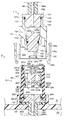
- FIGS. 2 and 3 are cross-sectional views showing an example of the configuration of the drug solution supply mechanism D in the endoscope reprocessor 1.
- FIG. FIG. 3 is a cross-sectional view of the chemical solution supply mechanism D cut in a direction orthogonal to the cut surface of FIG.
- the chemical solution supply mechanism D supplies the chemical solution to the disinfectant solution tank 82.
- the chemical is, for example, a disinfectant or a sterile liquid.
- the disinfectant tank 82 stores the disinfectant supplied from the chemical supply mechanism D in addition to the disinfectant collected from the processing tank 21 by the collection conduit 85.
- the chemical solution supply mechanism D may supply a disinfecting solution adjusted to a predetermined concentration, or may supply a stock solution of the disinfecting solution. When the stock solution of the disinfecting solution is supplied, the stock solution is diluted with the dilution water in the disinfecting solution tank 82 to be adjusted to a predetermined concentration.
- the chemical solution supply mechanism D has a bottle B provided with a suction pump 97, a tube 98, a bottle connector 111, and a nozzle 211.
- the bottle connector 111 is connected to the nozzle 211 (FIGS. 2 and 3).
- the suction pump 97 is connected to the disinfectant tank 82.
- the suction pump 97 sucks the disinfecting solution in the bottle B and discharges it to the disinfecting solution tank 82 under the control of the control unit 94.
- the tube 98 is made of, for example, rubber or the like. One end of the tube 98 communicates with the suction pump 97, and the other end is connected to the bottle connector 111.
- the bottle connector 111 is made of, for example, resin or the like.
- the bottle connector 111 is attached to the nozzle 211 of the bottle B.
- the bottle connector 111 has a tube main body 121, a first advance / retreat portion 131, and a tube connection portion 141.
- the cylinder main body 121 In the cylinder main body 121, one end 121a and the other end 121b opposite to the one end 121a communicate with each other.
- the other end 121b is provided with an insertion port 121c.
- the cylinder main body 121 has an inner peripheral portion 122 on one end side, an inner ring portion 123, an inner peripheral portion 124 on the other end side, a resistance member 125, and a locking member 126.
- One end side inner peripheral portion 122 extends from the inner edge of one end portion 121a toward the other end.
- One end side inner peripheral portion 122 has a smaller inner diameter than the other end side inner peripheral portion 124.
- the inner ring portion 123 extends inside the cylinder main body 121 from the one end side inner peripheral portion 122 toward the other end and radially inward.
- the inner ring part 123 has an inner diameter smaller than the one end side inner peripheral part 122.
- the other end side inner peripheral portion 124 extends from the insertion port 121c toward one end.
- the other end side inner peripheral portion 124 has a larger inner diameter than the one end side inner peripheral portion 122.
- the other end side inner peripheral portion 124 extends inward in the radial direction, and intersects the outer peripheral surface of the inner ring portion 123.
- An annular groove 124a is provided between the outer peripheral surface of the inner ring portion 123 and the inner peripheral portion 124 at the other end.
- the resistance member 125 is constituted by, for example, a plunger including a ball and a spring for urging the ball.
- the resistance member 125 generates a contact resistance Ra between the resistance member 125 and the first retreating part 131.
- the resistance member 125 is provided so that the ball hits the outer edge on one end side of the first advance / retreat portion 131 at the position P1 in the inner peripheral portion 122 on one end side.
- the resistance member 125 may be configured by a fastening member such as a pin instead of the ball.
- the locking member 126 includes a protruding piece 126 a protruding from the outer peripheral surface of the cylinder main body 121, a knob 126 b extending on one end side of the protruding piece 126 a, and a hook extending on the other end side of the protruding piece 126 a. And a stop claw 126c.
- the first advance / retreat portion 131 is disposed in the first flow path L1 so as to be able to advance / retreat between a position P1 which is a first position and a position P2 (FIG. 7) which is a second position. Open and close.
- the first advance / retreat portion 131 includes a stopper 132, a packing 133 serving as a seal member, a frustum portion 134, a support member 135, and a first fitting portion 136.
- the stopper 132 is disposed inside the one end side inner peripheral portion 122, has an outer diameter larger than the inner diameter of the inner ring portion 123, is stopped by the inner ring portion 123, and prevents the first advance / retreat portion 131 from falling off. .
- the packing 133 is made of rubber or the like, has a ring shape, and is mounted in a circumferential groove continuously provided on the other end side of the stopper 132.
- the packing 133 generates a sliding resistance Rb between itself and the inner peripheral surface of the inner ring portion 123.
- the frustum portion 134 is continuously provided on the other end side of the circumferential groove in which the packing 133 is mounted.
- the frustum portion 134 has an outer diameter that gradually decreases toward the other end.
- the support member 135 extends from the frustum portion 134 toward the other end.
- the length of the support member 135 is adjusted in advance between the frustum portion 134 and the first fitting portion 136 to a length that accommodates the second fitting portion 236.
- the first fitting portion 136 is connected to the other end of the support member 135.
- the first fitting portion 136 has a ring shape so that the second fitting portion 236 can be inserted.
- the first fitting portion 136 has a predetermined inner diameter. That is, the first fitting portion 136 is provided on the insertion port 121c side of the first advance / retreat portion 131.
- the tube connecting portion 141 includes a mounting cylinder 142, an outwardly projecting portion 143, a packing 144, and a body portion 145.
- the mounting cylinder 142 is provided on one end side of the tube connection part 141.
- the mounting cylinder 142 has an elongated cylindrical shape, and has a connection port 142a at an end.
- the mounting cylinder 142 may have a non-slip on the outer peripheral surface near the end.
- the outwardly projecting portion 143 is continuously provided on the other end side of the mounting cylinder 142, and has a shape projecting radially outward so as to be hooked on the end surface of the one end portion 121a.
- the packing 144 is made of rubber or the like, has a ring shape, is mounted in a circumferential groove continuously provided on the other end side of the outwardly protruding portion 143, and is closely attached to the cylinder main body 121.
- the body 145 is arranged inside the inner peripheral portion 122 on one end side, and extends from the other end side of the circumferential groove on which the packing 144 is mounted.
- the other end opening 145a communicating with the connection port 142a by the internal flow path is provided on the end surface of the body portion 145.
- a projection 145b is provided around the other end opening 145a, and the end surface of the body portion 145 is connected to the first surface.
- a gap is formed between the advancing and retreating portion 131.
- the bottle B is made of, for example, resin or the like.
- a drug solution is stored in the drug solution storage unit B1.
- the bottle B has, for example, a rectangular box shape, but is not limited thereto, and may have another shape such as a cylindrical shape. Further, the bottle B may have a grip portion so that the bottle B can be transported.
- the nozzle 211 is provided on the outer wall of the bottle B and communicates with the drug solution storage section B1 via the bottle tube Tb.
- the tip of the nozzle 211 is inserted into the insertion port 121c.
- the nozzle 211 has a nozzle cylinder 221, a second advance / retreat part 231, a storage part connection part 241, and a cap 251.
- the tip 221b is provided with a nozzle opening 221c.
- the distal end portion 221b has an outer diameter smaller than the inner diameter of the inner peripheral portion 124 at the other end, and can be inserted into the insertion port 121c.
- the nozzle cylinder 221 has a base inner peripheral portion 222, a small inner peripheral portion 223, a distal inner peripheral portion 224, a resistance member 225, a protrusion 226, and a packing 227.
- the proximal end side inner peripheral portion 222 extends from the inner edge of the proximal end portion 221a toward the distal end.
- the small inner peripheral portion 223 extends from the proximal inner peripheral portion 222 in the distal direction.
- the small inner peripheral portion 223 has an inner diameter smaller than the proximal inner peripheral portion 222 and the distal inner peripheral portion 224.
- the distal-side inner peripheral portion 224 extends in the distal direction from the small inner peripheral portion 223 and communicates with the nozzle opening 221c.
- the resistance member 225 is constituted by, for example, a plunger provided with a ball and a spring for urging the ball.
- the second fastening portion generates a contact resistance Rc between itself and the second advance / retreat portion 231.
- the resistance member 225 is provided in the small inner peripheral portion 223 so that the ball enters the circumferential concave portion 234 of the second advance / retreat portion 231 at the position P3.
- the projection 226 protrudes from the outer peripheral surface of the nozzle tube 221 so as to be locked by the locking claw 126c.
- the packing 227 is made of rubber or the like, has a ring shape, is mounted on a peripheral groove provided on the outer peripheral surface near the distal end 221b, and slides on the inner surface of the annular groove 124a.
- the second advance / retreat section 231 moves forward / backward between the position P3, which is the third position, and the position P4 (FIG. 7), which is the fourth position, in the nozzle tube 221 to open and close the second flow path L2.
- the second advance / retreat portion 231 has a cylindrical shape.
- the second advance / retreat portion 231 includes a stopper 232, a packing 233, a circumferential concave portion 234, a support column 235, a second fitting portion 236, and a convex portion 237.
- the stopper 232 is arranged inside the proximal inner peripheral portion 222, has an outer diameter larger than the small inner peripheral portion 223, is stopped by the small inner peripheral portion 223, and prevents the second advance / retreat portion 231 from falling off. I do.
- the packing 233 is made of rubber or the like, has a ring shape, and is mounted in a circumferential groove continuously provided on the distal end side of the stopper 232.
- the packing 233 generates a sliding resistance Rd between the small inner peripheral portion 223 and the inner peripheral surface.
- the circumferential recess 234 is continuously provided on the tip side of the circumferential groove in which the packing 233 is mounted. At the bottom of the circumferential recess 234, a through hole 234a penetrating the inner periphery is provided. On the base end side of the through hole 234a, a closing wall 234b for closing an inner peripheral portion is continuously provided.
- the support column 235 is provided on the tip side of the closing wall 234b.
- the length of the support column 235 is such that the bottle fitting 111 and the nozzle 211 are connected to each other, the first advance / retreat portion 131 is located at the position P2, and the second advance / retreat portion 231 is located at the position P4.
- the length in which the portion 236 is fitted to the first fitting portion 136 is adjusted in advance.
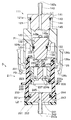
- FIG. 4 is an enlarged sectional view showing an example of the configuration of the first fitting portion 136 and the second fitting portion 236.
- the second fitting portion 236 is continuously provided on the distal end side of the support column 235, protrudes from the second advance / retreat portion 231 toward the nozzle opening 221 c of the nozzle 211, and the first fitting portion 136 is provided.
- the second fitting portion 236 includes a distal piece 236a, a proximal piece 236b, and a stop 236c.
- the distal piece 236a extends from the distal end to the proximal end of the support column 235 at a position corresponding to the inner edge of the other end of the first fitting portion 136 so as to be separated from the support column 235.
- the base end piece 236b extends from the front end piece 236a toward the base end toward the support column 235 at a position corresponding to the inner edge of one end of the fitted first fitting portion 136. Further, the proximal end piece 236b may extend in the proximal direction along the inner peripheral portion of the fitted first fitting portion 136.
- the abutting portion 236c extends outward from the distal end of the support column 235 in the meridional direction at a position where the abutting portion 236c is abutted against the frustum portion 134.
- the insertion resistance Ri for inserting the second fitting part 236 into the first fitting part 136 is generated according to the inclination angle ⁇ 1 of the tip piece 236a with respect to the insertion direction.
- the removal resistance Ro for removing the second fitting portion 236 from the first fitting portion 136 is generated in accordance with the inclination angle ⁇ 2 of the base piece 236b with respect to the removal direction.
- Withdrawal resistance Ro is set such that by removing second fitting portion 236 from first fitting portion 136, first advance / retreat portion 131 moves to position P1 and second advance / retreat portion 231 moves to position P3. , Are set to be larger than each of the movement resistances R1 and R2.
- the inclination angle ⁇ 2 is determined so that the removal resistance Ro is larger than each of the movement resistances R1 and R2.
- characteristics such as frictional force and side pressure of the packings 133 and 233, and frictional force and biasing force of the resistance members 125 and 225 are set so that each of the movement resistances R1 and R2 is smaller than the removal resistance Ro. May be determined in whole or in part.
- the inclination angles ⁇ 1 and ⁇ 2 are set to satisfy ⁇ 1 ⁇ 2 so that the insertion resistance Ri is smaller than the removal resistance Ro so that the bottle connector 111 and the nozzle 211 can be connected with a smaller force.
- the convex portion 237 is provided on the base end surface of the second advance / retreat portion 231, and forms a gap between the base end surface of the second advance / retreat portion 231 and the storage portion connection portion 241.
- the storage connection part 241 has a mounting cylinder 242, an outwardly projecting part 243, a packing 244, and a tip opening 245.
- the mounting cylinder 242 is provided on the base end side of the storage connection part 241.
- the mounting cylinder 242 has an elongated cylindrical shape, and has a bottle tube connection port 242a at an end.
- the mounting cylinder 242 has a non-slip 242b on the outer peripheral surface near the end.
- One end of the bottle tube Tb is attached to the attachment tube 242.
- the other end of the bottle tube Tb is disposed in the chemical solution storage section B1.
- the outward projecting portion 243 is continuously provided on the distal end side of the mounting cylinder 242, and has a shape projecting radially outward so as to hang on the end surface of the base end portion 221a.
- the packing 244 is made of rubber or the like, has a ring shape, is mounted in a circumferential groove continuously provided on the distal end side of the outwardly protruding portion 243, and is in close contact with the nozzle cylinder 221.
- the distal end opening 245 is provided on the distal end surface of the storage portion connection portion 241.
- the distal end opening 245 communicates with the bottle tube connection port 242a.
- the cap 251 is attached to the base end 221a.
- the cap 251 has a central hole 252 in which the mounting cylinder 242 is arranged inside.
- the cap 251 has an outer peripheral portion 253 extending in the distal direction along the outer peripheral surface of the base end portion 221a.
- the position P1 is a position where the packing 133 is disposed inside the inner ring portion 123.
- the first advancing / retracting portion 131 closes the inside of the inner ring portion 123 with the packing 133 to shut off the first flow path L1 and closes the bottle connector 111.
- the first advancing / retreating portion 131 has a movement resistance R1 obtained by combining the contact resistance Ra and the sliding resistance Rb.
- the resistance member 125 and the packing 133 constitute a first fastening portion for fastening the first advance / retreat section 131 when the first advance / retreat section 131 is at the position P1.
- the first fastening portion includes a resistance member 125 arranged on the inner periphery of the first flow path L1.
- the first fastening portion provides the first advance / retreat portion 131 with a movement resistance R1 smaller than the extraction resistance Ro for extracting the second engagement portion 236 from the first engagement portion 136 at the position P1.
- the position P2 is a position where the packing 133 is arranged at one end side of the inner ring portion 123.
- a gap is formed between the first advance / retreat portion 131 and the inner ring portion 123, the first flow path L1 is communicated, and the bottle connector 111 is opened.
- the first flow path L ⁇ b> 1 includes the other end side inner peripheral portion 124, a gap between the first advance / retreat portion 131 and the inner ring portion 123, a gap between the first advance / retreat portion 131 and the one end side inner peripheral portion 122, It is constituted by a gap between the part 145 and the first advance / retreat part 131 and an internal flow path of the tube connection part 141, and connects the connection port 142a and the insertion port 121c.
- the first advance / retreat portion 131 is disposed so as to be able to advance / retreat in the first flow path L1, and seals the first flow path L1 when located at the first position P1 in the first flow path L1. When located at the second position on the connection port 142a side, the first flow path L1 is opened.
- the position P3 is a position where the packing 233 is arranged inside the small inner peripheral portion 223.
- the second advancing / retreating part 231 closes the inside of the small inner peripheral part 223 to block the second flow path L2, and closes the nozzle 211.
- the second advance / retreat unit 231 has a movement resistance R2 obtained by combining the contact resistance Rc and the sliding resistance Rd.
- the resistance member 225 and the packing 233 constitute a second fastening portion for fastening the second advance / retreat part 231 when the second advance / retreat part 231 is at the position P3.
- the second fastening portion includes a packing 233 which is a seal member arranged on the outer periphery of the second advance / retreat portion 231.
- the second fastening portion may be a packing (not shown) arranged on the inner periphery of the nozzle 211 instead of the packing 233.
- the second retaining portion gives the second advance / retreat portion 231 a movement resistance R2 smaller than the removal resistance Ro at the position P3.
- the position P4 is a position where the packing 233 is disposed on the base end side of the small inner peripheral portion 223.
- a gap is formed between the second advancing / retreating part 231 and the small inner peripheral part 223, which connects the second flow path L2 and opens the nozzle 211.
- the second flow path L2 includes a storage portion connection portion 241, a gap between the storage portion connection portion 241 and the second advance / retreat portion 231, a gap between the second advance / retreat portion 231 and the proximal inner peripheral portion 222, a circumferential concave portion 234, a through hole. 234a, the inside of the second advance / retreat part 231, and the inner peripheral part 224 on the distal end side, and connects the bottle tube connection port 242a and the nozzle opening 221c.
- the second advance / retreat portion 231 is disposed so as to be able to advance / retreat within the nozzle 211, seals the nozzle 211 when located at the third position in the nozzle 211, and is located at a fourth position closer to the chemical solution storage portion B1 than the third position. To do so, the nozzle 211 is opened.
- the first connecting / retracting portion 131 of the bottle connector 111 is located at the position P1, and is closed.
- the nozzle 211 is closed when the second retreating part 231 is located at the position P3.
- FIGS. 5 and 6 are cross-sectional views showing a state in which the first fitting part 136 and the second fitting part 236 are fitted to each other in the chemical liquid supply mechanism D.
- FIG. 6 is a cross-sectional view of the chemical solution supply mechanism D cut in a direction orthogonal to the cut surface of FIG.
- the second fitting portion 236 When the bottle connector 111 is fitted into the nozzle 211, the second fitting portion 236 is pressed against the first fitting portion 136. Further, when the bottle connector 111 is pushed in by an insertion force exceeding the insertion resistance Ri, the second fitting portion 236 is reduced in lateral width by elastic deformation, and is inserted into the first fitting portion 136. After passing through the first fitting portion 136, as shown in FIGS. 5 and 6, the second fitting portion 236 recovers from elastic deformation between the frustum portion 134 and the first fitting portion 136, and The fitting part 136 is fitted.
- FIG. 5 and FIG. 6 show that the insertion resistance Ri is configured to be smaller than each of the movement resistances R1 and R2, and the second fitting is performed before the first retreating part 131 and the second retreating part 231 move.
- the part 236 is inserted into the first fitting part 136.
- the insertion resistance Ri is configured to be greater than each of the movement resistances R1 and R2, and before the insertion resistance Ri is inserted into the first fitting part 136, the second fitting part 236 is moved to the first retreating part 131 and the second retreating part.
- the unit 231 may be pushed.
- FIG. 7 is a cross-sectional view showing an example of a state in which the bottle connector 111 and the nozzle 211 are connected to each other.
- the first advance / retreat portion 131 moves from the position P1 to the position P2. Then, the bottle connector 111 is opened. Further, the second advance / retreat portion 231 moves from the position P3 to the position P4, and the nozzle 211 is opened.
- the packing 227 closely adheres to the inner surface of the annular groove 124a, and makes the inside of the bottle connector 111 and the nozzle 211 watertight or airtight from the outside.
- FIG. 8 is a cross-sectional view for explaining an example of the first flow path L1 and the second flow path L2.
- connection port 142a and the bottle tube connection port 242a communicate with each other through the first flow path L1 and the second flow path L2.
- the removal resistance Ro is configured to be larger than each of the movement resistances R1 and R2, so that the second fitting part 236 is removed from the first fitting part 136.
- the first advance / retreat unit 131 moves from the position P2 to the position P1
- the second advance / retreat unit 231 moves from the position P4 to the position P3 (FIGS. 5 and 6).
- the stopper 132 is abutted against the inner ring portion 123
- the stopper 232 is abutted against the small inner peripheral portion 223, and the second fitting portion 236 is pulled out by the removal force exceeding the removal resistance Ro. Is removed from the first fitting portion 136.
- each of the bottle connector 111 and the nozzle 211 is closed, thereby preventing leakage of the residual liquid.
- the first retreating part 131 is located at the position P1, but the first retreating part 131 can be connected to the nozzle 211 even when the first retreating part 131 is at the position P2.
- FIG. 9 is a cross-sectional view showing an example of a state in which the first advance / retreat portion 131 is located at the position P2.
- the second fitting portion 236 It presses against the first fitting portion 136.
- the first fitting portion 136 and the second fitting portion 236 fit with each other.
- the second advance / retreat portion 231 moves to the position P3
- the bottle connector 111 and the nozzle 211 are connected to each other, and the connection port 142a and the bottle tube connection port 242a communicate with each other.
- the first advance / retreat unit 131 When the first advance / retreat unit 131 is pushed from the position P1 to the position P2 by the user's finger or jig, the first advance / retreat unit 131 stays at the position P2. Accordingly, the bottle connecting tool 111 maintains the open state even when the bottle connecting tool 111 is not connected to the nozzle 211, such as in an inspection process during manufacturing.
- the bottle connector 111 can be connected to the nozzle 211 regardless of whether the first advance / retreat portion 131 is located at the position P1 or the position P2. Therefore, for example, after the end of the inspection process, the first advance / retreat section 131 does not have to be returned from the position P2 to the position P1. Also, regardless of the position of the position P1 or the position P2, after being connected to the nozzle 211, the first advance / retreat portion 131 moves to the position P1 and shuts off the first flow path L1 in accordance with the removal from the nozzle 211. To prevent leakage of residual liquid.
- the endoscope reprocessor 1 can prevent the residual liquid from leaking when the bottle is removed from the bottle B, and more easily maintains the open state when the bottle is not connected to the bottle B. It has a bottle connector 111 that can be made to work.
- the second fitting portion 236 has a plurality of locking pieces, but may be a brush.
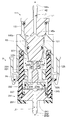
- FIG. 10 is an enlarged cross-sectional view showing an example of the configuration of the first fitting portion 336 and the second fitting portion 436 according to the first modification of the embodiment.
- FIG. 11 is a cross-sectional view illustrating a state where the first fitting portion 336 and the second fitting portion 436 are fitted to each other.
- the description of the same configuration as the other embodiments and modified examples is omitted.
- the first fitting portion 336 has a cylindrical shape. At the other end of the first fitting portion 336, an inward flange 337 is provided.
- the second fitting portion 436 has a brush whose bristle tip is directed to the base end.
- the bristle tip of the second fitting portion 436 falls down along the inner edge of the inward flange 337 and enters the first fitting portion 336 by elastic deformation, and the inside of the first fitting portion 336 Restores and spreads hair tips.
- the bristle tip of the second fitting portion 436 hooks on the inside of the inward flange 337, and generates a removal resistance Ro that is larger than the insertion resistance Ri.
- the second fitting portion 636 has a plurality of locking pieces, but the second fitting portion 636 may be a sponge.
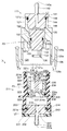
- FIG. 12 is an enlarged cross-sectional view illustrating an example of the configuration of the first fitting portion 536 and the second fitting portion 636 according to Modification 2 of the embodiment.
- FIG. 13 is a cross-sectional view illustrating a state where the first fitting portion 536 and the second fitting portion 636 are fitted to each other.
- the description of the same configuration as the other embodiments and modified examples is omitted.
- the first fitting portion 536 has a cylindrical shape.
- the second fitting portion 636 has a sponge.
- the second fitting portion 636 contracts due to elastic deformation, enters the first fitting portion 536, supplies water in the first fitting portion 536, and is larger than at the time of insertion. This causes a resistance Ro.
- first fitting portions 136, 336, 536 and the second fitting portions 236, 436, 636 are not limited to the configurations of the embodiment and the modification.
- the first fitting portions 136, 336, 536 and the second fitting portions 236, 436, 636 may be an engaging member or a sliding member that generates the withdrawal resistance Ro.
- the first fitting portions 136, 336, 536 and the second fitting portions 236, 436, 636 may be configured by a protruding member and a hanging member for hanging the protruding member.
- the resistance members 125 and 225 may be, for example, an engagement member or a slide member with the first advance / retreat portion 131 and the second advance / retreat portion 231. Further, the resistance members 125 and 225 may be provided in the first advance / retreat portion 131 and the second advance / retreat portion 231 so as to generate contact resistances Ra and Rc between the one end side inner peripheral portion 122 and the small inner peripheral portion 223. Good.
- the chemical liquid may be a chemical liquid other than the disinfecting liquid, such as a cleaning liquid or alcohol.
Abstract
内視鏡リプロセッサ1は、ボトル接続具111とノズル211を有する。ボトル接続具111は、第1位置に位置するときには第1流路L1を封止し、第2位置に位置するときには第1流路L1を開通する第1進退部131と、第1嵌合部136と、第1進退部131を留める第1留め部とを含む。ノズル211は、第3位置P3に位置するときにはノズル211を封止し、第4位置に位置するときにはノズル211を開通する第2進退部231と、第1嵌合部136に嵌合する第2嵌合部236と、第2進退部231を留める第2留め部と、が配置されている。
Description
本発明は、内視鏡リプロセッサに関する。
従来、消毒液、洗浄液、アルコール等の薬液を用い、被検体に使用された内視鏡の洗浄消毒等のリプロセス処理を行う内視鏡リプロセッサがある。内視鏡リプロセッサは、ボトル接続具によって薬液を貯留したボトルと接続し、ボトルからリプロセス処理に用いる薬液を取得する。ボトル接続具は、ボトルとの接続に応じて密閉されたボトル内と連通するように開状態にされ、一方、ボトルからの取外しに応じて残液が外部に漏れないように閉状態にされることがある。
例えば、日本国実公平7-18614号公報には、液体通過孔を下方から塞ぐ弁を有する雌コネクタと、弁体を弁座に押し付ける方向に付勢するバネを有する雄コネクタとを有し、雌コネクタから雄コネクタを取り外したとき、雄コネクタの自閉はもちろん、雌コネクタが容器を自動的に閉じることにより、ボトル内に残った液体が漏れてこない、連結具が開示される。
また、ボトル接続具は、製造時の検査工程において、通水テストが行われることがある。通水テストでは、日本国実公平7-18614号公報のようなボトル接続具で通水テストを行う場合には、ボトル接続具は、ボトルと接続していない状態において、開状態を維持できるように治具等によって固定され、通水され、乾燥される。治具は、検査工程が終了すると、取り外される。
しかし、従来のボトル接続具は、ボトルとの接続に応じて開状態になり、ボトルからの取外しに応じて閉状態になるものの、ボトルと接続していない状態において、開状態を維持させるためには、治具による固定等の作業、冶具の取り外し忘れがないか確認する作業が発生し、手間がかかる。
そこで、本発明は、ボトルから取り外した際の残液の漏れを防止することができ、かつ、より簡便にボトルと接続していない状態において開状態を維持させることができる、ボトル接続具を有する、内視鏡リプロセッサを提供することを目的とする。
本発明の一態様の内視鏡リプロセッサは、吸引ポンプと、一端が前記吸引ポンプに連通しているチューブと、前記チューブの他端に接続されたボトル接続具と、を含む本体部、および、薬液貯留部と、前記薬液貯留部に連通しているノズルとを含むボトルと、を有する内視鏡リプロセッサであって、前記ボトル接続具は、前記チューブに接続される接続口と、前記ノズルの先端を挿入する挿入口と、前記接続口と前記挿入口をつなぐ第1流路と、前記第1流路内を進退可能に配置され、前記第1流路における第1位置に位置するときには前記第1流路を封止し、前記第1位置よりも前記接続口側の第2位置に位置するときには前記第1流路を開通する第1進退部と、前記第1進退部のうち、前記挿入口側に設けられた第1嵌合部と、前記第1進退部が前記第1位置にあるときに、前記第1進退部を留める第1留め部と、を含み、前記ノズル内には、前記ノズル内を進退可能に配置され、前記ノズルにおける第3位置に位置するときには前記ノズルを封止し、前記第3位置よりも前記薬液貯留部側の第4位置に位置するときには前記ノズルを開通する第2進退部と、前記第2進退部から前記ノズルのノズル開口側に突出しており、前記第1嵌合部に嵌合する第2嵌合部と、前記第2進退部が前記第3位置にあるときに、前記第2進退部を留める第2留め部と、が配置されている。
以下、図面を参照しながら、本発明の実施形態を説明する。
(構成)
図1は、内視鏡リプロセッサ1の構成の一例を示すブロック図である。
図1は、内視鏡リプロセッサ1の構成の一例を示すブロック図である。
図1に示すように、内視鏡リプロセッサ1は、汚染された内視鏡、及び、内視鏡の部品又は付属品等のリプロセス処理を行う装置である。ここでいうリプロセス処理とは、特に限定されるものではなく、水によるすすぎ、有機物等の汚れを落とす洗浄、所定の微生物を無効化する消毒、全ての微生物を排除、もしくは、死滅させる滅菌、又は、これらの組み合わせのいずれであってもよい。付属品は、特に限定されず、例えば、使用時に内視鏡に装着されてリプロセス処理時に内視鏡から取り外される吸引ボタン、送気送水ボタン、又は内視鏡の先端部材を覆う先端カバーなどが挙げられる。
内視鏡リプロセッサ1は、本体部11及びトップカバー12を有する。
トップカバー12は、本体部11の上部に開閉可能に設けられる。トップカバー12を開けると、処理槽21は、外部に露出する。
本体部11は、表示パネル13及び操作パネル14を有する。表示パネル13は、制御部94の制御の下、各種情報を表示可能である。操作パネル14はユーザーの指示入力が可能である。ユーザーの指示入力があると、操作パネル14は、ユーザーの指示入力に応じた指示信号を制御部94に出力する。
処理槽21は、リプロセス処理を行う内視鏡を収容し、洗浄液、消毒液、滅菌液またはすすぎ液等の液体を貯留できるように凹形状を有する。
給水ホース接続口31は、給水ホースHを介して水道栓と接続される。また、給水ホース接続口31は、給水管路32と接続される。給水管路32は、三方電磁弁33と接続される。給水管路32には、給水ホース接続口31側から順に、給水電磁弁34と、逆止弁35と、給水フィルタ36とが設けられる。
循環ノズル37は、三方電磁弁33の切替え動作により、給水管路32と送液管路38のいずれか一方と連通する。循環ノズル37は、水道栓から供給された水、又は、循環口40から取り込まれた液体のいずれか一方を処理槽21に吐出する。
送液管路38には、送液ポンプ39が設けられる。
循環口40は、処理槽21の底部に設けられ、流入管路41と連通する。循環口40には、汚物を捕集できるように、金網等のフィルタが取り付けられる。
流入管路41は、2つに分岐し、送液管路38及びチャネル管路42と接続される。チャネル管路42は、コネクタ43と接続される。チャネル管路42には、送液又は送気を行うチャネルポンプ44、チャネルブロック45及び電磁弁46が設けられる。漏水検知コネクタ47は、漏水検知管路48を介して漏水検知ポンプ49に接続される。チャネル管路42は、リリーフ弁51を有するケース用管路52にも接続される。ケース用管路52は、槽底ノズル53を介し、付属品ケース54と接続される。
内視鏡リプロセッサ1は、循環口40によって処理槽21の液体を取り込み、循環ノズル37、コネクタ43及び槽底ノズル53から液体を吐出し、液体を循環させる。
アルコールタンク61は、アルコール管路62を介し、チャネルブロック45と接続される。アルコールタンク61には、アルコールが貯留される。アルコール管路62には、アルコールポンプ63及び電磁弁64が設けられる。
洗剤タンク65は、洗剤管路66を介し、洗剤ノズル67と接続される。洗剤タンク65には、洗剤が貯留される。洗剤管路66には、洗剤ポンプ68が設けられる。
送気ポンプ71は、送気管路72を介し、チャネルブロック45と接続される。送気管路72には、逆止弁73及びエアフィルタ74が設けられる。送気ポンプ71は、外部から空気を取り込み、チャネルブロック45に送気する。
排液口81は、処理槽21の底部に設けられる。排液口81は、排液口81を開閉する排液弁81a、81bを介し、消毒液タンク82及び外部排液手段Edと接続される。排液口81は、排液弁81a及び排液管路83を介し、排液ポンプ84の駆動により、外部排液手段Edに処理槽21の液体を排出する。また、排液口81は、消毒液を回収できるように、排液弁81b及び回収管路85を介して消毒液タンク82に処理槽21の消毒液を排出する。
消毒液タンク82は、消毒液を貯留する。消毒液タンク82の消毒液は、加温部86によって加温される。
消毒液ノズル87は、供給管路88を介して消毒液タンク82と接続される。供給管路88には、消毒液フィルタ89と消毒液ポンプ90が設けられる。消毒液ノズル87は、消毒液ポンプ90の駆動によって消毒液タンク82の消毒液を処理槽21に吐出する。
超音波振動部91、ヒータ92及び温度検知センサ93は、処理槽21の底部に設けられる。
制御部94は、内視鏡リプロセッサ1内の各部を制御する。制御部94は、メモリ95及びプロセッサ96を有する。制御部94の機能は、メモリ95に記憶されたプログラムをプロセッサ96が読み込み、実行することによって実現される。
(薬液供給機構Dの構成)
続いて、内視鏡リプロセッサ1の薬液供給機構Dの構成について説明をする。
続いて、内視鏡リプロセッサ1の薬液供給機構Dの構成について説明をする。
図2及び図3は、内視鏡リプロセッサ1における、薬液供給機構Dの構成の一例を示す断面図である。図3は、図2の切断面に直交する方向に薬液供給機構Dを切断した断面図である。
薬液供給機構Dは、消毒液タンク82に薬液を供給する。薬液は、例えば、消毒液または滅菌液である。消毒液タンク82には、回収管路85によって処理槽21から回収される消毒液の他、薬液供給機構Dによって供給される消毒液も貯留される。薬液供給機構Dは、所定濃度に調製された消毒液を供給してもよいし、消毒液の原液を供給してもよい。消毒液の原液が供給されたとき、原液は、消毒液タンク82内において、希釈水によって希釈され、所定濃度に調製される。
薬液供給機構Dは、吸引ポンプ97、チューブ98、ボトル接続具111、ノズル211を備えたボトルBを有する。ボトル接続具111は、ノズル211と接続される(図2及び図3)。
吸引ポンプ97は、消毒液タンク82と接続される。吸引ポンプ97は、制御部94の制御の下、ボトルBの消毒液を吸引し、消毒液タンク82に吐出する。
チューブ98は、例えばゴム等を材質として構成される。チューブ98は、一端が吸引ポンプ97と連通し、他端がボトル接続具111と接続される。
図2及び図3に示すように、ボトル接続具111は、例えば、樹脂等を材質として構成される。ボトル接続具111は、ボトルBのノズル211に装着される。ボトル接続具111は、筒本体121、第1進退部131及びチューブ接続部141を有する。
筒本体121は、一端部121aと、一端部121aとは反対側の他端部121bが互いに連通する。他端部121bには、挿入口121cが設けられる。筒本体121は、一端側内周部122、内環部123、他端側内周部124、抵抗部材125及び係止部材126を有する。
一端側内周部122は、一端部121aの内縁から他端方向へ延設される。一端側内周部122は、他端側内周部124よりも小さな内径を有する。
内環部123は、筒本体121の内側において、一端側内周部122から他端方向かつ径方向内方に延設される。内環部123は、一端側内周部122よりも小さな内径を有する。
他端側内周部124は、挿入口121cから一端方向へ延設される。他端側内周部124は、一端側内周部122よりも大きい内径を有する。他端側内周部124は、奥部が径方向内方へ延出し、内環部123の外周面と交差する。内環部123の外周面と他端側内周部124の間には、環状溝124aが設けられる。
抵抗部材125は、例えば、ボールと、ボールを付勢するスプリングとを備えた、プランジャによって構成される。抵抗部材125は、第1進退部131との間に接触抵抗Raを生じさせる。
例えば、図2及び図3では、抵抗部材125は、一端側内周部122において、位置P1における第1進退部131の一端側の外縁に、ボールが当たるように設けられる。なお、抵抗部材125は、ボールに代えてピン等の留め部材によって構成されてもよい。
係止部材126は、筒本体121の外周面から突設された突出片126aと、突出片126aの一端側に延設された摘み126bと、突出片126aの他端側に延設された係止爪126cとを有する。
第1進退部131は、第1流路L1内において、第1位置である位置P1と、第2位置である位置P2(図7)の間を進退可能に配置され、第1流路L1の開閉を行う。第1進退部131は、ストッパ132、シール部材であるパッキン133、錐台部134、支持部材135及び第1嵌合部136を有する。
ストッパ132は、一端側内周部122の内側に配置され、内環部123の内径よりも大きい外径を有し、内環部123に当止めされ、第1進退部131の脱落を防止する。
パッキン133は、ゴム等を材質として構成され、リング形状を有し、ストッパ132の他端側に連設された周溝に装着される。パッキン133は、内環部123の内周面との間に摺動抵抗Rbを生じさせる。
錐台部134は、パッキン133が装着された周溝の他端側に連設される。錐台部134は、他端方向に向けて除々に小さくなる外径を有する。
支持部材135は、錐台部134から他端方向へ延設される。支持部材135の長さは、錐台部134と第1嵌合部136の間に、第2嵌合部236が収容される長さに予め調整される。
第1嵌合部136は、支持部材135の他端側に連設される。第1嵌合部136は、第2嵌合部236を挿入できるように、環形状を有する。第1嵌合部136は、所定内径を有する。すなわち、第1嵌合部136は、第1進退部131のうち、挿入口121c側に設けられる。
チューブ接続部141は、取付筒142、外向突出部143、パッキン144、胴部145を有する。
取付筒142は、チューブ接続部141の一端側に設けられる。取付筒142は、細長筒形状を有し、端部に、接続口142aを有する。取付筒142は、端部近傍の外周面に、滑止めを有していてもよい。取付筒142にチューブ98を取り付けると、接続口142aとチューブ98は接続される。
外向突出部143は、取付筒142の他端側に連設され、一端部121aの端面に掛かるように、径方向外方に突出した形状を有する。
パッキン144は、ゴム等を材質として構成され、リング形状を有し、外向突出部143の他端側に連設された周溝に装着され、筒本体121に密着する。
胴部145は、一端側内周部122の内側に配置され、パッキン144を装着した周溝の他端側から延出される。胴部145の端面には、内部流路によって接続口142aと連通する他端開口145aが設けられる、他端開口145aの周囲には、凸部145bが設けられ、胴部145の端面と第1進退部131との間に間隙を形成する。
ボトルBは、例えば、樹脂等を材質として構成される。ボトルBは、薬液貯留部B1に薬液が貯留される。ボトルBは、例えば、四角形箱形状を有するが、これに限定されず、円筒形状等、他の形状を有してもよい。また、ボトルBは、運搬できるように、把持部を有してもよい。
ノズル211は、ボトルBの外壁に設けられ、ボトルチューブTbを介して薬液貯留部B1と連通する。ノズル211の先端は、挿入口121cに挿入される。ノズル211は、ノズル筒221、第2進退部231、貯留部接続部241及びキャップ251を有する。
ノズル筒221は、基端部221aと、基端部221aとは反対側の先端部221bが互いに連通する。先端部221bには、ノズル開口221cが設けられる。先端部221bは、他端側内周部124の内径よりも小さい外径を有し、挿入口121cに挿入可能である。ノズル筒221は、基端側内周部222、小内周部223、先端側内周部224、抵抗部材225、突起226及びパッキン227を有する。
基端側内周部222は、基端部221aの内縁から先端方向へ延設される。
小内周部223は、基端側内周部222から先端方向へ延設される。小内周部223は、基端側内周部222及び先端内周部224よりも小さい内径を有する。
先端側内周部224は、小内周部223から先端方向へ延設され、ノズル開口221cと連通する。
抵抗部材225は、例えば、ボールと、ボールを付勢するスプリングとを備えた、プランジャによって構成される。第2留め部は、第2進退部231との間に接触抵抗Rcを生じさせる。
例えば、図2及び図3では、抵抗部材225は、小内周部223において、位置P3における第2進退部231の周状凹部234に、ボールが進入するように設けられる。
突起226は、係止爪126cによって係止されるように、ノズル筒221の外周面から突設される。
パッキン227は、ゴム等を材質として構成され、リング形状を有し、先端部221b近傍の外周面に設けられた周溝に装着され、環状溝124aの内面と摺動する。
第2進退部231は、ノズル筒221内において、第3位置である位置P3と、第4位置である位置P4(図7)の間を進退移動し、第2流路L2の開閉を行う。第2進退部231は、筒形状を有する。第2進退部231は、ストッパ232、パッキン233、周状凹部234、支持柱235、第2嵌合部236、及び、凸部237を有する。
ストッパ232は、基端側内周部222の内側に配置され、小内周部223よりも大きい外径を有し、小内周部223に当止めされ、第2進退部231の脱落を防止する。
パッキン233は、ゴム等を材質として構成され、リング形状を有し、ストッパ232の先端側に連設された周溝に装着される。パッキン233は、小内周部223の内周面との間に摺動抵抗Rdを生じさせる。
周状凹部234は、パッキン233が装着された周溝の先端側に連設される。周状凹部234の底部には、内周部に貫通する貫通孔234aが設けられる。貫通孔234aの基端側には、内周部を閉塞する閉塞壁234bが連設される。
支持柱235は、閉塞壁234bの先端側に設けられる。支持柱235の長さは、ボトル接続具111とノズル211が互いに接続し、第1進退部131が位置P2に位置し、第2進退部231が位置P4に位置した状態において、第2嵌合部236が第1嵌合部136に嵌合される長さに予め調整される。
図4は、第1嵌合部136及び第2嵌合部236の構成の一例を示す拡大断面図である。
図4に示すように、第2嵌合部236は、支持柱235の先端側に連設され、第2進退部231からノズル211のノズル開口221c側に突出しており、第1嵌合部136に嵌合する。第2嵌合部236は、先端側片236a、基端側片236b及び当止め部236cを有する。
先端側片236aは、第1嵌合部136の他端側の内縁に当たる位置において、支持柱235の先端から基端へ向かうに従って支持柱235から離間するように延出される。
基端側片236bは、嵌合した第1嵌合部136の一端側の内縁に当たる位置において、先端側片236aから基端へ向かうに従って支持柱235に近接するように延出される。さらに、基端側片236bは、嵌合した第1嵌合部136の内周部に沿うように基端方向へ延出してもよい。
当止め部236cは、錐台部134に当止めされる位置において、支持柱235の先端側から経方向外方へ延設される。
第2嵌合部236を第1嵌合部136に挿入する挿入抵抗Riは、挿入方向に対する先端側片236aの傾斜角θ1とに応じて生じる。
第1嵌合部136から第2嵌合部236を抜去する抜去抵抗Roは、抜去方向に対する基端側片236bの傾斜角θ2とに応じて生じる。
第1嵌合部136から第2嵌合部236を抜去することによって第1進退部131が位置P1に移動し、かつ、第2進退部231が位置P3に移動するように、抜去抵抗Roは、移動抵抗R1、R2の各々よりも大きくなるように定められる。
より具体的には、抜去抵抗Roが移動抵抗R1、R2の各々よりも大きくなるように、傾斜角θ2は、定められる。
また、移動抵抗R1、R2の各々が抜去抵抗Roよりも小さくなるように、パッキン133、233の摩擦力、側圧力等の特性、及び、抵抗部材125、抵抗部材225の摩擦力、付勢力等の全部又は一部を定めてもよい。
なお、より小さい力によってボトル接続具111とノズル211を接続できるように、傾斜角θ1、θ2は、抜去抵抗Roよりも挿入抵抗Riが小さくなるように、θ1<θ2と定めることが望ましい。
凸部237は、第2進退部231の基端面に設けられ、第2進退部231の基端面と貯留部接続部241との間に間隙を形成する。
貯留部接続部241は、取付筒242、外向突出部243、パッキン244、先端開口245を有する。
取付筒242は、貯留部接続部241の基端側に設けられる。取付筒242は、細長筒形状を有し、端部に、ボトルチューブ接続口242aを有する。取付筒242は、端部近傍の外周面に滑止め242bを有する。取付筒242には、ボトルチューブTbの一端が取り付けられる。ボトルチューブTbの他端は、薬液貯留部B1内に配置される。
外向突出部243は、取付筒242の先端側に連設され、基端部221aの端面に掛かるように、径方向外方に突出した形状を有する。
パッキン244は、ゴム等を材質として構成され、リング形状を有し、外向突出部243の先端側に連設された周溝に装着され、ノズル筒221に密着する。
先端開口245は、貯留部接続部241の先端面に設けられる。先端開口245は、ボトルチューブ接続口242aと連通する。
キャップ251は、基端部221aに取り付けられる。キャップ251は、取付筒242が内側に配置される中央孔252を有する。キャップ251は、基端部221aの外周面に沿って先端方向へ延設した外周部253を有する。
位置P1は、パッキン133が内環部123の内側に配置される位置である。位置P1に位置するとき、第1進退部131は、パッキン133が内環部123の内側に密着して第1流路L1を遮断し、ボトル接続具111を閉状態にする。
位置P1において、第1進退部131は、接触抵抗Raと摺動抵抗Rbを合わせた移動抵抗R1を有する。抵抗部材125及びパッキン133は、第1進退部131が位置P1にあるときに、第1進退部131を留める、第1留め部を構成する。第1留め部は、第1流路L1の内周に配置された抵抗部材125を含む。第1留め部は、第1嵌合部136から第2嵌合部236を抜去する抜去抵抗Roよりも小さい移動抵抗R1を、位置P1において、第1進退部131に与える。
位置P2は、パッキン133が内環部123よりも一端側に配置される位置である。位置P2に位置するとき、第1進退部131は、内環部123との間に間隙が形成され、第1流路L1を連通させ、ボトル接続具111を開状態にする。
第1流路L1は、他端側内周部124、第1進退部131と内環部123との間の間隙、第1進退部131と一端側内周部122との間の間隙、胴部145と第1進退部131の間の間隙、及び、チューブ接続部141の内部流路によって構成され、接続口142aと挿入口121cをつなぐ。
第1進退部131は、第1流路L1内を進退可能に配置され、第1流路L1における第1位置P1に位置するときには第1流路L1を封止し、第1位置P1よりも接続口142a側の第2位置に位置するときには第1流路L1を開通する。
位置P3は、パッキン233が小内周部223の内側に配置される位置である。位置P3に位置するとき、第2進退部231は、パッキン233が小内周部223の内側に密着して第2流路L2を遮断し、ノズル211を閉状態にする。
位置P3において、第2進退部231は、接触抵抗Rcと摺動抵抗Rdを合わせた移動抵抗R2を有する。抵抗部材225及びパッキン233は、第2進退部231が位置P3にあるときに、第2進退部231を留める、第2留め部を構成する。第2留め部は、第2進退部231の外周に配置されたシール部材であるパッキン233を含む。なお、第2留め部は、パッキン233に代えてノズル211の内周に配置された図示しないパッキンであってもよい。第2留め部は、抜去抵抗Roよりも小さい移動抵抗R2を、位置P3において、第2進退部231に与える。
位置P4は、パッキン233が小内周部223よりも基端側に配置される位置である。位置P4に位置するとき、第2進退部231は、小内周部223との間に間隙が形成され、第2流路L2を連通させ、ノズル211を開状態にする。
第2流路L2は、貯留部接続部241、貯留部接続部241と第2進退部231の間隙、第2進退部231と基端側内周部222の間隙、周状凹部234、貫通孔234a、第2進退部231内、及び、先端側内周部224によって構成され、ボトルチューブ接続口242aとノズル開口221cをつなぐ。
第2進退部231は、ノズル211内を進退可能に配置され、ノズル211における第3位置に位置するときにはノズル211を封止し、第3位置よりも薬液貯留部B1側の第4位置に位置するときにはノズル211を開通する。
(動作)
続いて、内視鏡リプロセッサ1の薬液供給機構Dの動作について、説明をする。
続いて、内視鏡リプロセッサ1の薬液供給機構Dの動作について、説明をする。
図2及び図3に示すように、ボトル接続具111は、第1進退部131が位置P1に位置し、閉状態にされる。ノズル211は、第2進退部231が位置P3に位置し、閉状態にされる。
図5及び図6は、薬液供給機構Dにおける、第1嵌合部136と第2嵌合部236が互いに嵌合した状態を示す断面図である。図6は、図5の切断面に直交する方向に薬液供給機構Dを切断した断面図である。
ボトル接続具111をノズル211に嵌め込むと、第2嵌合部236は、第1嵌合部136に押し当たる。さらに、挿入抵抗Riを超えた挿入力によってボトル接続具111を押し込むと、第2嵌合部236は、弾性変形によって横幅が小さくなり、第1嵌合部136に挿入される。第1嵌合部136を通過すると、図5及び図6に示すように、第2嵌合部236は、錐台部134と第1嵌合部136の間において弾性変形から復元し、第1嵌合部136と嵌合する。
なお、図5及び図6は、挿入抵抗Riが移動抵抗R1、R2の各々よりも小さくなるように構成され、第1進退部131及び第2進退部231が移動する前に、第2嵌合部236が第1嵌合部136に挿入される。挿入抵抗Riが移動抵抗R1、R2の各々よりも大きくなるように構成し、第1嵌合部136内に挿入される前に、第2嵌合部236が第1進退部131及び第2進退部231を押し動かすようにしてもよい。
図7は、ボトル接続具111とノズル211を互いに接続した状態の一例を示す断面図である。
図7に示すように、第1嵌合部136と第2嵌合部236の嵌合の後、さらに、ボトル接続具111を押し込むと、第1進退部131が位置P1から位置P2に移動し、ボトル接続具111は、開状態になる。また、第2進退部231が位置P3から位置P4に移動し、ノズル211は、開状態になる。
先端部221bが環状溝124aに挿入されると、パッキン227が環状溝124aの内面に密着し、ボトル接続具111とノズル211の内部を外部から水密又は気密にする。
係止爪126cが突起226を係止すると、ボトル接続具111は、脱落しないように、ノズル211に固定される。
図8は、第1流路L1及び第2流路L2の一例を説明するための断面図である。
図8に示すように、ボトル接続具111とノズル211が互いに接続されると、第1流路L1及び第2流路L2によって接続口142aとボトルチューブ接続口242aは、連通する。
ボトル接続具111をノズル211から引き離すと、移動抵抗R1、R2の各々よりも抜去抵抗Roが大きくなるように構成されているため、第2嵌合部236が第1嵌合部136から抜去される前に、第1進退部131は、位置P2から位置P1に移動し、また、第2進退部231は、位置P4から位置P3に移動する(図5及び図6)。さらに、ボトル接続具111を引き離すと、ストッパ132が内環部123に当止めされ、ストッパ232が小内周部223に当止めされ、抜去抵抗Roを超えた抜去力によって第2嵌合部236は、第1嵌合部136から抜去される。これにより、ボトル接続具111の取外しに応じ、ボトル接続具111及びノズル211の各々は、閉状態にされ、残液の漏れを防止する。
なお、図2では、第1進退部131が位置P1に位置するが、第1進退部131が位置P2にあってもノズル211に接続可能である。
図9は、第1進退部131が位置P2に位置した状態の一例を示す断面図である
図9に示すように、ボトル接続具111をノズル211に嵌め込むと、第2嵌合部236が第1嵌合部136に押し当たる。さらに、ボトル接続具111を押し込むと、第1嵌合部136と第2嵌合部236は互いに嵌合する。さらに、ボトル接続具111を押し込むと、第2進退部231が位置P3に移動し、ボトル接続具111及びノズル211の各々が互いに接続され、接続口142aとボトルチューブ接続口242aは連通する。
図9に示すように、ボトル接続具111をノズル211に嵌め込むと、第2嵌合部236が第1嵌合部136に押し当たる。さらに、ボトル接続具111を押し込むと、第1嵌合部136と第2嵌合部236は互いに嵌合する。さらに、ボトル接続具111を押し込むと、第2進退部231が位置P3に移動し、ボトル接続具111及びノズル211の各々が互いに接続され、接続口142aとボトルチューブ接続口242aは連通する。
第1進退部131は、ユーザーの手指又は治具等によって位置P1から位置P2に押し込まれると、位置P2に留まる。これにより、ボトル接続具111は、製造時の検査工程等、ノズル211と接続していない状態においても、開状態を維持する。
また、ボトル接続具111は、第1進退部131が位置P1又は位置P2のいずれに位置しても、ノズル211と接続可能である。したがって、例えば検査工程の終了後、第1進退部131を位置P2から位置P1に戻さなくてもよい。また、位置P1又は位置P2のいずれに位置しても、ノズル211と接続した後、ノズル211からの取外しに応じ、第1進退部131は、位置P1に移動し、第1流路L1を遮断し、残液の漏れを防止する。
実施形態によれば、内視鏡リプロセッサ1は、ボトルBから取り外した際の残液の漏れを防止することができ、かつ、より簡便にボトルBと接続していない状態において開状態を維持させることができる、ボトル接続具111を有する。
(変形例1)
実施形態では、第2嵌合部236は、複数の係止片を有するが、ブラシであってもよい。
実施形態では、第2嵌合部236は、複数の係止片を有するが、ブラシであってもよい。
図10は、実施形態の変形例1に係わる、第1嵌合部336及び第2嵌合部436の構成の一例を示す拡大断面図である。図11は、第1嵌合部336と第2嵌合部436が互いに嵌合した状態を示す断面図である。本変形例では、他の実施形態及び変形例と同じ構成については、説明を省略する。
図10に示すように、第1嵌合部336は、筒形状を有する。第1嵌合部336の他端には、内向フランジ337が設けられる。
第2嵌合部436は、毛先が基端へ向いたブラシを有する。
図11に示すように、第2嵌合部436は、弾性変形によって毛先が内向フランジ337の内縁に沿って倒れて第1嵌合部336内に進入し、第1嵌合部336内で復元して毛先が広がる。第2嵌合部436の毛先は、内向フランジ337の内側に掛かり、挿入抵抗Riよりも大きい、抜去抵抗Roを生じさせる。
(変形例2)
実施形態では、第2嵌合部636は、複数の係止片を有するが、第2嵌合部636は、スポンジであってもよい。
実施形態では、第2嵌合部636は、複数の係止片を有するが、第2嵌合部636は、スポンジであってもよい。
図12は、実施形態の変形例2に係わる、第1嵌合部536及び第2嵌合部636の構成の一例を示す拡大断面図である。図13は、第1嵌合部536と第2嵌合部636が互いに嵌合した状態を示す断面図である。本変形例では、他の実施形態及び変形例と同じ構成については、説明を省略する。
図12に示すように、第1嵌合部536は、筒形状を有する。
第2嵌合部636は、スポンジを有する。
図12に示すように、第2嵌合部636は、弾性変形によって収縮して第1嵌合部536内に進入し、第1嵌合部536内で給水して挿入時よりも大きい、抜去抵抗Roを生じさせる。
なお、第1嵌合部136、336、536及び第2嵌合部236、436、636は、実施形態及び変形例の構成に限定されない。第1嵌合部136、336、536及び第2嵌合部236、436、636は、抜去抵抗Roを生じさせる、係合部材又は摺動部材であってもよい。例えば、第1嵌合部136、336、536及び第2嵌合部236、436、636は、突出部材と、突出部材を掛ける掛け部材とによって構成されてもよい。
なお、実施形態及び変形例では、抵抗部材125、225がプランジャによって構成される例を説明したが、抵抗部材125、225は、プランジャに限定されない。抵抗部材125、225は、例えば、第1進退部131及び第2進退部231との係合部材又は摺動部材であってもよい。また、抵抗部材125、225は、一端側内周部122及び小内周部223との間で接触抵抗Ra、Rcを生じるように、第1進退部131及び第2進退部231に設けてもよい。
なお、実施形態及び変形例では、薬液が消毒液である例を説明したが、これに限定されない。薬液は、洗浄液、アルコール等、消毒液以外の薬液であってもよい。
本発明は、上述した実施の形態に限定されるものではなく、本発明の要旨を変えない範囲において、種々の変更、改変等が可能である。
Claims (4)
- 吸引ポンプと、
一端が前記吸引ポンプに連通しているチューブと、
前記チューブの他端に接続されたボトル接続具と、
を含む本体部、
および、
薬液貯留部と、
前記薬液貯留部に連通しているノズルと
を含むボトルと、
を有する内視鏡リプロセッサであって、
前記ボトル接続具は、
前記チューブに接続される接続口と、
前記ノズルの先端を挿入する挿入口と、
前記接続口と前記挿入口をつなぐ第1流路と、
前記第1流路内を進退可能に配置され、前記第1流路における第1位置に位置するときには前記第1流路を封止し、前記第1位置よりも前記接続口側の第2位置に位置するときには前記第1流路を開通する第1進退部と、
前記第1進退部のうち、前記挿入口側に設けられた第1嵌合部と、
前記第1進退部が前記第1位置にあるときに、前記第1進退部を留める第1留め部と、を含み、
前記ノズル内には、
前記ノズル内を進退可能に配置され、前記ノズルにおける第3位置に位置するときには前記ノズルを封止し、前記第3位置よりも前記薬液貯留部側の第4位置に位置するときには前記ノズルを開通する第2進退部と、
前記第2進退部から前記ノズルのノズル開口側に突出しており、前記第1嵌合部に嵌合する第2嵌合部と、
前記第2進退部が前記第3位置にあるときに、前記第2進退部を留める第2留め部と、が配置されていること、
を特徴とする内視鏡リプロセッサ。 - 前記第1留め部は、
前記第1流路の内周に配置された抵抗部材を含む、
ことを特徴とする請求項1に記載の内視鏡リプロセッサ。 - 前記第2留め部は、前記ノズルの内周、または、前記第2進退部の外周に配置されたシール部材を含む、ことを特徴とする請求項1に記載の内視鏡リプロセッサ。
- 前記第1留め部は、前記第1嵌合部から前記第2嵌合部を抜去する抜去抵抗よりも小さい移動抵抗を、前記第1位置において、前記第1進退部に与え、
前記第2留め部は、前記抜去抵抗よりも小さい移動抵抗を、前記第3位置において、前記第2進退部に与える、
ことを特徴とする請求項1に記載の内視鏡リプロセッサ。
Priority Applications (5)
| Application Number | Priority Date | Filing Date | Title |
|---|---|---|---|
| PCT/JP2018/025063 WO2020008499A1 (ja) | 2018-07-02 | 2018-07-02 | 内視鏡リプロセッサ |
| CN201880095172.8A CN112351725A (zh) | 2018-07-02 | 2018-07-02 | 内窥镜再生处理器具 |
| DE112018007714.4T DE112018007714T5 (de) | 2018-07-02 | 2018-07-02 | Endoskopwiederaufbereiter |
| JP2020528551A JP6905155B2 (ja) | 2018-07-02 | 2018-07-02 | 内視鏡リプロセッサおよびボトル |
| US17/131,951 US20210106706A1 (en) | 2018-07-02 | 2020-12-23 | Endoscope reprocessor and bottle |
Applications Claiming Priority (1)
| Application Number | Priority Date | Filing Date | Title |
|---|---|---|---|
| PCT/JP2018/025063 WO2020008499A1 (ja) | 2018-07-02 | 2018-07-02 | 内視鏡リプロセッサ |
Related Child Applications (1)
| Application Number | Title | Priority Date | Filing Date |
|---|---|---|---|
| US17/131,951 Continuation US20210106706A1 (en) | 2018-07-02 | 2020-12-23 | Endoscope reprocessor and bottle |
Publications (1)
| Publication Number | Publication Date |
|---|---|
| WO2020008499A1 true WO2020008499A1 (ja) | 2020-01-09 |
Family
ID=69060386
Family Applications (1)
| Application Number | Title | Priority Date | Filing Date |
|---|---|---|---|
| PCT/JP2018/025063 WO2020008499A1 (ja) | 2018-07-02 | 2018-07-02 | 内視鏡リプロセッサ |
Country Status (5)
| Country | Link |
|---|---|
| US (1) | US20210106706A1 (ja) |
| JP (1) | JP6905155B2 (ja) |
| CN (1) | CN112351725A (ja) |
| DE (1) | DE112018007714T5 (ja) |
| WO (1) | WO2020008499A1 (ja) |
Families Citing this family (1)
| Publication number | Priority date | Publication date | Assignee | Title |
|---|---|---|---|---|
| CN117771404B (zh) * | 2024-02-28 | 2024-04-26 | 山东格贝森医疗科技有限公司 | 一种内窥镜自动清洗消毒及泄露检测装置 |
Citations (7)
| Publication number | Priority date | Publication date | Assignee | Title |
|---|---|---|---|---|
| JPS5218222A (en) * | 1975-08-04 | 1977-02-10 | Tsurukichi Sakuma | Fluid joint |
| JPS57174889U (ja) * | 1981-04-30 | 1982-11-04 | ||
| JPH0360684U (ja) * | 1989-10-19 | 1991-06-14 | ||
| US6379632B1 (en) * | 1999-02-05 | 2002-04-30 | Olympus Optical Co., Ltd. | Endoscope cleaning and disinfecting unit |
| JP2003111725A (ja) * | 2001-10-03 | 2003-04-15 | Olympus Optical Co Ltd | 内視鏡洗滌消毒装置 |
| JP2006230493A (ja) * | 2005-02-22 | 2006-09-07 | Olympus Medical Systems Corp | 内視鏡洗滌消毒装置 |
| JP2018000438A (ja) * | 2016-06-30 | 2018-01-11 | オリンパス株式会社 | 内視鏡リプロセッサ |
Family Cites Families (9)
| Publication number | Priority date | Publication date | Assignee | Title |
|---|---|---|---|---|
| US5191878A (en) * | 1990-04-12 | 1993-03-09 | Olympus Optical Co., Ltd. | Endoscope device |
| US8246909B2 (en) * | 2007-08-29 | 2012-08-21 | Ethicon, Inc. | Automated endoscope reprocessor germicide concentration monitoring system and method |
| CN103249350B (zh) * | 2011-07-08 | 2015-06-03 | 奥林巴斯医疗株式会社 | 内窥镜清洗消毒装置用药液瓶及内窥镜清洗消毒装置 |
| JP5253682B1 (ja) * | 2011-07-15 | 2013-07-31 | オリンパスメディカルシステムズ株式会社 | 内視鏡洗浄消毒装置 |
| JP2013027626A (ja) * | 2011-07-29 | 2013-02-07 | Olympus Medical Systems Corp | 内視鏡洗浄消毒装置、内視鏡洗浄消毒装置用接続チューブ及び内視鏡 |
| CN105431075B (zh) * | 2014-05-13 | 2017-09-26 | 奥林巴斯株式会社 | 内窥镜连接器具 |
| JP6010273B1 (ja) * | 2015-06-04 | 2016-10-19 | オリンパス株式会社 | 内視鏡リプロセッサ |
| WO2017026137A1 (ja) * | 2015-08-12 | 2017-02-16 | オリンパス株式会社 | 内視鏡リプロセッサ |
| WO2017033484A1 (ja) * | 2015-08-24 | 2017-03-02 | オリンパス株式会社 | 内視鏡リプロセッサ |
-
2018
- 2018-07-02 DE DE112018007714.4T patent/DE112018007714T5/de active Pending
- 2018-07-02 CN CN201880095172.8A patent/CN112351725A/zh active Pending
- 2018-07-02 JP JP2020528551A patent/JP6905155B2/ja active Active
- 2018-07-02 WO PCT/JP2018/025063 patent/WO2020008499A1/ja active Application Filing
-
2020
- 2020-12-23 US US17/131,951 patent/US20210106706A1/en active Pending
Patent Citations (7)
| Publication number | Priority date | Publication date | Assignee | Title |
|---|---|---|---|---|
| JPS5218222A (en) * | 1975-08-04 | 1977-02-10 | Tsurukichi Sakuma | Fluid joint |
| JPS57174889U (ja) * | 1981-04-30 | 1982-11-04 | ||
| JPH0360684U (ja) * | 1989-10-19 | 1991-06-14 | ||
| US6379632B1 (en) * | 1999-02-05 | 2002-04-30 | Olympus Optical Co., Ltd. | Endoscope cleaning and disinfecting unit |
| JP2003111725A (ja) * | 2001-10-03 | 2003-04-15 | Olympus Optical Co Ltd | 内視鏡洗滌消毒装置 |
| JP2006230493A (ja) * | 2005-02-22 | 2006-09-07 | Olympus Medical Systems Corp | 内視鏡洗滌消毒装置 |
| JP2018000438A (ja) * | 2016-06-30 | 2018-01-11 | オリンパス株式会社 | 内視鏡リプロセッサ |
Also Published As
| Publication number | Publication date |
|---|---|
| US20210106706A1 (en) | 2021-04-15 |
| CN112351725A (zh) | 2021-02-09 |
| JP6905155B2 (ja) | 2021-07-21 |
| DE112018007714T5 (de) | 2021-03-11 |
| JPWO2020008499A1 (ja) | 2021-04-22 |
Similar Documents
| Publication | Publication Date | Title |
|---|---|---|
| JP5220435B2 (ja) | 洗浄チューブ、及び内視鏡洗浄消毒装置 | |
| US6485684B1 (en) | Fluid connection system for endoscope reprocessing with controlled leakage | |
| JP5165479B2 (ja) | 内視鏡洗浄消毒装置 | |
| US20060269442A1 (en) | Endoscope reprocessor connectors having reduced occlusion | |
| AU2001236742A1 (en) | Fluid connection system for endoscope reprocessing with controlled leakage | |
| KR20070101165A (ko) | 내시경을 세척 소독하는 장치 및 내시경의 관로를 세척하기위한 브러시 유닛 | |
| US20160236248A1 (en) | Endoscope cleaning tube | |
| JP2009118915A (ja) | 内視鏡洗浄消毒装置 | |
| WO2020008499A1 (ja) | 内視鏡リプロセッサ | |
| JP5927362B1 (ja) | 内視鏡接続具及び内視鏡リプロセッサ | |
| JP2006239313A (ja) | 内視鏡洗滌消毒装置及び装置内管路を消毒する方法。 | |
| US7437958B2 (en) | Sterile single use sampling device | |
| JP5399342B2 (ja) | 内視鏡用洗浄アダプタ | |
| JP2003111725A (ja) | 内視鏡洗滌消毒装置 | |
| US20170176283A1 (en) | Endoscope reprocessor, and leak test method of endoscope reprocessor | |
| EP2802359B1 (en) | Machine for cold sanitation treatment of medical devices | |
| JP4531521B2 (ja) | 内視鏡用給水ボトル装置 | |
| JP5606815B2 (ja) | 内視鏡 | |
| JP5060930B2 (ja) | 内視鏡洗浄消毒装置 | |
| JP2009045102A (ja) | 内視鏡の配管切換操作弁 | |
| JPH067701U (ja) | 内視鏡の送気装置 | |
| JP6010272B1 (ja) | 内視鏡リプロセッサ | |
| JP2005160772A (ja) | 内視鏡の副送水装置 | |
| JP4566779B2 (ja) | 内視鏡の鉗子栓 | |
| JP2008183296A (ja) | 洗浄用栓体 |
Legal Events
| Date | Code | Title | Description |
|---|---|---|---|
| 121 | Ep: the epo has been informed by wipo that ep was designated in this application |
Ref document number: 18925530 Country of ref document: EP Kind code of ref document: A1 |
|
| ENP | Entry into the national phase |
Ref document number: 2020528551 Country of ref document: JP Kind code of ref document: A |
|
| 122 | Ep: pct application non-entry in european phase |
Ref document number: 18925530 Country of ref document: EP Kind code of ref document: A1 |