WO2020004313A1 - 電池温調装置 - Google Patents
電池温調装置 Download PDFInfo
- Publication number
- WO2020004313A1 WO2020004313A1 PCT/JP2019/024924 JP2019024924W WO2020004313A1 WO 2020004313 A1 WO2020004313 A1 WO 2020004313A1 JP 2019024924 W JP2019024924 W JP 2019024924W WO 2020004313 A1 WO2020004313 A1 WO 2020004313A1
- Authority
- WO
- WIPO (PCT)
- Prior art keywords
- temperature control
- battery
- temperature
- battery cell
- power
- Prior art date
- Legal status (The legal status is an assumption and is not a legal conclusion. Google has not performed a legal analysis and makes no representation as to the accuracy of the status listed.)
- Ceased
Links
Images


Classifications
-
- H—ELECTRICITY
- H01—ELECTRIC ELEMENTS
- H01M—PROCESSES OR MEANS, e.g. BATTERIES, FOR THE DIRECT CONVERSION OF CHEMICAL ENERGY INTO ELECTRICAL ENERGY
- H01M10/00—Secondary cells; Manufacture thereof
- H01M10/60—Heating or cooling; Temperature control
- H01M10/61—Types of temperature control
- H01M10/615—Heating or keeping warm
-
- H—ELECTRICITY
- H01—ELECTRIC ELEMENTS
- H01M—PROCESSES OR MEANS, e.g. BATTERIES, FOR THE DIRECT CONVERSION OF CHEMICAL ENERGY INTO ELECTRICAL ENERGY
- H01M10/00—Secondary cells; Manufacture thereof
- H01M10/60—Heating or cooling; Temperature control
- H01M10/62—Heating or cooling; Temperature control specially adapted for specific applications
- H01M10/625—Vehicles
-
- H—ELECTRICITY
- H01—ELECTRIC ELEMENTS
- H01M—PROCESSES OR MEANS, e.g. BATTERIES, FOR THE DIRECT CONVERSION OF CHEMICAL ENERGY INTO ELECTRICAL ENERGY
- H01M10/00—Secondary cells; Manufacture thereof
- H01M10/60—Heating or cooling; Temperature control
- H01M10/64—Heating or cooling; Temperature control characterised by the shape of the cells
- H01M10/647—Prismatic or flat cells, e.g. pouch cells
-
- H—ELECTRICITY
- H01—ELECTRIC ELEMENTS
- H01M—PROCESSES OR MEANS, e.g. BATTERIES, FOR THE DIRECT CONVERSION OF CHEMICAL ENERGY INTO ELECTRICAL ENERGY
- H01M10/00—Secondary cells; Manufacture thereof
- H01M10/60—Heating or cooling; Temperature control
- H01M10/65—Means for temperature control structurally associated with the cells
- H01M10/654—Means for temperature control structurally associated with the cells located inside the innermost case of the cells, e.g. mandrels, electrodes or electrolytes
-
- H—ELECTRICITY
- H01—ELECTRIC ELEMENTS
- H01M—PROCESSES OR MEANS, e.g. BATTERIES, FOR THE DIRECT CONVERSION OF CHEMICAL ENERGY INTO ELECTRICAL ENERGY
- H01M10/00—Secondary cells; Manufacture thereof
- H01M10/60—Heating or cooling; Temperature control
- H01M10/65—Means for temperature control structurally associated with the cells
- H01M10/657—Means for temperature control structurally associated with the cells by electric or electromagnetic means
- H01M10/6571—Resistive heaters
-
- Y—GENERAL TAGGING OF NEW TECHNOLOGICAL DEVELOPMENTS; GENERAL TAGGING OF CROSS-SECTIONAL TECHNOLOGIES SPANNING OVER SEVERAL SECTIONS OF THE IPC; TECHNICAL SUBJECTS COVERED BY FORMER USPC CROSS-REFERENCE ART COLLECTIONS [XRACs] AND DIGESTS
- Y02—TECHNOLOGIES OR APPLICATIONS FOR MITIGATION OR ADAPTATION AGAINST CLIMATE CHANGE
- Y02E—REDUCTION OF GREENHOUSE GAS [GHG] EMISSIONS, RELATED TO ENERGY GENERATION, TRANSMISSION OR DISTRIBUTION
- Y02E60/00—Enabling technologies; Technologies with a potential or indirect contribution to GHG emissions mitigation
- Y02E60/10—Energy storage using batteries
Definitions
- the present disclosure relates to a battery temperature control device applied to at least one battery module in which a plurality of chargeable / dischargeable battery cells are electrically connected via a conductive member.
- a resistor is provided in a current path through which a large current flows in a battery module to which a plurality of battery cells are electrically connected. Specifically, the resistor is electrically connected in series to each of the battery cells. For this reason, for example, under conditions in which the electrical resistance of the resistor increases, the input / output of power in the battery module is greatly restricted.
- An object of the present disclosure is to improve the efficiency of temperature adjustment of a battery cell while suppressing the restriction on input and output of power in a battery module due to the temperature adjustment of a battery cell.
- the present disclosure is directed to a battery temperature controller applied to at least one battery module in which a plurality of chargeable / dischargeable battery cells are electrically connected via a conductive member.
- a battery temperature control device includes a temperature control member that controls the temperature of a battery module.
- Each of the plurality of battery cells has a case part forming an outer shell, a housing member housed inside the case part, and a pair of electrode terminals protruding outside the case part and connected to the housing member. .
- One of a pair of electrode terminals included in one of the battery cells is electrically connected to one of a pair of electrode terminals included in the other battery cell via a conductive member.
- the temperature control member includes a temperature control body configured to be able to adjust the temperature of the battery cell without using the power of the battery module.
- the temperature control body has at least a part of a path component constituting an external current path such as a pair of electrode terminals and a conductive member as a temperature control target, and is electrically insulated from a battery cell including the temperature control target. It is arranged so as to be in thermal contact with the temperature control target in the state in which the temperature control is performed.
- the limitation of the input / output of the battery module due to the temperature adjustment of the battery cell by the temperature controller can be suppressed. That is, the temperature of the battery cell by the temperature controller can be appropriately adjusted regardless of the charge / discharge state of the battery module.
- the pair of electrode terminals are connected to a housing member housed inside the case portion.
- the conductive member is connected to the housing member via one of the pair of electrode terminals.
- a battery temperature control device includes a temperature control member that controls a temperature of a battery module.
- the battery module is connected to the power converter so that necessary power can be supplied to a target device to be supplied with power.
- Each of the plurality of battery cells has a case part forming an outer shell, a housing member housed inside the case part, and a pair of electrode terminals protruding outside the case part and connected to the housing member. .
- One of a pair of electrode terminals included in one of the battery cells is electrically connected to one of a pair of electrode terminals included in the other battery cell via a conductive member.
- the temperature control member includes a temperature control body configured to adjust the temperature of the battery cell.
- the temperature controller is connected to the power converter so that the power of the battery module is supplied independently of the power supplied to the target device. Further, the temperature control body has at least a part of a path constituting part constituting an external current path such as a pair of electrode terminals and a conductive member as a temperature control target, and is electrically insulated from a battery cell including the temperature control target. It is arranged so as to be in thermal contact with the temperature control target in the state in which the temperature control is performed.
- the temperature controller since the temperature controller is configured to be able to supply the power of the battery module independently of the power supplied to the other target devices, the temperature controller controls the temperature of the battery cells by the temperature controller. Restrictions on output to other target devices can be suppressed. That is, the temperature of the battery cell can be appropriately adjusted by the temperature controller regardless of the discharge state of the battery module to another target device.
- the temperature of the battery cells can be adjusted from the inside. As described above, if the temperature of the battery cell can be adjusted from the inside, the heat radiation to the outside is suppressed, so that the temperature of the battery cell can be efficiently adjusted.
- the battery temperature control device of the present disclosure it is possible to improve the efficiency of the temperature adjustment of the battery cell while suppressing the restriction on the input and output of power in the battery module due to the temperature adjustment of the battery cell.
- thermal contact means not only a state in which the members are in direct contact with each other, but also a case in which another element such as an air layer is interposed between the members. And a state in which heat is indirectly transferred between members via the interface.
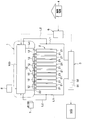
- FIG. 1 is a schematic configuration diagram of a system including a battery temperature control device according to a first embodiment. It is a schematic diagram of a battery cell according to the first embodiment. It is a schematic diagram which shows the electric circuit of the heater of the battery temperature control apparatus which concerns on 1st Embodiment. It is a schematic diagram which shows the upper surface of a part of battery module which concerns on 1st Embodiment.
- FIG. 5 is a sectional view taken along line VV of FIG. 4.
- FIG. 2 is an explanatory diagram for explaining a temperature rise performance of a battery cell in the battery temperature control device according to the first embodiment. It is a schematic structure figure of the system containing the battery temperature control device concerning a 2nd embodiment.
- FIG. 1 It is a schematic diagram which shows the electric circuit of the heater of the battery temperature control apparatus which concerns on 2nd Embodiment. It is a schematic structure figure of the system containing the battery temperature control device concerning a 3rd embodiment. It is a mimetic diagram showing the upper part of a part of battery module concerning a 3rd embodiment. It is XI-XI sectional drawing of FIG. It is a typical sectional view of the battery cell concerning a 4th embodiment. It is a typical perspective view of the insulation heater concerning a 4th embodiment. It is a typical sectional view of the insulation heater concerning a 5th embodiment. It is a schematic diagram which shows the upper surface of a part of battery module which concerns on 6th Embodiment. FIG.
- FIG. 16 is a sectional view taken along the line XVI-XVI in FIG. 15. It is a schematic structure figure of the system containing the battery temperature control device concerning a 7th embodiment. It is a schematic structure figure of the system containing the battery temperature control device which becomes a modification of a 7th embodiment. It is a schematic structure figure of the system containing the battery temperature control device concerning an 8th embodiment.
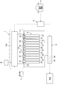
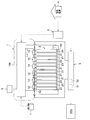
- a vehicle on which the battery temperature control device 1 is mounted for example, an electric vehicle, a hybrid vehicle, and the like, which can be driven by a motor generator MG that uses at least one battery module 2 as a power supply, can be given.
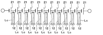
- the battery module 2 is configured by a stacked body in which battery cells 21 having a substantially rectangular parallelepiped shape are stacked.
- Each of the plurality of battery cells 21 is configured by a chargeable / dischargeable secondary battery (for example, a lithium ion battery or a nickel metal hydride battery).
- the plurality of battery cells 21 constituting the battery module 2 are electrically connected to each other. Specifically, one of the pair of electrode terminals included in one battery cell 21 is included in the other battery cell 21 via a bus bar 22 that is a conductive member. Is electrically connected to one of a pair of electrode terminals.
- the plurality of battery cells 21 of the present embodiment are electrically connected in series via a bus bar 22.
- the battery module 2 may have a configuration in which some of the plurality of battery cells 21 are electrically connected in parallel.
- FIG. 1 illustrates the battery module 2 including the twelve battery cells 21, but is not limited thereto.
- the battery module 2 may include 11 or less battery cells 21 or 13 or more battery cells 21.
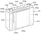
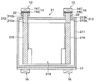
- the details of the battery cell 21 will be described with reference to FIG. In FIG. 2, the internal configuration of the battery cell 21 is indicated by a dotted line to explain the internal configuration of the battery cell 21.
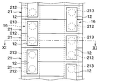
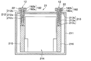
- the battery cell 21 is configured to include a case portion 211 forming an outer shell, a positive terminal 212, and a negative terminal 213.
- the positive electrode terminal 212 and the negative electrode terminal 213 constitute a pair of electrode terminals protruding outside the case portion 211.
- the case portion 211 is an exterior body in which at least a portion exposed to the outside is made of a material having an insulating property.
- An electrolytic solution is injected into the case portion 211, and a stacked electrode body 214, a positive electrode current collector 215, and a negative electrode current collector 216 are housed as power generation elements.
- the electrolytic solution, the laminated electrode body 214, the positive electrode current collector 215, and the negative electrode current collector 216 constitute a housing member housed inside the case portion 211.
- the laminated electrode body 214 has a plurality of separators 214a, a plurality of positive plates 214b, and a plurality of negative plates 214c.
- the laminated electrode body 214 is configured as a laminated body in which positive electrodes 214b and negative electrodes 214c are alternately laminated while being insulated by the separator 214a.
- the plurality of positive electrode plates 214b have respective side ends electrically connected to the positive electrode current collector 215.
- the positive electrode current collector 215 is electrically connected to a portion of the positive electrode terminal 212 located inside the case 211.
- the plurality of negative electrode plates 214c have respective side ends electrically connected to the negative electrode current collector 216.
- the negative electrode current collector 216 is electrically connected to a portion of the negative electrode terminal 213 located inside the case portion 211.
- the positive electrode terminal 212 and the negative electrode terminal 213 are path components that form an external current path together with the bus bar 22 that is a conductive member.
- the positive electrode terminal 212 and the negative electrode terminal 213 are made of a rod-shaped conductive material, a part of which is positioned inside the case part 211, and the remaining part protrudes outward.
- the positive electrode terminal 212 and the negative electrode terminal 213 protrude outward from the same end surface of the case portion 211 at a predetermined interval.
- the positive electrode terminal 212 has a first inside connection portion 212a positioned inside the case portion 211, and a first outside connection portion 212b connected to the first inside connection portion 212a and positioned outside the case portion 211. ing.
- the first inner connection portion 212a and the first outer connection portion 212b are integrally formed of a conductive material.
- the first inner connection portion 212 a has an end located inside the case portion 211 and is electrically connected to the positive electrode current collector 215.
- the first outer connection portion 212 b has an end located outside the case portion 211 connected to the bus bar 22. As a result, the positive electrode terminal 212 is connected to the positive electrode current collector 215 housed inside the case portion 211.
- the negative electrode terminal 213 has a second inside connection portion 213a positioned inside the case portion 211, and a second outside connection portion 213b connected to the second inside connection portion 213a and positioned outside the case portion 211.
- the second inner connection portion 213a and the second outer connection portion 213b are integrally formed of a conductive material.
- the second inner connection portion 213 a has an end located inside the case portion 211 and is electrically connected to the negative electrode current collector 216.
- the second outer connection portion 213b has an end located outside the case portion 211 connected to the bus bar 22.
- the negative electrode terminal 213 is connected to the negative electrode current collector 216 housed inside the case portion 211.
- the battery module 2 is connected to the motor generator MG via the voltage conversion device 3.
- Motor generator MG is configured to be able to transmit power to driving wheels (not shown).
- Motor generator MG serves as a driving power source for the vehicle, and has a power generation function by regenerative drive control.
- the motor generator MG constitutes a target device to which the battery module 2 supplies power.
- the voltage converter 3 includes a boost converter 31 that boosts the output voltage of the battery module 2 up to a predetermined voltage as an upper limit, an inverter 32 that performs DC-AC power conversion, and the like.
- a power conversion device that supplies necessary power to a target device to which the voltage conversion device 3 supplies power is configured.
- the inverter 32 includes a plurality of semiconductor switching elements, and performs power conversion by DC-AC by switching control of the semiconductor switching elements. Inverter 32 converts AC power generated by power generation at the time of power generation by motor generator MG into DC power. Then, the DC power converted by the inverter 32 is charged in the battery module 2. In addition, inverter 32 converts DC power from battery module 2 into AC power when the vehicle is driven by motor generator MG. Then, the AC power converted by inverter 32 is supplied to motor generator MG.
- the vehicle is equipped with a charger 6 for charging the battery module 2 and driving the battery temperature controller 1 by the commercial power supply 4.
- the charger 6 is configured to be connectable to the commercial power supply 4 by a charging cable (not shown). Thereby, the battery module 2 can be charged by the electric power supplied from the commercial power supply 4 via the charger 6.
- the battery temperature control device 1 can be driven by electric power supplied from the commercial power supply 4 via the charger 6.
- the battery temperature control device 1 is a device that adjusts the temperature of the battery module 2 mounted on the vehicle.
- the battery temperature control device 1 includes a temperature control member 10 that controls the temperature of the battery module 2 and a control circuit 100 that controls the temperature of the temperature control member 10.
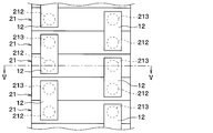
- the temperature control member 10 includes a plurality of temperature control bodies 12 configured to be able to adjust the temperature of the battery cell 21.
- the temperature control member 10 has the same number of temperature control bodies 12 as the bus bars 22 connecting the battery cells 21 to each other. As shown in FIG. 3, the plurality of temperature control bodies 12 are electrically connected in series via a temperature control wiring Lc independent of an external current path in the battery module 2.
- the temperature control member 10 has both ends of the temperature control wiring Lc connected to the control circuit 100 so that power is supplied from the control circuit 100 instead of the external current path in the battery module 2.
- the battery cell 21 composed of the secondary battery has a tendency that the internal resistance increases when the temperature decreases, and the discharge capacity under a low-temperature environment is apt to significantly decrease. Therefore, in a low-temperature environment, it is necessary to warm up the battery module 2 including the battery cells 21.
- the temperature control body 12 is formed of a heating element that generates heat when energized so that the battery cell 21 can be warmed up.
- the temperature control body 12 has at least a part of a path component constituting an external current path such as the positive terminal 212, the negative terminal 213, and the bus bar 22 as a temperature control target, and includes a battery cell including the temperature control target. It is arranged so as to be in thermal contact with 21.
- the temperature controller 12 of the present embodiment is attached to a path component such as the positive electrode terminal 212, the negative electrode terminal 213, and the bus bar 22 with an adhesive having an insulating property.
- the temperature control body 12 may be fixed to the path components such as the positive electrode terminal 212, the negative electrode terminal 213, and the bus bar 22 by a method other than the adhesive.
- the temperature controller 12 includes a heater 14 having a heating resistor 141 that generates heat when energized and an insulator 142 having electrical insulation.
- the heating resistor 141 is formed of a sheet-like conductor that generates Joule heat when energized.
- the insulator 142 is for electrically insulating the heating resistor 141 from the battery cell 21 and is made of a sheet-like insulating material (for example, silicon rubber) having excellent electrical insulation.
- the heating resistor 141 only needs to generate heat when energized, and may be made of, for example, a semiconductor.
- an insulator 142 is arranged between the heating resistor 141 and the battery cell 21 so that the battery cell 21 and the heating resistor 141 are electrically insulated.
- the insulator 142 is disposed between a path component such as the positive terminal 212, the negative terminal 213, and the bus bar 22 and the heating resistor 141.
- the temperature control body 12 is disposed so as to be in thermal contact with the path components such as the positive terminal 212, the negative terminal 213, and the bus bar 22 while being electrically insulated from the battery cell 21. ing.
- the control circuit 100 controls the temperature of the temperature control member 10 by controlling the amount of current supplied to the temperature control member 10.
- the control circuit 100 is configured to control the temperature of the temperature control member 10 using a power supply source other than the battery module 2.
- the control circuit 100 is connected to the auxiliary battery 7 so that the temperature control member 10 can be energized from the auxiliary battery 7 mounted on the vehicle.
- the control circuit 100 is connected to the charger 6 so that the power of the commercial power supply 4 can be used to supply electricity to the temperature control member 10.
- the temperature control body 12 of the temperature control member 10 of the present embodiment is configured to be able to adjust the temperature of the battery cell 21 without using the power of the battery module 2.
- the control circuit 100 is connected to a temperature detecting section 8 for detecting the temperature of the battery module 2.
- the temperature detection unit 8 includes, for example, a single temperature sensor that detects the temperature of a representative portion in the battery module 2 and a plurality of temperature sensors that detect the temperature of each of the battery cells 21.
- the control circuit 100 controls the amount of power to the temperature control member 10 based on the value detected by the temperature detector 8.
- the control circuit 100 is configured to supply power to the temperature control member 10 using the power of the auxiliary battery 7 or the commercial power supply 4 when the temperature of the battery module 2 is lower than a predetermined lower limit temperature, for example. Further, the control circuit 100 is configured to stop the power supply from the auxiliary battery 7 or the commercial power supply 4 to the temperature control member 10 when the temperature of the battery module 2 reaches an appropriate temperature range.
- the control circuit 100 When the temperature of the battery module 2 is lower than the predetermined lower limit temperature, the control circuit 100 energizes the temperature control member 10. At this time, if the power of the commercial power source 4 can be used, the control circuit 100 supplies the power of the commercial power source 4 to the temperature control member 10 via the charger 6. If the power of the commercial power supply 4 cannot be used, the control circuit 100 supplies the power of the auxiliary battery 7 to the temperature control member 10. As a result, the heat generating resistor 141 of the heater 14 generates heat, so that the battery module 2 is warmed up.
- the control circuit 100 stops the power supply from the auxiliary battery 7 or the commercial power supply 4 to the temperature control member 10. Thereby, overheating of the battery module 2 is prevented.
- the above-described battery temperature control device 1 is configured such that the temperature control member 10 includes the temperature control body 12 configured to be able to adjust the temperature of the battery cell 21 without using the power of the battery module 2.
- the temperature control body 12 uses at least a part of the path components such as the positive electrode terminal 212, the negative electrode terminal 213, and the bus bar 22 as a temperature control target, and thermally connects the battery cell 21 including the temperature control target. It is arranged to be in contact.
- the limitation of the input / output of the battery module 2 due to the temperature adjustment of the battery cell 21 by the temperature controller 12 is suppressed. Can be.
- the battery temperature control device 1 uses the positive electrode terminal 212, the negative electrode terminal 213, and the bus bar 22 as temperature control objects of the temperature control body 12. According to this, since the heat of the temperature control body 12 is easily transmitted to the housing member and the electrolytic solution housed inside the case portion 211, the temperature of the battery cell 21 can be adjusted from the inside. As described above, if the temperature of the battery cell 21 can be adjusted from the inside, heat radiation to the outside is suppressed, so that the temperature of the battery cell 21 can be efficiently adjusted.
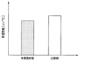
- FIG. 6 is an explanatory diagram for explaining the temperature raising performance of the battery cell 21 by the battery temperature controller 1 of the present embodiment.
- the left side shows the temperature rise performance when the battery temperature controller 1 of the present embodiment is used
- the right side shows the temperature rise performance when the battery temperature controller as a comparative example of the present embodiment is used.
- the performance shown on the left side of FIG. 6 is the temperature-raising performance of the battery cell 21 when the temperature controller 12 is arranged in a path component such as the positive terminal 212, the negative terminal 213, and the bus bar 22.
- the performance shown on the right side of FIG. 6 is the temperature rise performance of the battery cell 21 when the temperature controller 12 is arranged on the bottom surface of the case 211.
- the vertical axis in FIG. 6 indicates the amount of heat required to raise the temperature of the battery cell 21 by 1 ° C. under the same conditions.
- the battery cell 21 is smaller than the case where the temperature controller 12 is arranged on the bottom of the case 211. It can be seen that the temperature rises efficiently.
- the battery temperature control device 1 of the present disclosure it is possible to improve the efficiency of the temperature adjustment of the battery cell 21 while suppressing the restriction on the input and output of power in the battery module 2 due to the temperature adjustment of the battery cell 21. Can be.
- the temperature control body 12 of the present embodiment is constituted by the heater 14 including the heating resistor 141 that generates heat when energized and the insulator 142 having electrical insulation.
- an insulator 142 is arranged between the heating resistor 141 and the temperature control target so that the battery cell 21 and the heating resistor 141 are electrically insulated. According to this, the insulation between the heating resistor 141 and the temperature control target in the battery cell 21 is ensured by the insulator 142. Therefore, the temperature of the battery cell 21 can be appropriately adjusted by energizing the heating resistor 141 while ensuring insulation between the heating resistor 141 and the battery cell 21.
- connection between the plurality of temperature controllers 12 and the control circuit 100 is different from that of the first embodiment.
- portions different from the first embodiment will be mainly described, and description of the same portions as the first embodiment may be omitted.
- a plurality of temperature control bodies 12 are connected to the control circuit 100 via a temperature control wiring Lc independent of an external current path in the battery module 2. ing.
- the plurality of temperature control bodies 12 are individually connected to the control circuit 100 via the temperature control wiring Lc.
- the control circuit 100 is configured to individually adjust the amount of current supplied to the plurality of temperature regulators 12 so that the temperatures of the plurality of temperature regulators 12 can be individually adjusted.
- a temperature detecting section 8A capable of detecting the temperature of each of the battery cells 21 constituting the battery module 2 is connected.
- control circuit 100 is configured to supply current to each of the plurality of temperature regulators 12 when the temperature of each of the plurality of battery cells 21 is lower than a predetermined lower limit temperature, for example. Further, when the temperature of some of the plurality of battery cells 21 is lower than a predetermined lower limit temperature, the control circuit 100 energizes the temperature controller 12 corresponding to the certain number of battery cells 21; The power supply to the temperature controller 12 corresponding to the remaining battery cells 21 is stopped.
- the battery temperature control device 1 of the present embodiment can obtain the same operational effects as those of the first embodiment, which are provided by the same configuration as the first embodiment. This is the same in the following embodiments.
- the battery temperature controller 1 of the present embodiment is capable of individually adjusting the amount of electricity to be supplied to the plurality of temperature controllers 12 so that the temperatures of the plurality of temperature controllers 12 can be individually adjusted. According to this, even when the temperature of the battery cells 21 constituting the battery module 2 varies, the temperature of the battery cells 21 can be adjusted to an appropriate temperature. In addition, since the battery temperature control device 1 does not supply electricity to the battery cells 21 that do not need to perform temperature adjustment, the efficiency of temperature adjustment of the battery cells 21 can be improved.
- the present embodiment is different from the first embodiment in that the temperature control member 10 is configured to include the auxiliary temperature control body 16.
- the present embodiment portions different from the first embodiment will be mainly described, and description of the same portions as the first embodiment may be omitted.
- the temperature control member 10 includes an auxiliary temperature control body 16 configured to be able to adjust the temperature of the battery cell 21 separately from the temperature control body 12.
- the auxiliary temperature controller 16 is configured by a heater capable of securing insulation from the battery cell 21.
- the auxiliary temperature controller 16 is connected to the control circuit 100 so that the temperature of the battery cell 21 can be adjusted without using the power of the battery module 2.
- the control circuit 100 of the present embodiment controls the amount of power to the temperature controller 12 and the auxiliary temperature controller 16 based on the detection value of the temperature detector 8.
- the auxiliary temperature controller 16 is arranged so as to be in thermal contact with a portion of the battery cell 21 that is different from the portion where the temperature controller 12 is disposed, while being electrically insulated from the battery cell 21. I have.
- the auxiliary temperature control body 16 is a part of the battery cell 21 where the positive terminal 212, the negative terminal 213, and the bus bar 22 are provided so that the battery cell 21 is sandwiched between the temperature control body 12 and the auxiliary temperature control body 16. It is located at the site located on the opposite side.
- the auxiliary temperature controller 16 includes a bottom portion of the case portion 211 of the battery cell 21 where the positive terminal 212, the negative terminal 213, and the bus bar 22 are not provided. Are located in
- the soaking plate 17 is arranged between the auxiliary temperature controller 16 and the bottom of the case 211 so that the heat of the auxiliary temperature controller 16 can be easily transmitted to the entire battery cell 21.
- the heat equalizing plate 17 is made of a material having excellent heat conductivity.
- the heat equalizing plate 17 has a size capable of covering the entire bottom surface of the plurality of battery cells 21.
- the battery temperature control device 1 of the present embodiment has a configuration in which the temperature control member 10 includes not only the temperature control body 12 but also an auxiliary temperature control body 16. According to this, since the amount of heat input to the battery cell 21 can be increased, the time required to adjust the battery cell 21 to an appropriate temperature can be shortened. As a result, it is possible to control the temperature of the battery cell 21 with excellent immediate effect while suppressing the limitation of the input / output of the battery module 2 due to the temperature drop of the battery cell 21 or the like.
- the heat equalizing plate 17 is disposed between the auxiliary temperature controller 16 and the bottom of the case 211. According to this, since the heat of the auxiliary temperature regulator 16 is easily transmitted to the entire battery cell 21, it is possible to suppress the occurrence of a temperature distribution in the battery cell 21 when the temperature of the battery cell 21 is adjusted by the auxiliary temperature regulator 16. be able to.
- auxiliary temperature controller 16 is disposed on the bottom surface of the case 211
- the auxiliary temperature controller 16 may be disposed so as to be in thermal contact with a portion of the battery cell 21 different from the portion where the temperature controller 12 is disposed.
- the auxiliary temperature controller 16 may be arranged on a side surface of the case 211.
- the heat equalizing plate 17 be disposed between the auxiliary temperature controller 16 and the bottom surface of the case 211, but the present invention is not limited to this.
- the battery temperature control device 1 may be configured not to include the soaking plate 17.
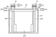
- the present embodiment is different from the first embodiment in that the temperature controller 12 is constituted by an insulating heater 18.
- the present embodiment portions different from the first embodiment will be mainly described, and description of the same portions as the first embodiment may be omitted.
- the temperature controller 12 is constituted by an insulating heater 18 having electrical insulation.
- the insulating heater 18 constituting the temperature control body 12 is disposed so as to contact the positive terminal 212, the negative terminal 213, and the bus bar 22.
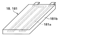
- the insulating heater 18 is composed of a silicon rubber heater 181 in which a heating resistor 181a that generates heat when energized is covered with a silicone rubber 181b.
- the heating resistor 181a is formed of a sheet-like conductor that generates Joule heat when energized.
- the temperature control body 12 includes an insulating heater 18 having electrical insulation. For this reason, the temperature of the battery cell 21 can be appropriately adjusted by the insulating heater 18 while ensuring insulation between the insulating heater 18 and the battery cell 21.
- the insulation heater 18 is constituted by a silicon rubber heater 181.
- the silicon rubber 181b covering the heating resistor 181a functions as an insulating member. Therefore, the temperature of the battery cell 21 can be appropriately adjusted by energizing the heating resistor 181a while ensuring insulation between the heating resistor 181a and the battery cell 21.
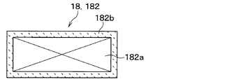
- the present embodiment is different from the fourth embodiment in that the insulating heater 18 is constituted by a ceramic heater 182.
- the insulating heater 18 is constituted by a ceramic heater 182.
- portions different from the fourth embodiment will be mainly described, and description of portions similar to the fourth embodiment may be omitted.
- the insulating heater 18 is composed of a ceramic heater 182 in which a heating resistor 182a that generates heat when energized is covered with a ceramic 182b.
- the heating resistor 182a is formed of a sheet-like conductor that generates Joule heat when energized.
- the insulating heater 18 forming the temperature control body 12 is configured by the ceramic heater 182. According to this, the ceramic 182b covering the heating resistor 182a functions as an insulating member. Therefore, the temperature of the battery cell 21 can be appropriately adjusted by energizing the heating resistor 182a while ensuring insulation between the heating resistor 182a and the battery cell 21.
- the present embodiment is different from the first embodiment in that at least a part of the temperature controller 12 is buried in concave portions 212c and 213c formed in the positive terminal 212 and the negative terminal 213.
- portions different from the first embodiment will be mainly described, and description of the same portions as the first embodiment may be omitted.
- the positive electrode terminal 212 has a first concave portion 212 c that is recessed toward the inside of the case portion 211.
- the first concave portion 212c is formed as a bottomed cylindrical hole extending from the end face of the first outer connecting portion 212b toward the first inner connecting portion 212a. Note that the bottom of the first concave portion 212c is formed in the first inner connection portion 212a.
- the negative electrode terminal 213 has a second concave portion 213c that is depressed toward the inside of the case portion 211.
- the second concave portion 213c is formed of a bottomed cylindrical hole extending from the end face of the second outer connecting portion 213b toward the second inner connecting portion 213a. Note that the bottom of the second recess 213c is formed in the second inner connection portion 213a.
- the temperature controller 12 is constituted by the insulating heater 18 described in the fifth embodiment. That is, the temperature controller 12 is constituted by the ceramic heater 182.
- the temperature control body 12 is entirely buried inside the first concave portion 212c of the positive electrode terminal 212 and the second concave portion 213c of the negative electrode terminal 213.
- the temperature controller 12 is embedded in recesses 212 c and 213 c formed in the positive terminal 212 and the negative terminal 213. According to this, since the temperature control body 12 approaches the housing member and the electrolytic solution housed inside the case portion 211, the heat of the temperature control body 12 is easily transmitted to the housing member and the electrolyte sufficiently, and the temperature control body 12 Heat radiation is suppressed. Therefore, the temperature of the battery cell 21 can be efficiently adjusted.
- the temperature control body 12 is configured by the ceramic heater 182 which is the insulating heater 18 has been described, but the present invention is not limited to this.
- the temperature control body 12 includes the silicon rubber heater 181 described in the fourth embodiment and the heater 14 described in the first embodiment. May be.
- the temperature controller 12 is entirely embedded inside the first concave portion 212c of the positive electrode terminal 212 and the second concave portion 213c of the negative electrode terminal 213.
- the present invention is not limited to this. At least a part of the temperature control body 12 may be embedded inside the first concave portion 212c of the positive terminal 212 and the second concave portion 213c of the negative terminal 213.
- the battery temperature controller 1 has a configuration in which a concave portion is formed in one of the positive electrode terminal 212 and the negative electrode terminal 213 of the battery cell 21 and the temperature controller 12 is embedded in the concave portion of the electrode terminal. Is also good.
- a seventh embodiment will be described with reference to FIG.
- the present embodiment is different from the first embodiment in that a plurality of temperature regulators 12 operate using electric power from the battery module 2.
- portions different from the first embodiment will be mainly described, and description of the same portions as the first embodiment may be omitted.
- the control circuit 100 of the present embodiment is configured to control the temperature of the temperature control member 10. As shown in FIG. 17, the control circuit 100 is connected to the battery module 2 so that the battery module 2 can supply electricity to the temperature control member 10. Specifically, the control circuit 100 is connected to the battery module 2 via a branch line L2 branched from a connection line L1 connecting the voltage conversion device 3 and the battery module 2. Control circuit 100 is electrically connected in parallel to voltage conversion device 3 that controls the power to motor generator MG so that the power of battery module 2 can be supplied independently of the power supplied to motor generator MG. It is connected.
- the plurality of temperature control bodies 12 are connected to the control circuit 100 via the temperature control wiring Lc.
- the power of the battery module 2 is supplied to the plurality of temperature controllers 12 via the control circuit 100.
- the control circuit 100 of the present embodiment is configured to be able to supply the power of the battery module 2 to the temperature control member 10 independently of the power supplied to the motor generator MG.
- the plurality of temperature controllers 12 are connected to the control circuit 100 such that the power of the battery module 2 is supplied independently of the power supplied to the motor generator MG. .
- the motor generator MG and the plurality of temperature controllers 12 constitute a target device to which the battery module 2 supplies power.
- the voltage conversion device 3 and the control circuit 100 constitute a power conversion device that supplies necessary power to a plurality of target devices to be supplied with power.
- the battery temperature controller 1 of the present embodiment is configured such that the plurality of temperature controllers 12 can supply the power of the battery module 2 independently of the power supplied to the motor generator MG. According to this, the limitation of the output from the battery module 2 to the motor generator MG due to the temperature adjustment of the battery cells 21 by the plurality of temperature regulators 12 can be suppressed. That is, the temperature of the battery cell 21 can be appropriately adjusted by the temperature controller 12 irrespective of the discharge state of the battery module 2 to other target devices.
- the battery temperature control device 1 uses the positive electrode terminal 212, the negative electrode terminal 213, and the bus bar 22 as temperature control objects of the temperature control body 12. According to this, since the heat of the temperature control body 12 is easily transmitted to the housing member and the electrolytic solution housed inside the case portion 211, the temperature of the battery cell 21 can be adjusted from the inside. As described above, if the temperature of the battery cell 21 can be adjusted from the inside, heat radiation to the outside is suppressed, so that the temperature of the battery cell 21 can be efficiently adjusted.
- the present embodiment is different from the seventh embodiment in that the temperature control member 10 is configured to include an auxiliary temperature control body 16.
- the present embodiment parts different from the seventh embodiment will be mainly described, and description of the same parts as the seventh embodiment may be omitted.
- the temperature control member 10 includes an auxiliary temperature control body 16 configured to adjust the temperature of the battery cell 21 separately from the temperature control body 12.
- the auxiliary temperature controller 16 is configured by a heater capable of securing insulation from the battery cell 21.
- the auxiliary temperature controller 16 is connected to the control circuit 100 so that the power of the battery module 2 is supplied independently of the power supplied to the motor generator MG.
- the control circuit 100 of the present embodiment controls the amount of power to the temperature control body 12 and the auxiliary temperature control body 16 based on the value detected by the temperature detection unit 8.
- the auxiliary temperature controller 16 has the same configuration as that described in the third embodiment. In the present embodiment, the description of the details of the auxiliary temperature controller 16 is omitted.
- the battery temperature control device 1 of the present embodiment has a configuration in which the temperature control member 10 includes not only the temperature control body 12 but also an auxiliary temperature control body 16. According to this, since the amount of heat input to the battery cell 21 can be increased, the time required to adjust the battery cell 21 to an appropriate temperature can be shortened.
- the temperature controller 12 and the auxiliary temperature controller 16 are configured to be supplied with the power of the battery module 2 independently of the power supplied to the motor generator MG.
- the limitation of the output from battery module 2 to motor generator MG due to the temperature adjustment of battery cell 21 by temperature controller 12 and auxiliary temperature controller 16 is suppressed. That is, the temperature of the battery cell 21 can be appropriately adjusted by the temperature controller 12 and the auxiliary temperature controller 16 irrespective of the state of discharge to other target devices in the battery module 2.
- the temperature control member 10 has the same number of the temperature control bodies 12 as the bus bars 22 connecting the battery cells 21 to each other, but is not limited thereto.
- the temperature control member 10 may have, for example, a configuration including a smaller number of temperature control bodies 12 than the bus bar 22.
- the temperature control body 12 is configured by a heating element that generates heat when energized, but the present invention is not limited to this.
- the temperature control body 12 may be configured by, for example, a heat medium circulating unit such as a high-temperature pipe through which a high-temperature heat medium flows.
- the temperature control body 12 may be configured by a heat absorber whose one surface side becomes low temperature by energization, such as a Peltier module, for example.
- the temperature control body 12 may be configured by a refrigerant distribution unit such as a low-temperature pipe through which a low-temperature refrigerant flows.
- the battery temperature control device 1 of the present disclosure is applied to a device that adjusts the temperature of the battery module 2 mounted on a vehicle, but is not limited thereto.
- the battery temperature controller 1 is also applicable to, for example, a device that adjusts the temperature of a battery module 2 installed in a house or a factory.
- the battery temperature control device includes a temperature control member that controls the temperature of the battery module.
- the temperature control member includes a temperature control body configured to be able to adjust the temperature of the battery cell without using the power of the battery module.
- the temperature control body has at least a part of a path component constituting an external current path such as a pair of electrode terminals and a conductive member as a temperature control target, and is electrically insulated from a battery cell including the temperature control target. It is arranged so as to be in thermal contact with the temperature control target in the state.
- the temperature control member of the battery temperature control device includes an auxiliary temperature control body configured to be able to adjust the temperature of the battery cell without using the power of the battery module, separately from the temperature control body. Contains. Then, the auxiliary temperature controller is in a state of being electrically insulated from the battery cell including the temperature control target, and thermally contacting a portion of the battery cell different from the portion where the temperature controller is disposed. Are located in
- the battery cell is adjusted to an appropriate temperature.
- the time until the time can be shortened. Accordingly, it is possible to control the temperature of the battery cell excellent in immediate effect while suppressing the limitation of the input and output of the battery module due to the temperature drop of the battery cell and the like.
- the battery temperature control device includes a temperature control member that controls the temperature of the battery module.
- the temperature control member includes a temperature control body configured to adjust the temperature of the battery cell.
- the temperature controller is included in the target device and is connected to the power converter so that the power of the battery module is supplied independently of the power supplied to other target devices.
- the temperature control body has at least a part of a path constituting part constituting an external current path such as a pair of electrode terminals and a conductive member as a temperature control target, and is electrically insulated from a battery cell including the temperature control target. It is arranged so as to be in thermal contact with the temperature control target in the state in which the temperature control is performed.
- the temperature control member of the battery temperature control device includes, apart from the temperature control element, an auxiliary temperature control element configured to adjust the temperature of the battery cell.
- the auxiliary temperature controller is included in the target device and is connected to the power converter so that the power of the battery module is supplied independently of the power supplied to other target devices.
- the auxiliary temperature control body is configured to be in thermal contact with a part of the battery cell that is different from the part where the temperature control body is arranged, while being electrically insulated from the battery cell including the temperature control target. Are located in
- the temperature control body of the battery temperature control device is constituted by a heater including a heating resistor that generates heat when energized and an insulator having electrical insulation.
- a heater including a heating resistor that generates heat when energized and an insulator having electrical insulation.
- an insulator is arranged between the heating resistor and the temperature control target so that the battery cell and the heating resistor are electrically insulated. According to this, since the insulation between the heating resistor and the battery cell is ensured by the insulator, the temperature of the battery cell is controlled by energizing the heating resistor while ensuring the insulation between the heating resistor and the battery cell. Can be adjusted appropriately.
- the temperature controller of the battery temperature controller is constituted by an insulating heater having electrical insulation. And the insulation heater is arrange
- the insulating heater of the battery temperature control device is constituted by a silicon rubber heater in which a heating resistor that generates heat when energized is covered with silicon rubber. If a silicon rubber heater is adopted as the insulating heater, the silicon rubber covering the heating resistor functions as an insulating member. Therefore, it is possible to appropriately adjust the temperature of the battery cell by energizing the heating resistor while ensuring insulation between the heating resistor and the battery cell.
- the insulation heater of the battery temperature control device is constituted by a ceramic heater in which a heating resistor that generates heat when energized is covered with ceramics. If a ceramic heater is used as the insulating heater, the ceramic covering the heating resistor functions as an insulating member. Therefore, it is possible to appropriately adjust the temperature of the battery cell by energizing the heating resistor while ensuring insulation between the heating resistor and the battery cell.
- At least one of the pair of electrode terminal portions has a concave portion that is recessed toward the inside of the case portion.
- the temperature control body is at least partially embedded in the recess.
- the temperature control body approaches the housing member housed inside the case portion, the heat of the temperature control body is easily transmitted sufficiently to the housing member, and the heat radiation to the outside is suppressed. Therefore, the temperature adjustment of the battery cells can be efficiently performed.
Landscapes
- Engineering & Computer Science (AREA)
- Manufacturing & Machinery (AREA)
- Chemical & Material Sciences (AREA)
- Chemical Kinetics & Catalysis (AREA)
- Electrochemistry (AREA)
- General Chemical & Material Sciences (AREA)
- Secondary Cells (AREA)
- Physics & Mathematics (AREA)
- Electromagnetism (AREA)
Applications Claiming Priority (2)
| Application Number | Priority Date | Filing Date | Title |
|---|---|---|---|
| JP2018120963A JP2020004532A (ja) | 2018-06-26 | 2018-06-26 | 電池温調装置 |
| JP2018-120963 | 2018-06-26 |
Publications (1)
| Publication Number | Publication Date |
|---|---|
| WO2020004313A1 true WO2020004313A1 (ja) | 2020-01-02 |
Family
ID=68987034
Family Applications (1)
| Application Number | Title | Priority Date | Filing Date |
|---|---|---|---|
| PCT/JP2019/024924 Ceased WO2020004313A1 (ja) | 2018-06-26 | 2019-06-24 | 電池温調装置 |
Country Status (2)
| Country | Link |
|---|---|
| JP (1) | JP2020004532A (enExample) |
| WO (1) | WO2020004313A1 (enExample) |
Cited By (1)
| Publication number | Priority date | Publication date | Assignee | Title |
|---|---|---|---|---|
| CN119447602A (zh) * | 2024-11-28 | 2025-02-14 | 孝感楚能新能源创新科技有限公司 | 动力电池均温系统的控制方法、装置、设备和介质 |
Families Citing this family (2)
| Publication number | Priority date | Publication date | Assignee | Title |
|---|---|---|---|---|
| KR102848341B1 (ko) * | 2020-07-28 | 2025-08-19 | 주식회사 엘지에너지솔루션 | 이차전지용 충방전 장치 |
| JP7672312B2 (ja) * | 2021-09-01 | 2025-05-07 | 本田技研工業株式会社 | 昇温システム |
Citations (12)
| Publication number | Priority date | Publication date | Assignee | Title |
|---|---|---|---|---|
| JPH11162507A (ja) * | 1994-09-08 | 1999-06-18 | Ngk Insulators Ltd | ナトリウム−硫黄電池よりなる集合電池の加熱装置及びそれを備えた集合電池並びに加熱方法 |
| JPH11354166A (ja) * | 1998-06-08 | 1999-12-24 | Sony Tektronix Corp | バッテリ温度制御装置 |
| JP2003068354A (ja) * | 2001-08-27 | 2003-03-07 | Hitachi Ltd | ナトリウム二次電池 |
| JP2004018345A (ja) * | 2002-06-19 | 2004-01-22 | Jigyo Sozo Kenkyusho:Kk | 炭化水素、含酸素化合物を原料とする水素の生成装置 |
| WO2008156167A1 (ja) * | 2007-06-21 | 2008-12-24 | Toyota Jidosha Kabushiki Kaisha | 蓄電装置及び車両 |
| WO2011001691A1 (ja) * | 2009-07-03 | 2011-01-06 | パナソニック株式会社 | 加熱装置及び加熱装置を備えるバッテリユニット |
| JP2012094330A (ja) * | 2010-10-26 | 2012-05-17 | Sony Corp | 電池ユニット |
| JP2012174662A (ja) * | 2011-02-24 | 2012-09-10 | Sumitomo Electric Ind Ltd | 溶融塩電池装置、溶融塩電池システム、及び溶融塩電池装置の制御方法 |
| JP2013254637A (ja) * | 2012-06-07 | 2013-12-19 | Panasonic Corp | 組電池 |
| WO2015041134A1 (ja) * | 2013-09-19 | 2015-03-26 | 日本碍子株式会社 | 集合電池用容器 |
| JP2015156765A (ja) * | 2014-02-21 | 2015-08-27 | 三菱重工業株式会社 | 電動車両、および電動車両のバッテリ加温方法 |
| JP2017022817A (ja) * | 2015-07-08 | 2017-01-26 | トヨタ自動車株式会社 | バッテリの充電制御装置 |
Family Cites Families (1)
| Publication number | Priority date | Publication date | Assignee | Title |
|---|---|---|---|---|
| JP2009266413A (ja) * | 2008-04-22 | 2009-11-12 | Toyota Motor Corp | 組電池 |
-
2018
- 2018-06-26 JP JP2018120963A patent/JP2020004532A/ja active Pending
-
2019
- 2019-06-24 WO PCT/JP2019/024924 patent/WO2020004313A1/ja not_active Ceased
Patent Citations (12)
| Publication number | Priority date | Publication date | Assignee | Title |
|---|---|---|---|---|
| JPH11162507A (ja) * | 1994-09-08 | 1999-06-18 | Ngk Insulators Ltd | ナトリウム−硫黄電池よりなる集合電池の加熱装置及びそれを備えた集合電池並びに加熱方法 |
| JPH11354166A (ja) * | 1998-06-08 | 1999-12-24 | Sony Tektronix Corp | バッテリ温度制御装置 |
| JP2003068354A (ja) * | 2001-08-27 | 2003-03-07 | Hitachi Ltd | ナトリウム二次電池 |
| JP2004018345A (ja) * | 2002-06-19 | 2004-01-22 | Jigyo Sozo Kenkyusho:Kk | 炭化水素、含酸素化合物を原料とする水素の生成装置 |
| WO2008156167A1 (ja) * | 2007-06-21 | 2008-12-24 | Toyota Jidosha Kabushiki Kaisha | 蓄電装置及び車両 |
| WO2011001691A1 (ja) * | 2009-07-03 | 2011-01-06 | パナソニック株式会社 | 加熱装置及び加熱装置を備えるバッテリユニット |
| JP2012094330A (ja) * | 2010-10-26 | 2012-05-17 | Sony Corp | 電池ユニット |
| JP2012174662A (ja) * | 2011-02-24 | 2012-09-10 | Sumitomo Electric Ind Ltd | 溶融塩電池装置、溶融塩電池システム、及び溶融塩電池装置の制御方法 |
| JP2013254637A (ja) * | 2012-06-07 | 2013-12-19 | Panasonic Corp | 組電池 |
| WO2015041134A1 (ja) * | 2013-09-19 | 2015-03-26 | 日本碍子株式会社 | 集合電池用容器 |
| JP2015156765A (ja) * | 2014-02-21 | 2015-08-27 | 三菱重工業株式会社 | 電動車両、および電動車両のバッテリ加温方法 |
| JP2017022817A (ja) * | 2015-07-08 | 2017-01-26 | トヨタ自動車株式会社 | バッテリの充電制御装置 |
Cited By (1)
| Publication number | Priority date | Publication date | Assignee | Title |
|---|---|---|---|---|
| CN119447602A (zh) * | 2024-11-28 | 2025-02-14 | 孝感楚能新能源创新科技有限公司 | 动力电池均温系统的控制方法、装置、设备和介质 |
Also Published As
| Publication number | Publication date |
|---|---|
| JP2020004532A (ja) | 2020-01-09 |
Similar Documents
| Publication | Publication Date | Title |
|---|---|---|
| CN100495809C (zh) | 二次电池模块 | |
| JP5752151B2 (ja) | 電池の内部抵抗を使用して動作性能を改善するための電池パックシステム | |
| CN111788709B (zh) | 电池机械和热力系统及制造方法、电池模块、模块化电池 | |
| JP3809549B2 (ja) | 電源装置と分散型電源システムおよびこれを搭載した電気自動車 | |
| CN102870272B (zh) | 电池包 | |
| CN105591048B (zh) | 用于袋式电池单元的牵引电池汇流条支架 | |
| JP2012234749A (ja) | 電池の温度調節システム | |
| US9484562B2 (en) | Traction battery assembly | |
| US20130183565A1 (en) | Casing for an electrochemical cell | |
| US20150325893A1 (en) | Heat retaining vehicle battery assembly | |
| JP2013539175A (ja) | バッテリー・モジュールとこれを含むバッテリーパック | |
| WO2013042165A1 (ja) | 車両用バッテリの制御装置及び車両用バッテリの制御方法 | |
| JP2013525945A (ja) | バッテリーモジュール用電圧検出アセンブリ及びこれを採用したバッテリーモジュール | |
| CN114144921B (zh) | 电池模块、包括该电池模块的电池组和包括该电池组的车辆 | |
| CN102005624A (zh) | 用于加热蓄电池的方法、充电器以及附加元件 | |
| JP5077163B2 (ja) | 蓄電装置 | |
| WO2020004313A1 (ja) | 電池温調装置 | |
| JP2010097923A (ja) | 蓄電装置及び車両 | |
| WO2021065160A1 (ja) | 電池モジュールとこの電池モジュールを備える電動車両及び蓄電装置 | |
| US11600874B2 (en) | Electrical equipment battery for vehicles | |
| US20160111760A1 (en) | Power storage module | |
| KR20130009698A (ko) | 배터리 온도 조절 시스템 및 이의 구동 방법 | |
| WO2020022087A1 (ja) | 電池温調装置 | |
| US20140146588A1 (en) | Capacitance element housing unit | |
| CN103081179A (zh) | 具有集成式电池连接器的高压电池组 |
Legal Events
| Date | Code | Title | Description |
|---|---|---|---|
| 121 | Ep: the epo has been informed by wipo that ep was designated in this application |
Ref document number: 19825390 Country of ref document: EP Kind code of ref document: A1 |
|
| NENP | Non-entry into the national phase |
Ref country code: DE |
|
| 122 | Ep: pct application non-entry in european phase |
Ref document number: 19825390 Country of ref document: EP Kind code of ref document: A1 |