WO2020004313A1 - Battery temperature adjustment device - Google Patents
Battery temperature adjustment device Download PDFInfo
- Publication number
- WO2020004313A1 WO2020004313A1 PCT/JP2019/024924 JP2019024924W WO2020004313A1 WO 2020004313 A1 WO2020004313 A1 WO 2020004313A1 JP 2019024924 W JP2019024924 W JP 2019024924W WO 2020004313 A1 WO2020004313 A1 WO 2020004313A1
- Authority
- WO
- WIPO (PCT)
- Prior art keywords
- temperature control
- battery
- temperature
- battery cell
- power
- Prior art date
Links
Images


Classifications
-
- H—ELECTRICITY
- H01—ELECTRIC ELEMENTS
- H01M—PROCESSES OR MEANS, e.g. BATTERIES, FOR THE DIRECT CONVERSION OF CHEMICAL ENERGY INTO ELECTRICAL ENERGY
- H01M10/00—Secondary cells; Manufacture thereof
- H01M10/60—Heating or cooling; Temperature control
- H01M10/61—Types of temperature control
- H01M10/615—Heating or keeping warm
-
- H—ELECTRICITY
- H01—ELECTRIC ELEMENTS
- H01M—PROCESSES OR MEANS, e.g. BATTERIES, FOR THE DIRECT CONVERSION OF CHEMICAL ENERGY INTO ELECTRICAL ENERGY
- H01M10/00—Secondary cells; Manufacture thereof
- H01M10/60—Heating or cooling; Temperature control
- H01M10/62—Heating or cooling; Temperature control specially adapted for specific applications
- H01M10/625—Vehicles
-
- H—ELECTRICITY
- H01—ELECTRIC ELEMENTS
- H01M—PROCESSES OR MEANS, e.g. BATTERIES, FOR THE DIRECT CONVERSION OF CHEMICAL ENERGY INTO ELECTRICAL ENERGY
- H01M10/00—Secondary cells; Manufacture thereof
- H01M10/60—Heating or cooling; Temperature control
- H01M10/64—Heating or cooling; Temperature control characterised by the shape of the cells
- H01M10/647—Prismatic or flat cells, e.g. pouch cells
-
- H—ELECTRICITY
- H01—ELECTRIC ELEMENTS
- H01M—PROCESSES OR MEANS, e.g. BATTERIES, FOR THE DIRECT CONVERSION OF CHEMICAL ENERGY INTO ELECTRICAL ENERGY
- H01M10/00—Secondary cells; Manufacture thereof
- H01M10/60—Heating or cooling; Temperature control
- H01M10/65—Means for temperature control structurally associated with the cells
- H01M10/654—Means for temperature control structurally associated with the cells located inside the innermost case of the cells, e.g. mandrels, electrodes or electrolytes
-
- H—ELECTRICITY
- H01—ELECTRIC ELEMENTS
- H01M—PROCESSES OR MEANS, e.g. BATTERIES, FOR THE DIRECT CONVERSION OF CHEMICAL ENERGY INTO ELECTRICAL ENERGY
- H01M10/00—Secondary cells; Manufacture thereof
- H01M10/60—Heating or cooling; Temperature control
- H01M10/65—Means for temperature control structurally associated with the cells
- H01M10/657—Means for temperature control structurally associated with the cells by electric or electromagnetic means
- H01M10/6571—Resistive heaters
-
- Y—GENERAL TAGGING OF NEW TECHNOLOGICAL DEVELOPMENTS; GENERAL TAGGING OF CROSS-SECTIONAL TECHNOLOGIES SPANNING OVER SEVERAL SECTIONS OF THE IPC; TECHNICAL SUBJECTS COVERED BY FORMER USPC CROSS-REFERENCE ART COLLECTIONS [XRACs] AND DIGESTS
- Y02—TECHNOLOGIES OR APPLICATIONS FOR MITIGATION OR ADAPTATION AGAINST CLIMATE CHANGE
- Y02E—REDUCTION OF GREENHOUSE GAS [GHG] EMISSIONS, RELATED TO ENERGY GENERATION, TRANSMISSION OR DISTRIBUTION
- Y02E60/00—Enabling technologies; Technologies with a potential or indirect contribution to GHG emissions mitigation
- Y02E60/10—Energy storage using batteries
Definitions
- the present disclosure relates to a battery temperature control device applied to at least one battery module in which a plurality of chargeable / dischargeable battery cells are electrically connected via a conductive member.
- a resistor is provided in a current path through which a large current flows in a battery module to which a plurality of battery cells are electrically connected. Specifically, the resistor is electrically connected in series to each of the battery cells. For this reason, for example, under conditions in which the electrical resistance of the resistor increases, the input / output of power in the battery module is greatly restricted.
- An object of the present disclosure is to improve the efficiency of temperature adjustment of a battery cell while suppressing the restriction on input and output of power in a battery module due to the temperature adjustment of a battery cell.
- the present disclosure is directed to a battery temperature controller applied to at least one battery module in which a plurality of chargeable / dischargeable battery cells are electrically connected via a conductive member.
- a battery temperature control device includes a temperature control member that controls the temperature of a battery module.
- Each of the plurality of battery cells has a case part forming an outer shell, a housing member housed inside the case part, and a pair of electrode terminals protruding outside the case part and connected to the housing member. .
- One of a pair of electrode terminals included in one of the battery cells is electrically connected to one of a pair of electrode terminals included in the other battery cell via a conductive member.
- the temperature control member includes a temperature control body configured to be able to adjust the temperature of the battery cell without using the power of the battery module.
- the temperature control body has at least a part of a path component constituting an external current path such as a pair of electrode terminals and a conductive member as a temperature control target, and is electrically insulated from a battery cell including the temperature control target. It is arranged so as to be in thermal contact with the temperature control target in the state in which the temperature control is performed.
- the limitation of the input / output of the battery module due to the temperature adjustment of the battery cell by the temperature controller can be suppressed. That is, the temperature of the battery cell by the temperature controller can be appropriately adjusted regardless of the charge / discharge state of the battery module.
- the pair of electrode terminals are connected to a housing member housed inside the case portion.
- the conductive member is connected to the housing member via one of the pair of electrode terminals.
- a battery temperature control device includes a temperature control member that controls a temperature of a battery module.
- the battery module is connected to the power converter so that necessary power can be supplied to a target device to be supplied with power.
- Each of the plurality of battery cells has a case part forming an outer shell, a housing member housed inside the case part, and a pair of electrode terminals protruding outside the case part and connected to the housing member. .
- One of a pair of electrode terminals included in one of the battery cells is electrically connected to one of a pair of electrode terminals included in the other battery cell via a conductive member.
- the temperature control member includes a temperature control body configured to adjust the temperature of the battery cell.
- the temperature controller is connected to the power converter so that the power of the battery module is supplied independently of the power supplied to the target device. Further, the temperature control body has at least a part of a path constituting part constituting an external current path such as a pair of electrode terminals and a conductive member as a temperature control target, and is electrically insulated from a battery cell including the temperature control target. It is arranged so as to be in thermal contact with the temperature control target in the state in which the temperature control is performed.
- the temperature controller since the temperature controller is configured to be able to supply the power of the battery module independently of the power supplied to the other target devices, the temperature controller controls the temperature of the battery cells by the temperature controller. Restrictions on output to other target devices can be suppressed. That is, the temperature of the battery cell can be appropriately adjusted by the temperature controller regardless of the discharge state of the battery module to another target device.
- the temperature of the battery cells can be adjusted from the inside. As described above, if the temperature of the battery cell can be adjusted from the inside, the heat radiation to the outside is suppressed, so that the temperature of the battery cell can be efficiently adjusted.
- the battery temperature control device of the present disclosure it is possible to improve the efficiency of the temperature adjustment of the battery cell while suppressing the restriction on the input and output of power in the battery module due to the temperature adjustment of the battery cell.
- thermal contact means not only a state in which the members are in direct contact with each other, but also a case in which another element such as an air layer is interposed between the members. And a state in which heat is indirectly transferred between members via the interface.
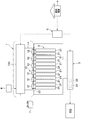
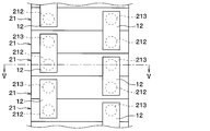
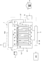
- FIG. 1 is a schematic configuration diagram of a system including a battery temperature control device according to a first embodiment. It is a schematic diagram of a battery cell according to the first embodiment. It is a schematic diagram which shows the electric circuit of the heater of the battery temperature control apparatus which concerns on 1st Embodiment. It is a schematic diagram which shows the upper surface of a part of battery module which concerns on 1st Embodiment.
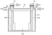
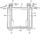
- FIG. 5 is a sectional view taken along line VV of FIG. 4.
- FIG. 2 is an explanatory diagram for explaining a temperature rise performance of a battery cell in the battery temperature control device according to the first embodiment. It is a schematic structure figure of the system containing the battery temperature control device concerning a 2nd embodiment.
- FIG. 1 It is a schematic diagram which shows the electric circuit of the heater of the battery temperature control apparatus which concerns on 2nd Embodiment. It is a schematic structure figure of the system containing the battery temperature control device concerning a 3rd embodiment. It is a mimetic diagram showing the upper part of a part of battery module concerning a 3rd embodiment. It is XI-XI sectional drawing of FIG. It is a typical sectional view of the battery cell concerning a 4th embodiment. It is a typical perspective view of the insulation heater concerning a 4th embodiment. It is a typical sectional view of the insulation heater concerning a 5th embodiment. It is a schematic diagram which shows the upper surface of a part of battery module which concerns on 6th Embodiment. FIG.
- FIG. 16 is a sectional view taken along the line XVI-XVI in FIG. 15. It is a schematic structure figure of the system containing the battery temperature control device concerning a 7th embodiment. It is a schematic structure figure of the system containing the battery temperature control device which becomes a modification of a 7th embodiment. It is a schematic structure figure of the system containing the battery temperature control device concerning an 8th embodiment.
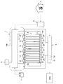
- a vehicle on which the battery temperature control device 1 is mounted for example, an electric vehicle, a hybrid vehicle, and the like, which can be driven by a motor generator MG that uses at least one battery module 2 as a power supply, can be given.
- the battery module 2 is configured by a stacked body in which battery cells 21 having a substantially rectangular parallelepiped shape are stacked.
- Each of the plurality of battery cells 21 is configured by a chargeable / dischargeable secondary battery (for example, a lithium ion battery or a nickel metal hydride battery).
- the plurality of battery cells 21 constituting the battery module 2 are electrically connected to each other. Specifically, one of the pair of electrode terminals included in one battery cell 21 is included in the other battery cell 21 via a bus bar 22 that is a conductive member. Is electrically connected to one of a pair of electrode terminals.
- the plurality of battery cells 21 of the present embodiment are electrically connected in series via a bus bar 22.
- the battery module 2 may have a configuration in which some of the plurality of battery cells 21 are electrically connected in parallel.
- FIG. 1 illustrates the battery module 2 including the twelve battery cells 21, but is not limited thereto.
- the battery module 2 may include 11 or less battery cells 21 or 13 or more battery cells 21.
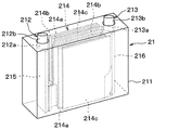
- the details of the battery cell 21 will be described with reference to FIG. In FIG. 2, the internal configuration of the battery cell 21 is indicated by a dotted line to explain the internal configuration of the battery cell 21.
- the battery cell 21 is configured to include a case portion 211 forming an outer shell, a positive terminal 212, and a negative terminal 213.
- the positive electrode terminal 212 and the negative electrode terminal 213 constitute a pair of electrode terminals protruding outside the case portion 211.
- the case portion 211 is an exterior body in which at least a portion exposed to the outside is made of a material having an insulating property.
- An electrolytic solution is injected into the case portion 211, and a stacked electrode body 214, a positive electrode current collector 215, and a negative electrode current collector 216 are housed as power generation elements.
- the electrolytic solution, the laminated electrode body 214, the positive electrode current collector 215, and the negative electrode current collector 216 constitute a housing member housed inside the case portion 211.
- the laminated electrode body 214 has a plurality of separators 214a, a plurality of positive plates 214b, and a plurality of negative plates 214c.
- the laminated electrode body 214 is configured as a laminated body in which positive electrodes 214b and negative electrodes 214c are alternately laminated while being insulated by the separator 214a.
- the plurality of positive electrode plates 214b have respective side ends electrically connected to the positive electrode current collector 215.
- the positive electrode current collector 215 is electrically connected to a portion of the positive electrode terminal 212 located inside the case 211.
- the plurality of negative electrode plates 214c have respective side ends electrically connected to the negative electrode current collector 216.
- the negative electrode current collector 216 is electrically connected to a portion of the negative electrode terminal 213 located inside the case portion 211.
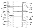
- the positive electrode terminal 212 and the negative electrode terminal 213 are path components that form an external current path together with the bus bar 22 that is a conductive member.
- the positive electrode terminal 212 and the negative electrode terminal 213 are made of a rod-shaped conductive material, a part of which is positioned inside the case part 211, and the remaining part protrudes outward.
- the positive electrode terminal 212 and the negative electrode terminal 213 protrude outward from the same end surface of the case portion 211 at a predetermined interval.
- the positive electrode terminal 212 has a first inside connection portion 212a positioned inside the case portion 211, and a first outside connection portion 212b connected to the first inside connection portion 212a and positioned outside the case portion 211. ing.
- the first inner connection portion 212a and the first outer connection portion 212b are integrally formed of a conductive material.
- the first inner connection portion 212 a has an end located inside the case portion 211 and is electrically connected to the positive electrode current collector 215.
- the first outer connection portion 212 b has an end located outside the case portion 211 connected to the bus bar 22. As a result, the positive electrode terminal 212 is connected to the positive electrode current collector 215 housed inside the case portion 211.
- the negative electrode terminal 213 has a second inside connection portion 213a positioned inside the case portion 211, and a second outside connection portion 213b connected to the second inside connection portion 213a and positioned outside the case portion 211.
- the second inner connection portion 213a and the second outer connection portion 213b are integrally formed of a conductive material.
- the second inner connection portion 213 a has an end located inside the case portion 211 and is electrically connected to the negative electrode current collector 216.
- the second outer connection portion 213b has an end located outside the case portion 211 connected to the bus bar 22.
- the negative electrode terminal 213 is connected to the negative electrode current collector 216 housed inside the case portion 211.
- the battery module 2 is connected to the motor generator MG via the voltage conversion device 3.
- Motor generator MG is configured to be able to transmit power to driving wheels (not shown).
- Motor generator MG serves as a driving power source for the vehicle, and has a power generation function by regenerative drive control.
- the motor generator MG constitutes a target device to which the battery module 2 supplies power.
- the voltage converter 3 includes a boost converter 31 that boosts the output voltage of the battery module 2 up to a predetermined voltage as an upper limit, an inverter 32 that performs DC-AC power conversion, and the like.
- a power conversion device that supplies necessary power to a target device to which the voltage conversion device 3 supplies power is configured.
- the inverter 32 includes a plurality of semiconductor switching elements, and performs power conversion by DC-AC by switching control of the semiconductor switching elements. Inverter 32 converts AC power generated by power generation at the time of power generation by motor generator MG into DC power. Then, the DC power converted by the inverter 32 is charged in the battery module 2. In addition, inverter 32 converts DC power from battery module 2 into AC power when the vehicle is driven by motor generator MG. Then, the AC power converted by inverter 32 is supplied to motor generator MG.
- the vehicle is equipped with a charger 6 for charging the battery module 2 and driving the battery temperature controller 1 by the commercial power supply 4.
- the charger 6 is configured to be connectable to the commercial power supply 4 by a charging cable (not shown). Thereby, the battery module 2 can be charged by the electric power supplied from the commercial power supply 4 via the charger 6.
- the battery temperature control device 1 can be driven by electric power supplied from the commercial power supply 4 via the charger 6.
- the battery temperature control device 1 is a device that adjusts the temperature of the battery module 2 mounted on the vehicle.
- the battery temperature control device 1 includes a temperature control member 10 that controls the temperature of the battery module 2 and a control circuit 100 that controls the temperature of the temperature control member 10.
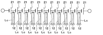
- the temperature control member 10 includes a plurality of temperature control bodies 12 configured to be able to adjust the temperature of the battery cell 21.
- the temperature control member 10 has the same number of temperature control bodies 12 as the bus bars 22 connecting the battery cells 21 to each other. As shown in FIG. 3, the plurality of temperature control bodies 12 are electrically connected in series via a temperature control wiring Lc independent of an external current path in the battery module 2.
- the temperature control member 10 has both ends of the temperature control wiring Lc connected to the control circuit 100 so that power is supplied from the control circuit 100 instead of the external current path in the battery module 2.
- the battery cell 21 composed of the secondary battery has a tendency that the internal resistance increases when the temperature decreases, and the discharge capacity under a low-temperature environment is apt to significantly decrease. Therefore, in a low-temperature environment, it is necessary to warm up the battery module 2 including the battery cells 21.
- the temperature control body 12 is formed of a heating element that generates heat when energized so that the battery cell 21 can be warmed up.
- the temperature control body 12 has at least a part of a path component constituting an external current path such as the positive terminal 212, the negative terminal 213, and the bus bar 22 as a temperature control target, and includes a battery cell including the temperature control target. It is arranged so as to be in thermal contact with 21.
- the temperature controller 12 of the present embodiment is attached to a path component such as the positive electrode terminal 212, the negative electrode terminal 213, and the bus bar 22 with an adhesive having an insulating property.
- the temperature control body 12 may be fixed to the path components such as the positive electrode terminal 212, the negative electrode terminal 213, and the bus bar 22 by a method other than the adhesive.
- the temperature controller 12 includes a heater 14 having a heating resistor 141 that generates heat when energized and an insulator 142 having electrical insulation.
- the heating resistor 141 is formed of a sheet-like conductor that generates Joule heat when energized.
- the insulator 142 is for electrically insulating the heating resistor 141 from the battery cell 21 and is made of a sheet-like insulating material (for example, silicon rubber) having excellent electrical insulation.
- the heating resistor 141 only needs to generate heat when energized, and may be made of, for example, a semiconductor.
- an insulator 142 is arranged between the heating resistor 141 and the battery cell 21 so that the battery cell 21 and the heating resistor 141 are electrically insulated.
- the insulator 142 is disposed between a path component such as the positive terminal 212, the negative terminal 213, and the bus bar 22 and the heating resistor 141.
- the temperature control body 12 is disposed so as to be in thermal contact with the path components such as the positive terminal 212, the negative terminal 213, and the bus bar 22 while being electrically insulated from the battery cell 21. ing.
- the control circuit 100 controls the temperature of the temperature control member 10 by controlling the amount of current supplied to the temperature control member 10.
- the control circuit 100 is configured to control the temperature of the temperature control member 10 using a power supply source other than the battery module 2.
- the control circuit 100 is connected to the auxiliary battery 7 so that the temperature control member 10 can be energized from the auxiliary battery 7 mounted on the vehicle.
- the control circuit 100 is connected to the charger 6 so that the power of the commercial power supply 4 can be used to supply electricity to the temperature control member 10.
- the temperature control body 12 of the temperature control member 10 of the present embodiment is configured to be able to adjust the temperature of the battery cell 21 without using the power of the battery module 2.
- the control circuit 100 is connected to a temperature detecting section 8 for detecting the temperature of the battery module 2.
- the temperature detection unit 8 includes, for example, a single temperature sensor that detects the temperature of a representative portion in the battery module 2 and a plurality of temperature sensors that detect the temperature of each of the battery cells 21.
- the control circuit 100 controls the amount of power to the temperature control member 10 based on the value detected by the temperature detector 8.
- the control circuit 100 is configured to supply power to the temperature control member 10 using the power of the auxiliary battery 7 or the commercial power supply 4 when the temperature of the battery module 2 is lower than a predetermined lower limit temperature, for example. Further, the control circuit 100 is configured to stop the power supply from the auxiliary battery 7 or the commercial power supply 4 to the temperature control member 10 when the temperature of the battery module 2 reaches an appropriate temperature range.
- the control circuit 100 When the temperature of the battery module 2 is lower than the predetermined lower limit temperature, the control circuit 100 energizes the temperature control member 10. At this time, if the power of the commercial power source 4 can be used, the control circuit 100 supplies the power of the commercial power source 4 to the temperature control member 10 via the charger 6. If the power of the commercial power supply 4 cannot be used, the control circuit 100 supplies the power of the auxiliary battery 7 to the temperature control member 10. As a result, the heat generating resistor 141 of the heater 14 generates heat, so that the battery module 2 is warmed up.
- the control circuit 100 stops the power supply from the auxiliary battery 7 or the commercial power supply 4 to the temperature control member 10. Thereby, overheating of the battery module 2 is prevented.
- the above-described battery temperature control device 1 is configured such that the temperature control member 10 includes the temperature control body 12 configured to be able to adjust the temperature of the battery cell 21 without using the power of the battery module 2.
- the temperature control body 12 uses at least a part of the path components such as the positive electrode terminal 212, the negative electrode terminal 213, and the bus bar 22 as a temperature control target, and thermally connects the battery cell 21 including the temperature control target. It is arranged to be in contact.
- the limitation of the input / output of the battery module 2 due to the temperature adjustment of the battery cell 21 by the temperature controller 12 is suppressed. Can be.
- the battery temperature control device 1 uses the positive electrode terminal 212, the negative electrode terminal 213, and the bus bar 22 as temperature control objects of the temperature control body 12. According to this, since the heat of the temperature control body 12 is easily transmitted to the housing member and the electrolytic solution housed inside the case portion 211, the temperature of the battery cell 21 can be adjusted from the inside. As described above, if the temperature of the battery cell 21 can be adjusted from the inside, heat radiation to the outside is suppressed, so that the temperature of the battery cell 21 can be efficiently adjusted.
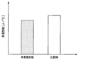
- FIG. 6 is an explanatory diagram for explaining the temperature raising performance of the battery cell 21 by the battery temperature controller 1 of the present embodiment.
- the left side shows the temperature rise performance when the battery temperature controller 1 of the present embodiment is used
- the right side shows the temperature rise performance when the battery temperature controller as a comparative example of the present embodiment is used.
- the performance shown on the left side of FIG. 6 is the temperature-raising performance of the battery cell 21 when the temperature controller 12 is arranged in a path component such as the positive terminal 212, the negative terminal 213, and the bus bar 22.
- the performance shown on the right side of FIG. 6 is the temperature rise performance of the battery cell 21 when the temperature controller 12 is arranged on the bottom surface of the case 211.
- the vertical axis in FIG. 6 indicates the amount of heat required to raise the temperature of the battery cell 21 by 1 ° C. under the same conditions.
- the battery cell 21 is smaller than the case where the temperature controller 12 is arranged on the bottom of the case 211. It can be seen that the temperature rises efficiently.
- the battery temperature control device 1 of the present disclosure it is possible to improve the efficiency of the temperature adjustment of the battery cell 21 while suppressing the restriction on the input and output of power in the battery module 2 due to the temperature adjustment of the battery cell 21. Can be.
- the temperature control body 12 of the present embodiment is constituted by the heater 14 including the heating resistor 141 that generates heat when energized and the insulator 142 having electrical insulation.
- an insulator 142 is arranged between the heating resistor 141 and the temperature control target so that the battery cell 21 and the heating resistor 141 are electrically insulated. According to this, the insulation between the heating resistor 141 and the temperature control target in the battery cell 21 is ensured by the insulator 142. Therefore, the temperature of the battery cell 21 can be appropriately adjusted by energizing the heating resistor 141 while ensuring insulation between the heating resistor 141 and the battery cell 21.
- connection between the plurality of temperature controllers 12 and the control circuit 100 is different from that of the first embodiment.
- portions different from the first embodiment will be mainly described, and description of the same portions as the first embodiment may be omitted.
- a plurality of temperature control bodies 12 are connected to the control circuit 100 via a temperature control wiring Lc independent of an external current path in the battery module 2. ing.
- the plurality of temperature control bodies 12 are individually connected to the control circuit 100 via the temperature control wiring Lc.
- the control circuit 100 is configured to individually adjust the amount of current supplied to the plurality of temperature regulators 12 so that the temperatures of the plurality of temperature regulators 12 can be individually adjusted.
- a temperature detecting section 8A capable of detecting the temperature of each of the battery cells 21 constituting the battery module 2 is connected.
- control circuit 100 is configured to supply current to each of the plurality of temperature regulators 12 when the temperature of each of the plurality of battery cells 21 is lower than a predetermined lower limit temperature, for example. Further, when the temperature of some of the plurality of battery cells 21 is lower than a predetermined lower limit temperature, the control circuit 100 energizes the temperature controller 12 corresponding to the certain number of battery cells 21; The power supply to the temperature controller 12 corresponding to the remaining battery cells 21 is stopped.
- the battery temperature control device 1 of the present embodiment can obtain the same operational effects as those of the first embodiment, which are provided by the same configuration as the first embodiment. This is the same in the following embodiments.
- the battery temperature controller 1 of the present embodiment is capable of individually adjusting the amount of electricity to be supplied to the plurality of temperature controllers 12 so that the temperatures of the plurality of temperature controllers 12 can be individually adjusted. According to this, even when the temperature of the battery cells 21 constituting the battery module 2 varies, the temperature of the battery cells 21 can be adjusted to an appropriate temperature. In addition, since the battery temperature control device 1 does not supply electricity to the battery cells 21 that do not need to perform temperature adjustment, the efficiency of temperature adjustment of the battery cells 21 can be improved.
- the present embodiment is different from the first embodiment in that the temperature control member 10 is configured to include the auxiliary temperature control body 16.
- the present embodiment portions different from the first embodiment will be mainly described, and description of the same portions as the first embodiment may be omitted.
- the temperature control member 10 includes an auxiliary temperature control body 16 configured to be able to adjust the temperature of the battery cell 21 separately from the temperature control body 12.
- the auxiliary temperature controller 16 is configured by a heater capable of securing insulation from the battery cell 21.
- the auxiliary temperature controller 16 is connected to the control circuit 100 so that the temperature of the battery cell 21 can be adjusted without using the power of the battery module 2.
- the control circuit 100 of the present embodiment controls the amount of power to the temperature controller 12 and the auxiliary temperature controller 16 based on the detection value of the temperature detector 8.
- the auxiliary temperature controller 16 is arranged so as to be in thermal contact with a portion of the battery cell 21 that is different from the portion where the temperature controller 12 is disposed, while being electrically insulated from the battery cell 21. I have.
- the auxiliary temperature control body 16 is a part of the battery cell 21 where the positive terminal 212, the negative terminal 213, and the bus bar 22 are provided so that the battery cell 21 is sandwiched between the temperature control body 12 and the auxiliary temperature control body 16. It is located at the site located on the opposite side.
- the auxiliary temperature controller 16 includes a bottom portion of the case portion 211 of the battery cell 21 where the positive terminal 212, the negative terminal 213, and the bus bar 22 are not provided. Are located in
- the soaking plate 17 is arranged between the auxiliary temperature controller 16 and the bottom of the case 211 so that the heat of the auxiliary temperature controller 16 can be easily transmitted to the entire battery cell 21.
- the heat equalizing plate 17 is made of a material having excellent heat conductivity.
- the heat equalizing plate 17 has a size capable of covering the entire bottom surface of the plurality of battery cells 21.
- the battery temperature control device 1 of the present embodiment has a configuration in which the temperature control member 10 includes not only the temperature control body 12 but also an auxiliary temperature control body 16. According to this, since the amount of heat input to the battery cell 21 can be increased, the time required to adjust the battery cell 21 to an appropriate temperature can be shortened. As a result, it is possible to control the temperature of the battery cell 21 with excellent immediate effect while suppressing the limitation of the input / output of the battery module 2 due to the temperature drop of the battery cell 21 or the like.
- the heat equalizing plate 17 is disposed between the auxiliary temperature controller 16 and the bottom of the case 211. According to this, since the heat of the auxiliary temperature regulator 16 is easily transmitted to the entire battery cell 21, it is possible to suppress the occurrence of a temperature distribution in the battery cell 21 when the temperature of the battery cell 21 is adjusted by the auxiliary temperature regulator 16. be able to.
- auxiliary temperature controller 16 is disposed on the bottom surface of the case 211
- the auxiliary temperature controller 16 may be disposed so as to be in thermal contact with a portion of the battery cell 21 different from the portion where the temperature controller 12 is disposed.
- the auxiliary temperature controller 16 may be arranged on a side surface of the case 211.
- the heat equalizing plate 17 be disposed between the auxiliary temperature controller 16 and the bottom surface of the case 211, but the present invention is not limited to this.
- the battery temperature control device 1 may be configured not to include the soaking plate 17.
- the present embodiment is different from the first embodiment in that the temperature controller 12 is constituted by an insulating heater 18.
- the present embodiment portions different from the first embodiment will be mainly described, and description of the same portions as the first embodiment may be omitted.
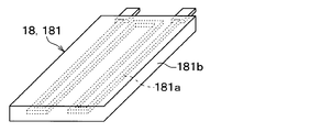
- the temperature controller 12 is constituted by an insulating heater 18 having electrical insulation.
- the insulating heater 18 constituting the temperature control body 12 is disposed so as to contact the positive terminal 212, the negative terminal 213, and the bus bar 22.
- the insulating heater 18 is composed of a silicon rubber heater 181 in which a heating resistor 181a that generates heat when energized is covered with a silicone rubber 181b.
- the heating resistor 181a is formed of a sheet-like conductor that generates Joule heat when energized.
- the temperature control body 12 includes an insulating heater 18 having electrical insulation. For this reason, the temperature of the battery cell 21 can be appropriately adjusted by the insulating heater 18 while ensuring insulation between the insulating heater 18 and the battery cell 21.
- the insulation heater 18 is constituted by a silicon rubber heater 181.
- the silicon rubber 181b covering the heating resistor 181a functions as an insulating member. Therefore, the temperature of the battery cell 21 can be appropriately adjusted by energizing the heating resistor 181a while ensuring insulation between the heating resistor 181a and the battery cell 21.
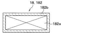
- the present embodiment is different from the fourth embodiment in that the insulating heater 18 is constituted by a ceramic heater 182.
- the insulating heater 18 is constituted by a ceramic heater 182.
- portions different from the fourth embodiment will be mainly described, and description of portions similar to the fourth embodiment may be omitted.
- the insulating heater 18 is composed of a ceramic heater 182 in which a heating resistor 182a that generates heat when energized is covered with a ceramic 182b.
- the heating resistor 182a is formed of a sheet-like conductor that generates Joule heat when energized.
- the insulating heater 18 forming the temperature control body 12 is configured by the ceramic heater 182. According to this, the ceramic 182b covering the heating resistor 182a functions as an insulating member. Therefore, the temperature of the battery cell 21 can be appropriately adjusted by energizing the heating resistor 182a while ensuring insulation between the heating resistor 182a and the battery cell 21.
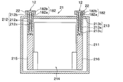
- the present embodiment is different from the first embodiment in that at least a part of the temperature controller 12 is buried in concave portions 212c and 213c formed in the positive terminal 212 and the negative terminal 213.
- portions different from the first embodiment will be mainly described, and description of the same portions as the first embodiment may be omitted.
- the positive electrode terminal 212 has a first concave portion 212 c that is recessed toward the inside of the case portion 211.
- the first concave portion 212c is formed as a bottomed cylindrical hole extending from the end face of the first outer connecting portion 212b toward the first inner connecting portion 212a. Note that the bottom of the first concave portion 212c is formed in the first inner connection portion 212a.
- the negative electrode terminal 213 has a second concave portion 213c that is depressed toward the inside of the case portion 211.
- the second concave portion 213c is formed of a bottomed cylindrical hole extending from the end face of the second outer connecting portion 213b toward the second inner connecting portion 213a. Note that the bottom of the second recess 213c is formed in the second inner connection portion 213a.
- the temperature controller 12 is constituted by the insulating heater 18 described in the fifth embodiment. That is, the temperature controller 12 is constituted by the ceramic heater 182.
- the temperature control body 12 is entirely buried inside the first concave portion 212c of the positive electrode terminal 212 and the second concave portion 213c of the negative electrode terminal 213.
- the temperature controller 12 is embedded in recesses 212 c and 213 c formed in the positive terminal 212 and the negative terminal 213. According to this, since the temperature control body 12 approaches the housing member and the electrolytic solution housed inside the case portion 211, the heat of the temperature control body 12 is easily transmitted to the housing member and the electrolyte sufficiently, and the temperature control body 12 Heat radiation is suppressed. Therefore, the temperature of the battery cell 21 can be efficiently adjusted.
- the temperature control body 12 is configured by the ceramic heater 182 which is the insulating heater 18 has been described, but the present invention is not limited to this.
- the temperature control body 12 includes the silicon rubber heater 181 described in the fourth embodiment and the heater 14 described in the first embodiment. May be.
- the temperature controller 12 is entirely embedded inside the first concave portion 212c of the positive electrode terminal 212 and the second concave portion 213c of the negative electrode terminal 213.
- the present invention is not limited to this. At least a part of the temperature control body 12 may be embedded inside the first concave portion 212c of the positive terminal 212 and the second concave portion 213c of the negative terminal 213.
- the battery temperature controller 1 has a configuration in which a concave portion is formed in one of the positive electrode terminal 212 and the negative electrode terminal 213 of the battery cell 21 and the temperature controller 12 is embedded in the concave portion of the electrode terminal. Is also good.
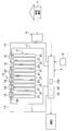
- a seventh embodiment will be described with reference to FIG.
- the present embodiment is different from the first embodiment in that a plurality of temperature regulators 12 operate using electric power from the battery module 2.
- portions different from the first embodiment will be mainly described, and description of the same portions as the first embodiment may be omitted.
- the control circuit 100 of the present embodiment is configured to control the temperature of the temperature control member 10. As shown in FIG. 17, the control circuit 100 is connected to the battery module 2 so that the battery module 2 can supply electricity to the temperature control member 10. Specifically, the control circuit 100 is connected to the battery module 2 via a branch line L2 branched from a connection line L1 connecting the voltage conversion device 3 and the battery module 2. Control circuit 100 is electrically connected in parallel to voltage conversion device 3 that controls the power to motor generator MG so that the power of battery module 2 can be supplied independently of the power supplied to motor generator MG. It is connected.
- the plurality of temperature control bodies 12 are connected to the control circuit 100 via the temperature control wiring Lc.
- the power of the battery module 2 is supplied to the plurality of temperature controllers 12 via the control circuit 100.
- the control circuit 100 of the present embodiment is configured to be able to supply the power of the battery module 2 to the temperature control member 10 independently of the power supplied to the motor generator MG.
- the plurality of temperature controllers 12 are connected to the control circuit 100 such that the power of the battery module 2 is supplied independently of the power supplied to the motor generator MG. .
- the motor generator MG and the plurality of temperature controllers 12 constitute a target device to which the battery module 2 supplies power.
- the voltage conversion device 3 and the control circuit 100 constitute a power conversion device that supplies necessary power to a plurality of target devices to be supplied with power.
- the battery temperature controller 1 of the present embodiment is configured such that the plurality of temperature controllers 12 can supply the power of the battery module 2 independently of the power supplied to the motor generator MG. According to this, the limitation of the output from the battery module 2 to the motor generator MG due to the temperature adjustment of the battery cells 21 by the plurality of temperature regulators 12 can be suppressed. That is, the temperature of the battery cell 21 can be appropriately adjusted by the temperature controller 12 irrespective of the discharge state of the battery module 2 to other target devices.
- the battery temperature control device 1 uses the positive electrode terminal 212, the negative electrode terminal 213, and the bus bar 22 as temperature control objects of the temperature control body 12. According to this, since the heat of the temperature control body 12 is easily transmitted to the housing member and the electrolytic solution housed inside the case portion 211, the temperature of the battery cell 21 can be adjusted from the inside. As described above, if the temperature of the battery cell 21 can be adjusted from the inside, heat radiation to the outside is suppressed, so that the temperature of the battery cell 21 can be efficiently adjusted.
- the present embodiment is different from the seventh embodiment in that the temperature control member 10 is configured to include an auxiliary temperature control body 16.
- the present embodiment parts different from the seventh embodiment will be mainly described, and description of the same parts as the seventh embodiment may be omitted.
- the temperature control member 10 includes an auxiliary temperature control body 16 configured to adjust the temperature of the battery cell 21 separately from the temperature control body 12.
- the auxiliary temperature controller 16 is configured by a heater capable of securing insulation from the battery cell 21.
- the auxiliary temperature controller 16 is connected to the control circuit 100 so that the power of the battery module 2 is supplied independently of the power supplied to the motor generator MG.
- the control circuit 100 of the present embodiment controls the amount of power to the temperature control body 12 and the auxiliary temperature control body 16 based on the value detected by the temperature detection unit 8.
- the auxiliary temperature controller 16 has the same configuration as that described in the third embodiment. In the present embodiment, the description of the details of the auxiliary temperature controller 16 is omitted.
- the battery temperature control device 1 of the present embodiment has a configuration in which the temperature control member 10 includes not only the temperature control body 12 but also an auxiliary temperature control body 16. According to this, since the amount of heat input to the battery cell 21 can be increased, the time required to adjust the battery cell 21 to an appropriate temperature can be shortened.
- the temperature controller 12 and the auxiliary temperature controller 16 are configured to be supplied with the power of the battery module 2 independently of the power supplied to the motor generator MG.
- the limitation of the output from battery module 2 to motor generator MG due to the temperature adjustment of battery cell 21 by temperature controller 12 and auxiliary temperature controller 16 is suppressed. That is, the temperature of the battery cell 21 can be appropriately adjusted by the temperature controller 12 and the auxiliary temperature controller 16 irrespective of the state of discharge to other target devices in the battery module 2.
- the temperature control member 10 has the same number of the temperature control bodies 12 as the bus bars 22 connecting the battery cells 21 to each other, but is not limited thereto.
- the temperature control member 10 may have, for example, a configuration including a smaller number of temperature control bodies 12 than the bus bar 22.
- the temperature control body 12 is configured by a heating element that generates heat when energized, but the present invention is not limited to this.
- the temperature control body 12 may be configured by, for example, a heat medium circulating unit such as a high-temperature pipe through which a high-temperature heat medium flows.
- the temperature control body 12 may be configured by a heat absorber whose one surface side becomes low temperature by energization, such as a Peltier module, for example.
- the temperature control body 12 may be configured by a refrigerant distribution unit such as a low-temperature pipe through which a low-temperature refrigerant flows.
- the battery temperature control device 1 of the present disclosure is applied to a device that adjusts the temperature of the battery module 2 mounted on a vehicle, but is not limited thereto.
- the battery temperature controller 1 is also applicable to, for example, a device that adjusts the temperature of a battery module 2 installed in a house or a factory.
- the battery temperature control device includes a temperature control member that controls the temperature of the battery module.
- the temperature control member includes a temperature control body configured to be able to adjust the temperature of the battery cell without using the power of the battery module.
- the temperature control body has at least a part of a path component constituting an external current path such as a pair of electrode terminals and a conductive member as a temperature control target, and is electrically insulated from a battery cell including the temperature control target. It is arranged so as to be in thermal contact with the temperature control target in the state.
- the temperature control member of the battery temperature control device includes an auxiliary temperature control body configured to be able to adjust the temperature of the battery cell without using the power of the battery module, separately from the temperature control body. Contains. Then, the auxiliary temperature controller is in a state of being electrically insulated from the battery cell including the temperature control target, and thermally contacting a portion of the battery cell different from the portion where the temperature controller is disposed. Are located in
- the battery cell is adjusted to an appropriate temperature.
- the time until the time can be shortened. Accordingly, it is possible to control the temperature of the battery cell excellent in immediate effect while suppressing the limitation of the input and output of the battery module due to the temperature drop of the battery cell and the like.
- the battery temperature control device includes a temperature control member that controls the temperature of the battery module.
- the temperature control member includes a temperature control body configured to adjust the temperature of the battery cell.
- the temperature controller is included in the target device and is connected to the power converter so that the power of the battery module is supplied independently of the power supplied to other target devices.
- the temperature control body has at least a part of a path constituting part constituting an external current path such as a pair of electrode terminals and a conductive member as a temperature control target, and is electrically insulated from a battery cell including the temperature control target. It is arranged so as to be in thermal contact with the temperature control target in the state in which the temperature control is performed.
- the temperature control member of the battery temperature control device includes, apart from the temperature control element, an auxiliary temperature control element configured to adjust the temperature of the battery cell.
- the auxiliary temperature controller is included in the target device and is connected to the power converter so that the power of the battery module is supplied independently of the power supplied to other target devices.
- the auxiliary temperature control body is configured to be in thermal contact with a part of the battery cell that is different from the part where the temperature control body is arranged, while being electrically insulated from the battery cell including the temperature control target. Are located in
- the temperature control body of the battery temperature control device is constituted by a heater including a heating resistor that generates heat when energized and an insulator having electrical insulation.
- a heater including a heating resistor that generates heat when energized and an insulator having electrical insulation.
- an insulator is arranged between the heating resistor and the temperature control target so that the battery cell and the heating resistor are electrically insulated. According to this, since the insulation between the heating resistor and the battery cell is ensured by the insulator, the temperature of the battery cell is controlled by energizing the heating resistor while ensuring the insulation between the heating resistor and the battery cell. Can be adjusted appropriately.
- the temperature controller of the battery temperature controller is constituted by an insulating heater having electrical insulation. And the insulation heater is arrange
- the insulating heater of the battery temperature control device is constituted by a silicon rubber heater in which a heating resistor that generates heat when energized is covered with silicon rubber. If a silicon rubber heater is adopted as the insulating heater, the silicon rubber covering the heating resistor functions as an insulating member. Therefore, it is possible to appropriately adjust the temperature of the battery cell by energizing the heating resistor while ensuring insulation between the heating resistor and the battery cell.
- the insulation heater of the battery temperature control device is constituted by a ceramic heater in which a heating resistor that generates heat when energized is covered with ceramics. If a ceramic heater is used as the insulating heater, the ceramic covering the heating resistor functions as an insulating member. Therefore, it is possible to appropriately adjust the temperature of the battery cell by energizing the heating resistor while ensuring insulation between the heating resistor and the battery cell.
- At least one of the pair of electrode terminal portions has a concave portion that is recessed toward the inside of the case portion.
- the temperature control body is at least partially embedded in the recess.
- the temperature control body approaches the housing member housed inside the case portion, the heat of the temperature control body is easily transmitted sufficiently to the housing member, and the heat radiation to the outside is suppressed. Therefore, the temperature adjustment of the battery cells can be efficiently performed.
Landscapes
- Engineering & Computer Science (AREA)
- Manufacturing & Machinery (AREA)
- Chemical & Material Sciences (AREA)
- Chemical Kinetics & Catalysis (AREA)
- Electrochemistry (AREA)
- General Chemical & Material Sciences (AREA)
- Secondary Cells (AREA)
- Physics & Mathematics (AREA)
- Electromagnetism (AREA)
Abstract
A battery temperature adjustment device (1) comprises a temperature adjustment member (10). Each of a plurality of battery cells (21) has: a case part (211), accommodation members (214, 215, 216) accommodated on the inner side of the case part; and a pair of electrode terminals (212, 213) projecting to the outer side of the case part and connected to the accommodation members. In adjacent battery cells among the plurality of battery cells, one of the pair of electrode terminals included in one battery cell is electrically connected to either of the pair of electrode terminals included in the other battery cell, with an electroconductive member interposed therebetween. The temperature adjustment member includes a temperature adjustment body constituted so as to be able to adjust the temperature of a battery cell without using the power of a battery module. The temperature adjustment body is such that at least some of the path-constituting parts constituting an external current path; i.e., the pair of electrode terminals and the electroconductive member, are used as temperature-adjustment objects, the battery adjustment body being disposed so as to thermally contact the temperature-adjustment objects when electrically insulated from the battery cell that includes the temperature-adjustment objects.
Description
本出願は、2018年6月26日に出願された日本特許出願番号2018-120963号に基づくもので、ここにその記載内容が参照により組み入れられる。
This application is based on Japanese Patent Application No. 2018-120963 filed on June 26, 2018, the disclosure of which is incorporated herein by reference.
本開示は、充放電可能な複数の電池セルが電導部材を介して電気的に接続された少なくとも1つの電池モジュールに適用される電池温調装置に関する。
The present disclosure relates to a battery temperature control device applied to at least one battery module in which a plurality of chargeable / dischargeable battery cells are electrically connected via a conductive member.
従来、二次電池である電池セルを加熱する加熱装置において、負の温度抵抗特性を有する抵抗体を電池セルに対して熱的に接触させることで、電池セルの過加熱を抑制するものが知られている(例えば、特許文献1参照)。
2. Description of the Related Art Conventionally, a heating device that heats a battery cell that is a secondary battery is known that suppresses overheating of the battery cell by thermally contacting a resistor having a negative temperature resistance characteristic with the battery cell. (For example, see Patent Document 1).
ところで、特許文献1記載の加熱装置は、複数の電池セルそれぞれが電気的に接続された電池モジュールにおける大電流が流れる電流経路に抵抗体が設けられている。具体的には、抵抗体は、各電池セルそれぞれに対して電気的に直列に接続されている。このため、例えば、抵抗体の電気抵抗が大きくなる条件下では、電池モジュールにおける電力の入出力が大幅に制限される。
本開示は、電池セルの温度調整に伴う電池モジュールにおける電力の入出力の制限を抑えつつ、電池セルの温度調整の効率向上を図ることを目的とする。 By the way, in the heating device described inPatent Document 1, a resistor is provided in a current path through which a large current flows in a battery module to which a plurality of battery cells are electrically connected. Specifically, the resistor is electrically connected in series to each of the battery cells. For this reason, for example, under conditions in which the electrical resistance of the resistor increases, the input / output of power in the battery module is greatly restricted.
An object of the present disclosure is to improve the efficiency of temperature adjustment of a battery cell while suppressing the restriction on input and output of power in a battery module due to the temperature adjustment of a battery cell.
本開示は、電池セルの温度調整に伴う電池モジュールにおける電力の入出力の制限を抑えつつ、電池セルの温度調整の効率向上を図ることを目的とする。 By the way, in the heating device described in
An object of the present disclosure is to improve the efficiency of temperature adjustment of a battery cell while suppressing the restriction on input and output of power in a battery module due to the temperature adjustment of a battery cell.
本開示は、充放電可能な複数の電池セルが電導部材を介して電気的に接続された少なくとも1つの電池モジュールに適用される電池温調装置を対象としている。
The present disclosure is directed to a battery temperature controller applied to at least one battery module in which a plurality of chargeable / dischargeable battery cells are electrically connected via a conductive member.
本開示の1つの観点によれば、電池温調装置は、電池モジュールの温度を調整する温調部材を備える。複数の電池セルそれぞれは、外殻を形成するケース部と、ケース部の内側に収容される収容部材と、ケース部の外側に突き出るとともに収容部材に連なる一対の電極端子と、を有している。複数の電池セルのうち隣接する電池セルは、一方の電池セルに含まれる一対の電極端子の一方が電導部材を介して他方の電池セルに含まれる一対の電極端子のいずれかに電気的に接続されている。温調部材は、電池モジュールの電力を利用することなく電池セルの温度を調整可能に構成される温調体を含んでいる。そして、温調体は、一対の電極端子および電導部材といった外部電流経路を構成する経路構成部の少なくとも一部を温調対象物とし、温調対象物を含む電池セルに対して電気的に絶縁された状態で温調対象物に対して熱的に接触するように配置されている。
According to one aspect of the present disclosure, a battery temperature control device includes a temperature control member that controls the temperature of a battery module. Each of the plurality of battery cells has a case part forming an outer shell, a housing member housed inside the case part, and a pair of electrode terminals protruding outside the case part and connected to the housing member. . One of a pair of electrode terminals included in one of the battery cells is electrically connected to one of a pair of electrode terminals included in the other battery cell via a conductive member. Have been. The temperature control member includes a temperature control body configured to be able to adjust the temperature of the battery cell without using the power of the battery module. In addition, the temperature control body has at least a part of a path component constituting an external current path such as a pair of electrode terminals and a conductive member as a temperature control target, and is electrically insulated from a battery cell including the temperature control target. It is arranged so as to be in thermal contact with the temperature control target in the state in which the temperature control is performed.
これによると、温調体による電池セルの温度調整に電池モジュールの電力を利用しないので、温調体による電池セルの温度調整に伴う電池モジュールの入出力の制限を抑えることができる。すなわち、電池モジュールの充放電状態によらず、温調体による電池セルの温度を適切に調整することができる。
According to this, since the power of the battery module is not used for the temperature adjustment of the battery cell by the temperature controller, the limitation of the input / output of the battery module due to the temperature adjustment of the battery cell by the temperature controller can be suppressed. That is, the temperature of the battery cell by the temperature controller can be appropriately adjusted regardless of the charge / discharge state of the battery module.
ここで、一対の電極端子は、ケース部の内側に収容される収容部材に連なっている。また、電導部材は、一対の電極端子の一方を介して収容部材に連なっている。このため、一対の電極端子および電導部材といった外部電流経路を構成する経路構成部を温調体の温調対象物とすれば、温調体の熱がケース部の内側に収容される収容部材に伝わり易くなるので、内側から電池セルの温度を調整することが可能となる。このように、内側から電池セルの温度を調整可能とすれば、外部への放熱が抑制されるので、電池セルの温度調整を効率よく実施することができる。
Here, the pair of electrode terminals are connected to a housing member housed inside the case portion. The conductive member is connected to the housing member via one of the pair of electrode terminals. For this reason, if the path component constituting the external current path, such as the pair of electrode terminals and the conductive member, is set as the temperature control target of the temperature control body, the heat of the temperature control body is stored in the housing member housed inside the case portion. Since the temperature can be easily transmitted, the temperature of the battery cell can be adjusted from the inside. As described above, if the temperature of the battery cell can be adjusted from the inside, the heat radiation to the outside is suppressed, so that the temperature of the battery cell can be efficiently adjusted.
本開示の別の観点によれば、電池温調装置は、電池モジュールの温度を調整する温調部材を備える。電池モジュールは、電力供給対象となる対象機器に対して必要な電力を供給可能なように電力変換装置に対して接続されている。複数の電池セルそれぞれは、外殻を形成するケース部と、ケース部の内側に収容される収容部材と、ケース部の外側に突き出るとともに収容部材に連なる一対の電極端子と、を有している。複数の電池セルのうち隣接する電池セルは、一方の電池セルに含まれる一対の電極端子の一方が電導部材を介して他方の電池セルに含まれる一対の電極端子のいずれかに電気的に接続されている。温調部材は、電池セルの温度を調整可能に構成される温調体を含んでいる。温調体は、対象機器に供給される電力から独立して電池モジュールの電力が供給されるように電力変換装置に接続されている。さらに、温調体は、一対の電極端子および電導部材といった外部電流経路を構成する経路構成部の少なくとも一部を温調対象物とし、温調対象物を含む電池セルに対して電気的に絶縁された状態で温調対象物に対して熱的に接触するように配置されている。
According to another aspect of the present disclosure, a battery temperature control device includes a temperature control member that controls a temperature of a battery module. The battery module is connected to the power converter so that necessary power can be supplied to a target device to be supplied with power. Each of the plurality of battery cells has a case part forming an outer shell, a housing member housed inside the case part, and a pair of electrode terminals protruding outside the case part and connected to the housing member. . One of a pair of electrode terminals included in one of the battery cells is electrically connected to one of a pair of electrode terminals included in the other battery cell via a conductive member. Have been. The temperature control member includes a temperature control body configured to adjust the temperature of the battery cell. The temperature controller is connected to the power converter so that the power of the battery module is supplied independently of the power supplied to the target device. Further, the temperature control body has at least a part of a path constituting part constituting an external current path such as a pair of electrode terminals and a conductive member as a temperature control target, and is electrically insulated from a battery cell including the temperature control target. It is arranged so as to be in thermal contact with the temperature control target in the state in which the temperature control is performed.
これによると、温調体が他の対象機器に供給される電力から独立して電池モジュールの電力が供給可能な構成になっているので、温調体による電池セルの温度調整に伴う電池モジュールから他の対象機器への出力の制限が抑えられる。すなわち、電池モジュールにおける他の対象機器への放電状態によらず、温調体によって電池セルの温度を適切に調整することができる。
According to this, since the temperature controller is configured to be able to supply the power of the battery module independently of the power supplied to the other target devices, the temperature controller controls the temperature of the battery cells by the temperature controller. Restrictions on output to other target devices can be suppressed. That is, the temperature of the battery cell can be appropriately adjusted by the temperature controller regardless of the discharge state of the battery module to another target device.
また、一対の電極端子および電導部材といった外部電流経路を構成する経路構成部を温調体の温調対象物としているので、内側から電池セルの温度を調整することが可能となる。このように、内側から電池セルの温度を調整可能とすれば、外部への放熱が抑制されるので、電池セルの温度調整を効率よく実施することができる。
Further, since the path components constituting the external current path, such as the pair of electrode terminals and the conductive member, are used as the temperature control target of the temperature control body, the temperature of the battery cells can be adjusted from the inside. As described above, if the temperature of the battery cell can be adjusted from the inside, the heat radiation to the outside is suppressed, so that the temperature of the battery cell can be efficiently adjusted.
このように、本開示の電池温調装置によれば、電池セルの温度調整に伴う電池モジュールにおける電力の入出力の制限を抑えつつ、電池セルの温度調整の効率向上を図ることができる。
As described above, according to the battery temperature control device of the present disclosure, it is possible to improve the efficiency of the temperature adjustment of the battery cell while suppressing the restriction on the input and output of power in the battery module due to the temperature adjustment of the battery cell.
ここで、「熱的に接触する」とは、部材同士とが直に接触している状態だけでなく、部材同士との間に空気層等の他の要素が介在する場合でも当該他の要素を介して部材間で間接的に熱が移動する状態も含まれる。
Here, the term “thermally contact” means not only a state in which the members are in direct contact with each other, but also a case in which another element such as an air layer is interposed between the members. And a state in which heat is indirectly transferred between members via the interface.
なお、各構成要素等に付された括弧付きの参照符号は、その構成要素等と後述する実施形態に記載の具体的な構成要素等との対応関係の一例を示すものである。
Note that reference numerals in parentheses attached to the respective components and the like indicate an example of the correspondence between the components and the like and specific components and the like described in the embodiments described later.
以下、本開示の実施形態について図面を参照して説明する。なお、以下の実施形態において、先行する実施形態で説明した事項と同一もしくは均等である部分には、同一の参照符号を付し、その説明を省略する場合がある。また、実施形態において、構成要素の一部だけを説明している場合、構成要素の他の部分に関しては、先行する実施形態において説明した構成要素を適用することができる。以下の実施形態は、特に組み合わせに支障が生じない範囲であれば、特に明示していない場合であっても、各実施形態同士を部分的に組み合わせることができる。
Hereinafter, embodiments of the present disclosure will be described with reference to the drawings. In the following embodiments, the same or equivalent parts as those described in the preceding embodiment are denoted by the same reference numerals, and description thereof may be omitted. Further, in the embodiment, when only a part of the component is described, the component described in the preceding embodiment can be applied to the other part of the component. The following embodiments can be partially combined with each other as long as the combination is not particularly hindered, even if not particularly specified.
(第1実施形態)
本実施形態について、図1~図6を参照して説明する。本実施形態では、本開示の電池温調装置1を車両に搭載された電池モジュール2の温度を調整する装置に適用した例について説明する。 (1st Embodiment)
This embodiment will be described with reference to FIGS. In the present embodiment, an example will be described in which the batterytemperature control device 1 of the present disclosure is applied to a device that adjusts the temperature of a battery module 2 mounted on a vehicle.
本実施形態について、図1~図6を参照して説明する。本実施形態では、本開示の電池温調装置1を車両に搭載された電池モジュール2の温度を調整する装置に適用した例について説明する。 (1st Embodiment)
This embodiment will be described with reference to FIGS. In the present embodiment, an example will be described in which the battery
電池温調装置1が搭載される車両としては、例えば、少なくとも1つの電池モジュール2を電源とするモータジェネレータMGによって走行可能な電気自動車、ハイブリッド自動車等が挙げられる。
車 両 As a vehicle on which the battery temperature control device 1 is mounted, for example, an electric vehicle, a hybrid vehicle, and the like, which can be driven by a motor generator MG that uses at least one battery module 2 as a power supply, can be given.
図1に示すように、電池モジュール2は、略直方体形状の電池セル21を積層配置した積層体で構成されている。複数の電池セル21それぞれは、充放電可能な二次電池(例えば、リチウムイオン電池、ニッケル水素電池)で構成されている。
As shown in FIG. 1, the battery module 2 is configured by a stacked body in which battery cells 21 having a substantially rectangular parallelepiped shape are stacked. Each of the plurality of battery cells 21 is configured by a chargeable / dischargeable secondary battery (for example, a lithium ion battery or a nickel metal hydride battery).
電池モジュール2を構成する複数の電池セル21は、互いに電気的に接続されている。具体的には、複数の電池セル21のうち隣接する電池セル21は、一方の電池セル21に含まれる一対の電極端子の一方が電導部材であるバスバー22を介して他方の電池セル21に含まれる一対の電極端子のいずれかに電気的に接続されている。本実施形態の複数の電池セル21は、バスバー22を介して電気的に直列に接続されている。なお、電池モジュール2は、複数の電池セル21の一部が電気的に並列に接続された構成になっていてもよい。また、図1では、12個の電池セル21で構成されている電池モジュール2を図示しているが、これに限定されない。電池モジュール2は、11個以下の電池セル21や、13個以上の電池セル21で構成されていてもよい。
複数 The plurality of battery cells 21 constituting the battery module 2 are electrically connected to each other. Specifically, one of the pair of electrode terminals included in one battery cell 21 is included in the other battery cell 21 via a bus bar 22 that is a conductive member. Is electrically connected to one of a pair of electrode terminals. The plurality of battery cells 21 of the present embodiment are electrically connected in series via a bus bar 22. Note that the battery module 2 may have a configuration in which some of the plurality of battery cells 21 are electrically connected in parallel. Further, FIG. 1 illustrates the battery module 2 including the twelve battery cells 21, but is not limited thereto. The battery module 2 may include 11 or less battery cells 21 or 13 or more battery cells 21.
ここで、電池セル21の詳細について図2を参照して説明する。なお、図2では、電池セル21の内部構成を説明するために、電池セル21の内部構成について点線で示している。
Here, the details of the battery cell 21 will be described with reference to FIG. In FIG. 2, the internal configuration of the battery cell 21 is indicated by a dotted line to explain the internal configuration of the battery cell 21.
図2に示すように、電池セル21は、外殻を形成するケース部211、正極端子212、負極端子213を含んで構成されている。本実施形態では、正極端子212および負極端子213がケース部211の外側に突き出る一対の電極端子を構成している。
(2) As shown in FIG. 2, the battery cell 21 is configured to include a case portion 211 forming an outer shell, a positive terminal 212, and a negative terminal 213. In the present embodiment, the positive electrode terminal 212 and the negative electrode terminal 213 constitute a pair of electrode terminals protruding outside the case portion 211.
ケース部211は、少なくとも外側に露出する部位が絶縁性を有する材料で構成された外装体である。ケース部211の内部には、電解液が注入されるとともに、発電要素として積層電極体214、正極集電体215、および負極集電体216が収容されている。本実施形態では、電解液、積層電極体214、正極集電体215、および負極集電体216が、ケース部211の内部に収容される収容部材を構成している。
The case portion 211 is an exterior body in which at least a portion exposed to the outside is made of a material having an insulating property. An electrolytic solution is injected into the case portion 211, and a stacked electrode body 214, a positive electrode current collector 215, and a negative electrode current collector 216 are housed as power generation elements. In the present embodiment, the electrolytic solution, the laminated electrode body 214, the positive electrode current collector 215, and the negative electrode current collector 216 constitute a housing member housed inside the case portion 211.
積層電極体214は、複数のセパレータ214a、複数の正極板214b、および複数の負極板214cを有する。積層電極体214は、セパレータ214aによって絶縁した状態で正極板214bと負極板214cとを交互に積層した積層体として構成されている。
The laminated electrode body 214 has a plurality of separators 214a, a plurality of positive plates 214b, and a plurality of negative plates 214c. The laminated electrode body 214 is configured as a laminated body in which positive electrodes 214b and negative electrodes 214c are alternately laminated while being insulated by the separator 214a.
複数の正極板214bは、それぞれの側端部が正極集電体215に対して電気的に接続されている。この正極集電体215は、正極端子212におけるケース部211の内側に位置する部位に対して電気的に接続されている。
(4) The plurality of positive electrode plates 214b have respective side ends electrically connected to the positive electrode current collector 215. The positive electrode current collector 215 is electrically connected to a portion of the positive electrode terminal 212 located inside the case 211.
複数の負極板214cは、それぞれの側端部が負極集電体216に対して電気的に接続されている。この負極集電体216は、負極端子213におけるケース部211の内側に位置する部位に対して電気的に接続されている。
(4) The plurality of negative electrode plates 214c have respective side ends electrically connected to the negative electrode current collector 216. The negative electrode current collector 216 is electrically connected to a portion of the negative electrode terminal 213 located inside the case portion 211.
正極端子212および負極端子213は、電導部材であるバスバー22とともに外部電流経路を構成する経路構成部である。具体的には、正極端子212および負極端子213は、棒状に形成された導電材料で構成されており、その一部がケース部211の内部に位置付けられ、残部が外側に突き出ている。正極端子212および負極端子213は、所定の間隔をあけた状態でケース部211における同じ端面から外側に向けて突き出ている。
(4) The positive electrode terminal 212 and the negative electrode terminal 213 are path components that form an external current path together with the bus bar 22 that is a conductive member. Specifically, the positive electrode terminal 212 and the negative electrode terminal 213 are made of a rod-shaped conductive material, a part of which is positioned inside the case part 211, and the remaining part protrudes outward. The positive electrode terminal 212 and the negative electrode terminal 213 protrude outward from the same end surface of the case portion 211 at a predetermined interval.
具体的には正極端子212は、ケース部211の内側に位置付けられる第1内側接続部212a、第1内側接続部212aに連なるとともにケース部211の外側に位置付けられる第1外側接続部212bを有している。第1内側接続部212aおよび第1外側接続部212bは、導電性を有する材料によって一体に形成されている。第1内側接続部212aは、ケース部211の内側に位置する端部が正極集電体215に対して電気的に接続されている。第1外側接続部212bは、ケース部211の外側に位置する端部がバスバー22に接続されている。これにより、正極端子212は、ケース部211の内部に収容された正極集電体215に連なっている。
Specifically, the positive electrode terminal 212 has a first inside connection portion 212a positioned inside the case portion 211, and a first outside connection portion 212b connected to the first inside connection portion 212a and positioned outside the case portion 211. ing. The first inner connection portion 212a and the first outer connection portion 212b are integrally formed of a conductive material. The first inner connection portion 212 a has an end located inside the case portion 211 and is electrically connected to the positive electrode current collector 215. The first outer connection portion 212 b has an end located outside the case portion 211 connected to the bus bar 22. As a result, the positive electrode terminal 212 is connected to the positive electrode current collector 215 housed inside the case portion 211.
負極端子213は、ケース部211の内側に位置付けられる第2内側接続部213a、第2内側接続部213aに連なるとともにケース部211の外側に位置付けられる第2外側接続部213bを有している。第2内側接続部213aおよび第2外側接続部213bは、導電性を有する材料によって一体に形成されている。第2内側接続部213aは、ケース部211の内側に位置する端部が負極集電体216に対して電気的に接続されている。第2外側接続部213bは、ケース部211の外側に位置する端部がバスバー22に接続されている。これにより、負極端子213は、ケース部211の内部に収容された負極集電体216に連なっている。
The negative electrode terminal 213 has a second inside connection portion 213a positioned inside the case portion 211, and a second outside connection portion 213b connected to the second inside connection portion 213a and positioned outside the case portion 211. The second inner connection portion 213a and the second outer connection portion 213b are integrally formed of a conductive material. The second inner connection portion 213 a has an end located inside the case portion 211 and is electrically connected to the negative electrode current collector 216. The second outer connection portion 213b has an end located outside the case portion 211 connected to the bus bar 22. Thus, the negative electrode terminal 213 is connected to the negative electrode current collector 216 housed inside the case portion 211.
図1に戻り、電池モジュール2は、電圧変換機器3を介してモータジェネレータMGに接続されている。モータジェネレータMGは、図示しない駆動輪と動力伝達可能に構成されている。モータジェネレータMGは、車両の走行動力源となり、また、回生駆動制御による発電機能を有している。本実施形態では、モータジェネレータMGが電池モジュール2の電力供給対象となる対象機器を構成する。
Returning to FIG. 1, the battery module 2 is connected to the motor generator MG via the voltage conversion device 3. Motor generator MG is configured to be able to transmit power to driving wheels (not shown). Motor generator MG serves as a driving power source for the vehicle, and has a power generation function by regenerative drive control. In the present embodiment, the motor generator MG constitutes a target device to which the battery module 2 supplies power.
電圧変換機器3は、電池モジュール2の出力電圧を所定の電圧を上限として昇圧させる昇圧コンバータ31および直流-交流で電力変換を実施するインバータ32等を含んで構成されている。本実施形態では、電圧変換機器3が電力供給対象となる対象機器に対して必要な電力を供給する電力変換装置を構成する。
The voltage converter 3 includes a boost converter 31 that boosts the output voltage of the battery module 2 up to a predetermined voltage as an upper limit, an inverter 32 that performs DC-AC power conversion, and the like. In the present embodiment, a power conversion device that supplies necessary power to a target device to which the voltage conversion device 3 supplies power is configured.
インバータ32は、周知のとおり複数の半導体スイッチング素子を備え、当該半導体スイッチング素子のスイッチング制御により直流-交流で電力変換を実施するものである。インバータ32は、モータジェネレータMGによる発電時に発電により生じた交流電力を直流電力に変換する。そして、インバータ32により変換された直流電力は電池モジュール2に充電される。また、インバータ32は、モータジェネレータMGによる車両走行時に電池モジュール2からの直流電力を交流電力に変換する。そして、インバータ32により変換された交流電力はモータジェネレータMGに供給される。
As is well known, the inverter 32 includes a plurality of semiconductor switching elements, and performs power conversion by DC-AC by switching control of the semiconductor switching elements. Inverter 32 converts AC power generated by power generation at the time of power generation by motor generator MG into DC power. Then, the DC power converted by the inverter 32 is charged in the battery module 2. In addition, inverter 32 converts DC power from battery module 2 into AC power when the vehicle is driven by motor generator MG. Then, the AC power converted by inverter 32 is supplied to motor generator MG.
車両には、電池モジュール2の充電および電池温調装置1の駆動を商用電源4によって行うための充電器6が搭載されている。この充電器6は、図示しない充電ケーブルによって商用電源4に接続可能に構成されている。これにより、電池モジュール2は、充電器6を介して商用電源4から供給される電力によって充電可能になっている。また、電池温調装置1は、充電器6を介して商用電源4から供給される電力によって駆動可能になっている。
The vehicle is equipped with a charger 6 for charging the battery module 2 and driving the battery temperature controller 1 by the commercial power supply 4. The charger 6 is configured to be connectable to the commercial power supply 4 by a charging cable (not shown). Thereby, the battery module 2 can be charged by the electric power supplied from the commercial power supply 4 via the charger 6. The battery temperature control device 1 can be driven by electric power supplied from the commercial power supply 4 via the charger 6.
電池温調装置1は、車両に搭載された電池モジュール2の温度を調整する装置である。電池温調装置1は、電池モジュール2の温度を調整する温調部材10および温調部材10の温度を制御する制御回路100を備えている。
The battery temperature control device 1 is a device that adjusts the temperature of the battery module 2 mounted on the vehicle. The battery temperature control device 1 includes a temperature control member 10 that controls the temperature of the battery module 2 and a control circuit 100 that controls the temperature of the temperature control member 10.
温調部材10は、電池セル21の温度を調整可能に構成される複数の温調体12を含んでいる。温調部材10は、電池セル21同士を接続するバスバー22と同数の温調体12を有している。複数の温調体12は、図3に示すように、電池モジュール2における外部電流経路から独立した温調用配線Lcを介して電気的に直列に接続されている。そして、温調部材10は、電池モジュール2における外部電流経路ではなく制御回路100から給電されるように、温調用配線Lcの両端が制御回路100に接続されている。
The temperature control member 10 includes a plurality of temperature control bodies 12 configured to be able to adjust the temperature of the battery cell 21. The temperature control member 10 has the same number of temperature control bodies 12 as the bus bars 22 connecting the battery cells 21 to each other. As shown in FIG. 3, the plurality of temperature control bodies 12 are electrically connected in series via a temperature control wiring Lc independent of an external current path in the battery module 2. The temperature control member 10 has both ends of the temperature control wiring Lc connected to the control circuit 100 so that power is supplied from the control circuit 100 instead of the external current path in the battery module 2.
ここで、二次電池で構成される電池セル21は、温度が低下すると内部抵抗が増大する傾向があり、低温環境下における放電容量が大幅に低下し易い。このため、低温環境下では、電池セル21を含む電池モジュール2を暖機する必要がある。
Here, the battery cell 21 composed of the secondary battery has a tendency that the internal resistance increases when the temperature decreases, and the discharge capacity under a low-temperature environment is apt to significantly decrease. Therefore, in a low-temperature environment, it is necessary to warm up the battery module 2 including the battery cells 21.
このような背景から電池セル21の暖機について本発明者らが鋭意検討した。この結果、電池セル21の内側から昇温させると、外部への放熱が抑制されることで、電池セル21の温度調整を効率よく実施できることが判った。
か ら From such a background, the present inventors diligently studied warm-up of the battery cell 21. As a result, it was found that when the temperature was increased from the inside of the battery cell 21, the heat radiation to the outside was suppressed, so that the temperature of the battery cell 21 could be efficiently adjusted.
これらを鑑みて、温調体12は、電池セル21の暖機が可能なように、通電により発熱する発熱体で構成されている。加えて、温調体12は、正極端子212、負極端子213、およびバスバー22といった外部電流経路を構成する経路構成部の少なくとも一部を温調対象物とし、当該温調対象物を含む電池セル21に対して熱的に接触するように配置されている。本実施形態の温調体12は、正極端子212、負極端子213、およびバスバー22といった経路構成部に対して絶縁性を有する接着剤等によって貼り付けられている。なお、温調体12は、接着剤以外の手法により正極端子212、負極端子213、およびバスバー22といった経路構成部に対して固定されていてもよい。
In view of these, the temperature control body 12 is formed of a heating element that generates heat when energized so that the battery cell 21 can be warmed up. In addition, the temperature control body 12 has at least a part of a path component constituting an external current path such as the positive terminal 212, the negative terminal 213, and the bus bar 22 as a temperature control target, and includes a battery cell including the temperature control target. It is arranged so as to be in thermal contact with 21. The temperature controller 12 of the present embodiment is attached to a path component such as the positive electrode terminal 212, the negative electrode terminal 213, and the bus bar 22 with an adhesive having an insulating property. In addition, the temperature control body 12 may be fixed to the path components such as the positive electrode terminal 212, the negative electrode terminal 213, and the bus bar 22 by a method other than the adhesive.
具体的には、図4または図5に示すように、温調体12は、通電により発熱する発熱抵抗体141および電気的な絶縁性を有する絶縁体142を備えるヒータ14で構成されている。発熱抵抗体141は、通電によりジュール熱を発生させるシート状の導体で構成される。
Specifically, as shown in FIG. 4 or FIG. 5, the temperature controller 12 includes a heater 14 having a heating resistor 141 that generates heat when energized and an insulator 142 having electrical insulation. The heating resistor 141 is formed of a sheet-like conductor that generates Joule heat when energized.
絶縁体142は、発熱抵抗体141と電池セル21とを電気的に絶縁するためのものであり、電気絶縁性に優れたシート状の絶縁材料(例えば、シリコンゴム)で構成されている。なお、発熱抵抗体141は、通電時に発熱するものであればよく、例えば、半導体で構成されていてもよい。
The insulator 142 is for electrically insulating the heating resistor 141 from the battery cell 21 and is made of a sheet-like insulating material (for example, silicon rubber) having excellent electrical insulation. The heating resistor 141 only needs to generate heat when energized, and may be made of, for example, a semiconductor.
このように構成される温調体12は、電池セル21と発熱抵抗体141とが電気的に絶縁されるように、発熱抵抗体141と電池セル21との間に絶縁体142が配置されている。具体的には、絶縁体142は、正極端子212、負極端子213、およびバスバー22といった経路構成部と発熱抵抗体141との間に配置されている。これにより、温調体12は、電池セル21に対して電気的に絶縁された状態で正極端子212、負極端子213、およびバスバー22といった経路構成部に対して熱的に接触するように配置されている。
In the temperature controller 12 thus configured, an insulator 142 is arranged between the heating resistor 141 and the battery cell 21 so that the battery cell 21 and the heating resistor 141 are electrically insulated. I have. Specifically, the insulator 142 is disposed between a path component such as the positive terminal 212, the negative terminal 213, and the bus bar 22 and the heating resistor 141. Thereby, the temperature control body 12 is disposed so as to be in thermal contact with the path components such as the positive terminal 212, the negative terminal 213, and the bus bar 22 while being electrically insulated from the battery cell 21. ing.
図1に戻り、制御回路100は、温調部材10への通電量を制御して温調部材10の温度を制御するものである。制御回路100は、電池モジュール2以外の電力供給源を利用して温調部材10の温度を制御する構成になっている。具体的には、制御回路100は、車載された補助バッテリ7から温調部材10に通電可能なように補助バッテリ7に対して接続されている。加えて、制御回路100は、商用電源4の電力を利用して温調部材10に通電可能なように充電器6に対して接続されている。これにより、本実施形態の温調部材10の温調体12は、電池モジュール2の電力を利用することなく電池セル21の温度を調整可能に構成されている。
Returning to FIG. 1, the control circuit 100 controls the temperature of the temperature control member 10 by controlling the amount of current supplied to the temperature control member 10. The control circuit 100 is configured to control the temperature of the temperature control member 10 using a power supply source other than the battery module 2. Specifically, the control circuit 100 is connected to the auxiliary battery 7 so that the temperature control member 10 can be energized from the auxiliary battery 7 mounted on the vehicle. In addition, the control circuit 100 is connected to the charger 6 so that the power of the commercial power supply 4 can be used to supply electricity to the temperature control member 10. Thereby, the temperature control body 12 of the temperature control member 10 of the present embodiment is configured to be able to adjust the temperature of the battery cell 21 without using the power of the battery module 2.
また、制御回路100には、電池モジュール2の温度を検出する温度検出部8が接続されている。温度検出部8は、例えば、電池モジュール2における代表的な部位の温度を検出する単一の温度センサや、電池セル21それぞれの温度を検出する複数の温度センサで構成される。
{Circle around (2)} The control circuit 100 is connected to a temperature detecting section 8 for detecting the temperature of the battery module 2. The temperature detection unit 8 includes, for example, a single temperature sensor that detects the temperature of a representative portion in the battery module 2 and a plurality of temperature sensors that detect the temperature of each of the battery cells 21.
制御回路100は、温度検出部8の検出値に基づいて温調部材10への通電量を制御する。制御回路100は、例えば、電池モジュール2の温度が所定の下限温度よりも低い場合に、補助バッテリ7または商用電源4の電力を利用して温調部材10に通電するように構成されている。また、制御回路100は、電池モジュール2の温度が適切温度範囲に到達すると、温調部材10に対する補助バッテリ7または商用電源4からの電力供給を停止するように構成されている。
The control circuit 100 controls the amount of power to the temperature control member 10 based on the value detected by the temperature detector 8. The control circuit 100 is configured to supply power to the temperature control member 10 using the power of the auxiliary battery 7 or the commercial power supply 4 when the temperature of the battery module 2 is lower than a predetermined lower limit temperature, for example. Further, the control circuit 100 is configured to stop the power supply from the auxiliary battery 7 or the commercial power supply 4 to the temperature control member 10 when the temperature of the battery module 2 reaches an appropriate temperature range.
次に、本実施形態の電池温調装置1の作動について説明する。電池モジュール2の温度が所定の下限温度よりも低い場合、制御回路100が温調部材10に対して通電する。この際、商用電源4の電力を利用することが可能な状況であれば、制御回路100は、充電器6を介して商用電源4の電力を温調部材10に供給する。また、商用電源4の電力を利用できない状況であれば、制御回路100は、補助バッテリ7の電力を温調部材10に供給する。これにより、ヒータ14の発熱抵抗体141が発熱することで、電池モジュール2が暖機される。
Next, the operation of the battery temperature control device 1 of the present embodiment will be described. When the temperature of the battery module 2 is lower than the predetermined lower limit temperature, the control circuit 100 energizes the temperature control member 10. At this time, if the power of the commercial power source 4 can be used, the control circuit 100 supplies the power of the commercial power source 4 to the temperature control member 10 via the charger 6. If the power of the commercial power supply 4 cannot be used, the control circuit 100 supplies the power of the auxiliary battery 7 to the temperature control member 10. As a result, the heat generating resistor 141 of the heater 14 generates heat, so that the battery module 2 is warmed up.
電池モジュール2の暖機によって電池モジュール2の温度が適切温度範囲に到達すると、制御回路100は、温調部材10に対する補助バッテリ7または商用電源4からの電力供給を停止する。これにより、電池モジュール2の過加熱が防止される。
(4) When the temperature of the battery module 2 reaches an appropriate temperature range due to the warm-up of the battery module 2, the control circuit 100 stops the power supply from the auxiliary battery 7 or the commercial power supply 4 to the temperature control member 10. Thereby, overheating of the battery module 2 is prevented.
以上説明した電池温調装置1は、温調部材10が、電池モジュール2の電力を利用することなく電池セル21の温度を調整可能に構成される温調体12を含んで構成されている。そして、温調体12は、正極端子212、負極端子213、およびバスバー22といった経路構成部の少なくとも一部を温調対象物とし、当該温調対象物を含む電池セル21に対して熱的に接触するように配置されている。
電池 The above-described battery temperature control device 1 is configured such that the temperature control member 10 includes the temperature control body 12 configured to be able to adjust the temperature of the battery cell 21 without using the power of the battery module 2. The temperature control body 12 uses at least a part of the path components such as the positive electrode terminal 212, the negative electrode terminal 213, and the bus bar 22 as a temperature control target, and thermally connects the battery cell 21 including the temperature control target. It is arranged to be in contact.
これによると、温調体12による電池セル21の温度調整に電池モジュール2の電力を利用しないので、温調体12による電池セル21の温度調整に伴う電池モジュール2の入出力の制限を抑えることができる。
According to this, since the power of the battery module 2 is not used for the temperature adjustment of the battery cell 21 by the temperature controller 12, the limitation of the input / output of the battery module 2 due to the temperature adjustment of the battery cell 21 by the temperature controller 12 is suppressed. Can be.
加えて、電池温調装置1は、正極端子212、負極端子213、およびバスバー22を温調体12の温調対象物としている。これによると、温調体12の熱がケース部211の内側に収容される収容部材や電解液に伝わり易くなるので、内側から電池セル21の温度を調整することが可能となる。このように、内側から電池セル21の温度を調整可能とすれば、外部への放熱が抑制されるので、電池セル21の温度調整を効率よく実施することができる。
In addition, the battery temperature control device 1 uses the positive electrode terminal 212, the negative electrode terminal 213, and the bus bar 22 as temperature control objects of the temperature control body 12. According to this, since the heat of the temperature control body 12 is easily transmitted to the housing member and the electrolytic solution housed inside the case portion 211, the temperature of the battery cell 21 can be adjusted from the inside. As described above, if the temperature of the battery cell 21 can be adjusted from the inside, heat radiation to the outside is suppressed, so that the temperature of the battery cell 21 can be efficiently adjusted.
ここで、図6は、本実施形態の電池温調装置1による電池セル21の昇温性能を説明するための説明図である。図6では、左側に本実施形態の電池温調装置1を用いた際の昇温性能を示し、右側に本実施形態の比較例となる電池温調装置を用いた際の昇温性能を示している。すなわち、図6の左側に示す性能は、温調体12を正極端子212、負極端子213、およびバスバー22といった経路構成部に配置した際の電池セル21の昇温性能である。一方、図6の右側に示す性能は、温調体12をケース部211の底面部に配置した際の電池セル21の昇温性能である。なお、図6の縦軸は、同じ条件下の元で電池セル21の温度を1℃昇温させるために必要な熱量を示している。
Here, FIG. 6 is an explanatory diagram for explaining the temperature raising performance of the battery cell 21 by the battery temperature controller 1 of the present embodiment. In FIG. 6, the left side shows the temperature rise performance when the battery temperature controller 1 of the present embodiment is used, and the right side shows the temperature rise performance when the battery temperature controller as a comparative example of the present embodiment is used. ing. That is, the performance shown on the left side of FIG. 6 is the temperature-raising performance of the battery cell 21 when the temperature controller 12 is arranged in a path component such as the positive terminal 212, the negative terminal 213, and the bus bar 22. On the other hand, the performance shown on the right side of FIG. 6 is the temperature rise performance of the battery cell 21 when the temperature controller 12 is arranged on the bottom surface of the case 211. The vertical axis in FIG. 6 indicates the amount of heat required to raise the temperature of the battery cell 21 by 1 ° C. under the same conditions.
図6に示すように、温調体12を正極端子212、負極端子213、およびバスバー22といった経路構成部に配置する場合、ケース部211の底面部に配置する場合に比べて、電池セル21が効率よく昇温することが判る。
As shown in FIG. 6, when the temperature control body 12 is arranged in a path component such as the positive electrode terminal 212, the negative electrode terminal 213, and the bus bar 22, the battery cell 21 is smaller than the case where the temperature controller 12 is arranged on the bottom of the case 211. It can be seen that the temperature rises efficiently.
このように、本開示の電池温調装置1によれば、電池セル21の温度調整に伴う電池モジュール2における電力の入出力の制限を抑えつつ、電池セル21の温度調整の効率向上を図ることができる。
As described above, according to the battery temperature control device 1 of the present disclosure, it is possible to improve the efficiency of the temperature adjustment of the battery cell 21 while suppressing the restriction on the input and output of power in the battery module 2 due to the temperature adjustment of the battery cell 21. Can be.
また、本実施形態の温調体12は、通電により発熱する発熱抵抗体141および電気的な絶縁性を有する絶縁体142を備えるヒータ14で構成されている。そして、ヒータ14は、電池セル21と発熱抵抗体141とが電気的に絶縁されるように、発熱抵抗体141と温調対象物との間に絶縁体142が配置されている。これによると、絶縁体142によって発熱抵抗体141と電池セル21における温調対象物との絶縁性が確保される。このため、発熱抵抗体141と電池セル21との絶縁性を確保しつつ、発熱抵抗体141への通電によって電池セル21の温度を適切に調整することができる。
{Circle around (2)} The temperature control body 12 of the present embodiment is constituted by the heater 14 including the heating resistor 141 that generates heat when energized and the insulator 142 having electrical insulation. In the heater 14, an insulator 142 is arranged between the heating resistor 141 and the temperature control target so that the battery cell 21 and the heating resistor 141 are electrically insulated. According to this, the insulation between the heating resistor 141 and the temperature control target in the battery cell 21 is ensured by the insulator 142. Therefore, the temperature of the battery cell 21 can be appropriately adjusted by energizing the heating resistor 141 while ensuring insulation between the heating resistor 141 and the battery cell 21.
(第2実施形態)
次に、第2実施形態について、図7、図8を参照して説明する。本実施形態では、複数の温調体12と制御回路100との接続態様が第1実施形態と異なっている。本実施形態では、第1実施形態と異なる部分について主に説明し、第1実施形態と同様の部分について説明を省略することがある。 (2nd Embodiment)
Next, a second embodiment will be described with reference to FIGS. In the present embodiment, the connection between the plurality oftemperature controllers 12 and the control circuit 100 is different from that of the first embodiment. In the present embodiment, portions different from the first embodiment will be mainly described, and description of the same portions as the first embodiment may be omitted.
次に、第2実施形態について、図7、図8を参照して説明する。本実施形態では、複数の温調体12と制御回路100との接続態様が第1実施形態と異なっている。本実施形態では、第1実施形態と異なる部分について主に説明し、第1実施形態と同様の部分について説明を省略することがある。 (2nd Embodiment)
Next, a second embodiment will be described with reference to FIGS. In the present embodiment, the connection between the plurality of
図7および図8に示すように、本実施形態の温調部材10は、電池モジュール2における外部電流経路から独立した温調用配線Lcを介して複数の温調体12が制御回路100に接続されている。複数の温調体12は、温調用配線Lcを介して制御回路100に対して個別に接続されている。
As shown in FIGS. 7 and 8, in the temperature control member 10 of the present embodiment, a plurality of temperature control bodies 12 are connected to the control circuit 100 via a temperature control wiring Lc independent of an external current path in the battery module 2. ing. The plurality of temperature control bodies 12 are individually connected to the control circuit 100 via the temperature control wiring Lc.
制御回路100は、複数の温調体12の温度を個別に調整可能なように、複数の温調体12に対する通電量を個別に調整可能に構成されている。制御回路100には、電池モジュール2を構成する電池セル21それぞれの温度を検出可能な温度検出部8Aが接続されている。
The control circuit 100 is configured to individually adjust the amount of current supplied to the plurality of temperature regulators 12 so that the temperatures of the plurality of temperature regulators 12 can be individually adjusted. To the control circuit 100, a temperature detecting section 8A capable of detecting the temperature of each of the battery cells 21 constituting the battery module 2 is connected.
具体的には、制御回路100は、例えば、複数の電池セル21それぞれの温度が所定の下限温度よりも低い場合に複数の温調体12それぞれに通電するように構成されている。また、制御回路100は、複数の電池セル21のうち一部の電池セル21の温度が所定の下限温度よりも低い場合、当該一部の電池セル21に対応する温調体12に通電し、残りの電池セル21に対応する温調体12への通電を停止するように構成されている。
Specifically, the control circuit 100 is configured to supply current to each of the plurality of temperature regulators 12 when the temperature of each of the plurality of battery cells 21 is lower than a predetermined lower limit temperature, for example. Further, when the temperature of some of the plurality of battery cells 21 is lower than a predetermined lower limit temperature, the control circuit 100 energizes the temperature controller 12 corresponding to the certain number of battery cells 21; The power supply to the temperature controller 12 corresponding to the remaining battery cells 21 is stopped.
その他の構成は、第1実施形態と同様である。本実施形態の電池温調装置1は、第1実施形態と共通の構成から奏される作用効果を第1実施形態と同様に得ることができる。このことは、以降の実施形態においても同様である。
Other configurations are the same as in the first embodiment. The battery temperature control device 1 of the present embodiment can obtain the same operational effects as those of the first embodiment, which are provided by the same configuration as the first embodiment. This is the same in the following embodiments.
本実施形態の電池温調装置1は、複数の温調体12の温度を個別に調整可能なように、複数の温調体12に対する通電量を個別に調整可能になっている。これによると、電池モジュール2を構成する電池セル21に温度のばらつきが生じた場合であっても、電池セル21の温度を適切な温度に調整することができる。また、電池温調装置1は、温度調整を行う必要がない電池セル21に対して通電しないので、電池セル21の温度調整の効率向上を図ることができる。
電池 The battery temperature controller 1 of the present embodiment is capable of individually adjusting the amount of electricity to be supplied to the plurality of temperature controllers 12 so that the temperatures of the plurality of temperature controllers 12 can be individually adjusted. According to this, even when the temperature of the battery cells 21 constituting the battery module 2 varies, the temperature of the battery cells 21 can be adjusted to an appropriate temperature. In addition, since the battery temperature control device 1 does not supply electricity to the battery cells 21 that do not need to perform temperature adjustment, the efficiency of temperature adjustment of the battery cells 21 can be improved.
(第3実施形態)
次に、第3実施形態について、図9~図11を参照して説明する。本実施形態では、温調部材10が補助温調体16を含んで構成されている点が第1実施形態と相違している。本実施形態では、第1実施形態と異なる部分について主に説明し、第1実施形態と同様の部分について説明を省略することがある。 (Third embodiment)
Next, a third embodiment will be described with reference to FIGS. The present embodiment is different from the first embodiment in that thetemperature control member 10 is configured to include the auxiliary temperature control body 16. In the present embodiment, portions different from the first embodiment will be mainly described, and description of the same portions as the first embodiment may be omitted.
次に、第3実施形態について、図9~図11を参照して説明する。本実施形態では、温調部材10が補助温調体16を含んで構成されている点が第1実施形態と相違している。本実施形態では、第1実施形態と異なる部分について主に説明し、第1実施形態と同様の部分について説明を省略することがある。 (Third embodiment)
Next, a third embodiment will be described with reference to FIGS. The present embodiment is different from the first embodiment in that the
図9に示すように、温調部材10は、温調体12とは別に、電池セル21の温度を調整可能に構成される補助温調体16を含んでいる。補助温調体16は、電池セル21との絶縁性が確保可能なヒータで構成されている。補助温調体16は、電池モジュール2の電力を利用することなく電池セル21の温度を調整可能なように、制御回路100に対して接続されている。なお、本実施形態の制御回路100は、温度検出部8の検出値に基づいて温調体12および補助温調体16への通電量を制御する。
As shown in FIG. 9, the temperature control member 10 includes an auxiliary temperature control body 16 configured to be able to adjust the temperature of the battery cell 21 separately from the temperature control body 12. The auxiliary temperature controller 16 is configured by a heater capable of securing insulation from the battery cell 21. The auxiliary temperature controller 16 is connected to the control circuit 100 so that the temperature of the battery cell 21 can be adjusted without using the power of the battery module 2. In addition, the control circuit 100 of the present embodiment controls the amount of power to the temperature controller 12 and the auxiliary temperature controller 16 based on the detection value of the temperature detector 8.
補助温調体16は、電池セル21に対して電気的に絶縁された状態で電池セル21のうち温調体12が配置された部位とは異なる部位に熱的に接触するように配置されている。補助温調体16は、電池セル21が温調体12と補助温調体16とで挟まれるように、電池セル21のうち正極端子212、負極端子213、およびバスバー22が設けられた部位の反対側に位置する部位に配置されている。
The auxiliary temperature controller 16 is arranged so as to be in thermal contact with a portion of the battery cell 21 that is different from the portion where the temperature controller 12 is disposed, while being electrically insulated from the battery cell 21. I have. The auxiliary temperature control body 16 is a part of the battery cell 21 where the positive terminal 212, the negative terminal 213, and the bus bar 22 are provided so that the battery cell 21 is sandwiched between the temperature control body 12 and the auxiliary temperature control body 16. It is located at the site located on the opposite side.
具体的には、補助温調体16は、図10および図11に示すように、電池セル21のうち、正極端子212、負極端子213、およびバスバー22が設けられていないケース部211の底面部に配置されている。
Specifically, as shown in FIGS. 10 and 11, the auxiliary temperature controller 16 includes a bottom portion of the case portion 211 of the battery cell 21 where the positive terminal 212, the negative terminal 213, and the bus bar 22 are not provided. Are located in
また、補助温調体16とケース部211の底面部との間には、補助温調体16の熱が電池セル21の全体に伝わり易くなるように均熱板17が配置されている。均熱板17は、熱伝導性に優れた材料で構成されている。均熱板17は、複数の電池セル21の底面部の全体を覆うことが可能な大きさを有している。
{Circle around (2)} The soaking plate 17 is arranged between the auxiliary temperature controller 16 and the bottom of the case 211 so that the heat of the auxiliary temperature controller 16 can be easily transmitted to the entire battery cell 21. The heat equalizing plate 17 is made of a material having excellent heat conductivity. The heat equalizing plate 17 has a size capable of covering the entire bottom surface of the plurality of battery cells 21.
その他の構成は、第1実施形態と同様である。本実施形態の電池温調装置1は、温調部材10が温調体12だけでなく補助温調体16を備える構成になっている。これによると、電池セル21への投入熱量を増大させることができるので、電池セル21を適切な温度に調整するまでの時間を短縮することができる。この結果、電池セル21の温度低下等に起因する電池モジュール2における入出力の制限を抑えつつ、即効性に優れた電池セル21の温度調整を実施することが可能になる。
Other configurations are the same as in the first embodiment. The battery temperature control device 1 of the present embodiment has a configuration in which the temperature control member 10 includes not only the temperature control body 12 but also an auxiliary temperature control body 16. According to this, since the amount of heat input to the battery cell 21 can be increased, the time required to adjust the battery cell 21 to an appropriate temperature can be shortened. As a result, it is possible to control the temperature of the battery cell 21 with excellent immediate effect while suppressing the limitation of the input / output of the battery module 2 due to the temperature drop of the battery cell 21 or the like.
加えて、本実施形態の電池温調装置1は、補助温調体16とケース部211の底面部との間に均熱板17が配置されている。これによると、補助温調体16の熱が電池セル21の全体に伝わり易くなるので、補助温調体16による電池セル21の温度調整時に電池セル21に温度分布が生じてしまうことを抑制することができる。
In addition, in the battery temperature controller 1 of the present embodiment, the heat equalizing plate 17 is disposed between the auxiliary temperature controller 16 and the bottom of the case 211. According to this, since the heat of the auxiliary temperature regulator 16 is easily transmitted to the entire battery cell 21, it is possible to suppress the occurrence of a temperature distribution in the battery cell 21 when the temperature of the battery cell 21 is adjusted by the auxiliary temperature regulator 16. be able to.
(第3実施形態の変形例)
上述の第3実施形態では、補助温調体16がケース部211の底面部に配置されるものを例示したが、これに限定されない。補助温調体16は、電池セル21のうち温調体12が配置された部位とは異なる部位において熱的に接触するように配置されていればよい。例えば、補助温調体16は、ケース部211の側面部に配置されていてもよい。 (Modification of Third Embodiment)
In the above-described third embodiment, an example in which theauxiliary temperature controller 16 is disposed on the bottom surface of the case 211 has been described, but the present invention is not limited to this. The auxiliary temperature controller 16 may be disposed so as to be in thermal contact with a portion of the battery cell 21 different from the portion where the temperature controller 12 is disposed. For example, the auxiliary temperature controller 16 may be arranged on a side surface of the case 211.
上述の第3実施形態では、補助温調体16がケース部211の底面部に配置されるものを例示したが、これに限定されない。補助温調体16は、電池セル21のうち温調体12が配置された部位とは異なる部位において熱的に接触するように配置されていればよい。例えば、補助温調体16は、ケース部211の側面部に配置されていてもよい。 (Modification of Third Embodiment)
In the above-described third embodiment, an example in which the
また、上述の第3実施形態の如く、補助温調体16とケース部211の底面部との間に均熱板17が配置されていることが望ましいが、これに限定されない。電池温調装置1は、均熱板17を備えていない構成になっていてもよい。
Also, as in the above-described third embodiment, it is desirable that the heat equalizing plate 17 be disposed between the auxiliary temperature controller 16 and the bottom surface of the case 211, but the present invention is not limited to this. The battery temperature control device 1 may be configured not to include the soaking plate 17.
(第4実施形態)
次に、第4実施形態について、図12、図13を参照して説明する。本実施形態では、温調体12が絶縁ヒータ18で構成されている点が第1実施形態と相違している。本実施形態では、第1実施形態と異なる部分について主に説明し、第1実施形態と同様の部分について説明を省略することがある。 (Fourth embodiment)
Next, a fourth embodiment will be described with reference to FIGS. The present embodiment is different from the first embodiment in that thetemperature controller 12 is constituted by an insulating heater 18. In the present embodiment, portions different from the first embodiment will be mainly described, and description of the same portions as the first embodiment may be omitted.
次に、第4実施形態について、図12、図13を参照して説明する。本実施形態では、温調体12が絶縁ヒータ18で構成されている点が第1実施形態と相違している。本実施形態では、第1実施形態と異なる部分について主に説明し、第1実施形態と同様の部分について説明を省略することがある。 (Fourth embodiment)
Next, a fourth embodiment will be described with reference to FIGS. The present embodiment is different from the first embodiment in that the
図12に示すように、温調体12は、電気的な絶縁性を有する絶縁ヒータ18で構成されている。温調体12を構成する絶縁ヒータ18は、正極端子212、負極端子213、およびバスバー22に当接するように配置されている。
温 As shown in FIG. 12, the temperature controller 12 is constituted by an insulating heater 18 having electrical insulation. The insulating heater 18 constituting the temperature control body 12 is disposed so as to contact the positive terminal 212, the negative terminal 213, and the bus bar 22.
図12および図13に示すように、絶縁ヒータ18は、通電により発熱する発熱抵抗体181aがシリコンゴム181bで覆われるシリコンラバーヒータ181で構成されている。なお、発熱抵抗体181aは、通電によりジュール熱を発生させるシート状の導体で構成される。
As shown in FIGS. 12 and 13, the insulating heater 18 is composed of a silicon rubber heater 181 in which a heating resistor 181a that generates heat when energized is covered with a silicone rubber 181b. The heating resistor 181a is formed of a sheet-like conductor that generates Joule heat when energized.
その他の構成は、第1実施形態と同様である。本実施形態の電池温調装置1は、温調体12が、電気的な絶縁性を有する絶縁ヒータ18で構成されている。このため、絶縁ヒータ18と電池セル21との絶縁性を確保しつつ、絶縁ヒータ18によって電池セル21の温度を適切に調整することができる。
Other configurations are the same as in the first embodiment. In the battery temperature control device 1 of the present embodiment, the temperature control body 12 includes an insulating heater 18 having electrical insulation. For this reason, the temperature of the battery cell 21 can be appropriately adjusted by the insulating heater 18 while ensuring insulation between the insulating heater 18 and the battery cell 21.
具体的には、絶縁ヒータ18は、シリコンラバーヒータ181で構成されている。これによれば、発熱抵抗体181aを覆うシリコンゴム181bが絶縁部材として機能する。このため、発熱抵抗体181aと電池セル21との絶縁性を確保しつつ、発熱抵抗体181aへの通電によって電池セル21の温度を適切に調整することができる。
Specifically, the insulation heater 18 is constituted by a silicon rubber heater 181. According to this, the silicon rubber 181b covering the heating resistor 181a functions as an insulating member. Therefore, the temperature of the battery cell 21 can be appropriately adjusted by energizing the heating resistor 181a while ensuring insulation between the heating resistor 181a and the battery cell 21.
(第5実施形態)
次に、第5実施形態について、図14を参照して説明する。本実施形態では、絶縁ヒータ18がセラミックヒータ182で構成されている点が第4実施形態と異なっている。本実施形態では、第4実施形態と異なる部分について主に説明し、第4実施形態と同様の部分について説明を省略することがある。 (Fifth embodiment)
Next, a fifth embodiment will be described with reference to FIG. The present embodiment is different from the fourth embodiment in that the insulatingheater 18 is constituted by a ceramic heater 182. In the present embodiment, portions different from the fourth embodiment will be mainly described, and description of portions similar to the fourth embodiment may be omitted.
次に、第5実施形態について、図14を参照して説明する。本実施形態では、絶縁ヒータ18がセラミックヒータ182で構成されている点が第4実施形態と異なっている。本実施形態では、第4実施形態と異なる部分について主に説明し、第4実施形態と同様の部分について説明を省略することがある。 (Fifth embodiment)
Next, a fifth embodiment will be described with reference to FIG. The present embodiment is different from the fourth embodiment in that the insulating
図14に示すように、絶縁ヒータ18は、通電により発熱する発熱抵抗体182aがセラミックス182bで覆われるセラミックヒータ182で構成されている。なお、発熱抵抗体182aは、通電によりジュール熱を発生させるシート状の導体で構成される。
As shown in FIG. 14, the insulating heater 18 is composed of a ceramic heater 182 in which a heating resistor 182a that generates heat when energized is covered with a ceramic 182b. The heating resistor 182a is formed of a sheet-like conductor that generates Joule heat when energized.
その他の構成は、第4実施形態と同様である。本実施形態の電池温調装置1は、温調体12を構成する絶縁ヒータ18がセラミックヒータ182で構成されている。これによると、発熱抵抗体182aを覆うセラミックス182bが絶縁部材として機能する。このため、発熱抵抗体182aと電池セル21との絶縁性を確保しつつ、発熱抵抗体182aへの通電によって電池セル21の温度を適切に調整することができる。
Other configurations are the same as in the fourth embodiment. In the battery temperature control device 1 of the present embodiment, the insulating heater 18 forming the temperature control body 12 is configured by the ceramic heater 182. According to this, the ceramic 182b covering the heating resistor 182a functions as an insulating member. Therefore, the temperature of the battery cell 21 can be appropriately adjusted by energizing the heating resistor 182a while ensuring insulation between the heating resistor 182a and the battery cell 21.
(第6実施形態)
次に、第6実施形態について、図15、図16を参照して説明する。本実施形態では、温調体12の少なくとも一部が正極端子212および負極端子213に形成された凹部212c、213cに埋設されている点が第1実施形態と相違している。本実施形態では、第1実施形態と異なる部分について主に説明し、第1実施形態と同様の部分について説明を省略することがある。 (Sixth embodiment)
Next, a sixth embodiment will be described with reference to FIGS. The present embodiment is different from the first embodiment in that at least a part of thetemperature controller 12 is buried in concave portions 212c and 213c formed in the positive terminal 212 and the negative terminal 213. In the present embodiment, portions different from the first embodiment will be mainly described, and description of the same portions as the first embodiment may be omitted.
次に、第6実施形態について、図15、図16を参照して説明する。本実施形態では、温調体12の少なくとも一部が正極端子212および負極端子213に形成された凹部212c、213cに埋設されている点が第1実施形態と相違している。本実施形態では、第1実施形態と異なる部分について主に説明し、第1実施形態と同様の部分について説明を省略することがある。 (Sixth embodiment)
Next, a sixth embodiment will be described with reference to FIGS. The present embodiment is different from the first embodiment in that at least a part of the
図15および図16に示すように、正極端子212には、ケース部211の内側に向かって窪んだ第1凹部212cが形成されている。この第1凹部212cは、第1外側接続部212bの端面から第1内側接続部212a側に向かって延びる有底筒状の穴で構成されている。なお、第1凹部212cの底部は、第1内側接続部212aに形成される。
As shown in FIGS. 15 and 16, the positive electrode terminal 212 has a first concave portion 212 c that is recessed toward the inside of the case portion 211. The first concave portion 212c is formed as a bottomed cylindrical hole extending from the end face of the first outer connecting portion 212b toward the first inner connecting portion 212a. Note that the bottom of the first concave portion 212c is formed in the first inner connection portion 212a.
一方、負極端子213には、ケース部211の内側に向かって窪んだ第2凹部213cが形成されている。この第2凹部213cは、第2外側接続部213bの端面から第2内側接続部213a側に向かって延びる有底筒状の穴で構成されている。なお、第2凹部213cの底部は、第2内側接続部213aに形成される。
On the other hand, the negative electrode terminal 213 has a second concave portion 213c that is depressed toward the inside of the case portion 211. The second concave portion 213c is formed of a bottomed cylindrical hole extending from the end face of the second outer connecting portion 213b toward the second inner connecting portion 213a. Note that the bottom of the second recess 213c is formed in the second inner connection portion 213a.
また、温調体12は、第5実施形態で説明した絶縁ヒータ18で構成されている。すなわち、温調体12は、セラミックヒータ182で構成されている。そして、温調体12は、その全体が正極端子212の第1凹部212cおよび負極端子213の第2凹部213cの内側に埋設されている。
{Circle around (5)} The temperature controller 12 is constituted by the insulating heater 18 described in the fifth embodiment. That is, the temperature controller 12 is constituted by the ceramic heater 182. The temperature control body 12 is entirely buried inside the first concave portion 212c of the positive electrode terminal 212 and the second concave portion 213c of the negative electrode terminal 213.
その他の構成は、第1実施形態と同様である。本実施形態の電池温調装置1は、温調体12が正極端子212および負極端子213に形成された凹部212c、213cに埋設されている。これによると、温調体12がケース部211の内側に収容される収容部材や電解液に近づくので、温調体12の熱が収容部材や電解液に充分に伝わり易くなるとともに、外部への放熱が抑制される。このため、電池セル21の温度調整を効率よく実施することができる。
Other configurations are the same as in the first embodiment. In the battery temperature controller 1 of the present embodiment, the temperature controller 12 is embedded in recesses 212 c and 213 c formed in the positive terminal 212 and the negative terminal 213. According to this, since the temperature control body 12 approaches the housing member and the electrolytic solution housed inside the case portion 211, the heat of the temperature control body 12 is easily transmitted to the housing member and the electrolyte sufficiently, and the temperature control body 12 Heat radiation is suppressed. Therefore, the temperature of the battery cell 21 can be efficiently adjusted.
(第6実施形態の変形例)
上述の第6実施形態では、温調体12が絶縁ヒータ18であるセラミックヒータ182で構成されている例について説明したが、これに限定されない。温調体12は、電池セル21との絶縁性を確保可能なものであれば、例えば、第4実施形態で説明したがシリコンラバーヒータ181や、第1実施形態で説明したヒータ14で構成されていてもよい。 (Modification of the sixth embodiment)
In the above-described sixth embodiment, the example in which thetemperature control body 12 is configured by the ceramic heater 182 which is the insulating heater 18 has been described, but the present invention is not limited to this. As long as the temperature control body 12 can ensure insulation from the battery cell 21, for example, the temperature control body 12 includes the silicon rubber heater 181 described in the fourth embodiment and the heater 14 described in the first embodiment. May be.
上述の第6実施形態では、温調体12が絶縁ヒータ18であるセラミックヒータ182で構成されている例について説明したが、これに限定されない。温調体12は、電池セル21との絶縁性を確保可能なものであれば、例えば、第4実施形態で説明したがシリコンラバーヒータ181や、第1実施形態で説明したヒータ14で構成されていてもよい。 (Modification of the sixth embodiment)
In the above-described sixth embodiment, the example in which the
上述の第6実施形態では、温調体12の全体が正極端子212の第1凹部212cおよび負極端子213の第2凹部213cの内側に埋設されているものを例示したが、これに限定されない。温調体12は、少なくとも一部が、正極端子212の第1凹部212cおよび負極端子213の第2凹部213cの内側に埋設されていてもよい。
In the sixth embodiment described above, the temperature controller 12 is entirely embedded inside the first concave portion 212c of the positive electrode terminal 212 and the second concave portion 213c of the negative electrode terminal 213. However, the present invention is not limited to this. At least a part of the temperature control body 12 may be embedded inside the first concave portion 212c of the positive terminal 212 and the second concave portion 213c of the negative terminal 213.
また、電池温調装置1は、電池セル21における正極端子212および負極端子213の一方の電極端子に凹部が形成され、当該電極端子の凹部に温調体12が埋設された構成になっていてもよい。
Further, the battery temperature controller 1 has a configuration in which a concave portion is formed in one of the positive electrode terminal 212 and the negative electrode terminal 213 of the battery cell 21 and the temperature controller 12 is embedded in the concave portion of the electrode terminal. Is also good.
(第7実施形態)
次に、第7実施形態について、図17を参照して説明する。本実施形態では、複数の温調体12が電池モジュール2からの電力を利用して作動する構成になっている点が第1実施形態と異なっている。本実施形態では、第1実施形態と異なる部分について主に説明し、第1実施形態と同様の部分について説明を省略することがある。 (Seventh embodiment)
Next, a seventh embodiment will be described with reference to FIG. The present embodiment is different from the first embodiment in that a plurality oftemperature regulators 12 operate using electric power from the battery module 2. In the present embodiment, portions different from the first embodiment will be mainly described, and description of the same portions as the first embodiment may be omitted.
次に、第7実施形態について、図17を参照して説明する。本実施形態では、複数の温調体12が電池モジュール2からの電力を利用して作動する構成になっている点が第1実施形態と異なっている。本実施形態では、第1実施形態と異なる部分について主に説明し、第1実施形態と同様の部分について説明を省略することがある。 (Seventh embodiment)
Next, a seventh embodiment will be described with reference to FIG. The present embodiment is different from the first embodiment in that a plurality of
本実施形態の制御回路100は、温調部材10の温度を制御可能な構成になっている。図17に示すように、制御回路100は、電池モジュール2から温調部材10に通電可能なように電池モジュール2に対して接続されている。具体的には、制御回路100は、電圧変換機器3と電池モジュール2とを接続する接続配線L1から分岐する分岐配線L2を介して電池モジュール2に接続されている。制御回路100は、モータジェネレータMGに供給される電力から独立して電池モジュール2の電力を供給可能なように、モータジェネレータMGへの電力を制御する電圧変換機器3に対して電気的に並列に接続されている。
制 御 The control circuit 100 of the present embodiment is configured to control the temperature of the temperature control member 10. As shown in FIG. 17, the control circuit 100 is connected to the battery module 2 so that the battery module 2 can supply electricity to the temperature control member 10. Specifically, the control circuit 100 is connected to the battery module 2 via a branch line L2 branched from a connection line L1 connecting the voltage conversion device 3 and the battery module 2. Control circuit 100 is electrically connected in parallel to voltage conversion device 3 that controls the power to motor generator MG so that the power of battery module 2 can be supplied independently of the power supplied to motor generator MG. It is connected.
複数の温調体12は、温調用配線Lcを介して制御回路100に接続されている。複数の温調体12は、制御回路100を介して電池モジュール2の電力が供給される。前述の如く、本実施形態の制御回路100は、モータジェネレータMGに供給される電力から独立して電池モジュール2の電力を温調部材10に対して供給可能に構成されている。このため、本実施形態では、複数の温調体12が、モータジェネレータMGに供給される電力から独立して電池モジュール2の電力を供給されるように制御回路100に接続されていることになる。
(4) The plurality of temperature control bodies 12 are connected to the control circuit 100 via the temperature control wiring Lc. The power of the battery module 2 is supplied to the plurality of temperature controllers 12 via the control circuit 100. As described above, the control circuit 100 of the present embodiment is configured to be able to supply the power of the battery module 2 to the temperature control member 10 independently of the power supplied to the motor generator MG. For this reason, in the present embodiment, the plurality of temperature controllers 12 are connected to the control circuit 100 such that the power of the battery module 2 is supplied independently of the power supplied to the motor generator MG. .
ここで、本実施形態では、モータジェネレータMGおよび複数の温調体12が電池モジュール2の電力供給対象となる対象機器を構成する。また、本実施形態では、電圧変換機器3および制御回路100が、電力供給対象となる複数の対象機器に対して必要な電力を供給する電力変換装置を構成する。
Here, in the present embodiment, the motor generator MG and the plurality of temperature controllers 12 constitute a target device to which the battery module 2 supplies power. In the present embodiment, the voltage conversion device 3 and the control circuit 100 constitute a power conversion device that supplies necessary power to a plurality of target devices to be supplied with power.
その他の構成は、第1実施形態と同様である。本実施形態の電池温調装置1は、複数の温調体12がモータジェネレータMGに供給される電力から独立して電池モジュール2の電力が供給可能な構成になっている。これによると、複数の温調体12による電池セル21の温度調整に伴う電池モジュール2からモータジェネレータMGへの出力の制限が抑えられる。すなわち、電池モジュール2おける他の対象機器への放電状態によらず、温調体12によって電池セル21の温度を適切に調整することができる。
Other configurations are the same as in the first embodiment. The battery temperature controller 1 of the present embodiment is configured such that the plurality of temperature controllers 12 can supply the power of the battery module 2 independently of the power supplied to the motor generator MG. According to this, the limitation of the output from the battery module 2 to the motor generator MG due to the temperature adjustment of the battery cells 21 by the plurality of temperature regulators 12 can be suppressed. That is, the temperature of the battery cell 21 can be appropriately adjusted by the temperature controller 12 irrespective of the discharge state of the battery module 2 to other target devices.
加えて、電池温調装置1は、正極端子212、負極端子213、およびバスバー22を温調体12の温調対象物としている。これによると、温調体12の熱がケース部211の内側に収容される収容部材や電解液に伝わり易くなるので、内側から電池セル21の温度を調整することが可能となる。このように、内側から電池セル21の温度を調整可能とすれば、外部への放熱が抑制されるので、電池セル21の温度調整を効率よく実施することができる。
In addition, the battery temperature control device 1 uses the positive electrode terminal 212, the negative electrode terminal 213, and the bus bar 22 as temperature control objects of the temperature control body 12. According to this, since the heat of the temperature control body 12 is easily transmitted to the housing member and the electrolytic solution housed inside the case portion 211, the temperature of the battery cell 21 can be adjusted from the inside. As described above, if the temperature of the battery cell 21 can be adjusted from the inside, heat radiation to the outside is suppressed, so that the temperature of the battery cell 21 can be efficiently adjusted.
(第7実施形態の変形例)
上述の第7実施形態では、電圧変換機器3および制御回路100が、別体で構成される例について説明したが、これに限定されない。電池温調装置1は、複数の温調体12がモータジェネレータMGに供給される電力から独立して電池モジュール2の電力が供給可能な構成となっていれば、例えば、図18に示すように、制御回路100が電圧変換機器3に内蔵されていてもよい。 (Modification of Seventh Embodiment)
In the above-described seventh embodiment, an example has been described in which thevoltage conversion device 3 and the control circuit 100 are configured separately, but the present invention is not limited to this. If the battery temperature control device 1 is configured such that the plurality of temperature control bodies 12 can supply the power of the battery module 2 independently of the power supplied to the motor generator MG, for example, as shown in FIG. The control circuit 100 may be built in the voltage conversion device 3.
上述の第7実施形態では、電圧変換機器3および制御回路100が、別体で構成される例について説明したが、これに限定されない。電池温調装置1は、複数の温調体12がモータジェネレータMGに供給される電力から独立して電池モジュール2の電力が供給可能な構成となっていれば、例えば、図18に示すように、制御回路100が電圧変換機器3に内蔵されていてもよい。 (Modification of Seventh Embodiment)
In the above-described seventh embodiment, an example has been described in which the
(第8実施形態)
次に、第8実施形態について、図19を参照して説明する。本実施形態では、温調部材10が補助温調体16を含んで構成されている点が第7実施形態と相違している。本実施形態では、第7実施形態と異なる部分について主に説明し、第7実施形態と同様の部分について説明を省略することがある。 (Eighth embodiment)
Next, an eighth embodiment will be described with reference to FIG. The present embodiment is different from the seventh embodiment in that thetemperature control member 10 is configured to include an auxiliary temperature control body 16. In the present embodiment, parts different from the seventh embodiment will be mainly described, and description of the same parts as the seventh embodiment may be omitted.
次に、第8実施形態について、図19を参照して説明する。本実施形態では、温調部材10が補助温調体16を含んで構成されている点が第7実施形態と相違している。本実施形態では、第7実施形態と異なる部分について主に説明し、第7実施形態と同様の部分について説明を省略することがある。 (Eighth embodiment)
Next, an eighth embodiment will be described with reference to FIG. The present embodiment is different from the seventh embodiment in that the
図19に示すように、温調部材10は、温調体12とは別に、電池セル21の温度を調整可能に構成される補助温調体16を含んでいる。補助温調体16は、電池セル21との絶縁性が確保可能なヒータで構成されている。
As shown in FIG. 19, the temperature control member 10 includes an auxiliary temperature control body 16 configured to adjust the temperature of the battery cell 21 separately from the temperature control body 12. The auxiliary temperature controller 16 is configured by a heater capable of securing insulation from the battery cell 21.
補助温調体16は、モータジェネレータMGに供給される電力から独立して電池モジュール2の電力を供給されるように制御回路100に接続されている。本実施形態の制御回路100は、温度検出部8の検出値に基づいて温調体12および補助温調体16への通電量を制御する。なお、補助温調体16は、第3実施形態で説明したものと同様に構成される。本実施形態では、補助温調体16の詳細についての説明を省略する。
The auxiliary temperature controller 16 is connected to the control circuit 100 so that the power of the battery module 2 is supplied independently of the power supplied to the motor generator MG. The control circuit 100 of the present embodiment controls the amount of power to the temperature control body 12 and the auxiliary temperature control body 16 based on the value detected by the temperature detection unit 8. The auxiliary temperature controller 16 has the same configuration as that described in the third embodiment. In the present embodiment, the description of the details of the auxiliary temperature controller 16 is omitted.
その他の構成は、第7実施形態と同様である。本実施形態の電池温調装置1は、温調部材10が温調体12だけでなく補助温調体16を備える構成になっている。これによると、電池セル21への投入熱量を増大させることができるので、電池セル21を適切な温度に調整するまでの時間を短縮することができる。
Other configurations are the same as in the seventh embodiment. The battery temperature control device 1 of the present embodiment has a configuration in which the temperature control member 10 includes not only the temperature control body 12 but also an auxiliary temperature control body 16. According to this, since the amount of heat input to the battery cell 21 can be increased, the time required to adjust the battery cell 21 to an appropriate temperature can be shortened.
加えて、温調体12および補助温調体16は、モータジェネレータMGに供給される電力から独立して電池モジュール2の電力を供給される構成になっている。温調体12および補助温調体16による電池セル21の温度調整に伴う電池モジュール2からモータジェネレータMGへの出力の制限が抑えられる。すなわち、電池モジュール2おける他の対象機器への放電状態によらず、温調体12および補助温調体16によって電池セル21の温度を適切に調整することができる。
In addition, the temperature controller 12 and the auxiliary temperature controller 16 are configured to be supplied with the power of the battery module 2 independently of the power supplied to the motor generator MG. The limitation of the output from battery module 2 to motor generator MG due to the temperature adjustment of battery cell 21 by temperature controller 12 and auxiliary temperature controller 16 is suppressed. That is, the temperature of the battery cell 21 can be appropriately adjusted by the temperature controller 12 and the auxiliary temperature controller 16 irrespective of the state of discharge to other target devices in the battery module 2.
(他の実施形態)
以上、本開示の代表的な実施形態について説明したが、本開示は、上述の実施形態に限定されることなく、例えば、以下のように種々変形可能である。 (Other embodiments)
The representative embodiment of the present disclosure has been described above, but the present disclosure is not limited to the above-described embodiment, and may be variously modified as follows, for example.
上述の実施形態では、温調部材10が電池セル21同士を接続するバスバー22と同数の温調体12を有するものを例示したが、これに限定されない。温調部材10は、例えば、バスバー22よりも少ない数の温調体12を有する構成になっていてもよい。
In the above-described embodiment, the temperature control member 10 has the same number of the temperature control bodies 12 as the bus bars 22 connecting the battery cells 21 to each other, but is not limited thereto. The temperature control member 10 may have, for example, a configuration including a smaller number of temperature control bodies 12 than the bus bar 22.
上述の第1~第6実施形態では、温調体12が通電により発熱する発熱体で構成される例について説明したが、これに限定されない。温調体12は、例えば、高温の熱媒体が流通する高温配管等の熱媒体流通部によって構成されていてもよい。
In the above-described first to sixth embodiments, an example has been described in which the temperature control body 12 is configured by a heating element that generates heat when energized, but the present invention is not limited to this. The temperature control body 12 may be configured by, for example, a heat medium circulating unit such as a high-temperature pipe through which a high-temperature heat medium flows.
ここで、電池セル21は、高温になり過ぎると劣化が促進されることがある。このため、温調体12は、例えば、ペルチェモジュールのように、通電により一面側が低温となる吸熱体で構成されていてもよい。なお、温調体12は、例えば、低温の冷媒が流通する低温配管等の冷媒流通部によって構成されていてもよい。
Here, if the temperature of the battery cell 21 becomes too high, the deterioration may be accelerated. For this reason, the temperature control body 12 may be configured by a heat absorber whose one surface side becomes low temperature by energization, such as a Peltier module, for example. In addition, the temperature control body 12 may be configured by a refrigerant distribution unit such as a low-temperature pipe through which a low-temperature refrigerant flows.
上述の実施形態では、本開示の電池温調装置1を車両に搭載された電池モジュール2の温度を調整する装置に適用した例について説明したが、これに限定されない。電池温調装置1は、例えば、家屋や工場等に設置される電池モジュール2の温度を調整する装置にも適用可能である。
In the above-described embodiment, an example is described in which the battery temperature control device 1 of the present disclosure is applied to a device that adjusts the temperature of the battery module 2 mounted on a vehicle, but is not limited thereto. The battery temperature controller 1 is also applicable to, for example, a device that adjusts the temperature of a battery module 2 installed in a house or a factory.
上述の実施形態において、実施形態を構成する要素は、特に必須であると明示した場合および原理的に明らかに必須であると考えられる場合等を除き、必ずしも必須のものではないことは言うまでもない。
In the above-described embodiment, it goes without saying that the elements constituting the embodiment are not necessarily essential, unless otherwise clearly indicated as essential or in principle considered to be clearly essential.
上述の実施形態において、実施形態の構成要素の個数、数値、量、範囲等の数値が言及されている場合、特に必須であると明示した場合および原理的に明らかに特定の数に限定される場合等を除き、その特定の数に限定されない。
In the above-described embodiment, when a numerical value such as the number, numerical value, amount, range, or the like of the constituent elements of the exemplary embodiment is mentioned, it is particularly limited to a specific number when it is clearly indicated as essential and in principle. Except in certain cases, the number is not limited.
上述の実施形態において、構成要素等の形状、位置関係等に言及するときは、特に明示した場合および原理的に特定の形状、位置関係等に限定される場合等を除き、その形状、位置関係等に限定されない。
In the above-described embodiment, when referring to the shape, positional relationship, and the like of the components, the shape, positional relationship, and the like, unless otherwise specified and in principle limited to a specific shape, positional relationship, and the like. It is not limited to the above.
(まとめ)
上述の実施形態の一部または全部で示された第1の観点によれば、電池温調装置は、電池モジュールの温度を調整する温調部材を備える。温調部材は、電池モジュールの電力を利用することなく電池セルの温度を調整可能に構成される温調体を含んでいる。温調体は、一対の電極端子および電導部材といった外部電流経路を構成する経路構成部の少なくとも一部を温調対象物とし、温調対象物を含む電池セルに対して電気的に絶縁された状態で温調対象物に対して熱的に接触するように配置されている。 (Summary)
According to the first aspect shown in part or all of the above-described embodiments, the battery temperature control device includes a temperature control member that controls the temperature of the battery module. The temperature control member includes a temperature control body configured to be able to adjust the temperature of the battery cell without using the power of the battery module. The temperature control body has at least a part of a path component constituting an external current path such as a pair of electrode terminals and a conductive member as a temperature control target, and is electrically insulated from a battery cell including the temperature control target. It is arranged so as to be in thermal contact with the temperature control target in the state.
第2の観点によれば、電池温調装置の温調部材は、温調体とは別に、電池モジュールの電力を利用することなく電池セルの温度を調整可能に構成される補助温調体を含んでいる。そして、補助温調体は、温調対象物を含む電池セルに対して電気的に絶縁された状態で電池セルのうち温調体が配置された部位とは異なる部位に熱的に接触するように配置されている。
According to the second aspect, the temperature control member of the battery temperature control device includes an auxiliary temperature control body configured to be able to adjust the temperature of the battery cell without using the power of the battery module, separately from the temperature control body. Contains. Then, the auxiliary temperature controller is in a state of being electrically insulated from the battery cell including the temperature control target, and thermally contacting a portion of the battery cell different from the portion where the temperature controller is disposed. Are located in
このように、温調体だけでなく、補助温調体によって、電池セルのうち一対の電極端子および電導部材以外の部位の温度を調整する構成とすれば、電池セルを適切な温度に調整するまでの時間を短縮することができる。これにより、電池セルの温度低下等に起因する電池モジュールにおける入出力の制限を抑えつつ、即効性に優れた電池セルの温度調整を実施することが可能になる。
In this way, if the temperature of the part other than the pair of electrode terminals and the conductive member is adjusted by the auxiliary temperature adjuster as well as the temperature adjuster, the battery cell is adjusted to an appropriate temperature. The time until the time can be shortened. Accordingly, it is possible to control the temperature of the battery cell excellent in immediate effect while suppressing the limitation of the input and output of the battery module due to the temperature drop of the battery cell and the like.
第3の観点によれば、電池温調装置は、電池モジュールの温度を調整する温調部材を備える。温調部材は、電池セルの温度を調整可能に構成される温調体を含んでいる。温調体は、対象機器に含まれるとともに、他の対象機器に供給される電力から独立して電池モジュールの電力が供給されるように電力変換装置に接続されている。さらに、温調体は、一対の電極端子および電導部材といった外部電流経路を構成する経路構成部の少なくとも一部を温調対象物とし、温調対象物を含む電池セルに対して電気的に絶縁された状態で温調対象物に対して熱的に接触するように配置されている。
According to the third aspect, the battery temperature control device includes a temperature control member that controls the temperature of the battery module. The temperature control member includes a temperature control body configured to adjust the temperature of the battery cell. The temperature controller is included in the target device and is connected to the power converter so that the power of the battery module is supplied independently of the power supplied to other target devices. Further, the temperature control body has at least a part of a path constituting part constituting an external current path such as a pair of electrode terminals and a conductive member as a temperature control target, and is electrically insulated from a battery cell including the temperature control target. It is arranged so as to be in thermal contact with the temperature control target in the state in which the temperature control is performed.
第4の観点によれば、電池温調装置の温調部材は、温調体とは別に、電池セルの温度を調整可能に構成される補助温調体を含んでいる。補助温調体は、対象機器に含まれるとともに、他の対象機器に供給される電力から独立して電池モジュールの電力が供給されるように電力変換装置に接続されている。さらに、補助温調体は、温調対象物を含む電池セルに対して電気的に絶縁された状態で電池セルのうち温調体が配置された部位とは異なる部位に熱的に接触するように配置されている。
According to the fourth aspect, the temperature control member of the battery temperature control device includes, apart from the temperature control element, an auxiliary temperature control element configured to adjust the temperature of the battery cell. The auxiliary temperature controller is included in the target device and is connected to the power converter so that the power of the battery module is supplied independently of the power supplied to other target devices. Furthermore, the auxiliary temperature control body is configured to be in thermal contact with a part of the battery cell that is different from the part where the temperature control body is arranged, while being electrically insulated from the battery cell including the temperature control target. Are located in
第5の観点によれば、電池温調装置の温調体は、通電により発熱する発熱抵抗体および電気的な絶縁性を有する絶縁体を備えるヒータで構成されている。そして、ヒータは、電池セルと発熱抵抗体とが電気的に絶縁されるように、発熱抵抗体と温調対象物との間に絶縁体が配置されている。これによると、絶縁体によって発熱抵抗体と電池セルとの絶縁性が確保されるので、発熱抵抗体と電池セルとの絶縁性を確保しつつ、発熱抵抗体への通電によって電池セルの温度を適切に調整することができる。
According to the fifth aspect, the temperature control body of the battery temperature control device is constituted by a heater including a heating resistor that generates heat when energized and an insulator having electrical insulation. In the heater, an insulator is arranged between the heating resistor and the temperature control target so that the battery cell and the heating resistor are electrically insulated. According to this, since the insulation between the heating resistor and the battery cell is ensured by the insulator, the temperature of the battery cell is controlled by energizing the heating resistor while ensuring the insulation between the heating resistor and the battery cell. Can be adjusted appropriately.
第6の観点によれば、電池温調装置の温調体は、電気的な絶縁性を有する絶縁ヒータで構成されている。そして、絶縁ヒータは、温調対象物に当接するように配置されている。これによると、絶縁ヒータと電池セルとの絶縁性を確保しつつ、絶縁ヒータによって電池セルの温度を適切に調整することができる。
According to the sixth aspect, the temperature controller of the battery temperature controller is constituted by an insulating heater having electrical insulation. And the insulation heater is arrange | positioned so that it may contact | abut with a temperature control object. According to this, it is possible to appropriately adjust the temperature of the battery cell by the insulating heater while ensuring the insulation between the insulating heater and the battery cell.
第7の観点によれば、電池温調装置の絶縁ヒータは、通電により発熱する発熱抵抗体がシリコンゴムで覆われるシリコンラバーヒータで構成されている。絶縁ヒータとしてシリコンラバーヒータを採用すれば、発熱抵抗体を覆うシリコンゴムが絶縁部材として機能する。このため、発熱抵抗体と電池セルとの絶縁性を確保しつつ、発熱抵抗体への通電によって電池セルの温度を適切に調整することができる。
According to the seventh aspect, the insulating heater of the battery temperature control device is constituted by a silicon rubber heater in which a heating resistor that generates heat when energized is covered with silicon rubber. If a silicon rubber heater is adopted as the insulating heater, the silicon rubber covering the heating resistor functions as an insulating member. Therefore, it is possible to appropriately adjust the temperature of the battery cell by energizing the heating resistor while ensuring insulation between the heating resistor and the battery cell.
第8の観点によれば、電池温調装置の絶縁ヒータは、通電により発熱する発熱抵抗体がセラミックスで覆われるセラミックヒータで構成されている。絶縁ヒータとしてセラミックヒータを採用すれば、発熱抵抗体を覆うセラミックスが絶縁部材として機能する。このため、発熱抵抗体と電池セルとの絶縁性を確保しつつ、発熱抵抗体への通電によって電池セルの温度を適切に調整することができる。
According to the eighth aspect, the insulation heater of the battery temperature control device is constituted by a ceramic heater in which a heating resistor that generates heat when energized is covered with ceramics. If a ceramic heater is used as the insulating heater, the ceramic covering the heating resistor functions as an insulating member. Therefore, it is possible to appropriately adjust the temperature of the battery cell by energizing the heating resistor while ensuring insulation between the heating resistor and the battery cell.
第9の観点によれば、電池温調装置は、一対の電極端子端子部の少なくとも一方に、ケース部の内側に向かって窪んだ凹部が形成されている。そして、温調体は、少なくとも一部が凹部に埋設されている。
According to the ninth aspect, in the battery temperature control device, at least one of the pair of electrode terminal portions has a concave portion that is recessed toward the inside of the case portion. The temperature control body is at least partially embedded in the recess.
これによると、温調体がケース部の内側に収容される収容部材に近づくので、温調体の熱が収容部材に充分に伝わり易くなるとともに、外部への放熱が抑制される。このため、電池セルの温度調整を効率よく実施することができる。
According to this, since the temperature control body approaches the housing member housed inside the case portion, the heat of the temperature control body is easily transmitted sufficiently to the housing member, and the heat radiation to the outside is suppressed. Therefore, the temperature adjustment of the battery cells can be efficiently performed.
Claims (9)
- 充放電可能な複数の電池セル(21)が電導部材(22)を介して電気的に接続された少なくとも1つの電池モジュール(2)に適用される電池温調装置であって、
前記電池モジュールの温度を調整する温調部材(10)を備え、
前記複数の電池セルそれぞれは、
外殻を形成するケース部(211)と、
前記ケース部の内側に収容される収容部材(214、215、216)と、
前記ケース部の外側に突き出るとともに前記収容部材に連なる一対の電極端子(212、213)と、を有し、
前記複数の電池セルのうち隣接する電池セルは、一方の電池セルに含まれる前記一対の電極端子の一方が前記電導部材を介して他方の電池セルに含まれる前記一対の電極端子のいずれかに電気的に接続されており、
前記温調部材は、前記電池モジュールの電力を利用することなく前記電池セルの温度を調整可能に構成される温調体(12)を含んでおり、
前記温調体は、前記一対の電極端子および前記電導部材といった外部電流経路を構成する経路構成部の少なくとも一部を温調対象物とし、前記温調対象物を含む前記電池セルに対して電気的に絶縁された状態で前記温調対象物に対して熱的に接触するように配置されている電池温調装置。 A battery temperature control device applied to at least one battery module (2) in which a plurality of chargeable / dischargeable battery cells (21) are electrically connected via a conductive member (22),
A temperature adjusting member (10) for adjusting the temperature of the battery module;
Each of the plurality of battery cells,
A case part (211) forming an outer shell;
A housing member (214, 215, 216) housed inside the case portion;
A pair of electrode terminals (212, 213) protruding outside the case portion and connected to the housing member;
Adjacent battery cells of the plurality of battery cells may be configured such that one of the pair of electrode terminals included in one battery cell is connected to one of the pair of electrode terminals included in the other battery cell via the conductive member. Electrically connected,
The temperature control member includes a temperature control body (12) configured to be capable of adjusting the temperature of the battery cell without using power of the battery module,
The temperature control body is configured such that at least a part of a path configuration part that forms an external current path such as the pair of electrode terminals and the conductive member is a temperature control target, and the battery cell including the temperature control target is electrically operated. A battery temperature control device arranged so as to be in thermal contact with the temperature control object in a state of being electrically insulated. - 前記温調部材は、前記温調体とは別に、前記電池モジュールの電力を利用することなく前記電池セルの温度を調整可能に構成される補助温調体(16)を含んでおり、
前記補助温調体は、前記温調対象物を含む前記電池セルに対して電気的に絶縁された状態で前記電池セルのうち前記温調体が配置された部位とは異なる部位に熱的に接触するように配置されている請求項1に記載の電池温調装置。 The temperature control member includes, apart from the temperature control element, an auxiliary temperature control element (16) configured to be able to adjust the temperature of the battery cell without using power of the battery module,
The auxiliary temperature regulator is thermally insulated from a portion of the battery cell different from the portion where the temperature regulator is disposed in a state of being electrically insulated from the battery cell including the temperature control target. The battery temperature control device according to claim 1, wherein the battery temperature control device is arranged to be in contact with the battery temperature control device. - 充放電可能な複数の電池セル(21)が電導部材(22)を介して電気的に接続された少なくとも1つの電池モジュール(2)に適用される電池温調装置であって、
前記電池モジュールの温度を調整する温調部材(10)を備え、
前記電池モジュールは、電力供給対象となる複数の対象機器(MG、12)に対して必要な電力を供給可能なように電力変換装置(3、100)に対して接続されており、
前記複数の電池セルそれぞれは、
外殻を形成するケース部(211)と、
前記ケース部の内側に収容される収容部材(214、215、216)と、
前記ケース部の外側に突き出るとともに前記収容部材に連なる一対の電極端子(212、213)と、を有し、
前記複数の電池セルのうち隣接する電池セルは、一方の電池セルに含まれる前記一対の電極端子の一方が前記電導部材を介して他方の電池セルに含まれる前記一対の電極端子のいずれかに電気的に接続されており、
前記温調部材は、前記電池セルの温度を調整可能に構成される温調体(12)を含んでおり、
前記温調体は、
前記対象機器に含まれるとともに、他の前記対象機器に供給される電力から独立して前記電池モジュールの電力が供給されるように前記電力変換装置に接続され、
さらに、前記一対の電極端子および前記電導部材といった外部電流経路を構成する経路構成部の少なくとも一部を温調対象物とし、前記温調対象物を含む前記電池セルに対して電気的に絶縁された状態で前記温調対象物に対して熱的に接触するように配置されている電池温調装置。 A battery temperature control device applied to at least one battery module (2) in which a plurality of chargeable / dischargeable battery cells (21) are electrically connected via a conductive member (22),
A temperature adjusting member (10) for adjusting the temperature of the battery module;
The battery module is connected to a power converter (3, 100) so as to be able to supply necessary power to a plurality of target devices (MG, 12) to be supplied with power,
Each of the plurality of battery cells,
A case part (211) forming an outer shell;
A housing member (214, 215, 216) housed inside the case portion;
A pair of electrode terminals (212, 213) protruding outside the case portion and connected to the housing member;
Adjacent battery cells of the plurality of battery cells may be configured such that one of the pair of electrode terminals included in one battery cell is connected to one of the pair of electrode terminals included in the other battery cell via the conductive member. Electrically connected,
The temperature control member includes a temperature control body (12) configured to adjust the temperature of the battery cell,
The temperature control body is
Included in the target device, connected to the power converter so that the power of the battery module is supplied independently of the power supplied to the other target devices,
Further, at least a part of a path constituting part constituting an external current path such as the pair of electrode terminals and the conductive member is a temperature control target, and is electrically insulated from the battery cells including the temperature control target. A battery temperature control device disposed so as to be in thermal contact with the temperature control target in a closed state. - 前記温調部材は、前記温調体とは別に前記電池セルの温度を調整可能に構成される補助温調体(16)を含んでおり、
前記補助温調体は、
前記対象機器に含まれるとともに、前記温調体を除く他の前記対象機器に供給される電力から独立して前記電池モジュールの電力が供給されるように前記電力変換装置に接続され、
さらに、前記温調対象物を含む前記電池セルに対して電気的に絶縁された状態で前記電池セルのうち前記温調体が配置された部位とは異なる部位に熱的に接触するように配置されている請求項3に記載の電池温調装置。 The temperature control member includes an auxiliary temperature control body (16) configured to adjust the temperature of the battery cell separately from the temperature control body,
The auxiliary temperature controller,
Included in the target device, connected to the power converter so that the power of the battery module is supplied independently of the power supplied to the other target devices except the temperature controller,
Furthermore, the battery cell including the temperature control target is electrically insulated from the battery cell and disposed so as to be in thermal contact with a part of the battery cell different from the part where the temperature control body is disposed. The battery temperature control device according to claim 3, wherein - 前記温調体は、通電により発熱する発熱抵抗体(141)および電気的な絶縁性を有する絶縁体(142)を備えるヒータ(14)で構成されており、
前記ヒータは、前記電池セルと前記発熱抵抗体とが電気的に絶縁されるように、前記発熱抵抗体と前記温調対象物との間に前記絶縁体が配置されている請求項1ないし4のいずれか1つに記載の電池温調装置。 The temperature control body includes a heater (14) including a heating resistor (141) that generates heat when energized and an insulator (142) having electrical insulation.
5. The heater, wherein the insulator is disposed between the heating resistor and the temperature control target such that the battery cell and the heating resistor are electrically insulated. 6. The battery temperature control device according to any one of the above. - 前記温調体は、電気的な絶縁性を有する絶縁ヒータ(18)で構成されており、
前記絶縁ヒータは、前記温調対象物に当接するように配置されている請求項1ないし4のいずれか1つ記載の電池温調装置。 The temperature control body is configured by an insulating heater (18) having an electrical insulation property,
The battery temperature control device according to any one of claims 1 to 4, wherein the insulation heater is arranged to be in contact with the temperature control target. - 前記絶縁ヒータは、通電により発熱する発熱抵抗体(181a)がシリコンゴム(181b)で覆われるシリコンラバーヒータ(181)で構成されている請求項6に記載の電池温調装置。 7. The battery temperature control device according to claim 6, wherein the insulation heater is formed of a silicon rubber heater (181) in which a heating resistor (181a) that generates heat when energized is covered with silicon rubber (181b).
- 前記絶縁ヒータは、通電により発熱する発熱抵抗体(182a)がセラミックス(182b)で覆われるセラミックヒータ(182)で構成されている請求項6に記載の電池温調装置。 7. The battery temperature control device according to claim 6, wherein the insulating heater is formed of a ceramic heater (182) in which a heating resistor (182a) that generates heat when energized is covered with ceramics (182b).
- 前記一対の電極端子の少なくとも一方には、前記ケース部の内側に向かって窪んだ凹部(212c、213c)が形成されており、
前記温調体は、少なくとも一部が前記凹部に埋設されている請求項1ないし8のいずれか1つに記載の電池温調装置。 At least one of the pair of electrode terminals is formed with a concave portion (212c, 213c) that is recessed toward the inside of the case portion.
The battery temperature control device according to claim 1, wherein at least a part of the temperature control body is embedded in the recess.
Applications Claiming Priority (2)
| Application Number | Priority Date | Filing Date | Title |
|---|---|---|---|
| JP2018120963A JP2020004532A (en) | 2018-06-26 | 2018-06-26 | Battery temperature controller |
| JP2018-120963 | 2018-06-26 |
Publications (1)
| Publication Number | Publication Date |
|---|---|
| WO2020004313A1 true WO2020004313A1 (en) | 2020-01-02 |
Family
ID=68987034
Family Applications (1)
| Application Number | Title | Priority Date | Filing Date |
|---|---|---|---|
| PCT/JP2019/024924 WO2020004313A1 (en) | 2018-06-26 | 2019-06-24 | Battery temperature adjustment device |
Country Status (2)
| Country | Link |
|---|---|
| JP (1) | JP2020004532A (en) |
| WO (1) | WO2020004313A1 (en) |
Citations (12)
| Publication number | Priority date | Publication date | Assignee | Title |
|---|---|---|---|---|
| JPH11162507A (en) * | 1994-09-08 | 1999-06-18 | Ngk Insulators Ltd | Heating device for assembled battery consisting of sodium-sulfur cells, assembled battery equipped with the heating device, and heating method |
| JPH11354166A (en) * | 1998-06-08 | 1999-12-24 | Sony Tektronix Corp | Battery temperature controller |
| JP2003068354A (en) * | 2001-08-27 | 2003-03-07 | Hitachi Ltd | Secondary sodium battery |
| JP2004018345A (en) * | 2002-06-19 | 2004-01-22 | Jigyo Sozo Kenkyusho:Kk | Apparatus for producing hydrogen using hydrocarbon or oxygen-containing compound as raw material |
| WO2008156167A1 (en) * | 2007-06-21 | 2008-12-24 | Toyota Jidosha Kabushiki Kaisha | Accumulation device and vehicle |
| WO2011001691A1 (en) * | 2009-07-03 | 2011-01-06 | パナソニック株式会社 | Heating device and battery unit provided therewith |
| JP2012094330A (en) * | 2010-10-26 | 2012-05-17 | Sony Corp | Battery unit |
| JP2012174662A (en) * | 2011-02-24 | 2012-09-10 | Sumitomo Electric Ind Ltd | Molten salt battery device, molten salt battery system, and control method for molten salt battery device |
| JP2013254637A (en) * | 2012-06-07 | 2013-12-19 | Panasonic Corp | Battery pack |
| WO2015041134A1 (en) * | 2013-09-19 | 2015-03-26 | 日本碍子株式会社 | Battery-pack case |
| JP2015156765A (en) * | 2014-02-21 | 2015-08-27 | 三菱重工業株式会社 | Electric vehicle and electric vehicle battery heating method |
| JP2017022817A (en) * | 2015-07-08 | 2017-01-26 | トヨタ自動車株式会社 | Battery charge control device |
Family Cites Families (1)
| Publication number | Priority date | Publication date | Assignee | Title |
|---|---|---|---|---|
| JP2009266413A (en) * | 2008-04-22 | 2009-11-12 | Toyota Motor Corp | Battery pack |
-
2018
- 2018-06-26 JP JP2018120963A patent/JP2020004532A/en active Pending
-
2019
- 2019-06-24 WO PCT/JP2019/024924 patent/WO2020004313A1/en active Application Filing
Patent Citations (12)
| Publication number | Priority date | Publication date | Assignee | Title |
|---|---|---|---|---|
| JPH11162507A (en) * | 1994-09-08 | 1999-06-18 | Ngk Insulators Ltd | Heating device for assembled battery consisting of sodium-sulfur cells, assembled battery equipped with the heating device, and heating method |
| JPH11354166A (en) * | 1998-06-08 | 1999-12-24 | Sony Tektronix Corp | Battery temperature controller |
| JP2003068354A (en) * | 2001-08-27 | 2003-03-07 | Hitachi Ltd | Secondary sodium battery |
| JP2004018345A (en) * | 2002-06-19 | 2004-01-22 | Jigyo Sozo Kenkyusho:Kk | Apparatus for producing hydrogen using hydrocarbon or oxygen-containing compound as raw material |
| WO2008156167A1 (en) * | 2007-06-21 | 2008-12-24 | Toyota Jidosha Kabushiki Kaisha | Accumulation device and vehicle |
| WO2011001691A1 (en) * | 2009-07-03 | 2011-01-06 | パナソニック株式会社 | Heating device and battery unit provided therewith |
| JP2012094330A (en) * | 2010-10-26 | 2012-05-17 | Sony Corp | Battery unit |
| JP2012174662A (en) * | 2011-02-24 | 2012-09-10 | Sumitomo Electric Ind Ltd | Molten salt battery device, molten salt battery system, and control method for molten salt battery device |
| JP2013254637A (en) * | 2012-06-07 | 2013-12-19 | Panasonic Corp | Battery pack |
| WO2015041134A1 (en) * | 2013-09-19 | 2015-03-26 | 日本碍子株式会社 | Battery-pack case |
| JP2015156765A (en) * | 2014-02-21 | 2015-08-27 | 三菱重工業株式会社 | Electric vehicle and electric vehicle battery heating method |
| JP2017022817A (en) * | 2015-07-08 | 2017-01-26 | トヨタ自動車株式会社 | Battery charge control device |
Also Published As
| Publication number | Publication date |
|---|---|
| JP2020004532A (en) | 2020-01-09 |
Similar Documents
| Publication | Publication Date | Title |
|---|---|---|
| JP5743356B2 (en) | Battery module and battery pack including the same | |
| CN100495809C (en) | Secondary battery module | |
| JP5752151B2 (en) | Battery pack system for improving operating performance using internal battery resistance | |
| JP3809549B2 (en) | Power supply device, distributed power supply system, and electric vehicle equipped with the same | |
| CN111788709B (en) | Battery machine and thermodynamic system, manufacturing method, battery module and modularized battery | |
| JP5790767B2 (en) | VEHICLE BATTERY CONTROL DEVICE AND VEHICLE BATTERY CONTROL METHOD | |
| CN105591048B (en) | Traction battery bus bar support for pouch battery cells | |
| JP5392407B2 (en) | Battery pack | |
| US20130183565A1 (en) | Casing for an electrochemical cell | |
| JP2012234749A (en) | Battery temperature regulation system | |
| JP2013525945A (en) | Battery module voltage detection assembly and battery module employing the same | |
| KR20120016351A (en) | Voltage sensing assembly and battery module employed with the same | |
| US20150325893A1 (en) | Heat retaining vehicle battery assembly | |
| CN102005624A (en) | Method for heating a rechargeable battery, charger, and accessory element | |
| JP2010272430A (en) | Battery system for vehicle | |
| US20150280183A1 (en) | Traction battery assembly | |
| US20160111760A1 (en) | Power storage module | |
| KR20130009698A (en) | Battery thermal management system and method for driving the same | |
| JP5077163B2 (en) | Power storage device | |
| US11600874B2 (en) | Electrical equipment battery for vehicles | |
| CN111355005B (en) | Assembly for electrical connection and battery pack or vehicle | |
| US20140146588A1 (en) | Capacitance element housing unit | |
| WO2020022087A1 (en) | Battery temperature adjustment device | |
| WO2020004313A1 (en) | Battery temperature adjustment device | |
| JP5301604B2 (en) | Vehicle drive power supply |
Legal Events
| Date | Code | Title | Description |
|---|---|---|---|
| 121 | Ep: the epo has been informed by wipo that ep was designated in this application |
Ref document number: 19825390 Country of ref document: EP Kind code of ref document: A1 |
|
| NENP | Non-entry into the national phase |
Ref country code: DE |
|
| 122 | Ep: pct application non-entry in european phase |
Ref document number: 19825390 Country of ref document: EP Kind code of ref document: A1 |