WO2020003735A1 - ケアサポートシステムおよび情報提供方法 - Google Patents
ケアサポートシステムおよび情報提供方法 Download PDFInfo
- Publication number
- WO2020003735A1 WO2020003735A1 PCT/JP2019/018007 JP2019018007W WO2020003735A1 WO 2020003735 A1 WO2020003735 A1 WO 2020003735A1 JP 2019018007 W JP2019018007 W JP 2019018007W WO 2020003735 A1 WO2020003735 A1 WO 2020003735A1
- Authority
- WO
- WIPO (PCT)
- Prior art keywords
- notification
- unit
- work information
- information
- terminal
- Prior art date
- Legal status (The legal status is an assumption and is not a legal conclusion. Google has not performed a legal analysis and makes no representation as to the accuracy of the status listed.)
- Ceased
Links
Images




Classifications
-
- G—PHYSICS
- G16—INFORMATION AND COMMUNICATION TECHNOLOGY [ICT] SPECIALLY ADAPTED FOR SPECIFIC APPLICATION FIELDS
- G16H—HEALTHCARE INFORMATICS, i.e. INFORMATION AND COMMUNICATION TECHNOLOGY [ICT] SPECIALLY ADAPTED FOR THE HANDLING OR PROCESSING OF MEDICAL OR HEALTHCARE DATA
- G16H40/00—ICT specially adapted for the management or administration of healthcare resources or facilities; ICT specially adapted for the management or operation of medical equipment or devices
- G16H40/60—ICT specially adapted for the management or administration of healthcare resources or facilities; ICT specially adapted for the management or operation of medical equipment or devices for the operation of medical equipment or devices
- G16H40/67—ICT specially adapted for the management or administration of healthcare resources or facilities; ICT specially adapted for the management or operation of medical equipment or devices for the operation of medical equipment or devices for remote operation
-
- G—PHYSICS
- G06—COMPUTING OR CALCULATING; COUNTING
- G06Q—INFORMATION AND COMMUNICATION TECHNOLOGY [ICT] SPECIALLY ADAPTED FOR ADMINISTRATIVE, COMMERCIAL, FINANCIAL, MANAGERIAL OR SUPERVISORY PURPOSES; SYSTEMS OR METHODS SPECIALLY ADAPTED FOR ADMINISTRATIVE, COMMERCIAL, FINANCIAL, MANAGERIAL OR SUPERVISORY PURPOSES, NOT OTHERWISE PROVIDED FOR
- G06Q50/00—Information and communication technology [ICT] specially adapted for implementation of business processes of specific business sectors, e.g. utilities or tourism
- G06Q50/10—Services
- G06Q50/22—Social work or social welfare, e.g. community support activities or counselling services
Definitions
- the present invention relates to a care support system for supporting a subject's daily life and an information providing method in the care support system.
- a system which is applied to a medical institution or a nursing care facility and monitors a patient or a cared person in a living room (collectively referred to as a (monitoring) target person).
- a detection unit installed in a living room has a function of detecting a predetermined action of a target person, generating an image, and transmitting and receiving a sound. It has a function of managing the detection result (monitoring information) transmitted from the unit, and the terminal unit owned by the staff receiving and displaying the monitoring information transmitted from the management server unit, and transmitting and receiving voice.
- the staff can operate the portable terminal unit in, for example, a voice mode, talk with the target person via the portable terminal unit and the detection unit, and check the state of the target person by voice.
- JP-A-2017-6727 (refer to claim 1, paragraphs [0027], [0077], [0083] to [0085], FIG. 1, FIG. 9, etc.)
- Non-regular employees In recent years, in nursing homes, non-regular employees as well as regular employees have been increasingly working as staff.
- a regular employee refers to a person who works under an employment contract with no fixed period.
- Non-regular employees on the other hand, refer to those who work in employment forms such as part, contract, dispatch, and contract.
- Non-regular employees can present their desired conditions, such as work location, working hours, and remuneration, to the dispatching company in advance, and refer to a nursing facility that meets the desired conditions. You can work in a nursing home that suits you. Therefore, depending on the employment contract, for example, the non-regular employee can work in a nursing care facility A today and work in a nursing care facility B tomorrow.
- the system (operating company) of the nursing care facility can independently set the operation of the system built in the nursing care facility.
- the number of forms in which one company manages a plurality of nursing care facilities is increasing.
- the burden on the staff is uneven among the plurality of nursing facilities. For example, when there is a notification from the detection unit in the living room, in the nursing home A, the staff only needs to speak to the target person via the mobile terminal, whereas in the nursing home B, When it is necessary to rush to the target person, the work load at the nursing home B is greater than the work at the nursing home A. Then, the staff no longer wishes to work at the nursing home B. This promotes the stagnation of human resources to be employed in the nursing facility B for future recruitment of the nursing facilities A and B, and hinders efficient utilization of human resources.
- the present invention has been made to solve the above problems, and an object of the present invention is to reduce the uneven work load of staff among a plurality of facilities and to promote the appointment of human resources at any of the facilities. And a method of providing information in the care support system.
- a care support system is a care support system that supports a subject's daily life, and is provided in each living room of a plurality of facilities, and the state or input of the subject in the living room is provided.
- a notification unit for performing a notification according to an operation to the outside, and, based on the notification from the notification unit, for a staff terminal owned by a staff who cares for the target person, work information indicating a method of coping with the notification.
- a director terminal for outputting, and the work information includes common work information indicating a common coping method among the plurality of facilities.
- An information providing method is an information providing method in a care support system that supports a subject's daily life, wherein the notification unit provided in a living room in a plurality of facilities includes: A notification step of performing a notification according to the state or input operation of the target person to the outside, and based on the notification from the notification unit, from a director terminal to a staff terminal owned by staff who cares for the target person A work information output step of outputting work information indicating a countermeasure for the notification, wherein the work information includes common work information indicating a common countermeasure between the plurality of facilities.
- the work information output from the director terminal to the staff terminal includes common work information indicating a common coping method among a plurality of facilities. This enables the staff to take common measures based on the above-mentioned common work information even when working at any of the multiple facilities. Can be reduced. As a result, the staff can be expected to apply for work at any of the facilities for recruiting human resources at a plurality of facilities, and it is possible to promote the appointment of human resources at any of the facilities.
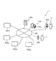
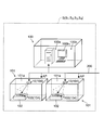
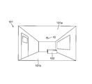
- FIG. 1 is an explanatory diagram illustrating a schematic configuration of a care support system according to an embodiment of the present invention. It is an explanatory view showing typically composition of the above-mentioned care support system in one care facility. It is explanatory drawing which shows typically the state in the living room where the moving body detection unit was installed.
- FIG. 2 is a block diagram illustrating a schematic configuration of the moving object detection unit.
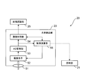
- FIG. 3 is a block diagram illustrating a detailed configuration of an optical detection unit of the moving object detection unit. It is a block diagram showing the detailed composition of the management server which manages the whole care support system. It is a block diagram showing the detailed composition of the staff terminal which the above-mentioned care support system has.
- a staff refers to a worker engaged in medical care, nursing care or nursing (eg, a doctor, a caregiver (caregiver), a nurse, etc.), and a target person supports daily life by the staff. Or a person to be cared for (care receiver, patient, etc.). Care also refers to caring for the subject with respect to medical care, nursing or nursing.
- FIG. 1 is an explanatory diagram illustrating a schematic configuration of a care support system 1 according to the present embodiment.
- the care support system 1 is a system for supporting the daily life of a cared person who lives in a nursing facility or a patient (a cared person) who is admitted to a hospital, and is also called a watching system. .
- a watching system a system for supporting the daily life of a cared person who lives in a nursing facility or a patient (a cared person) who is admitted to a hospital.
- a watching system a watching system.
- an example in which the care support system 1 is applied to a care facility will be described as an example.
- the care support system 1 interconnects the notification unit 104 (see FIG. 2) provided in each living room of the plurality of nursing homes S, the management server 110a, the staff terminal 300, and the director terminal 400 via the communication line 200. It is configured to be communicably connected to the.
- the communication line 200 includes, for example, a wired LAN (Local Area Network), a wireless LAN, an Internet line, a communication line dedicated to a mobile phone, and the like.
- FIG. 1 shows an example in which four care facilities S 1 to S 4 are connected to the management server 110a and the like via the communication line 200, but the care support system 1 of the present embodiment is applied.
- the number of the nursing homes S is not limited to the above four, but may be plural.
- the notification unit 104 is a unit that is provided in a living room in a plurality of nursing homes S and performs a notification to the outside according to the state or input operation of the cared person in the living room.
- the notification unit 104 includes at least one of the moving object detection unit 10 and the call button 103, as shown in FIG. The details of the notification unit 104 will be described later.
- the management server 110a is a server on the network that manages the entire care support system 1, and is also called a cloud server.
- Management server 110a manages a notification from the notifying unit 104 in each care facilities S, it is possible to display a notification of the content received from the notification unit 104 to the display unit 110b 1.
- the administrator of the system can look at the information displayed on the display unit 110b 1, to grasp the human subject a state in each care facilities S (e.g. whether or respiratory condition of a fall).
- Display unit 110b 1 may be a personal computer 110b displays that are communicably connected to for example a management server 110a.
- the management server 110a may be configured integrally with the personal computer 110b.
- the staff terminal 300 is a terminal device owned by the staff T who cares for the cared person, and is composed of, for example, a multifunctional portable terminal such as a tablet or a smartphone, or a notebook personal computer. Since the staff T owns the staff terminal 300, the staff T displays information provided from the director terminal 400 on the staff terminal 300 and acts based on the information, or operates the staff terminal 300 to operate the management server 100a. , It is possible to acquire various information (for example, vital information of a cared person).
- the director terminal 400 is a terminal device operated by the director D and, like the staff terminal 300, is configured by a multifunctional mobile terminal such as a tablet or a smartphone, or a notebook personal computer.
- the director D supervises and supervises at least one staff T, that is, instructs the staff T on care of the cared person and work other than care (for example, replenishing equipment, cleaning the room, etc.)
- the director (supervisor) who gives advice and is also called the care director.
- the director D operates the director terminal 400 and inputs information
- the information is transmitted from the director terminal 400 to the staff terminal 300 via the communication line 200.
- the staff T can perform an appropriate operation based on the displayed information.
- the director terminal 400 is communicably connected to the management server 110a via the communication line 200. Accordingly, the director D can operate the director terminal 400 to set and change the operation of the management server 110a, and can access the management server 110a to obtain information managed therein.
- FIG. 2 schematically shows the configuration of the care support system 1 in one care facility S.
- a staff station 100 and a living room 101 are provided in the nursing facility S.
- the staff station 100 is a so-called stuffing place for the staff T who supports the life of the care receiver who is living in the living room 101.
- the staff station 100 is provided with a management server 100a.
- the management server 100a is communicably connected to a later-described moving object detection unit 10 installed in the living room 101 via a communication line 200, and includes a central processing unit (CPU). .
- CPU central processing unit
- the management server 100a transmits various kinds of information (for example, a captured image in the living room 101 and biological information of a cared person (for example, detection information such as vital data indicating a respiratory state) output from the moving body detection unit 10 via the communication line 200. ) Is received and managed, and the received information is displayed on the display unit 100b 1.
- the manager of the nursing facility S can view the information displayed on the display unit 100b 1.
- Te can. display unit 100b 1 to grasp the state of the care (for example whether or respiratory condition of the fall), it can be configured with a display of a personal computer 100b are communicably connected to for example a management server 100a
- the management server 100a may be configured integrally with the personal computer 100b. .
- the communication line 200 is connected to an access point AP (for example, a beacon) that can communicate with the staff terminal 300 owned by the staff T (see FIG. 1).
- the access point AP is installed in the nursing home S, for example, corresponding to each living room 101.
- the management server 100a determines whether the staff T who owns the staff terminal 300 has approached the access point AP, that is, the position of the staff T, based on the radio wave intensity between the access point AP and the staff terminal 300. Can be recognized.
- the access point AP may be installed in common in the plurality of living rooms 101.
- At least one living room 101 is provided in the nursing home S, and FIG. 2 shows a case where two living rooms 101 are provided as an example.
- the living room 101 one bed 102 used by the care receiver is installed.
- the living room 101 is assumed to be a single room here, but may be a multi-bed room such as a double room or a quadruple room.
- the beds 102 are provided by the number of care receivers who spend time in the living room 101.
- a call button 103 is provided.
- the call button 103 is an operation unit that outputs (notifies) a call signal for calling the staff T who takes care of the cared person to the outside in response to an input operation of the cared person, and is connected to the communication line 200.
- the call signal is transmitted through the communication line 200 to the management server 100a or the management server 110a (hereinafter, also referred to as the management server 100a).
- the director terminal 400 can transmit instruction information (for example, work information described later) to the staff terminal 300.
- the care receiver usually presses the call button 103 at the time of his / her abnormality (when he / she wants to ask for the help of the staff T). Therefore, the call button 103 forms a notification unit 104 that notifies the care server 100a and the like of a signal indicating an abnormality of the care receiver from the room 101 of the care receiver.
- the term “abnormal” broadly indicates that the state of the body of the cared person is different from the normal state (unsteady state).
- FIG. 3 is an explanatory view schematically showing a state in the living room 101 in which the moving body detection unit 10 is installed.
- the moving body detection unit 10 is installed on the ceiling 101 a of each living room 101 and is communicably connected to the communication line 200.
- the moving object detection units 10 are installed by the number corresponding to the beds 102 in the living room 101.
- the details of the moving object detection unit 10 will be described.
- FIG. 4 is a block diagram illustrating a schematic configuration of the moving object detection unit 10.
- the moving body detection unit 10 is a non-contact sensor that is installed in the care receiver's living room 101 and detects the state (for example, physical condition) of the care receiver in the living room 101 without contact with the care receiver.
- the moving body detection unit 10 detects an abnormality in the state of the care receiver and outputs the information (detection information, detection signal) to the management server 100a and the like. Therefore, similarly to the above-mentioned call button 103, the moving object detection unit 10 also constitutes a notification unit 104 for notifying the management server 100a or the like of a signal indicating an abnormality of the care receiver from the room 101 of the care receiver.
- abnormality includes, in addition to the fall of the cared person, for example, behavior of the cared person not seen in a steady state, such as rising from a bed a predetermined number of times or more in a short time in which abdominal pain is assumed. The state is also included.
- the moving object detection unit 10 includes an image recognition system 20, a radio wave detection unit 30, and a unit control unit 40.
- the moving object detection unit 10 is also called a sensor box because it includes various sensors such as the optical detection unit 23 described below, in addition to the radio wave detection unit 30.
- the radio wave detection unit 30 is a sensor that detects the state of the care receiver in the living room 101 by emitting and receiving radio waves.
- the radio wave detecting unit 30 includes a radiating unit and a receiving unit (not shown).
- a microwave Doppler sensor that radiates a microwave in the 24 GHz band and receives a reflected wave that is reflected by the care receiver and is Doppler shifted is received. Be composed.
- the radio wave detecting unit 30 can detect the care recipient's respiratory state (respiratory rate), sleep state, heart rate, and the like as biological information (vital data) from the received reflected waves.
- the radio wave detection unit 30 functions as a micro-body motion detection unit that detects micro-body motion of the care receiver (examinee).
- the radio wave detection unit 30 emits a radio wave (microwave) and compares the frequency of the radio wave (reflected wave) reflected by the care receiver with the frequency of the emitted radio wave, thereby detecting the care receiver's frequency. It can also detect body movements (body movements). Note that the radio wave detection unit 30 may be a sensor that detects only one of body movement and minute body movement.
- the unit control unit 40 controls the operations of the image recognition system 20 and the radio wave detection unit 30, performs image processing and signal processing on the information obtained from the image recognition system 20 and the radio wave detection unit 30, and obtains the obtained result. Is output to the management server 100a as information on the state of the cared person.
- the unit control unit 40 includes a main control unit 41, an information processing unit 42, an interface unit 43, a storage unit 24, and an image recognition unit 25.
- the storage unit 24 and the image recognition unit 25 are provided in the unit control unit 40 here, but may be provided independently of the unit control unit 40. The details of the storage unit 24 and the image recognition unit 25 will be described later.
- the main control unit 41 is configured by a CPU that controls the operation of each unit in the moving object detection unit 10.
- the information processing unit 42 and the image recognizing unit 25 may be constituted by the above-mentioned CPU (may be integrated with the main control unit 41), or may be another arithmetic unit or a circuit that performs a specific process. It may be configured.
- the information processing unit 42 performs predetermined processing on information (for example, image data) output from an optical detection unit 23 (to be described later) of the image recognition system 20 and information (for example, data on a respiratory state) output from the radio wave detection unit 30. Signal processing based on the above algorithm. Information obtained by the signal processing is used for image recognition in the image recognition system 20 (particularly, the image recognition unit 25).
- a network cable (not shown) of the communication line 200 is electrically connected to the interface unit 43.
- Information on the state of the care receiver detected by the moving body detection unit 10 based on the image or the microwave is transmitted to the management server 100a via the interface unit 43 and the communication line 200.
- the image recognition system 20 includes an illumination unit 21, an illumination control unit 22, and an optical detection unit 23.
- the illumination unit 21 is configured to include an LED (Light Emitting Diode) that emits infrared light (for example, near-infrared light) so as to enable imaging in the dark, and is located on the ceiling 101 a of the living room 101.
- the interior of the living room 101 is illuminated.
- the illumination unit 21 has a plurality of LEDs, and illuminates a floor surface 101b (see FIG. 3) in the living room 101 or a wall connecting the ceiling 101a and the floor surface 101b.
- the control of illumination (infrared light emission) by the illumination unit 21 is performed by the illumination control unit 22.
- the optical detection unit 23 is an imaging unit that captures an image by capturing the inside of the living room 101 under the illumination of the illumination unit 21, and particularly captures an infrared image by capturing a care recipient in the living room 101. It is an infrared image sensor.
- the information (image data) of the image in the living room 101 acquired by the optical detection unit 23 is temporarily stored in a storage unit 24 described later, and then transmitted to the management server 100a based on a transmission request from the management server 100a, for example. Sent.
- the detailed configuration of the optical detection unit 23 is as follows.
- FIG. 5 is a block diagram showing a detailed configuration of the optical detection unit 23.
- the optical detection unit 23 is disposed adjacent to the illumination unit 21 on the ceiling 101a of the living room 101, and acquires an image of a viewpoint directly above the viewing direction by shooting.
- the optical detector 23 includes a lens 51, an image sensor 52, an AD (analog / digital) converter 53, an image processor 54, and a control calculator 55.
- the lens 51 is, for example, a fixed focus lens, and is configured by a general super wide angle lens or a fisheye lens.
- a lens having a diagonal angle of view of 150 ° or more can be used. This makes it possible to photograph the interior of the living room 101 from the ceiling 101a toward the floor 101b.
- the imaging element 52 is configured by an image sensor such as a CCD (Charge Coupled Device) or a CMOS (Complementary Metal Oxide Semiconductor).
- the image sensor 52 is configured by removing the IR cut filter so that the state of the care receiver can be detected as an image even in a completely dark environment.
- the output signal from the image sensor 52 is input to the AD converter 53.
- the A / D converter 53 receives an analog image signal of an image captured by the image sensor 52 and converts the analog image signal into a digital image signal.
- the digital image signal output from the AD conversion unit 53 is input to the image processing unit 54.
- the image processing unit 54 receives the digital image signal output from the AD conversion unit 53, and performs image processing such as black correction, noise correction, color interpolation, and white balance on the digital image signal. .
- the image-processed signal output from the image processing unit 54 is input to the image recognition unit 25.
- the control operation unit 55 executes, for example, an operation such as AE (Automatic ⁇ ⁇ Exposure) relating to the control of the image sensor 52 and controls the image sensor 52 such as exposure time and gain.
- the control calculation unit 55 executes calculations such as light amount setting and light distribution setting suitable for the illumination unit 21 as necessary, and also executes control. Note that the control operation unit 55 may have the function of the illumination control unit 22 described above.
- the image recognition system 20 further includes the storage unit 24 and the image recognition unit 25 described above.
- the storage unit 24 is a memory that stores a control program executed by the unit control unit 40 and various types of information, and includes, for example, a random access memory (RAM), a read only memory (ROM), and a nonvolatile memory.
- RAM random access memory
- ROM read only memory
- the image recognition unit 25 performs an image recognition process on the image data of the image acquired by the optical detection unit 23. More specifically, the image recognizing unit 25 extracts, for example, a contour of a target object from the image data after the image processing unit 54 of the optical detection unit 23 has performed the image processing by using a method such as pattern matching. An image recognition process for recognizing a shape is executed. Thereby, the image recognition unit 25 can recognize the state of the care receiver in the living room 101. As the state of the care receiver in the living room 101, wake-up, leaving the bed, entering (bed-down), falling down, and the like can be assumed.
- the image recognizing unit 25 can recognize the shape of the human head by pattern matching or the like, whereby the number of humans present in the living room 101 (particularly whether or not there is a plurality of humans in the living room 101). Can be detected (understood).
- the moving object detection unit 10 further includes a voice input / output unit 26.
- the voice input / output unit 26 is configured to include a microphone and a speaker. When a voice uttered by the care receiver is input to the microphone, the voice information is output to the outside. The audio information input to the moving object detection unit 10 from the outside is output from a speaker. Therefore, the care receiver in the living room 101 can make a voice call with the staff T via the moving object detection unit 10 (the voice input / output unit 26) and the staff terminal 300.
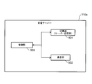
- FIG. 6 is a block diagram illustrating a detailed configuration of the management server 110a.
- the management server 110a includes a storage unit 501, a communication unit 502, and a control unit 503.
- the storage unit 501 is formed of, for example, a hard disk, and stores various information transmitted from the moving body detection unit 10 and an operation program executed by the control unit 503.
- the various types of information include, for example, biological information (vital) such as body movement (including movement, the number of movements per unit time, and the amount of movement), minute body movement (respiration rate), blood pressure, and sleep state of the care receiver. Data), image information obtained by photographing by the optical detection unit 23, an image recognition result by the image recognition unit 25, and the like.
- biological information such as body movement (including movement, the number of movements per unit time, and the amount of movement), minute body movement (respiration rate), blood pressure, and sleep state of the care receiver. Data
- image information obtained by photographing by the optical detection unit 23, an image recognition result by the image recognition unit 25, and the like In the past, as the record information (care record information) on the care of the cared person by the staff T, information such as the body temperature of the cared person and the state of eating a meal is input at the staff terminal 300
- such information is also stored in the storage unit 501.
- the various types of information may be transmitted from the moving object detection unit 10 to the management server 110a in response to an information transmission request from the management server 110a (for example, the control unit 503), or may be automatically transmitted from the moving object detection unit 10 to the management server 110a. It may be transmitted to the management server 110a.
- the storage unit 501 also stores information on the date and time when the call button 103 is pressed. Therefore, it can be said that the storage unit 501 constitutes a server storage unit that stores the contents of the notification from the past notification unit 104 (the motion detection unit 10 and the call button 103) regarding the care receiver. As described above, since the management server 110a includes the storage unit 501, the notification from the notification unit 104 can be managed by the management server 110a.
- the communication unit 502 is a communication interface with the outside, and includes a transmission circuit, a reception circuit, a modulation circuit, a demodulation circuit, an antenna, and the like as necessary in addition to the input / output ports.
- the control unit 503 includes a CPU that controls the operation of each unit of the management server 110a, and operates according to an operation program stored in the storage unit 501.
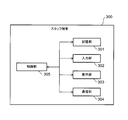
- FIG. 7 is a block diagram showing a detailed configuration of the staff terminal 300.
- the staff terminal 300 includes a storage unit 301, an input unit 302, a display unit 303, a communication unit 304, and a control unit 305.
- the storage unit 301 is a memory that stores an operation program executed by the control unit 305 and various types of information, and includes, for example, a RAM, a ROM, and a nonvolatile memory.
- the input unit 302 includes a touch panel input device that receives an input operation by the staff T.
- the display unit 303 is a device that displays various types of information, for example, is configured by a liquid crystal display device, and is configured integrally with the input unit 302.
- the communication unit 304 is a communication interface with the outside, and includes a transmission circuit, a reception circuit, an antenna, and the like.
- the control unit 305 is configured by a CPU that controls the operation of each unit of the staff terminal 300, and operates according to the operation program stored in the storage unit 301.
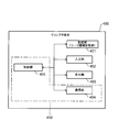
- FIG. 8 is a block diagram showing a detailed configuration of director terminal 400.
- the director terminal 400 includes a storage unit 401, an input unit 402, a display unit 403, a communication unit 404, and a control unit 405.
- the storage unit 401 is a memory that stores an operation program executed by the control unit 405 and various types of information, and includes, for example, a RAM, a ROM, a nonvolatile memory, and a hard disk.
- the storage unit 401 forms a work information storage unit that stores work information.
- the above-mentioned work information is information indicating how the staff T responds to the notification, which is output from the director terminal 400 to the staff terminal 300 when the notification unit 104 notifies the management server 110a or the director terminal 400. is there.
- This work information includes common work information indicating a coping method common among the plurality of nursing homes S.
- the staff T operates the staff terminal 300 to communicate with the moving body detection unit 10 in the room 101 of the care receiver. Make a voice call with the cared person (call to the cared person); (2) rush to the cared person's living room 101 after making the call; It is possible to rush to 101 immediately.
- information indicating any one of the above-mentioned (1) to (3) is stored in the storage unit 401 as common work information.
- the input unit 402 is a device that receives an input operation by the director D.
- the input unit 402 includes a keyboard, a mouse, and a touch pad when the director terminal 400 is configured by a personal computer, and includes a touch panel input device when the director terminal 400 is configured by a smartphone or the like.
- the input unit 402 functions as an operation unit that receives the input of the work information by the director D.
- the display unit 403 is a device that displays various types of information, and includes, for example, a liquid crystal display device.
- the communication unit 404 is a communication interface with the outside, and includes a transmission circuit, a reception circuit, an antenna, and the like as necessary in addition to the input / output ports.
- the control unit 405 is configured by a CPU that controls the operation of each unit of the director terminal 400, and operates according to the operation program stored in the storage unit 401.
- the control unit 405 receives the notification generation signal from the management server 110a, the control unit 405 reads the work information from the storage unit 401 and outputs the work information from the communication unit 404 to the staff terminal 300. Therefore, the control unit 405 and the communication unit 404 constitute a work information output unit 410 that reads out the work information from the storage unit 401 and outputs the work information to the staff terminal 300 when receiving the notification generation signal.
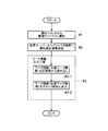
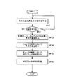
- FIG. 9 is a flowchart showing a flow of processing by the information providing method.
- the information providing method of the present embodiment includes a notification step (# 1), a notification signal transmission step (# 2), and a work information output step (# 3).
- a notification is sent from the notification unit 104 to the outside according to the state of the care receiver in the living room 101 or the input operation of the care receiver. That is, when the moving object detection unit 10 detects the state of the care receiver (for example, falling), a detection signal corresponding to the state is notified to the outside. When the care receiver presses the call button 103, a call signal corresponding to the pressing operation is notified to the outside.
- the “external” described above may be, for example, the management server 110a, but may be the director terminal 400. In the latter case, the next notification signal transmission step of # 2 can be omitted.
- the notification signal transmitting step when the management server 110a receives a notification from the notification unit 104, the control unit 503 of the management server 110a transmits a notification generation signal to the director terminal 400 via the communication unit 502.
- the director terminal 400 can execute the next work information output step with the reception of the notification generation signal as a trigger.
- control unit 405 of director terminal 400 may display on display unit 403 that the notification generation signal has been received. In this case, it is possible to notify the director D of the notification from the notification unit 104 and make the director D recognize it.
- the director terminal 400 In the work information output step, after the director terminal 400 receives the notification generation signal from the management server 110a, the director terminal 400 outputs, to the staff terminal 300, work information indicating how the staff T responds to the notification. That is, when the director terminal 400 receives the notification generation signal from the management server 110a, the control unit 405 reads work information (for example, common work information) from the storage unit 401 (# 3-1; work reading step). Then, the control unit 405 outputs the work information read from the storage unit 401 to the staff terminal 300 via the communication unit 404 (# 3-2; information providing step).
- work information for example, common work information
- the control unit 305 can display the work information (common work information) on the display unit 303 and present a coping method to the notification to the staff T. It is possible to cope according to the method.
- the director terminal 400 directly receives the notification from the notification unit 104
- the director terminal 400 reads the work information (common work information) from the storage unit 401 after receiving the notification, and sends the work information (common work information) to the staff terminal 300. Just output it.
- the work information output from the director terminal 400 to the staff terminal 300 includes a common work indicating a common coping method among a plurality of nursing facilities S 1 to S 4. Since the information is included, the staff T responds to the notification from the notification unit 104 in the facility based on the common work information, regardless of which of the multiple nursing facilities S 1 to S 4 works. Common measures can be taken. For example, if the common work information is “call out to the cared person”, the notification from the notification unit 104 can be used when the staff T works in any of the multiple nursing facilities S 1 to S 4. On the other hand, it is only necessary to call out to the care receiver uniformly.
- the staff T can work at the same burden level regardless of the nursing homes S 1 to S 4 , and the burden on the staff T is biased due to differences in the working facilities. Can be reduced. Therefore, the staff T does not shy away from recruiting human resources at a plurality of nursing homes S 1 to S 4 to work at a facility with a large burden, and it is necessary that the staff T apply for work at any facility. Can be expected. As a result, it is possible to promote the hiring of human resources at any of the facilities, and to utilize human resources efficiently. Further, since the staff T can cope with the notification in any of the nursing facilities S 1 to S 4 , even if the work location changes between the nursing facilities S 1 to S 4 , the staff T is not bothered by the coping. Makes it easier to work.
- the management server 110a transmits a notification generation signal to the director terminal 400 (# 2), and the director terminal 400 receives the notification generation signal from the management server 110a. Then, the work information is output to the staff terminal 300 (# 3).
- the notification from the notification unit 104 may be directly output to the director terminal 400.
- the reception of a notification generation signal transmitted from the management server 110a is used as a trigger to set the notification. Work information can be output from the terminal 400 to the staff terminal 300.
- the director terminal 400 reads out the work information from the storage unit 401 and outputs the work information to the staff terminal 300 when the notification generation signal is received from the management server 110a. And a work information output unit 410 (control unit 405, communication unit 404).
- the director terminal 400 automatically reads the work information from the storage unit 401 and automatically outputs the work information to the staff terminal 300. Work information can be promptly output to the staff terminal 300 without waiting for an input instruction by D, and the staff T can promptly respond to the notification from the notification unit 104.
- the director D can input the work information in advance by operating the input unit 402 and store the work information in the storage unit 401.
- the notification unit 104 includes the moving object detection unit 10 that detects the state of the care receiver in the living room 101 and notifies the detection information to the outside. Even in a configuration in which the detection information is notified to the outside from the moving object detection unit 10, the director terminal 400 outputs the work information (particularly, common work information) to the staff terminal 300, so that the staff T is different depending on the working facility. It is possible to obtain the effect of the present embodiment described above, which can reduce the occurrence of bias in the load of the above.
- the notification unit 104 includes a call button 103 for notifying a call signal for calling the staff T to the outside in accordance with an input operation of the care receiver in the living room 101. Even in the configuration in which the call signal is notified from the call button 103 to the outside, the director terminal 400 outputs the work information (particularly, common work information) to the staff terminal 300, so that the staff T depends on the difference of the working facilities. It is possible to obtain the effect of the above-described present embodiment that the occurrence of bias in the load can be reduced.
- the work information described above further includes supplementary work information that supplements a coping method (common work information) for the notification. May be included.
- supplementary work information may be added to the common work information and output from the director terminal 400 to the staff terminal 300.
- the complementary work information of the specific cared person may be "rush to the cared person after the calling.” Is set.
- Such complementary work information is input by the input unit 402 and is stored in the storage unit 401 in advance as information corresponding to the care receiver.
- the details of the information providing method performed using the work information including the complementary work information will be described.
- FIG. 10 is a flowchart showing a flow of processing according to an example other than the information providing method in the care support system 1 of the present embodiment.
- the notification step # 1 when a notification according to the state of the care receiver in the living room 101 or the input operation of the care receiver is performed from the notification unit 104 to the management server 110a, the control unit 503 of the management server 110a Then, it is determined whether or not the notification is a notification indicating that the care receiver is in an abnormal state (# 1-1).
- the control unit 503 sets the notification It is determined that the notification from the unit 104 (the call button 103) is a notification indicating that the care receiver is in an abnormal state.
- the control unit 405 transmits to the director terminal 400 a first notification generation signal indicating that the notification (notification indicating that the care receiver is in an abnormal state) has occurred (# 2- 1: notification signal generation step).
- the control unit 503 indicates that the notification indicates an abnormal state of the care receiver. It is determined that the notification is not a notification (a notification indicating a steady state). In this case, the control unit 405 transmits to the director terminal 400 a second notification generation signal indicating that a notification indicating that the care receiver is in a steady state has been generated (# 2-2; notification signal). Generating step).
- processing corresponding to the type of the notification generation signal received by the director terminal 400 from the management server 110a is performed. That is, when the director terminal 400 receives the first notification generation signal from the management server 110a, the control unit 405 reads the common work information and the complementary work information as the work information from the storage unit 401 (# 3-1-1; Work information reading step). Then, the control unit 405 outputs the work information read from the storage unit 401 to the staff terminal 300 via the communication unit 404 (# 3-2-1; information providing step). Accordingly, in the staff terminal 300, for example, the control unit 305 can display the work information (common work information and supplementary work information) on the display unit 303, and can present a coping method to the notification to the staff T.
- the control unit 305 can display the work information (common work information and supplementary work information) on the display unit 303, and can present a coping method to the notification to the staff T.
- the control unit 405 reads only the common work information from the storage unit 401 as the work information (# 3-1-2; read the work information). Process). Then, the control unit 405 outputs the work information (common work information) read from the storage unit 401 to the staff terminal 300 via the communication unit 404 (# 3-2-2; information providing step). Accordingly, in the staff terminal 300, for example, the control unit 305 can display the work information (common work information) on the display unit 303 and present a coping method to the notification to the staff T. It is possible to cope according to the method. For example, if “calling to the care receiver” is set as the common work information, the staff T executes only the calling in response to the notification from the notification unit 104.
- the management server 110a when the notification from the notification unit 104 is a notification indicating that the care receiver is in an abnormal state, the management server 110a outputs the first notification generation signal to the director terminal 400. If the notification from the notification unit 014 is a notification indicating that the care receiver is in a steady state, a second notification generation signal is output to the director terminal 400 (# 1-1, # 2-1). , # 2-2). Then, when the work information output unit 410 (control unit 405, communication unit 404) of the director terminal 400 receives the first notification generation signal from the management server 110a, the work information output unit 410 reads the common work information and the complementary work information from the storage unit 401. Is read out and output to the staff terminal 300.
- the common work information is read out from the storage unit 401 and output to the staff terminal 300 (# 3-1-1). 1, # 3-2-1, # 3-1-2, # 3-2-2).
- the director D operates the input unit 402 to input the supplementary work information regarding the care receiver, and stores the information in the storage unit 401 in advance. , In preparation for the future occurrence of the notification.
- the supplementary work information is stored in the storage unit 401 based on the prediction of the occurrence of the future notification.
- FIG. 11 is a block diagram schematically showing another configuration of the management server 110a of the care support system 1 of the present embodiment.
- the management server 110a further includes a prediction determination unit 504 in addition to the configuration shown in FIG.
- the prediction determination unit 504 predicts the possibility that a notification indicating that the care receiver is in an abnormal state will be generated from the notification unit 104 in the future based on the information stored in the storage unit 501.
- Such a prediction determination unit 504 is configured by the same or a separate CPU as the control unit 503.
- the information stored in the storage unit 501 can be, for example, the number of times a call signal is received by the call button 103 in a predetermined period, care record information, and the like.
- the management server 110a includes a prediction information output unit 510.
- the prediction information output unit 510 includes a control unit 503 and a communication unit 502.
- the control unit 503 transmits the notification to the director terminal 400.
- Predictive information indicating that there is a possibility of notification is output via the communication unit 502.
- FIG. 12 is a flowchart showing a flow of a process of causing the director terminal 400 to store the supplementary work information in the storage unit 401.
- the prediction determining unit 504 of the management server 110a is configured to perform at least one of past notification contents (for example, the number of times a call signal has been received within a predetermined period in the past) and past care record information stored in the storage unit 501. Then, it is predicted whether or not there is a possibility that a notification of a call signal from the call button 103 will be generated by an input operation of the cared person in the future (# 11; prediction determination step).
- the control unit 503 makes a prediction to the director terminal 400 indicating that there is a possibility of occurrence of a notification.
- the information is output via the communication unit 502 (# 13; prediction information output step).
- the process returns to # 11, and the prediction determination unit 504 continues to predict the possibility.
- FIG. 13 shows an example of a display screen of the display unit 403 of the director terminal 400.
- the display unit 403 displays supplementary work information to be presented from the director terminal 400 to the staff terminal 300 when the call signal is actually notified to the director D. You will be prompted for input.
- the prediction determination unit 504 of the management server 110a determines the content of the notification from the past call button 103 regarding the care receiver and the care input in the past regarding the care of the care receiver stored in the storage unit 501. Based on at least one of the record information, it is predicted that a notification of a call signal from the call button 103 (a notification indicating that the care receiver is in an abnormal state) will occur in the future (# 11). Then, when it is predicted that there is a possibility that a notification will occur, the management server 100a outputs prediction information to the director terminal 400 (# 12, # 13), and the director terminal 400 displays the prediction information. Is performed (# 14).
- the director D can preliminarily determine and input the supplementary work information to be presented to the staff T when actually notified. Therefore, the supplementary work information can be promptly presented to the staff terminal 300 after the notification is actually received, and the staff T can be promptly dealt with.
- the method of predicting the possibility that a notification indicating that the care receiver is in an abnormal state will occur in the future is not limited to the above example.
- the storage unit 501 stores the detection information output from the moving object detection unit 10, and the prediction determination unit 504 determines at least a notification of a call signal and a notification of detection information indicating an abnormality based on the detection information. Whether or not one of them may occur may be predicted.
- the cared person has broken his stomach and started up many times in the past in a short time because of a toilet
- the past detection information for example, the detection information that the user has started up many times in a short time by image recognition
- the director D can actually receive a notification based on the displayed prediction information.
- the supplementary work information to be presented to the staff T can be determined in advance.
- the storage unit 501 stores at least one of the contents of the notification from the past notification unit 104 (the call button 103 and the moving body detection unit 10) regarding the care receiver and the care record information input in the past regarding the care of the care receiver. Can be said to be stored. Then, the prediction determination unit 504 is based on at least one of the contents of the notification of the care receiver in the past from the notification unit 104 and the care record information input in the past regarding the care of the care receiver stored in the storage unit 501. Thus, it can be said that the possibility that a notification indicating that the care receiver is in an abnormal state from the notification unit 104 will be generated in the future.
- the care support system 1 is applied to a plurality of nursing facilities, but it is of course applicable to a plurality of medical institutions such as hospitals and clinics.
- the care support system of the present embodiment is a care support system that supports the daily life of the target person, and is provided in each living room of a plurality of facilities, and according to the state or the input operation of the target person in the living room.
- a notification unit that sends a notification to the outside, and a director that outputs work information indicating a method of responding to the notification to a staff terminal owned by staff who cares for the target person based on the notification from the notification unit.
- a work terminal, and the work information includes common work information indicating a coping method common among the plurality of facilities.
- the above care support system further includes a management server that manages the notification from the notification unit of the plurality of facilities, and the management server notifies the director terminal when receiving the notification from the notification unit. After transmitting a generation signal, the director terminal may output the work information to the staff terminal after receiving the notification generation signal from the management server.
- the director terminal stores the work information including the common work information in advance, and the work information storage unit when the notification generation signal is received from the management server.
- a work information output unit for reading the work information from the staff terminal and outputting the work information to the staff terminal.
- the work information may further include complementary work information that complements the coping method when the subject is in an abnormal state.
- the management server sends a first notification generation signal to the director terminal when the notification from the notification unit is a notification indicating that the subject is in an abnormal state.
- a second notification generation signal is output to the director terminal, and A work information output unit that, when receiving the first notification generation signal from the management server, reads out the common work information and the complementary work information from the work information storage unit and outputs them to the staff terminal;
- the common work information is read from the work information storage unit. It may be output to the staff terminal in.
- the management server is a server storage unit that stores at least one of contents of a notification from the notification unit in the past regarding the subject and care record information input in the past regarding care of the subject. And, based on information stored in the server storage unit, a prediction determination unit that predicts a possibility that a notification indicating that the subject is in an abnormal state will occur from the notification unit in the future, and the prediction determination unit.
- a prediction information output unit that outputs prediction information indicating that a notification may be generated to the director terminal, when it is predicted that the notification may be generated, and the director terminal includes: And a display unit for displaying the prediction information.
- the director terminal may further include an input unit that receives an input operation of the work information.
- the notification unit may include a detection unit that detects a state of the subject in the living room and notifies detection information to the outside.
- the notification unit may include an operation unit that notifies a call signal for calling the staff to the outside in response to an input operation of the subject in the living room.
- the information providing method is an information providing method in a care support system that supports a subject's daily life, and includes a notification unit provided in a living room in a plurality of facilities.
- the information providing method further includes a notification generation signal transmitting step of transmitting a notification generation signal to the director terminal when the management server receives the notification from the notification unit. After the terminal receives the notification generation signal from the management server, the work information may be output to the staff terminal.
- the work information output step includes: when receiving the notification generation signal from the management server, reading the work information from a work information storage unit; and reading the read work information. Providing an information to the staff terminal.
- the work information may further include complementary work information that complements the coping method when the subject is in an abnormal state.
- the notification generation signal transmitting step if the notification from the notification unit is a notification indicating that the subject is in an abnormal state, the first notification generation signal is While outputting to the director terminal, if the notification from the notification unit is a notification indicating that the subject is in a steady state, a second notification generation signal is output to the director terminal, and the work
- the common work information and the supplementary work information are read from the work information storage unit and output to the staff terminal
- the common work information is read from the work information storage unit and It may be output to full terminal.
- the information providing method described above includes storing, in the server storage unit of the management server, at least the content of the notification from the notification unit in the past regarding the subject and the care record information input in the past regarding the care of the subject.
- the method may include a prediction information output step of outputting prediction information indicating that a notification may be generated to the director terminal, and a prediction information display step of displaying the prediction information on the director terminal.
- the present invention is applicable to, for example, a care support system that supports the daily life of a cared person in a nursing home or a patient in a hospital.
Landscapes
- Health & Medical Sciences (AREA)
- Engineering & Computer Science (AREA)
- Business, Economics & Management (AREA)
- Biomedical Technology (AREA)
- Primary Health Care (AREA)
- General Health & Medical Sciences (AREA)
- Tourism & Hospitality (AREA)
- General Business, Economics & Management (AREA)
- General Physics & Mathematics (AREA)
- Strategic Management (AREA)
- Physics & Mathematics (AREA)
- Marketing (AREA)
- Economics (AREA)
- Human Resources & Organizations (AREA)
- Theoretical Computer Science (AREA)
- Child & Adolescent Psychology (AREA)
- Epidemiology (AREA)
- Medical Informatics (AREA)
- Public Health (AREA)
- Alarm Systems (AREA)
- Medical Treatment And Welfare Office Work (AREA)
Abstract
対象者の日常の生活を支援するケアサポートシステム(1)は、通知ユニットと、ディレクタ端末(400)とを備える。通知ユニットは、複数の施設のそれぞれの居室に設けられ、居室内の対象者の状態または入力操作に応じた通知を外部に行う。ディレクタ端末(400)は、通知ユニットからの通知に基づいて、対象者を世話するスタッフが所有するスタッフ端末に対して、通知に対する対処方法を示すワーク情報を出力する。ワーク情報は、複数の施設間で共通する対処方法を示す共通ワーク情報を含む。
Description
本発明は、対象者の日常の生活を支援するケアサポートシステムと、そのケアサポートシステムにおける情報提供方法とに関する。
従来から、医療機関や介護施設に適用され、居室内の患者や被介護者(これらをまとめて(監視の)対象者とも称する)を監視するシステムが提案されている。例えば特許文献1のシステムでは、居室内に設置された検知ユニットが、対象者の所定の行動を検知し、画像を生成し、音声を送受信する機能を有しており、管理サーバーユニットが、検知ユニットから送信される検知結果(監視情報)を管理し、スタッフが所有する端末ユニットが、管理サーバーユニットから送信される監視情報を受信して表示し、音声を送受信する機能を有している。このシステムでは、スタッフは、携帯端末ユニットを例えば声かけモードで動作させ、携帯端末ユニットおよび検知ユニットを介して対象者と通話して、対象者の状態を音声で確認することが可能である。
ところで、近年、介護施設では、正社員のほか、非正規社員がスタッフとして勤務する形態が増えている。ここで、正社員とは、期間の定めのない雇用契約で働く人を指す。これに対して、非正規社員とは、パート、契約、派遣、請負といった雇用形態で働く人を指す。非正規社員は、例えば、勤務地、勤務時間、報酬などに関する希望の条件を予め派遣会社に提示しておき、派遣会社から希望の条件に合致した介護施設が紹介されることで、自分の希望に合う介護施設で働くことができる。このため、非正規社員は、雇用契約によっては、例えば、本日は介護施設Aで勤務し、明日は介護施設Bで勤務する、という勤務形態が可能となる。
一方、介護施設内に構築されるシステムの運用の仕方については、介護施設の管理者(事業者)が独自で設定することができるが、近年の経営の効率化を目的とする事業者の統廃合により、1つの事業者が複数の介護施設を管理する形態が増えている。このとき、複数の介護施設のシステムの運用が(統廃合前の設定により)まちまちであると、複数の介護施設間でスタッフの負担に偏りが生じる。例えば、居室内の検知ユニットからの通知があったときに、介護施設Aでは、スタッフは携帯端末を介して対象者に対して声かけだけを行えばよいのに対して、介護施設Bでは、対象者のもとに駆け付けなければならない場合、介護施設Aでの勤務よりも介護施設Bでの勤務のほうが、スタッフの負担が増大する。すると、スタッフは、介護施設Bでの勤務を今後希望しなくなる。このことは、介護施設AおよびBの今後の人材募集に対して、介護施設Bに登用する人材の停滞化を助長し、効率の良い人材活用の妨げとなる。
したがって、スタッフが複数の介護施設の中で、勤務場所を適宜選択して勤務できる形態では、複数の介護施設間でのスタッフの勤務負担の偏りを低減できるシステムを構築することが望ましい。しかし、そのようなシステムは未だ提案されていない。なお、このような問題は、介護施設のみならず、病院等の医療機関をスタッフの勤務先とする場合において、スタッフが複数の医療機関の中から勤務場所を適宜選択して勤務できる場合には、同様に起こり得る。
本発明は、上記の問題点を解決するためになされたものであり、その目的は、複数の施設間でのスタッフの勤務負担の偏りを低減し、どの施設についても人材の登用を促進することができるケアサポートシステムと、そのケアサポートシステムにおける情報提供方法とを提供することにある。
本発明の一側面に係るケアサポートシステムは、対象者の日常の生活を支援するケアサポートシステムであって、複数の施設のそれぞれの居室に設けられ、前記居室内の前記対象者の状態または入力操作に応じた通知を外部に行う通知ユニットと、前記通知ユニットからの前記通知に基づいて、前記対象者を世話するスタッフが所有するスタッフ端末に対して、前記通知に対する対処方法を示すワーク情報を出力するディレクタ端末とを備え、前記ワーク情報は、前記複数の施設間で共通する対処方法を示す共通ワーク情報を含む。
本発明の他の側面に係る情報提供方法は、対象者の日常の生活を支援するケアサポートシステムにおける情報提供方法であって、複数の施設内の居室に設けられた通知ユニットから、前記居室内の前記対象者の状態または入力操作に応じた通知を外部に行う通知工程と、前記通知ユニットからの前記通知に基づいて、ディレクタ端末から、前記対象者を世話するスタッフが所有するスタッフ端末に対して、前記通知に対する対処方法を示すワーク情報を出力するワーク情報出力工程とを含み、前記ワーク情報は、前記複数の施設間で共通する対処方法を示す共通ワーク情報を含む。
ディレクタ端末からスタッフ端末に出力されるワーク情報には、複数の施設間で共通する対処方法を示す共通ワーク情報が含まれる。これにより、スタッフは、複数の施設の中のどの施設で勤務する場合でも、上記共通ワーク情報に基づいて、共通した対処を行うことが可能となるため、複数の施設間でのスタッフの勤務負担に偏りが生じるのを低減することができる。その結果、複数の施設の人材募集に対して、どの施設についてもスタッフが勤務を応募することを期待でき、どの施設についても人材登用を促進することが可能となる。
本発明の実施の一形態について、図面に基づいて説明すれば、以下の通りである。なお、本明細書において、スタッフとは、医療、介護または看護に従事する従事者(医師、介護士(介護者)、看護師など)を指し、対象者とは、スタッフによって日常の生活を支援またはケアする対象となる者(被介護者、患者など)を指す。また、ケアとは、医療、介護または看護に関して対象者を世話することを指す。
〔ケアサポートシステムの全体構成〕
図1は、本実施形態のケアサポートシステム1の概略の構成を示す説明図である。ケアサポートシステム1は、介護施設に入居している被介護者や、病院に入院している患者(被看護者)の日常の生活を支援するためのシステムであり、見守りシステムとも呼ばれている。ここでは、例として、ケアサポートシステム1を介護施設に適用した例について説明する。
図1は、本実施形態のケアサポートシステム1の概略の構成を示す説明図である。ケアサポートシステム1は、介護施設に入居している被介護者や、病院に入院している患者(被看護者)の日常の生活を支援するためのシステムであり、見守りシステムとも呼ばれている。ここでは、例として、ケアサポートシステム1を介護施設に適用した例について説明する。
ケアサポートシステム1は、複数の介護施設Sの各居室に設けられる通知ユニット104(図2参照)と、管理サーバー110aと、スタッフ端末300と、ディレクタ端末400とを、通信回線200を介して相互に通信可能に接続して構成されている。通信回線200は、例えば有線LAN(Local Area Network)、無線LAN、インターネット回線、携帯電話の通信専用回線などを含んで構成される。なお、図1では、4つの介護施設S1~S4が通信回線200を介して管理サーバー110a等と接続されている例を示しているが、本実施形態のケアサポートシステム1が適用される介護施設Sの数は、上記の4つに限定されるわけではなく、複数であればよい。
上記の通知ユニット104は、複数の介護施設S内の居室に設けられ、居室内の被介護者の状態または入力操作に応じた通知を外部に行うユニットである。本実施形態では、通知ユニット104は、図2に示すように、動体検知ユニット10およびコールボタン103の少なくとも一方を含む。なお、通知ユニット104の詳細については後述する。
管理サーバー110aは、ケアサポートシステム1の全体を管理するネットワーク上のサーバーであり、クラウドサーバーとも呼ばれる。管理サーバー110aは、各介護施設S内の通知ユニット104からの通知を管理しており、通知ユニット104から受けた通知の内容を表示部110b1に表示させることができる。これにより、システムの管理者は、表示部110b1に表示された情報を見て、各介護施設S内の被介護者の状態(例えば転倒の有無や呼吸状態)を把握することができる。表示部110b1は、例えば管理サーバー110aと通信可能に接続されるパーソナルコンピュータ110bのディスプレイで構成することができる。なお、管理サーバー110aは、パーソナルコンピュータ110bと一体的に構成されてもよい。
スタッフ端末300は、被介護者をケアするスタッフTが所有する端末装置であり、例えばタブレットやスマートフォンなどの多機能型携帯端末、またはノート型パーソナルコンピュータで構成される。スタッフTがスタッフ端末300を所有することにより、スタッフTはディレクタ端末400から提供される情報をスタッフ端末300で表示させてその情報に基づいて行動したり、スタッフ端末300を操作して管理サーバー100aにアクセスし、種々の情報(例えば被介護者のバイタル情報)を取得することが可能となる。
ディレクタ端末400は、ディレクタDによって操作される端末装置であり、スタッフ端末300と同様に、タブレットやスマートフォンなどの多機能型携帯端末、またはノート型パーソナルコンピュータで構成される。ここで、ディレクタDとは、少なくとも1人のスタッフTを指揮監督する、つまり、スタッフTに対して、被介護者のケアやケア以外の作業(例えば備品補充、部屋の清掃など)に関する指示や助言を与える指示者(監督者)を指し、ケアディレクタとも呼ばれる。ディレクタDがディレクタ端末400を操作して情報を入力すると、その情報がディレクタ端末400から通信回線200を介してスタッフ端末300に送信される。上記情報をスタッフ端末300の画面に表示させることにより、スタッフTは、表示された情報に基づいて適切な作業を行うことができる。
また、ディレクタ端末400は、通信回線200を介して管理サーバー110aとも通信可能に接続されている。これにより、ディレクタDは、ディレクタ端末400を操作して、管理サーバー110aにおける動作の設定および変更を行ったり、管理サーバー110aにアクセスしてそこで管理されている情報を入手することが可能となる。
〔介護施設内の構成〕
図2は、1つの介護施設S内でのケアサポートシステム1の構成を模式的に示している。介護施設Sには、スタッフステーション100および居室101が設けられている。スタッフステーション100は、居室101に入居している被介護者の生活をサポートするスタッフTのいわゆる詰め所である。このスタッフステーション100には、管理サーバー100aが設けられている。管理サーバー100aは、通信回線200を介して、居室101に設置される後述の動体検知ユニット10と通信可能に接続されており、中央演算処理装置(CPU;Central Processing Unit)を含んで構成される。
図2は、1つの介護施設S内でのケアサポートシステム1の構成を模式的に示している。介護施設Sには、スタッフステーション100および居室101が設けられている。スタッフステーション100は、居室101に入居している被介護者の生活をサポートするスタッフTのいわゆる詰め所である。このスタッフステーション100には、管理サーバー100aが設けられている。管理サーバー100aは、通信回線200を介して、居室101に設置される後述の動体検知ユニット10と通信可能に接続されており、中央演算処理装置(CPU;Central Processing Unit)を含んで構成される。
管理サーバー100aは、通信回線200を介して、動体検知ユニット10から出力される各種の情報(例えば居室101内の撮影画像や被介護者の生体情報(例えば呼吸状態を示すバイタルデータなどの検知情報)を受信して管理するとともに、受信した情報を表示部100b1に表示させる。これにより、スタッフステーション100内では、例えば介護施設Sの管理者が、表示部100b1に表示された情報を見て、被介護者の状態(例えば転倒の有無や呼吸状態)を把握することができる。表示部100b1は、例えば管理サーバー100aと通信可能に接続されるパーソナルコンピュータ100bのディスプレイで構成することができる。なお、管理サーバー100aは、パーソナルコンピュータ100bと一体的に構成されてもよい。
なお、介護施設S内の管理サーバー100a、表示部100b1およびパーソナルコンピュータ100bを、図1で示したネットワーク上の管理サーバー110a、表示部110b1およびパーソナルコンピュータ110bで代用してこれらを省略した構成とすることも可能である。
通信回線200は、スタッフT(図1参照)が所有するスタッフ端末300と通信可能なアクセスポイントAP(例えばビーコン)と接続されている。アクセスポイントAPは、例えば各居室101に対応して介護施設S内に設置されている。これにより、管理サーバー100aは、アクセスポイントAPとスタッフ端末300との間の電波強度に基づいて、スタッフ端末300を所有するスタッフTが上記アクセスポイントAPに近づいたかどうか、つまり、スタッフTの位置を認識することができる。なお、アクセスポイントAPは、複数の居室101に共通して設置されていてもよい。
居室101は、介護施設Sにおいて少なくとも1つ設けられており、図2では例として居室101が2つ設けられている場合を示している。居室101内には、被介護者が使用するベッド102が1つ設置されている。なお、居室101として、ここでは1人部屋を想定しているが、2人部屋や4人部屋等の多床室であってもよい。多床室の場合、居室101内で過ごす被介護者の数だけ、ベッド102が設置される。
また、各居室101には、コールボタン103が設置されている。コールボタン103は、被介護者の入力操作に応じて、被介護者を世話するスタッフTを呼び出すための呼出信号を外部に出力(通知)する操作ユニットであり、通信回線200と接続されている。緊急時や必要なときに、被介護者がコールボタン103を操作(例えば押圧)すると、上記呼出信号が通信回線200を介して管理サーバー100aまたは管理サーバー110a(以下、管理サーバー100a等とも称する)に入力され、管理サーバー100a等からディレクタ端末400に通知が発生した旨の信号(通知発生信号)が出力される。これにより、ディレクタ端末400は、スタッフ端末300に指示情報(例えば後述するワーク情報)を送信することが可能となる。
なお、被介護者は、通常、自身の異常時(スタッフTの助けを求めたいとき)にコールボタン103を押圧する。したがって、コールボタン103は、被介護者の居室101から管理サーバー100a等に対して、被介護者の異常を示す信号を通知する通知ユニット104を構成している。なお、ここでの「異常」とは、被介護者の身体の状態が定常時とは異なる状態(非定常状態)であることを広く指す。
図3は、動体検知ユニット10が設置された居室101内の様子を模式的に示す説明図である。動体検知ユニット10は、各居室101の天井部101aに設置され、通信回線200と通信可能に接続されている。なお、居室101内に複数のベッド102が設置されている場合、動体検知ユニット10は、居室101内のベッド102に対応する数だけ設置される。以下、動体検知ユニット10の詳細について説明する。
〔動体検知ユニット〕
図4は、動体検知ユニット10の概略の構成を示すブロック図である。動体検知ユニット10は、被介護者の居室101内に設置され、居室101内の被介護者の状態(例えば身体状態)を被介護者とは非接触で検知する非接触センサである。動体検知ユニット10は、被介護者の状態の異常を検知して、その情報(検知情報、検知信号)を管理サーバー100a等に出力する。したがって、動体検知ユニット10も上記したコールボタン103と同様に、被介護者の居室101から管理サーバー100a等に被介護者の異常を示す信号を通知する通知ユニット104を構成している。なお、上記の「異常」には、被介護者の転倒のほか、例えば腹痛が想定される短時間での所定回数以上のベッドからの立ち上がりなど、定常状態では見られない被介護者の行動または状態も含まれる。
図4は、動体検知ユニット10の概略の構成を示すブロック図である。動体検知ユニット10は、被介護者の居室101内に設置され、居室101内の被介護者の状態(例えば身体状態)を被介護者とは非接触で検知する非接触センサである。動体検知ユニット10は、被介護者の状態の異常を検知して、その情報(検知情報、検知信号)を管理サーバー100a等に出力する。したがって、動体検知ユニット10も上記したコールボタン103と同様に、被介護者の居室101から管理サーバー100a等に被介護者の異常を示す信号を通知する通知ユニット104を構成している。なお、上記の「異常」には、被介護者の転倒のほか、例えば腹痛が想定される短時間での所定回数以上のベッドからの立ち上がりなど、定常状態では見られない被介護者の行動または状態も含まれる。
動体検知ユニット10は、画像認識システム20、電波検出部30およびユニット制御部40を備えている。動体検知ユニット10は、電波検出部30をはじめ、後述する光学検出部23など、種々のセンサを備えていることから、センサボックスとも呼ばれる。
(電波検出部)
電波検出部30は、電波の放射および受信によって、居室101内での被介護者の状態を検知するセンサである。電波検出部30は、不図示の放射部および受信部を備えており、例えば24GHz帯のマイクロ波を放射し、被介護者にて反射してドップラーシフトした反射波を受信するマイクロ波ドップラーセンサによって構成される。これにより、電波検出部30は、受信した反射波から、被介護者の呼吸状態(呼吸数)、睡眠状態、心拍数などを生体情報(バイタルデータ)として検出することができる。
電波検出部30は、電波の放射および受信によって、居室101内での被介護者の状態を検知するセンサである。電波検出部30は、不図示の放射部および受信部を備えており、例えば24GHz帯のマイクロ波を放射し、被介護者にて反射してドップラーシフトした反射波を受信するマイクロ波ドップラーセンサによって構成される。これにより、電波検出部30は、受信した反射波から、被介護者の呼吸状態(呼吸数)、睡眠状態、心拍数などを生体情報(バイタルデータ)として検出することができる。
なお、被介護者が呼吸しているとき(睡眠中も含む)、被介護者の呼吸による体の微小な動き(微体動)が生じる。このため、被介護者の呼吸状態や睡眠状態を検出することは、被介護者の微体動を検出するのと同じである。このことから、電波検出部30は、被介護者(被検者)の微体動を検出する微体動検出部として機能しているとも言うことができる。
また、電波検出部30は、電波(マイクロ波)を放射し、被介護者にて反射してきた電波(反射波)の周波数と、放射した電波の周波数とを比較することにより、被介護者の身体の動き(体動)を検出することもできる。なお、電波検出部30は、体動および微体動のどちらか一方のみを検出するセンサであってもよい。
(ユニット制御部)
ユニット制御部40は、画像認識システム20および電波検出部30の動作を制御するとともに、画像認識システム20および電波検出部30から得た情報に対して画像処理や信号処理を行い、得られた結果を被介護者の状態に関する情報として管理サーバー100aに出力する制御基板である。
ユニット制御部40は、画像認識システム20および電波検出部30の動作を制御するとともに、画像認識システム20および電波検出部30から得た情報に対して画像処理や信号処理を行い、得られた結果を被介護者の状態に関する情報として管理サーバー100aに出力する制御基板である。
ユニット制御部40は、主制御部41、情報処理部42、インターフェース部43、記憶部24および画像認識部25を備えている。記憶部24および画像認識部25は、ここではユニット制御部40に設けられているが、ユニット制御部40とは独立して設けられていてもよい。なお、記憶部24および画像認識部25の詳細については後述する。
主制御部41は、動体検知ユニット10内の各部の動作を制御するCPUで構成されている。情報処理部42および画像認識部25は、上記のCPUで構成されてもよいし(主制御部41と一体化されていてもよいし)、他の演算部や、特定の処理を行う回路で構成されてもよい。
情報処理部42は、画像認識システム20の後述する光学検出部23から出力される情報(例えば画像データ)や、電波検出部30から出力される情報(例えば呼吸状態に関するデータ)に対して、所定のアルゴリズムに基づいた信号処理を行う。信号処理によって得られた情報は、画像認識システム20(特に画像認識部25)での画像認識に利用される。
インターフェース部43には、通信回線200のネットワークケーブル(不図示)が電気的に接続される。画像やマイクロ波に基づいて動体検知ユニット10が検出した被介護者の状態に関する情報は、インターフェース部43および通信回線200を介して管理サーバー100aに送信される。
(画像認識システム)
画像認識システム20は、照明部21、照明制御部22および光学検出部23を備えている。
画像認識システム20は、照明部21、照明制御部22および光学検出部23を備えている。
照明部21は、暗闇での撮影を可能にすべく、赤外線(例えば近赤外光)を発光するLED(Light Emitting Diode)を含んで構成されており、居室101の天井部101aに位置して、居室101内を照明する。例えば、照明部21は、複数のLEDを有しており、居室101内の床面101b(図3参照)や、天井部101aと床面101bとをつなぐ壁を照明する。照明部21による照明(赤外線の発光)の制御は、照明制御部22によって行われる。
光学検出部23は、照明部21の照明のもとで居室101内を撮影して画像を取得する撮像部であり、特に、居室101内の被介護者を撮影して赤外画像を取得する赤外画像センサである。光学検出部23で取得された居室101内の画像の情報(画像データ)は、後述する記憶部24に一時的に記憶された後、例えば管理サーバー100aからの送信要求に基づいて管理サーバー100aに送信される。光学検出部23の詳細な構成は、以下の通りである。
図5は、光学検出部23の詳細な構成を示すブロック図である。光学検出部23は、居室101の天井部101aに、照明部21と隣接して配置されており、撮影によって視野方向が直下である直上視点の画像を取得する。この光学検出部23は、レンズ51、撮像素子52、AD(analog/digital)変換部53、画像処理部54および制御演算部55を備えている。
レンズ51は、例えば固定焦点レンズであり、一般的な超広角レンズや魚眼レンズで構成されている。超広角レンズとしては、対角画角が150°以上のレンズを用いることができる。これにより、天井部101aから床面101bに向かって居室101内を撮影することが可能となる。
撮像素子52は、例えばCCD(Charge Coupled Device)やCMOS(Complementary Metal Oxide Semiconductor)といったイメージセンサで構成されている。撮像素子52は、真っ暗な環境でも被介護者の状態が画像として検出できるように、IRカットフィルタを除去して構成されている。撮像素子52からの出力信号は、AD変換部53に入力される。
AD変換部53は、撮像素子52によって撮像された画像のアナログの画像信号を受信し、そのアナログの画像信号をデジタルの画像信号に変換する。AD変換部53から出力されるデジタルの画像信号は、画像処理部54に入力される。
画像処理部54は、AD変換部53から出力されるデジタルの画像信号を受信し、そのデジタルの画像信号に対して、例えば黒補正、ノイズ補正、色補間、ホワイトバランスなどの画像処理を実行する。画像処理部54から出力される画像処理後の信号は、画像認識部25に入力される。
制御演算部55は、撮像素子52の制御に関する例えばAE(Automatic Exposure)などの演算を実行するとともに、撮像素子52に対して露光時間やゲインなどの制御を実行する。また、制御演算部55は、必要に応じて、照明部21に対して好適な光量設定や配光設定などの演算を実行するとともに、制御を実行する。なお、制御演算部55に、上述の照明制御部22の機能を持たせるようにしてもよい。
上記した画像認識システム20は、さらに、上述した記憶部24および画像認識部25を備えている。
記憶部24は、ユニット制御部40が実行する制御プログラムや各種の情報を記憶するメモリであり、例えばRAM(Random Access Memory)、ROM(Read Only Memory)、不揮発性メモリなどで構成されている。
画像認識部25は、光学検出部23にて取得された画像の画像データに対して画像認識処理を行う。より具体的には、画像認識部25は、光学検出部23の画像処理部54が画像処理を実行した後の画像データに対して、例えば対象物の輪郭を抽出してパターンマッチング等の手法で形状を認識する画像認識処理を実行する。これにより、画像認識部25は、居室101内にいる被介護者の状態を認識することができる。居室101内にいる被介護者の状態としては、起床、離床、入床(臥床)、転倒などを想定できる。その他、画像認識部25は、パターンマッチング等によって人間の頭部の形状を認識することができ、これによって、居室101内に存在する人間の数(特に居室101内に複数人が存在するか否か)を検知(把握)することもできる。
また、動体検知ユニット10は、音声入出力部26をさらに含む。音声入出力部26は、マイクおよびスピーカーを含んで構成されており、被介護者が発した音声がマイクに入力されると、その音声情報が外部に出力される。また、外部から動体検知ユニット10に入力された音声情報は、スピーカーから出力される。したがって、居室101内の被介護者は、動体検知ユニット10(音声入出力部26)およびスタッフ端末300を介して、スタッフTと音声通話を行うことが可能である。
〔管理サーバーの詳細な構成〕
次に、上述したケアサポートシステム1の全体を管理する管理サーバー110aの詳細な構成について説明する。図6は、管理サーバー110aの詳細な構成を示すブロック図である。管理サーバー110aは、記憶部501と、通信部502と、制御部503とを含んでいる。
次に、上述したケアサポートシステム1の全体を管理する管理サーバー110aの詳細な構成について説明する。図6は、管理サーバー110aの詳細な構成を示すブロック図である。管理サーバー110aは、記憶部501と、通信部502と、制御部503とを含んでいる。
記憶部501は、例えばハードディスクで構成されており、動体検知ユニット10から送信される各種情報、および制御部503が実行する動作プログラムを記憶している。上記各種情報には、例えば、被介護者の体動(動き、単位時間あたりの動きの回数、動きの量を含む)、微体動(呼吸数)、血圧、睡眠状態などの生体情報(バイタルデータ)や、光学検出部23での撮影によって取得された画像情報および画像認識部25での画像認識結果などが含まれる。また、過去にスタッフTによる被介護者のケアに関する記録情報(ケア記録情報)として、被介護者の体温や食事の摂取状態などの情報などがスタッフ端末300で入力され、管理サーバー110aに送信された場合は、そのような情報も記憶部501に記憶される。なお、上記各種情報は、管理サーバー110a(例えば制御部503)からの情報の送信要求に応じて、動体検知ユニット10から管理サーバー110aに送信されてもよいし、動体検知ユニット10から自動的に管理サーバー110aに送信されてもよい。
また、記憶部501には、コールボタン103が押圧されたときの日時に関する情報も記憶される。したがって、記憶部501は、被介護者に関する過去の通知ユニット104(動体検知ユニット10、コールボタン103)からの通知の内容を記憶するサーバー記憶部を構成していると言える。このように、管理サーバー110aが記憶部501を有していることにより、通知ユニット104からの通知を管理サーバー110aで管理することができる。
通信部502は、外部との通信インターフェースであり、入出力ポートのほか、必要に応じて送信回路、受信回路、変調回路、復調回路、アンテナなどを含んで構成される。制御部503は、管理サーバー110aの各部の動作を制御するCPUで構成されており、記憶部501に記憶された動作プログラムに従って動作する。
〔スタッフ端末の詳細な構成〕
図7は、スタッフ端末300の詳細な構成を示すブロック図である。スタッフ端末300は、記憶部301と、入力部302と、表示部303と、通信部304と、制御部305とを有して構成されている。
図7は、スタッフ端末300の詳細な構成を示すブロック図である。スタッフ端末300は、記憶部301と、入力部302と、表示部303と、通信部304と、制御部305とを有して構成されている。
記憶部301は、制御部305が実行する動作プログラムや各種の情報を記憶するメモリであり、例えばRAM、ROM、不揮発性メモリなどで構成されている。入力部302は、スタッフTによる入力操作を受け付けるタッチパネル入力デバイスで構成されている。表示部303は、各種の情報を表示するデバイスであり、例えば液晶表示装置で構成され、上記の入力部302と一体的に構成されている。通信部304は、外部との通信インターフェースであり、送信回路、受信回路、アンテナ等を含んで構成されている。制御部305は、スタッフ端末300の各部の動作を制御するCPUで構成されており、記憶部301に記憶された動作プログラムに従って動作する。
〔ディレクタ端末の詳細な構成〕
図8は、ディレクタ端末400の詳細な構成を示すブロック図である。ディレクタ端末400は、記憶部401と、入力部402と、表示部403と、通信部404と、制御部405とを有して構成されている。
図8は、ディレクタ端末400の詳細な構成を示すブロック図である。ディレクタ端末400は、記憶部401と、入力部402と、表示部403と、通信部404と、制御部405とを有して構成されている。
記憶部401は、制御部405が実行する動作プログラムや各種の情報を記憶するメモリであり、例えばRAM、ROM、不揮発性メモリ、ハードディスクなどで構成されている。特に、本実施形態では、記憶部401は、ワーク情報を記憶するワーク情報記憶部を構成している。上記のワーク情報とは、通知ユニット104から管理サーバー110aまたはディレクタ端末400に通知があったときに、ディレクタ端末400からスタッフ端末300に出力される、上記通知に対するスタッフTの対処方法を示す情報である。このワーク情報は、複数の介護施設Sの間で共通する対処方法を示す共通ワーク情報を含む。
例えば、通知ユニット104からの通知があった場合のスタッフTの対処方法の候補としては、(1)スタッフTがスタッフ端末300を操作して被介護者の居室101の動体検知ユニット10と通信し、被介護者と音声通話(被介護者に対する声かけ)を行う、(2)声かけを行ってから被介護者の居室101に駆け付ける、(3)声かけを行わず、被介護者の居室101に直ちに駆け付ける、などが考えられる。本実施形態では、上記(1)~(3)のうちのいずれか1つの対処方法を示す情報が共通ワーク情報として記憶部401に記憶される。
入力部402は、ディレクタDによる入力操作を受け付けるデバイスである。入力部402は、ディレクタ端末400がパーソナルコンピュータで構成される場合、キーボード、マウス、タッチパッドなどで構成され、ディレクタ端末400がスマートフォンなどで構成される場合、タッチパネル入力デバイスで構成される。特に、入力部402は、ディレクタDによる上記のワーク情報の入力を受け付ける操作部として機能する。
表示部403は、各種の情報を表示するデバイスであり、例えば液晶表示装置で構成される。通信部404は、外部との通信インターフェースであり、入出力ポートのほか、必要に応じて送信回路、受信回路、アンテナ等を含んで構成されている。
制御部405は、ディレクタ端末400の各部の動作を制御するCPUで構成されており、記憶部401に記憶された動作プログラムに従って動作する。特に、制御部405は、管理サーバー110aから上記の通知発生信号を受信したときに、記憶部401からワーク情報を読み出し、通信部404からスタッフ端末300に出力する。したがって、制御部405および通信部404は、上記の通知発生信号を受信したときに、記憶部401からワーク情報を読み出してスタッフ端末300に出力するワーク情報出力部410を構成している。
〔情報提供方法について(その1)〕
次に、上記構成のケアサポートシステム1によって実現される情報提供方法について説明する。図9は、上記情報提供方法による処理の流れを示すフローチャートである。本実施形態の情報提供方法は、通知工程(#1)と、通知信号送信工程(#2)と、ワーク情報出力工程(#3)を含む。
次に、上記構成のケアサポートシステム1によって実現される情報提供方法について説明する。図9は、上記情報提供方法による処理の流れを示すフローチャートである。本実施形態の情報提供方法は、通知工程(#1)と、通知信号送信工程(#2)と、ワーク情報出力工程(#3)を含む。
なお、以下では、ケアサポートシステム1が構築されている複数の介護施設S1~S4のうち、例えば介護施設S1内の居室101に設置された通知ユニット104から通知が発生する場合について説明するが、残りの介護施設S2~S4内の居室101に設置された通知ユニット104から通知が発生する場合も同様の処理が行われる。また、ディレクタ端末400の記憶部401には、入力部402によって入力された共通ワーク情報が予め記憶されているとする。以下、各工程の詳細について説明する。
(#1;通知工程)
通知工程では、通知ユニット104から、居室101内の被介護者の状態または被介護者の入力操作に応じた通知が外部に行われる。つまり、動体検知ユニット10が被介護者の状態(例えば転倒)を検知すると、その状態に応じた検知信号が外部に通知される。また、被介護者によってコールボタン103が押圧されると、その押圧操作に応じた呼出信号が外部に通知される。ここで、上記した「外部」とは、例えば管理サーバー110aを想定することができるが、ディレクタ端末400であってもよい。なお、後者の場合は、次の#2の通知信号送信工程を省略することができる。
通知工程では、通知ユニット104から、居室101内の被介護者の状態または被介護者の入力操作に応じた通知が外部に行われる。つまり、動体検知ユニット10が被介護者の状態(例えば転倒)を検知すると、その状態に応じた検知信号が外部に通知される。また、被介護者によってコールボタン103が押圧されると、その押圧操作に応じた呼出信号が外部に通知される。ここで、上記した「外部」とは、例えば管理サーバー110aを想定することができるが、ディレクタ端末400であってもよい。なお、後者の場合は、次の#2の通知信号送信工程を省略することができる。
(#2;通知信号送信工程)
通知信号送信工程では、管理サーバー110aが通知ユニット104から通知を受けたときに、管理サーバー110aの制御部503が通信部502を介してディレクタ端末400に通知発生信号を送信する。これにより、ディレクタ端末400では、上記通知発生信号の受信をトリガーとして、次のワーク情報出力工程を実行することができる。また、ディレクタ端末400の制御部405は、通知発生信号を受信したことを表示部403に表示させてもよい。この場合、通知ユニット104からの通知があったことをディレクタDに報知し、認識させることができる。
通知信号送信工程では、管理サーバー110aが通知ユニット104から通知を受けたときに、管理サーバー110aの制御部503が通信部502を介してディレクタ端末400に通知発生信号を送信する。これにより、ディレクタ端末400では、上記通知発生信号の受信をトリガーとして、次のワーク情報出力工程を実行することができる。また、ディレクタ端末400の制御部405は、通知発生信号を受信したことを表示部403に表示させてもよい。この場合、通知ユニット104からの通知があったことをディレクタDに報知し、認識させることができる。
(#3;ワーク情報出力工程)
ワーク情報出力工程では、ディレクタ端末400が管理サーバー110aから通知発生信号を受信した後、スタッフ端末300に対して、通知に対するスタッフTの対処方法を示すワーク情報を出力する。つまり、ディレクタ端末400が管理サーバー110aから上記通知発生信号を受信すると、制御部405は、記憶部401からワーク情報(例えば共通ワーク情報)を読み出す(#3-1;ワーク読出工程)。そして、制御部405は、記憶部401から読み出したワーク情報を、通信部404を介してスタッフ端末300に出力する(#3-2;情報提供工程)。これにより、スタッフ端末300では、例えば制御部305が上記ワーク情報(共通ワーク情報)を表示部303に表示させて、通知に対する対処方法をスタッフTに提示することができ、スタッフTは、上記対処方法に従って対処することが可能となる。なお、通知ユニット104からの通知をディレクタ端末400が直接受ける構成では、ディレクタ端末400は、上記通知を受けた後、記憶部401から上記ワーク情報(共通ワーク情報)を読み出して、スタッフ端末300に出力すればよい。
ワーク情報出力工程では、ディレクタ端末400が管理サーバー110aから通知発生信号を受信した後、スタッフ端末300に対して、通知に対するスタッフTの対処方法を示すワーク情報を出力する。つまり、ディレクタ端末400が管理サーバー110aから上記通知発生信号を受信すると、制御部405は、記憶部401からワーク情報(例えば共通ワーク情報)を読み出す(#3-1;ワーク読出工程)。そして、制御部405は、記憶部401から読み出したワーク情報を、通信部404を介してスタッフ端末300に出力する(#3-2;情報提供工程)。これにより、スタッフ端末300では、例えば制御部305が上記ワーク情報(共通ワーク情報)を表示部303に表示させて、通知に対する対処方法をスタッフTに提示することができ、スタッフTは、上記対処方法に従って対処することが可能となる。なお、通知ユニット104からの通知をディレクタ端末400が直接受ける構成では、ディレクタ端末400は、上記通知を受けた後、記憶部401から上記ワーク情報(共通ワーク情報)を読み出して、スタッフ端末300に出力すればよい。
以上のように、通知ユニット104からの通知があったとき、ディレクタ端末400からスタッフ端末300に出力されるワーク情報に、複数の介護施設S1~S4間で共通する対処方法を示す共通ワーク情報が含まれるため、スタッフTは、複数の介護施設S1~S4のうちのどの施設で勤務する場合でも、上記施設内の通知ユニット104からの通知に対して、共通ワーク情報に基づいて共通した対処を行うことが可能となる。例えば、共通ワーク情報が、「被介護者に声かけを行うこと」であれば、スタッフTが複数の介護施設S1~S4のどの施設で勤務する場合でも、通知ユニット104からの通知に対して、一律に、被介護者に声かけを行えばよいことになる。
これにより、スタッフTは、どの介護施設S1~S4で勤務する場合でも、同じような負担度で勤務することが可能となり、勤務する施設の違いによってスタッフTの負担に偏りが生じるのを低減することができる。したがって、複数の介護施設S1~S4の人材募集に対して、スタッフTが負担度の大きい施設での勤務を敬遠するといったことがなくなり、どの施設についてもスタッフTが勤務を応募することを期待できる。その結果、どの施設についても人材登用を促進することができ、効率的な人材活用が可能となる。また、スタッフTは、どの介護施設S1~S4においても、通知に対して共通した対処ができるため、介護施設S1~S4間で勤務場所が変わっても対処に困惑することがなく、勤務しやすくなる。
また、管理サーバー110aは、通知ユニット104からの通知を受けたときに、ディレクタ端末400に通知発生信号を送信し(#2)、ディレクタ端末400は、管理サーバー110aから通知発生信号を受信した後、スタッフ端末300に対してワーク情報を出力する(#3)。通知ユニット104からの通知は、ディレクタ端末400に直接出力されてもよいが、上記通知を管理サーバー110aで管理する構成においては、管理サーバー110aから送信される通知発生信号の受信をトリガーとして、ディレクタ端末400からスタッフ端末300に対してワーク情報を出力することができる。
また、ディレクタ端末400は、共通ワーク情報を含むワーク情報を予め記憶する記憶部401と、管理サーバー110aから通知発生信号を受信したときに、記憶部401からワーク情報を読み出してスタッフ端末300に出力するワーク情報出力部410(制御部405、通信部404)とを含む。通知ユニット104からの通知(通知発生信号の受信)があったとき、ディレクタ端末400では、記憶部401からワーク情報が自動的に読み出されてスタッフ端末300に自動的に出力されるため、ディレクタDによる入力指示を待つことなく、ワーク情報をスタッフ端末300に迅速に出力して、通知ユニット104からの通知に対してスタッフTを迅速に対処させることが可能となる。
また、ディレクタ端末400は入力部402を有しているため、ディレクタDは、入力部402を操作してワーク情報を予め入力し、記憶部401に記憶させておくことができる。
また、通知ユニット104は、居室101内の被介護者の状態を検知して検知情報を外部に通知する動体検知ユニット10を含む。動体検知ユニット10から上記検知情報が外部に通知される構成であっても、ディレクタ端末400がワーク情報(特に共通ワーク情報)をスタッフ端末300に出力することにより、勤務する施設の違いによってスタッフTの負担に偏りが生じるのを低減できるという、上述した本実施形態の効果を得ることができる。
また、通知ユニット104は、居室101内の被介護者の入力操作に応じて、スタッフTを呼び出すための呼出信号を外部に通知するコールボタン103を含む。コールボタン103から上記呼出信号が外部に通知される構成であっても、ディレクタ端末400がワーク情報(特に共通ワーク情報)をスタッフ端末300に出力することにより、勤務する施設の違いによってスタッフTの負担に偏りが生じるのを低減できるという、上述した本実施形態の効果を得ることができる。
〔情報提供方法について(その2)〕
上記したワーク情報は、被介護者が異常状態であるとき、つまり、定常時の状態とは異なる非定常状態であるときに、通知に対する対処方法(共通ワーク情報)を補完する補完ワーク情報をさらに含んでいてもよい。そして、被介護者が異常状態であるときには、共通ワーク情報に補完ワーク情報を付加して、ディレクタ端末400からスタッフ端末300に出力してもよい。
上記したワーク情報は、被介護者が異常状態であるとき、つまり、定常時の状態とは異なる非定常状態であるときに、通知に対する対処方法(共通ワーク情報)を補完する補完ワーク情報をさらに含んでいてもよい。そして、被介護者が異常状態であるときには、共通ワーク情報に補完ワーク情報を付加して、ディレクタ端末400からスタッフ端末300に出力してもよい。
例えば、共通ワーク情報として「被介護者に声かけを行うこと」が設定されている場合、特定の被介護者の補完ワーク情報としては、「その声かけの後に、被介護者の元に駆け付けること」が設定される。このような補完ワーク情報は、入力部402によって入力され、被介護者に対応する情報として記憶部401に予め記憶される。以下、補完ワーク情報を含むワーク情報を用いて行われる情報提供方法の詳細について説明する。
図10は、本実施形態のケアサポートシステム1における情報提供方法の他に例による処理の流れを示すフローチャートである。#1の通知工程において、通知ユニット104から居室101内の被介護者の状態または被介護者の入力操作に応じた通知が管理サーバー110aに対して行われると、管理サーバー110aの制御部503は、上記通知が、被介護者が異常状態であることを示す通知であるか否かを判断する(#1-1)。
例えば、通知ユニット104がコールボタン103である場合、コールボタン103は、前述のように、通常、被介護者が異常を訴えてスタッフTを呼び出すために押圧されるため、制御部503は、通知ユニット104(コールボタン103)からの通知は、被介護者が異常状態であることを示す通知であると判断する。この場合、制御部405は、ディレクタ端末400に対して、上記通知(被介護者が異常状態であることを示す通知)が発生したことを示す第1の通知発生信号を送信する(#2-1;通知信号発生工程)。
一方、例えば通知ユニット104が動体検知ユニット10で構成され、動体検知ユニット10から起床、離床などの検知信号が通知された場合、制御部503は、これらの通知は被介護者の異常状態を示す通知ではない(定常状態を示す通知である)と判断する。この場合、制御部405は、ディレクタ端末400に対して、被介護者が定常状態であることを示す通知が発生したことを示す第2の通知発生信号を送信する(#2-2;通知信号発生工程)。
#3のワーク情報出力工程では、ディレクタ端末400が管理サーバー110aから受信した通知発生信号の種類に応じた処理が行われる。すなわち、ディレクタ端末400が管理サーバー110aから第1の通知発生信号を受信した場合、制御部405は、記憶部401からワーク情報として共通ワーク情報および補完ワーク情報を読み出す(#3-1-1;ワーク情報読出工程)。そして、制御部405は、記憶部401から読み出した上記ワーク情報を、通信部404を介してスタッフ端末300に出力する(#3-2-1;情報提供工程)。これにより、スタッフ端末300では、例えば制御部305が上記ワーク情報(共通ワーク情報、補完ワーク情報)を表示部303に表示させて、通知に対する対処方法をスタッフTに提示することができ、スタッフTは、上記対処方法に従って対処することが可能となる。例えば、上記したように、共通ワーク情報として、「被介護者に声かけを行うこと」が設定され、補完ワーク情報として、「その声かけの後に、被介護者の元に駆け付けること」が設定されている場合、スタッフTは、特定の被介護者の居室101に設置された通知ユニット104からの通知に対して、表示部303に表示されたワーク情報を見て、スタッフ端末300を介して被介護者に声かけを行った後、特定の被介護者の元に駆け付けを行う必要があることを認識し、実行することになる。
一方、ディレクタ端末400が管理サーバー110aから第2の通知発生信号を受信した場合、制御部405は、記憶部401からワーク情報として共通ワーク情報のみを読み出す(#3-1-2;ワーク情報読出工程)。そして、制御部405は、記憶部401から読み出した上記ワーク情報(共通ワーク情報)を、通信部404を介してスタッフ端末300に出力する(#3-2-2;情報提供工程)。これにより、スタッフ端末300では、例えば制御部305が上記ワーク情報(共通ワーク情報)を表示部303に表示させて、通知に対する対処方法をスタッフTに提示することができ、スタッフTは、上記対処方法に従って対処することが可能となる。例えば、共通ワーク情報として、「被介護者に声かけを行うこと」が設定されている場合、スタッフTは、通知ユニット104からの通知に対して、声かけだけを実行することになる。
以上のように、管理サーバー110aは、通知ユニット104からの通知が、被介護者が異常状態であることを示す通知である場合には、第1の通知発生信号をディレクタ端末400に出力する一方、通知ユニット014からの通知が、被介護者が定常状態であることを示す通知である場合には、第2の通知発生信号をディレクタ端末400に出力する(#1-1、#2-1、#2-2)。そして、ディレクタ端末400のワーク情報出力部410(制御部405、通信部404)は、管理サーバー110aから第1の通知発生信号を受信したときに、記憶部401から、共通ワーク情報および補完ワーク情報を読み出してスタッフ端末300に出力する一方、管理サーバー110aから第2の通知発生信号を受信したときに、記憶部401から、共通ワーク情報を読み出してスタッフ端末300に出力する(#3-1-1、#3-2-1、#3-1-2、#3-2-2)。これにより、被介護者が異常状態であり、共通ワーク情報に沿った対処方法では対応しきれない特殊なケースであっても、補完ワーク情報に沿った対応をスタッフTに実行させることが可能となる。したがって、上記被介護者の介護を初めて担当するスタッフTであっても、補完ワーク情報に基づいて、被介護者の異常状態に応じた適切な対処を行うことが可能となる。
〔情報提供方法について(その3)〕
例えば、ある被介護者について、本日のコールボタン103による呼出信号の受信回数が昨日よりも3回以上多い場合や、発熱が所定時間以上続いていることがケア記録情報から分かっている場合、将来的に(例えば将来の食事の後に)、体調不良により、呼出信号の通知が発生する可能性があると予測することができる。したがって、将来の上記通知の発生の可能性がある場合には、予め、被介護者に関する補完ワーク情報をディレクタDが入力部402を操作して入力し、記憶部401に記憶させておくことで、将来の上記通知の発生に備えることができる。以下、将来の通知の発生の予測に基づいて、補完ワーク情報を記憶部401に記憶させる例ついて説明する。
例えば、ある被介護者について、本日のコールボタン103による呼出信号の受信回数が昨日よりも3回以上多い場合や、発熱が所定時間以上続いていることがケア記録情報から分かっている場合、将来的に(例えば将来の食事の後に)、体調不良により、呼出信号の通知が発生する可能性があると予測することができる。したがって、将来の上記通知の発生の可能性がある場合には、予め、被介護者に関する補完ワーク情報をディレクタDが入力部402を操作して入力し、記憶部401に記憶させておくことで、将来の上記通知の発生に備えることができる。以下、将来の通知の発生の予測に基づいて、補完ワーク情報を記憶部401に記憶させる例ついて説明する。
図11は、本実施形態のケアサポートシステム1の管理サーバー110aの他の構成を模式的に示すブロック図である。管理サーバー110aは、図6で示した構成に加えて、予測判断部504をさらに備えている。予測判断部504は、記憶部501に記憶された情報に基づいて、将来、通知ユニット104から被介護者が異常状態であることを示す通知が発生する可能性を予測する。このような予測判断部504は、制御部503と同一のまたは別個のCPUで構成される。なお、上記記憶部501に記憶された情報とは、例えばコールボタン103による呼出信号の所定期間での受信回数、ケア記録情報などを考えることができる。
また、管理サーバー110aは、予測情報出力部510を備えている。予測情報出力部510は、制御部503および通信部502で構成されており、予測判断部504によって上記通知の発生の可能性があることが予測された場合、制御部503は、ディレクタ端末400に通知の発生の可能性があることを示す予測情報を、通信部502を介して出力する。
図12は、ディレクタ端末400にて、補完ワーク情報を記憶部401に記憶させる処理の流れを示すフローチャートである。まず、管理サーバー110aの予測判断部504は、記憶部501に記憶された過去の通知内容(例えば過去の所定期間内での呼出信号の受信回数)および過去のケア記録情報の少なくとも一方に基づいて、将来、被介護者の入力操作によってコールボタン103からの呼出信号の通知が発生する可能性があるか否かを予測する(#11;予測判断工程)。#11にて、通知の発生の可能性があると予測された場合(#12にてYes)、制御部503は、ディレクタ端末400に対して、通知の発生の可能性があることを示す予測情報を通信部502を介して出力する(#13;予測情報出力工程)。なお、#12にて、通知の発生の可能性があるとの予測がない場合(#12にてNo)、#11に戻り、予測判断部504は、上記可能性の予測を引き続き行う。
#13にて、管理サーバー110aからディレクタ端末400に対して上記予測情報が出力されると、ディレクタ端末400では、表示部403において、上記予測情報が出力される(#14;予測情報表示工程)。図13は、ディレクタ端末400の表示部403の表示画面の一例を示している。同図では、被介護者Aが発熱しており、将来、食事後に気分が悪くなることが推測されるため、呼出信号の通知が発生する可能性が高いことが予測情報として表示されている例を示している。併せて、将来的な通知の発生に備えるため、表示部403において、ディレクタDに対して、呼出信号の通知が実際にあったときに、ディレクタ端末400からスタッフ端末300に提示する補完ワーク情報の入力が促される。
ディレクタDが上記表示部403を見て、入力部402を操作して補完ワーク情報を入力すると(#15)、入力された補完ワーク情報は記憶部401に記憶される(#16)。
以上のように、管理サーバー110aの予測判断部504は、記憶部501に記憶された、被介護者に関する過去のコールボタン103からの通知の内容および被介護者のケアに関して過去に入力されたケア記録情報の少なくとも一方に基づいて、将来、コールボタン103からの呼出信号の通知(被介護者が異常状態であることを示す通知)が発生する可能性を予測する(#11)。そして、通知の発生の可能性があると予測した場合には、管理サーバー100aからディレクタ端末400に対して予測情報が出力され(#12、#13)、ディレクタ端末400では、上記予測情報が表示される(#14)。これにより、ディレクタDは、表示された上記予測情報に基づき、実際に通知があった場合にスタッフTに提示すべき補完ワーク情報を前もって決めておき、入力することができる。したがって、実際に上記通知が来てから、補完ワーク情報を迅速にスタッフ端末300に提示して、スタッフTに迅速に対応させることが可能となる。
なお、#11の予測判断工程において、将来、被介護者が異常状態であることを示す通知が発生する可能性を予測する方法は、上記の例に限定されるわけではない。例えば、記憶部501が、動体検知ユニット10から出力される検知情報を記憶し、予測判断部504が、上記検知情報に基づいて、将来、呼出信号の通知および異常を示す検知情報の通知の少なくとも一方が発生する可能性の有無を予測していてもよい。例えば、被介護者がお腹を壊しており、トイレのために過去に短時間で何度も立ち上がった場合、過去の検知情報(例えば画像認識によって短時間で何度も立ち上がったという検知情報)から、将来、トイレ介助を要求するための呼出信号の通知の発生および/または入居者が立ち上がったという検知情報の通知の発生が十分に予測される。この場合でも、管理サーバー110aからディレクタ端末400に対して予測情報を出力し、ディレクタ端末400で上記予測情報を表示させることにより、ディレクタDは、表示された上記予測情報に基づいて、実際に通知があった場合にスタッフTに提示すべき補完ワーク情報を前もって決めておくことができる。
以上より、記憶部501は、被介護者に関する過去の通知ユニット104(コールボタン103、動体検知ユニット10)からの通知の内容および被介護者のケアに関して過去に入力されたケア記録情報の少なくとも一方を記憶していればよいと言える。そして、予測判断部504は、記憶部501に記憶された、被介護者に関する過去の通知ユニット104からの通知の内容および被介護者のケアに関して過去に入力されたケア記録情報の少なくとも一方に基づいて、将来、通知ユニット104から被介護者が異常状態であることを示す通知が発生する可能性を予測すればよいと言える。
なお、本実施形態では、ケアサポートシステム1を複数の介護施設に適用した例について説明したが、病院や診療所などの複数の医療機関にも勿論適用可能である。
〔その他〕
以上で説明した本実施形態のケアサポートシステムおよび情報提供方法は、以下のように表現されてもよい。
以上で説明した本実施形態のケアサポートシステムおよび情報提供方法は、以下のように表現されてもよい。
本実施形態のケアサポートシステムは、対象者の日常の生活を支援するケアサポートシステムであって、複数の施設のそれぞれの居室に設けられ、前記居室内の前記対象者の状態または入力操作に応じた通知を外部に行う通知ユニットと、前記通知ユニットからの前記通知に基づいて、前記対象者を世話するスタッフが所有するスタッフ端末に対して、前記通知に対する対処方法を示すワーク情報を出力するディレクタ端末とを備え、前記ワーク情報は、前記複数の施設間で共通する対処方法を示す共通ワーク情報を含む。
上記のケアサポートシステムは、前記複数の施設の前記通知ユニットからの前記通知を管理する管理サーバーをさらに備え、前記管理サーバーは、前記通知ユニットから前記通知を受けたときに、前記ディレクタ端末に通知発生信号を送信し、前記ディレクタ端末は、前記管理サーバーから前記通知発生信号を受信した後、前記スタッフ端末に対して前記ワーク情報を出力してもよい。
上記のケアサポートシステムにおいて、前記ディレクタ端末は、前記共通ワーク情報を含む前記ワーク情報を予め記憶するワーク情報記憶部と、前記管理サーバーから前記通知発生信号を受信したときに、前記ワーク情報記憶部から前記ワーク情報を読み出して前記スタッフ端末に出力するワーク情報出力部とを含んでいてもよい。
上記のケアサポートシステムにおいて、前記ワーク情報は、前記対象者が異常状態であるときに前記対処方法を補完する補完ワーク情報をさらに含んでいてもよい。
上記のケアサポートシステムにおいて、前記管理サーバーは、前記通知ユニットからの前記通知が、前記対象者が異常状態であることを示す通知である場合には、第1の通知発生信号を前記ディレクタ端末に出力する一方、前記通知ユニットからの前記通知が、前記対象者が定常状態であることを示す通知である場合には、第2の通知発生信号を前記ディレクタ端末に出力し、前記ディレクタ端末の前記ワーク情報出力部は、前記管理サーバーから前記第1の通知発生信号を受信したときに、前記ワーク情報記憶部から、前記共通ワーク情報および前記補完ワーク情報を読み出して前記スタッフ端末に出力する一方、前記管理サーバーから前記第2の通知発生信号を受信したときに、前記ワーク情報記憶部から、前記共通ワーク情報を読み出して前記スタッフ端末に出力してもよい。
上記のケアサポートシステムにおいて、前記管理サーバーは、前記対象者に関する過去の前記通知ユニットからの通知の内容および前記対象者の世話に関して過去に入力されたケア記録情報の少なくとも一方を記憶するサーバー記憶部と、前記サーバー記憶部に記憶された情報に基づいて、将来、前記通知ユニットから前記対象者が異常状態であることを示す通知が発生する可能性を予測する予測判断部と、前記予測判断部によって前記通知の発生の可能性があることが予測された場合に、前記ディレクタ端末に通知の発生の可能性があることを示す予測情報を出力する予測情報出力部とを含み、前記ディレクタ端末は、前記予測情報を表示する表示部を含んでいてもよい。
上記のケアサポートシステムにおいて、前記ディレクタ端末は、前記ワーク情報の入力操作を受け付ける入力部をさらに含んでいてもよい。
上記のケアサポートシステムにおいて、前記通知ユニットは、前記居室内の前記対象者の状態を検知して検知情報を外部に通知する検知ユニットを含んでいてもよい。
上記のケアサポートシステムにおいて、前記通知ユニットは、前記居室内の前記対象者の入力操作に応じて、前記スタッフを呼び出すための呼出信号を外部に通知する操作ユニットを含んでいてもよい。
本実施形態の情報提供方法は、対象者の日常の生活を支援するケアサポートシステムにおける情報提供方法であって、複数の施設内の居室に設けられた通知ユニットから、前記居室内の前記対象者の状態または入力操作に応じた通知を外部に行う通知工程と、前記通知ユニットからの前記通知に基づいて、ディレクタ端末から、前記対象者を世話するスタッフが所有するスタッフ端末に対して、前記通知に対する対処方法を示すワーク情報を出力するワーク情報出力工程とを含み、前記ワーク情報は、前記複数の施設間で共通する対処方法を示す共通ワーク情報を含む。
上記の情報提供方法は、管理サーバーが前記通知ユニットから前記通知を受けたときに、前記ディレクタ端末に通知発生信号を送信する通知発生信号送信工程をさらに含み、前記ワーク情報出力工程では、前記ディレクタ端末が前記管理サーバーから前記通知発生信号を受信した後、前記スタッフ端末に対して前記ワーク情報を出力してもよい。
上記の情報提供方法において、前記ワーク情報出力工程は、前記管理サーバーから前記通知発生信号を受信したときに、ワーク情報記憶部から前記ワーク情報を読み出すワーク情報読出工程と、読み出した前記ワーク情報を前記スタッフ端末に出力する情報提供工程とを含んでいてもよい。
上記の情報提供方法において、前記ワーク情報は、前記対象者が異常状態であるときに前記対処方法を補完する補完ワーク情報をさらに含んでいてもよい。
上記の情報提供方法において、前記通知発生信号送信工程では、前記通知ユニットからの前記通知が、前記対象者が異常状態であることを示す通知である場合には、第1の通知発生信号を前記ディレクタ端末に出力する一方、前記通知ユニットからの前記通知が、前記対象者が定常状態であることを示す通知である場合には、第2の通知発生信号を前記ディレクタ端末に出力し、前記ワーク情報出力工程では、前記管理サーバーから前記第1の通知発生信号を受信したときに、前記ワーク情報記憶部から、前記共通ワーク情報および前記補完ワーク情報を読み出して前記スタッフ端末に出力する一方、前記管理サーバーから前記第2の通知発生信号を受信したときに、前記ワーク情報記憶部から、前記共通ワーク情報を読み出して前記スタッフ端末に出力してもよい。
上記の情報提供方法は、前記管理サーバーのサーバー記憶部に記憶された、前記対象者に関する過去の前記通知ユニットからの通知の内容および前記対象者の世話に関して過去に入力されたケア記録情報の少なくとも一方に基づいて、将来、前記通知ユニットから前記対象者が異常状態であることを示す通知が発生する可能性を予測する予測判断工程と、前記通知の発生の可能性があることが予測された場合に、前記ディレクタ端末に通知の発生の可能性があることを示す予測情報を出力する予測情報出力工程と、前記ディレクタ端末で前記予測情報を表示する予測情報表示工程とを含んでいてもよい。
以上、本発明の実施形態につき説明したが、本発明の範囲はこれに限定されるものではなく、発明の主旨を逸脱しない範囲で種々の変更を加えて実施することができる。
本発明は、例えば介護施設の被介護者または病院の患者の日常の生活を支援するケアサポートシステムに利用可能である。
1 ケアサポートシステム
10 動体検知ユニット(検知ユニット)
110a 管理サーバー
101 居室
103 コールボタン(操作ユニット)
104 通知ユニット
300 スタッフ端末
400 ディレクタ端末
401 記憶部(ワーク情報記憶部)
402 入力部
403 表示部
404 通信部(ワーク情報出力部)
405 制御部(ワーク情報出力部)
501 記憶部(サーバー記憶部)
502 通信部(予測情報出力部)
503 制御部(予測情報出力部)
504 予測判断部
D ディレクタ
S、S1~S4 介護施設
T スタッフ
10 動体検知ユニット(検知ユニット)
110a 管理サーバー
101 居室
103 コールボタン(操作ユニット)
104 通知ユニット
300 スタッフ端末
400 ディレクタ端末
401 記憶部(ワーク情報記憶部)
402 入力部
403 表示部
404 通信部(ワーク情報出力部)
405 制御部(ワーク情報出力部)
501 記憶部(サーバー記憶部)
502 通信部(予測情報出力部)
503 制御部(予測情報出力部)
504 予測判断部
D ディレクタ
S、S1~S4 介護施設
T スタッフ
Claims (15)
- 対象者の日常の生活を支援するケアサポートシステムであって、
複数の施設のそれぞれの居室に設けられ、前記居室内の前記対象者の状態または入力操作に応じた通知を外部に行う通知ユニットと、
前記通知ユニットからの前記通知に基づいて、前記対象者を世話するスタッフが所有するスタッフ端末に対して、前記通知に対する対処方法を示すワーク情報を出力するディレクタ端末とを備え、
前記ワーク情報は、前記複数の施設間で共通する対処方法を示す共通ワーク情報を含む、ケアサポートシステム。 - 前記複数の施設の前記通知ユニットからの前記通知を管理する管理サーバーをさらに備え、
前記管理サーバーは、前記通知ユニットから前記通知を受けたときに、前記ディレクタ端末に通知発生信号を送信し、
前記ディレクタ端末は、前記管理サーバーから前記通知発生信号を受信した後、前記スタッフ端末に対して前記ワーク情報を出力する、請求項1に記載のケアサポートシステム。 - 前記ディレクタ端末は、
前記共通ワーク情報を含む前記ワーク情報を予め記憶するワーク情報記憶部と、
前記管理サーバーから前記通知発生信号を受信したときに、前記ワーク情報記憶部から前記ワーク情報を読み出して前記スタッフ端末に出力するワーク情報出力部とを含む、請求項2に記載のケアサポートシステム。 - 前記ワーク情報は、前記対象者が異常状態であるときに前記対処方法を補完する補完ワーク情報をさらに含む、請求項3に記載のケアサポートシステム。
- 前記管理サーバーは、前記通知ユニットからの前記通知が、前記対象者が異常状態であることを示す通知である場合には、第1の通知発生信号を前記ディレクタ端末に出力する一方、前記通知ユニットからの前記通知が、前記対象者が定常状態であることを示す通知である場合には、第2の通知発生信号を前記ディレクタ端末に出力し、
前記ディレクタ端末の前記ワーク情報出力部は、前記管理サーバーから前記第1の通知発生信号を受信したときに、前記ワーク情報記憶部から、前記共通ワーク情報および前記補完ワーク情報を読み出して前記スタッフ端末に出力する一方、前記管理サーバーから前記第2の通知発生信号を受信したときに、前記ワーク情報記憶部から、前記共通ワーク情報を読み出して前記スタッフ端末に出力する、請求項4に記載のケアサポートシステム。 - 前記管理サーバーは、
前記対象者に関する過去の前記通知ユニットからの通知の内容および前記対象者の世話に関して過去に入力されたケア記録情報の少なくとも一方を記憶するサーバー記憶部と、
前記サーバー記憶部に記憶された情報に基づいて、将来、前記通知ユニットから前記対象者が異常状態であることを示す通知が発生する可能性を予測する予測判断部と、
前記予測判断部によって前記通知の発生の可能性があることが予測された場合に、前記ディレクタ端末に通知の発生の可能性があることを示す予測情報を出力する予測情報出力部とを含み、
前記ディレクタ端末は、前記予測情報を表示する表示部を含む、請求項4または5に記載のケアサポートシステム。 - 前記ディレクタ端末は、前記ワーク情報の入力操作を受け付ける入力部をさらに含む、請求項3から6のいずれかに記載のケアサポートシステム。
- 前記通知ユニットは、前記居室内の前記対象者の状態を検知して検知情報を外部に通知する検知ユニットを含む、請求項1から7のいずれかに記載のケアサポートシステム。
- 前記通知ユニットは、前記居室内の前記対象者の入力操作に応じて、前記スタッフを呼び出すための呼出信号を外部に通知する操作ユニットを含む、請求項1から8のいずれかに記載のケアサポートシステム。
- 対象者の日常の生活を支援するケアサポートシステムにおける情報提供方法であって、
複数の施設内の居室に設けられた通知ユニットから、前記居室内の前記対象者の状態または入力操作に応じた通知を外部に行う通知工程と、
前記通知ユニットからの前記通知に基づいて、ディレクタ端末から、前記対象者を世話するスタッフが所有するスタッフ端末に対して、前記通知に対する対処方法を示すワーク情報を出力するワーク情報出力工程とを含み、
前記ワーク情報は、前記複数の施設間で共通する対処方法を示す共通ワーク情報を含む、情報提供方法。 - 管理サーバーが前記通知ユニットから前記通知を受けたときに、前記ディレクタ端末に通知発生信号を送信する通知発生信号送信工程をさらに含み、
前記ワーク情報出力工程では、前記ディレクタ端末が前記管理サーバーから前記通知発生信号を受信した後、前記スタッフ端末に対して前記ワーク情報を出力する、請求項10に記載の情報提供方法。 - 前記ワーク情報出力工程は、
前記管理サーバーから前記通知発生信号を受信したときに、ワーク情報記憶部から前記ワーク情報を読み出すワーク情報読出工程と、
読み出した前記ワーク情報を前記スタッフ端末に出力する情報提供工程とを含む、請求項11に記載の情報提供方法。 - 前記ワーク情報は、前記対象者が異常状態であるときに前記対処方法を補完する補完ワーク情報をさらに含む、請求項12に記載の情報提供方法。
- 前記通知発生信号送信工程では、前記通知ユニットからの前記通知が、前記対象者が異常状態であることを示す通知である場合には、第1の通知発生信号を前記ディレクタ端末に出力する一方、前記通知ユニットからの前記通知が、前記対象者が定常状態であることを示す通知である場合には、第2の通知発生信号を前記ディレクタ端末に出力し、
前記ワーク情報出力工程では、前記管理サーバーから前記第1の通知発生信号を受信したときに、前記ワーク情報記憶部から、前記共通ワーク情報および前記補完ワーク情報を読み出して前記スタッフ端末に出力する一方、前記管理サーバーから前記第2の通知発生信号を受信したときに、前記ワーク情報記憶部から、前記共通ワーク情報を読み出して前記スタッフ端末に出力する、請求項13に記載の情報提供方法。 - 前記管理サーバーのサーバー記憶部に記憶された、前記対象者に関する過去の前記通知ユニットからの通知の内容および前記対象者の世話に関して過去に入力されたケア記録情報の少なくとも一方に基づいて、将来、前記通知ユニットから前記対象者が異常状態であることを示す通知が発生する可能性を予測する予測判断工程と、
前記通知の発生の可能性があることが予測された場合に、前記ディレクタ端末に通知の発生の可能性があることを示す予測情報を出力する予測情報出力工程と、
前記ディレクタ端末で前記予測情報を表示する予測情報表示工程とを含む、請求項13または14に記載の情報提供方法。
Priority Applications (1)
| Application Number | Priority Date | Filing Date | Title |
|---|---|---|---|
| JP2020527242A JPWO2020003735A1 (ja) | 2018-06-29 | 2019-04-26 | ケアサポートシステムおよび情報提供方法 |
Applications Claiming Priority (2)
| Application Number | Priority Date | Filing Date | Title |
|---|---|---|---|
| JP2018125438 | 2018-06-29 | ||
| JP2018-125438 | 2018-06-29 |
Publications (1)
| Publication Number | Publication Date |
|---|---|
| WO2020003735A1 true WO2020003735A1 (ja) | 2020-01-02 |
Family
ID=68986360
Family Applications (1)
| Application Number | Title | Priority Date | Filing Date |
|---|---|---|---|
| PCT/JP2019/018007 Ceased WO2020003735A1 (ja) | 2018-06-29 | 2019-04-26 | ケアサポートシステムおよび情報提供方法 |
Country Status (2)
| Country | Link |
|---|---|
| JP (1) | JPWO2020003735A1 (ja) |
| WO (1) | WO2020003735A1 (ja) |
Cited By (2)
| Publication number | Priority date | Publication date | Assignee | Title |
|---|---|---|---|---|
| JP2021197073A (ja) * | 2020-06-18 | 2021-12-27 | コニカミノルタ株式会社 | 情報処理装置、情報処理システム、および情報処理プログラム |
| JP2021197074A (ja) * | 2020-06-18 | 2021-12-27 | コニカミノルタ株式会社 | 情報処理装置、情報処理システム、および情報処理プログラム |
Citations (5)
| Publication number | Priority date | Publication date | Assignee | Title |
|---|---|---|---|---|
| JP2000105884A (ja) * | 1998-09-28 | 2000-04-11 | Matsushita Refrig Co Ltd | 在床検出装置 |
| JP2004049309A (ja) * | 2002-07-16 | 2004-02-19 | National Trust:Kk | 被看護・被介護者の監視システム |
| JP2009059040A (ja) * | 2007-08-30 | 2009-03-19 | Accel:Kk | 管理システム |
| JP2014215691A (ja) * | 2013-04-23 | 2014-11-17 | 日本電信電話株式会社 | 健康情報管理装置、方法及びプログラム |
| JP2016162053A (ja) * | 2015-02-27 | 2016-09-05 | 住友林業株式会社 | 見守り介護記録システム |
Family Cites Families (1)
| Publication number | Priority date | Publication date | Assignee | Title |
|---|---|---|---|---|
| US10198926B2 (en) * | 2015-03-26 | 2019-02-05 | Konica Minolta, Inc. | Terminal apparatus and terminal processing method for object monitoring system, central processing apparatus and central processing method for object monitoring system, and object monitoring system |
-
2019
- 2019-04-26 JP JP2020527242A patent/JPWO2020003735A1/ja active Pending
- 2019-04-26 WO PCT/JP2019/018007 patent/WO2020003735A1/ja not_active Ceased
Patent Citations (5)
| Publication number | Priority date | Publication date | Assignee | Title |
|---|---|---|---|---|
| JP2000105884A (ja) * | 1998-09-28 | 2000-04-11 | Matsushita Refrig Co Ltd | 在床検出装置 |
| JP2004049309A (ja) * | 2002-07-16 | 2004-02-19 | National Trust:Kk | 被看護・被介護者の監視システム |
| JP2009059040A (ja) * | 2007-08-30 | 2009-03-19 | Accel:Kk | 管理システム |
| JP2014215691A (ja) * | 2013-04-23 | 2014-11-17 | 日本電信電話株式会社 | 健康情報管理装置、方法及びプログラム |
| JP2016162053A (ja) * | 2015-02-27 | 2016-09-05 | 住友林業株式会社 | 見守り介護記録システム |
Cited By (4)
| Publication number | Priority date | Publication date | Assignee | Title |
|---|---|---|---|---|
| JP2021197073A (ja) * | 2020-06-18 | 2021-12-27 | コニカミノルタ株式会社 | 情報処理装置、情報処理システム、および情報処理プログラム |
| JP2021197074A (ja) * | 2020-06-18 | 2021-12-27 | コニカミノルタ株式会社 | 情報処理装置、情報処理システム、および情報処理プログラム |
| JP7622360B2 (ja) | 2020-06-18 | 2025-01-28 | コニカミノルタ株式会社 | 情報処理装置、情報処理システム、および情報処理プログラム |
| JP7686944B2 (ja) | 2020-06-18 | 2025-06-03 | コニカミノルタ株式会社 | 情報処理装置、情報処理システム、および情報処理プログラム |
Also Published As
| Publication number | Publication date |
|---|---|
| JPWO2020003735A1 (ja) | 2021-07-08 |
Similar Documents
| Publication | Publication Date | Title |
|---|---|---|
| WO2020003706A1 (ja) | 制御プログラム、レポート出力方法、およびレポート出力装置 | |
| WO2019216045A1 (ja) | システム、およびシステムの制御方法 | |
| WO2019216044A1 (ja) | システム、およびシステムの制御方法 | |
| WO2019216056A1 (ja) | システムおよびシステムの制御方法 | |
| JP2021068236A (ja) | 情報共有装置、情報共有システム、および情報共有プログラム | |
| JP2020071503A (ja) | ケアシステム、その管理方法、およびプログラム | |
| JP7226315B2 (ja) | ケアサポートシステムおよび情報通知制御方法 | |
| US20210327244A1 (en) | Assistance control method and assistance system | |
| WO2020003735A1 (ja) | ケアサポートシステムおよび情報提供方法 | |
| WO2019216062A1 (ja) | ケアサポートシステムおよび情報提供方法 | |
| JPWO2019021743A1 (ja) | 発報制御システム、検知ユニット、ケアサポートシステムおよび発報制御方法 | |
| JP2019197263A (ja) | システム、およびシステムの制御方法 | |
| WO2019216064A1 (ja) | ケアサポートシステムおよび情報提供方法 | |
| JP2019197262A (ja) | システムおよびシステムの制御方法 | |
| JP7327389B2 (ja) | ケアサポートシステム及び情報処理方法 | |
| WO2020075675A1 (ja) | ケアシステムの管理方法および管理装置、ならびにプログラム | |
| JP7487577B2 (ja) | 介護スタッフを割り当てるためにコンピューターで実行される方法、プログラム、情報処理装置、および見守りシステム | |
| JP7380551B2 (ja) | ケアサポートシステム及び情報処理方法 | |
| WO2019216066A1 (ja) | システム、およびシステムの制御方法 | |
| WO2019216063A1 (ja) | ケアサポートシステムおよび情報提供方法 | |
| JP7163923B2 (ja) | ケアサポートシステムおよび通信制御方法 | |
| JP7268387B2 (ja) | 見守り装置および見守り装置用プログラム | |
| JP2021176036A (ja) | 情報処理装置および情報処理プログラム | |
| WO2020075674A1 (ja) | ケアシステムの管理方法および管理装置、ならびにプログラム | |
| JP2020129214A (ja) | 見守り装置および見守りプログラム |
Legal Events
| Date | Code | Title | Description |
|---|---|---|---|
| 121 | Ep: the epo has been informed by wipo that ep was designated in this application |
Ref document number: 19825937 Country of ref document: EP Kind code of ref document: A1 |
|
| ENP | Entry into the national phase |
Ref document number: 2020527242 Country of ref document: JP Kind code of ref document: A |
|
| NENP | Non-entry into the national phase |
Ref country code: DE |
|
| 122 | Ep: pct application non-entry in european phase |
Ref document number: 19825937 Country of ref document: EP Kind code of ref document: A1 |