WO2020003615A1 - 内視鏡 - Google Patents
内視鏡 Download PDFInfo
- Publication number
- WO2020003615A1 WO2020003615A1 PCT/JP2019/008053 JP2019008053W WO2020003615A1 WO 2020003615 A1 WO2020003615 A1 WO 2020003615A1 JP 2019008053 W JP2019008053 W JP 2019008053W WO 2020003615 A1 WO2020003615 A1 WO 2020003615A1
- Authority
- WO
- WIPO (PCT)
- Prior art keywords
- signal line
- actuator
- ground plane
- imaging
- electrically connected
- Prior art date
Links
Images


Classifications
-
- H—ELECTRICITY
- H04—ELECTRIC COMMUNICATION TECHNIQUE
- H04N—PICTORIAL COMMUNICATION, e.g. TELEVISION
- H04N7/00—Television systems
- H04N7/18—Closed-circuit television [CCTV] systems, i.e. systems in which the video signal is not broadcast
- H04N7/181—Closed-circuit television [CCTV] systems, i.e. systems in which the video signal is not broadcast for receiving images from a plurality of remote sources
-
- A—HUMAN NECESSITIES
- A61—MEDICAL OR VETERINARY SCIENCE; HYGIENE
- A61B—DIAGNOSIS; SURGERY; IDENTIFICATION
- A61B1/00—Instruments for performing medical examinations of the interior of cavities or tubes of the body by visual or photographical inspection, e.g. endoscopes; Illuminating arrangements therefor
- A61B1/00002—Operational features of endoscopes
- A61B1/00004—Operational features of endoscopes characterised by electronic signal processing
- A61B1/00006—Operational features of endoscopes characterised by electronic signal processing of control signals
-
- A—HUMAN NECESSITIES
- A61—MEDICAL OR VETERINARY SCIENCE; HYGIENE
- A61B—DIAGNOSIS; SURGERY; IDENTIFICATION
- A61B1/00—Instruments for performing medical examinations of the interior of cavities or tubes of the body by visual or photographical inspection, e.g. endoscopes; Illuminating arrangements therefor
- A61B1/00002—Operational features of endoscopes
- A61B1/00004—Operational features of endoscopes characterised by electronic signal processing
- A61B1/00009—Operational features of endoscopes characterised by electronic signal processing of image signals during a use of endoscope
-
- A—HUMAN NECESSITIES
- A61—MEDICAL OR VETERINARY SCIENCE; HYGIENE
- A61B—DIAGNOSIS; SURGERY; IDENTIFICATION
- A61B1/00—Instruments for performing medical examinations of the interior of cavities or tubes of the body by visual or photographical inspection, e.g. endoscopes; Illuminating arrangements therefor
- A61B1/00002—Operational features of endoscopes
- A61B1/00011—Operational features of endoscopes characterised by signal transmission
- A61B1/00018—Operational features of endoscopes characterised by signal transmission using electrical cables
-
- A—HUMAN NECESSITIES
- A61—MEDICAL OR VETERINARY SCIENCE; HYGIENE
- A61B—DIAGNOSIS; SURGERY; IDENTIFICATION
- A61B1/00—Instruments for performing medical examinations of the interior of cavities or tubes of the body by visual or photographical inspection, e.g. endoscopes; Illuminating arrangements therefor
- A61B1/00064—Constructional details of the endoscope body
- A61B1/00071—Insertion part of the endoscope body
- A61B1/0008—Insertion part of the endoscope body characterised by distal tip features
- A61B1/00096—Optical elements
-
- A—HUMAN NECESSITIES
- A61—MEDICAL OR VETERINARY SCIENCE; HYGIENE
- A61B—DIAGNOSIS; SURGERY; IDENTIFICATION
- A61B1/00—Instruments for performing medical examinations of the interior of cavities or tubes of the body by visual or photographical inspection, e.g. endoscopes; Illuminating arrangements therefor
- A61B1/00112—Connection or coupling means
- A61B1/00114—Electrical cables in or with an endoscope
-
- A—HUMAN NECESSITIES
- A61—MEDICAL OR VETERINARY SCIENCE; HYGIENE
- A61B—DIAGNOSIS; SURGERY; IDENTIFICATION
- A61B1/00—Instruments for performing medical examinations of the interior of cavities or tubes of the body by visual or photographical inspection, e.g. endoscopes; Illuminating arrangements therefor
- A61B1/00112—Connection or coupling means
- A61B1/00121—Connectors, fasteners and adapters, e.g. on the endoscope handle
- A61B1/00124—Connectors, fasteners and adapters, e.g. on the endoscope handle electrical, e.g. electrical plug-and-socket connection
-
- A—HUMAN NECESSITIES
- A61—MEDICAL OR VETERINARY SCIENCE; HYGIENE
- A61B—DIAGNOSIS; SURGERY; IDENTIFICATION
- A61B1/00—Instruments for performing medical examinations of the interior of cavities or tubes of the body by visual or photographical inspection, e.g. endoscopes; Illuminating arrangements therefor
- A61B1/00163—Optical arrangements
- A61B1/00188—Optical arrangements with focusing or zooming features
-
- A—HUMAN NECESSITIES
- A61—MEDICAL OR VETERINARY SCIENCE; HYGIENE
- A61B—DIAGNOSIS; SURGERY; IDENTIFICATION
- A61B1/00—Instruments for performing medical examinations of the interior of cavities or tubes of the body by visual or photographical inspection, e.g. endoscopes; Illuminating arrangements therefor
- A61B1/04—Instruments for performing medical examinations of the interior of cavities or tubes of the body by visual or photographical inspection, e.g. endoscopes; Illuminating arrangements therefor combined with photographic or television appliances
- A61B1/045—Control thereof
-
- A—HUMAN NECESSITIES
- A61—MEDICAL OR VETERINARY SCIENCE; HYGIENE
- A61B—DIAGNOSIS; SURGERY; IDENTIFICATION
- A61B1/00—Instruments for performing medical examinations of the interior of cavities or tubes of the body by visual or photographical inspection, e.g. endoscopes; Illuminating arrangements therefor
- A61B1/04—Instruments for performing medical examinations of the interior of cavities or tubes of the body by visual or photographical inspection, e.g. endoscopes; Illuminating arrangements therefor combined with photographic or television appliances
- A61B1/05—Instruments for performing medical examinations of the interior of cavities or tubes of the body by visual or photographical inspection, e.g. endoscopes; Illuminating arrangements therefor combined with photographic or television appliances characterised by the image sensor, e.g. camera, being in the distal end portion
-
- G—PHYSICS
- G02—OPTICS
- G02B—OPTICAL ELEMENTS, SYSTEMS OR APPARATUS
- G02B23/00—Telescopes, e.g. binoculars; Periscopes; Instruments for viewing the inside of hollow bodies; Viewfinders; Optical aiming or sighting devices
- G02B23/24—Instruments or systems for viewing the inside of hollow bodies, e.g. fibrescopes
-
- H—ELECTRICITY
- H04—ELECTRIC COMMUNICATION TECHNIQUE
- H04N—PICTORIAL COMMUNICATION, e.g. TELEVISION
- H04N23/00—Cameras or camera modules comprising electronic image sensors; Control thereof
- H04N23/50—Constructional details
- H04N23/54—Mounting of pick-up tubes, electronic image sensors, deviation or focusing coils
-
- H—ELECTRICITY
- H04—ELECTRIC COMMUNICATION TECHNIQUE
- H04N—PICTORIAL COMMUNICATION, e.g. TELEVISION
- H04N23/00—Cameras or camera modules comprising electronic image sensors; Control thereof
- H04N23/60—Control of cameras or camera modules
- H04N23/62—Control of parameters via user interfaces
-
- H—ELECTRICITY
- H04—ELECTRIC COMMUNICATION TECHNIQUE
- H04N—PICTORIAL COMMUNICATION, e.g. TELEVISION
- H04N23/00—Cameras or camera modules comprising electronic image sensors; Control thereof
- H04N23/50—Constructional details
- H04N23/555—Constructional details for picking-up images in sites, inaccessible due to their dimensions or hazardous conditions, e.g. endoscopes or borescopes
-
- H—ELECTRICITY
- H04—ELECTRIC COMMUNICATION TECHNIQUE
- H04N—PICTORIAL COMMUNICATION, e.g. TELEVISION
- H04N7/00—Television systems
- H04N7/18—Closed-circuit television [CCTV] systems, i.e. systems in which the video signal is not broadcast
- H04N7/183—Closed-circuit television [CCTV] systems, i.e. systems in which the video signal is not broadcast for receiving images from a single remote source
Definitions
- the present disclosure relates to an endoscope that generates image data of a subject by imaging the subject.
- an image pickup device is provided in a distal end portion of an insertion portion to be inserted into a subject, and power is supplied from a video processor to the image pickup device via an electric cable (see Patent Document 1).
- the diameter of the electric cable is reduced by a frame member in an operation unit connected to a base end of the insertion unit electrically connecting the insertion unit and a shield of the electric cable.
- an endoscope in which a focus lens and an actuator for moving the focus lens in an optical axis direction are disposed at a distal end portion and a focal length can be changed by one optical system. I have. In such an endoscope in which the focal length can be changed, the diameter of the insertion portion is reduced in order to reduce the burden on the patient.
- the present disclosure has been made in view of the above, and has as its object to provide an endoscope that can reduce the size of a driving circuit and can prevent noise from being superimposed on an imaging signal.
- an endoscope is an endoscope that is detachable from a processing device, and includes an insertion unit that is inserted into a subject and a focus adjustable. And an imaging device that generates an imaging signal by imaging a subject, and an actuator that adjusts the focus of the imaging device based on a driving signal input from the outside, and a tip of the insertion unit. And a relay board electrically connected to each of the imaging device and the actuator via a first cable, and an operation portion provided on a proximal end side of the insertion portion.
- the first cable has a first actuator signal line for transmitting the drive signal from the relay board to the actuator, and the second cable is connected to the connector board.
- a second actuator signal line for transmitting the drive signal from the relay substrate to the relay substrate, wherein the relay substrate has a shield line for each of the first actuator signal line and the second actuator signal line.
- the first cable further includes a first imaging signal line that transmits the imaging signal from the imaging device to the processing circuit
- the second cable further includes a second imaging signal line for transmitting the imaging signal from the processing circuit to the connector unit
- the second ground plane includes the first imaging signal line and the second imaging signal line.
- the shield lines of the second imaging signal lines are electrically connected, and the connector board is provided with a third ground plane to which the shield lines of the second actuator signal lines are connected, A third wiring portion electrically connected to a second actuator signal line; and a fourth ground plane to which a shield line of the second imaging signal line is connected.
- Imaging signal Has a fourth wiring section connected lines and electrically, the said third ground plane and said fourth ground planes are electrically connected.
- the first ground plane and the second ground plane are provided on the same surface of the relay board in a spatially separated state.
- the first wiring portion is provided on a back surface of the relay board, and the second wiring portion is provided on a front surface of the relay board.
- the third ground plane and the fourth ground plane are connected on the same surface of the connector board.
- the third wiring unit is provided on a back surface of the connector board, and the fourth wiring unit is provided on a front surface of the connector board.
- the third ground plane and the fourth ground plane are electrically connected by through vias.
- FIG. 1 is a schematic diagram schematically illustrating the entire configuration of the endoscope system according to Embodiment 1 of the present disclosure.
- FIG. 2 is a schematic diagram illustrating a configuration of the endoscope and the processing device according to the first embodiment of the present disclosure.
- FIG. 3 is a schematic diagram illustrating a configuration of a front side of the endoscope according to the second embodiment of the present disclosure.
- FIG. 4 is a schematic diagram illustrating a configuration of a back surface side of the endoscope according to the second embodiment of the present disclosure.
- FIG. 5 is a sectional view taken along the line VV shown in FIG.
- FIG. 6 is a sectional view taken along line VI-VI shown in FIG.
- FIG. 7 is a schematic diagram illustrating a configuration of an endoscope according to Embodiment 3 of the present disclosure.
- an endoscope having an imaging device is provided at a distal end portion on a distal end side of an insertion portion inserted into a subject.
- the endoscope system will be described. Further, the present disclosure is not limited by the embodiments. Furthermore, in the description of the drawings, the same portions will be described with the same reference numerals. Furthermore, the drawings are schematic, and it should be noted that the relationship between the thickness and the width of each member, the ratio of each member, and the like are different from reality. In addition, the drawings include portions having different dimensions and ratios.
- FIG. 1 is a schematic diagram schematically illustrating the entire configuration of the endoscope system according to Embodiment 1 of the present disclosure.
- the endoscope system 1 shown in FIG. 1 includes an endoscope 2, a processing device 3, a display device 4, and a light source device 5.
- the endoscope 2 inserts the insertion section 100 including the plurality of cables into the body cavity of the subject, and outputs an imaging signal generated by imaging the inside of the subject to the processing device 3.
- the endoscope 2 includes an insertion section 100, an operation section 200, a universal cord 300, and a base end section 400.
- the insertion section 100 has a plurality of cables and light guides inside, and is inserted into the body cavity of the subject.
- the insertion section 100 is provided with an imaging device 20 and an actuator 30 that generate an imaging signal by imaging an inside of a subject at a distal end portion 101 on a distal side inserted into a body cavity of the subject.
- the operation unit 200 is connected to the side.
- the insertion unit 100 transmits the power and the drive signal supplied from the processing device 3 to the imaging device 20 and the actuator 30, and transmits the imaging signal generated by the imaging device 20 to the base end 102 side.
- the operation unit 200 incorporates a board on which various circuits are mounted, and receives input of various operations related to the endoscope 2.
- the operation unit 200 is connected to the universal cord 300.
- the operation unit 200 is configured using various switches, toggle switches, buttons, and the like.
- the universal cord 300 has a plurality of cables and light guides inside, and the base end 400 is connected to the base end 301 side.
- the universal cord 300 transmits the power and the drive signal supplied from the processing device 3 to the insertion unit 100 via the base end unit 400 and the operation unit 200, and the imaging device via the insertion unit 100 and the operation unit 200.
- the imaging signal generated by 20 is transmitted to the base end 102 side.
- the base end 400 is detachably connected to the processing device 3 and the light source device 5.
- the base end section 400 transmits the power and the drive signal supplied from the processing device 3 to the universal code 300, and transmits the imaging signal input via the universal code 300 to the processing device 3.
- the processing device 3 outputs the power and the drive signal to the base end 400 and receives the imaging signal input from the base end 400.
- the processing device 3 performs predetermined image processing on the image signal and outputs the image signal to the display device 4.
- the processing device 3 controls each part of the endoscope system 1.
- the processing device 3 is configured using, for example, a CPU (Central Processing Unit), a GPU (Graphics Processing Unit), an FPGA (Field Programmable Gate Array), a DSP (Digital Signal Processing), various circuits, a volatile memory, a nonvolatile memory, and the like. Is done.
- the display device 4 displays an image corresponding to the imaging signal on which the processing device 3 has performed the image processing. In addition, the display device 4 displays various information related to the endoscope system 1.
- the display device 4 is configured using a liquid crystal or an organic EL (Electro Luminescence) or the like.
- the light source device 5 supplies illumination light for irradiating irradiation light toward the subject from the distal end portion 101 side of the insertion section 100 via the base end portion 400.
- the light source device 5 is configured using a halogen lamp or a white LED (Light Emitting Diode) that emits white light.
- a simultaneous illumination system is used for the light source device 5 will be described.
- the illumination system can be changed as appropriate according to the type of the imaging device 20. Is also good.
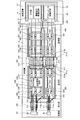
- FIG. 2 is a schematic diagram illustrating a configuration of the endoscope 2 and the processing device 3.
- the endoscope 2 includes a distal end portion 101, an insertion portion 100, an operation portion 200, a universal cord 300, and a proximal end portion 400.
- the distal end portion 101 includes the imaging device 20 (imaging unit) and the actuator 30.
- the imaging device 20 includes an optical system that forms a subject image on a light receiving surface of the imaging device, an imaging device that receives the subject image formed by the optical system, and generates an imaging signal by performing photoelectric conversion.
- the optical system is configured using one or a plurality of lenses and the like, is configured to be movable along the optical axis direction, and moves under the drive of the actuator 30 in the optical axis direction to set the focal length. change.
- the image sensor sequentially generates an image signal based on a drive signal, a control signal, a drive power, and the like transmitted from a first cable 110 provided in an insertion section 100 described later, and generates the generated image signal. Output to the first cable 110.
- the imaging device is configured using, for example, a CMOS (Complementary Metal Oxide Semiconductor) or a CCD (Charge Coupled Device).
- the actuator 30 is configured using a cylindrical magnetic body or the like on which the coil and the optical system of the imaging device 20 are mounted.
- the actuator 30 generates a magnetic field when the drive signal transmitted from the first cable 110 flows through the coil, and the magnetic material moves in the optical axis direction by the magnetic field, so that the focal length of the optical system of the imaging device 20 is changed.
- the actuator 30 may use a voice coil motor, or may be formed using a shape memory alloy, and may change its shape when a voltage is applied.
- the insertion section 100 has the first cable 110.
- the first cable 110 has a first actuator signal line 111 and a first imaging signal line 112.
- the first actuator signal line 111 is configured using a two-core shielded wire, and has an outer diameter of the first ⁇ 1. One end of the first actuator signal line 111 is electrically connected to the actuator 30, and the other end is electrically connected to a relay board 210 of the operation unit 200 described later. Further, the shield line 111 a of the first actuator signal line 111 is electrically connected to the relay board 210.
- the first imaging signal line 112 is configured using a plurality of (the number of signals necessary for driving the imaging device 20 and the video output signal) shield wires, and has an outer diameter of the second ⁇ 2.
- One end of the first imaging signal line 112 is electrically connected to the imaging device 20, and the other end is electrically connected to the relay board 210.
- the shield line 112 a of the first imaging signal line 112 is electrically connected to the relay board 210.
- the operation unit 200 has a relay board 210 to which the first cable 110 is electrically connected.
- the relay board 210 has a first wiring part 220 and a second wiring part 230.
- the first wiring section 220 is electrically connected to the first actuator signal line 111 and the shield line 111a.
- the first wiring section 220 has a plurality of distal connection lands 221, a proximal connection land 222, a plurality of signal lines 223, and a first ground plane 224.
- the other end of the first actuator signal line 111 is electrically connected to the distal end connection land 221 by solder or the like, and the signal line 223 is electrically connected to the first actuator signal line 111 by solder or the like.
- the plurality of signal lines 223 electrically connect the distal connection land 221 and the proximal connection land 222.
- the proximal end connection land 222 is electrically connected to a second actuator signal line 311 of the universal cord 300 described later.
- the first ground plane 224 is electrically connected to the shield line 111a of the first actuator signal line 111, and electrically connected to the shield line 311a of the second actuator signal line 311 of the universal cord 300 described later. Connected.
- the second wiring section 230 is electrically connected to the first imaging signal line 112 and the shield line 112a.
- the second wiring section 230 includes a plurality of distal connection lands 231, a buffer 232, a waveform shaping circuit 233, a plurality of proximal connection lands 234, a signal line 235, a second ground plane 236, And
- the other end of the first imaging signal line 112 is electrically connected to the distal end side connection land 231, and the signal line 235 is connected to the other end side.
- the plurality of signal lines 235 are electrically connected to the base end connection land 234 via the buffer 232 or the waveform shaping circuit 233.
- the buffer 232 has one end electrically connected to the distal connection land 231 via the signal line 235, and the other end electrically connected to the proximal connection land 234 via the signal line 235.
- the buffer 232 temporarily holds the imaging signal generated by the imaging device 20 and outputs the signal to a second imaging signal line 312 of the universal code 300 described later by amplifying the imaging signal.
- the buffer 232 functions as a processing circuit.
- the waveform shaping circuit 233 performs waveform shaping on the drive signal, control signal, drive power, and the like input from the second imaging signal line 312 of the universal code 300 to be described later, to the first imaging signal line 112. Output.
- the second ground plane 236 has one end electrically connected to the shield line 112a and the other end electrically connected to a shield line 312a of a second imaging signal line 312 of the universal cord 300 described later. Connected. In addition, the second ground plane 236 and the first ground plane 224 are provided on the same surface of the relay board 210 in a spatially separated state.
- the universal cord 300 has at least the second cable 310.
- the second cable 310 has a second actuator signal line 311 and a second imaging signal line 312.
- the second actuator signal line 311 is configured using a two-core shielded wire, and has an outer diameter of a second ⁇ 2. Specifically, the second actuator signal line 311 has an outer diameter larger than the outer diameter of the first actuator signal line 111 (first ⁇ 1 ⁇ second ⁇ 2). One end of the second actuator signal line 311 is electrically connected to the base end connection land 222 of the first wiring portion 220, and the other end is connected to a base end 400 described later. Further, one end of the shield line 311 a of the second actuator signal line 311 is electrically connected to the first ground plane 224, and the other end is connected to the base end 400.
- the second imaging signal line 312 is configured using a plurality of (the number of signals required for driving the imaging device 20 and the video output signal) core shield lines.
- the outer diameter has a fourth ⁇ 4.
- the second imaging signal line 312 has an outer diameter larger than the outer diameter of the first imaging signal line 112 (second ⁇ 2 ⁇ fourth ⁇ 4).
- One end of the second imaging signal line 312 is electrically connected to the proximal connection land 234 of the second wiring portion 230, and the other end is electrically connected to the proximal end 400.
- one end of the shield line 312 a of the second imaging signal line 312 is electrically connected to the second ground plane 236, and the other end is connected to the base end 400.
- the base end portion 400 has a connector board 410 to which the second cable 310 is electrically connected and a connector section 420 to be detachably and electrically connected to the processing apparatus 3. Further, the connector board 410 has a third wiring portion 430 and a fourth wiring portion 440.
- the third wiring portion 430 is electrically connected to the second actuator signal line 311 and the shield line 311a.
- the third wiring portion 430 has a plurality of distal connection lands 431, a plurality of proximal connection lands 432, a plurality of signal lines 433, and a third ground plane 434.
- One end of the distal end side connection land 431 is electrically connected to the second actuator signal line 311 and the signal line 433 is electrically connected thereto.
- the plurality of signal lines 433 electrically connect the distal connection land 431 and the proximal connection land 432.
- the proximal connection land 432 is electrically connected to the connector 420 via the signal line 433.
- the third ground plane 434 is electrically connected to the shield line 311 a of the second actuator signal line 311.
- the fourth wiring portion 440 is electrically connected to the second imaging signal line 312 and the shield line 312a.
- the fourth wiring portion 440 has a plurality of distal connection lands 441, a plurality of proximal connection lands 442, a plurality of signal lines 443, and a fourth ground plane 444.
- the distal end side connection land 441 is electrically connected to the second imaging signal line 312, and is also electrically connected to the signal line 443.
- the plurality of signal lines 443 electrically connect the distal connection land 441 and the proximal connection land 442.
- the proximal connection land 442 is electrically connected to the connector 420 via the signal line 443.
- the fourth ground plane 444 has a connection portion 445 that is electrically connected to the third ground plane 434 on the same surface of the connector board 410.
- the fourth ground plane 444 has the wiring 446 electrically connected to the connector 420, and is electrically connected to the common ground plane 34 provided in the processing device 3 described later via the connector 420. Is done.
- the connector 420 has one end electrically connected to the base connection land 432 via the signal line 433 and one end electrically connected to the base connection land 442 via the signal line 443. Further, the connector section 420 is electrically connected to the wiring 446 of the fourth ground plane 444.
- the connector 420 is detachably connected to the processing device 3 and is electrically connected to various circuits of the processing device 3 and a common ground plane 34 described later.
- the processing device 3 includes an analog front end 31 (hereinafter, referred to as “AFE 31”), an image sensor driving circuit 32, an actuator driving circuit 33, and a common ground plane.
- AFE 31 analog front end 31
- image sensor driving circuit 32 an image sensor driving circuit 32
- actuator driving circuit 33 an actuator driving circuit 33
- the AFE 31 performs predetermined signal processing such as A / D conversion processing and noise removal processing on the imaging signal input via the second imaging signal line 312 and the connector unit 420 to perform image processing (not shown). Output to the engine.
- the imaging device driving circuit 32 generates a driving signal, a control signal, and a driving power for driving the imaging device 20, and transmits the driving signal, the control signal, and the driving power to the second imaging device via the connector unit 420. Output to the signal line 312.
- the actuator drive circuit 33 generates a drive signal for driving the actuator 30, and outputs the generated drive signal to the second actuator signal line 311 via the connector 420.
- the common ground plane 34 is electrically connected to the fourth ground plane 444 via the connector 420 and the wiring 446.
- the first ground plane 224 and the second ground plane 236 are provided separately on the relay board 210, and the second actuator signal line 311 is connected to the first actuator. Since the outer diameter of the drive signal line 111 is larger than the outer diameter of the drive signal line 111, the drive circuit can be downsized, and the noise generated from the drive signal for driving the actuator 30 is prevented from being superimposed on the imaging signal. be able to. As a result, observation performance can be improved.
- the relay board 210 is electrically connected from the connector board 410 via the second actuator signal line 311 having a low resistance value, and the actuator 30 is connected from the relay board 210 to the first actuator signal. Since the connection is made electrically by the line 111, the combined impedance of the signal line for the actuator 30 can be reduced, so that the drive voltage of the actuator drive circuit 33 of the processing device 3 can be reduced.
- the endoscope according to the second embodiment has a different configuration from the endoscope 2 according to the first embodiment. Specifically, in the first embodiment, the first ground plane 224 and the second ground plane 236 are spatially separated on the same plane on the relay board 210. In mode 2, the first ground plane and the second ground plane are arranged on different planes.
- the configuration of the endoscope according to the second embodiment will be described. Note that the same components as those of the endoscope system 1 according to Embodiment 1 described above are denoted by the same reference numerals, and detailed description thereof will be omitted.
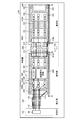
- FIG. 3 is a schematic diagram illustrating a configuration of a front side of the endoscope.
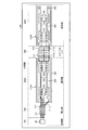
- FIG. 4 is a schematic diagram showing a configuration on the back side of the endoscope.
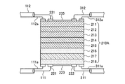
- FIG. 5 is a sectional view taken along the line VV shown in FIG.
- FIG. 6 is a sectional view taken along line VI-VI shown in FIG.
- the endoscope 2A shown in FIGS. 3 to 6 includes an operation unit 200A and a base end 400A instead of the operation unit 200 and the base end 400 of the endoscope 2 according to the first embodiment.
- the operation unit 200A and the base end 400A include a relay board 210A and a connector board 410A instead of the relay board 210 and the connector board 410 according to the first embodiment.
- the relay board 210A and the connector board 410A shown in FIG. 3 to FIG. 6 are formed by an eight-layer board, and the signal cables for imaging (the first imaging signal line 112 and the second imaging signal line 312) are on the front side.
- an imaging signal ground (a second ground plane 236 and a fourth ground plane 444) are provided, and the back side is provided with an actuator signal cable (a first actuator signal line 111 and a second actuator signal line). 311) and an actuator signal ground (first ground plane 224, third ground plane 434).
- the relay substrate 210A includes a first layer 211, a second layer 212, a third layer 213, a fourth layer 214, a fifth layer 215, a sixth layer 216, from the front side to the back side.
- the seventh layer 217 and the eighth layer 218 are formed in this order.
- a second ground plane 236, a buffer 232, and a waveform shaping circuit 233 are provided on the first layer 211.
- the second ground plane 236 is electrically connected to a third layer 213 functioning as a ground layer for the imaging device 20 by a through via (not shown) or a TSV (Through Silicon Via) (not shown).
- a circuit and a capacitor for wiring the buffer 232, the waveform shaping circuit 233, and the like are formed.
- the fourth layer 214 and the fifth layer 215 function as power supply layers for imaging reliability.
- the sixth layer 216 functions as a ground layer for the actuator 30.
- the seventh layer 217 functions as a signal layer of the actuator 30.
- the eighth layer 218 is provided with a distal connection land 221, a proximal connection land 222, and a first ground plane 224.
- the first ground plane 224 is electrically connected to the sixth layer 216 by a not-shown through via, TSV, or the like. Further, the first ground plane 224 and the second ground plane 236 are stacked while being insulated from each other.
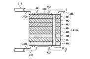
- the connector substrate 410A includes a first layer 411, a second layer 412, a third layer 413, a fourth layer 414, and a fifth layer 411 from the back side to the front side and from the front side to the back side.
- the layer 415, the sixth layer 416, the seventh layer 417, and the eighth layer 418 are formed in this order.
- the first layer 411 is provided with the distal connection land 441, the proximal connection land 442, and the fourth ground plane 444.
- the fourth ground plane 444 is electrically connected to a third layer 413 functioning as a ground layer for the imaging device 20 by a via, a TSV, or the like (not shown).
- a circuit and a capacitor are formed in the second layer 412.
- the fourth layer 414 and the fifth layer 415 function as power layers for imaging reliability.
- the sixth layer 416 functions as a ground layer for the actuator 30.
- the seventh layer 417 functions as a signal layer of the actuator 30.
- the eighth layer 418 is provided with a distal connection land 431, a proximal connection land 432, and a third ground plane 434.
- Third ground plane 434 is electrically connected to fourth ground plane 444 by through via 445.
- the relay board 210A and the connector board 410A have a laminated structure, and the plane area of the relay board 210A and the connector board 410A can be reduced, so that the operation section 200A can be downsized. And the cost of assembling the endoscope 2A can be reduced.
- the second layer 212, 412, the fourth layer 214, 414, and the fifth layer for transmitting the imaging drive signal and the actuator drive signal in the relay board 210A and the connector board 410A.
- Layer 215.415 and the seventh layers 217 and 417 are sandwiched between the upper and lower ground plane layers, so that noise radiation to the outside can be prevented.
- FIG. 7 is a schematic diagram illustrating a configuration of the endoscope according to the third embodiment.
- An endoscope 2C shown in FIG. 7 includes an operation unit 200C, a universal cord 300C, and a base end, instead of the operation unit 200, the universal cord 300, and the base end 400 of the endoscope 2 according to Embodiment 1 described above. 400C.
- the operation unit 200C, the universal cord 300C, and the base end 400C are replaced with the relay board 210C, the second cable 310C, and the connector instead of the relay board 210, the second cable 310, and the connector board 410 according to the first embodiment. It has a substrate 410C.
- the relay board 210C has a first wiring section 220 and a second wiring section 230.
- the first wiring portion 220 has a distal end side connection land 221c, a fine wire coaxial connector 222c, a plurality of signal lines 223c, and a first ground plane 224.
- the other end of the first actuator signal line 111 is electrically connected to the distal end side connection land 221c, and the plurality of signal lines 223c are electrically connected.
- the plurality of signal lines 223c electrically connect the distal end side connection land 221c and the fine-wire coaxial connector 222c.
- the fine-wire coaxial connector 222c is electrically detachably connected to a second actuator signal line 311c of the universal cord 300C described later.
- the second cable 310C has a second actuator signal line 311c and a second imaging signal line 312.
- the second actuator signal line 311c is configured using a four-core shield line, and is configured by arranging the same two-core shield line as the above-described first actuator signal line 111 in parallel. Thereby, the resistance value of the second actuator signal line 311c can be halved compared to the second actuator signal line 311 of the first embodiment.
- One end of the second actuator signal line 311c is electrically detachably connected to the fine-wire coaxial connector 222c, and the other end is electrically detachably connected to the fine-wire coaxial connector 431c of the connector board 410C described later. Connected.
- the connector board 410C has a third wiring portion 430c and a fourth wiring portion 440.
- the third wiring portion 430c is electrically connected to the second actuator signal line 311c and the shield line 311a.
- the third wiring portion 430c has a fine-wire coaxial connector 431c, a plurality of base end connection lands 432, a plurality of signal lines 433, and a third ground plane 434.
- One end of the fine-wire coaxial connector 431c is electrically connected to the second actuator signal line 311c in a detachable manner, and the signal line 433 is electrically connected to the second actuator signal line 311c.
- the second actuator signal line 311c is detachably connected using the fine-wire coaxial connector 222c and the fine-wire coaxial connector 431c, so that the connector components can be shared. Therefore, the cost of assembling the endoscope 2C can be reduced, and the cost of parts and the improvement of correctability can be realized.
- the second actuator signal line 311c is configured using the same two-core shielded wire as the first actuator signal line 111.
- the second imaging signal line 312 may be a cable having the same diameter as the second actuator signal line 311c.
- the imaging cable can be connected by the common fine-wire coaxial connector, so that the assembly cost of the endoscope 2C can be further reduced, and the cost of parts and the repairability can be improved.
- control device and the light source device are separate bodies, but may be formed integrally.
- Embodiments 1 to 3 of the present disclosure the endoscope system has been described.
- the present invention can be applied to a video microscope for imaging a subject.
- the endoscope system provided with a flexible endoscope was used.
- an endoscope system provided with a hard endoscope, and an industrial endoscope are used.
- the present invention can be applied to an endoscope system provided.
- the endoscope system including the endoscope to be inserted into the subject is used.
- the endoscope system including the hard endoscope, the sinus is used.
- the present invention is also applicable to endoscopes and endoscope systems such as electric scalpels and inspection probes.
- the “unit” described above can be read as “means” or “circuit”.
- the control unit can be read as a control unit or a control circuit.
Landscapes
- Health & Medical Sciences (AREA)
- Life Sciences & Earth Sciences (AREA)
- Surgery (AREA)
- Engineering & Computer Science (AREA)
- Physics & Mathematics (AREA)
- Optics & Photonics (AREA)
- General Health & Medical Sciences (AREA)
- Medical Informatics (AREA)
- Nuclear Medicine, Radiotherapy & Molecular Imaging (AREA)
- Biomedical Technology (AREA)
- Pathology (AREA)
- Radiology & Medical Imaging (AREA)
- Veterinary Medicine (AREA)
- Public Health (AREA)
- Molecular Biology (AREA)
- Biophysics (AREA)
- Heart & Thoracic Surgery (AREA)
- Animal Behavior & Ethology (AREA)
- Signal Processing (AREA)
- Multimedia (AREA)
- Human Computer Interaction (AREA)
- Endoscopes (AREA)
- Astronomy & Astrophysics (AREA)
- General Physics & Mathematics (AREA)
- Instruments For Viewing The Inside Of Hollow Bodies (AREA)
- Closed-Circuit Television Systems (AREA)
Abstract
駆動回路の小型化を図るとともに、撮像信号にノイズが重畳することを防止することができる内視鏡を提供する。内視鏡2は、第1のグランド・プレーン224および第2のグランド・プレーン236を備え、第1のグランド・プレーン224および第2のグランド・プレーン236が中継基板210において分離して設けられ、第2のアクチュエーター用信号線311が第1のアクチュエーター用信号線111の外径より大きい外径を有する。
Description
本開示は、被写体を撮像することによって該被写体の画像データを生成する内視鏡に関する。
従来、内視鏡において、被検体に挿入される挿入部の先端部内に撮像素子を設け、電気ケーブルを経由してビデオプロセッサから撮像素子へ電力の供給を行っている(特許文献1参照)。この技術では、挿入部の基端部に接続された操作部内のフレーム部材が挿入部と電気ケーブルのシールドとを電気的に接続することによって、電気ケーブルの細径化を行っている。
ところで、近年の内視鏡では、先端部にフォーカスレンズと、このフォーカスレンズを光軸方向に移動させるアクチュエーターとを配置し、1つの光学系によって焦点距離を変更可能な内視鏡が知られている。このような焦点距離を変更可能な内視鏡では、患者負担の軽減のため、挿入部の細径化を図っている。
しかしながら、焦点距離を変更可能な内視鏡では、挿入部の細径化に伴って電気ケーブルの導体抵抗値が高くなり、大きな駆動電流が必要なアクチュエーターの場合、駆動装置側の駆動電圧を高く設定する必要があり、駆動回路が大きくなるうえ、アクチュエーターを駆動するための駆動信号から発生するノイズが撮像信号に重畳してしまうという問題点があった。
本開示は、上記に鑑みてなされたものであって、駆動回路の小型化を図るとともに、撮像信号にノイズが重畳することを防止することができる内視鏡を提供することを目的とする。
上述した課題を解決し、目的を達成するために、本開示に係る内視鏡は、処理装置に着脱自在な内視鏡であって、被検体に挿入される挿入部と、焦点調整可能であり、かつ、被写体を撮像することによって撮像信号を生成する撮像装置と、外部から入力される駆動信号に基づいて、前記撮像装置の焦点を調整するアクチュエーターと、を有し、前記挿入部の先端側に設けられた先端部と、第1のケーブルを経由して前記撮像装置および前記アクチュエーターの各々と電気的に接続された中継基板を有し、前記挿入部の基端側に設けられた操作部と、第2のケーブルを経由して前記中継基板と電気的に接続されたコネクタ基板と、前記処理装置から前記駆動信号が入力されるとともに、前記撮像信号を前記処理装置に出力するコネクタ部と、を有する基端部と、を備え、前記第1のケーブルは、前記中継基板から前記アクチュエーターへ前記駆動信号を伝送する第1のアクチュエーター用信号線を有し、前記第2のケーブルは、前記コネクタ基板から前記中継基板へ前記駆動信号を伝送する第2のアクチュエーター用信号線を有し、前記中継基板は、前記第1のアクチュエーター用信号線および前記第2のアクチュエーター用信号線の各々のシールド線が電気的に接続される第1のグランド・プレーンが設けられ、前記第1のアクチュエーター用信号線と前記第2のアクチュエーター用信号線とを電気的に接続する第1の配線部と、前記撮像信号の処理を行う処理回路および第2のグランド・プレーンが設けられた第2の配線部と、を有し、前記第1のグランド・プレーンおよび前記第2のグランド・プレーンは、前記中継基板において分離して設けられ、前記第2のアクチュエーター用信号線は、前記第1のアクチュエーター用信号線の外径より大きい外径を有する。
また、本開示に係る内視鏡は、上記開示において、前記第1のケーブルは、前記撮像装置から前記処理回路へ前記撮像信号を伝送する第1の撮像用信号線をさらに有し、前記第2のケーブルは、前記処理回路から前記コネクタ部へ前記撮像信号を伝送する第2の撮像用信号線をさらに有し、前記第2のグランド・プレーンは、前記第1の撮像用信号線および前記第2の撮像用信号線の各々のシールド線が電気的に接続され、前記コネクタ基板は、前記第2のアクチュエーター用信号線のシールド線が接続される第3のグランド・プレーンが設けられ、前記第2のアクチュエーター用信号線と電気的に接続される第3の配線部と、前記第2の撮像用信号線のシールド線が接続される第4のグランド・プレーンが設けられ、前記第2の撮像用信号線と電気的に接続される第4の配線部と、を有し、前記第3のグランド・プレーンおよび前記第4のグランド・プレーンは、電気的に接続される。
また、本開示に係る内視鏡は、上記開示において、前記第1のグランド・プレーンおよび前記第2のグランド・プレーンは、前記中継基板の同一面上において空間的に分離した状態で設けられる。
また、本開示に係る内視鏡は、上記開示において、前記第1の配線部は、前記中継基板の裏面に設けられ、前記第2の配線部は、前記中継基板の表面に設けられる。
また、本開示に係る内視鏡は、上記開示において、前記第3のグランド・プレーンおよび前記第4のグランド・プレーンは、前記コネクタ基板の同一面上において接続される。
また、本開示に係る内視鏡は、上記開示において、前記第3の配線部は、前記コネクタ基板の裏面に設けられ、前記第4の配線部は、前記コネクタ基板の表面に設けられ、前記第3のグランド・プレーンおよび前記第4のグランド・プレーンは、貫通ビアによって電気的に接続される。
本開示によれば、駆動回路の小型化を図るとともに、撮像信号にノイズが重畳することを防止することができるという効果を奏する。
以下、本開示を実施するための形態(以下、「実施の形態」という)として、被検体内に挿入する挿入部における先端側の先端部に撮像装置(撮像ユニット)を有する内視鏡を備えた内視鏡システムについて説明する。また、この実施の形態により、本開示が限定されるものでない。さらに、図面の記載において、同一の部分には同一の符号を付して説明する。さらにまた、図面は、模式的なものであり、各部材の厚みと幅との関係、各部材の比率等は、現実と異なることに留意する必要がある。また、図面の相互間において、互いの寸法や比率が異なる部分が含まれている。
(実施の形態1)
〔内視鏡システムの構成〕
図1は、本開示の実施の形態1に係る内視鏡システムの全体構成を模式的に示す概略図である。図1に示す内視鏡システム1は、内視鏡2と、処理装置3と、表示装置4と、光源装置5と、を備える。
〔内視鏡システムの構成〕
図1は、本開示の実施の形態1に係る内視鏡システムの全体構成を模式的に示す概略図である。図1に示す内視鏡システム1は、内視鏡2と、処理装置3と、表示装置4と、光源装置5と、を備える。
内視鏡2は、複数のケーブルを含む挿入部100を被検体の体腔内に挿入し、被検体の体内を撮像することによって生成した撮像信号を処理装置3へ出力する。内視鏡2は、挿入部100と、操作部200と、ユニバーサルコード300と、基端部400と、を備える。
挿入部100は、内部に複数のケーブルおよびライトガイドを有し、被検体の体腔内に挿入される。挿入部100は、被検体の体腔内に挿入される先端側の先端部101に、被検体の体内を撮像することによって撮像信号を生成する撮像装置20およびアクチュエーター30が設けられ、基端側102側に操作部200が接続される。挿入部100は、処理装置3から供給された電力および駆動信号を撮像装置20およびアクチュエーター30へ伝送するとともに、撮像装置20によって生成された撮像信号を基端側102側へ伝送する。
操作部200は、内部に各種回路が実装された基板を内蔵するとともに、内視鏡2に関する各種操作の入力を受け付ける。また、操作部200は、ユニバーサルコード300が接続される。操作部200は、各種のスイッチ、トグルスイッチおよびボタン等を用いて構成される。
ユニバーサルコード300は、内部に複数のケーブルおよびライトガイドを有し、基端側301側に基端部400が接続される。ユニバーサルコード300は、基端部400および操作部200を経由して処理装置3から供給された電力および駆動信号を挿入部100へ伝送するとともに、挿入部100および操作部200を経由して撮像装置20によって生成された撮像信号を基端側102側へ伝送する。
基端部400は、処理装置3および光源装置5に着脱自在に接続される。基端部400は、処理装置3から供給された電力および駆動信号をユニバーサルコード300へ伝送するとともに、ユニバーサルコード300を経由して入力された撮像信号を処理装置3へ伝送する。
処理装置3は、基端部400へ電力および駆動信号を出力するとともに、基端部400から入力された撮像信号を受信する。処理装置3は、撮像信号に対して所定の画像処理を施して表示装置4へ出力する。処理装置3は、内視鏡システム1の各部を制御する。処理装置3は、例えばCPU(Central Processing Unit)、GPU(Graphics Processing Unit)、FPGA(Field Programmable Gate Array)、DSP(Digital Signal Processing)、各種回路、揮発性メモリおよび不揮発性メモリ等を用いて構成される。
表示装置4は、処理装置3が画像処理を施した撮像信号に対応する画像を表示する。また、表示装置4は、内視鏡システム1に関する各種情報を表示する。表示装置4は、液晶または有機EL(Electro Luminescence)等を用いて構成される。
光源装置5は、基端部400を経由して挿入部100の先端部101側から被検体(被写体)に向けて照射光を照射するための照明光を供給する。光源装置5は、ハロゲンランプまたは白色光を発する白色LED(Light Emitting Diode)等を用いて構成される。なお、実施の形態1では、光源装置5に同時方式の照明方式を用いる場合について説明するが、撮像装置20の種別に応じて適宜変更することができ、例えば面順次方式の照明方式であってもよい。
〔内視鏡および処理装置の構成〕
次に、内視鏡2および処理装置3の詳細な構成について説明する。図2は、内視鏡2および処理装置3の構成を示す模式図である。
次に、内視鏡2および処理装置3の詳細な構成について説明する。図2は、内視鏡2および処理装置3の構成を示す模式図である。
〔内視鏡の構成〕
まず、内視鏡2の構成について説明する。
図2に示すように、内視鏡2は、先端部101と、挿入部100と、操作部200と、ユニバーサルコード300と、基端部400と、を備える。
まず、内視鏡2の構成について説明する。
図2に示すように、内視鏡2は、先端部101と、挿入部100と、操作部200と、ユニバーサルコード300と、基端部400と、を備える。
先端部101は、撮像装置20(撮像ユニット)と、アクチュエーター30と、を有する。
撮像装置20は、被写体像を撮像素子の受光面に結像する光学系と、この光学系によって結像された被写体像を受光し、光電変換を行うことによって撮像信号を生成する撮像素子と、を有する。このうち、光学系は、1または複数のレンズ等を用いて構成され、光軸方向に沿って移動可能に構成され、アクチュエーター30の駆動のもと、光軸方向に移動することによって焦点距離を変更する。また、撮像素子は、後述する挿入部100内に設けられた第1のケーブル110から伝送された駆動信号、制御信号および駆動電力等に基づいて、撮像信号を順次生成し、生成した撮像信号を第1のケーブル110へ出力する。撮像素子は、例えばCMOS(Complementary Metal Oxide Semiconductor)やCCD(Charge Coupled Device)等を用いて構成される。
アクチュエーター30は、コイルおよび撮像装置20の光学系を搭載した筒状をなす磁性体等を用いて構成される。アクチュエーター30は、コイルに第1のケーブル110から伝送された駆動信号が流れることで磁界が発生し、この磁界によって磁性体が光軸方向に移動することで、撮像装置20の光学系の焦点距離を変化させる。なお、アクチュエーター30は、ボイスコイルモータを用いてものであってもよいし、形状記憶合金を用いて構成し、電圧が印加されることによって形状を変化させるものであってもよい。
挿入部100は、第1のケーブル110を有する。第1のケーブル110は、第1のアクチュエーター用信号線111と、第1の撮像用信号線112と、を有する。
第1のアクチュエーター用信号線111は、2心シールド線を用いて構成され、外径が第1のφ1である。第1のアクチュエーター用信号線111は、一端側がアクチュエーター30に電気的に接続され、他端側が後述する操作部200の中継基板210に電気的に接続される。また、第1のアクチュエーター用信号線111のシールド線111aが中継基板210に電気的に接続される。
第1の撮像用信号線112は、複数(撮像装置20を駆動する信号と映像出力信号に必要な本数)のシールド線を用いて構成され、外径が第2のφ2を有する。第1の撮像用信号線112は、一端側が撮像装置20に電気的に接続され、他端側が中継基板210に電気的に接続される。また、第1の撮像用信号線112のシールド線112aが中継基板210に電気的に接続される。
操作部200は、第1のケーブル110が電気的に接続される中継基板210を有する。中継基板210は、第1の配線部220と、第2の配線部230と、を有する。
第1の配線部220は、第1のアクチュエーター用信号線111およびシールド線111aが電気的に接続される。第1の配線部220は、複数の先端側接続ランド221と、基端側接続ランド222と、複数の信号線223と、第1のグランド・プレーン224と、を有する。
先端側接続ランド221は、第1のアクチュエーター用信号線111の他端側が半田等によって電気的に接続され、かつ信号線223が半田等によって電気的に接続される。複数の信号線223は、先端側接続ランド221と基端側接続ランド222とを電気的に接続する。基端側接続ランド222は、後述するユニバーサルコード300の第2のアクチュエーター用信号線311が電気的に接続される。
第1のグランド・プレーン224は、第1のアクチュエーター用信号線111のシールド線111aが電気的に接続され、かつ、後述するユニバーサルコード300の第2のアクチュエーター用信号線311のシールド線311aが電気的に接続される。
第2の配線部230は、第1の撮像用信号線112およびシールド線112aが電気的に接続される。第2の配線部230は、複数の先端側接続ランド231と、バッファ232と、波形整形回路233と、複数の基端側接続ランド234と、信号線235と、第2のグランド・プレーン236と、を有する。
先端側接続ランド231は、第1の撮像用信号線112の他端側が電気的に接続され、かつ信号線235が接続される。複数の信号線235は、バッファ232または波形整形回路233を経由して基端側接続ランド234に電気的に接続される。
バッファ232は、一端側が信号線235を経由して先端側接続ランド231に電気的に接続され、他端側が信号線235を経由して基端側接続ランド234に電気的に接続される。バッファ232は、撮像装置20によって生成された撮像信号を一時的に保持し、かつ、撮像信号の増幅を行うことによって後述するユニバーサルコード300の第2の撮像用信号線312へ出力する。なお、実施の形態1では、バッファ232が処理回路として機能する。
波形整形回路233は、一端側が信号線235を経由して先端側接続ランド231に電気的に接続され、他端側が信号線235を経由して基端側接続ランド234に電気的に接続される。波形整形回路233は、後述するユニバーサルコード300の第2の撮像用信号線312から入力された駆動信号、制御信号および駆動電量等に対して波形整形を行って第1の撮像用信号線112へ出力する。
第2のグランド・プレーン236は、一端側にシールド線112aが電気的に接続され、かつ、他端側に後述するユニバーサルコード300の第2の撮像用信号線312のシールド線312aが電気的に接続される。また、第2のグランド・プレーン236および第1のグランド・プレーン224は、中継基板210の同一面上において空間的に分離した状態で設けられている。
ユニバーサルコード300は、少なくとも第2のケーブル310を有する。第2のケーブル310は、第2のアクチュエーター用信号線311と、第2の撮像用信号線312と、を有する。
第2のアクチュエーター用信号線311は、2心シールド線を用いて構成され、外径が第2のφ2を有する。具体的には、第2のアクチュエーター用信号線311は、外径が第1のアクチュエーター用信号線111の外径より太い外径を有する(第1のφ1<第2のφ2)。第2のアクチュエーター用信号線311は、一端側が第1の配線部220の基端側接続ランド222に電気的に接続され、他端側が後述する基端部400に接続される。さらに、第2のアクチュエーター用信号線311のシールド線311aは、一端側が第1のグランド・プレーン224に電気的に接続され、かつ、他端側が基端部400に接続される。
第2の撮像用信号線312は、複数(撮像装置20を駆動する信号と映像出力信号に必要な本数)の心シールド線を用いて構成される。外径が第4のφ4を有する。第2の撮像用信号線312は、外径が第1の撮像用信号線112の外径より太い外径を有する(第2のφ2<第4のφ4)。第2の撮像用信号線312は、一端側が第2の配線部230の基端側接続ランド234に電気的に接続され、かつ、他端側が基端部400に電気的に接続される。さらに、第2の撮像用信号線312のシールド線312aは、一端側が第2のグランド・プレーン236に電気的に接続され、他端側が基端部400に接続される。
基端部400は、第2のケーブル310が電気的に接続されるコネクタ基板410と、処理装置3に着脱自在に電気的に接続されるコネクタ部420と、を有する。また、コネクタ基板410は、第3の配線部430と、第4の配線部440と、を有する。
第3の配線部430は、第2のアクチュエーター用信号線311およびシールド線311aが電気的に接続される。第3の配線部430は、複数の先端側接続ランド431と、複数の基端側接続ランド432と、複数の信号線433と、第3のグランド・プレーン434と、を有する。先端側接続ランド431は、一端側が第2のアクチュエーター用信号線311が電気的に接続され、かつ、信号線433が電気的に接続される。複数の信号線433は、先端側接続ランド431と基端側接続ランド432とを電気的に接続する。基端側接続ランド432は、信号線433を経由してコネクタ部420に電気的に接続される。また、第3のグランド・プレーン434は、第2のアクチュエーター用信号線311のシールド線311aが電気的に接続される。
第4の配線部440は、第2の撮像用信号線312およびシールド線312aが電気的に接続される。第4の配線部440は、複数の先端側接続ランド441と、複数の基端側接続ランド442と、複数の信号線443と、第4のグランド・プレーン444と、を有する。先端側接続ランド441は、第2の撮像用信号線312が電気的に接続され、かつ信号線443が電気的に接続される。複数の信号線443は、先端側接続ランド441と基端側接続ランド442とを電気的に接続する。基端側接続ランド442は、信号線443を経由してコネクタ部420に電気的に接続される。第4のグランド・プレーン444は、コネクタ基板410の同一面上において第3のグランド・プレーン434と電気的に接続される接続部445を有する。また、第4のグランド・プレーン444は、配線446がコネクタ部420に電気的に接続され、コネクタ部420を経由して後述する処理装置3に設けられた共通グランド・プレーン34に電気的に接続される。
コネクタ部420は、一端側が信号線433を経由して基端側接続ランド432に電気的に接続されるとともに、信号線443を経由して基端側接続ランド442に電気的に接続される。さらに、コネクタ部420は、第4のグランド・プレーン444の配線446と電気的に接続される。コネクタ部420は、処理装置3に着脱自在に接続され、後述する処理装置3の各種回路および共通グランド・プレーン34に電気的に接続される。
〔処理装置の構成〕
次に、処理装置3の構成について説明する。
処理装置3は、アナログ・フロント・エンド31(以下、「AFE31」という)と、撮像素子駆動回路32と、アクチュエーター駆動回路33と、共通グランド・プレーン34と、備える。
次に、処理装置3の構成について説明する。
処理装置3は、アナログ・フロント・エンド31(以下、「AFE31」という)と、撮像素子駆動回路32と、アクチュエーター駆動回路33と、共通グランド・プレーン34と、備える。
AFE31は、第2の撮像用信号線312およびコネクタ部420を経由して入力された撮像信号に対して、A/D変換処理およびノイズ除去処理等の所定の信号処理を行って図示しない画像処理エンジンへ出力する。
撮像素子駆動回路32は、撮像装置20を駆動するための駆動信号、制御信号および駆動電量を生成し、この駆動信号、制御信号および駆動電力を、コネクタ部420を経由して第2の撮像用信号線312へ出力する。
アクチュエーター駆動回路33は、アクチュエーター30を駆動するための駆動信号を生成し、この生成した駆動信号を、コネクタ部420を経由して第2のアクチュエーター用信号線311へ出力する。
共通グランド・プレーン34は、コネクタ部420および配線446を経由して第4のグランド・プレーン444に電気的に接続される。
以上説明した実施の形態1によれば、第1のグランド・プレーン224および第2のグランド・プレーン236が中継基板210において分離して設けられ、第2のアクチュエーター用信号線311が第1のアクチュエーター用信号線111の外径より大きい外径を有するので、駆動回路の小型化を図ることができるとともに、アクチュエーター30を駆動するための駆動信号から発生するノイズが撮像信号に重畳することを防止することができる。この結果、観察性能を向上させることができる。
また、実施の形態1によれば、コネクタ基板410から中継基板210を低抵抗値の第2のアクチュエーター用信号線311で電気的に接続し、中継基板210からアクチュエーター30を第1のアクチュエーター用信号線111で電気的に接続したので、アクチュエーター30用の信号線の合成インピーダンスを低くすることができるため、処理装置3のアクチュエーター駆動回路33による駆動電圧の低電圧化を行うことができる。
(実施の形態2)
次に、実施の形態2について説明する。実施の形態2に係る内視鏡は、上述した実施の形態1に係る内視鏡2と構成が異なる。具体的には、実施の形態1では、中継基板210上における同一面上で空間的に第1のグランド・プレーン224および第2のグランド・プレーン236に分離して配置していたが、実施の形態2では、第1のグランド・プレーンおよび第2のグランド・プレーンを異なる面に配置する。以下においては、実施の形態2に係る内視鏡の構成について説明する。なお、上述した実施の形態1に係る内視鏡システム1と同一の構成には同一の符号を付して詳細な説明は省略する。
次に、実施の形態2について説明する。実施の形態2に係る内視鏡は、上述した実施の形態1に係る内視鏡2と構成が異なる。具体的には、実施の形態1では、中継基板210上における同一面上で空間的に第1のグランド・プレーン224および第2のグランド・プレーン236に分離して配置していたが、実施の形態2では、第1のグランド・プレーンおよび第2のグランド・プレーンを異なる面に配置する。以下においては、実施の形態2に係る内視鏡の構成について説明する。なお、上述した実施の形態1に係る内視鏡システム1と同一の構成には同一の符号を付して詳細な説明は省略する。
〔内視鏡の構成〕
図3は、内視鏡における表面側の構成を示す模式図である。図4は、内視鏡における裏面側の構成を示す模式図である。図5は、図3に示すV-V線断面図である。図6は、図3に示すVI-VI線断面図である。
図3は、内視鏡における表面側の構成を示す模式図である。図4は、内視鏡における裏面側の構成を示す模式図である。図5は、図3に示すV-V線断面図である。図6は、図3に示すVI-VI線断面図である。
図3~図6に示す内視鏡2Aは、上述した実施の形態1に係る内視鏡2の操作部200および基端部400に換えて、操作部200Aおよび基端部400Aを備える。操作部200Aおよび基端部400Aは、上述した実施の形態1に係る中継基板210およびコネクタ基板410に換えて、中継基板210Aおよびコネクタ基板410Aを備える。図3~図6に示す中継基板210Aおよびコネクタ基板410Aは、8層基板によって構成し、表面側を撮像用の信号ケーブル(第1の撮像用信号線112,第2の撮像用信号線312)および撮像信号用グランド(第2のグランド・プレーン236,第4のグランド・プレーン444)を設け、裏面側をアクチュエーター用の信号ケーブル(第1のアクチュエーター用信号線111,第2のアクチュエーター用信号線311)およびアクチュエーター信号用グランド(第1のグランド・プレーン224,第3のグランド・プレーン434)を設けている。
中継基板210Aは、表面側から裏面側に向けて、第1の層211、第2の層212、第3の層213、第4の層214、第5の層215、第6の層216、第7の層217および第8の層218の順に形成される。
第1の層211には、第2のグランド・プレーン236、バッファ232および波形整形回路233が設けられる。第2のグランド・プレーン236は、図示しない貫通ビアやTSV(Through Silicon Via)等によって撮像装置20用のグランド層として機能する第3の層213と電気的に接続される。第2の層212は、例えばバッファ232および波形整形回路233等を配線するための回路や容量が形成される。第4の層214および第5の層215は、撮像信用の電源層として機能する。
第6の層216は、アクチュエーター30用のグランド層として機能する。第7の層217は、アクチュエーター30の信号層として機能する。第8の層218は、先端側接続ランド221、基端側接続ランド222および第1のグランド・プレーン224が設けられる。第1のグランド・プレーン224は、図示しない貫通ビアやTSV等によって第6の層216に電気的に接続される。また、第1のグランド・プレーン224と第2のグランド・プレーン236は、互いに層間で絶縁されている状態で積層される。
コネクタ基板410Aは、裏面側から表面側に向けて、表面側から裏面側に向けて、第1の層411、第2の層412、第3の層413、第4の層414、第5の層415、第6の層416、第7の層417および第8の層418の順に形成される。
第1の層411には、先端側接続ランド441、基端側接続ランド442および第4のグランド・プレーン444が設けられる。第4のグランド・プレーン444は、図示しないビアやTSV等によって撮像装置20用のグランド層として機能する第3の層413と電気的に接続される。第2の層412は、回路や容量が形成される。第4の層414および第5の層415は、撮像信用の電源層として機能する。
第6の層416は、アクチュエーター30用のグランド層として機能する。第7の層417は、アクチュエーター30の信号層として機能する。第8の層418は、先端側接続ランド431、基端側接続ランド432および第3のグランド・プレーン434が設けられる。第3のグランド・プレーン434は、貫通ビア445によって第4のグランド・プレーン444と電気的に接続される。
以上説明した実施の形態2によれば、中継基板210Aおよびコネクタ基板410Aを積層構造とし、中継基板210Aおよびコネクタ基板410Aの平面の面積を小さくすることができるので、操作部200Aの小型化を図ることができるとともに、内視鏡2Aの組み立てコストを低減することができる。
また、実施の形態2によれば、中継基板210Aおよびコネクタ基板410Aにおいて撮像用の駆動信号およびアクチュエーター用の駆動信号を伝送する第2の層212,412、第4の層214,414、第5の層215.415および第7の層217,417を上下のグランド・プレーン層で挟み込んで形成したので、外部へのノイズ放射を防止することができる。
(実施の形態3)
次に、実施の形態3について説明する。上述した実施の形態1では、接続ランドに信号線を半田等によって電気的に接続するとともに、挿入部の第1のケーブルとユニバーサルコードの第2のアクチュエーター用信号線の外径を異ならせていたが、実施の形態3では、同軸コネクタによって電気的に接続するとともに、第1のアクチュエーター用信号線と第2のアクチュエーター用信号線の外径を同じとする。以下においては、実施の形態3に係る内視鏡の構成について説明する。なお、上述した実施の形態1に係る内視鏡システム1と同一の構成には同一の符号を付して詳細な説明は省略する。
次に、実施の形態3について説明する。上述した実施の形態1では、接続ランドに信号線を半田等によって電気的に接続するとともに、挿入部の第1のケーブルとユニバーサルコードの第2のアクチュエーター用信号線の外径を異ならせていたが、実施の形態3では、同軸コネクタによって電気的に接続するとともに、第1のアクチュエーター用信号線と第2のアクチュエーター用信号線の外径を同じとする。以下においては、実施の形態3に係る内視鏡の構成について説明する。なお、上述した実施の形態1に係る内視鏡システム1と同一の構成には同一の符号を付して詳細な説明は省略する。
〔内視鏡の構成〕
図7は、実施の形態3に係る内視鏡の構成を示す模式図である。図7に示す内視鏡2Cは、上述した実施の形態1に係る内視鏡2の操作部200、ユニバーサルコード300および基端部400に換えて、操作部200C、ユニバーサルコード300Cおよび基端部400Cを備える。操作部200C、ユニバーサルコード300Cおよび基端部400Cは、上述した実施の形態1に係る中継基板210、第2のケーブル310およびコネクタ基板410に換えて、中継基板210C、第2のケーブル310Cおよびコネクタ基板410Cを有する。
図7は、実施の形態3に係る内視鏡の構成を示す模式図である。図7に示す内視鏡2Cは、上述した実施の形態1に係る内視鏡2の操作部200、ユニバーサルコード300および基端部400に換えて、操作部200C、ユニバーサルコード300Cおよび基端部400Cを備える。操作部200C、ユニバーサルコード300Cおよび基端部400Cは、上述した実施の形態1に係る中継基板210、第2のケーブル310およびコネクタ基板410に換えて、中継基板210C、第2のケーブル310Cおよびコネクタ基板410Cを有する。
中継基板210Cは、第1の配線部220と、第2の配線部230と、有する。第1の配線部220は、先端側接続ランド221cと、細線同軸用コネクタ222cと、複数の信号線223cと、第1のグランド・プレーン224と、を有する。
先端側接続ランド221cは、第1のアクチュエーター用信号線111の他端側が電気的に接続され、かつ複数の信号線223cが電気的に接続される。複数の信号線223cは、先端側接続ランド221cと細線同軸用コネクタ222cとを電気的に接続する。細線同軸用コネクタ222cは、後述するユニバーサルコード300Cの第2のアクチュエーター用信号線311cが電気的に着脱自在に接続される。
第2のケーブル310Cは、第2のアクチュエーター用信号線311cと、第2の撮像用信号線312と、を有する。第2のアクチュエーター用信号線311cは、4心シールド線を用いて構成され、上述した第1のアクチュエーター用信号線111と同じ2心シールド線を並列に配置して構成される。これにより、第2のアクチュエーター用信号線311cは、上述した実施の形態1の第2のアクチュエーター用信号線311と比して抵抗値を半減することができる。また、第2のアクチュエーター用信号線311cは、一端側が細線同軸用コネクタ222cに電気的に着脱自在に接続され、他端側が後述するコネクタ基板410Cの細線同軸用コネクタ431cに電気的に着脱自在に接続される。
コネクタ基板410Cは、第3の配線部430cと、第4の配線部440と、を有する。第3の配線部430cは、第2のアクチュエーター用信号線311cおよびシールド線311aが電気的に接続される。第3の配線部430cは、細線同軸用コネクタ431cと、複数の基端側接続ランド432と、複数の信号線433と、第3のグランド・プレーン434と、を有する。細線同軸用コネクタ431cは、一端側が第2のアクチュエーター用信号線311cが電気的に着脱自在に接続され、かつ、信号線433が電気的に接続される。
以上説明した実施の形態3によれば、細線同軸用コネクタ222c,細線同軸用コネクタ431cを用いて第2のアクチュエーター用信号線311cを着脱自在に接続することによって、コネクタ部品の共通化を行うことができるので、内視鏡2Cの組み立て時のコストを低減することができるとともに、部品コストの低減や修正性向上を実現することができる。
なお、実施の形態3では、第2のアクチュエーター用信号線311cを第1のアクチュエーター用信号線111と同じ2心シールド線を用いて構成していたが、これに限定されることなく、例えば第2の撮像用信号線312を第2のアクチュエーター用信号線311cと同径のケーブルを用いてもよい。これにより、撮像用ケーブルも共通の細線同軸用コネクタで接続することができるので、さらなる内視鏡2Cの組み立てコストを低減することができるとともに、部品コストの低減および修理性を向上することができる。
(その他の実施の形態)
上述した本開示の実施の形態1~3に開示されている複数の構成要素を適宜組み合わせることによって、種々の発明を形成することができる。例えば、上述した本開示の実施の形態1~3に記載した全構成要素からいくつかの構成要素を削除してもよい。さらに、上述した本開示の実施の形態1~3で説明した構成要素を適宜組み合わせてもよい。
上述した本開示の実施の形態1~3に開示されている複数の構成要素を適宜組み合わせることによって、種々の発明を形成することができる。例えば、上述した本開示の実施の形態1~3に記載した全構成要素からいくつかの構成要素を削除してもよい。さらに、上述した本開示の実施の形態1~3で説明した構成要素を適宜組み合わせてもよい。
また、本開示の実施の形態1~3では、制御装置と光源装置とが別体であったが、一体的に形成してもよい。
また、本開示の実施の形態1~3では、内視鏡システムであったが、被検体を撮像するビデオマイクロスコープであっても適用することができる。
また、本開示の実施の形態1~3では、軟性の内視鏡を備えた内視鏡システムであったが、硬性の内視鏡を備えた内視鏡システム、工業用の内視鏡を備えた内視鏡システムであっても適用することができる。
また、本開示の実施の形態1~3では、被検体に挿入される内視鏡を備えた内視鏡システムであったが、例えば硬性の内視鏡を備えた内視鏡システム、副鼻腔内視鏡および電気メスや検査プローブ等の内視鏡システムであっても適用することができる。
また、本開示の実施の形態1~3では、上述してきた「部」は、「手段」や「回路」などに読み替えることができる。例えば、制御部は、制御手段や制御回路に読み替えることができる。
以上、本願の実施の形態のいくつかを図面に基づいて詳細に説明したが、これらは例示であり、本開示の欄に記載の態様を始めとして、当業者の知識に基づいて種々の変形、改良を施した他の形態で本開示を実施することが可能である。
1 内視鏡システム
2,2A,2C 内視鏡
3 処理装置
4 表示装置
5 光源装置
20 撮像装置
30 アクチュエーター
31 AFE
32 撮像素子駆動回路
33 アクチュエーター駆動回路
34 共通グランド・プレーン
100 挿入部
101 先端部
102 基端側
110 第1のケーブル
111 第1のアクチュエーター用信号線
111a,112a,311a,312a シールド線
112 第1の撮像用信号線
200,200A,200C 操作部
210,210A,210C 中継基板
220 第1の配線部
224 第1のグランド・プレーン
230 第2の配線部
232 バッファ
233 波形整形回路
236 第2のグランド・プレーン
300,300C ユニバーサルコード
310,310C 第2のケーブル
311,311c 第2のアクチュエーター用信号線
312 第2の撮像用信号線
400,400A,400C 基端部
410,410A,410C コネクタ基板
420 コネクタ部
430,430c 第3の配線部
434 第3のグランド・プレーン
440 第4の配線部
444 第4のグランド・プレーン
445 貫通ビア
Claims (6)
- 処理装置に着脱自在な内視鏡であって、
被検体に挿入される挿入部と、
焦点調整可能であり、かつ、被写体を撮像することによって撮像信号を生成する撮像装置と、外部から入力される駆動信号に基づいて、前記撮像装置の焦点を調整するアクチュエーターと、を有し、前記挿入部の先端側に設けられた先端部と、
第1のケーブルを経由して前記撮像装置および前記アクチュエーターの各々と電気的に接続された中継基板を有し、前記挿入部の基端側に設けられた操作部と、
第2のケーブルを経由して前記中継基板と電気的に接続されたコネクタ基板と、前記処理装置から前記駆動信号が入力されるとともに、前記撮像信号を前記処理装置に出力するコネクタ部と、を有する基端部と、
を備え、
前記第1のケーブルは、前記中継基板から前記アクチュエーターへ前記駆動信号を伝送する第1のアクチュエーター用信号線を有し、
前記第2のケーブルは、前記コネクタ基板から前記中継基板へ前記駆動信号を伝送する第2のアクチュエーター用信号線を有し、
前記中継基板は、
前記第1のアクチュエーター用信号線および前記第2のアクチュエーター用信号線の各々のシールド線が電気的に接続される第1のグランド・プレーンが設けられ、前記第1のアクチュエーター用信号線と前記第2のアクチュエーター用信号線とを電気的に接続する第1の配線部と、
前記撮像信号の処理を行う処理回路および第2のグランド・プレーンが設けられた第2の配線部と、
を有し、
前記第1のグランド・プレーンおよび前記第2のグランド・プレーンは、前記中継基板において分離して設けられ、
前記第2のアクチュエーター用信号線は、前記第1のアクチュエーター用信号線の外径より大きい外径を有する
内視鏡。 - 前記第1のケーブルは、前記撮像装置から前記処理回路へ前記撮像信号を伝送する第1の撮像用信号線をさらに有し、
前記第2のケーブルは、前記処理回路から前記コネクタ部へ前記撮像信号を伝送する第2の撮像用信号線をさらに有し、
前記第2のグランド・プレーンは、前記第1の撮像用信号線および前記第2の撮像用信号線の各々のシールド線が電気的に接続され、
前記コネクタ基板は、
前記第2のアクチュエーター用信号線のシールド線が接続される第3のグランド・プレーンが設けられ、前記第2のアクチュエーター用信号線と電気的に接続される第3の配線部と、
前記第2の撮像用信号線のシールド線が接続される第4のグランド・プレーンが設けられ、前記第2の撮像用信号線と電気的に接続される第4の配線部と、
を有し、
前記第3のグランド・プレーンおよび前記第4のグランド・プレーンは、電気的に接続される
請求項1に記載の内視鏡。 - 前記第1のグランド・プレーンおよび前記第2のグランド・プレーンは、前記中継基板の同一面上において空間的に分離した状態で設けられる
請求項1または2に記載の内視鏡。 - 前記第1の配線部は、前記中継基板の裏面に設けられ、
前記第2の配線部は、前記中継基板の表面に設けられる
請求項1または2に記載の内視鏡。 - 前記第3のグランド・プレーンおよび前記第4のグランド・プレーンは、前記コネクタ基板の同一面上において接続される
請求項2に記載の内視鏡。 - 前記第3の配線部は、前記コネクタ基板の裏面に設けられ、
前記第4の配線部は、前記コネクタ基板の表面に設けられ、
前記第3のグランド・プレーンおよび前記第4のグランド・プレーンは、貫通ビアによって電気的に接続される
請求項2に記載の内視鏡。
Priority Applications (2)
| Application Number | Priority Date | Filing Date | Title |
|---|---|---|---|
| JP2020527200A JP6993508B2 (ja) | 2018-06-26 | 2019-03-01 | 内視鏡 |
| US17/119,280 US11284779B2 (en) | 2018-06-26 | 2020-12-11 | Endoscope |
Applications Claiming Priority (2)
| Application Number | Priority Date | Filing Date | Title |
|---|---|---|---|
| JP2018-120972 | 2018-06-26 | ||
| JP2018120972 | 2018-06-26 |
Related Child Applications (1)
| Application Number | Title | Priority Date | Filing Date |
|---|---|---|---|
| US17/119,280 Continuation US11284779B2 (en) | 2018-06-26 | 2020-12-11 | Endoscope |
Publications (1)
| Publication Number | Publication Date |
|---|---|
| WO2020003615A1 true WO2020003615A1 (ja) | 2020-01-02 |
Family
ID=68986867
Family Applications (1)
| Application Number | Title | Priority Date | Filing Date |
|---|---|---|---|
| PCT/JP2019/008053 WO2020003615A1 (ja) | 2018-06-26 | 2019-03-01 | 内視鏡 |
Country Status (3)
| Country | Link |
|---|---|
| US (1) | US11284779B2 (ja) |
| JP (1) | JP6993508B2 (ja) |
| WO (1) | WO2020003615A1 (ja) |
Citations (2)
| Publication number | Priority date | Publication date | Assignee | Title |
|---|---|---|---|---|
| JPH1147091A (ja) * | 1997-08-06 | 1999-02-23 | Asahi Optical Co Ltd | 電子内視鏡 |
| JP2011036585A (ja) * | 2009-08-18 | 2011-02-24 | Hoya Corp | 電子内視鏡および電子内視鏡システム |
Family Cites Families (19)
| Publication number | Priority date | Publication date | Assignee | Title |
|---|---|---|---|---|
| JPS5846308A (ja) * | 1981-09-12 | 1983-03-17 | Fuji Photo Film Co Ltd | 固体撮像素子を移動する内視鏡用ズ−ムレンズ |
| US6104426A (en) * | 1996-03-23 | 2000-08-15 | Street; Graham S. B. | Stereo-endoscope |
| DE69732115D1 (de) * | 1996-04-03 | 2005-02-03 | Graham Stewart B Street | Vorrichtung und verfahren für die stereoskopische endoskopie |
| JPH10133126A (ja) * | 1996-09-03 | 1998-05-22 | Olympus Optical Co Ltd | 内視鏡撮像装置 |
| JP3360799B2 (ja) * | 1997-08-07 | 2002-12-24 | ペンタックス株式会社 | 内視鏡の対物駆動機構 |
| JP4002680B2 (ja) * | 1998-07-15 | 2007-11-07 | オリンパス株式会社 | 測距装置付きカメラ |
| US7037258B2 (en) * | 1999-09-24 | 2006-05-02 | Karl Storz Imaging, Inc. | Image orientation for endoscopic video displays |
| US6970189B1 (en) * | 2000-05-31 | 2005-11-29 | Ipac Acquisition Subsidiary I, Llc | Method and system for automatically configuring a hand-held camera using wireless communication to improve image quality |
| WO2002062262A2 (en) * | 2001-02-02 | 2002-08-15 | Insight Instruments, Inc. | Endoscope system and method of use |
| JP2003010111A (ja) * | 2001-06-27 | 2003-01-14 | Olympus Optical Co Ltd | 撮像装置 |
| US20050143664A1 (en) * | 2003-10-09 | 2005-06-30 | Zhongping Chen | Scanning probe using MEMS micromotor for endosocopic imaging |
| JP4754871B2 (ja) * | 2005-05-11 | 2011-08-24 | オリンパスメディカルシステムズ株式会社 | 内視鏡の先端部 |
| JP4827477B2 (ja) * | 2005-09-22 | 2011-11-30 | オリンパスメディカルシステムズ株式会社 | 内視鏡システムおよび当該内視鏡システムに適用するアダプタ |
| US8427533B2 (en) * | 2007-12-19 | 2013-04-23 | Olympus Medical Systems Corp. | Image pickup apparatus, electronic endoscope, and lens unit |
| JP5100457B2 (ja) * | 2008-03-10 | 2012-12-19 | オリンパスメディカルシステムズ株式会社 | 内視鏡観察システム |
| JP5308716B2 (ja) | 2008-05-21 | 2013-10-09 | オリンパスメディカルシステムズ株式会社 | 電子内視鏡装置 |
| KR101544742B1 (ko) * | 2008-12-08 | 2015-08-17 | 삼성전자주식회사 | 촬상 장치 및 촬상 방법 |
| WO2013042647A1 (ja) * | 2011-09-22 | 2013-03-28 | オリンパスメディカルシステムズ株式会社 | 内視鏡 |
| EP3241485A1 (en) * | 2016-03-03 | 2017-11-08 | Olympus Corporation | Endoscope system, and method for operating endoscope system |
-
2019
- 2019-03-01 JP JP2020527200A patent/JP6993508B2/ja active Active
- 2019-03-01 WO PCT/JP2019/008053 patent/WO2020003615A1/ja active Application Filing
-
2020
- 2020-12-11 US US17/119,280 patent/US11284779B2/en active Active
Patent Citations (2)
| Publication number | Priority date | Publication date | Assignee | Title |
|---|---|---|---|---|
| JPH1147091A (ja) * | 1997-08-06 | 1999-02-23 | Asahi Optical Co Ltd | 電子内視鏡 |
| JP2011036585A (ja) * | 2009-08-18 | 2011-02-24 | Hoya Corp | 電子内視鏡および電子内視鏡システム |
Also Published As
| Publication number | Publication date |
|---|---|
| US20210093167A1 (en) | 2021-04-01 |
| JP6993508B2 (ja) | 2022-01-13 |
| US11284779B2 (en) | 2022-03-29 |
| JPWO2020003615A1 (ja) | 2021-04-22 |
Similar Documents
| Publication | Publication Date | Title |
|---|---|---|
| EP2351517B1 (en) | Signal output board and endoscope | |
| EP3050491B1 (en) | Endoscope device | |
| EP1911389A1 (en) | Light emitting unit | |
| JP5964003B1 (ja) | 撮像ユニット、撮像モジュールおよび内視鏡システム | |
| WO2015045630A1 (ja) | 撮像モジュールおよび内視鏡装置 | |
| WO2014171482A1 (ja) | 撮像装置および電子内視鏡 | |
| US20160206186A1 (en) | Imaging module and endoscope apparatus | |
| WO2017130371A1 (ja) | 撮像装置および内視鏡 | |
| WO2020003615A1 (ja) | 内視鏡 | |
| WO2015194460A1 (ja) | ケーブル接続構造および内視鏡装置 | |
| JP6307227B2 (ja) | 撮像ユニットおよび内視鏡装置 | |
| JP2018166986A (ja) | 内視鏡及び内視鏡装置 | |
| CN111918597A (zh) | 内窥镜 | |
| JP6081347B2 (ja) | 撮像ユニットおよび内視鏡 | |
| JP3278393B2 (ja) | 内視鏡装置 | |
| JP2001311879A (ja) | 内視鏡およびその製造方法 | |
| US11395406B2 (en) | Camera head | |
| JPH01198182A (ja) | 撮像装置 | |
| JP6736377B2 (ja) | 電子内視鏡装置 | |
| JP2002045333A (ja) | 内視鏡撮像装置 | |
| JPWO2016185554A1 (ja) | 撮像ユニットおよび内視鏡 | |
| WO2017115441A1 (ja) | 実装構造体、撮像装置および内視鏡 | |
| JP2022179301A (ja) | 内視鏡撮像装置及び内視鏡 | |
| JP2021037161A (ja) | 照明モジュール及び内視鏡 | |
| JP6223092B2 (ja) | 内視鏡装置 |
Legal Events
| Date | Code | Title | Description |
|---|---|---|---|
| 121 | Ep: the epo has been informed by wipo that ep was designated in this application |
Ref document number: 19825254 Country of ref document: EP Kind code of ref document: A1 |
|
| ENP | Entry into the national phase |
Ref document number: 2020527200 Country of ref document: JP Kind code of ref document: A |
|
| NENP | Non-entry into the national phase |
Ref country code: DE |
|
| 122 | Ep: pct application non-entry in european phase |
Ref document number: 19825254 Country of ref document: EP Kind code of ref document: A1 |