WO2020003341A1 - ロータ、電動機、送風機および空気調和装置 - Google Patents
ロータ、電動機、送風機および空気調和装置 Download PDFInfo
- Publication number
- WO2020003341A1 WO2020003341A1 PCT/JP2018/023964 JP2018023964W WO2020003341A1 WO 2020003341 A1 WO2020003341 A1 WO 2020003341A1 JP 2018023964 W JP2018023964 W JP 2018023964W WO 2020003341 A1 WO2020003341 A1 WO 2020003341A1
- Authority
- WO
- WIPO (PCT)
- Prior art keywords
- slit
- rotor
- magnetic pole
- magnetic
- magnetic flux
- Prior art date
Links
- 238000003780 insertion Methods 0.000 claims abstract description 47
- 230000037431 insertion Effects 0.000 claims abstract description 47
- 230000002093 peripheral effect Effects 0.000 claims description 45
- 239000003507 refrigerant Substances 0.000 claims description 18
- 239000000463 material Substances 0.000 claims description 4
- 230000004907 flux Effects 0.000 description 132
- 229920005989 resin Polymers 0.000 description 33
- 239000011347 resin Substances 0.000 description 33
- 230000007423 decrease Effects 0.000 description 28
- 230000000694 effects Effects 0.000 description 17
- 230000004888 barrier function Effects 0.000 description 15
- XEEYBQQBJWHFJM-UHFFFAOYSA-N Iron Chemical compound [Fe] XEEYBQQBJWHFJM-UHFFFAOYSA-N 0.000 description 9
- 238000010586 diagram Methods 0.000 description 7
- 238000001514 detection method Methods 0.000 description 6
- 239000012212 insulator Substances 0.000 description 6
- 239000000758 substrate Substances 0.000 description 6
- 230000000052 comparative effect Effects 0.000 description 5
- WABPQHHGFIMREM-UHFFFAOYSA-N lead(0) Chemical compound [Pb] WABPQHHGFIMREM-UHFFFAOYSA-N 0.000 description 4
- 239000000696 magnetic material Substances 0.000 description 4
- 229920001707 polybutylene terephthalate Polymers 0.000 description 4
- PXHVJJICTQNCMI-UHFFFAOYSA-N Nickel Chemical compound [Ni] PXHVJJICTQNCMI-UHFFFAOYSA-N 0.000 description 3
- 229910000831 Steel Inorganic materials 0.000 description 3
- 229910052742 iron Inorganic materials 0.000 description 3
- 238000010030 laminating Methods 0.000 description 3
- -1 polybutylene terephthalate Polymers 0.000 description 3
- 229920006395 saturated elastomer Polymers 0.000 description 3
- 238000004088 simulation Methods 0.000 description 3
- 239000010959 steel Substances 0.000 description 3
- 239000004412 Bulk moulding compound Substances 0.000 description 2
- 229920000106 Liquid crystal polymer Polymers 0.000 description 2
- 239000004977 Liquid-crystal polymers (LCPs) Substances 0.000 description 2
- 230000009471 action Effects 0.000 description 2
- 238000013459 approach Methods 0.000 description 2
- 230000008859 change Effects 0.000 description 2
- 239000011651 chromium Substances 0.000 description 2
- 239000012141 concentrate Substances 0.000 description 2
- 230000005389 magnetism Effects 0.000 description 2
- 229910052751 metal Inorganic materials 0.000 description 2
- 239000002184 metal Substances 0.000 description 2
- 238000000465 moulding Methods 0.000 description 2
- 229920000139 polyethylene terephthalate Polymers 0.000 description 2
- 239000005020 polyethylene terephthalate Substances 0.000 description 2
- 238000004804 winding Methods 0.000 description 2
- VYZAMTAEIAYCRO-UHFFFAOYSA-N Chromium Chemical compound [Cr] VYZAMTAEIAYCRO-UHFFFAOYSA-N 0.000 description 1
- RYGMFSIKBFXOCR-UHFFFAOYSA-N Copper Chemical compound [Cu] RYGMFSIKBFXOCR-UHFFFAOYSA-N 0.000 description 1
- 229910052779 Neodymium Inorganic materials 0.000 description 1
- 239000004734 Polyphenylene sulfide Substances 0.000 description 1
- 229910052772 Samarium Inorganic materials 0.000 description 1
- 229910052782 aluminium Inorganic materials 0.000 description 1
- XAGFODPZIPBFFR-UHFFFAOYSA-N aluminium Chemical compound [Al] XAGFODPZIPBFFR-UHFFFAOYSA-N 0.000 description 1
- 230000015572 biosynthetic process Effects 0.000 description 1
- 229910052804 chromium Inorganic materials 0.000 description 1
- 229910052802 copper Inorganic materials 0.000 description 1
- 239000010949 copper Substances 0.000 description 1
- 230000006837 decompression Effects 0.000 description 1
- 230000003247 decreasing effect Effects 0.000 description 1
- 230000005347 demagnetization Effects 0.000 description 1
- 238000005265 energy consumption Methods 0.000 description 1
- 230000005415 magnetization Effects 0.000 description 1
- 238000012986 modification Methods 0.000 description 1
- 230000004048 modification Effects 0.000 description 1
- QEFYFXOXNSNQGX-UHFFFAOYSA-N neodymium atom Chemical compound [Nd] QEFYFXOXNSNQGX-UHFFFAOYSA-N 0.000 description 1
- 229910052759 nickel Inorganic materials 0.000 description 1
- 229920000069 polyphenylene sulfide Polymers 0.000 description 1
- 229910052761 rare earth metal Inorganic materials 0.000 description 1
- 150000002910 rare earth metals Chemical class 0.000 description 1
- 238000005057 refrigeration Methods 0.000 description 1
- KZUNJOHGWZRPMI-UHFFFAOYSA-N samarium atom Chemical compound [Sm] KZUNJOHGWZRPMI-UHFFFAOYSA-N 0.000 description 1
- 229920005992 thermoplastic resin Polymers 0.000 description 1
- 229920001187 thermosetting polymer Polymers 0.000 description 1
- 238000009423 ventilation Methods 0.000 description 1
- XLYOFNOQVPJJNP-UHFFFAOYSA-N water Substances O XLYOFNOQVPJJNP-UHFFFAOYSA-N 0.000 description 1
- 229910000859 α-Fe Inorganic materials 0.000 description 1
Images


Classifications
-
- H—ELECTRICITY
- H02—GENERATION; CONVERSION OR DISTRIBUTION OF ELECTRIC POWER
- H02K—DYNAMO-ELECTRIC MACHINES
- H02K1/00—Details of the magnetic circuit
- H02K1/06—Details of the magnetic circuit characterised by the shape, form or construction
- H02K1/22—Rotating parts of the magnetic circuit
- H02K1/27—Rotor cores with permanent magnets
- H02K1/2706—Inner rotors
- H02K1/272—Inner rotors the magnetisation axis of the magnets being perpendicular to the rotor axis
- H02K1/274—Inner rotors the magnetisation axis of the magnets being perpendicular to the rotor axis the rotor consisting of two or more circumferentially positioned magnets
- H02K1/2753—Inner rotors the magnetisation axis of the magnets being perpendicular to the rotor axis the rotor consisting of two or more circumferentially positioned magnets the rotor consisting of magnets or groups of magnets arranged with alternating polarity
- H02K1/276—Magnets embedded in the magnetic core, e.g. interior permanent magnets [IPM]
- H02K1/2766—Magnets embedded in the magnetic core, e.g. interior permanent magnets [IPM] having a flux concentration effect
-
- H—ELECTRICITY
- H02—GENERATION; CONVERSION OR DISTRIBUTION OF ELECTRIC POWER
- H02K—DYNAMO-ELECTRIC MACHINES
- H02K1/00—Details of the magnetic circuit
- H02K1/04—Details of the magnetic circuit characterised by the material used for insulating the magnetic circuit or parts thereof
-
- H—ELECTRICITY
- H02—GENERATION; CONVERSION OR DISTRIBUTION OF ELECTRIC POWER
- H02K—DYNAMO-ELECTRIC MACHINES
- H02K1/00—Details of the magnetic circuit
- H02K1/06—Details of the magnetic circuit characterised by the shape, form or construction
- H02K1/22—Rotating parts of the magnetic circuit
- H02K1/27—Rotor cores with permanent magnets
- H02K1/2706—Inner rotors
- H02K1/272—Inner rotors the magnetisation axis of the magnets being perpendicular to the rotor axis
- H02K1/274—Inner rotors the magnetisation axis of the magnets being perpendicular to the rotor axis the rotor consisting of two or more circumferentially positioned magnets
- H02K1/2746—Inner rotors the magnetisation axis of the magnets being perpendicular to the rotor axis the rotor consisting of two or more circumferentially positioned magnets the rotor consisting of magnets arranged with the same polarity, e.g. consequent pole type
-
- H—ELECTRICITY
- H02—GENERATION; CONVERSION OR DISTRIBUTION OF ELECTRIC POWER
- H02K—DYNAMO-ELECTRIC MACHINES
- H02K21/00—Synchronous motors having permanent magnets; Synchronous generators having permanent magnets
- H02K21/12—Synchronous motors having permanent magnets; Synchronous generators having permanent magnets with stationary armatures and rotating magnets
- H02K21/14—Synchronous motors having permanent magnets; Synchronous generators having permanent magnets with stationary armatures and rotating magnets with magnets rotating within the armatures
- H02K21/16—Synchronous motors having permanent magnets; Synchronous generators having permanent magnets with stationary armatures and rotating magnets with magnets rotating within the armatures having annular armature cores with salient poles
-
- H—ELECTRICITY
- H02—GENERATION; CONVERSION OR DISTRIBUTION OF ELECTRIC POWER
- H02K—DYNAMO-ELECTRIC MACHINES
- H02K7/00—Arrangements for handling mechanical energy structurally associated with dynamo-electric machines, e.g. structural association with mechanical driving motors or auxiliary dynamo-electric machines
- H02K7/14—Structural association with mechanical loads, e.g. with hand-held machine tools or fans
-
- F—MECHANICAL ENGINEERING; LIGHTING; HEATING; WEAPONS; BLASTING
- F24—HEATING; RANGES; VENTILATING
- F24F—AIR-CONDITIONING; AIR-HUMIDIFICATION; VENTILATION; USE OF AIR CURRENTS FOR SCREENING
- F24F13/00—Details common to, or for air-conditioning, air-humidification, ventilation or use of air currents for screening
- F24F13/08—Air-flow control members, e.g. louvres, grilles, flaps or guide plates
- F24F13/10—Air-flow control members, e.g. louvres, grilles, flaps or guide plates movable, e.g. dampers
- F24F13/14—Air-flow control members, e.g. louvres, grilles, flaps or guide plates movable, e.g. dampers built up of tilting members, e.g. louvre
- F24F13/1426—Air-flow control members, e.g. louvres, grilles, flaps or guide plates movable, e.g. dampers built up of tilting members, e.g. louvre characterised by actuating means
- F24F2013/1433—Air-flow control members, e.g. louvres, grilles, flaps or guide plates movable, e.g. dampers built up of tilting members, e.g. louvre characterised by actuating means with electric motors
-
- H—ELECTRICITY
- H02—GENERATION; CONVERSION OR DISTRIBUTION OF ELECTRIC POWER
- H02K—DYNAMO-ELECTRIC MACHINES
- H02K2213/00—Specific aspects, not otherwise provided for and not covered by codes H02K2201/00 - H02K2211/00
- H02K2213/03—Machines characterised by numerical values, ranges, mathematical expressions or similar information
-
- H—ELECTRICITY
- H02—GENERATION; CONVERSION OR DISTRIBUTION OF ELECTRIC POWER
- H02K—DYNAMO-ELECTRIC MACHINES
- H02K29/00—Motors or generators having non-mechanical commutating devices, e.g. discharge tubes or semiconductor devices
- H02K29/03—Motors or generators having non-mechanical commutating devices, e.g. discharge tubes or semiconductor devices with a magnetic circuit specially adapted for avoiding torque ripples or self-starting problems
Definitions
- the present invention relates to a rotor, an electric motor, a blower, and an air conditioner.
- Consequent pole type rotors having magnet magnetic poles and pseudo magnetic poles have been conventionally developed in order to reduce the number of permanent magnets attached to the motor rotor. It has also been proposed to form a slit in a consequent pole type rotor in order to reduce noise (for example, see Patent Document 1).
- the present invention has been made to solve the above problems, and has as its object to suppress a decrease in output while reducing noise of an electric motor.
- the rotor of the present invention has a rotor core having an annular outer periphery surrounding the central axis, a magnet insertion hole formed along the outer periphery, and a permanent magnet arranged in the magnet insertion hole.
- a first magnetic pole is constituted by the permanent magnet
- a second magnetic pole is constituted by a part of the rotor core.
- the rotor core has a plurality of slits in the second magnetic pole. The plurality of slits are formed symmetrically with respect to a magnetic pole center line connecting the pole center of the second magnetic pole and the center axis.
- the plurality of slits include a first slit closest to the magnetic pole center line on one side of the magnetic pole center line in a circumferential direction around the central axis, and a second slit circumferentially adjacent to the first slit. And a slit.
- the shortest distance L1 from the first slit to the outer periphery of the rotor core and the shortest distance L2 from the second slit to the outer periphery of the rotor core satisfy L1 ⁇ L2.
- the magnetic flux of the rotor can be collected at the center of the second magnetic pole by the first slit and the second slit, so that the torque ripple can be suppressed and the noise of the electric motor can be reduced. In addition, a decrease in the output of the electric motor can be suppressed.
- FIG. 2 is a cross-sectional view illustrating the electric motor according to the first embodiment.
- FIG. 2 is a cross-sectional view illustrating a rotor core and a permanent magnet according to the first embodiment.
- FIG. 2 is an enlarged cross-sectional view illustrating a part of the rotor according to the first embodiment;
- FIG. 3 is a schematic diagram illustrating a flow of a magnetic flux in the electric motor according to the first embodiment.
- 4 is a graph showing a surface magnetic flux distribution of a rotor of the electric motor. 4 is a graph showing a relationship between a surface magnetic flux of a motor rotor and W3 / W2. It is a graph which shows the relationship between W3 / W1 and the surface magnetic flux of the rotor of a motor.
- FIG. 2 is an enlarged cross-sectional view illustrating a part of the rotor according to the first embodiment
- FIG. 3 is a schematic diagram illustrating a flow of a magnetic flux in a pseudo magnetic pole of the rotor according to the first embodiment.
- FIG. 2 is a cross-sectional view illustrating a rotor core and a permanent magnet according to the first embodiment.
- FIG. 3 is a longitudinal sectional view showing a molded motor to which the motor of the first embodiment is applied.
- FIG. 13 is a cross-sectional view illustrating a rotor according to a second embodiment.
- FIG. 13 is a cross-sectional view illustrating a part of a rotor according to a second embodiment in an enlarged manner.
- It is a front view (A) showing the air conditioner to which the electric motor of each embodiment is applied, and a sectional view (B) showing the outdoor unit.
- It is a schematic diagram which shows the refrigerant circuit of the air conditioner of FIG. 14 (A
- FIG. 1 is a sectional view showing the electric motor 1 according to the first embodiment.
- the electric motor 1 is an inner rotor type electric motor including a rotatable rotor 2 and an annular stator 5 provided so as to surround the rotor 2.
- the electric motor 1 is also a permanent magnet embedded motor in which the permanent magnet 25 is embedded in the rotor 2.
- An air gap (gap) 10 of, for example, 0.4 mm is provided between the stator 5 and the rotor 2.
- FIG. 1 is a cross-sectional view of a plane orthogonal to the center axis C1 of the rotor 2.
- the stator 5 has a stator core 50 and a coil 55 wound around the stator core 50.
- the stator core 50 is formed by laminating a plurality of magnetic laminated elements having a thickness of, for example, 0.2 mm to 0.5 mm in the axial direction and fixing them by caulking or the like.
- the laminated element is an electromagnetic steel sheet mainly containing iron (Fe).
- the stator core 50 has an annular yoke 52 centered on the central axis C1, and a plurality of teeth 51 extending radially inward from the yoke 52 (that is, toward the central axis C1).
- the teeth 51 are arranged at equal intervals in the circumferential direction.
- the number of the teeth 51 is 12, here, but is not limited to 12.
- a slot 53 that is a space for accommodating the coil 55 is formed between the adjacent teeth 51.
- a radially inner end portion of the tooth 51 is wider in a circumferential direction than other portions of the tooth 51.
- the tips of the teeth 51 face the outer periphery of the rotor 2 via the air gap 10 described above.
- the outer periphery 50a of the stator core 50 that is, the outer periphery of the yoke 52
- the inner periphery 50b that is, the tip of the teeth 51
- the caulking portions for integrally fixing the respective laminated elements of the stator core 50 are formed on the yoke 52 and the teeth 51 of the stator core 50 as indicated by reference numerals 56 and 57.
- the caulking portion may be formed at another position as long as the laminated element can be integrally fixed.
- An insulator 54 as an insulating part is attached to the stator core 50.
- the insulator 54 is interposed between the stator core 50 and the coil 55, and insulates the stator core 50 from the coil 55.
- the insulator 54 is formed by molding a resin integrally with the stator core 50 or by assembling a resin molded body molded as a separate component to the stator core 50.
- the insulator 54 is made of, for example, an insulating resin such as polybutylene terephthalate (PBT), polyphenylene sulfide (PBS), liquid crystal polymer (LCP), or polyethylene terephthalate (PET).
- PBT polybutylene terephthalate
- PBS polyphenylene sulfide
- LCP liquid crystal polymer
- PET polyethylene terephthalate
- the insulator 54 can also be formed of an insulating resin film having a thickness of 0.035 to 0.4 mm.
- the coil 55 is wound around the teeth 51 via the insulator 54.
- the coil 55 is made of a material mainly containing copper or aluminum.
- the coil 55 may be wound around each tooth 51 (concentrated winding) or may be wound across a plurality of teeth 51 (distributed winding).
- FIG. 2 is a cross-sectional view showing the rotor core 20 and the permanent magnet 25.
- the rotor 2 has a cylindrical rotor core 20 centered on the central axis C1.
- the rotor core 20 is formed by laminating a plurality of laminated elements having a thickness of 0.2 to 0.5 mm and having magnetism in the axial direction, and fixing them by caulking or the like.
- the laminated element is an electromagnetic steel sheet mainly containing iron.
- the rotor core 20 may be formed of a resin core obtained by combining a soft magnetic material and a resin.
- the diameter of the rotor 2 is 50 mm here.
- a plurality of magnet insertion holes 21 are formed along the outer periphery of the rotor core 20.
- the magnet insertion holes 21 are arranged at equal intervals in the circumferential direction.
- Each magnet insertion hole 21 has a shape that is long in the circumferential direction, and penetrates the rotor core 20 in the axial direction. More specifically, each magnet insertion hole 21 extends linearly in a direction orthogonal to a straight line (referred to as a magnetic pole center line) passing through a pole center and a central axis C1 described later.
- the number of the magnet insertion holes 21 is five.
- a permanent magnet 25 is disposed in each magnet insertion hole 21.
- the permanent magnet 25 is a plate-shaped member, has a thickness T1 in a direction facing the stator 5 (more specifically, a radial direction of the rotor core 20), and is magnetized in the thickness direction.
- the permanent magnet 25 is made of, for example, a rare earth magnet containing neodymium (Nd) or Sm (samarium) as a main component, or a ferrite magnet containing iron as a main component.
- a magnet magnetic pole P1 is formed by the permanent magnet 25 arranged in each magnet insertion hole 21.
- the permanent magnets 25 are arranged such that the same magnetic poles (for example, N poles) face the outer periphery of the rotor core 20. Therefore, a portion in which magnetic flux flows in the radial direction is generated between the adjacent permanent magnets 25 in the rotor core 20. That is, a pseudo magnetic pole P2 having a polarity opposite to that of the permanent magnet 25 is formed.
- the rotor 2 has five magnet magnetic poles P1 and five pseudo magnetic poles P2 alternately in the circumferential direction. Therefore, the number of poles of the rotor 2 is ten. Such a rotor structure is called a consequent pole type. The number of poles of the rotor 2 is not limited to 10 poles.
- the circumferential center of the magnet pole P1 (that is, the circumferential center of the magnet insertion hole 21) is the pole center of the magnet pole P1.
- the circumferential center of the pseudo magnetic pole P2 is the pole center of the pseudo magnetic pole P2.
- a straight line passing through the pole center and the center axis C1 is referred to as a magnetic pole center line.
- the gap M is between the magnet magnetic pole P1 and the pseudo magnetic pole P2.
- one permanent magnet 25 is arranged in one magnet insertion hole 21, but a plurality of permanent magnets 25 may be arranged in one magnet insertion hole 21 in the circumferential direction.
- the magnet insertion hole 21 may be formed in a V-shape such that the center in the circumferential direction protrudes radially inward.
- an air hole may be formed in the rotor core 20 radially inside the magnet insertion hole 21.
- the rotor 2 has the rotating shaft 11 and the resin portion 4 inside the rotor core 20 in the radial direction.
- the rotating shaft 11 is rotatably supported by bearings 12 and 13 (FIG. 11).
- the central axis C1 is a central axis of the rotating shaft 11.
- the rotating shaft 11 is made of, for example, a metal such as iron (Fe), nickel (Ni), or chromium (Cr).
- the resin portion (supporting portion) 4 supports the rotor core 20 with respect to the rotating shaft 11, and is made of a non-magnetic material, more specifically, a thermoplastic resin such as PBT (polybutylene terephthalate).
- the resin portion 4 can be formed by molding the rotor core 20 and the rotating shaft 11 with resin.
- the resin part 4 connects the inner cylinder part 41 fixed to the outer periphery of the rotating shaft 11, the annular outer cylinder part 43 fixed to the inner periphery 23 of the rotor core 20, and connects the inner cylinder part 41 and the outer cylinder part 43. And a plurality of ribs (connecting portions) 42.
- the rotating shaft 11 penetrates through the inner cylindrical portion 41 of the resin portion 4.
- the ribs 42 are arranged at equal intervals in the circumferential direction, and extend radially outward from the inner cylindrical portion 41.
- the formation position of the rib 42 corresponds to the circumferential center of the permanent magnet 25 (that is, the pole center of the magnet magnetic pole P1).
- Cavities 44 are formed in the ribs 42 adjacent in the circumferential direction.
- the outer cylinder 43 is connected to a radially outer end of the rib 42.
- the outer periphery of the rotor core 20 has a flower circle shape in which the outer diameter is maximum at the pole center and the outer diameter is minimum between the poles. More specifically, the outer periphery of the rotor core 20 has an outer periphery 20a centered on the pole center of each magnetic pole (magnet pole P1 and pseudo magnetic pole P2) and an outer periphery 20b centered on the gap M.
- the outer peripheral portions 20a and 20b are arc-shaped portions each having a center of curvature on the central axis C1 side, but have different radii of curvature.
- outer peripheral portion 20a centered on the pole center of the magnet magnetic pole P1 is referred to as a first outer peripheral portion
- the outer peripheral portion 20a centered on the pole center of the pseudo magnetic pole P2 is referred to as a second outer peripheral portion
- the gap M between the poles is referred to.
- the outer peripheral portion 20b at the center may be referred to as a third outer peripheral portion.
- the magnet insertion hole 21 has a flux barrier 22 as a gap at both ends in the circumferential direction.
- the flux barrier 22 suppresses leakage magnetic flux between the magnetic pole P1 and the pseudo magnetic pole P2.
- a core portion between the flux barrier 22 and the outer periphery of the rotor core 20 is a thin portion (also referred to as a bridge portion). It is desirable that the thickness of the thin portion is the same as the thickness of the laminated element forming the rotor core 20. Thereby, the leakage magnetic flux between the adjacent magnetic poles can be suppressed.
- the flux barriers 22 are arranged at both ends in the circumferential direction of the magnet insertion hole 21, but may be arranged only at one end in the circumferential direction of the magnet insertion hole 21.
- the outer periphery of the rotor core 20 has a flower-circle shape, but the inner periphery 50b of the stator core 50 has an annular shape. Therefore, the width of the air gap 10 between the stator 5 and the rotor 2 becomes minimum at the pole center of each magnetic pole (the magnet magnetic pole P1 and the pseudo magnetic pole P2) and becomes maximum at the gap M.
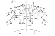
- FIG. 3 is an enlarged view showing a portion of the rotor 2 including the pseudo magnetic pole P2.
- the rotor core 20 has a slit group 8 including a plurality of slits 81 and 82 at the pseudo magnetic pole P2.
- the slit group 8 includes two first slits 81 closest to the magnetic pole center line of the pseudo magnetic pole P2 (indicated by CL in FIG. And two second slits 82 formed on both sides in the direction.
- the first slit 81 and the second slit 82 are formed symmetrically with respect to the magnetic pole center line CL of the pseudo magnetic pole P2. More specifically, the two first slits 81 are formed at positions symmetrical to each other with respect to the magnetic pole center line CL, and have shapes symmetrical to each other. The two second slits 82 are formed at positions symmetrical to each other with respect to the magnetic pole center line CL, and have shapes symmetrical to each other.
- one first slit 81 may be provided on the magnetic pole center line CL. This will be described in a second embodiment (FIGS. 12 and 13).
- the first slit 81 has a shape that is long in the radial direction. More specifically, the first slit 81 includes a radially outer end portion 81a, a radially inner end portion 81b, a circumferentially outer end portion (that is, a side farther from the magnetic pole center line CL) 81c, and a circumferentially outer end portion 81c. End 81d on the inner side in the direction (that is, on the side closer to the magnetic pole center line CL).
- the ends 81a and 81b of the first slit 81 extend perpendicular to the magnetic pole center line CL.
- the ends 81c and 81d extend parallel to the magnetic pole center line CL.
- the length A1 of the first slit 81 (that is, the interval between the ends 81a and 81b) is longer than the width H1 of the first slit 81 (that is, the interval between the ends 81c and 81d).
- the second slit 82 has a shape that is long in the radial direction. More specifically, the second slit 82 includes a radially outer end 82a, a radially inner end 82b, a circumferentially outer end (that is, a side farther from the magnetic pole center line CL) 82c, and a circumferentially outer end 82b. End 82d on the inner side in the direction (that is, on the side closer to the magnetic pole center line CL).
- the end 82a of the second slit 82 extends along the outer peripheral portion 20a, and the end 82b extends perpendicular to the magnetic pole center line CL.
- the ends 82c and 82d extend parallel to the magnetic pole center line CL.
- the length A2 of the second slit 82 (that is, the interval between the ends 82a and 82b) is longer than the width H2 of the second slit 82 (that is, the interval between the ends 82c and 82d).
- the length A1 of the first slit 81 is shorter than the length A2 of the second slit 82, and the width H1 of the first slit 81 is shorter than the width H2 of the second slit 82. That is, the sectional area of the first slit 81 is smaller than the sectional area of the second slit 82.
- a thin portion 83 is formed between the two first slits 81.
- the thin portion 83 has a width W1 that is the minimum width in the circumferential direction (that is, the minimum interval between the ends 81d of the two first slits 81).
- W1 the minimum width in the circumferential direction (that is, the minimum interval between the ends 81d of the two first slits 81).
- the width of the thin portion 83 is constant in the radial direction in FIG. 3, it is not always necessary to be constant. Since the thin portion 83 is located on the magnetic pole center line CL, it is also referred to as a pole center thin portion.
- a thin portion 84 is formed between the first slit 81 and the second slit 82.
- the thin portion 84 has a width W2 that is the minimum width in the circumferential direction (that is, the minimum distance between the end 81c of the first slit 81 and the side end 82d of the second slit 82).
- the width of the thin portion 84 is constant in the radial direction in FIG. 3, but is not necessarily constant.
- the thin portion 84 is also referred to as a thin portion between slits.
- a core region 85 is formed between the second slit 82 and the flux barrier 22.
- the core region 85 has a width W3 that is the minimum width in the circumferential direction between the second slit 82 and the end 22a of the flux barrier 22 closest to the magnetic pole center line CL.
- the shortest distance between the first slit 81 and the outer peripheral portion 20a (that is, the shortest distance between the end portion 81a of the first slit 81 and the outer peripheral portion 20a) is defined as a distance L1.
- the shortest distance between the second slit 82 and the outer peripheral portion 20a (that is, the shortest distance between the end portion 82a of the second slit 82 and the outer peripheral portion 20a) is defined as a distance L2.
- the distances L1 and L2 satisfy the relationship of L1 ⁇ L2.
- FIG. 4 is a schematic diagram showing a simulation result of magnetic flux passing through the pseudo magnetic pole P2 when the slits 81 and 82 are not provided in the pseudo magnetic pole P2.
- the magnetic flux emitted from the permanent magnet 25 of the magnetic pole P1 flows through the pseudo magnetic pole P2, and flows into the teeth 51 via the air gap 10.
- the magnetic flux that has flowed into the teeth 51 flows to the radially outer yoke 52, further flows to the adjacent teeth 51 radially inward, and returns to the permanent magnet 25.
- the magnetic flux passes through the portion where the magnetic resistance is low, and the magnetic resistance decreases as the magnetic path becomes shorter. Therefore, in the pseudo magnetic pole P2, the magnetic flux tends to concentrate in a region near the magnet magnetic pole P1 (that is, in a region near the gap M), and the magnetic flux flowing through the pole center of the pseudo magnetic pole P2 is relatively small.
- FIG. 5 is a schematic diagram showing a simulation result of magnetic flux passing through the pseudo magnetic pole P2 when the slits 81 and 82 are provided in the pseudo magnetic pole P2. If the slits 81 and 82 are provided in the pseudo magnetic pole P2, the magnetic resistance can be adjusted by using the magnetic saturation of the iron core portion, and thereby the distribution of the magnetic flux flowing through the pseudo magnetic pole P2 can be controlled. By providing the plurality of slits 81 and 82 symmetrically with respect to the magnetic pole center line CL, the magnetic flux distribution can be made symmetrical with respect to the magnetic pole center line CL.
- a magnetic flux is concentrated at the pole center of the pseudo magnetic pole P2, and a sinusoidal magnetic flux distribution in which the magnetic flux decreases toward the gap M can be obtained. That is, spatial harmonics of the surface magnetic flux of the rotor 2 can be suppressed, and torque ripple can be suppressed. Thereby, the noise of the electric motor 1 can be reduced.
- the distance L2 (FIG. 3) from the second slit 82 on the pole side where the magnetic flux is easily concentrated to the outer peripheral portion 20a is longer than the distance L1 (FIG. 3) from the first slit 81 to the outer peripheral portion 20a. Accordingly, it is possible to prevent the magnetic flux intensively flowing in the region close to the gap M from being blocked as much as possible. Thus, a decrease in magnetic flux linked to the coil 55 (FIG. 1) of the stator 5 can be suppressed, and a decrease in output of the electric motor 1 can be suppressed.
- FIG. 6 is a graph showing a comparison of the distribution of magnetic flux (hereinafter simply referred to as rotor magnetic flux) of the rotor 2 linked to the coil 55 in the electric motor 1 of the first embodiment and the electric motor of the comparative example.
- the vertical axis indicates the surface magnetic flux of the rotor 2
- the horizontal axis indicates the angle about the pole center of the pseudo magnetic pole P2.
- the motor of the comparative example has the same configuration as the motor 1 of the first embodiment except that the distances L1 and L2 between the slits 81 and 82 and the outer peripheral portion 20a satisfy L1> L2.
- the values of L1 and L2 are selected such that values obtained by dividing the longer distance by the shorter distance are substantially the same.
- the surface magnetic flux of the rotor 2 of the electric motor 1 of the first embodiment is higher than that of the electric motor of the comparative example. Further, it can be seen that the surface magnetic flux of the rotor 2 of the electric motor 1 of the first embodiment is higher than that of the electric motor of the comparative example, particularly at the pole center of the pseudo magnetic pole P2.
- the thin portion 83 between the two first slits 81 has the width W1.
- the thin portion 84 between the first slit 81 and the second slit 82 has a width W2.
- the core region 85 between the second slit 82 and the flux barrier 22 has a width W3.
- FIG. 7 is a graph showing the relationship between the ratio W3 / W2 of the width W3 of the core region 85 to the width W2 of the thin portion 84 and the surface magnetic flux of the rotor 2.
- FIG. 7 shows that the value of the surface magnetic flux of the rotor 2 becomes particularly high when W3 / W2 is in the range of 1 ⁇ W3 / W2 ⁇ 2.2.
- width W3 of the core region 85 is set to be equal to or larger than the width W2 of the thin portion 84 (that is, by 1 ⁇ W3 / W2), it is possible to prevent as much as possible the magnetic flux flowing intensively in the region close to the gap M. This is because it can be done. Also, by not making the width W2 of the thin portion 84 too narrow (ie, W3 / W2 ⁇ 2.2), it is possible to suppress an increase in the magnetic resistance of the thin portion 84.
- FIG. 8 is a graph showing the relationship between the ratio W3 / W1 of the width W3 of the core region 85 to the width W1 of the thin portion 83 and the surface magnetic flux of the rotor 2.
- FIG. 8 shows that when W3 / W1 is in the range of 1 ⁇ W3 / W1 ⁇ 2.1, the surface magnetic flux of the rotor 2 becomes particularly high.
- the width W3 of the core region 85 is set to be equal to or greater than the width W1 of the thin portion 84 (that is, 1 ⁇ W3 / W1), the magnetic flux flowing intensively in the region close to the gap M is prevented as much as possible. This is because it can be done. Also, by not making the width W1 of the thin portion 83 too narrow (that is, W3 / W1 ⁇ 2.1), it is possible to suppress an increase in the magnetic resistance of the thin portion 83.
- the width W3 of the core region 85 By setting the width W3 of the core region 85 to be equal to or greater than the sum (W1 + W2) of the widths W1 and W2 of the thin portions 83 and 84, the magnetic flux flowing in the region close to the gap between the poles M passes through the core region 85 and the pseudo magnetic pole P2. It becomes easier to flow to the pole center. Thereby, the effect of making the surface magnetic flux distribution of the rotor 2 close to a sine wave can be enhanced. Further, by suppressing a large decrease in the surface magnetic flux of the rotor 2, the magnetic flux linked to the coil 55 of the stator 5 is increased, and as a result, a decrease in the output of the electric motor 1 can be suppressed.
- the distance L2 between the second slit 82 and the outer peripheral portion 20a of the rotor 2 is equal to or greater than the sum (W1 + W2) of the widths W1 and W2 of the thin portions 83, 83, in other words, W1 + W2 ⁇ L2. desirable.
- a magnetic path (indicated by a symbol S in FIG. 3) from the core region 85 to the outer peripheral side of the second slit 82 is smaller than a magnetic path toward the pole center of the pseudo magnetic pole P2 via the thin portions 83 and 84.
- the magnetic path going to the pole center of the pseudo magnetic pole P2 via the relay becomes wide, and the magnetic resistance decreases. Therefore, the effect of bringing the surface magnetic flux distribution of the rotor 2 closer to a sine wave can be enhanced. Further, by suppressing a large decrease in the surface magnetic flux of the rotor 2, the magnetic flux linked to the coil 55 of the stator 5 is increased, and as a result, a decrease in the output of the electric motor 1 can be suppressed.
- FIG. 9 is an enlarged view of a portion of the rotor 2 including the pseudo magnetic pole P2. 8
- the circumferential length of the thin portion 84 between the first slit 81 and the second slit 82 is defined as a length T1. It is desirable that the length T1 is equal to or larger than the circumferential width H2 of the second slit 82 (that is, T1 ⁇ H2).
- the width H2 of the second slit 82 is equal to the length of the magnetic path S radially outside the second slit 82.
- the magnetic flux density reaches a magnetic saturation state of, for example, 1.6T
- the magnetic flux is magnetically saturated at the shorter length. Flow through the magnetic path. Therefore, when the length T1 of the thin portion 84 is longer than the width H2 of the second slit 82, the magnetic flux flows through the magnetic path S radially outside the second slit 82 more than the thin portion 84.
- the magnetic flux flowing in the region close to the gap M can be guided from the magnetic path S radially outside the second slit 82 to the pole center of the pseudo magnetic pole P2.
- the effect of bringing the surface magnetic flux distribution of the rotor 2 closer to a sine wave can be enhanced, and the output of the electric motor 1 can be suppressed from being reduced.
- FIG. 10 is a view for explaining the radial positions of the slits 81 and 82 in the rotor 2. It is desirable that the shortest distance D1 from the center axis C1 of the rotor 2 to the magnet insertion hole 21 is longer than the shortest distance D2 from the center axis C1 to the second slit 82 (that is, D1> D2 is satisfied).
- the magnetic flux from the permanent magnet 25 flows from the radially inner end of the magnet insertion hole 21 toward the pseudo magnetic pole P2.
- the permanent magnet 25 and the thin portion 84 are connected. Since the first slit 81 does not exist on the magnetic path connecting the shortest, most of the magnetic flux from the permanent magnet 25 flows into the thin portion 84.
- the magnetic flux flowing into the thin portion 84 decreases, the magnetic flux passing through the core region 85 increases, and as a result, the magnetic flux flowing from the magnetic path S radially outside the second slit 82 toward the pole center of the pseudo magnetic pole P2 increases. I do.
- the effect of bringing the surface magnetic flux distribution of the rotor 2 closer to a sine wave can be enhanced, and the output of the electric motor 1 can be suppressed from decreasing.
- FIG. 11 is a longitudinal sectional view showing a molded electric motor to which the electric motor 1 of the first embodiment is applied.
- the stator 5 is covered with a mold resin part 60 to form a mold stator 6.
- the mold resin part 60 is made of, for example, a thermosetting resin such as BMC (bulk molding compound).
- the mold resin portion 60 has an opening 62 on the left side (load side described later) in FIG. 11, and has a bearing support 61 on the opposite side (opposite load side described later).
- the rotor 3 is inserted from the opening 62 into a hollow portion inside the stator 5.
- the metal bracket 15 is attached to the opening 62 of the mold resin part 60.
- the bracket 15 holds one bearing 12 that supports the rotating shaft 11.
- a cap 14 is attached to the outside of the bracket 15 to prevent water or the like from entering the bearing 12.
- the bearing support 61 holds another bearing 13 that supports the rotating shaft 11.
- the rotating shaft 11 protrudes from the stator 5 to the left in FIG. 11, and an impeller of a blower, for example, is attached to the tip 11a. Therefore, the protruding side (the left side in FIG. 11) of the rotating shaft 11 is referred to as “load side”, and the opposite side (the right side in FIG. 11) is referred to as “anti-load side”.
- the substrate 7 is disposed on the non-load side of the stator 5. On the substrate 7, a magnetic sensor 71 and a drive circuit 72 for driving the electric motor 1 are mounted.
- the magnetic sensor 71 is arranged so as to face the sensor magnet 26 attached to the rotor 2.
- the drive circuit 72 can be provided outside the electric motor 1 instead of on the substrate 7.
- Lead wires 73 are wired on the substrate 7.
- the lead wires 73 include a power supply lead wire for supplying power to the coil 55 of the stator 5 and a sensor lead wire for transmitting a signal of the magnetic sensor 71 to the outside.
- a lead wire outlet component 74 for leading the lead wire 73 to the outside is attached to the outer peripheral portion of the mold resin portion 60.
- the resin portion 4 described above is provided on the inner peripheral side of the rotor core 20, but also covers both end surfaces in the axial direction of the rotor core 20. Further, it is desirable that a part of the resin portion 4 enters the inside of the magnet insertion hole 31. Thus, the permanent magnet 25 can be prevented from falling out of the magnet insertion hole 21.
- An annular sensor magnet (position detecting magnet) 36 is attached to the rotor core 20.
- the sensor magnet 26 is disposed on the side facing the substrate 7 in the axial direction of the rotor core 20, and is surrounded and held by the resin portion 4.
- the sensor magnets 26 have the same number of magnetic poles as the number of poles of the rotor 2 and are arranged at equal intervals in the circumferential direction.
- the magnetization direction of the sensor magnet 26 is the axial direction, but is not limited to this.
- the magnetic sensor 71 is formed of, for example, a Hall IC, and is arranged to face the sensor magnet 26 of the rotor 2.
- the magnetic sensor 71 detects a position in the circumferential direction of the rotor 2 (that is, a rotational position) based on a change in magnetic flux (N / S) from the sensor magnet 26, and outputs a detection signal.
- the magnetic sensor 71 is not limited to the Hall IC, but may be an MR element (Magneto-Resistive) element, a GMR (Giant-Magneto-Resistive) element, or a magnetic impedance element.
- the detection signal of the magnetic sensor 71 is output to the drive circuit 72.
- a detection signal of the magnetic sensor 71 is output to the drive circuit 72 via a sensor lead.
- the drive circuit 72 controls the current flowing through the coil 55 according to the relative rotation position of the rotor 2 with respect to the stator 5 based on the detection signal from the magnetic sensor 71.
- stator 5 is covered with the mold resin portion 60
- a configuration in which the stator 5 is fixed to the inside of the shell by shrink fitting may be adopted.
- the rotor 2 of the first embodiment includes the magnet magnetic pole P1 (that is, the first magnetic pole) constituted by the permanent magnet 25 and the pseudo magnetic pole P2 (that is, the second magnetic pole) constituted by the rotor core 20. ) And a plurality of slits 81 and 82 in the pseudo magnetic pole P2, the slits 81 and 82 are formed symmetrically with respect to the magnetic pole center line CL of the pseudo magnetic pole P2, and the first slit 81 (that is, the first slit 81) is formed.
- the distance L1 from the slit) to the outer peripheral portion 20a of the rotor core 20 and the distance L2 from the second slit 82 (that is, the second slit) to the outer peripheral portion 20a of the rotor core 20 satisfy L1 ⁇ L2. Thereby, the magnetic flux flowing from the region close to the gap M toward the pole center of the pseudo magnetic pole P2 can be increased.
- the surface magnetic flux distribution of the rotor 2 can be approximated to a sine wave in which the magnetic flux is concentrated at the pole center and the magnetic flux decreases toward the gap M.
- spatial harmonics of the surface magnetic flux of the rotor 2 can be suppressed, and torque ripple can be suppressed. That is, the noise of the electric motor 1 can be reduced.
- the magnetic flux linked to the coil 55 of the stator 5 increases, it is possible to suppress a decrease in the output of the electric motor 1 due to the provision of the slits 81 and 82.
- the magnetic flux can be guided to the pole center of the pseudo magnetic pole P2 via the thin portion 83 between the two first slits 81.
- the circumferential interval (that is, the width of the thin portion 83) W1 between the two first slits 81 and the circumferential interval (that is, the width of the core region 85) W3 between the second slit 82 and the magnet insertion hole 21 are equal to each other. Since 1 ⁇ W3 / W1 ⁇ 2 is satisfied, it is possible to prevent the magnetic flux flowing in the region near the gap M from being interrupted as much as possible, thereby suppressing a decrease in the output of the electric motor 1.
- a circumferential interval that is, the width of the thin portion 83
- W1 between the two first slits 81 a circumferential interval (that is, a width of the thin portion 84) W2 between the slits 81 and 82, the second slit 82, and the magnet
- the circumferential distance W3 from the insertion hole 21 that is, the width of the core region 85
- W1 + W2 ⁇ W3 the magnetic flux easily flows through the core region 85 to the pole center of the pseudo magnetic pole P2. Therefore, the effect of bringing the surface magnetic flux distribution of the rotor 2 closer to a sine wave can be enhanced, and the output of the electric motor 1 can be suppressed from being reduced.
- the circumferential interval (ie, the width of the thin portion 84) W2 between the slits 81 and 82 and the circumferential interval (ie, the width of the core region 85) W3 between the second slit 82 and the magnet insertion hole 21 are: Since 1 ⁇ W3 / W2 ⁇ 2.2 is satisfied, it is possible to prevent the magnetic flux flowing in the region close to the gap M from being interrupted as much as possible, thereby suppressing a decrease in the output of the electric motor 1.
- the magnetic flux is smaller than that of the thin portion 84.
- a large amount of the magnetic flux flows through the magnetic path S radially outside the second slit 82.
- the resin portion 4 made of a non-magnetic material is provided between the rotating shaft 11 and the rotor core 20, leakage magnetic flux from the rotor core 20 to the rotating shaft 11 can be suppressed.
- the resin portion 4 is provided between the rotor core 20 and the rotating shaft 11 here, the rotating shaft 11 may be fixed to the center hole of the rotor core 20 instead of providing the resin portion 4.
- Embodiment 2 FIG. Next, a second embodiment of the present invention will be described.
- the electric motor of the second embodiment differs from the electric motor 1 of the first embodiment in the configuration of the rotor 2A.
- the stator of the electric motor according to the second embodiment has the same configuration as the stator 5 of the electric motor 1 according to the first embodiment.
- FIG. 12 is a sectional view showing a rotor 2A according to the second embodiment.
- the rotor 2A has a cylindrical rotor core 200 centered on the central axis C1.
- the rotor core 200 is formed by laminating a plurality of laminated elements having a thickness of 0.2 to 0.5 mm and having magnetism in the axial direction, and fixing them by caulking or the like.
- the laminated element is an electromagnetic steel sheet mainly containing iron.
- the rotor core 200 may be formed of a resin core obtained by combining a soft magnetic material and a resin.
- the diameter of the rotor 2A is 50 mm.
- a plurality of magnet insertion holes 21 are formed along the outer periphery of the rotor core 200.
- the number of the magnet insertion holes 21 is five.
- a permanent magnet 25 is arranged in each magnet insertion hole 21.
- the shape and arrangement of the magnet insertion holes 21 are as described in the first embodiment.
- the material and shape of the permanent magnet 25 are as described in the first embodiment.
- a magnet magnetic pole P1 is formed by the permanent magnet 25 arranged in each magnet insertion hole 21. Further, a pseudo magnetic pole P2 having a polarity opposite to that of the permanent magnet 25 is formed between the adjacent permanent magnets 25 in the rotor core 200. That is, the rotor 2A has five magnet magnetic poles P1 and five pseudo magnetic poles P2 alternately in the circumferential direction. Therefore, the number of poles of the rotor 2A is ten. However, the number of poles of the rotor 2A is not limited to 10 poles.
- the rotor core 200 has a center hole 28 at the center in the radial direction, and the rotating shaft 11 is fixed to the center hole 28. That is, rotor 2A of the second embodiment does not have resin portion 4 (FIG. 1) described in the first embodiment.
- the material and shape of the rotating shaft 11 are as described in the first embodiment.
- the air hole 27 is provided radially inside the magnet insertion hole 21 of the rotor core 200, but the air hole 27 may not be provided.
- the outer periphery of rotor core 200 has the shape of a flower circle described in the first embodiment. That is, the outer circumference of the rotor core 200 has an outer circumference 20a centered on the pole center of each magnetic pole (magnet magnetic pole P1 and pseudo magnetic pole P2) and an outer circumference 20b centered on the gap M.
- the outer peripheral portions 20a and 20b are arc-shaped portions each having a center of curvature on the central axis C1 side, but have different radii of curvature.
- the magnet insertion hole 21 has the flux barriers 22 described in the first embodiment at both ends in the circumferential direction. Although the flux barriers 22 are arranged at both ends in the circumferential direction of the magnet insertion hole 21 here, they may be arranged only at one end of the magnet insertion hole 21 in the circumferential direction.
- FIG. 13 is an enlarged view of a portion including the pseudo magnetic pole P2 of the rotor 2A.
- the rotor core 200 has a slit group 8 including a plurality of slits 81 and 82 at the pseudo magnetic pole P2.
- the slit group 8 includes one first slit 81 located on the magnetic pole center line CL of the pseudo magnetic pole P2, and two first slits 81 formed on both sides of the first slit 81 in the circumferential direction. And a second slit 82.
- the first slit 81 and the second slit 82 are formed symmetrically with respect to the magnetic pole center line CL of the pseudo magnetic pole P2. More specifically, the first slit 81 is formed such that its circumferential center is located on the magnetic pole center line CL, and has a shape symmetrical with respect to the magnetic pole center line CL. The two second slits 82 are formed at symmetric positions with respect to the magnetic pole center line CL, and have mutually symmetric shapes.
- the first slit 81 has a shape that is long in the radial direction. More specifically, the first slit 81 has a radially outer end 81a, a radially inner end 81b, and circumferentially opposite ends 81c and 81d.
- the ends 81a and 81b of the first slit 81 extend perpendicular to the magnetic pole center line CL.
- the ends 81c and 81d extend parallel to the magnetic pole center line CL.
- the length S1 of the first slit 81 (that is, the interval between the ends 81a and 81b) is longer than the width H1 of the first slit 81 (that is, the interval between the ends 81c and 81d).
- the second slit 82 has a shape that is long in the radial direction. More specifically, the second slit 82 includes a radially outer end 82a, a radially inner end 82b, a circumferentially outer end (that is, a side farther from the magnetic pole center line CL) 82c, and a circumferentially outer end 82b. End 82d on the inner side in the direction (that is, on the side closer to the magnetic pole center line CL).
- the end 82a of the second slit 82 extends along the outer peripheral portion 20a, and the end 82b extends perpendicular to the magnetic pole center line CL.
- the ends 82c and 82d extend parallel to the magnetic pole center line CL.
- the length A2 of the second slit 82 (that is, the interval between the ends 82a and 82b) is longer than the width H2 of the second slit 82 (that is, the interval between the ends 82c and 82d).
- Both the length A1 and the width H1 of the first slit 81 are shorter than the length A2 and the width H2 of the second slit 82. That is, the sectional area of the first slit 81 is smaller than the sectional area of the second slit 82.
- a thin portion 84 is formed between the first slit 81 and the second slit 82.
- the thin portion 84 has a minimum width W2 in the circumferential direction (that is, a minimum interval between the end 81c of the first slit 81 and the side end 82d of the second slit 82).
- the width W2 of the thin portion 84 is constant in the radial direction in FIG. 13, the width W2 is not necessarily constant.
- a core region 85 is formed between the second slit 82 and the flux barrier 22.
- the core region 85 has a width W3 that is the minimum width in the circumferential direction between the second slit 82 and the end of the flux barrier 22 closest to the magnetic pole center line CL.
- the shortest distance between the first slit 81 and the outer peripheral portion 20a (that is, the shortest distance between the end portion 81a of the first slit 81 and the outer peripheral portion) is defined as a distance L1.
- the shortest distance between the second slit 82 and the outer peripheral portion 20a (that is, the shortest distance between the end portion 82a of the second slit 82 and the outer peripheral portion 20a) is defined as a distance L2.
- the distances L1 and L2 satisfy the relationship of L1 ⁇ L2.
- the distance between the rotor 2A and the stator 5 is minimized at the pole centers of the magnetic poles (magnet poles P1 and pseudo magnetic poles P2), and increases with distance from the pole centers. And the magnetic flux distribution on the surface of the rotor 2A approaches a sine wave.
- the region closer to the gap M is directed toward the pole center of the pseudo magnetic pole P2.
- the flowing magnetic flux can be increased.
- the surface magnetic flux distribution of the rotor 2A can be approximated to a sine wave, and spatial harmonics can be suppressed. Thereby, torque ripple can be suppressed and noise of the electric motor 1 can be reduced.
- the magnetic flux linked to the coil 55 (FIG. 1) of the stator 5 is increased, and the output of the electric motor 1 is reduced. Can be suppressed. That is, the noise of the electric motor 1 can be reduced, and the output can be prevented from lowering.
- the dimensions of the thin portion 84 and the core region 85 will be described.
- the thin portion 84 between the first slit 81 and the second slit 82 has the width W2.
- the core region 85 between the second slit 82 and the flux barrier 22 has a width W3.
- the surface magnetic flux of the rotor 2A is particularly high. That is, by setting the width W3 of the core region 85 to be equal to or greater than the width W2 of the thin portion 84, it is possible to prevent the magnetic flux flowing in the region close to the gap M from being blocked as much as possible. Further, by not making the width W2 of the thin portion 84 too narrow, an increase in the magnetic resistance of the thin portion 84 can be suppressed.
- the distance L2 between the second slit 82 and the outer peripheral portion 20a of the rotor 2A is equal to or greater than the width W2 of the thin portion 84 (that is, W2 ⁇ L2).
- the circumferential length of the thin portion 84 between the first slit 81 and the second slit 82 is defined as a length T1. It is desirable that the length T1 is equal to or larger than the circumferential width H2 of the second slit 82 (that is, T1 ⁇ H2).
- the magnetic flux is reduced to the shorter magnetically saturated length. Flows through the magnetic path. Therefore, when the length T1 of the thin portion 84 is longer than the width H2 of the second slit 82, the magnetic flux flows through the magnetic path S radially outside the second slit 82 more than the thin portion 84. Thus, the magnetic flux flowing in the region near the gap M can be guided from the magnetic path S radially outside the second slit 82 to the pole center of the pseudo magnetic pole P2. As a result, the effect of bringing the surface magnetic flux distribution of the rotor 2A closer to a sine wave can be enhanced, and the magnetic force can be prevented from lowering.
- the shortest distance D1 from the center axis C1 of the rotor 2A to the magnet insertion hole 21 is longer than the shortest distance D2 from the center axis C1 to the second slit 82 (that is, D1> D2 is satisfied). Accordingly, the second slit 82 exists in the magnetic path connecting the permanent magnet 25 and the thin portion 84 in the shortest distance, and serves as a magnetic barrier. Therefore, the magnetic flux coming out of the permanent magnet 25 and flowing into the thin portion 84 decreases.
- the magnetic flux flowing into the thin portion 84 decreases, the magnetic flux passing through the core region 85 increases, and as a result, the magnetic flux flowing from the magnetic path S radially outside the second slit 82 toward the pole center of the pseudo magnetic pole P2 increases. I do. As a result, the effect of bringing the surface magnetic flux distribution of the rotor 2A closer to a sine wave can be enhanced, and a decrease in magnetic force can be suppressed.
- the rotor 2A has three slits 81 and 82, and the first slit 81 is located on the magnetic pole center line CL.
- the distance L1 from the first slit 81 (ie, the first slit) to the outer peripheral portion 20a of the rotor core 200 and the distance L2 from the second slit 82 (ie, the second slit) to the outer peripheral portion 20a of the rotor core 200 are L1 ⁇ Satisfies L2.
- the surface magnetic flux distribution of the rotor 2A can be approximated to a sine wave.
- spatial harmonics of the surface magnetic flux of the rotor 2A can be suppressed, and torque ripple can be suppressed. That is, the noise of the electric motor 1 can be reduced.
- the magnetic flux linked to the coil 55 of the stator 5 increases, it is possible to suppress a decrease in magnetic force due to the provision of the slits 81 and 82.
- the resin portion 4 is provided between the rotor core 200 and the rotary shaft 11. (FIG. 1) may be provided.
- the first embodiment four slits are provided in the pseudo magnetic pole P2, and in the second embodiment, three slits are provided. However, five or more slits may be provided.
- FIG. 14A is a diagram illustrating a configuration of an air conditioner 500 to which the electric motor of each embodiment can be applied.
- the air conditioner 500 includes an outdoor unit 501, an indoor unit 502, and a refrigerant pipe 503 connecting these.
- the outdoor unit 501 includes a blower (outdoor blower) 510.
- FIG. 14B is a cross-sectional view taken along line 14B-14B shown in FIG.
- the outdoor unit 501 has a housing 508 and a frame 509 fixed inside the housing 508.
- the electric motor 1 as a drive source of the blower 510 is fixed to the frame 509.
- An impeller (blade portion) 511 is attached to the rotating shaft 11 of the electric motor 1 via a hub 512.
- FIG. 15 is a schematic diagram showing a refrigerant circuit of the air conditioner 500.
- the air conditioner 500 includes a compressor 504, a condenser 505, a throttle device (decompression device) 506, and an evaporator 507.
- the compressor 504, the condenser 505, the expansion device 506, and the evaporator 507 are connected by a refrigerant pipe 503 to form a refrigeration cycle. That is, the refrigerant circulates in the order of the compressor 504, the condenser 505, the expansion device 506, and the evaporator 507.
- the compressor 504, the condenser 505, and the expansion device 506 are provided in the outdoor unit 501.
- the evaporator 507 is provided in the indoor unit 502.
- the indoor unit 502 is provided with a blower (indoor blower) 520 for supplying indoor air to the evaporator 507.
- the operation of the air conditioner 500 is as follows.
- the compressor 504 compresses and sends out the sucked refrigerant.
- the condenser 505 exchanges heat between the refrigerant flowing from the compressor 504 and the outdoor air, condenses and liquefies the refrigerant, and sends it to the refrigerant pipe 503.
- the blower 510 of the outdoor unit 501 discharges the heat released when the refrigerant is condensed in the condenser 505 to the outside.
- the expansion device 506 adjusts the pressure and the like of the refrigerant flowing through the refrigerant pipe 503.
- the evaporator 507 performs heat exchange between the refrigerant brought into a low pressure state by the expansion device 506 and the indoor air, causes the refrigerant to deprive the heat of the air, evaporates (vaporizes), and sends the refrigerant to the refrigerant pipe 503.
- the blower 520 of the indoor unit 502 supplies indoor air to the evaporator 507.
- the cool air whose heat has been removed by the evaporator 507 is supplied indoors.
- the electric motor 1 is configured to suppress the demagnetization of the permanent magnet 25. Therefore, by using the electric motor 1 as a power source of the blower 510, the operation efficiency of the air conditioner 500 can be improved over a long period of time, and energy consumption can be reduced.
- the electric motor 1 of each embodiment is used as a drive source of the blower (outdoor blower) 510, but may be used as a drive source of the blower (indoor blower) 520. Further, the electric motor 1 of each embodiment is not limited to a blower, and may be used as a drive source of the compressor 504, for example.
- the electric motor 1 of each embodiment is not limited to the air conditioner 500, and may be used, for example, as an electric motor for a ventilation fan, a home appliance, or a machine tool.
Landscapes
- Engineering & Computer Science (AREA)
- Power Engineering (AREA)
- Permanent Field Magnets Of Synchronous Machinery (AREA)
- Iron Core Of Rotating Electric Machines (AREA)
Abstract
Description
<電動機の構成>
図1は、実施の形態1の電動機1を示す断面図である。電動機1は、回転可能なロータ2と、ロータ2を囲むように設けられた環状のステータ5とを備えたインナロータ型の電動機である。電動機1は、また、ロータ2に永久磁石25を埋め込んだ永久磁石埋込型電動機でもある。ステータ5とロータ2との間には、例えば0.4mmのエアギャップ(空隙)10が設けられている。
ステータ5は、ステータコア50と、ステータコア50に巻き付けられたコイル55とを有する。ステータコア50は、例えば厚さが0.2mm~0.5mmの磁性を有する積層要素を軸方向に複数枚積層し、カシメ等により固定したものである。積層要素は、ここでは、鉄(Fe)を主成分とする電磁鋼板である。
図2は、ロータコア20および永久磁石25を示す断面図である。図2では、樹脂部4および回転シャフト11を省略している。ロータ2は、中心軸C1を中心とする円筒状のロータコア20を有する。ロータコア20は、厚さ0.2~0.5mmの磁性を有する積層要素を軸方向に複数枚積層し、カシメ等により固定したものである。積層要素は、ここでは、鉄を主成分とする電磁鋼板である。なお、ロータコア20は、軟磁性材料と樹脂とを組み合わせた樹脂鉄心で構成してもよい。ロータ2の直径は、ここでは50mmである。
次に、実施の形態1の作用について説明する。ロータ2の表面(すなわち外周面)における磁束分布を正弦波に近づけるためには、ロータ2とステータ5との間隔を周方向に変化させることが有効である。ロータ2とステータ5との間隔が各磁極(磁石磁極P1および疑似磁極P2)の極中心で最小になり、極中心から離れるほど大きくなるように構成すれば、極中心に磁束が集中し、ロータ2の表面磁束分布が正弦波に近づく。
図11は、この実施の形態1の電動機1を適用したモールド電動機を示す縦断面図である。ステータ5は、モールド樹脂部60によって覆われ、モールドステータ6を構成している。
以上説明したように、この実施の形態1のロータ2は、永久磁石25によって構成される磁石磁極P1(すなわち第1の磁極)と、ロータコア20によって構成される疑似磁極P2(すなわち第2の磁極)とを有すると共に、疑似磁極P2に複数のスリット81,82を有し、スリット81,82が疑似磁極P2の磁極中心線CLに対して対称に形成され、第1スリット81(すなわち第1のスリット)からロータコア20の外周部20aまでの距離L1と、第2スリット82(すなわち第2のスリット)からロータコア20の外周部20aまでの距離L2とが、L1<L2を満足する。これにより、極間Mに近い領域から疑似磁極P2の極中心に向かって流れる磁束を増加させることができる。
次に、本発明の実施の形態2について説明する。実施の形態2の電動機は、ロータ2Aの構成において、実施の形態1の電動機1と異なるものである。実施の形態2の電動機のステータは、実施の形態1の電動機1のステータ5と同様に構成されている。
図12は、実施の形態2のロータ2Aを示す断面図である。ロータ2Aは、中心軸C1を中心とする円筒状のロータコア200を有する。ロータコア200は、厚さ0.2~0.5mmの磁性を有する積層要素を軸方向に複数枚積層し、カシメ等により固定したものである。積層要素は、ここでは、鉄を主成分とする電磁鋼板である。なお、ロータコア200は、軟磁性材料と樹脂とを組み合わせた樹脂鉄心で構成してもよい。ロータ2Aの直径は、ここでは50mmである。
次に、実施の形態2の作用について説明する。実施の形態1でも説明したように、ロータ2Aとステータ5との間隔が各磁極(磁石磁極P1および疑似磁極P2)の極中心で最小になり、極中心から離れるほど大きくなる構成により、極中心に磁束が集中し、ロータ2Aの表面磁束分布が正弦波に近づく。
以上説明したように、実施の形態2では、ロータ2Aのスリット81,82が3つであり、第1スリット81が磁極中心線CL上に位置しているが、実施の形態1と同様、第1スリット81(すなわち第1のスリット)からロータコア200の外周部20aまでの距離L1と、第2スリット82(すなわち第2のスリット)からロータコア200の外周部20aまでの距離L2とが、L1<L2を満足する。これにより、極間Mに近い領域から疑似磁極P2の極中心に向かって流れる磁束を増加させることができる。
次に、上述した各実施の形態の電動機を適用した空気調和装置について説明する。図14(A)は、各実施の形態の電動機が適用可能な空気調和装置500の構成を示す図である。空気調和装置500は、室外機501と、室内機502と、これらを接続する冷媒配管503とを備える。室外機501は、送風機(室外送風機)510を備えている。
Claims (14)
- 中心軸を囲む環状の外周と、前記外周に沿って形成された磁石挿入孔とを有するロータコアと、
前記磁石挿入孔に配置された永久磁石と
を有し、
前記永久磁石によって第1の磁極が構成され、前記ロータコアの一部によって第2の磁極が構成され、
前記ロータコアは、前記第2の磁極に複数のスリットを有し、
前記複数のスリットは、前記第2の磁極の極中心と前記中心軸とを結ぶ磁極中心線に対して対称に形成され、
前記複数のスリットは、前記中心軸を中心とする周方向における前記磁極中心線の一方の側に、前記磁極中心線に最も近い第1のスリットと、前記第1のスリットに対して前記周方向に隣接する第2のスリットとを有し、
前記第1のスリットから前記ロータコアの外周までの最短距離L1と、
前記第2のスリットから前記ロータコアの前記外周までの最短距離L2とが、
L1<L2を満足する
ロータ。 - 前記第1のスリットは、前記磁極中心線上に形成されている
請求項1に記載のロータ。 - 前記磁極中心線に対する前記周方向の他方の側に、前記磁極中心線に対して前記第1のスリットと対称に形成されたもう1つの第1のスリットを有する
請求項1に記載のロータ。 - 前記第1のスリットと前記もう1つの第1のスリットとの前記周方向の間隔W1と、
前記第2のスリットと前記磁石挿入孔との前記周方向の間隔W3とが、
1≦W3/W1≦2.1
を満足する
請求項3に記載のロータ。 - 前記第1のスリットと前記もう1つの第1のスリットとの前記周方向の間隔W1と、
前記第1のスリットと前記第2のスリットとの前記周方向の間隔W2と、
前記第2のスリットと前記磁石挿入孔との前記周方向の間隔W3とが、
W1+W2<W3を満足する
請求項3または4に記載のロータ。 - 前記間隔W1と、前記間隔W2と、前記最短距離L2とが、
W1+W2<L2を満足する
請求項4または5に記載のロータ。 - 前記第1のスリットと前記第2のスリットとの前記周方向の間隔W2と、
前記第2のスリットと前記磁石挿入孔との前記周方向の間隔W3とが、
1≦W3/W2≦2.2
を満足する
請求項1から6までの何れか1項に記載のロータ。 - 前記ロータコアは、前記第1のスリットと前記第2のスリットとの間に薄肉部を有し、
前記薄肉部の前記中心軸を中心とする径方向の長さT1と、
前記第2のスリットの前記周方向の幅H2とが、
T1>H2
を満足する
請求項1から7までの何れか1項に記載のロータ。 - 前記中心軸から前記磁石挿入孔までの最短距離が、前記中心軸から前記第2のスリットまでの最短距離よりも長い
請求項1から8までの何れか1項に記載のロータ。 - 前記ロータコアの外周は、前記第1の磁極の極中心を通って延在する第1の外周部と、前記第2の磁極の極中心を通って延在する第2の外周部と、前記第1の外周部と前記第2の外周部との間に形成された第3の外周部とを有し、
前記中心軸から前記第3の外周部までの最長距離は、前記中心軸から前記第1の外周部までの最長距離よりも短く、前記中心軸から前記第2の外周部までの最長距離よりも短い
請求項1から9までの何れか1項に記載のロータ。 - 回転シャフトと、
前記回転シャフトと前記ロータコアとの間に設けられ、非磁性材料で形成された支持部と
を備えた請求項1から10までの何れか1項に記載のロータ。 - 請求項1から11までの何れか1項に記載のロータと、
前記ロータを、前記中心軸を中心とする径方向の外側から囲むステータと
を備えた電動機。 - 請求項12に記載の電動機と、
前記電動機によって回転する羽根部と
を備えた送風機。 - 室外機と、室内機と、前記室外機と前記室内機とを連結する冷媒配管とを備え、
前記室外機および前記室内機の少なくとも一方は、請求項13に記載の送風機を有する
空気調和装置。
Priority Applications (7)
| Application Number | Priority Date | Filing Date | Title |
|---|---|---|---|
| CN201880094457.XA CN112262516B (zh) | 2018-06-25 | 2018-06-25 | 转子、电动机、送风机及空调装置 |
| KR1020247000458A KR20240007721A (ko) | 2018-06-25 | 2018-06-25 | 로터, 전동기, 송풍기 및 공기 조화 장치 |
| KR1020207036096A KR20210011954A (ko) | 2018-06-25 | 2018-06-25 | 로터, 전동기, 송풍기 및 공기 조화 장치 |
| PCT/JP2018/023964 WO2020003341A1 (ja) | 2018-06-25 | 2018-06-25 | ロータ、電動機、送風機および空気調和装置 |
| EP18924914.7A EP3813231A4 (en) | 2018-06-25 | 2018-06-25 | ROTOR, ELECTRIC MOTOR, FAN AND AIR CONDITIONING |
| US17/056,852 US11552515B2 (en) | 2018-06-25 | 2018-06-25 | Rotor, motor, fan, and air conditioner |
| JP2019537194A JP6964672B2 (ja) | 2018-06-25 | 2018-06-25 | ロータ、電動機、送風機および空気調和装置 |
Applications Claiming Priority (1)
| Application Number | Priority Date | Filing Date | Title |
|---|---|---|---|
| PCT/JP2018/023964 WO2020003341A1 (ja) | 2018-06-25 | 2018-06-25 | ロータ、電動機、送風機および空気調和装置 |
Publications (1)
| Publication Number | Publication Date |
|---|---|
| WO2020003341A1 true WO2020003341A1 (ja) | 2020-01-02 |
Family
ID=68986127
Family Applications (1)
| Application Number | Title | Priority Date | Filing Date |
|---|---|---|---|
| PCT/JP2018/023964 WO2020003341A1 (ja) | 2018-06-25 | 2018-06-25 | ロータ、電動機、送風機および空気調和装置 |
Country Status (6)
| Country | Link |
|---|---|
| US (1) | US11552515B2 (ja) |
| EP (1) | EP3813231A4 (ja) |
| JP (1) | JP6964672B2 (ja) |
| KR (2) | KR20240007721A (ja) |
| CN (1) | CN112262516B (ja) |
| WO (1) | WO2020003341A1 (ja) |
Cited By (10)
| Publication number | Priority date | Publication date | Assignee | Title |
|---|---|---|---|---|
| JPWO2021161421A1 (ja) * | 2020-02-12 | 2021-08-19 | ||
| WO2021171420A1 (ja) * | 2020-02-26 | 2021-09-02 | 三菱電機株式会社 | 回転子、電動機、送風機、空気調和装置、及び回転子の製造方法 |
| WO2021171554A1 (ja) * | 2020-02-28 | 2021-09-02 | 三菱電機株式会社 | 電動機、送風機および空気調和装置 |
| WO2021171476A1 (ja) * | 2020-02-27 | 2021-09-02 | 三菱電機株式会社 | 電動機、ファン、及び空気調和機 |
| WO2021171474A1 (ja) * | 2020-02-27 | 2021-09-02 | 三菱電機株式会社 | コンシクエントポール型ロータ、電動機、ファン、及び空気調和機 |
| US20220247297A1 (en) * | 2021-02-03 | 2022-08-04 | Okuma Corporation | Linear motor |
| WO2023073757A1 (ja) | 2021-10-25 | 2023-05-04 | 三菱電機株式会社 | ロータ、電動機、送風機および空気調和装置 |
| WO2023148953A1 (ja) * | 2022-02-07 | 2023-08-10 | 三菱電機株式会社 | ロータ、電動機、送風機、空気調和装置および電動機の製造方法 |
| WO2023162331A1 (ja) * | 2022-02-24 | 2023-08-31 | パナソニックIpマネジメント株式会社 | ロータ及び電動機 |
| JP7527469B2 (ja) | 2021-03-11 | 2024-08-02 | 三菱電機株式会社 | ロータ、電動機、送風機、空気調和装置およびロータの製造方法 |
Families Citing this family (3)
| Publication number | Priority date | Publication date | Assignee | Title |
|---|---|---|---|---|
| CN115241999A (zh) * | 2018-01-18 | 2022-10-25 | 美蓓亚三美株式会社 | 定子构造以及旋转变压器 |
| JP1665117S (ja) * | 2020-02-27 | 2020-08-03 | ||
| JP1665115S (ja) * | 2020-02-27 | 2020-08-03 |
Citations (4)
| Publication number | Priority date | Publication date | Assignee | Title |
|---|---|---|---|---|
| JP2004346757A (ja) * | 2003-05-20 | 2004-12-09 | Daikin Ind Ltd | 圧縮機および空気調和装置 |
| JP2012244783A (ja) | 2011-05-19 | 2012-12-10 | Mitsubishi Electric Corp | 磁石埋め込み型回転子、電動機、圧縮機、空気調和機、および、電気自動車 |
| WO2015045999A1 (ja) * | 2013-09-26 | 2015-04-02 | 三菱電機株式会社 | 永久磁石埋込型電動機、圧縮機及び冷凍空調装置 |
| WO2015045027A1 (ja) * | 2013-09-25 | 2015-04-02 | 三菱電機株式会社 | 永久磁石埋込型電動機、圧縮機及び冷凍空調装置 |
Family Cites Families (16)
| Publication number | Priority date | Publication date | Assignee | Title |
|---|---|---|---|---|
| DE10316831A1 (de) | 2002-04-15 | 2003-11-27 | Denso Corp | Permanentmagnetrotor für eine rotierende elektrische Maschine mit Innenrotor und magnetsparender Rotor für einen Synchronmotor |
| JP3818205B2 (ja) | 2002-04-15 | 2006-09-06 | 株式会社デンソー | インナーロータ型回転電機の永久磁石ロータ |
| JP4709132B2 (ja) | 2006-12-28 | 2011-06-22 | 三菱電機株式会社 | 永久磁石埋込型モータの回転子及び送風機用電動機及び圧縮機用電動機 |
| US8242654B2 (en) | 2009-05-20 | 2012-08-14 | Asmo Co., Ltd. | Rotor and motor |
| JP5474404B2 (ja) * | 2009-05-20 | 2014-04-16 | アスモ株式会社 | ロータ及びモータ |
| JP5611656B2 (ja) | 2009-05-29 | 2014-10-22 | アスモ株式会社 | ロータ及びモータ |
| US8901788B2 (en) * | 2009-09-10 | 2014-12-02 | Panasonic Corporation | Electric motor with rotating body and electric device provided therewith |
| JP5208084B2 (ja) * | 2009-10-09 | 2013-06-12 | 三菱電機株式会社 | 永久磁石埋込型モータの回転子及び送風機及び圧縮機 |
| JP2012023876A (ja) | 2010-07-15 | 2012-02-02 | Hitachi Appliances Inc | 永久磁石式回転電機 |
| JP2013132164A (ja) * | 2011-12-22 | 2013-07-04 | Sharp Corp | 永久磁石モータ |
| CN103988399B (zh) * | 2011-12-23 | 2017-05-10 | 三菱电机株式会社 | 永磁型电动机 |
| JP5902501B2 (ja) * | 2012-02-13 | 2016-04-13 | シャープ株式会社 | 永久磁石モータ |
| JP2015208053A (ja) * | 2014-04-17 | 2015-11-19 | 日立アプライアンス株式会社 | 永久磁石式回転電機及びそれを用いた圧縮機 |
| DE112015007131T5 (de) * | 2015-11-18 | 2018-08-02 | Mitsubishi Electric Corporation | Elektromotor und Klimaanlage |
| CN107124054B (zh) * | 2017-06-29 | 2023-04-25 | 珠海格力节能环保制冷技术研究中心有限公司 | 交替极永磁电机及其转子 |
| US20200339856A1 (en) * | 2017-12-18 | 2020-10-29 | Daikin Industries, Ltd. | Refrigerating oil for refrigerant or refrigerant composition, method for using refrigerating oil, and use of refrigerating oil |
-
2018
- 2018-06-25 WO PCT/JP2018/023964 patent/WO2020003341A1/ja unknown
- 2018-06-25 KR KR1020247000458A patent/KR20240007721A/ko active IP Right Grant
- 2018-06-25 EP EP18924914.7A patent/EP3813231A4/en active Pending
- 2018-06-25 KR KR1020207036096A patent/KR20210011954A/ko not_active Application Discontinuation
- 2018-06-25 US US17/056,852 patent/US11552515B2/en active Active
- 2018-06-25 JP JP2019537194A patent/JP6964672B2/ja active Active
- 2018-06-25 CN CN201880094457.XA patent/CN112262516B/zh active Active
Patent Citations (4)
| Publication number | Priority date | Publication date | Assignee | Title |
|---|---|---|---|---|
| JP2004346757A (ja) * | 2003-05-20 | 2004-12-09 | Daikin Ind Ltd | 圧縮機および空気調和装置 |
| JP2012244783A (ja) | 2011-05-19 | 2012-12-10 | Mitsubishi Electric Corp | 磁石埋め込み型回転子、電動機、圧縮機、空気調和機、および、電気自動車 |
| WO2015045027A1 (ja) * | 2013-09-25 | 2015-04-02 | 三菱電機株式会社 | 永久磁石埋込型電動機、圧縮機及び冷凍空調装置 |
| WO2015045999A1 (ja) * | 2013-09-26 | 2015-04-02 | 三菱電機株式会社 | 永久磁石埋込型電動機、圧縮機及び冷凍空調装置 |
Non-Patent Citations (1)
| Title |
|---|
| See also references of EP3813231A4 |
Cited By (19)
| Publication number | Priority date | Publication date | Assignee | Title |
|---|---|---|---|---|
| JP7204018B2 (ja) | 2020-02-12 | 2023-01-13 | 三菱電機株式会社 | ロータ、電動機、送風機および空気調和装置 |
| WO2021161421A1 (ja) * | 2020-02-12 | 2021-08-19 | 三菱電機株式会社 | ロータ、電動機、送風機および空気調和装置 |
| JPWO2021161421A1 (ja) * | 2020-02-12 | 2021-08-19 | ||
| WO2021171420A1 (ja) * | 2020-02-26 | 2021-09-02 | 三菱電機株式会社 | 回転子、電動機、送風機、空気調和装置、及び回転子の製造方法 |
| JP7234455B2 (ja) | 2020-02-26 | 2023-03-07 | 三菱電機株式会社 | 回転子、電動機、送風機、空気調和装置、及び回転子の製造方法 |
| JPWO2021171420A1 (ja) * | 2020-02-26 | 2021-09-02 | ||
| WO2021171476A1 (ja) * | 2020-02-27 | 2021-09-02 | 三菱電機株式会社 | 電動機、ファン、及び空気調和機 |
| WO2021171474A1 (ja) * | 2020-02-27 | 2021-09-02 | 三菱電機株式会社 | コンシクエントポール型ロータ、電動機、ファン、及び空気調和機 |
| US12100997B2 (en) | 2020-02-27 | 2024-09-24 | Mitsubishi Electric Corporation | Motor, fan, and air conditioner |
| WO2021171554A1 (ja) * | 2020-02-28 | 2021-09-02 | 三菱電機株式会社 | 電動機、送風機および空気調和装置 |
| EP4113802A4 (en) * | 2020-02-28 | 2023-05-10 | Mitsubishi Electric Corporation | ELECTRIC MOTOR, BLOWER AND AIR CONDITIONING |
| US12081097B2 (en) | 2020-02-28 | 2024-09-03 | Mitsubishi Electric Corporation | Motor, fan, and air conditioner |
| US20220247297A1 (en) * | 2021-02-03 | 2022-08-04 | Okuma Corporation | Linear motor |
| US11955864B2 (en) * | 2021-02-03 | 2024-04-09 | Okuma Corporation | Linear motor |
| JP7466475B2 (ja) | 2021-02-03 | 2024-04-12 | オークマ株式会社 | リニアモータ |
| JP7527469B2 (ja) | 2021-03-11 | 2024-08-02 | 三菱電機株式会社 | ロータ、電動機、送風機、空気調和装置およびロータの製造方法 |
| WO2023073757A1 (ja) | 2021-10-25 | 2023-05-04 | 三菱電機株式会社 | ロータ、電動機、送風機および空気調和装置 |
| WO2023148953A1 (ja) * | 2022-02-07 | 2023-08-10 | 三菱電機株式会社 | ロータ、電動機、送風機、空気調和装置および電動機の製造方法 |
| WO2023162331A1 (ja) * | 2022-02-24 | 2023-08-31 | パナソニックIpマネジメント株式会社 | ロータ及び電動機 |
Also Published As
| Publication number | Publication date |
|---|---|
| KR20210011954A (ko) | 2021-02-02 |
| JP6964672B2 (ja) | 2021-11-10 |
| EP3813231A4 (en) | 2021-06-16 |
| CN112262516B (zh) | 2024-08-02 |
| US20210234420A1 (en) | 2021-07-29 |
| US11552515B2 (en) | 2023-01-10 |
| CN112262516A (zh) | 2021-01-22 |
| KR20240007721A (ko) | 2024-01-16 |
| EP3813231A1 (en) | 2021-04-28 |
| JPWO2020003341A1 (ja) | 2020-07-27 |
Similar Documents
| Publication | Publication Date | Title |
|---|---|---|
| WO2020003341A1 (ja) | ロータ、電動機、送風機および空気調和装置 | |
| JP6873250B2 (ja) | コンシクエントポール型ロータ、電動機、圧縮機、送風機、及び空気調和機 | |
| EP3817194B1 (en) | Electric motor, blower, and air conditioning device | |
| JP6952775B2 (ja) | センサマグネット、モータ、及び空気調和機 | |
| CN109792174B (zh) | 电动机以及空气调节装置 | |
| JP7098047B2 (ja) | モータ、ファン、および空気調和機 | |
| WO2023073757A1 (ja) | ロータ、電動機、送風機および空気調和装置 | |
| US20220376569A1 (en) | Rotor, motor, fan, and air conditioner | |
| WO2020129205A1 (ja) | 回転子、電動機、送風機、空気調和装置および回転子の製造方法 |
Legal Events
| Date | Code | Title | Description |
|---|---|---|---|
| ENP | Entry into the national phase |
Ref document number: 2019537194 Country of ref document: JP Kind code of ref document: A |
|
| 121 | Ep: the epo has been informed by wipo that ep was designated in this application |
Ref document number: 18924914 Country of ref document: EP Kind code of ref document: A1 |
|
| ENP | Entry into the national phase |
Ref document number: 20207036096 Country of ref document: KR Kind code of ref document: A |
|
| NENP | Non-entry into the national phase |
Ref country code: DE |
|
| ENP | Entry into the national phase |
Ref document number: 2018924914 Country of ref document: EP Effective date: 20210125 |