WO2019244659A1 - Dispositif frigorifique - Google Patents
Dispositif frigorifique Download PDFInfo
- Publication number
- WO2019244659A1 WO2019244659A1 PCT/JP2019/022571 JP2019022571W WO2019244659A1 WO 2019244659 A1 WO2019244659 A1 WO 2019244659A1 JP 2019022571 W JP2019022571 W JP 2019022571W WO 2019244659 A1 WO2019244659 A1 WO 2019244659A1
- Authority
- WO
- WIPO (PCT)
- Prior art keywords
- compressor
- bearing
- monitoring unit
- current
- state
- Prior art date
Links
Images


Classifications
-
- F—MECHANICAL ENGINEERING; LIGHTING; HEATING; WEAPONS; BLASTING
- F25—REFRIGERATION OR COOLING; COMBINED HEATING AND REFRIGERATION SYSTEMS; HEAT PUMP SYSTEMS; MANUFACTURE OR STORAGE OF ICE; LIQUEFACTION SOLIDIFICATION OF GASES
- F25B—REFRIGERATION MACHINES, PLANTS OR SYSTEMS; COMBINED HEATING AND REFRIGERATION SYSTEMS; HEAT PUMP SYSTEMS
- F25B31/00—Compressor arrangements
- F25B31/002—Lubrication
-
- F—MECHANICAL ENGINEERING; LIGHTING; HEATING; WEAPONS; BLASTING
- F04—POSITIVE - DISPLACEMENT MACHINES FOR LIQUIDS; PUMPS FOR LIQUIDS OR ELASTIC FLUIDS
- F04B—POSITIVE-DISPLACEMENT MACHINES FOR LIQUIDS; PUMPS
- F04B39/00—Component parts, details, or accessories, of pumps or pumping systems specially adapted for elastic fluids, not otherwise provided for in, or of interest apart from, groups F04B25/00 - F04B37/00
- F04B39/0094—Component parts, details, or accessories, of pumps or pumping systems specially adapted for elastic fluids, not otherwise provided for in, or of interest apart from, groups F04B25/00 - F04B37/00 crankshaft
-
- F—MECHANICAL ENGINEERING; LIGHTING; HEATING; WEAPONS; BLASTING
- F04—POSITIVE - DISPLACEMENT MACHINES FOR LIQUIDS; PUMPS FOR LIQUIDS OR ELASTIC FLUIDS
- F04B—POSITIVE-DISPLACEMENT MACHINES FOR LIQUIDS; PUMPS
- F04B49/00—Control, e.g. of pump delivery, or pump pressure of, or safety measures for, machines, pumps, or pumping installations, not otherwise provided for, or of interest apart from, groups F04B1/00 - F04B47/00
- F04B49/06—Control using electricity
- F04B49/065—Control using electricity and making use of computers
-
- F—MECHANICAL ENGINEERING; LIGHTING; HEATING; WEAPONS; BLASTING
- F04—POSITIVE - DISPLACEMENT MACHINES FOR LIQUIDS; PUMPS FOR LIQUIDS OR ELASTIC FLUIDS
- F04B—POSITIVE-DISPLACEMENT MACHINES FOR LIQUIDS; PUMPS
- F04B49/00—Control, e.g. of pump delivery, or pump pressure of, or safety measures for, machines, pumps, or pumping installations, not otherwise provided for, or of interest apart from, groups F04B1/00 - F04B47/00
- F04B49/10—Other safety measures
-
- F—MECHANICAL ENGINEERING; LIGHTING; HEATING; WEAPONS; BLASTING
- F04—POSITIVE - DISPLACEMENT MACHINES FOR LIQUIDS; PUMPS FOR LIQUIDS OR ELASTIC FLUIDS
- F04C—ROTARY-PISTON, OR OSCILLATING-PISTON, POSITIVE-DISPLACEMENT MACHINES FOR LIQUIDS; ROTARY-PISTON, OR OSCILLATING-PISTON, POSITIVE-DISPLACEMENT PUMPS
- F04C15/00—Component parts, details or accessories of machines, pumps or pumping installations, not provided for in groups F04C2/00 - F04C14/00
- F04C15/0088—Lubrication
- F04C15/0092—Control systems for the circulation of the lubricant
-
- F—MECHANICAL ENGINEERING; LIGHTING; HEATING; WEAPONS; BLASTING
- F04—POSITIVE - DISPLACEMENT MACHINES FOR LIQUIDS; PUMPS FOR LIQUIDS OR ELASTIC FLUIDS
- F04C—ROTARY-PISTON, OR OSCILLATING-PISTON, POSITIVE-DISPLACEMENT MACHINES FOR LIQUIDS; ROTARY-PISTON, OR OSCILLATING-PISTON, POSITIVE-DISPLACEMENT PUMPS
- F04C28/00—Control of, monitoring of, or safety arrangements for, pumps or pumping installations specially adapted for elastic fluids
- F04C28/28—Safety arrangements; Monitoring
-
- F—MECHANICAL ENGINEERING; LIGHTING; HEATING; WEAPONS; BLASTING
- F04—POSITIVE - DISPLACEMENT MACHINES FOR LIQUIDS; PUMPS FOR LIQUIDS OR ELASTIC FLUIDS
- F04C—ROTARY-PISTON, OR OSCILLATING-PISTON, POSITIVE-DISPLACEMENT MACHINES FOR LIQUIDS; ROTARY-PISTON, OR OSCILLATING-PISTON, POSITIVE-DISPLACEMENT PUMPS
- F04C29/00—Component parts, details or accessories of pumps or pumping installations, not provided for in groups F04C18/00 - F04C28/00
- F04C29/02—Lubrication; Lubricant separation
-
- F—MECHANICAL ENGINEERING; LIGHTING; HEATING; WEAPONS; BLASTING
- F16—ENGINEERING ELEMENTS AND UNITS; GENERAL MEASURES FOR PRODUCING AND MAINTAINING EFFECTIVE FUNCTIONING OF MACHINES OR INSTALLATIONS; THERMAL INSULATION IN GENERAL
- F16C—SHAFTS; FLEXIBLE SHAFTS; ELEMENTS OR CRANKSHAFT MECHANISMS; ROTARY BODIES OTHER THAN GEARING ELEMENTS; BEARINGS
- F16C33/00—Parts of bearings; Special methods for making bearings or parts thereof
- F16C33/30—Parts of ball or roller bearings
- F16C33/66—Special parts or details in view of lubrication
- F16C33/6637—Special parts or details in view of lubrication with liquid lubricant
- F16C33/6681—Details of distribution or circulation inside the bearing, e.g. grooves on the cage or passages in the rolling elements
-
- F—MECHANICAL ENGINEERING; LIGHTING; HEATING; WEAPONS; BLASTING
- F04—POSITIVE - DISPLACEMENT MACHINES FOR LIQUIDS; PUMPS FOR LIQUIDS OR ELASTIC FLUIDS
- F04B—POSITIVE-DISPLACEMENT MACHINES FOR LIQUIDS; PUMPS
- F04B2203/00—Motor parameters
- F04B2203/02—Motor parameters of rotating electric motors
- F04B2203/0201—Current
-
- F—MECHANICAL ENGINEERING; LIGHTING; HEATING; WEAPONS; BLASTING
- F04—POSITIVE - DISPLACEMENT MACHINES FOR LIQUIDS; PUMPS FOR LIQUIDS OR ELASTIC FLUIDS
- F04B—POSITIVE-DISPLACEMENT MACHINES FOR LIQUIDS; PUMPS
- F04B49/00—Control, e.g. of pump delivery, or pump pressure of, or safety measures for, machines, pumps, or pumping installations, not otherwise provided for, or of interest apart from, groups F04B1/00 - F04B47/00
- F04B49/06—Control using electricity
-
- F—MECHANICAL ENGINEERING; LIGHTING; HEATING; WEAPONS; BLASTING
- F04—POSITIVE - DISPLACEMENT MACHINES FOR LIQUIDS; PUMPS FOR LIQUIDS OR ELASTIC FLUIDS
- F04C—ROTARY-PISTON, OR OSCILLATING-PISTON, POSITIVE-DISPLACEMENT MACHINES FOR LIQUIDS; ROTARY-PISTON, OR OSCILLATING-PISTON, POSITIVE-DISPLACEMENT PUMPS
- F04C18/00—Rotary-piston pumps specially adapted for elastic fluids
- F04C18/02—Rotary-piston pumps specially adapted for elastic fluids of arcuate-engagement type, i.e. with circular translatory movement of co-operating members, each member having the same number of teeth or tooth-equivalents
- F04C18/0207—Rotary-piston pumps specially adapted for elastic fluids of arcuate-engagement type, i.e. with circular translatory movement of co-operating members, each member having the same number of teeth or tooth-equivalents both members having co-operating elements in spiral form
- F04C18/0215—Rotary-piston pumps specially adapted for elastic fluids of arcuate-engagement type, i.e. with circular translatory movement of co-operating members, each member having the same number of teeth or tooth-equivalents both members having co-operating elements in spiral form where only one member is moving
-
- F—MECHANICAL ENGINEERING; LIGHTING; HEATING; WEAPONS; BLASTING
- F04—POSITIVE - DISPLACEMENT MACHINES FOR LIQUIDS; PUMPS FOR LIQUIDS OR ELASTIC FLUIDS
- F04C—ROTARY-PISTON, OR OSCILLATING-PISTON, POSITIVE-DISPLACEMENT MACHINES FOR LIQUIDS; ROTARY-PISTON, OR OSCILLATING-PISTON, POSITIVE-DISPLACEMENT PUMPS
- F04C18/00—Rotary-piston pumps specially adapted for elastic fluids
- F04C18/30—Rotary-piston pumps specially adapted for elastic fluids having the characteristics covered by two or more of groups F04C18/02, F04C18/08, F04C18/22, F04C18/24, F04C18/48, or having the characteristics covered by one of these groups together with some other type of movement between co-operating members
- F04C18/34—Rotary-piston pumps specially adapted for elastic fluids having the characteristics covered by two or more of groups F04C18/02, F04C18/08, F04C18/22, F04C18/24, F04C18/48, or having the characteristics covered by one of these groups together with some other type of movement between co-operating members having the movement defined in group F04C18/08 or F04C18/22 and relative reciprocation between the co-operating members
- F04C18/356—Rotary-piston pumps specially adapted for elastic fluids having the characteristics covered by two or more of groups F04C18/02, F04C18/08, F04C18/22, F04C18/24, F04C18/48, or having the characteristics covered by one of these groups together with some other type of movement between co-operating members having the movement defined in group F04C18/08 or F04C18/22 and relative reciprocation between the co-operating members with vanes reciprocating with respect to the outer member
-
- F—MECHANICAL ENGINEERING; LIGHTING; HEATING; WEAPONS; BLASTING
- F04—POSITIVE - DISPLACEMENT MACHINES FOR LIQUIDS; PUMPS FOR LIQUIDS OR ELASTIC FLUIDS
- F04C—ROTARY-PISTON, OR OSCILLATING-PISTON, POSITIVE-DISPLACEMENT MACHINES FOR LIQUIDS; ROTARY-PISTON, OR OSCILLATING-PISTON, POSITIVE-DISPLACEMENT PUMPS
- F04C2240/00—Components
- F04C2240/50—Bearings
- F04C2240/54—Hydrostatic or hydrodynamic bearing assemblies specially adapted for rotary positive displacement pumps or compressors
-
- F—MECHANICAL ENGINEERING; LIGHTING; HEATING; WEAPONS; BLASTING
- F04—POSITIVE - DISPLACEMENT MACHINES FOR LIQUIDS; PUMPS FOR LIQUIDS OR ELASTIC FLUIDS
- F04C—ROTARY-PISTON, OR OSCILLATING-PISTON, POSITIVE-DISPLACEMENT MACHINES FOR LIQUIDS; ROTARY-PISTON, OR OSCILLATING-PISTON, POSITIVE-DISPLACEMENT PUMPS
- F04C2270/00—Control; Monitoring or safety arrangements
- F04C2270/80—Diagnostics
-
- F—MECHANICAL ENGINEERING; LIGHTING; HEATING; WEAPONS; BLASTING
- F04—POSITIVE - DISPLACEMENT MACHINES FOR LIQUIDS; PUMPS FOR LIQUIDS OR ELASTIC FLUIDS
- F04C—ROTARY-PISTON, OR OSCILLATING-PISTON, POSITIVE-DISPLACEMENT MACHINES FOR LIQUIDS; ROTARY-PISTON, OR OSCILLATING-PISTON, POSITIVE-DISPLACEMENT PUMPS
- F04C23/00—Combinations of two or more pumps, each being of rotary-piston or oscillating-piston type, specially adapted for elastic fluids; Pumping installations specially adapted for elastic fluids; Multi-stage pumps specially adapted for elastic fluids
- F04C23/008—Hermetic pumps
-
- F—MECHANICAL ENGINEERING; LIGHTING; HEATING; WEAPONS; BLASTING
- F16—ENGINEERING ELEMENTS AND UNITS; GENERAL MEASURES FOR PRODUCING AND MAINTAINING EFFECTIVE FUNCTIONING OF MACHINES OR INSTALLATIONS; THERMAL INSULATION IN GENERAL
- F16C—SHAFTS; FLEXIBLE SHAFTS; ELEMENTS OR CRANKSHAFT MECHANISMS; ROTARY BODIES OTHER THAN GEARING ELEMENTS; BEARINGS
- F16C2233/00—Monitoring condition, e.g. temperature, load, vibration
-
- F—MECHANICAL ENGINEERING; LIGHTING; HEATING; WEAPONS; BLASTING
- F16—ENGINEERING ELEMENTS AND UNITS; GENERAL MEASURES FOR PRODUCING AND MAINTAINING EFFECTIVE FUNCTIONING OF MACHINES OR INSTALLATIONS; THERMAL INSULATION IN GENERAL
- F16C—SHAFTS; FLEXIBLE SHAFTS; ELEMENTS OR CRANKSHAFT MECHANISMS; ROTARY BODIES OTHER THAN GEARING ELEMENTS; BEARINGS
- F16C2360/00—Engines or pumps
Definitions
- the present disclosure relates to a refrigeration apparatus.
- Patent Document 1 discloses an air conditioner provided with compressor failure prediction / detection means. According to this document, when a bearing of a drive shaft (crankshaft) that drives a compression mechanism is damaged due to lack of lubricating oil or the like, a torque for driving the drive shaft fluctuates, and as a result, an electric motor that drives the drive shaft is driven. It is described that a pulsation occurs in the drive current.
- the failure prediction / detection means of this document predicts or detects a compressor failure based on the magnitude and duration of the pulsation of the drive current of the compressor.
- the present inventors have found that even in a situation where the amount of lubrication for the bearing of the drive shaft of the compressor is insufficient, the drive current of the electric motor may be seized without pulsation. I found that.
- the journal of the drive shaft is supported by a slide bearing. If the amount of lubrication to the slide bearing continues to be insufficient, seizure occurs between the journal portion of the drive shaft and the slide bearing. Then, the inventors of the present invention, when the surface roughness of the journal portion is not more than a certain degree, if the lubrication amount to the slide bearing continues to be short, the compressor is required before the journal portion and the slide bearing seize. It was found that the drive current gradually increased with little pulsation.
- An object of the present disclosure is to perform an abnormal operation corresponding to poor lubrication of a slide bearing that supports a drive shaft of a compressor.
- a first aspect of the present disclosure is directed to a refrigeration apparatus (10), and includes a compression mechanism (60) that sucks and compresses a fluid, an electric motor (55), and the compression mechanism that is connected to the electric motor (55).
- a compressor (50) including a drive shaft (80) for driving the drive shaft (60), a slide bearing (68,78) for supporting a journal portion (82,85) of the drive shaft (80);
- the compressor (50) is connected, the refrigerant circuit (30) for circulating the refrigerant to perform a refrigeration cycle, and the current change rate, which is the amount of change per unit time of the drive current for driving the compressor (50),
- a bearing monitoring unit (23) configured to perform an abnormal operation corresponding to poor lubrication of the slide bearings (68, 78) when an abnormal condition indicating that the first reference value has been exceeded is satisfied;
- the journal portion (82, 85) of the drive shaft (80) has a surface roughness Ra of 0.05 ⁇ m or more.
- the bearing monitoring unit (23) when a predetermined abnormal condition is satisfied, performs an abnormal operation corresponding to poor lubrication of the sliding bearings (68, 78).
- the abnormal condition is a condition indicating that the current change rate related to the drive current of the compressor (50) has exceeded the first reference value.
- the drive current When a pulsation occurs in the drive current, the drive current rapidly changes, so that an abnormal condition is satisfied.
- the journal portion (82, 85) of the drive shaft (80) has a surface roughness Ra of 0.05 ⁇ m or more. For this reason, when the lubrication amount is insufficient for the slide bearings (68, 78) and lubrication failure occurs, pulsation of the drive current occurs. Therefore, according to this aspect, by monitoring the current change rate of the drive current, it is possible to increase the possibility of detecting lubrication failure of the slide bearings (68, 78).
- the bearing monitoring unit (23) calculates the rated current in the operating state of the compressor (50) at the time of determining the abnormal condition, and determining a condition that a value obtained by dividing the current change rate by the calculated rated current exceeds a second reference value. It is configured to be an abnormal condition.
- the bearing monitoring unit (23) of the second embodiment calculates the rated current in the operating state of the compressor (50) at the time of determining the abnormal condition.
- the bearing monitoring unit (23) of this embodiment performs an abnormal operation when the value obtained by dividing the current change rate by the calculated rated current exceeds the second reference value.
- the bearing monitoring unit (23) sets an operating state of the compressor (50) to a normal state when the abnormal condition is not satisfied.
- the operation of changing from the state to the light load state in which the load acting on the slide bearings (68, 78) is smaller than that at the time of the determination of the abnormal condition is performed as the abnormal operation.
- the bearing monitoring unit (23) of the third aspect changes the operating state of the compressor (50) from the normal state to the light load state.
- the load acting on the slide bearings (68, 78) becomes smaller than when the abnormal condition is determined. Therefore, according to this aspect, it is possible to reduce the degree of damage to the journal portions (82, 85) and the slide bearings (68, 78) of the drive shaft (80).
- the light load state is an operation state in which the rotational speed of the compressor (50) is lower than that at the time of determining the abnormal condition.
- the bearing monitoring unit (23) lowers the rotation speed of the compressor (50) than when the abnormal condition is determined. Therefore, the load acting on the slide bearings (68, 78) is reduced, and the degree of damage to the journals (82, 85) and the slide bearings (68, 78) of the drive shaft (80) can be reduced. Become.
- the bearing monitoring unit (23) sets the operating state of the compressor (50) to the light load state for a predetermined time. After that, it is configured to return to the normal state.
- the bearing monitoring unit (23) of the fifth embodiment switches the operating state of the compressor (50) from the normal state to the light load state, and changes the operating state of the compressor (50) for a predetermined time.
- the compressor (50) is returned to the normal state from the light load state.
- the bearing monitoring unit (23) performs an operation of notifying that the lubrication failure of the slide bearings (68, 78) has occurred. , The above-mentioned abnormal operation.
- the bearing monitoring unit (23) when the abnormal condition is satisfied, reports that lubrication failure of the slide bearings (68, 78) has occurred. Therefore, according to this aspect, it is possible to notify the administrator of the refrigeration system (10) or the like that an abnormality has occurred in the compressor (50).
- FIG. 1 is a piping diagram illustrating a schematic configuration of the air conditioner of the first embodiment.
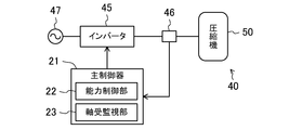
- FIG. 2 is a schematic configuration diagram illustrating a compressor unit of Embodiment 1 and a power supply system to the compressor.
- FIG. 3 is a longitudinal sectional view of the compressor (scroll compressor) of the first embodiment.
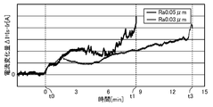
- FIG. 4 is a graph showing the change over time in the amount of current change during the oil removal test, and shows the case where the surface roughness Ra of the journal portion is 0.05 ⁇ m and the case where the surface roughness Ra is 0.03 ⁇ m.
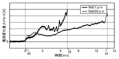
- FIG. 5 is a graph showing the change over time in the amount of current change during the oil removal test, and shows the case where the surface roughness Ra of the journal portion is 0.1 ⁇ m and 0.03 ⁇ m.
- FIG. 6 is a longitudinal sectional view of the compressor (rotary compressor) of the second embodiment.
- Embodiment 1 ⁇ Embodiment 1 will be described.
- the air conditioner (10) of the present embodiment is a refrigeration apparatus including a compressor unit (40) and a refrigerant circuit (30).
- the air conditioner (10) includes an outdoor unit (11) and an indoor unit (13).
- An outdoor circuit (31) is housed in the outdoor unit (11).
- the indoor circuit (35) is housed in the indoor unit (13).
- the outdoor circuit (31) and the indoor circuit (35) are connected to each other via a liquid-side communication pipe (37) and a gas-side communication pipe (38) to form a refrigerant circuit (30).
- the outdoor circuit (31) includes a compressor (50), a four-way switching valve (32), an outdoor heat exchanger (33), and an expansion valve (34).
- the discharge pipe (53) is connected to the first port of the four-way switching valve (32), and the suction pipe (52) is connected to the second port of the four-way switching valve (32).
- the outdoor heat exchanger (33) has a gas-side end connected to the third port of the four-way switching valve (32), and a liquid-side end connected to one end of the expansion valve (34).
- the fourth port of the four-way switching valve (32) is connected to one end of the gas-side communication pipe (38).
- the other end of the expansion valve (34) is connected to one end of a liquid-side communication pipe (37).
- the compressor (50) is a hermetic scroll compressor.
- the compressor (50) forms a compressor unit (40) together with a main controller (21) described later. Details of the compressor (50) will be described later.
- the outdoor heat exchanger (33) is a heat exchanger that exchanges heat of the refrigerant in the refrigerant circuit (30) with outdoor air.
- the expansion valve (34) is a so-called electronic expansion valve.
- the four-way switching valve (32) is a switching valve having four ports.
- the four-way switching valve (32) has a first state (a state shown by a solid line in FIG. 1) in which the first port communicates with the third port and a second port communicates with the fourth port. Is switched to a second state (a state shown by a broken line in FIG. 1) in which the port No. 4 communicates with the fourth port and the second port communicates with the third port.
- the outdoor circuit (31) is provided with a discharge pressure sensor (26) and a suction pressure sensor (27).
- the discharge pressure sensor (26) is connected to a pipe connecting the discharge pipe (53) of the compressor (50) and the first port of the four-way switching valve (32), and controls the pressure of the refrigerant discharged from the compressor (50). Is measured.
- the suction pressure sensor (27) is connected to a pipe connecting the suction pipe of the compressor (50) and the second port of the four-way switching valve (32), and measures the pressure of the refrigerant sucked into the compressor (50). .
- the indoor circuit (35) is provided with an indoor heat exchanger (36).
- the indoor circuit (35) has a liquid side end connected to the other end of the liquid side communication pipe (37), and a gas side end connected to the other end of the gas side communication pipe (38).
- the indoor heat exchanger (36) is a heat exchanger that exchanges heat of the refrigerant in the refrigerant circuit (30) with indoor air.
- the outdoor unit (11) includes an outdoor fan (12) and a main controller (21) in addition to the outdoor circuit (31).
- the outdoor fan (12) is arranged near the outdoor heat exchanger (33), and supplies outdoor air to the outdoor heat exchanger (33).
- the main controller (21) is configured to control devices provided in the outdoor unit (11). The main controller (21) will be described later.
- the outdoor unit (11) is provided with an inverter (45).
- the inverter (45) is configured to convert an AC frequency.
- the input side of the inverter (45) is electrically connected to the commercial power supply (47), and the output side is electrically connected to the compressor (50).
- the output current of the inverter (45) is a drive current for driving the compressor (50).
- a current detector (46) is provided on the wire connecting the inverter (45) and the compressor (50). This current detector measures the effective value of the alternating current (that is, the drive current of the compressor (50)) supplied from the inverter to the compressor (50). The current detector (46) outputs the measured effective value of the drive current to the main controller (21).
- the indoor unit (13) includes an indoor fan (14) and a sub controller (24).
- the indoor fan (14) is arranged near the indoor heat exchanger (36), and supplies indoor air to the indoor heat exchanger (36).
- the sub controller (24) is configured to control equipment provided in the indoor unit (13).
- a remote controller (15) is communicably connected to the sub controller (24).
- the remote control (15) includes a display unit (16) and operation buttons (17) for a user to operate.
- the display unit (16) is a liquid crystal display unit. Information (for example, a set temperature, etc.) indicating the operation state of the air conditioner (10) is displayed on the display unit.
- the air conditioner (10) selectively performs a cooling operation and a heating operation.
- the main controller (21) sets the four-way switching valve (32) to the first state (the state shown by the solid line in FIG. 1), and sets the operating capacity of the compressor (50) and the expansion valve (34). Adjust the opening.
- the refrigerant discharged from the compressor (50) radiates heat to outdoor air in the outdoor heat exchanger (33), condenses, and then expands when passing through the expansion valve (34).
- the refrigerant having passed through the expansion valve (34) flows into the indoor circuit (35) through the liquid-side communication pipe (37), and absorbs heat from indoor air in the indoor heat exchanger (36) to evaporate. Thereafter, the refrigerant flows into the outdoor circuit (31) through the gas-side communication pipe (38), is drawn into the compressor (50), and is compressed.
- the indoor unit (13) blows out the air cooled in the indoor heat exchanger (36) into the indoor space.
- the main controller (21) sets the four-way switching valve (32) to the second state (the state indicated by the broken line in FIG. 1), and sets the operating capacity of the compressor (50) and the expansion valve (34). Adjust the opening.
- the refrigerant discharged from the compressor (50) flows into the indoor circuit (35) through the gas-side communication pipe (38), and releases heat to indoor air in the indoor heat exchanger (36) to condense. Thereafter, the refrigerant flows into the outdoor circuit (31) through the liquid-side communication pipe (37), and expands when passing through the expansion valve (34).
- the refrigerant that has passed through the expansion valve (34) absorbs heat from outdoor air in the outdoor heat exchanger (33), evaporates, and is then sucked into the compressor (50) and compressed.
- the indoor unit (13) blows out the air heated in the indoor heat exchanger (36) into the indoor space.
- the compressor (50) is a hermetic scroll compressor.
- the compressor (50) includes a compression mechanism (60), an electric motor (55), a drive shaft (80), a lower bearing (90), and a casing (51).
- the compression mechanism (60), the electric motor (55), the drive shaft (80), and the lower bearing (90) are housed in a casing (51).
- the casing (51) is a cylindrical closed container whose both ends are closed. The axial direction of the casing (51) is vertical. In the internal space of the casing (51), a compression mechanism (60), an electric motor (55), and a lower bearing (90) are arranged in order from top to bottom.
- the casing (51) includes a suction pipe (52) and a discharge pipe (53).
- the suction pipe (52) passes through the top of the casing (51) and is connected to the compression mechanism (60).
- the discharge pipe (53) penetrates the body of the casing (51) and opens to the internal space of the casing (51).
- the compression mechanism (60) is a scroll-type fluid machine.
- the compression mechanism (60) includes a fixed scroll (70), an orbiting scroll (75), and a housing (65).
- the fixed scroll (70) and the orbiting scroll (75) have their respective wraps meshed with each other to form a plurality of compression chambers (61).
- the housing (65) is fixed to the casing (51), and the fixed scroll (70) is fixed to the housing (65).
- the orbiting scroll (75) includes an orbiting-side end plate (77), an orbiting-side wrap (76), and a boss (78).
- the turning-side end plate portion (77) is formed in a substantially circular flat plate shape.
- the turning-side wrap (76) is formed in a spiral wall shape and protrudes from the front surface (the upper surface in FIG. 3) of the turning-side end plate (77).
- the boss portion (78) is formed in a cylindrical shape protruding from the back surface (the lower surface in FIG. 3) of the turning-side end plate portion (77), and is arranged at the center of the turning-side end plate portion (77).
- An eccentric shaft portion (85) of a drive shaft (80) described later is inserted into the boss portion (78).
- the first bearing metal (79) is fitted into the boss (78).
- the boss (78) is a slide bearing supported by the eccentric shaft (85) of the drive shaft (80).
- the fixed scroll (70) includes a fixed-side end plate (71), a fixed-side wrap (72), and an outer peripheral wall (73).
- the fixed side end plate portion (71) is a relatively thick flat plate portion located above the fixed scroll (70).
- the fixed wrap (72) is formed in a spiral wall shape and protrudes from the front surface (the lower surface in FIG. 3) of the fixed end plate (71).
- the outer peripheral wall portion (73) is formed so as to surround the outer peripheral side of the fixed side wrap (72), and protrudes from the front surface of the fixed side end plate portion (71).
- the housing (65) includes a main body (66) and a main bearing (68).
- the main body (66) is formed in a thick disk shape.
- a crank chamber (67) is formed at the center of the main body (66).
- the crank chamber (67) is a cylindrical depression that opens on the front surface (the upper surface in FIG. 3) of the main body (66).
- the main bearing (68) is formed in a cylindrical shape protruding from the back surface (the lower surface in FIG. 3) of the main body (66), and is arranged at the center of the main body (66).
- the main bearing (68) has a through hole for inserting the drive shaft (80).
- the second bearing metal (69) is fitted into this through hole.
- the main bearing (68) is a sliding bearing that supports the drive shaft (80).
- the electric motor (55) includes a stator (56) and a rotor (57).
- the stator (56) is fixed to the body of the casing (51).
- the rotor (57) is arranged inside the stator (56).
- the drive shaft (80) is inserted through the rotor (57).
- the lower bearing (90) includes one auxiliary bearing portion (91) and three legs (92).
- the sub-bearing (91) is formed in a thick cylindrical shape.
- a third bearing metal (93) is fitted into the sub-bearing (91).
- the auxiliary bearing (91) is a slide bearing that supports the drive shaft (80).
- the leg (92) extends radially from the sub-bearing (91). In the lower bearing (90), the protruding end of each leg (92) is fixed to the body of the casing (51).
- the drive shaft (80) includes a main shaft (81) and an eccentric shaft (85).
- the main shaft section (81) includes a main journal section (82), a sub journal section (83), and an intermediate shaft section (84).
- the drive shaft (80) is arranged such that the eccentric shaft (85) is located above the main shaft (81).
- a main journal portion (82), an intermediate shaft portion (84), and a sub journal portion (83) are arranged in order from one end to the other end.
- the main journal portion (82), the intermediate shaft portion (84), and the sub journal portion (83) are each formed in a columnar shape, and are coaxially arranged.
- the main journal portion (82) has a larger diameter than the intermediate shaft portion (84), and the sub journal portion (83) has a smaller diameter than the intermediate shaft portion (84).
- the main journal portion (82) is located on the upper side, and the sub journal portion (83) is located on the lower side.
- the main journal (82) is inserted through the main bearing (68) of the housing (65).
- the sub journal (83) is inserted through the sub bearing (91) of the lower bearing (90).
- the main journal portion (82) is supported by the main bearing portion (68), and the sub journal portion (83) is supported by the sub bearing portion (91).
- the intermediate shaft part (84) is inserted through the rotor (57) of the electric motor (55).
- the rotor (57) is fixed to the intermediate shaft (84).
- the eccentric shaft (85) is formed in a relatively short shaft, and protrudes from the end face of the main journal (82).
- the drive shaft (80) of the present embodiment has the eccentric shaft (85) located on the upper end side.
- the axis of the eccentric shaft (85) is substantially parallel to the axis of the main shaft (81) and is eccentric with respect to the axis of the main shaft (81).
- the eccentric shaft (85) is inserted into the boss (78) of the orbiting scroll (75).
- the eccentric shaft (85) is a journal that supports the boss (78) of the orbiting scroll (75).
- the drive shaft (80) of the present embodiment has a journal portion in which the main journal portion (82), the sub journal portion (83), and the eccentric shaft portion (85) are supported by the slide bearing. I do.
- the main journal portion (82) and the eccentric shaft portion (85) have a surface roughness Ra of 0.05 ⁇ m or more.
- the surface roughness Ra is an arithmetic average roughness. The reason for setting the surface roughness Ra of the main journal portion (82) and the eccentric shaft portion (85) to 0.05 ⁇ m or more will be described later.
- An oil supply passage (87) is formed in the drive shaft (80).
- the oil supply passage (87) is a passage for supplying the lubricating oil (refrigerating machine oil) stored at the bottom of the casing (51) to the sliding portion. Lubricating oil is supplied to the sliding portions of the drive shaft (80) and each of the main bearing portion (68), the sub bearing portion (91), and the boss portion (78) through an oil supply passage (87).
- each of the main controller (21) and the sub-controller (24) includes a CPU for executing a control program, and a memory for storing the control program, data necessary for executing the control program, and the like.
- the main controller (21) is configured to control devices provided in the outdoor unit (11). For example, the main controller (21) adjusts the rotation speed of the outdoor fan (12) and the opening of the expansion valve (34), and operates the four-way switching valve (32). Further, as shown in FIG. 2, the main controller (21) includes a capacity control unit (22) and a bearing monitoring unit (23). The capacity control unit (22) and the bearing monitoring unit (23) will be described later.
- the sub-controller (24) is configured to control devices provided in the indoor unit (13). For example, the main controller (21) adjusts the rotation speed of the outdoor fan (12) and the opening of the expansion valve (34), and operates the four-way switching valve (32). The sub controller (24) adjusts the rotation speed of the indoor fan (14).
- the capacity control unit (22) is configured to adjust the operating capacity of the compressor (50) so that the air conditioner (10) exhibits an air conditioning capacity corresponding to the air conditioning load of the indoor space.
- the capacity control unit (22) sends a command signal for increasing the output frequency of the inverter (45) to the inverter (45). Output to When the output frequency of the inverter (45) increases, the rotation speed of the compressor (50) increases. As a result, the operating capacity of the compressor (50) increases, and the air conditioning capacity of the air conditioner (10) increases.
- the capacity control unit (22) In the cooling operation, for example, when the measured value of the suction pressure sensor (27) exceeds the low pressure target value of the refrigeration cycle, the capacity control unit (22) increases the air conditioning capacity of the air conditioner (10) in the indoor space. It is determined that the air conditioning load is too small.
- the capacity control unit (22) adjusts the air conditioning capacity of the air conditioner (10) to the indoor state. It is determined that the air conditioning load of the space is too small.
- the capacity control unit (22) sends a command signal for reducing the output frequency of the inverter (45) to the inverter (45). Output to When the output frequency of the inverter (45) decreases, the rotation speed of the compressor (50) decreases. As a result, the operating capacity of the compressor (50) decreases, and the air conditioning capacity of the air conditioner (10) decreases.
- the capacity control unit (22) reduces the air conditioning capacity of the air conditioner (10) to the indoor space. It is determined that the air conditioning load is excessive.
- the capacity control unit (22) increases the air conditioning capacity of the air conditioner (10). It is determined that the air conditioning load of the space is excessive.
- the bearing monitoring unit (23) is configured to detect poor lubrication of the slide bearings (68, 78) based on the measurement value of the current detector (46) (ie, the effective value of the drive current of the compressor). ing. Specifically, the bearing monitoring unit (23) repeatedly performs a determination operation for determining whether an abnormal condition is satisfied or not at every predetermined time (for example, every 30 seconds).
- the abnormal condition is a condition indicating that poor lubrication of the slide bearings (68, 78) has occurred. When the abnormal condition is satisfied, the bearing monitoring unit (23) performs an abnormal operation corresponding to poor lubrication of the sliding bearings (68, 78).
- the abnormal condition is a condition that the generalized current change rate ⁇ Ig exceeds a determination reference value (second reference value).
- the bearing monitoring unit (23) calculates the current change rate RI.
- the current change rate RI is a change amount of a drive current for driving the compressor (50) per unit time (one second in the present embodiment).
- the bearing monitoring unit (23) calculates the amount of change per unit time of the measured value Is of the current detector (46) (that is, the effective value of the drive current of the compressor (50)), and calculates the value as the current change rate.
- the bearing monitoring unit (23) calculates the rated current Ir in the operating state of the compressor (50) at that time.
- the rated current Ir is the drive current of the compressor (50) in the state where the compressor (50) is operating normally (in this embodiment, the effective current of the AC supplied from the inverter (45) to the compressor (50)). Value).
- This rated current Ir varies depending on the operating state of the compressor (50).
- the bearing monitoring unit (23) stores in advance a formula for calculating the rated current Ir from the suction pressure and the discharge pressure of the compressor (50) and the rotation speed of the compressor (50).
- the bearing monitoring unit (23) is obtained by substituting the measured value of the suction pressure sensor (27), the measured value of the discharge pressure sensor (26), and the output frequency of the inverter (45) into this equation. Is the rated current Ir in the operating state of the compressor (50) at that time.
- the bearing monitoring unit (23) stores one predetermined value as the determination reference value H, and compares the calculated generalized current change rate RIg with the determination reference value H.
- the judgment reference value H is a second reference value. Then, when the generalized current change rate RIg exceeds the determination reference value H (RIg> H), the bearing monitoring unit (23) determines that the abnormal condition is satisfied. That is, the bearing monitoring unit (23) of the present embodiment determines that the abnormal condition has been satisfied when the generalized current change rate RIg exceeds the determination reference value H for the first time.
- the abnormal condition of the present embodiment is a condition indicating that the current change rate RI has exceeded the first reference value (H ⁇ Ir in the present embodiment).
- the compressor unit (40) of the present embodiment is configured to perform an abnormal operation corresponding to poor lubrication of the sliding bearings (68, 78) when a predetermined abnormal condition is satisfied.
- the bearing monitoring unit (23) calculates the rated current in the operating state of the compressor (50) at the time of the determination of the abnormal condition, and calculates the value obtained by dividing the current change rate RI by the calculated rated current Ir. (That is, the condition that the generalized current change rate RIg exceeds the determination reference value H) is set as an abnormal condition.
- This abnormal operation is an operation that needs to be performed when lubrication failure of the slide bearings (68, 78) occurs.
- the bearing monitoring unit (23) performs the operation of changing the operating state of the compressor (50) from the normal state to the light load state as an abnormal operation.
- the bearing monitoring unit (23) performs this operation each time an abnormal condition is satisfied.
- the normal state is an operating state of the compressor (50) when the abnormal condition is not satisfied.
- the rotation speed of the compressor (50) has a value set by the capacity control unit (22).
- the light load state is an operation state of the compressor (50) in which the load acting on the slide bearings (68, 78) is smaller than that at the time of determining the abnormal condition.
- the light load state in the present embodiment is an operation state in which the rotation speed of the compressor (50) is lower than that at the time of determining the abnormal condition.
- the bearing monitoring unit (23) performs an operation of lowering the rotational speed of the compressor (50) from that at the time of performing the determination operation (specifically, the output frequency of the inverter (45) is controlled by the capacity control at the time of the determination operation. (Operation of lowering the value set by the unit (22)) is executed as an abnormal operation.
- the bearing monitoring unit (23) measures the duration of the light load state. While the light load state continues, the lubricating oil that has accumulated in the heat exchangers (33, 36) of the refrigerant circuit (30) returns to the compressor (50) together with the refrigerant, and the lubricating oil returns to the sliding bearings (68, 78). In some cases, it becomes possible to secure the amount of refueling.
- the bearing monitoring unit (23) when the duration of the light load state reaches the predetermined reference time, the bearing monitoring unit (23) returns the operating state of the compressor (50) from the light load state to the normal state. In this case, the bearing monitoring unit (23) changes the operating capacity of the compressor (50) (specifically, the output frequency of the inverter (45)) to change the operating state of the compressor (50) to a light load state. Returns to the previous value.
- the bearing monitoring unit (23) of the present embodiment performs an operation of reporting that lubrication failure of the slide bearings (68, 78) has occurred as an abnormal operation.
- the bearing monitoring unit (23) executes this operation when the number of times the abnormal condition is satisfied reaches a predetermined number of times (for example, three times).
- a predetermined number of times for example, three times.
- the bearing monitoring unit (23) displays on the display unit (16) of the remote control (15) a display indicating that lubrication failure of the slide bearings (68, 78) has occurred.
- This display may be, for example, character information such as "an abnormality has occurred in the compressor", or may be an error code corresponding to poor lubrication of the slide bearings (68, 78).
- the surface roughness Ra of the main journal portion (82) and the eccentric shaft portion (85) of the drive shaft is 0.05 ⁇ m or more.
- FIGS. 4 and 5 are graphs showing the change over time in the current change ⁇ I in an oil drainage test for discharging the lubricating oil from the casing (51) during the operation of the compressor (50).
- the drive current of the compressor (50) is adjusted so that the rotation speed of the electric motor (55) is kept constant.
- the thick solid line shows the change over time in the current change ⁇ I when the surface roughness Ra of the main journal portion (82) and the eccentric shaft portion (85) is 0.05 ⁇ m.
- a thick solid line indicates a temporal change of the current change amount ⁇ I when the surface roughness Ra of the main journal portion (82) and the eccentric shaft portion (85) is 0.1 ⁇ m.
- a thin solid line indicates a temporal change of the current change amount ⁇ I when the surface roughness Ra of the main journal portion (82) and the eccentric shaft portion (85) is 0.03 ⁇ m.
- the compression at time t0 is performed both when the surface roughness Ra of the main journal portion (82) and the eccentric shaft portion (85) is 0.05 ⁇ m and 0.1 ⁇ m.
- the current variation ⁇ I gradually increases. The reason is that the oil film formed between the drive shaft (80) and the slide bearings (68, 78) becomes thin, and the friction between the drive shaft (80) and the slide bearings (68, 78) increases.
- the surface roughness Ra of the main journal portion (82) and the eccentric shaft portion (85) is 0.05 ⁇ m or more.
- the phenomenon that occurred in some cases ie, the phenomenon of repeated occurrence and elimination of solid contact between the main journal (82) or the eccentric shaft (85) and the sliding bearings (68, 78) did not occur, and the oil film thickness was reduced. It is presumed that a relatively large area on the surface of the main journal portion (82) or the eccentric shaft portion (85) is seized with the slide bearings (68, 78) when the temperature is reduced to a certain extent.
- the surface roughness Ra of the main journal part (82) and the eccentric shaft part (85) is set to 0.05 ⁇ m or more.
- the surface roughness Ra of the main journal portion (82) and the eccentric shaft portion (85) is desirably 0.4 ⁇ m or less, more desirably 0.3 ⁇ m or less, and desirably 0.2 ⁇ m or less. Is more preferable, and more preferably 0.1 ⁇ m or less.
- the surface roughness Ra of the sub journal part (83) is desirably the same as the surface roughness Ra of the main journal part (82) and the eccentric shaft part (85). However, it does not need to be 0.05 ⁇ m or more.
- the load acting on the sub journal part (83) is smaller than the load acting on the main journal part (82) and the eccentric shaft part (85). Therefore, in the case of poor lubrication, the sub-journal (83) is not usually damaged before the main journal (82) and the eccentric shaft (85). Therefore, if the surface roughness Ra of the main journal portion (82) and the eccentric shaft portion (85) is 0.05 ⁇ m or more, it is assumed that the surface roughness Ra of the sub journal portion (83) is less than 0.05 ⁇ m. In the case of poor lubrication as well, pulsation of the current change amount ⁇ I occurs, and as a result, an abnormal condition is satisfied.
- the compressor unit (40) of the present embodiment includes a compressor (50) and a bearing monitoring unit (23).
- the compressor (50) includes a compression mechanism (60) for sucking and compressing a fluid, an electric motor (55), a drive shaft (80) connected to the electric motor (55) to drive the compression mechanism (60),
- the drive shaft (80) includes a main bearing (68), which is a slide bearing for supporting the journals (82, 85) of the drive shaft (80), and a boss (78).
- the bearing monitoring unit (23) determines that an abnormal condition indicating that the current change rate RI, which is the amount of change per unit time of the drive current for driving the compressor (50), exceeds the first reference value is satisfied.
- At least the surface roughness Ra of the main journal portion (82, 85) and the eccentric shaft portion (85) is 0.05 ⁇ m or more.
- the bearing monitoring unit (23) when a predetermined abnormal condition is satisfied, performs an abnormal operation corresponding to poor lubrication of the sliding bearings (68, 78).
- the abnormal condition is a condition indicating that the current change rate RI related to the drive current of the compressor (50) has exceeded the first reference value.
- the drive current When a pulsation occurs in the drive current, the drive current rapidly changes, so that an abnormal condition is satisfied.
- the main journal portions (82, 85) and the eccentric shaft portion (85) of the drive shaft (80) have a surface roughness Ra of 0.05 ⁇ m or more. For this reason, when the lubrication amount is insufficient for the slide bearings (68, 78) and lubrication failure occurs, pulsation of the drive current occurs. Therefore, according to the present embodiment, it is possible to increase the possibility that the lubrication failure of the slide bearings (68, 78) can be detected by monitoring the current change rate RI of the drive current.
- the bearing monitoring unit (23) of the present embodiment calculates the rated current Ir in the operating state of the compressor (50) at the time of determining the abnormal condition, and divides the current change rate RI by the calculated rated current Ir.
- the condition that the generalized current change rate RIg exceeds the determination reference value H (second reference value) is set as an abnormal condition.
- the rated current Ir is a drive current in a state where the compressor (50) is operating normally.
- the bearing monitoring unit (23) of the present embodiment calculates the rated current Ir in the operating state of the compressor (50) at the time of determining the abnormal condition.
- the current change rate RI exceeds the first reference value. (That is, the abnormal condition is satisfied). Therefore, when the generalized current change rate RIg exceeds the determination reference value H, the bearing monitoring unit (23) of the present embodiment performs an abnormal operation.
- the value of the current change rate RI at which it can be determined that poor lubrication of the slide bearings (68, 78) has occurred depends on the operating state of the compressor (50) at that time. Specifically, the larger the rated current Ir in the operating state of the compressor (50) at that time, the larger the value of the current change rate RI at which it can be determined that poor lubrication of the slide bearings (68, 78) has occurred. For this reason, when it is determined whether or not the lubrication failure of the slide bearings (68, 78) has occurred by comparing the current change rate RI with the first reference value, the operation state of each of the compressors (50) is determined. Needs to be stored in the bearing monitoring unit (23), and the first reference value corresponding to the operating state of the compressor (50) at the time of determination needs to be compared with the current change rate.
- the bearing monitoring unit (23) of the present embodiment stores one type of determination reference value H in advance, and calculates the generalized current change rate RIg regardless of the operating state of the compressor (50). By comparing with one determination reference value H, the success or failure of the abnormal condition can be determined.
- the bearing monitoring unit (23) of the present embodiment changes the operating state of the compressor (50) from the normal state when the abnormal condition is not satisfied, when the load acting on the sliding bearing (68, 78) is abnormal. An operation of changing to a light load state that is smaller than that at the time of the condition determination is performed as an abnormal operation.
- the light load state is an operation state in which the rotational speed of the compressor (50) is lower than that at the time of determining the abnormal condition.
- the bearing monitoring unit (23) of the present embodiment lowers the rotation speed of the compressor (50) than when the abnormal condition is determined.
- the load acting on the main bearing portion (68) and the boss portion (78), which are sliding bearings, is reduced, and the main journal portions (82, 85) and the eccentric shaft portion (85) of the drive shaft (80) are connected to the main shaft.
- the degree of damage to the bearing (68) and the boss (78) can be reduced.
- the bearing monitoring unit (23) of the present embodiment is configured to return the operating state of the compressor (50) to the normal state after setting the operating state to the light load state for a predetermined time. That is, when the abnormal condition is satisfied, the bearing monitoring unit (23) switches the operation state of the compressor (50) from the normal state to the light load state, and changes the operation state of the compressor (50) to the light state for a predetermined time. After maintaining the load state, the operation state of the compressor (50) is returned from the light load state to the normal state.
- the bearing monitoring unit (23) of the present embodiment is configured to perform the operation of reporting that lubrication failure of the slide bearings (68, 78) has occurred as an abnormal operation. Therefore, according to the present embodiment, it is possible to notify the administrator of the air conditioner (10) or the like that an abnormality has occurred in the compressor (50).
- Embodiment 2 ⁇ Embodiment 2 >> Embodiment 2 will be described.
- the air conditioner (10) of the present embodiment is obtained by changing the compressor (50) in the air conditioner (10) of the first embodiment.
- the control system (20) of the air conditioner (10) of the present embodiment performs the same operation as the control system (20) of the first embodiment.
- the compressor (50) of the present embodiment will be described.
- FIG. 6 it is a hermetic rotary compressor.
- the compression mechanism (60), the electric motor (55), and the drive shaft (80) are housed in the casing (51).
- the casing (51) is a cylindrical closed container whose both ends are closed.
- the axial direction of the casing (51) is vertical.
- the electric motor (55) is arranged above the compression mechanism (60).
- the suction pipe (52) penetrates through the body of the casing (51) and is connected to the compression mechanism (60).
- the discharge pipe (53) penetrates through the top of the casing (51) and opens into the internal space of the casing (51).
- the compression mechanism (60) is a so-called swing piston type rotary fluid machine.
- the compression mechanism (60) includes a cylinder (100), a piston (102), a front head (103), and a rear head (104).
- the cylinder (100) is a thick disk-shaped member having a cylinder bore (101) formed in the center.
- a thick cylindrical piston (102) is arranged in the cylinder bore (101).
- An eccentric shaft portion (85) of a drive shaft (80) to be described later is inserted through the piston (102).
- a compression chamber (61) is formed between the wall surface of the cylinder bore (101) and the outer peripheral surface of the piston (102).
- the compression mechanism (60) is provided with a blade that partitions the compression chamber (61) into a high-pressure chamber and a low-pressure chamber.
- the front head (103) is a plate-like member that closes the upper end surface of the cylinder (100).
- a cylindrical main bearing (68) is formed.
- a bearing metal (69) is fitted into the main bearing (68).
- the main bearing (68) having the bearing metal (69) is a slide bearing that supports the drive shaft (80).
- the rear head (104) is a plate-shaped member that closes the lower end surface of the cylinder (100).
- a cylindrical sub-bearing (91) is formed.
- a bearing metal (93) is fitted into the sub bearing portion (91).
- the auxiliary bearing portion (91) having the bearing metal (93) is a slide bearing that supports the drive shaft (80).
- the electric motor (55) includes a stator (56) and a rotor (57).
- the stator (56) is fixed to the body of the casing (51).
- the rotor (57) is arranged inside the stator (56).
- the drive shaft (80) is inserted through the rotor (57).
- the drive shaft (80) includes a main journal (82), a sub journal (83), an eccentric shaft (85), and an upper shaft (86).
- the sub-journal (83), the eccentric shaft (85), the main journal (82), and the upper shaft (86) are arranged in order from the lower end to the upper end. You.
- the main journal part (82), the sub journal part (83), and the upper shaft part (86) are each formed in a columnar shape, and are arranged coaxially with each other.
- the main journal (82) is inserted through the main bearing (68) of the front head (103).
- the sub journal (83) is inserted through the sub bearing (91) of the rear head (104).
- the main journal portion (82) is supported by the main bearing portion (68), and the sub journal portion (83) is supported by the sub bearing portion (91).
- the upper shaft portion (86) is inserted through the rotor (57) of the electric motor (55).
- the rotor (57) is fixed to the upper shaft (86).
- the eccentric shaft portion (85) is formed in a cylindrical shape having a larger diameter than the main journal portion (82) and the sub journal portion (83).
- the axis of the eccentric shaft (85) is substantially parallel to the axes of the main journal (82) and the sub-journal (83), and the axes of the main journal (82) and the sub-journal (83). Eccentric to the heart.
- the eccentric shaft (85) is inserted through the piston (102).
- the eccentric shaft (85) is a journal that supports the piston (102).
- an oil supply passage (87) is formed in the drive shaft (80).
- the oil supply passage (87) is a passage for supplying the lubricating oil (refrigerating machine oil) stored at the bottom of the casing (51) to the sliding portion. Lubricating oil is supplied to the sliding portions of the drive shaft (80) and each of the main bearing portion (68), the sub bearing portion (91), and the piston (102) through an oil supply passage (87).
- the main journal portion (82), the sub journal portion (83), and the eccentric shaft portion (85) constitute a journal portion supported by a slide bearing.
- the main journal portion (82) and the eccentric shaft portion (85) have a surface roughness Ra of 0.05 ⁇ m or more.
- the surface roughness Ra is an arithmetic average roughness. The reason for setting the surface roughness Ra of the main journal portion (82) and the eccentric shaft portion (85) to 0.05 ⁇ m or more is as described in the first embodiment.
- the surface roughness Ra of the main journal portion (82) and the eccentric shaft portion (85) is desirably 0.4 ⁇ m or less, more desirably 0.3 ⁇ m or less.
- the thickness is more preferably 0.2 ⁇ m or less, and further preferably 0.1 ⁇ m or less.
- the surface roughness Ra of the sub journal part (83) is desirably the same as the surface roughness Ra of the main journal part (82) and the eccentric shaft part (85). However, it does not need to be 0.05 ⁇ m or more.
- the load acting on the sub-journal portion (83) is smaller than the load acting on the main journal portion (82) and the eccentric shaft portion (85), as in the first embodiment. . Accordingly, for the same reason as described for the drive shaft (80) of the first embodiment, the surface roughness Ra of the sub journal portion (83) of the drive shaft (80) of the present embodiment needs to be 0.05 ⁇ m or more. There is no.
- the bearing monitoring unit (23) of the main controller (21) performs “an operation for changing the operating state of the compressor (50) from a normal state to a light load state” and “ Or an operation of reporting that lubrication failure of the slide bearings (68, 78) has occurred ”may be performed.
- the bearing monitoring unit (23) of the main controller (21) determines that the abnormal condition is satisfied when the current change rate RI exceeds the first reference value. It may be configured. That is, the bearing monitoring unit (23) may determine whether the abnormal condition is satisfied by comparing the current change rate RI with the first reference value without calculating the generalized current change rate RIg. In this case, the bearing monitoring unit (23) stores in advance a first reference value that differs for each operating state of the compressor (50). Then, the bearing monitoring unit (23) determines a first reference value corresponding to the operating state of the compressor (50) at the time of the determination, and compares the current change rate RI with the determined first reference value to determine whether the abnormality has occurred. Determine whether the condition is satisfied.
- the present disclosure is useful for a refrigeration apparatus.
- Air conditioner (refrigeration equipment) 23 Bearing monitoring unit 40 Compressor unit 50 Compressor 55 Electric motor 60 Compression mechanism 68 Main bearing (sliding bearing) 78 Boss (slide bearing) 80 Drive shaft 82 Main journal part (journal part) 85 Eccentric shaft part (journal part)
Landscapes
- Engineering & Computer Science (AREA)
- General Engineering & Computer Science (AREA)
- Mechanical Engineering (AREA)
- Physics & Mathematics (AREA)
- Thermal Sciences (AREA)
- Computer Hardware Design (AREA)
- Applications Or Details Of Rotary Compressors (AREA)
- Control Of Positive-Displacement Pumps (AREA)
Abstract
L'invention concerne un dispositif frigorifique (10) équipé d'une unité (23) de surveillance de palier. L'unité (23) de surveillance de palier est configurée pour effectuer, si une condition d'anomalie est satisfaite, une opération d'événement anormal correspondant à un défaut de lubrification dans un palier lisse d'un compresseur (50). La condition d'anomalie est une condition indiquant qu'une vitesse de variation de courant, qui est la quantité de variation par unité de temps d'un courant d'excitation (c.à.d. une valeur mesurée à partir d'un capteur de courant) pour entraîner le compresseur (50), a dépassé une première valeur de référence. Par rapport à un arbre d'entraînement du compresseur (50), une partie de coussinet reposant sur le palier lisse présente une rugosité de surface Ra qui n'est pas inférieure à 0,05 μm.
Priority Applications (4)
| Application Number | Priority Date | Filing Date | Title |
|---|---|---|---|
| EP19822074.1A EP3789614B1 (fr) | 2018-06-22 | 2019-06-06 | Dispositif frigorifique |
| ES19822074T ES2938739T3 (es) | 2018-06-22 | 2019-06-06 | Aparato de refrigeración |
| CN201980035417.2A CN112166253B (zh) | 2018-06-22 | 2019-06-06 | 制冷装置 |
| US17/129,240 US11137179B2 (en) | 2018-06-22 | 2020-12-21 | Refrigeration apparatus |
Applications Claiming Priority (2)
| Application Number | Priority Date | Filing Date | Title |
|---|---|---|---|
| JP2018-118566 | 2018-06-22 | ||
| JP2018118566A JP6696533B2 (ja) | 2018-06-22 | 2018-06-22 | 冷凍装置 |
Related Child Applications (1)
| Application Number | Title | Priority Date | Filing Date |
|---|---|---|---|
| US17/129,240 Continuation US11137179B2 (en) | 2018-06-22 | 2020-12-21 | Refrigeration apparatus |
Publications (1)
| Publication Number | Publication Date |
|---|---|
| WO2019244659A1 true WO2019244659A1 (fr) | 2019-12-26 |
Family
ID=68983979
Family Applications (1)
| Application Number | Title | Priority Date | Filing Date |
|---|---|---|---|
| PCT/JP2019/022571 WO2019244659A1 (fr) | 2018-06-22 | 2019-06-06 | Dispositif frigorifique |
Country Status (6)
| Country | Link |
|---|---|
| US (1) | US11137179B2 (fr) |
| EP (1) | EP3789614B1 (fr) |
| JP (1) | JP6696533B2 (fr) |
| CN (1) | CN112166253B (fr) |
| ES (1) | ES2938739T3 (fr) |
| WO (1) | WO2019244659A1 (fr) |
Cited By (1)
| Publication number | Priority date | Publication date | Assignee | Title |
|---|---|---|---|---|
| CN113266961A (zh) * | 2020-02-17 | 2021-08-17 | Lg电子株式会社 | 压缩机及冷却系统 |
Families Citing this family (2)
| Publication number | Priority date | Publication date | Assignee | Title |
|---|---|---|---|---|
| JP2022174864A (ja) * | 2021-05-12 | 2022-11-25 | 三菱重工サーマルシステムズ株式会社 | 電動コンプレッサ制御装置、電動コンプレッサおよび電動コンプレッサ制御方法 |
| CN114320919A (zh) * | 2021-12-31 | 2022-04-12 | 青岛海尔空调电子有限公司 | 一种空调器及其压缩机控制方法 |
Citations (5)
| Publication number | Priority date | Publication date | Assignee | Title |
|---|---|---|---|---|
| JPS63171680U (fr) * | 1987-04-30 | 1988-11-08 | ||
| JP2004060457A (ja) * | 2002-07-25 | 2004-02-26 | Daikin Ind Ltd | 圧縮機内部状態推定装置及び空気調和装置 |
| US20060176186A1 (en) * | 2005-01-24 | 2006-08-10 | Hewlett-Packard Development Company, L.P. | Fan monitoring for failure prediction |
| JP2008261374A (ja) * | 2007-04-10 | 2008-10-30 | Daikin Ind Ltd | 摺動部材およびそれを用いた流体機械 |
| WO2017042949A1 (fr) | 2015-09-11 | 2017-03-16 | ジョンソンコントロールズ ヒタチ エア コンディショニング テクノロジー(ホンコン)リミテッド | Conditionneur d'air comprenant un moyen de pronostic/détection de panne pour compresseur, et procédé de pronostic/détection de panne associé |
Family Cites Families (26)
| Publication number | Priority date | Publication date | Assignee | Title |
|---|---|---|---|---|
| JP2967574B2 (ja) * | 1990-11-16 | 1999-10-25 | 株式会社日立製作所 | 冷凍装置 |
| JP3178287B2 (ja) * | 1994-06-29 | 2001-06-18 | ダイキン工業株式会社 | 圧縮機の油面調整装置 |
| JP3864264B2 (ja) * | 1999-09-30 | 2006-12-27 | 株式会社日立製作所 | 冷凍空調圧縮機 |
| JP4075429B2 (ja) * | 2002-03-26 | 2008-04-16 | 三菱電機株式会社 | 冷凍空調装置 |
| DE10248926B4 (de) * | 2002-10-15 | 2004-11-11 | Bitzer Kühlmaschinenbau Gmbh | Kompressor |
| CN2628217Y (zh) * | 2002-11-21 | 2004-07-28 | 洛阳轴研科技股份有限公司 | 快速消除轴承套圈内表面磨削空程的装置 |
| US8033135B2 (en) * | 2005-09-12 | 2011-10-11 | Panasonic Corporation | Rotary-type fluid machine and refrigeration cycle apparatus |
| US8590325B2 (en) * | 2006-07-19 | 2013-11-26 | Emerson Climate Technologies, Inc. | Protection and diagnostic module for a refrigeration system |
| JP4841579B2 (ja) * | 2008-03-07 | 2011-12-21 | 三菱電機株式会社 | ポンプ及び給湯装置 |
| JP2010084551A (ja) * | 2008-09-30 | 2010-04-15 | Hitachi Appliances Inc | 冷媒圧縮機 |
| WO2012021685A1 (fr) * | 2010-08-13 | 2012-02-16 | Carrier Corporation | Système de sécurité pour le transport réfrigéré |
| CN103492719B (zh) * | 2011-04-25 | 2016-08-17 | 日立空调·家用电器株式会社 | 冷媒压缩机以及使用其的冷冻循环装置 |
| JP6004199B2 (ja) * | 2011-07-01 | 2016-10-05 | パナソニックIpマネジメント株式会社 | 摺動部材 |
| WO2013055816A1 (fr) * | 2011-10-10 | 2013-04-18 | Thermal Dynamics Corporation | Couvercle de frottement amélioré pour une torche à plasma |
| US10309457B2 (en) * | 2012-03-27 | 2019-06-04 | Senju Metal Industry Co., Ltd. | Sliding member |
| EP2917583B1 (fr) * | 2012-10-01 | 2019-05-01 | Thermo King Corporation | Procédés et systèmes permettant de détecter une condition de fonctionnement d'un compresseur |
| DE102013100410A1 (de) * | 2012-10-25 | 2014-05-15 | Institut Für Luft- Und Kältetechnik Gemeinnützige Gmbh | Verfahren und Vorrichtung zum Überwachen einer Kältemittelfüllmenge |
| JP5796620B2 (ja) * | 2013-06-19 | 2015-10-21 | ダイキン工業株式会社 | コンテナ用冷凍装置 |
| US20170097176A1 (en) * | 2014-03-17 | 2017-04-06 | Mitsubishi Electric Corporation | Compressor and refrigeration cycle apparatus |
| JPWO2015140949A1 (ja) * | 2014-03-19 | 2017-04-06 | 三菱電機株式会社 | 密閉形圧縮機及びこの密閉形圧縮機を備えた蒸気圧縮式冷凍サイクル装置 |
| US20160047595A1 (en) * | 2014-08-18 | 2016-02-18 | Paul Mueller Company | Systems and Methods for Operating a Refrigeration System |
| WO2017141388A1 (fr) * | 2016-02-18 | 2017-08-24 | 三菱電機株式会社 | Système frigorifique |
| CN106150999B (zh) * | 2016-07-04 | 2018-02-16 | 珠海格力电器股份有限公司 | 压缩机过载保护检测、控制的方法及装置 |
| US9976933B2 (en) * | 2016-07-08 | 2018-05-22 | Hamilton Sunstrand Corporation | Bearing monitoring system for an air cycle machine and method of monitoring |
| JP6428739B2 (ja) * | 2016-09-30 | 2018-11-28 | 株式会社富士通ゼネラル | 圧縮機 |
| EP3543529B1 (fr) * | 2016-11-18 | 2021-01-20 | Panasonic Intellectual Property Management Co., Ltd. | Compresseur réfrigérant et dispositif de réfrigération comprenant ce dernier |
-
2018
- 2018-06-22 JP JP2018118566A patent/JP6696533B2/ja active Active
-
2019
- 2019-06-06 ES ES19822074T patent/ES2938739T3/es active Active
- 2019-06-06 EP EP19822074.1A patent/EP3789614B1/fr active Active
- 2019-06-06 CN CN201980035417.2A patent/CN112166253B/zh active Active
- 2019-06-06 WO PCT/JP2019/022571 patent/WO2019244659A1/fr unknown
-
2020
- 2020-12-21 US US17/129,240 patent/US11137179B2/en active Active
Patent Citations (5)
| Publication number | Priority date | Publication date | Assignee | Title |
|---|---|---|---|---|
| JPS63171680U (fr) * | 1987-04-30 | 1988-11-08 | ||
| JP2004060457A (ja) * | 2002-07-25 | 2004-02-26 | Daikin Ind Ltd | 圧縮機内部状態推定装置及び空気調和装置 |
| US20060176186A1 (en) * | 2005-01-24 | 2006-08-10 | Hewlett-Packard Development Company, L.P. | Fan monitoring for failure prediction |
| JP2008261374A (ja) * | 2007-04-10 | 2008-10-30 | Daikin Ind Ltd | 摺動部材およびそれを用いた流体機械 |
| WO2017042949A1 (fr) | 2015-09-11 | 2017-03-16 | ジョンソンコントロールズ ヒタチ エア コンディショニング テクノロジー(ホンコン)リミテッド | Conditionneur d'air comprenant un moyen de pronostic/détection de panne pour compresseur, et procédé de pronostic/détection de panne associé |
Non-Patent Citations (1)
| Title |
|---|
| See also references of EP3789614A4 |
Cited By (1)
| Publication number | Priority date | Publication date | Assignee | Title |
|---|---|---|---|---|
| CN113266961A (zh) * | 2020-02-17 | 2021-08-17 | Lg电子株式会社 | 压缩机及冷却系统 |
Also Published As
| Publication number | Publication date |
|---|---|
| EP3789614B1 (fr) | 2022-12-21 |
| JP2019218928A (ja) | 2019-12-26 |
| ES2938739T3 (es) | 2023-04-14 |
| CN112166253B (zh) | 2021-10-26 |
| EP3789614A1 (fr) | 2021-03-10 |
| JP6696533B2 (ja) | 2020-05-20 |
| US20210108836A1 (en) | 2021-04-15 |
| EP3789614A4 (fr) | 2021-04-21 |
| US11137179B2 (en) | 2021-10-05 |
| CN112166253A (zh) | 2021-01-01 |
Similar Documents
| Publication | Publication Date | Title |
|---|---|---|
| US11137179B2 (en) | Refrigeration apparatus | |
| KR101718014B1 (ko) | 오일 레벨 제어수단을 갖는 압축기 | |
| US11280530B2 (en) | Air conditioner provided with means for predicting and detecting failure in compressor and method for predicting and detecting the failure | |
| KR101100004B1 (ko) | 냉각 장치 및 냉각 장치의 냉매 봉입량 설정 방법 | |
| JP2001165073A (ja) | スクロール圧縮機および空気調和機 | |
| US9429158B2 (en) | Air conditioner and compressor having power and saving modes of operation | |
| JP6192806B2 (ja) | 冷凍装置 | |
| KR20040103485A (ko) | 냉각 장치 | |
| KR100468916B1 (ko) | 공기 조화기 및 그 제어 방법 | |
| KR20040103487A (ko) | 냉각 장치 | |
| JP2010038503A (ja) | 冷凍サイクル装置 | |
| JP6003638B2 (ja) | 冷凍装置 | |
| WO2017130321A1 (fr) | Compresseur | |
| WO2018146805A1 (fr) | Dispositif de réfrigération | |
| US20230366400A1 (en) | Gas compressor | |
| CN111981713B (zh) | 制冷设备 | |
| JP2013087975A (ja) | 冷凍装置 | |
| KR102509989B1 (ko) | 압축기 및 그 제어 방법 | |
| JP7216306B2 (ja) | 油濃度検出システム | |
| JP2002147358A (ja) | 気体圧縮機 | |
| JP2006010277A (ja) | 冷蔵庫 | |
| JP2023140969A (ja) | スクリュー圧縮機、スクリュー圧縮機ユニット、および冷凍装置 | |
| JP2009074452A (ja) | 密閉型電動圧縮機 | |
| JP2009097460A (ja) | 回転式電動圧縮機 | |
| KR20180116864A (ko) | 압축기 및 그 제어방법 |
Legal Events
| Date | Code | Title | Description |
|---|---|---|---|
| 121 | Ep: the epo has been informed by wipo that ep was designated in this application |
Ref document number: 19822074 Country of ref document: EP Kind code of ref document: A1 |
|
| ENP | Entry into the national phase |
Ref document number: 2019822074 Country of ref document: EP Effective date: 20201203 |
|
| NENP | Non-entry into the national phase |
Ref country code: DE |