WO2019244659A1 - Refrigeration device - Google Patents
Refrigeration device Download PDFInfo
- Publication number
- WO2019244659A1 WO2019244659A1 PCT/JP2019/022571 JP2019022571W WO2019244659A1 WO 2019244659 A1 WO2019244659 A1 WO 2019244659A1 JP 2019022571 W JP2019022571 W JP 2019022571W WO 2019244659 A1 WO2019244659 A1 WO 2019244659A1
- Authority
- WO
- WIPO (PCT)
- Prior art keywords
- compressor
- bearing
- monitoring unit
- current
- state
- Prior art date
Links
Images


Classifications
-
- F—MECHANICAL ENGINEERING; LIGHTING; HEATING; WEAPONS; BLASTING
- F25—REFRIGERATION OR COOLING; COMBINED HEATING AND REFRIGERATION SYSTEMS; HEAT PUMP SYSTEMS; MANUFACTURE OR STORAGE OF ICE; LIQUEFACTION SOLIDIFICATION OF GASES
- F25B—REFRIGERATION MACHINES, PLANTS OR SYSTEMS; COMBINED HEATING AND REFRIGERATION SYSTEMS; HEAT PUMP SYSTEMS
- F25B31/00—Compressor arrangements
- F25B31/002—Lubrication
-
- F—MECHANICAL ENGINEERING; LIGHTING; HEATING; WEAPONS; BLASTING
- F04—POSITIVE - DISPLACEMENT MACHINES FOR LIQUIDS; PUMPS FOR LIQUIDS OR ELASTIC FLUIDS
- F04B—POSITIVE-DISPLACEMENT MACHINES FOR LIQUIDS; PUMPS
- F04B39/00—Component parts, details, or accessories, of pumps or pumping systems specially adapted for elastic fluids, not otherwise provided for in, or of interest apart from, groups F04B25/00 - F04B37/00
- F04B39/0094—Component parts, details, or accessories, of pumps or pumping systems specially adapted for elastic fluids, not otherwise provided for in, or of interest apart from, groups F04B25/00 - F04B37/00 crankshaft
-
- F—MECHANICAL ENGINEERING; LIGHTING; HEATING; WEAPONS; BLASTING
- F04—POSITIVE - DISPLACEMENT MACHINES FOR LIQUIDS; PUMPS FOR LIQUIDS OR ELASTIC FLUIDS
- F04B—POSITIVE-DISPLACEMENT MACHINES FOR LIQUIDS; PUMPS
- F04B49/00—Control, e.g. of pump delivery, or pump pressure of, or safety measures for, machines, pumps, or pumping installations, not otherwise provided for, or of interest apart from, groups F04B1/00 - F04B47/00
- F04B49/06—Control using electricity
- F04B49/065—Control using electricity and making use of computers
-
- F—MECHANICAL ENGINEERING; LIGHTING; HEATING; WEAPONS; BLASTING
- F04—POSITIVE - DISPLACEMENT MACHINES FOR LIQUIDS; PUMPS FOR LIQUIDS OR ELASTIC FLUIDS
- F04B—POSITIVE-DISPLACEMENT MACHINES FOR LIQUIDS; PUMPS
- F04B49/00—Control, e.g. of pump delivery, or pump pressure of, or safety measures for, machines, pumps, or pumping installations, not otherwise provided for, or of interest apart from, groups F04B1/00 - F04B47/00
- F04B49/10—Other safety measures
-
- F—MECHANICAL ENGINEERING; LIGHTING; HEATING; WEAPONS; BLASTING
- F04—POSITIVE - DISPLACEMENT MACHINES FOR LIQUIDS; PUMPS FOR LIQUIDS OR ELASTIC FLUIDS
- F04C—ROTARY-PISTON, OR OSCILLATING-PISTON, POSITIVE-DISPLACEMENT MACHINES FOR LIQUIDS; ROTARY-PISTON, OR OSCILLATING-PISTON, POSITIVE-DISPLACEMENT PUMPS
- F04C15/00—Component parts, details or accessories of machines, pumps or pumping installations, not provided for in groups F04C2/00 - F04C14/00
- F04C15/0088—Lubrication
- F04C15/0092—Control systems for the circulation of the lubricant
-
- F—MECHANICAL ENGINEERING; LIGHTING; HEATING; WEAPONS; BLASTING
- F04—POSITIVE - DISPLACEMENT MACHINES FOR LIQUIDS; PUMPS FOR LIQUIDS OR ELASTIC FLUIDS
- F04C—ROTARY-PISTON, OR OSCILLATING-PISTON, POSITIVE-DISPLACEMENT MACHINES FOR LIQUIDS; ROTARY-PISTON, OR OSCILLATING-PISTON, POSITIVE-DISPLACEMENT PUMPS
- F04C28/00—Control of, monitoring of, or safety arrangements for, pumps or pumping installations specially adapted for elastic fluids
- F04C28/28—Safety arrangements; Monitoring
-
- F—MECHANICAL ENGINEERING; LIGHTING; HEATING; WEAPONS; BLASTING
- F04—POSITIVE - DISPLACEMENT MACHINES FOR LIQUIDS; PUMPS FOR LIQUIDS OR ELASTIC FLUIDS
- F04C—ROTARY-PISTON, OR OSCILLATING-PISTON, POSITIVE-DISPLACEMENT MACHINES FOR LIQUIDS; ROTARY-PISTON, OR OSCILLATING-PISTON, POSITIVE-DISPLACEMENT PUMPS
- F04C29/00—Component parts, details or accessories of pumps or pumping installations, not provided for in groups F04C18/00 - F04C28/00
- F04C29/02—Lubrication; Lubricant separation
-
- F—MECHANICAL ENGINEERING; LIGHTING; HEATING; WEAPONS; BLASTING
- F16—ENGINEERING ELEMENTS AND UNITS; GENERAL MEASURES FOR PRODUCING AND MAINTAINING EFFECTIVE FUNCTIONING OF MACHINES OR INSTALLATIONS; THERMAL INSULATION IN GENERAL
- F16C—SHAFTS; FLEXIBLE SHAFTS; ELEMENTS OR CRANKSHAFT MECHANISMS; ROTARY BODIES OTHER THAN GEARING ELEMENTS; BEARINGS
- F16C33/00—Parts of bearings; Special methods for making bearings or parts thereof
- F16C33/30—Parts of ball or roller bearings
- F16C33/66—Special parts or details in view of lubrication
- F16C33/6637—Special parts or details in view of lubrication with liquid lubricant
- F16C33/6681—Details of distribution or circulation inside the bearing, e.g. grooves on the cage or passages in the rolling elements
-
- F—MECHANICAL ENGINEERING; LIGHTING; HEATING; WEAPONS; BLASTING
- F04—POSITIVE - DISPLACEMENT MACHINES FOR LIQUIDS; PUMPS FOR LIQUIDS OR ELASTIC FLUIDS
- F04B—POSITIVE-DISPLACEMENT MACHINES FOR LIQUIDS; PUMPS
- F04B2203/00—Motor parameters
- F04B2203/02—Motor parameters of rotating electric motors
- F04B2203/0201—Current
-
- F—MECHANICAL ENGINEERING; LIGHTING; HEATING; WEAPONS; BLASTING
- F04—POSITIVE - DISPLACEMENT MACHINES FOR LIQUIDS; PUMPS FOR LIQUIDS OR ELASTIC FLUIDS
- F04B—POSITIVE-DISPLACEMENT MACHINES FOR LIQUIDS; PUMPS
- F04B49/00—Control, e.g. of pump delivery, or pump pressure of, or safety measures for, machines, pumps, or pumping installations, not otherwise provided for, or of interest apart from, groups F04B1/00 - F04B47/00
- F04B49/06—Control using electricity
-
- F—MECHANICAL ENGINEERING; LIGHTING; HEATING; WEAPONS; BLASTING
- F04—POSITIVE - DISPLACEMENT MACHINES FOR LIQUIDS; PUMPS FOR LIQUIDS OR ELASTIC FLUIDS
- F04C—ROTARY-PISTON, OR OSCILLATING-PISTON, POSITIVE-DISPLACEMENT MACHINES FOR LIQUIDS; ROTARY-PISTON, OR OSCILLATING-PISTON, POSITIVE-DISPLACEMENT PUMPS
- F04C18/00—Rotary-piston pumps specially adapted for elastic fluids
- F04C18/02—Rotary-piston pumps specially adapted for elastic fluids of arcuate-engagement type, i.e. with circular translatory movement of co-operating members, each member having the same number of teeth or tooth-equivalents
- F04C18/0207—Rotary-piston pumps specially adapted for elastic fluids of arcuate-engagement type, i.e. with circular translatory movement of co-operating members, each member having the same number of teeth or tooth-equivalents both members having co-operating elements in spiral form
- F04C18/0215—Rotary-piston pumps specially adapted for elastic fluids of arcuate-engagement type, i.e. with circular translatory movement of co-operating members, each member having the same number of teeth or tooth-equivalents both members having co-operating elements in spiral form where only one member is moving
-
- F—MECHANICAL ENGINEERING; LIGHTING; HEATING; WEAPONS; BLASTING
- F04—POSITIVE - DISPLACEMENT MACHINES FOR LIQUIDS; PUMPS FOR LIQUIDS OR ELASTIC FLUIDS
- F04C—ROTARY-PISTON, OR OSCILLATING-PISTON, POSITIVE-DISPLACEMENT MACHINES FOR LIQUIDS; ROTARY-PISTON, OR OSCILLATING-PISTON, POSITIVE-DISPLACEMENT PUMPS
- F04C18/00—Rotary-piston pumps specially adapted for elastic fluids
- F04C18/30—Rotary-piston pumps specially adapted for elastic fluids having the characteristics covered by two or more of groups F04C18/02, F04C18/08, F04C18/22, F04C18/24, F04C18/48, or having the characteristics covered by one of these groups together with some other type of movement between co-operating members
- F04C18/34—Rotary-piston pumps specially adapted for elastic fluids having the characteristics covered by two or more of groups F04C18/02, F04C18/08, F04C18/22, F04C18/24, F04C18/48, or having the characteristics covered by one of these groups together with some other type of movement between co-operating members having the movement defined in group F04C18/08 or F04C18/22 and relative reciprocation between the co-operating members
- F04C18/356—Rotary-piston pumps specially adapted for elastic fluids having the characteristics covered by two or more of groups F04C18/02, F04C18/08, F04C18/22, F04C18/24, F04C18/48, or having the characteristics covered by one of these groups together with some other type of movement between co-operating members having the movement defined in group F04C18/08 or F04C18/22 and relative reciprocation between the co-operating members with vanes reciprocating with respect to the outer member
-
- F—MECHANICAL ENGINEERING; LIGHTING; HEATING; WEAPONS; BLASTING
- F04—POSITIVE - DISPLACEMENT MACHINES FOR LIQUIDS; PUMPS FOR LIQUIDS OR ELASTIC FLUIDS
- F04C—ROTARY-PISTON, OR OSCILLATING-PISTON, POSITIVE-DISPLACEMENT MACHINES FOR LIQUIDS; ROTARY-PISTON, OR OSCILLATING-PISTON, POSITIVE-DISPLACEMENT PUMPS
- F04C2240/00—Components
- F04C2240/50—Bearings
- F04C2240/54—Hydrostatic or hydrodynamic bearing assemblies specially adapted for rotary positive displacement pumps or compressors
-
- F—MECHANICAL ENGINEERING; LIGHTING; HEATING; WEAPONS; BLASTING
- F04—POSITIVE - DISPLACEMENT MACHINES FOR LIQUIDS; PUMPS FOR LIQUIDS OR ELASTIC FLUIDS
- F04C—ROTARY-PISTON, OR OSCILLATING-PISTON, POSITIVE-DISPLACEMENT MACHINES FOR LIQUIDS; ROTARY-PISTON, OR OSCILLATING-PISTON, POSITIVE-DISPLACEMENT PUMPS
- F04C2270/00—Control; Monitoring or safety arrangements
- F04C2270/80—Diagnostics
-
- F—MECHANICAL ENGINEERING; LIGHTING; HEATING; WEAPONS; BLASTING
- F04—POSITIVE - DISPLACEMENT MACHINES FOR LIQUIDS; PUMPS FOR LIQUIDS OR ELASTIC FLUIDS
- F04C—ROTARY-PISTON, OR OSCILLATING-PISTON, POSITIVE-DISPLACEMENT MACHINES FOR LIQUIDS; ROTARY-PISTON, OR OSCILLATING-PISTON, POSITIVE-DISPLACEMENT PUMPS
- F04C23/00—Combinations of two or more pumps, each being of rotary-piston or oscillating-piston type, specially adapted for elastic fluids; Pumping installations specially adapted for elastic fluids; Multi-stage pumps specially adapted for elastic fluids
- F04C23/008—Hermetic pumps
-
- F—MECHANICAL ENGINEERING; LIGHTING; HEATING; WEAPONS; BLASTING
- F16—ENGINEERING ELEMENTS AND UNITS; GENERAL MEASURES FOR PRODUCING AND MAINTAINING EFFECTIVE FUNCTIONING OF MACHINES OR INSTALLATIONS; THERMAL INSULATION IN GENERAL
- F16C—SHAFTS; FLEXIBLE SHAFTS; ELEMENTS OR CRANKSHAFT MECHANISMS; ROTARY BODIES OTHER THAN GEARING ELEMENTS; BEARINGS
- F16C2233/00—Monitoring condition, e.g. temperature, load, vibration
-
- F—MECHANICAL ENGINEERING; LIGHTING; HEATING; WEAPONS; BLASTING
- F16—ENGINEERING ELEMENTS AND UNITS; GENERAL MEASURES FOR PRODUCING AND MAINTAINING EFFECTIVE FUNCTIONING OF MACHINES OR INSTALLATIONS; THERMAL INSULATION IN GENERAL
- F16C—SHAFTS; FLEXIBLE SHAFTS; ELEMENTS OR CRANKSHAFT MECHANISMS; ROTARY BODIES OTHER THAN GEARING ELEMENTS; BEARINGS
- F16C2360/00—Engines or pumps
Definitions
- the present disclosure relates to a refrigeration apparatus.
- Patent Document 1 discloses an air conditioner provided with compressor failure prediction / detection means. According to this document, when a bearing of a drive shaft (crankshaft) that drives a compression mechanism is damaged due to lack of lubricating oil or the like, a torque for driving the drive shaft fluctuates, and as a result, an electric motor that drives the drive shaft is driven. It is described that a pulsation occurs in the drive current.
- the failure prediction / detection means of this document predicts or detects a compressor failure based on the magnitude and duration of the pulsation of the drive current of the compressor.
- the present inventors have found that even in a situation where the amount of lubrication for the bearing of the drive shaft of the compressor is insufficient, the drive current of the electric motor may be seized without pulsation. I found that.
- the journal of the drive shaft is supported by a slide bearing. If the amount of lubrication to the slide bearing continues to be insufficient, seizure occurs between the journal portion of the drive shaft and the slide bearing. Then, the inventors of the present invention, when the surface roughness of the journal portion is not more than a certain degree, if the lubrication amount to the slide bearing continues to be short, the compressor is required before the journal portion and the slide bearing seize. It was found that the drive current gradually increased with little pulsation.
- An object of the present disclosure is to perform an abnormal operation corresponding to poor lubrication of a slide bearing that supports a drive shaft of a compressor.
- a first aspect of the present disclosure is directed to a refrigeration apparatus (10), and includes a compression mechanism (60) that sucks and compresses a fluid, an electric motor (55), and the compression mechanism that is connected to the electric motor (55).
- a compressor (50) including a drive shaft (80) for driving the drive shaft (60), a slide bearing (68,78) for supporting a journal portion (82,85) of the drive shaft (80);
- the compressor (50) is connected, the refrigerant circuit (30) for circulating the refrigerant to perform a refrigeration cycle, and the current change rate, which is the amount of change per unit time of the drive current for driving the compressor (50),
- a bearing monitoring unit (23) configured to perform an abnormal operation corresponding to poor lubrication of the slide bearings (68, 78) when an abnormal condition indicating that the first reference value has been exceeded is satisfied;
- the journal portion (82, 85) of the drive shaft (80) has a surface roughness Ra of 0.05 ⁇ m or more.
- the bearing monitoring unit (23) when a predetermined abnormal condition is satisfied, performs an abnormal operation corresponding to poor lubrication of the sliding bearings (68, 78).
- the abnormal condition is a condition indicating that the current change rate related to the drive current of the compressor (50) has exceeded the first reference value.
- the drive current When a pulsation occurs in the drive current, the drive current rapidly changes, so that an abnormal condition is satisfied.
- the journal portion (82, 85) of the drive shaft (80) has a surface roughness Ra of 0.05 ⁇ m or more. For this reason, when the lubrication amount is insufficient for the slide bearings (68, 78) and lubrication failure occurs, pulsation of the drive current occurs. Therefore, according to this aspect, by monitoring the current change rate of the drive current, it is possible to increase the possibility of detecting lubrication failure of the slide bearings (68, 78).
- the bearing monitoring unit (23) calculates the rated current in the operating state of the compressor (50) at the time of determining the abnormal condition, and determining a condition that a value obtained by dividing the current change rate by the calculated rated current exceeds a second reference value. It is configured to be an abnormal condition.
- the bearing monitoring unit (23) of the second embodiment calculates the rated current in the operating state of the compressor (50) at the time of determining the abnormal condition.
- the bearing monitoring unit (23) of this embodiment performs an abnormal operation when the value obtained by dividing the current change rate by the calculated rated current exceeds the second reference value.
- the bearing monitoring unit (23) sets an operating state of the compressor (50) to a normal state when the abnormal condition is not satisfied.
- the operation of changing from the state to the light load state in which the load acting on the slide bearings (68, 78) is smaller than that at the time of the determination of the abnormal condition is performed as the abnormal operation.
- the bearing monitoring unit (23) of the third aspect changes the operating state of the compressor (50) from the normal state to the light load state.
- the load acting on the slide bearings (68, 78) becomes smaller than when the abnormal condition is determined. Therefore, according to this aspect, it is possible to reduce the degree of damage to the journal portions (82, 85) and the slide bearings (68, 78) of the drive shaft (80).
- the light load state is an operation state in which the rotational speed of the compressor (50) is lower than that at the time of determining the abnormal condition.
- the bearing monitoring unit (23) lowers the rotation speed of the compressor (50) than when the abnormal condition is determined. Therefore, the load acting on the slide bearings (68, 78) is reduced, and the degree of damage to the journals (82, 85) and the slide bearings (68, 78) of the drive shaft (80) can be reduced. Become.
- the bearing monitoring unit (23) sets the operating state of the compressor (50) to the light load state for a predetermined time. After that, it is configured to return to the normal state.
- the bearing monitoring unit (23) of the fifth embodiment switches the operating state of the compressor (50) from the normal state to the light load state, and changes the operating state of the compressor (50) for a predetermined time.
- the compressor (50) is returned to the normal state from the light load state.
- the bearing monitoring unit (23) performs an operation of notifying that the lubrication failure of the slide bearings (68, 78) has occurred. , The above-mentioned abnormal operation.
- the bearing monitoring unit (23) when the abnormal condition is satisfied, reports that lubrication failure of the slide bearings (68, 78) has occurred. Therefore, according to this aspect, it is possible to notify the administrator of the refrigeration system (10) or the like that an abnormality has occurred in the compressor (50).
- FIG. 1 is a piping diagram illustrating a schematic configuration of the air conditioner of the first embodiment.
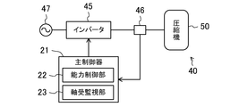
- FIG. 2 is a schematic configuration diagram illustrating a compressor unit of Embodiment 1 and a power supply system to the compressor.
- FIG. 3 is a longitudinal sectional view of the compressor (scroll compressor) of the first embodiment.
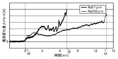
- FIG. 4 is a graph showing the change over time in the amount of current change during the oil removal test, and shows the case where the surface roughness Ra of the journal portion is 0.05 ⁇ m and the case where the surface roughness Ra is 0.03 ⁇ m.
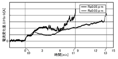
- FIG. 5 is a graph showing the change over time in the amount of current change during the oil removal test, and shows the case where the surface roughness Ra of the journal portion is 0.1 ⁇ m and 0.03 ⁇ m.
- FIG. 6 is a longitudinal sectional view of the compressor (rotary compressor) of the second embodiment.
- Embodiment 1 ⁇ Embodiment 1 will be described.
- the air conditioner (10) of the present embodiment is a refrigeration apparatus including a compressor unit (40) and a refrigerant circuit (30).
- the air conditioner (10) includes an outdoor unit (11) and an indoor unit (13).
- An outdoor circuit (31) is housed in the outdoor unit (11).
- the indoor circuit (35) is housed in the indoor unit (13).
- the outdoor circuit (31) and the indoor circuit (35) are connected to each other via a liquid-side communication pipe (37) and a gas-side communication pipe (38) to form a refrigerant circuit (30).
- the outdoor circuit (31) includes a compressor (50), a four-way switching valve (32), an outdoor heat exchanger (33), and an expansion valve (34).
- the discharge pipe (53) is connected to the first port of the four-way switching valve (32), and the suction pipe (52) is connected to the second port of the four-way switching valve (32).
- the outdoor heat exchanger (33) has a gas-side end connected to the third port of the four-way switching valve (32), and a liquid-side end connected to one end of the expansion valve (34).
- the fourth port of the four-way switching valve (32) is connected to one end of the gas-side communication pipe (38).
- the other end of the expansion valve (34) is connected to one end of a liquid-side communication pipe (37).
- the compressor (50) is a hermetic scroll compressor.
- the compressor (50) forms a compressor unit (40) together with a main controller (21) described later. Details of the compressor (50) will be described later.
- the outdoor heat exchanger (33) is a heat exchanger that exchanges heat of the refrigerant in the refrigerant circuit (30) with outdoor air.
- the expansion valve (34) is a so-called electronic expansion valve.
- the four-way switching valve (32) is a switching valve having four ports.
- the four-way switching valve (32) has a first state (a state shown by a solid line in FIG. 1) in which the first port communicates with the third port and a second port communicates with the fourth port. Is switched to a second state (a state shown by a broken line in FIG. 1) in which the port No. 4 communicates with the fourth port and the second port communicates with the third port.
- the outdoor circuit (31) is provided with a discharge pressure sensor (26) and a suction pressure sensor (27).
- the discharge pressure sensor (26) is connected to a pipe connecting the discharge pipe (53) of the compressor (50) and the first port of the four-way switching valve (32), and controls the pressure of the refrigerant discharged from the compressor (50). Is measured.
- the suction pressure sensor (27) is connected to a pipe connecting the suction pipe of the compressor (50) and the second port of the four-way switching valve (32), and measures the pressure of the refrigerant sucked into the compressor (50). .
- the indoor circuit (35) is provided with an indoor heat exchanger (36).
- the indoor circuit (35) has a liquid side end connected to the other end of the liquid side communication pipe (37), and a gas side end connected to the other end of the gas side communication pipe (38).
- the indoor heat exchanger (36) is a heat exchanger that exchanges heat of the refrigerant in the refrigerant circuit (30) with indoor air.
- the outdoor unit (11) includes an outdoor fan (12) and a main controller (21) in addition to the outdoor circuit (31).
- the outdoor fan (12) is arranged near the outdoor heat exchanger (33), and supplies outdoor air to the outdoor heat exchanger (33).
- the main controller (21) is configured to control devices provided in the outdoor unit (11). The main controller (21) will be described later.
- the outdoor unit (11) is provided with an inverter (45).
- the inverter (45) is configured to convert an AC frequency.
- the input side of the inverter (45) is electrically connected to the commercial power supply (47), and the output side is electrically connected to the compressor (50).
- the output current of the inverter (45) is a drive current for driving the compressor (50).
- a current detector (46) is provided on the wire connecting the inverter (45) and the compressor (50). This current detector measures the effective value of the alternating current (that is, the drive current of the compressor (50)) supplied from the inverter to the compressor (50). The current detector (46) outputs the measured effective value of the drive current to the main controller (21).
- the indoor unit (13) includes an indoor fan (14) and a sub controller (24).
- the indoor fan (14) is arranged near the indoor heat exchanger (36), and supplies indoor air to the indoor heat exchanger (36).
- the sub controller (24) is configured to control equipment provided in the indoor unit (13).
- a remote controller (15) is communicably connected to the sub controller (24).
- the remote control (15) includes a display unit (16) and operation buttons (17) for a user to operate.
- the display unit (16) is a liquid crystal display unit. Information (for example, a set temperature, etc.) indicating the operation state of the air conditioner (10) is displayed on the display unit.
- the air conditioner (10) selectively performs a cooling operation and a heating operation.
- the main controller (21) sets the four-way switching valve (32) to the first state (the state shown by the solid line in FIG. 1), and sets the operating capacity of the compressor (50) and the expansion valve (34). Adjust the opening.
- the refrigerant discharged from the compressor (50) radiates heat to outdoor air in the outdoor heat exchanger (33), condenses, and then expands when passing through the expansion valve (34).
- the refrigerant having passed through the expansion valve (34) flows into the indoor circuit (35) through the liquid-side communication pipe (37), and absorbs heat from indoor air in the indoor heat exchanger (36) to evaporate. Thereafter, the refrigerant flows into the outdoor circuit (31) through the gas-side communication pipe (38), is drawn into the compressor (50), and is compressed.
- the indoor unit (13) blows out the air cooled in the indoor heat exchanger (36) into the indoor space.
- the main controller (21) sets the four-way switching valve (32) to the second state (the state indicated by the broken line in FIG. 1), and sets the operating capacity of the compressor (50) and the expansion valve (34). Adjust the opening.
- the refrigerant discharged from the compressor (50) flows into the indoor circuit (35) through the gas-side communication pipe (38), and releases heat to indoor air in the indoor heat exchanger (36) to condense. Thereafter, the refrigerant flows into the outdoor circuit (31) through the liquid-side communication pipe (37), and expands when passing through the expansion valve (34).
- the refrigerant that has passed through the expansion valve (34) absorbs heat from outdoor air in the outdoor heat exchanger (33), evaporates, and is then sucked into the compressor (50) and compressed.
- the indoor unit (13) blows out the air heated in the indoor heat exchanger (36) into the indoor space.
- the compressor (50) is a hermetic scroll compressor.
- the compressor (50) includes a compression mechanism (60), an electric motor (55), a drive shaft (80), a lower bearing (90), and a casing (51).
- the compression mechanism (60), the electric motor (55), the drive shaft (80), and the lower bearing (90) are housed in a casing (51).
- the casing (51) is a cylindrical closed container whose both ends are closed. The axial direction of the casing (51) is vertical. In the internal space of the casing (51), a compression mechanism (60), an electric motor (55), and a lower bearing (90) are arranged in order from top to bottom.
- the casing (51) includes a suction pipe (52) and a discharge pipe (53).
- the suction pipe (52) passes through the top of the casing (51) and is connected to the compression mechanism (60).
- the discharge pipe (53) penetrates the body of the casing (51) and opens to the internal space of the casing (51).
- the compression mechanism (60) is a scroll-type fluid machine.
- the compression mechanism (60) includes a fixed scroll (70), an orbiting scroll (75), and a housing (65).
- the fixed scroll (70) and the orbiting scroll (75) have their respective wraps meshed with each other to form a plurality of compression chambers (61).
- the housing (65) is fixed to the casing (51), and the fixed scroll (70) is fixed to the housing (65).
- the orbiting scroll (75) includes an orbiting-side end plate (77), an orbiting-side wrap (76), and a boss (78).
- the turning-side end plate portion (77) is formed in a substantially circular flat plate shape.
- the turning-side wrap (76) is formed in a spiral wall shape and protrudes from the front surface (the upper surface in FIG. 3) of the turning-side end plate (77).
- the boss portion (78) is formed in a cylindrical shape protruding from the back surface (the lower surface in FIG. 3) of the turning-side end plate portion (77), and is arranged at the center of the turning-side end plate portion (77).
- An eccentric shaft portion (85) of a drive shaft (80) described later is inserted into the boss portion (78).
- the first bearing metal (79) is fitted into the boss (78).
- the boss (78) is a slide bearing supported by the eccentric shaft (85) of the drive shaft (80).
- the fixed scroll (70) includes a fixed-side end plate (71), a fixed-side wrap (72), and an outer peripheral wall (73).
- the fixed side end plate portion (71) is a relatively thick flat plate portion located above the fixed scroll (70).
- the fixed wrap (72) is formed in a spiral wall shape and protrudes from the front surface (the lower surface in FIG. 3) of the fixed end plate (71).
- the outer peripheral wall portion (73) is formed so as to surround the outer peripheral side of the fixed side wrap (72), and protrudes from the front surface of the fixed side end plate portion (71).
- the housing (65) includes a main body (66) and a main bearing (68).
- the main body (66) is formed in a thick disk shape.
- a crank chamber (67) is formed at the center of the main body (66).
- the crank chamber (67) is a cylindrical depression that opens on the front surface (the upper surface in FIG. 3) of the main body (66).
- the main bearing (68) is formed in a cylindrical shape protruding from the back surface (the lower surface in FIG. 3) of the main body (66), and is arranged at the center of the main body (66).
- the main bearing (68) has a through hole for inserting the drive shaft (80).
- the second bearing metal (69) is fitted into this through hole.
- the main bearing (68) is a sliding bearing that supports the drive shaft (80).
- the electric motor (55) includes a stator (56) and a rotor (57).
- the stator (56) is fixed to the body of the casing (51).
- the rotor (57) is arranged inside the stator (56).
- the drive shaft (80) is inserted through the rotor (57).
- the lower bearing (90) includes one auxiliary bearing portion (91) and three legs (92).
- the sub-bearing (91) is formed in a thick cylindrical shape.
- a third bearing metal (93) is fitted into the sub-bearing (91).
- the auxiliary bearing (91) is a slide bearing that supports the drive shaft (80).
- the leg (92) extends radially from the sub-bearing (91). In the lower bearing (90), the protruding end of each leg (92) is fixed to the body of the casing (51).
- the drive shaft (80) includes a main shaft (81) and an eccentric shaft (85).
- the main shaft section (81) includes a main journal section (82), a sub journal section (83), and an intermediate shaft section (84).
- the drive shaft (80) is arranged such that the eccentric shaft (85) is located above the main shaft (81).
- a main journal portion (82), an intermediate shaft portion (84), and a sub journal portion (83) are arranged in order from one end to the other end.
- the main journal portion (82), the intermediate shaft portion (84), and the sub journal portion (83) are each formed in a columnar shape, and are coaxially arranged.
- the main journal portion (82) has a larger diameter than the intermediate shaft portion (84), and the sub journal portion (83) has a smaller diameter than the intermediate shaft portion (84).
- the main journal portion (82) is located on the upper side, and the sub journal portion (83) is located on the lower side.
- the main journal (82) is inserted through the main bearing (68) of the housing (65).
- the sub journal (83) is inserted through the sub bearing (91) of the lower bearing (90).
- the main journal portion (82) is supported by the main bearing portion (68), and the sub journal portion (83) is supported by the sub bearing portion (91).
- the intermediate shaft part (84) is inserted through the rotor (57) of the electric motor (55).
- the rotor (57) is fixed to the intermediate shaft (84).
- the eccentric shaft (85) is formed in a relatively short shaft, and protrudes from the end face of the main journal (82).
- the drive shaft (80) of the present embodiment has the eccentric shaft (85) located on the upper end side.
- the axis of the eccentric shaft (85) is substantially parallel to the axis of the main shaft (81) and is eccentric with respect to the axis of the main shaft (81).
- the eccentric shaft (85) is inserted into the boss (78) of the orbiting scroll (75).
- the eccentric shaft (85) is a journal that supports the boss (78) of the orbiting scroll (75).
- the drive shaft (80) of the present embodiment has a journal portion in which the main journal portion (82), the sub journal portion (83), and the eccentric shaft portion (85) are supported by the slide bearing. I do.
- the main journal portion (82) and the eccentric shaft portion (85) have a surface roughness Ra of 0.05 ⁇ m or more.
- the surface roughness Ra is an arithmetic average roughness. The reason for setting the surface roughness Ra of the main journal portion (82) and the eccentric shaft portion (85) to 0.05 ⁇ m or more will be described later.
- An oil supply passage (87) is formed in the drive shaft (80).
- the oil supply passage (87) is a passage for supplying the lubricating oil (refrigerating machine oil) stored at the bottom of the casing (51) to the sliding portion. Lubricating oil is supplied to the sliding portions of the drive shaft (80) and each of the main bearing portion (68), the sub bearing portion (91), and the boss portion (78) through an oil supply passage (87).
- each of the main controller (21) and the sub-controller (24) includes a CPU for executing a control program, and a memory for storing the control program, data necessary for executing the control program, and the like.
- the main controller (21) is configured to control devices provided in the outdoor unit (11). For example, the main controller (21) adjusts the rotation speed of the outdoor fan (12) and the opening of the expansion valve (34), and operates the four-way switching valve (32). Further, as shown in FIG. 2, the main controller (21) includes a capacity control unit (22) and a bearing monitoring unit (23). The capacity control unit (22) and the bearing monitoring unit (23) will be described later.
- the sub-controller (24) is configured to control devices provided in the indoor unit (13). For example, the main controller (21) adjusts the rotation speed of the outdoor fan (12) and the opening of the expansion valve (34), and operates the four-way switching valve (32). The sub controller (24) adjusts the rotation speed of the indoor fan (14).
- the capacity control unit (22) is configured to adjust the operating capacity of the compressor (50) so that the air conditioner (10) exhibits an air conditioning capacity corresponding to the air conditioning load of the indoor space.
- the capacity control unit (22) sends a command signal for increasing the output frequency of the inverter (45) to the inverter (45). Output to When the output frequency of the inverter (45) increases, the rotation speed of the compressor (50) increases. As a result, the operating capacity of the compressor (50) increases, and the air conditioning capacity of the air conditioner (10) increases.
- the capacity control unit (22) In the cooling operation, for example, when the measured value of the suction pressure sensor (27) exceeds the low pressure target value of the refrigeration cycle, the capacity control unit (22) increases the air conditioning capacity of the air conditioner (10) in the indoor space. It is determined that the air conditioning load is too small.
- the capacity control unit (22) adjusts the air conditioning capacity of the air conditioner (10) to the indoor state. It is determined that the air conditioning load of the space is too small.
- the capacity control unit (22) sends a command signal for reducing the output frequency of the inverter (45) to the inverter (45). Output to When the output frequency of the inverter (45) decreases, the rotation speed of the compressor (50) decreases. As a result, the operating capacity of the compressor (50) decreases, and the air conditioning capacity of the air conditioner (10) decreases.
- the capacity control unit (22) reduces the air conditioning capacity of the air conditioner (10) to the indoor space. It is determined that the air conditioning load is excessive.
- the capacity control unit (22) increases the air conditioning capacity of the air conditioner (10). It is determined that the air conditioning load of the space is excessive.
- the bearing monitoring unit (23) is configured to detect poor lubrication of the slide bearings (68, 78) based on the measurement value of the current detector (46) (ie, the effective value of the drive current of the compressor). ing. Specifically, the bearing monitoring unit (23) repeatedly performs a determination operation for determining whether an abnormal condition is satisfied or not at every predetermined time (for example, every 30 seconds).
- the abnormal condition is a condition indicating that poor lubrication of the slide bearings (68, 78) has occurred. When the abnormal condition is satisfied, the bearing monitoring unit (23) performs an abnormal operation corresponding to poor lubrication of the sliding bearings (68, 78).
- the abnormal condition is a condition that the generalized current change rate ⁇ Ig exceeds a determination reference value (second reference value).
- the bearing monitoring unit (23) calculates the current change rate RI.
- the current change rate RI is a change amount of a drive current for driving the compressor (50) per unit time (one second in the present embodiment).
- the bearing monitoring unit (23) calculates the amount of change per unit time of the measured value Is of the current detector (46) (that is, the effective value of the drive current of the compressor (50)), and calculates the value as the current change rate.
- the bearing monitoring unit (23) calculates the rated current Ir in the operating state of the compressor (50) at that time.
- the rated current Ir is the drive current of the compressor (50) in the state where the compressor (50) is operating normally (in this embodiment, the effective current of the AC supplied from the inverter (45) to the compressor (50)). Value).
- This rated current Ir varies depending on the operating state of the compressor (50).
- the bearing monitoring unit (23) stores in advance a formula for calculating the rated current Ir from the suction pressure and the discharge pressure of the compressor (50) and the rotation speed of the compressor (50).
- the bearing monitoring unit (23) is obtained by substituting the measured value of the suction pressure sensor (27), the measured value of the discharge pressure sensor (26), and the output frequency of the inverter (45) into this equation. Is the rated current Ir in the operating state of the compressor (50) at that time.
- the bearing monitoring unit (23) stores one predetermined value as the determination reference value H, and compares the calculated generalized current change rate RIg with the determination reference value H.
- the judgment reference value H is a second reference value. Then, when the generalized current change rate RIg exceeds the determination reference value H (RIg> H), the bearing monitoring unit (23) determines that the abnormal condition is satisfied. That is, the bearing monitoring unit (23) of the present embodiment determines that the abnormal condition has been satisfied when the generalized current change rate RIg exceeds the determination reference value H for the first time.
- the abnormal condition of the present embodiment is a condition indicating that the current change rate RI has exceeded the first reference value (H ⁇ Ir in the present embodiment).
- the compressor unit (40) of the present embodiment is configured to perform an abnormal operation corresponding to poor lubrication of the sliding bearings (68, 78) when a predetermined abnormal condition is satisfied.
- the bearing monitoring unit (23) calculates the rated current in the operating state of the compressor (50) at the time of the determination of the abnormal condition, and calculates the value obtained by dividing the current change rate RI by the calculated rated current Ir. (That is, the condition that the generalized current change rate RIg exceeds the determination reference value H) is set as an abnormal condition.
- This abnormal operation is an operation that needs to be performed when lubrication failure of the slide bearings (68, 78) occurs.
- the bearing monitoring unit (23) performs the operation of changing the operating state of the compressor (50) from the normal state to the light load state as an abnormal operation.
- the bearing monitoring unit (23) performs this operation each time an abnormal condition is satisfied.
- the normal state is an operating state of the compressor (50) when the abnormal condition is not satisfied.
- the rotation speed of the compressor (50) has a value set by the capacity control unit (22).
- the light load state is an operation state of the compressor (50) in which the load acting on the slide bearings (68, 78) is smaller than that at the time of determining the abnormal condition.
- the light load state in the present embodiment is an operation state in which the rotation speed of the compressor (50) is lower than that at the time of determining the abnormal condition.
- the bearing monitoring unit (23) performs an operation of lowering the rotational speed of the compressor (50) from that at the time of performing the determination operation (specifically, the output frequency of the inverter (45) is controlled by the capacity control at the time of the determination operation. (Operation of lowering the value set by the unit (22)) is executed as an abnormal operation.
- the bearing monitoring unit (23) measures the duration of the light load state. While the light load state continues, the lubricating oil that has accumulated in the heat exchangers (33, 36) of the refrigerant circuit (30) returns to the compressor (50) together with the refrigerant, and the lubricating oil returns to the sliding bearings (68, 78). In some cases, it becomes possible to secure the amount of refueling.
- the bearing monitoring unit (23) when the duration of the light load state reaches the predetermined reference time, the bearing monitoring unit (23) returns the operating state of the compressor (50) from the light load state to the normal state. In this case, the bearing monitoring unit (23) changes the operating capacity of the compressor (50) (specifically, the output frequency of the inverter (45)) to change the operating state of the compressor (50) to a light load state. Returns to the previous value.
- the bearing monitoring unit (23) of the present embodiment performs an operation of reporting that lubrication failure of the slide bearings (68, 78) has occurred as an abnormal operation.
- the bearing monitoring unit (23) executes this operation when the number of times the abnormal condition is satisfied reaches a predetermined number of times (for example, three times).
- a predetermined number of times for example, three times.
- the bearing monitoring unit (23) displays on the display unit (16) of the remote control (15) a display indicating that lubrication failure of the slide bearings (68, 78) has occurred.
- This display may be, for example, character information such as "an abnormality has occurred in the compressor", or may be an error code corresponding to poor lubrication of the slide bearings (68, 78).
- the surface roughness Ra of the main journal portion (82) and the eccentric shaft portion (85) of the drive shaft is 0.05 ⁇ m or more.
- FIGS. 4 and 5 are graphs showing the change over time in the current change ⁇ I in an oil drainage test for discharging the lubricating oil from the casing (51) during the operation of the compressor (50).
- the drive current of the compressor (50) is adjusted so that the rotation speed of the electric motor (55) is kept constant.
- the thick solid line shows the change over time in the current change ⁇ I when the surface roughness Ra of the main journal portion (82) and the eccentric shaft portion (85) is 0.05 ⁇ m.
- a thick solid line indicates a temporal change of the current change amount ⁇ I when the surface roughness Ra of the main journal portion (82) and the eccentric shaft portion (85) is 0.1 ⁇ m.
- a thin solid line indicates a temporal change of the current change amount ⁇ I when the surface roughness Ra of the main journal portion (82) and the eccentric shaft portion (85) is 0.03 ⁇ m.
- the compression at time t0 is performed both when the surface roughness Ra of the main journal portion (82) and the eccentric shaft portion (85) is 0.05 ⁇ m and 0.1 ⁇ m.
- the current variation ⁇ I gradually increases. The reason is that the oil film formed between the drive shaft (80) and the slide bearings (68, 78) becomes thin, and the friction between the drive shaft (80) and the slide bearings (68, 78) increases.
- the surface roughness Ra of the main journal portion (82) and the eccentric shaft portion (85) is 0.05 ⁇ m or more.
- the phenomenon that occurred in some cases ie, the phenomenon of repeated occurrence and elimination of solid contact between the main journal (82) or the eccentric shaft (85) and the sliding bearings (68, 78) did not occur, and the oil film thickness was reduced. It is presumed that a relatively large area on the surface of the main journal portion (82) or the eccentric shaft portion (85) is seized with the slide bearings (68, 78) when the temperature is reduced to a certain extent.
- the surface roughness Ra of the main journal part (82) and the eccentric shaft part (85) is set to 0.05 ⁇ m or more.
- the surface roughness Ra of the main journal portion (82) and the eccentric shaft portion (85) is desirably 0.4 ⁇ m or less, more desirably 0.3 ⁇ m or less, and desirably 0.2 ⁇ m or less. Is more preferable, and more preferably 0.1 ⁇ m or less.
- the surface roughness Ra of the sub journal part (83) is desirably the same as the surface roughness Ra of the main journal part (82) and the eccentric shaft part (85). However, it does not need to be 0.05 ⁇ m or more.
- the load acting on the sub journal part (83) is smaller than the load acting on the main journal part (82) and the eccentric shaft part (85). Therefore, in the case of poor lubrication, the sub-journal (83) is not usually damaged before the main journal (82) and the eccentric shaft (85). Therefore, if the surface roughness Ra of the main journal portion (82) and the eccentric shaft portion (85) is 0.05 ⁇ m or more, it is assumed that the surface roughness Ra of the sub journal portion (83) is less than 0.05 ⁇ m. In the case of poor lubrication as well, pulsation of the current change amount ⁇ I occurs, and as a result, an abnormal condition is satisfied.
- the compressor unit (40) of the present embodiment includes a compressor (50) and a bearing monitoring unit (23).
- the compressor (50) includes a compression mechanism (60) for sucking and compressing a fluid, an electric motor (55), a drive shaft (80) connected to the electric motor (55) to drive the compression mechanism (60),
- the drive shaft (80) includes a main bearing (68), which is a slide bearing for supporting the journals (82, 85) of the drive shaft (80), and a boss (78).
- the bearing monitoring unit (23) determines that an abnormal condition indicating that the current change rate RI, which is the amount of change per unit time of the drive current for driving the compressor (50), exceeds the first reference value is satisfied.
- At least the surface roughness Ra of the main journal portion (82, 85) and the eccentric shaft portion (85) is 0.05 ⁇ m or more.
- the bearing monitoring unit (23) when a predetermined abnormal condition is satisfied, performs an abnormal operation corresponding to poor lubrication of the sliding bearings (68, 78).
- the abnormal condition is a condition indicating that the current change rate RI related to the drive current of the compressor (50) has exceeded the first reference value.
- the drive current When a pulsation occurs in the drive current, the drive current rapidly changes, so that an abnormal condition is satisfied.
- the main journal portions (82, 85) and the eccentric shaft portion (85) of the drive shaft (80) have a surface roughness Ra of 0.05 ⁇ m or more. For this reason, when the lubrication amount is insufficient for the slide bearings (68, 78) and lubrication failure occurs, pulsation of the drive current occurs. Therefore, according to the present embodiment, it is possible to increase the possibility that the lubrication failure of the slide bearings (68, 78) can be detected by monitoring the current change rate RI of the drive current.
- the bearing monitoring unit (23) of the present embodiment calculates the rated current Ir in the operating state of the compressor (50) at the time of determining the abnormal condition, and divides the current change rate RI by the calculated rated current Ir.
- the condition that the generalized current change rate RIg exceeds the determination reference value H (second reference value) is set as an abnormal condition.
- the rated current Ir is a drive current in a state where the compressor (50) is operating normally.
- the bearing monitoring unit (23) of the present embodiment calculates the rated current Ir in the operating state of the compressor (50) at the time of determining the abnormal condition.
- the current change rate RI exceeds the first reference value. (That is, the abnormal condition is satisfied). Therefore, when the generalized current change rate RIg exceeds the determination reference value H, the bearing monitoring unit (23) of the present embodiment performs an abnormal operation.
- the value of the current change rate RI at which it can be determined that poor lubrication of the slide bearings (68, 78) has occurred depends on the operating state of the compressor (50) at that time. Specifically, the larger the rated current Ir in the operating state of the compressor (50) at that time, the larger the value of the current change rate RI at which it can be determined that poor lubrication of the slide bearings (68, 78) has occurred. For this reason, when it is determined whether or not the lubrication failure of the slide bearings (68, 78) has occurred by comparing the current change rate RI with the first reference value, the operation state of each of the compressors (50) is determined. Needs to be stored in the bearing monitoring unit (23), and the first reference value corresponding to the operating state of the compressor (50) at the time of determination needs to be compared with the current change rate.
- the bearing monitoring unit (23) of the present embodiment stores one type of determination reference value H in advance, and calculates the generalized current change rate RIg regardless of the operating state of the compressor (50). By comparing with one determination reference value H, the success or failure of the abnormal condition can be determined.
- the bearing monitoring unit (23) of the present embodiment changes the operating state of the compressor (50) from the normal state when the abnormal condition is not satisfied, when the load acting on the sliding bearing (68, 78) is abnormal. An operation of changing to a light load state that is smaller than that at the time of the condition determination is performed as an abnormal operation.
- the light load state is an operation state in which the rotational speed of the compressor (50) is lower than that at the time of determining the abnormal condition.
- the bearing monitoring unit (23) of the present embodiment lowers the rotation speed of the compressor (50) than when the abnormal condition is determined.
- the load acting on the main bearing portion (68) and the boss portion (78), which are sliding bearings, is reduced, and the main journal portions (82, 85) and the eccentric shaft portion (85) of the drive shaft (80) are connected to the main shaft.
- the degree of damage to the bearing (68) and the boss (78) can be reduced.
- the bearing monitoring unit (23) of the present embodiment is configured to return the operating state of the compressor (50) to the normal state after setting the operating state to the light load state for a predetermined time. That is, when the abnormal condition is satisfied, the bearing monitoring unit (23) switches the operation state of the compressor (50) from the normal state to the light load state, and changes the operation state of the compressor (50) to the light state for a predetermined time. After maintaining the load state, the operation state of the compressor (50) is returned from the light load state to the normal state.
- the bearing monitoring unit (23) of the present embodiment is configured to perform the operation of reporting that lubrication failure of the slide bearings (68, 78) has occurred as an abnormal operation. Therefore, according to the present embodiment, it is possible to notify the administrator of the air conditioner (10) or the like that an abnormality has occurred in the compressor (50).
- Embodiment 2 ⁇ Embodiment 2 >> Embodiment 2 will be described.
- the air conditioner (10) of the present embodiment is obtained by changing the compressor (50) in the air conditioner (10) of the first embodiment.
- the control system (20) of the air conditioner (10) of the present embodiment performs the same operation as the control system (20) of the first embodiment.
- the compressor (50) of the present embodiment will be described.
- FIG. 6 it is a hermetic rotary compressor.
- the compression mechanism (60), the electric motor (55), and the drive shaft (80) are housed in the casing (51).
- the casing (51) is a cylindrical closed container whose both ends are closed.
- the axial direction of the casing (51) is vertical.
- the electric motor (55) is arranged above the compression mechanism (60).
- the suction pipe (52) penetrates through the body of the casing (51) and is connected to the compression mechanism (60).
- the discharge pipe (53) penetrates through the top of the casing (51) and opens into the internal space of the casing (51).
- the compression mechanism (60) is a so-called swing piston type rotary fluid machine.
- the compression mechanism (60) includes a cylinder (100), a piston (102), a front head (103), and a rear head (104).
- the cylinder (100) is a thick disk-shaped member having a cylinder bore (101) formed in the center.
- a thick cylindrical piston (102) is arranged in the cylinder bore (101).
- An eccentric shaft portion (85) of a drive shaft (80) to be described later is inserted through the piston (102).
- a compression chamber (61) is formed between the wall surface of the cylinder bore (101) and the outer peripheral surface of the piston (102).
- the compression mechanism (60) is provided with a blade that partitions the compression chamber (61) into a high-pressure chamber and a low-pressure chamber.
- the front head (103) is a plate-like member that closes the upper end surface of the cylinder (100).
- a cylindrical main bearing (68) is formed.
- a bearing metal (69) is fitted into the main bearing (68).
- the main bearing (68) having the bearing metal (69) is a slide bearing that supports the drive shaft (80).
- the rear head (104) is a plate-shaped member that closes the lower end surface of the cylinder (100).
- a cylindrical sub-bearing (91) is formed.
- a bearing metal (93) is fitted into the sub bearing portion (91).
- the auxiliary bearing portion (91) having the bearing metal (93) is a slide bearing that supports the drive shaft (80).
- the electric motor (55) includes a stator (56) and a rotor (57).
- the stator (56) is fixed to the body of the casing (51).
- the rotor (57) is arranged inside the stator (56).
- the drive shaft (80) is inserted through the rotor (57).
- the drive shaft (80) includes a main journal (82), a sub journal (83), an eccentric shaft (85), and an upper shaft (86).
- the sub-journal (83), the eccentric shaft (85), the main journal (82), and the upper shaft (86) are arranged in order from the lower end to the upper end. You.
- the main journal part (82), the sub journal part (83), and the upper shaft part (86) are each formed in a columnar shape, and are arranged coaxially with each other.
- the main journal (82) is inserted through the main bearing (68) of the front head (103).
- the sub journal (83) is inserted through the sub bearing (91) of the rear head (104).
- the main journal portion (82) is supported by the main bearing portion (68), and the sub journal portion (83) is supported by the sub bearing portion (91).
- the upper shaft portion (86) is inserted through the rotor (57) of the electric motor (55).
- the rotor (57) is fixed to the upper shaft (86).
- the eccentric shaft portion (85) is formed in a cylindrical shape having a larger diameter than the main journal portion (82) and the sub journal portion (83).
- the axis of the eccentric shaft (85) is substantially parallel to the axes of the main journal (82) and the sub-journal (83), and the axes of the main journal (82) and the sub-journal (83). Eccentric to the heart.
- the eccentric shaft (85) is inserted through the piston (102).
- the eccentric shaft (85) is a journal that supports the piston (102).
- an oil supply passage (87) is formed in the drive shaft (80).
- the oil supply passage (87) is a passage for supplying the lubricating oil (refrigerating machine oil) stored at the bottom of the casing (51) to the sliding portion. Lubricating oil is supplied to the sliding portions of the drive shaft (80) and each of the main bearing portion (68), the sub bearing portion (91), and the piston (102) through an oil supply passage (87).
- the main journal portion (82), the sub journal portion (83), and the eccentric shaft portion (85) constitute a journal portion supported by a slide bearing.
- the main journal portion (82) and the eccentric shaft portion (85) have a surface roughness Ra of 0.05 ⁇ m or more.
- the surface roughness Ra is an arithmetic average roughness. The reason for setting the surface roughness Ra of the main journal portion (82) and the eccentric shaft portion (85) to 0.05 ⁇ m or more is as described in the first embodiment.
- the surface roughness Ra of the main journal portion (82) and the eccentric shaft portion (85) is desirably 0.4 ⁇ m or less, more desirably 0.3 ⁇ m or less.
- the thickness is more preferably 0.2 ⁇ m or less, and further preferably 0.1 ⁇ m or less.
- the surface roughness Ra of the sub journal part (83) is desirably the same as the surface roughness Ra of the main journal part (82) and the eccentric shaft part (85). However, it does not need to be 0.05 ⁇ m or more.
- the load acting on the sub-journal portion (83) is smaller than the load acting on the main journal portion (82) and the eccentric shaft portion (85), as in the first embodiment. . Accordingly, for the same reason as described for the drive shaft (80) of the first embodiment, the surface roughness Ra of the sub journal portion (83) of the drive shaft (80) of the present embodiment needs to be 0.05 ⁇ m or more. There is no.
- the bearing monitoring unit (23) of the main controller (21) performs “an operation for changing the operating state of the compressor (50) from a normal state to a light load state” and “ Or an operation of reporting that lubrication failure of the slide bearings (68, 78) has occurred ”may be performed.
- the bearing monitoring unit (23) of the main controller (21) determines that the abnormal condition is satisfied when the current change rate RI exceeds the first reference value. It may be configured. That is, the bearing monitoring unit (23) may determine whether the abnormal condition is satisfied by comparing the current change rate RI with the first reference value without calculating the generalized current change rate RIg. In this case, the bearing monitoring unit (23) stores in advance a first reference value that differs for each operating state of the compressor (50). Then, the bearing monitoring unit (23) determines a first reference value corresponding to the operating state of the compressor (50) at the time of the determination, and compares the current change rate RI with the determined first reference value to determine whether the abnormality has occurred. Determine whether the condition is satisfied.
- the present disclosure is useful for a refrigeration apparatus.
- Air conditioner (refrigeration equipment) 23 Bearing monitoring unit 40 Compressor unit 50 Compressor 55 Electric motor 60 Compression mechanism 68 Main bearing (sliding bearing) 78 Boss (slide bearing) 80 Drive shaft 82 Main journal part (journal part) 85 Eccentric shaft part (journal part)
Abstract
A refrigeration device (10) is fitted with a bearing monitoring unit (23). The bearing monitoring unit (23) is configured to perform, if an anomaly condition is satisfied, an anomalous-event operation corresponding to a lubrication defect in a sliding bearing of a compressor (50). The anomaly condition is a condition indicating that a current change rate, which is the amount of change per unit time of a drive current (i.e., a measured value from a current sensor ()) for driving the compressor (50), has exceeded a first reference value. With respect to a drive shaft of the compressor (50), a journal portion supported on the sliding bearing has a surface roughness Ra of not less than 0.05 μm.
Description
本開示は、冷凍装置に関するものである。
The present disclosure relates to a refrigeration apparatus.
特許文献1には、圧縮機の故障予知・検知手段を備えた空気調和機が開示されている。この文献には、圧縮機構を駆動する駆動軸(クランク軸)の軸受が潤滑油不足などによって損傷すると、駆動軸を駆動するためのトルクに変動が生じ、その結果、駆動軸を駆動する電動機の駆動電流に脈動が生じることが、記載されている。そして、この文献の故障予知・検知手段は、圧縮機の駆動電流の脈動の大きさと継続時間とに基づいて、圧縮機の故障を予知または検知する。
Patent Document 1 discloses an air conditioner provided with compressor failure prediction / detection means. According to this document, when a bearing of a drive shaft (crankshaft) that drives a compression mechanism is damaged due to lack of lubricating oil or the like, a torque for driving the drive shaft fluctuates, and as a result, an electric motor that drives the drive shaft is driven. It is described that a pulsation occurs in the drive current. The failure prediction / detection means of this document predicts or detects a compressor failure based on the magnitude and duration of the pulsation of the drive current of the compressor.
しかし、本願発明の発明者らは、圧縮機の駆動軸の軸受に対する給油量が不足している状況であっても、電動機の駆動電流に脈動が生じないまま駆動軸の焼き付きに至る場合があることを見出した。
However, the present inventors have found that even in a situation where the amount of lubrication for the bearing of the drive shaft of the compressor is insufficient, the drive current of the electric motor may be seized without pulsation. I found that.
この点について説明する。駆動軸は、そのジャーナル部が滑り軸受に支持される。滑り軸受に対する給油量が不足する状態が続くと、駆動軸のジャーナル部と滑り軸受の焼き付きが生じる。そして、本願発明の発明者らは、ジャーナル部の表面粗さがある程度以下である場合に滑り軸受への給油量不足が続くと、ジャーナル部と滑り軸受の焼き付きに至るまでの間に、圧縮機の駆動電流は殆ど脈動せずに次第に増加することを見出した。
This point will be described. The journal of the drive shaft is supported by a slide bearing. If the amount of lubrication to the slide bearing continues to be insufficient, seizure occurs between the journal portion of the drive shaft and the slide bearing. Then, the inventors of the present invention, when the surface roughness of the journal portion is not more than a certain degree, if the lubrication amount to the slide bearing continues to be short, the compressor is required before the journal portion and the slide bearing seize. It was found that the drive current gradually increased with little pulsation.
このため、圧縮機の駆動電流の脈動の大きさと継続時間とに基づいて圧縮機の故障を予知または検知する従来の技術では、圧縮機の駆動軸を支持する滑り軸受の潤滑不良が生じた場合に、その潤滑不良に対応した異常時動作を実行できないおそれがあった。
For this reason, in the conventional technology of predicting or detecting a compressor failure based on the magnitude and duration of the pulsation of the drive current of the compressor, when the lubrication failure of the sliding bearing that supports the compressor drive shaft occurs. In addition, there is a possibility that the abnormal operation corresponding to the poor lubrication cannot be executed.
本開示の目的は、圧縮機の駆動軸を支持する滑り軸受の潤滑不良に対応した異常時動作を行うことにある。
目的 An object of the present disclosure is to perform an abnormal operation corresponding to poor lubrication of a slide bearing that supports a drive shaft of a compressor.
本開示の第1の態様は、冷凍装置(10)を対象とし、流体を吸入して圧縮する圧縮機構(60)と、電動機(55)と、上記電動機(55)に連結されて上記圧縮機構(60)を駆動する駆動軸(80)と、上記駆動軸(80)のジャーナル部(82,85)を支持する滑り軸受(68,78)とを備えた圧縮機(50)と、上記圧縮機(50)が接続され、冷媒を循環させて冷凍サイクルを行う冷媒回路(30)と、上記圧縮機(50)を駆動するための駆動電流の単位時間当たりの変化量である電流変化率が第1基準値を超えたことを示す異常条件が成立すると、上記滑り軸受(68,78)の潤滑不良に対応した異常時動作を行うように構成された軸受監視部(23)とを備え、上記駆動軸(80)の上記ジャーナル部(82,85)の表面粗さRaが0.05μm以上であることを特徴とする。
A first aspect of the present disclosure is directed to a refrigeration apparatus (10), and includes a compression mechanism (60) that sucks and compresses a fluid, an electric motor (55), and the compression mechanism that is connected to the electric motor (55). A compressor (50) including a drive shaft (80) for driving the drive shaft (60), a slide bearing (68,78) for supporting a journal portion (82,85) of the drive shaft (80); The compressor (50) is connected, the refrigerant circuit (30) for circulating the refrigerant to perform a refrigeration cycle, and the current change rate, which is the amount of change per unit time of the drive current for driving the compressor (50), A bearing monitoring unit (23) configured to perform an abnormal operation corresponding to poor lubrication of the slide bearings (68, 78) when an abnormal condition indicating that the first reference value has been exceeded is satisfied; The journal portion (82, 85) of the drive shaft (80) has a surface roughness Ra of 0.05 μm or more.
第1の態様において、軸受監視部(23)は、所定の異常条件が成立すると、滑り軸受(68,78)の潤滑不良に対応した異常時動作を行う。異常条件は、圧縮機(50)の駆動電流に関する電流変化率が第1基準値を超えたことを示す条件である。駆動電流に脈動が生じると、駆動電流が急激に変化するため、異常条件が成立する。
In the first aspect, when a predetermined abnormal condition is satisfied, the bearing monitoring unit (23) performs an abnormal operation corresponding to poor lubrication of the sliding bearings (68, 78). The abnormal condition is a condition indicating that the current change rate related to the drive current of the compressor (50) has exceeded the first reference value. When a pulsation occurs in the drive current, the drive current rapidly changes, so that an abnormal condition is satisfied.
第1の態様において、駆動軸(80)のジャーナル部(82,85)は、その表面粗さRaが0.05μm以上である。このため、滑り軸受(68,78)に対する給油量が不足して潤滑不良の状態に陥った場合は、駆動電流の脈動が生じる。従って、この態様によれば、駆動電流の電流変化率を監視することによって滑り軸受(68,78)の潤滑不良を検知できる可能性を高めることができる。
In the first aspect, the journal portion (82, 85) of the drive shaft (80) has a surface roughness Ra of 0.05 μm or more. For this reason, when the lubrication amount is insufficient for the slide bearings (68, 78) and lubrication failure occurs, pulsation of the drive current occurs. Therefore, according to this aspect, by monitoring the current change rate of the drive current, it is possible to increase the possibility of detecting lubrication failure of the slide bearings (68, 78).
本開示の第2の態様は、上記第1の態様において、上記圧縮機(50)が正常に作動している状態における上記駆動電流を定格電流としたときに、上記軸受監視部(23)は、上記異常条件の判定時の上記圧縮機(50)の運転状態における上記定格電流を算出し、算出した上記定格電流で上記電流変化率を除した値が第2基準値を超えるという条件を上記異常条件とするように構成されるものである。
According to a second aspect of the present disclosure, in the first aspect, when the drive current in a state where the compressor (50) is operating normally is a rated current, the bearing monitoring unit (23) Calculating the rated current in the operating state of the compressor (50) at the time of determining the abnormal condition, and determining a condition that a value obtained by dividing the current change rate by the calculated rated current exceeds a second reference value. It is configured to be an abnormal condition.
第2の態様の軸受監視部(23)は、異常条件の判定時において、その時の圧縮機(50)の運転状態における定格電流を算出する。軸受監視部(23)が算出した定格電流で電流変化率を除した値が第2基準値を超えると、電流変化率が第1基準値を超えた(即ち、異常条件が成立した)と見なせる。そこで、この態様の軸受監視部(23)は、算出した定格電流で電流変化率を除した値が第2基準値を超えると、異常時動作を行う。
The bearing monitoring unit (23) of the second embodiment calculates the rated current in the operating state of the compressor (50) at the time of determining the abnormal condition. When the value obtained by dividing the current change rate by the rated current calculated by the bearing monitoring unit (23) exceeds the second reference value, it can be considered that the current change rate exceeds the first reference value (that is, the abnormal condition is satisfied). . Therefore, the bearing monitoring unit (23) of this embodiment performs an abnormal operation when the value obtained by dividing the current change rate by the calculated rated current exceeds the second reference value.
本開示の第3の態様は、上記第1又は第2の態様において、上記軸受監視部(23)は、上記圧縮機(50)の運転状態を、上記異常条件が成立していないときの通常状態から、上記滑り軸受(68,78)に作用する荷重が上記異常条件の判定時よりも小さくなる軽負荷状態に変更する動作を、上記異常時動作として行うように構成されるものである。
According to a third aspect of the present disclosure, in the first or second aspect, the bearing monitoring unit (23) sets an operating state of the compressor (50) to a normal state when the abnormal condition is not satisfied. The operation of changing from the state to the light load state in which the load acting on the slide bearings (68, 78) is smaller than that at the time of the determination of the abnormal condition is performed as the abnormal operation.
第3の態様の軸受監視部(23)は、異常条件が成立すると、圧縮機(50)の運転状態を通常状態から軽負荷状態に変更する。圧縮機(50)の運転状態が軽負荷状態になると、滑り軸受(68,78)に作用する荷重が、異常条件の判定時よりも小さくなる。従って、この態様によれば、駆動軸(80)のジャーナル部(82,85)と滑り軸受(68,78)の損傷の程度を小さくすることが可能となる。
軸 受 When the abnormal condition is satisfied, the bearing monitoring unit (23) of the third aspect changes the operating state of the compressor (50) from the normal state to the light load state. When the operation state of the compressor (50) becomes a light load state, the load acting on the slide bearings (68, 78) becomes smaller than when the abnormal condition is determined. Therefore, according to this aspect, it is possible to reduce the degree of damage to the journal portions (82, 85) and the slide bearings (68, 78) of the drive shaft (80).
本開示の第4の態様は、上記第3の態様において、上記軽負荷状態は、上記圧縮機(50)の回転速度が上記異常条件の判定時よりも低い運転状態であるものである。
According to a fourth aspect of the present disclosure, in the third aspect, the light load state is an operation state in which the rotational speed of the compressor (50) is lower than that at the time of determining the abnormal condition.
第4の態様の軸受監視部(23)は、異常条件が成立すると、圧縮機(50)の回転速度を異常条件の判定時よりも低くする。このため、滑り軸受(68,78)に作用する荷重が小さくなり、駆動軸(80)のジャーナル部(82,85)と滑り軸受(68,78)の損傷の程度を小さくすることが可能となる。
(4) When the abnormal condition is satisfied, the bearing monitoring unit (23) according to the fourth embodiment lowers the rotation speed of the compressor (50) than when the abnormal condition is determined. Therefore, the load acting on the slide bearings (68, 78) is reduced, and the degree of damage to the journals (82, 85) and the slide bearings (68, 78) of the drive shaft (80) can be reduced. Become.
本開示の第5の態様は、上記第3又は第4の態様において、上記軸受監視部(23)は、上記圧縮機(50)の運転状態を、所定時間に亘って上記軽負荷状態に設定した後に上記通常状態に戻すように構成されるものである。
According to a fifth aspect of the present disclosure, in the third or fourth aspect, the bearing monitoring unit (23) sets the operating state of the compressor (50) to the light load state for a predetermined time. After that, it is configured to return to the normal state.
第5の態様の軸受監視部(23)は、異常条件が成立すると、圧縮機(50)の運転状態を通常状態から軽負荷状態に切り換え、圧縮機(50)の運転状態を所定時間に亘って軽負荷状態に保ち、その後に圧縮機(50)の運転状態を軽負荷状態から通常状態に戻す。
When the abnormal condition is satisfied, the bearing monitoring unit (23) of the fifth embodiment switches the operating state of the compressor (50) from the normal state to the light load state, and changes the operating state of the compressor (50) for a predetermined time. The compressor (50) is returned to the normal state from the light load state.
本開示の第6の態様は、上記第1又は第2の態様において、上記軸受監視部(23)は、上記滑り軸受(68,78)の潤滑不良が生じていることを発報する動作を、上記異常時動作として行うように構成されるものである。
According to a sixth aspect of the present disclosure, in the first or second aspect, the bearing monitoring unit (23) performs an operation of notifying that the lubrication failure of the slide bearings (68, 78) has occurred. , The above-mentioned abnormal operation.
第6の態様の軸受監視部(23)は、異常条件が成立すると、滑り軸受(68,78)の潤滑不良が生じていることを発報する。従って、この態様によれば、圧縮機(50)に異常が生じていることを、冷凍装置(10)の管理者などに知らせることが可能となる。
The bearing monitoring unit (23) according to the sixth aspect, when the abnormal condition is satisfied, reports that lubrication failure of the slide bearings (68, 78) has occurred. Therefore, according to this aspect, it is possible to notify the administrator of the refrigeration system (10) or the like that an abnormality has occurred in the compressor (50).
《実施形態1》
実施形態1について説明する。本実施形態の空気調和機(10)は、圧縮機ユニット(40)と冷媒回路(30)とを備えた冷凍装置である。 <<Embodiment 1 >>
Embodiment 1 will be described. The air conditioner (10) of the present embodiment is a refrigeration apparatus including a compressor unit (40) and a refrigerant circuit (30).
実施形態1について説明する。本実施形態の空気調和機(10)は、圧縮機ユニット(40)と冷媒回路(30)とを備えた冷凍装置である。 <<
-空気調和機-
〈空気調和機の全体構成〉
図1に示すように、空気調和機(10)は、室外ユニット(11)と室内ユニット(13)とを備える。室外ユニット(11)には、室外回路(31)が収容される。室内ユニット(13)には、室内回路(35)が収容される。室外回路(31)と室内回路(35)は、液側連絡配管(37)及びガス側連絡配管(38)を介して互いに接続されて冷媒回路(30)を構成する。 -Air conditioner-
<Overall configuration of air conditioner>
As shown in FIG. 1, the air conditioner (10) includes an outdoor unit (11) and an indoor unit (13). An outdoor circuit (31) is housed in the outdoor unit (11). The indoor circuit (35) is housed in the indoor unit (13). The outdoor circuit (31) and the indoor circuit (35) are connected to each other via a liquid-side communication pipe (37) and a gas-side communication pipe (38) to form a refrigerant circuit (30).
〈冷媒回路〉
室外回路(31)には、圧縮機(50)と、四方切換弁(32)と、室外熱交換器(33)と、膨張弁(34)とが設けられる。室外回路(31)において、圧縮機(50)は、吐出管(53)が四方切換弁(32)の第1のポートに接続され、吸入管(52)が四方切換弁(32)の第2のポートに接続される。また、室外熱交換器(33)は、ガス側端が四方切換弁(32)の第3のポートに接続され、液側端が膨張弁(34)の一端に接続される。四方切換弁(32)の第4ポートは、ガス側連絡配管(38)の一端に接続される。膨張弁(34)の他端は、液側連絡配管(37)の一端に接続される。 <Refrigerant circuit>
The outdoor circuit (31) includes a compressor (50), a four-way switching valve (32), an outdoor heat exchanger (33), and an expansion valve (34). In the outdoor circuit (31), in the compressor (50), the discharge pipe (53) is connected to the first port of the four-way switching valve (32), and the suction pipe (52) is connected to the second port of the four-way switching valve (32). Connected to the port. The outdoor heat exchanger (33) has a gas-side end connected to the third port of the four-way switching valve (32), and a liquid-side end connected to one end of the expansion valve (34). The fourth port of the four-way switching valve (32) is connected to one end of the gas-side communication pipe (38). The other end of the expansion valve (34) is connected to one end of a liquid-side communication pipe (37).
圧縮機(50)は、全密閉型のスクロール圧縮機である。この圧縮機(50)は、後述する主制御器(21)と共に圧縮機ユニット(40)を構成する。圧縮機(50)の詳細については後述する。室外熱交換器(33)は、冷媒回路(30)の冷媒を室外空気と熱交換させる熱交換器である。膨張弁(34)は、いわゆる電子膨張弁である。四方切換弁(32)は、四つのポートを備えた切換弁である。この四方切換弁(32)は、第1のポートが第3のポートと連通し且つ第2のポートが第4のポートと連通する第1状態(図1に実線で示す状態)と、第1のポートが第4のポートと連通し且つ第2のポートが第3のポートと連通する第2状態(図1に破線で示す状態)とに切り換わるように構成される。
The compressor (50) is a hermetic scroll compressor. The compressor (50) forms a compressor unit (40) together with a main controller (21) described later. Details of the compressor (50) will be described later. The outdoor heat exchanger (33) is a heat exchanger that exchanges heat of the refrigerant in the refrigerant circuit (30) with outdoor air. The expansion valve (34) is a so-called electronic expansion valve. The four-way switching valve (32) is a switching valve having four ports. The four-way switching valve (32) has a first state (a state shown by a solid line in FIG. 1) in which the first port communicates with the third port and a second port communicates with the fourth port. Is switched to a second state (a state shown by a broken line in FIG. 1) in which the port No. 4 communicates with the fourth port and the second port communicates with the third port.
また、室外回路(31)には、吐出圧力センサ(26)と吸入圧力センサ(27)とが設けられる。吐出圧力センサ(26)は、圧縮機(50)の吐出管(53)と四方切換弁(32)の第1のポートを繋ぐ配管に接続され、圧縮機(50)から吐出された冷媒の圧力を計測する。吸入圧力センサ(27)は、圧縮機(50)の吸入管と四方切換弁(32)の第2のポートを繋ぐ配管に接続され、圧縮機(50)へ吸入される冷媒の圧力を計測する。
吐出 The outdoor circuit (31) is provided with a discharge pressure sensor (26) and a suction pressure sensor (27). The discharge pressure sensor (26) is connected to a pipe connecting the discharge pipe (53) of the compressor (50) and the first port of the four-way switching valve (32), and controls the pressure of the refrigerant discharged from the compressor (50). Is measured. The suction pressure sensor (27) is connected to a pipe connecting the suction pipe of the compressor (50) and the second port of the four-way switching valve (32), and measures the pressure of the refrigerant sucked into the compressor (50). .
室内回路(35)には、室内熱交換器(36)が設けられる。室内回路(35)は、液側端が液側連絡配管(37)の他端に接続され、ガス側端がガス側連絡配管(38)の他端に接続される。室内熱交換器(36)は、冷媒回路(30)の冷媒を室内空気と熱交換させる熱交換器である。
室内 The indoor circuit (35) is provided with an indoor heat exchanger (36). The indoor circuit (35) has a liquid side end connected to the other end of the liquid side communication pipe (37), and a gas side end connected to the other end of the gas side communication pipe (38). The indoor heat exchanger (36) is a heat exchanger that exchanges heat of the refrigerant in the refrigerant circuit (30) with indoor air.
〈室外ユニット、インバータ〉
図1に示すように、室外ユニット(11)には、室外回路(31)に加えて、室外ファン(12)と主制御器(21)とが設けられる。室外ファン(12)は、室外熱交換器(33)の近傍に配置され、室外熱交換器(33)へ室外空気を供給する。主制御器(21)は、室外ユニット(11)に設けられた機器を制御するように構成される。主制御器(21)については後述する。 <Outdoor unit, inverter>
As shown in FIG. 1, the outdoor unit (11) includes an outdoor fan (12) and a main controller (21) in addition to the outdoor circuit (31). The outdoor fan (12) is arranged near the outdoor heat exchanger (33), and supplies outdoor air to the outdoor heat exchanger (33). The main controller (21) is configured to control devices provided in the outdoor unit (11). The main controller (21) will be described later.
図2に示すように、室外ユニット(11)には、インバータ(45)が設けられる。インバータ(45)は、交流の周波数を変換するように構成される。インバータ(45)は、入力側が商用電源(47)に電気的に接続され、出力側が圧縮機(50)に電気的に接続される。インバータ(45)の出力電流が、圧縮機(50)を駆動するための駆動電流である。インバータ(45)の出力電流の周波数を変更すると、圧縮機(50)の回転速度が変化し、その結果、圧縮機(50)の運転容量が変化する。
イ ン バ ー タ As shown in FIG. 2, the outdoor unit (11) is provided with an inverter (45). The inverter (45) is configured to convert an AC frequency. The input side of the inverter (45) is electrically connected to the commercial power supply (47), and the output side is electrically connected to the compressor (50). The output current of the inverter (45) is a drive current for driving the compressor (50). When the frequency of the output current of the inverter (45) is changed, the rotation speed of the compressor (50) changes, and as a result, the operating capacity of the compressor (50) changes.
インバータ(45)と圧縮機(50)を接続する電線には、電流検知器(46)が設けられる。この電流検知器は、インバータから圧縮機(50)へ供給される交流(即ち、圧縮機(50)の駆動電流)の実効値を計測する。電流検知器(46)は、計測した駆動電流の実効値を、主制御器(21)に対して出力する。
電流 A current detector (46) is provided on the wire connecting the inverter (45) and the compressor (50). This current detector measures the effective value of the alternating current (that is, the drive current of the compressor (50)) supplied from the inverter to the compressor (50). The current detector (46) outputs the measured effective value of the drive current to the main controller (21).
〈室内ユニット、リモコン〉
図1に示すように、室内ユニット(13)には、室内ファン(14)と副制御器(24)とが設けられる。室内ファン(14)は、室内熱交換器(36)の近傍に配置され、室内熱交換器(36)へ室内空気を供給する。副制御器(24)は、室内ユニット(13)に設けられた機器を制御するように構成される。 <Indoor unit, remote control>
As shown in FIG. 1, the indoor unit (13) includes an indoor fan (14) and a sub controller (24). The indoor fan (14) is arranged near the indoor heat exchanger (36), and supplies indoor air to the indoor heat exchanger (36). The sub controller (24) is configured to control equipment provided in the indoor unit (13).
副制御器(24)には、リモコン(15)が通信可能に接続される。リモコン(15)は、表示部(16)と、ユーザーが操作するための操作ボタン(17)とを備える。表示部(16)は、液晶表示部である。この表示部には、空気調和機(10)の運転状態を示す情報(例えば、設定温度など)が表示される。
リ モ コ ン A remote controller (15) is communicably connected to the sub controller (24). The remote control (15) includes a display unit (16) and operation buttons (17) for a user to operate. The display unit (16) is a liquid crystal display unit. Information (for example, a set temperature, etc.) indicating the operation state of the air conditioner (10) is displayed on the display unit.
〈空気調和機の運転動作〉
空気調和機(10)は、冷房運転と暖房運転を選択的に行う。 <Operation of air conditioner>
The air conditioner (10) selectively performs a cooling operation and a heating operation.
空気調和機(10)は、冷房運転と暖房運転を選択的に行う。 <Operation of air conditioner>
The air conditioner (10) selectively performs a cooling operation and a heating operation.
冷房運転において、主制御器(21)は、四方切換弁(32)を第1状態(図1に実線で示す状態)に設定し、圧縮機(50)の運転容量と膨張弁(34)の開度とを調節する。圧縮機(50)から吐出された冷媒は、室外熱交換器(33)において室外空気へ放熱して凝縮し、その後に膨張弁(34)を通過する際に膨張する。膨張弁(34)を通過した冷媒は、液側連絡配管(37)を通って室内回路(35)へ流入し、室内熱交換器(36)において室内空気から吸熱して蒸発する。その後、冷媒は、ガス側連絡配管(38)を通って室外回路(31)へ流入し、圧縮機(50)へ吸入されて圧縮される。室内ユニット(13)は、室内熱交換器(36)において冷却された空気を室内空間へ吹き出す。
In the cooling operation, the main controller (21) sets the four-way switching valve (32) to the first state (the state shown by the solid line in FIG. 1), and sets the operating capacity of the compressor (50) and the expansion valve (34). Adjust the opening. The refrigerant discharged from the compressor (50) radiates heat to outdoor air in the outdoor heat exchanger (33), condenses, and then expands when passing through the expansion valve (34). The refrigerant having passed through the expansion valve (34) flows into the indoor circuit (35) through the liquid-side communication pipe (37), and absorbs heat from indoor air in the indoor heat exchanger (36) to evaporate. Thereafter, the refrigerant flows into the outdoor circuit (31) through the gas-side communication pipe (38), is drawn into the compressor (50), and is compressed. The indoor unit (13) blows out the air cooled in the indoor heat exchanger (36) into the indoor space.
暖房運転において、主制御器(21)は、四方切換弁(32)を第2状態(図1に破線で示す状態)に設定し、圧縮機(50)の運転容量と膨張弁(34)の開度とを調節する。圧縮機(50)から吐出された冷媒は、ガス側連絡配管(38)を通って室内回路(35)へ流入し、室内熱交換器(36)において室内空気へ放熱して凝縮する。その後、冷媒は、液側連絡配管(37)を通って室外回路(31)へ流入し、膨張弁(34)を通過する際に膨張する。膨張弁(34)を通過した冷媒は、室外熱交換器(33)において室外空気から吸熱して蒸発し、その後に圧縮機(50)へ吸入されて圧縮される。室内ユニット(13)は、室内熱交換器(36)において加熱された空気を室内空間へ吹き出す。
In the heating operation, the main controller (21) sets the four-way switching valve (32) to the second state (the state indicated by the broken line in FIG. 1), and sets the operating capacity of the compressor (50) and the expansion valve (34). Adjust the opening. The refrigerant discharged from the compressor (50) flows into the indoor circuit (35) through the gas-side communication pipe (38), and releases heat to indoor air in the indoor heat exchanger (36) to condense. Thereafter, the refrigerant flows into the outdoor circuit (31) through the liquid-side communication pipe (37), and expands when passing through the expansion valve (34). The refrigerant that has passed through the expansion valve (34) absorbs heat from outdoor air in the outdoor heat exchanger (33), evaporates, and is then sucked into the compressor (50) and compressed. The indoor unit (13) blows out the air heated in the indoor heat exchanger (36) into the indoor space.
-圧縮機-
図3に示すように、圧縮機(50)は、全密閉型のスクロール圧縮機である。この圧縮機(50)は、圧縮機構(60)と、電動機(55)と、駆動軸(80)と、下部軸受(90)と、ケーシング(51)とを備える。圧縮機構(60)と電動機(55)と駆動軸(80)と下部軸受(90)とは、ケーシング(51)に収容される。 -Compressor-
As shown in FIG. 3, the compressor (50) is a hermetic scroll compressor. The compressor (50) includes a compression mechanism (60), an electric motor (55), a drive shaft (80), a lower bearing (90), and a casing (51). The compression mechanism (60), the electric motor (55), the drive shaft (80), and the lower bearing (90) are housed in a casing (51).
〈ケーシング〉
ケーシング(51)は、両端が閉塞された円筒状の密閉容器である。ケーシング(51)は、その軸方向が上下方向となっている。ケーシング(51)の内部空間には、上から下へ向かって順に、圧縮機構(60)と、電動機(55)と、下部軸受(90)とが配置される。ケーシング(51)は、吸入管(52)と吐出管(53)とを備える。吸入管(52)は、ケーシング(51)の頂部を貫通して圧縮機構(60)に接続する。吐出管(53)は、ケーシング(51)の胴部を貫通してケーシング(51)の内部空間に開口する。 <casing>
The casing (51) is a cylindrical closed container whose both ends are closed. The axial direction of the casing (51) is vertical. In the internal space of the casing (51), a compression mechanism (60), an electric motor (55), and a lower bearing (90) are arranged in order from top to bottom. The casing (51) includes a suction pipe (52) and a discharge pipe (53). The suction pipe (52) passes through the top of the casing (51) and is connected to the compression mechanism (60). The discharge pipe (53) penetrates the body of the casing (51) and opens to the internal space of the casing (51).
〈圧縮機構〉
圧縮機構(60)は、スクロール型の流体機械である。この圧縮機構(60)は、固定スクロール(70)と、旋回スクロール(75)と、ハウジング(65)とを備える。固定スクロール(70)と旋回スクロール(75)は、それぞれのラップが互いに噛み合わされて複数の圧縮室(61)を形成する。また、ハウジング(65)はケーシング(51)に固定され、固定スクロール(70)はハウジング(65)に固定される。 <Compression mechanism>
The compression mechanism (60) is a scroll-type fluid machine. The compression mechanism (60) includes a fixed scroll (70), an orbiting scroll (75), and a housing (65). The fixed scroll (70) and the orbiting scroll (75) have their respective wraps meshed with each other to form a plurality of compression chambers (61). The housing (65) is fixed to the casing (51), and the fixed scroll (70) is fixed to the housing (65).
旋回スクロール(75)は、旋回側鏡板部(77)と、旋回側ラップ(76)と、ボス部(78)とを備える。旋回側鏡板部(77)は、概ね円形の平板状に形成される。旋回側ラップ(76)は、渦巻き壁状に形成されて旋回側鏡板部(77)の前面(図3における上面)から突出する。ボス部(78)は、旋回側鏡板部(77)の背面(図3における下面)から突出する円筒状に形成され、旋回側鏡板部(77)の中央部に配置される。このボス部(78)には、後述する駆動軸(80)の偏心軸部(85)が差し込まれる。ボス部(78)には、第1の軸受メタル(79)が嵌め込まれる。このボス部(78)は、駆動軸(80)の偏心軸部(85)に支持される滑り軸受である。
The orbiting scroll (75) includes an orbiting-side end plate (77), an orbiting-side wrap (76), and a boss (78). The turning-side end plate portion (77) is formed in a substantially circular flat plate shape. The turning-side wrap (76) is formed in a spiral wall shape and protrudes from the front surface (the upper surface in FIG. 3) of the turning-side end plate (77). The boss portion (78) is formed in a cylindrical shape protruding from the back surface (the lower surface in FIG. 3) of the turning-side end plate portion (77), and is arranged at the center of the turning-side end plate portion (77). An eccentric shaft portion (85) of a drive shaft (80) described later is inserted into the boss portion (78). The first bearing metal (79) is fitted into the boss (78). The boss (78) is a slide bearing supported by the eccentric shaft (85) of the drive shaft (80).
固定スクロール(70)は、固定側鏡板部(71)と、固定側ラップ(72)と、外周壁部(73)とを備える。固定側鏡板部(71)は、固定スクロール(70)の上部に位置する比較的肉厚の平板状の部分である。固定側ラップ(72)は、渦巻き壁状に形成されて固定側鏡板部(71)の前面(図3における下面)から突出する。外周壁部(73)は、固定側ラップ(72)の外周側を囲むように形成され、固定側鏡板部(71)の前面から突出する。
The fixed scroll (70) includes a fixed-side end plate (71), a fixed-side wrap (72), and an outer peripheral wall (73). The fixed side end plate portion (71) is a relatively thick flat plate portion located above the fixed scroll (70). The fixed wrap (72) is formed in a spiral wall shape and protrudes from the front surface (the lower surface in FIG. 3) of the fixed end plate (71). The outer peripheral wall portion (73) is formed so as to surround the outer peripheral side of the fixed side wrap (72), and protrudes from the front surface of the fixed side end plate portion (71).
ハウジング(65)は、本体部(66)と、主軸受部(68)とを備える。本体部(66)は、肉厚の円板状に形成される。本体部(66)の中央部には、クランク室(67)が形成される。クランク室(67)は、本体部(66)の前面(図3における上面)に開口する円柱状の窪みである。主軸受部(68)は、本体部(66)の背面(図3における下面)から突出する円筒状に形成され、本体部(66)の中央部に配置される。主軸受部(68)には、駆動軸(80)を挿し通すための貫通孔が形成される。この貫通孔には、第2の軸受メタル(69)が嵌め込まれる。この主軸受部(68)は、駆動軸(80)を支持する滑り軸受である。
The housing (65) includes a main body (66) and a main bearing (68). The main body (66) is formed in a thick disk shape. A crank chamber (67) is formed at the center of the main body (66). The crank chamber (67) is a cylindrical depression that opens on the front surface (the upper surface in FIG. 3) of the main body (66). The main bearing (68) is formed in a cylindrical shape protruding from the back surface (the lower surface in FIG. 3) of the main body (66), and is arranged at the center of the main body (66). The main bearing (68) has a through hole for inserting the drive shaft (80). The second bearing metal (69) is fitted into this through hole. The main bearing (68) is a sliding bearing that supports the drive shaft (80).
〈電動機〉
電動機(55)は、固定子(56)と回転子(57)とを備える。固定子(56)は、ケーシング(51)の胴部に固定される。回転子(57)は、固定子(56)の内側に配置される。また、回転子(57)には、駆動軸(80)が挿し通される。 <Electric motor>
The electric motor (55) includes a stator (56) and a rotor (57). The stator (56) is fixed to the body of the casing (51). The rotor (57) is arranged inside the stator (56). The drive shaft (80) is inserted through the rotor (57).
〈下部軸受〉
下部軸受(90)は、一つの副軸受部(91)と、三つの脚部(92)とを備える。副軸受部(91)は、厚肉の円筒状に形成される。副軸受部(91)には、第3の軸受メタル(93)が嵌め込まれる。この副軸受部(91)は、駆動軸(80)を支持する滑り軸受である。脚部(92)は、副軸受部(91)から放射状に延びている。下部軸受(90)は、各脚部(92)の突端がケーシング(51)の胴部に固定される。 <Lower bearing>
The lower bearing (90) includes one auxiliary bearing portion (91) and three legs (92). The sub-bearing (91) is formed in a thick cylindrical shape. A third bearing metal (93) is fitted into the sub-bearing (91). The auxiliary bearing (91) is a slide bearing that supports the drive shaft (80). The leg (92) extends radially from the sub-bearing (91). In the lower bearing (90), the protruding end of each leg (92) is fixed to the body of the casing (51).
〈駆動軸〉
駆動軸(80)は、主軸部(81)と、偏心軸部(85)とを備える。また、主軸部(81)は、主ジャーナル部(82)と、副ジャーナル部(83)と、中間軸部(84)とを備える。駆動軸(80)は、偏心軸部(85)が主軸部(81)の上方に位置する姿勢で配置される。 <Drive shaft>
The drive shaft (80) includes a main shaft (81) and an eccentric shaft (85). The main shaft section (81) includes a main journal section (82), a sub journal section (83), and an intermediate shaft section (84). The drive shaft (80) is arranged such that the eccentric shaft (85) is located above the main shaft (81).
主軸部(81)では、その一端から他端へ向かって順に、主ジャーナル部(82)と、中間軸部(84)と、副ジャーナル部(83)とが配置される。主ジャーナル部(82)と、中間軸部(84)と、副ジャーナル部(83)とは、それぞれが円柱状に形成されて、互いに同軸に配置される。本実施形態の主軸部(81)では、主ジャーナル部(82)が中間軸部(84)よりも大径であり、副ジャーナル部(83)が中間軸部(84)よりも小径である。また、本実施形態の主軸部(81)は、主ジャーナル部(82)が上側に位置し、副ジャーナル部(83)が下側に位置する。
In the main shaft portion (81), a main journal portion (82), an intermediate shaft portion (84), and a sub journal portion (83) are arranged in order from one end to the other end. The main journal portion (82), the intermediate shaft portion (84), and the sub journal portion (83) are each formed in a columnar shape, and are coaxially arranged. In the main shaft portion (81) of the present embodiment, the main journal portion (82) has a larger diameter than the intermediate shaft portion (84), and the sub journal portion (83) has a smaller diameter than the intermediate shaft portion (84). In the main shaft portion (81) of the present embodiment, the main journal portion (82) is located on the upper side, and the sub journal portion (83) is located on the lower side.
主ジャーナル部(82)は、ハウジング(65)の主軸受部(68)に挿し通される。副ジャーナル部(83)は、下部軸受(90)の副軸受部(91)に挿し通される。駆動軸(80)は、主ジャーナル部(82)が主軸受部(68)に支持され、副ジャーナル部(83)が副軸受部(91)に支持される。中間軸部(84)は、電動機(55)の回転子(57)に挿し通される。回転子(57)は、中間軸部(84)に固定される。
The main journal (82) is inserted through the main bearing (68) of the housing (65). The sub journal (83) is inserted through the sub bearing (91) of the lower bearing (90). In the drive shaft (80), the main journal portion (82) is supported by the main bearing portion (68), and the sub journal portion (83) is supported by the sub bearing portion (91). The intermediate shaft part (84) is inserted through the rotor (57) of the electric motor (55). The rotor (57) is fixed to the intermediate shaft (84).
偏心軸部(85)は、比較的短い軸状に形成され、主ジャーナル部(82)の端面から突出する。本実施形態の駆動軸(80)は、偏心軸部(85)が上端側に位置する。偏心軸部(85)の軸心は、主軸部(81)の軸心と実質的に平行であり、主軸部(81)の軸心に対して偏心している。偏心軸部(85)は、旋回スクロール(75)のボス部(78)に差し込まれる。偏心軸部(85)は、旋回スクロール(75)のボス部(78)を支持するジャーナル部である。
The eccentric shaft (85) is formed in a relatively short shaft, and protrudes from the end face of the main journal (82). The drive shaft (80) of the present embodiment has the eccentric shaft (85) located on the upper end side. The axis of the eccentric shaft (85) is substantially parallel to the axis of the main shaft (81) and is eccentric with respect to the axis of the main shaft (81). The eccentric shaft (85) is inserted into the boss (78) of the orbiting scroll (75). The eccentric shaft (85) is a journal that supports the boss (78) of the orbiting scroll (75).
このように、本実施形態の駆動軸(80)は、主ジャーナル部(82)と、副ジャーナル部(83)と、偏心軸部(85)とが、滑り軸受に支持されるジャーナル部を構成する。本実施形態の駆動軸(80)において、主ジャーナル部(82)と偏心軸部(85)とは、それぞれの表面粗さRaが0.05μm以上である。表面粗さRaは、算術平均粗さである。主ジャーナル部(82)及び偏心軸部(85)の表面粗さRaを0.05μm以上にする理由は、後述する。
As described above, the drive shaft (80) of the present embodiment has a journal portion in which the main journal portion (82), the sub journal portion (83), and the eccentric shaft portion (85) are supported by the slide bearing. I do. In the drive shaft (80) of the present embodiment, the main journal portion (82) and the eccentric shaft portion (85) have a surface roughness Ra of 0.05 μm or more. The surface roughness Ra is an arithmetic average roughness. The reason for setting the surface roughness Ra of the main journal portion (82) and the eccentric shaft portion (85) to 0.05 μm or more will be described later.
駆動軸(80)には、給油通路(87)が形成される。給油通路(87)は、ケーシング(51)の底部に貯留された潤滑油(冷凍機油)を摺動箇所へ供給するための通路である。主軸受部(68)、副軸受部(91)、及びボス部(78)のそれぞれと駆動軸(80)の摺動箇所には、給油通路(87)を通じて潤滑油が供給される。
油 An oil supply passage (87) is formed in the drive shaft (80). The oil supply passage (87) is a passage for supplying the lubricating oil (refrigerating machine oil) stored at the bottom of the casing (51) to the sliding portion. Lubricating oil is supplied to the sliding portions of the drive shaft (80) and each of the main bearing portion (68), the sub bearing portion (91), and the boss portion (78) through an oil supply passage (87).
-制御システム-
本実施形態の空気調和機(10)では、室外ユニット(11)の主制御器(21)と、室内ユニット(13)の副制御器(24)とが、互いに配線によって接続されて制御システム(20)を構成する。 -Control system-
In the air conditioner (10) of the present embodiment, the main controller (21) of the outdoor unit (11) and the sub-controller (24) of the indoor unit (13) are connected to each other by wiring to form a control system ( Construct 20).
図示しないが、主制御器(21)と副制御器(24)のそれぞれは、制御プログラムを実行するCPUと、制御プログラムやそれを実行するのに必要なデータ等を記憶するメモリとを備える。
Although not shown, each of the main controller (21) and the sub-controller (24) includes a CPU for executing a control program, and a memory for storing the control program, data necessary for executing the control program, and the like.
上述したように、主制御器(21)は、室外ユニット(11)に設けられた機器を制御するように構成される。例えば、主制御器(21)は、室外ファン(12)の回転速度と、膨張弁(34)の開度とを調節すると共に、四方切換弁(32)を操作する。また、図2に示すように、主制御器(21)は、能力制御部(22)と、軸受監視部(23)とを備える。能力制御部(22)及び軸受監視部(23)については、後述する。
主 As described above, the main controller (21) is configured to control devices provided in the outdoor unit (11). For example, the main controller (21) adjusts the rotation speed of the outdoor fan (12) and the opening of the expansion valve (34), and operates the four-way switching valve (32). Further, as shown in FIG. 2, the main controller (21) includes a capacity control unit (22) and a bearing monitoring unit (23). The capacity control unit (22) and the bearing monitoring unit (23) will be described later.
上述したように、副制御器(24)は、室内ユニット(13)に設けられた機器を制御するように構成される。例えば、主制御器(21)は、室外ファン(12)の回転速度と、膨張弁(34)の開度とを調節すると共に、四方切換弁(32)を操作する。また、副制御器(24)は、室内ファン(14)の回転速度を調節する。
副 As described above, the sub-controller (24) is configured to control devices provided in the indoor unit (13). For example, the main controller (21) adjusts the rotation speed of the outdoor fan (12) and the opening of the expansion valve (34), and operates the four-way switching valve (32). The sub controller (24) adjusts the rotation speed of the indoor fan (14).
-能力制御部-
能力制御部(22)は、空気調和機(10)が室内空間の空調負荷に見合った空調能力を発揮するように、圧縮機(50)の運転容量を調節するように構成される。 -Capability control unit-
The capacity control unit (22) is configured to adjust the operating capacity of the compressor (50) so that the air conditioner (10) exhibits an air conditioning capacity corresponding to the air conditioning load of the indoor space.
空気調和機(10)の空調能力が室内空間の空調負荷に対して過少である場合、能力制御部(22)は、インバータ(45)の出力周波数を引き上げるための指令信号を、インバータ(45)に対して出力する。インバータ(45)の出力周波数が上昇すると、圧縮機(50)の回転速度が上昇する。その結果、圧縮機(50)の運転容量が増加し、空気調和機(10)の空調能力が増加する。
If the air conditioning capacity of the air conditioner (10) is too small for the air conditioning load in the indoor space, the capacity control unit (22) sends a command signal for increasing the output frequency of the inverter (45) to the inverter (45). Output to When the output frequency of the inverter (45) increases, the rotation speed of the compressor (50) increases. As a result, the operating capacity of the compressor (50) increases, and the air conditioning capacity of the air conditioner (10) increases.
冷房運転において、能力制御部(22)は、例えば吸入圧力センサ(27)の計測値が冷凍サイクルの低圧の目標値を上回っている場合に、空気調和機(10)の空調能力が室内空間の空調負荷に対して過少であると判断する。一方、暖房運転において、能力制御部(22)は、例えば吐出圧力センサ(26)の計測値が冷凍サイクルの高圧の目標値を下回っている場合に、空気調和機(10)の空調能力が室内空間の空調負荷に対して過少であると判断する。
In the cooling operation, for example, when the measured value of the suction pressure sensor (27) exceeds the low pressure target value of the refrigeration cycle, the capacity control unit (22) increases the air conditioning capacity of the air conditioner (10) in the indoor space. It is determined that the air conditioning load is too small. On the other hand, in the heating operation, for example, when the measured value of the discharge pressure sensor (26) is lower than the high pressure target value of the refrigeration cycle, the capacity control unit (22) adjusts the air conditioning capacity of the air conditioner (10) to the indoor state. It is determined that the air conditioning load of the space is too small.
空気調和機(10)の空調能力が室内空間の空調負荷に対して過多である場合、能力制御部(22)は、インバータ(45)の出力周波数を引き下げるための指令信号を、インバータ(45)に対して出力する。インバータ(45)の出力周波数が低下すると、圧縮機(50)の回転速度が低下する。その結果、圧縮機(50)の運転容量が減少し、空気調和機(10)の空調能力が減少する。
If the air conditioning capacity of the air conditioner (10) is excessive with respect to the air conditioning load in the indoor space, the capacity control unit (22) sends a command signal for reducing the output frequency of the inverter (45) to the inverter (45). Output to When the output frequency of the inverter (45) decreases, the rotation speed of the compressor (50) decreases. As a result, the operating capacity of the compressor (50) decreases, and the air conditioning capacity of the air conditioner (10) decreases.
冷房運転において、能力制御部(22)は、例えば吸入圧力センサ(27)の計測値が冷凍サイクルの低圧の目標値を下回っている場合に、空気調和機(10)の空調能力が室内空間の空調負荷に対して過多であると判断する。一方、暖房運転において、能力制御部(22)は、例えば吐出圧力センサ(26)の計測値が冷凍サイクルの高圧の目標値を上回っている場合に、空気調和機(10)の空調能力が室内空間の空調負荷に対して過多であると判断する。
In the cooling operation, for example, when the measured value of the suction pressure sensor (27) is lower than the low pressure target value of the refrigeration cycle, the capacity control unit (22) reduces the air conditioning capacity of the air conditioner (10) to the indoor space. It is determined that the air conditioning load is excessive. On the other hand, in the heating operation, for example, when the measured value of the discharge pressure sensor (26) exceeds the high pressure target value of the refrigeration cycle, the capacity control unit (22) increases the air conditioning capacity of the air conditioner (10). It is determined that the air conditioning load of the space is excessive.
-軸受監視部-
軸受監視部(23)は、電流検知器(46)の計測値(即ち、圧縮機の駆動電流の実効値)に基づいて、滑り軸受(68,78)の潤滑不良を検知するように構成されている。具体的に、軸受監視部(23)は、異常条件の成否を判定する判定動作を、所定時間毎(例えば、30秒毎)に繰り返し行う。異常条件は、滑り軸受(68,78)の潤滑不良が生じていることを示す条件である。また、軸受監視部(23)は、異常条件が成立すると、滑り軸受(68,78)の潤滑不良に対応した異常時動作を行う。 -Bearing monitoring section-
The bearing monitoring unit (23) is configured to detect poor lubrication of the slide bearings (68, 78) based on the measurement value of the current detector (46) (ie, the effective value of the drive current of the compressor). ing. Specifically, the bearing monitoring unit (23) repeatedly performs a determination operation for determining whether an abnormal condition is satisfied or not at every predetermined time (for example, every 30 seconds). The abnormal condition is a condition indicating that poor lubrication of the slide bearings (68, 78) has occurred. When the abnormal condition is satisfied, the bearing monitoring unit (23) performs an abnormal operation corresponding to poor lubrication of the sliding bearings (68, 78).
〈判定動作〉
軸受監視部(23)の判定動作について説明する。本実施形態の軸受監視部(23)において、異常条件は、一般化電流変化率ΔIgが判定基準値(第2基準値)を超えるという条件である。 <Judgment operation>
The determination operation of the bearing monitoring unit (23) will be described. In the bearing monitoring unit (23) of the present embodiment, the abnormal condition is a condition that the generalized current change rate ΔIg exceeds a determination reference value (second reference value).
先ず、軸受監視部(23)は、電流変化率RIを算出する。電流変化率RIは、圧縮機(50)を駆動するための駆動電流の単位時間(本実施形態では、1秒間)当たりの変化量である。軸受監視部(23)は、電流検知器(46)の計測値Is(即ち、圧縮機(50)の駆動電流の実効値)の単位時間当たりの変化量を算出し、その値を電流変化率とする。
First, the bearing monitoring unit (23) calculates the current change rate RI. The current change rate RI is a change amount of a drive current for driving the compressor (50) per unit time (one second in the present embodiment). The bearing monitoring unit (23) calculates the amount of change per unit time of the measured value Is of the current detector (46) (that is, the effective value of the drive current of the compressor (50)), and calculates the value as the current change rate. And
次に、軸受監視部(23)は、その時の圧縮機(50)の運転状態における定格電流Ir算出する。定格電流Irは、圧縮機(50)が正常に作動している状態における圧縮機(50)の駆動電流(本実施形態では、インバータ(45)から圧縮機(50)へ供給される交流の実効値)である。この定格電流Irは、圧縮機(50)の運転状態によって異なる。軸受監視部(23)は、圧縮機(50)の吸入圧力および吐出圧力と、圧縮機(50)の回転速度とから定格電流Irを算出するための数式を予め記憶する。そして、軸受監視部(23)は、この数式に、吸入圧力センサ(27)の計測値と、吐出圧力センサ(26)の計測値と、インバータ(45)の出力周波数とを代入して得られた値を、その時の圧縮機(50)の運転状態における定格電流Irとする。
Next, the bearing monitoring unit (23) calculates the rated current Ir in the operating state of the compressor (50) at that time. The rated current Ir is the drive current of the compressor (50) in the state where the compressor (50) is operating normally (in this embodiment, the effective current of the AC supplied from the inverter (45) to the compressor (50)). Value). This rated current Ir varies depending on the operating state of the compressor (50). The bearing monitoring unit (23) stores in advance a formula for calculating the rated current Ir from the suction pressure and the discharge pressure of the compressor (50) and the rotation speed of the compressor (50). The bearing monitoring unit (23) is obtained by substituting the measured value of the suction pressure sensor (27), the measured value of the discharge pressure sensor (26), and the output frequency of the inverter (45) into this equation. Is the rated current Ir in the operating state of the compressor (50) at that time.
続いて、軸受監視部(23)は、電流変化率RIを定格電流Irで除する演算を行い、その演算で算出された値を一般化電流変化率RIg(=RI/Ir)とする。
Subsequently, the bearing monitoring unit (23) performs an operation of dividing the current change rate RI by the rated current Ir, and sets the value calculated by the operation as a generalized current change rate RIg (= RI / Ir).
軸受監視部(23)は、所定の一つの値を判定基準値Hとして記憶しており、算出した一般化電流変化率RIgを判定基準値Hと比較する。判定基準値Hは、第2基準値である。そして、軸受監視部(23)は、一般化電流変化率RIgが判定基準値Hを超えている場合(RIg>H)に、異常条件が成立したと判断する。つまり、本実施形態の軸受監視部(23)は、一般化電流変化率RIgが判定基準値Hを初めて超えた時点で、異常条件が成立したと判断する。
The bearing monitoring unit (23) stores one predetermined value as the determination reference value H, and compares the calculated generalized current change rate RIg with the determination reference value H. The judgment reference value H is a second reference value. Then, when the generalized current change rate RIg exceeds the determination reference value H (RIg> H), the bearing monitoring unit (23) determines that the abnormal condition is satisfied. That is, the bearing monitoring unit (23) of the present embodiment determines that the abnormal condition has been satisfied when the generalized current change rate RIg exceeds the determination reference value H for the first time.
なお、一般化電流変化率RIgを判定基準値Hを超えている(RIg>H)ということは、電流変化率RIが“判定基準値Hと定格電流Irの積(H×Ir)”を超えていることを意味する。従って、本実施形態の異常条件は、電流変化率RIが第1基準値(本実施形態では、H×Ir)を超えたことを示す条件である。
The fact that the generalized current change rate RIg exceeds the judgment reference value H (RIg> H) means that the current change rate RI exceeds the product of the judgment reference value H and the rated current Ir (H × Ir). Means that. Therefore, the abnormal condition of the present embodiment is a condition indicating that the current change rate RI has exceeded the first reference value (H × Ir in the present embodiment).
このように、本実施形態の圧縮機ユニット(40)は、所定の異常条件が成立すると滑り軸受(68,78)の潤滑不良に対応した異常時動作を行うように構成された軸受監視部(23)を備え、この軸受監視部(23)は、異常条件の判定時の圧縮機(50)の運転状態における定格電流を算出し、“算出した定格電流Irで電流変化率RIを除した値(即ち、一般化電流変化率RIg)が判定基準値Hを超えるという条件”を異常条件とするように構成される。
As described above, the compressor unit (40) of the present embodiment is configured to perform an abnormal operation corresponding to poor lubrication of the sliding bearings (68, 78) when a predetermined abnormal condition is satisfied. The bearing monitoring unit (23) calculates the rated current in the operating state of the compressor (50) at the time of the determination of the abnormal condition, and calculates the value obtained by dividing the current change rate RI by the calculated rated current Ir. (That is, the condition that the generalized current change rate RIg exceeds the determination reference value H) is set as an abnormal condition.
〈異常時動作〉
軸受監視部(23)の異常時動作について説明する。この異常時動作は、滑り軸受(68,78)の潤滑不良が生じている場合に実行する必要のある動作である。 <Operation when abnormal>
The abnormal operation of the bearing monitoring unit (23) will be described. This abnormal operation is an operation that needs to be performed when lubrication failure of the slide bearings (68, 78) occurs.
軸受監視部(23)は、圧縮機(50)の運転状態を通常状態から軽負荷状態に変更する動作を、異常時動作として行う。軸受監視部(23)は、この動作を異常条件が成立する毎に行う。
The bearing monitoring unit (23) performs the operation of changing the operating state of the compressor (50) from the normal state to the light load state as an abnormal operation. The bearing monitoring unit (23) performs this operation each time an abnormal condition is satisfied.
通常状態は、異常条件が成立していないときの圧縮機(50)の運転状態である。通常状態において、圧縮機(50)の回転速度は、能力制御部(22)によって設定された値となる。一方、軽負荷状態は、滑り軸受(68,78)に作用する荷重が異常条件の判定時よりも小さくなるような圧縮機(50)の運転状態である。また、本実施形態における軽負荷状態は、圧縮機(50)の回転速度が異常条件の判定時よりも低い運転状態である。
The normal state is an operating state of the compressor (50) when the abnormal condition is not satisfied. In the normal state, the rotation speed of the compressor (50) has a value set by the capacity control unit (22). On the other hand, the light load state is an operation state of the compressor (50) in which the load acting on the slide bearings (68, 78) is smaller than that at the time of determining the abnormal condition. The light load state in the present embodiment is an operation state in which the rotation speed of the compressor (50) is lower than that at the time of determining the abnormal condition.
従って、軸受監視部(23)は、圧縮機(50)の回転速度を判定動作の実行時よりも引き下げる動作(具体的には、インバータ(45)の出力周波数を、判定動作の実行時に能力制御部(22)が設定していた値よりも引き下げる動作)を、異常時動作として実行する。
Therefore, the bearing monitoring unit (23) performs an operation of lowering the rotational speed of the compressor (50) from that at the time of performing the determination operation (specifically, the output frequency of the inverter (45) is controlled by the capacity control at the time of the determination operation. (Operation of lowering the value set by the unit (22)) is executed as an abnormal operation.
圧縮機(50)の運転状態を通常状態から軽負荷状態に変更した後において、軸受監視部(23)は、軽負荷状態の継続時間を計測する。軽負荷状態の継続中には、冷媒回路(30)の熱交換器(33,36)などに滞留していた潤滑油が冷媒と共に圧縮機(50)へ戻り、滑り軸受(68,78)に対する給油量を確保できるようになる場合がある。
軸 受 After changing the operating state of the compressor (50) from the normal state to the light load state, the bearing monitoring unit (23) measures the duration of the light load state. While the light load state continues, the lubricating oil that has accumulated in the heat exchangers (33, 36) of the refrigerant circuit (30) returns to the compressor (50) together with the refrigerant, and the lubricating oil returns to the sliding bearings (68, 78). In some cases, it becomes possible to secure the amount of refueling.
そこで、軸受監視部(23)は、軽負荷状態の継続時間が所定の基準時間に達すると、圧縮機(50)の運転状態を軽負荷状態から通常状態に戻す。この場合、軸受監視部(23)は、圧縮機(50)の運転容量(具体的には、インバータ(45)の出力周波数)を、圧縮機(50)の運転状態が軽負荷状態に変化する直前の値に戻す。
Therefore, when the duration of the light load state reaches the predetermined reference time, the bearing monitoring unit (23) returns the operating state of the compressor (50) from the light load state to the normal state. In this case, the bearing monitoring unit (23) changes the operating capacity of the compressor (50) (specifically, the output frequency of the inverter (45)) to change the operating state of the compressor (50) to a light load state. Returns to the previous value.
また、本実施形態の軸受監視部(23)は、滑り軸受(68,78)の潤滑不良が生じていることを発報する動作を、異常時動作として行う。軸受監視部(23)は、この動作を、異常条件の成立回数が所定の複数回(例えば3回)に達すると実行する。異常条件が1回だけ成立した状態では、駆動軸(80)や滑り軸受(68,78)の損傷は極めて軽微であり、圧縮機(50)を作動させ続けることが可能な場合が殆どだからである。
軸 受 In addition, the bearing monitoring unit (23) of the present embodiment performs an operation of reporting that lubrication failure of the slide bearings (68, 78) has occurred as an abnormal operation. The bearing monitoring unit (23) executes this operation when the number of times the abnormal condition is satisfied reaches a predetermined number of times (for example, three times). When the abnormal condition is satisfied only once, the damage to the drive shaft (80) and the slide bearings (68, 78) is extremely small, and it is almost always possible to keep the compressor (50) running. is there.
具体的に、軸受監視部(23)は、滑り軸受(68,78)の潤滑不良が生じていることを示す表示を、リモコン(15)の表示部(16)に表示する。この表示は、例えば「圧縮機に異常が発生しています」といった文字情報であってもよいし、滑り軸受(68,78)の潤滑不良に対応するエラーコードであってもよい。
Specifically, the bearing monitoring unit (23) displays on the display unit (16) of the remote control (15) a display indicating that lubrication failure of the slide bearings (68, 78) has occurred. This display may be, for example, character information such as "an abnormality has occurred in the compressor", or may be an error code corresponding to poor lubrication of the slide bearings (68, 78).
-駆動軸の表面粗さ-
上述したように、本実施形態では、駆動軸の主ジャーナル部(82)及び偏心軸部(85)の表面粗さRaを0.05μm以上としている。ここでは、その理由を、図4及び図5を参照しながら説明する。 -Surface roughness of drive shaft-
As described above, in the present embodiment, the surface roughness Ra of the main journal portion (82) and the eccentric shaft portion (85) of the drive shaft is 0.05 μm or more. Here, the reason will be described with reference to FIGS.
図4及び図5は、圧縮機(50)の作動中にケーシング(51)から潤滑油を排出する油抜き試験における電流変化量ΔIの経時変化を示すグラフである。電流変化量ΔIは、電流検知器(46)の計測値Isから、その運転状態における定格電流Irを減じた値である(ΔI=Is-Ir)。なお、油抜き試験では、電動機(55)の回転速度が一定に保たれるように、圧縮機(50)の駆動電流が調節される。
FIGS. 4 and 5 are graphs showing the change over time in the current change ΔI in an oil drainage test for discharging the lubricating oil from the casing (51) during the operation of the compressor (50). The current change amount ΔI is a value obtained by subtracting the rated current Ir in the operation state from the measured value Is of the current detector (46) (ΔI = Is−Ir). In the oil drain test, the drive current of the compressor (50) is adjusted so that the rotation speed of the electric motor (55) is kept constant.
図4において、太い実線は、主ジャーナル部(82)及び偏心軸部(85)の表面粗さRaが0.05μmである場合の、電流変化量ΔIの経時変化を示す。図5において、太い実線は、主ジャーナル部(82)及び偏心軸部(85)の表面粗さRaが0.1μmである場合の、電流変化量ΔIの経時変化を示す。図4及び図5において、細い実線は、主ジャーナル部(82)及び偏心軸部(85)の表面粗さRaが0.03μmである場合の、電流変化量ΔIの経時変化を示す。
In FIG. 4, the thick solid line shows the change over time in the current change ΔI when the surface roughness Ra of the main journal portion (82) and the eccentric shaft portion (85) is 0.05 μm. In FIG. 5, a thick solid line indicates a temporal change of the current change amount ΔI when the surface roughness Ra of the main journal portion (82) and the eccentric shaft portion (85) is 0.1 μm. 4 and 5, a thin solid line indicates a temporal change of the current change amount ΔI when the surface roughness Ra of the main journal portion (82) and the eccentric shaft portion (85) is 0.03 μm.
図4及び図5に示すように、主ジャーナル部(82)及び偏心軸部(85)の表面粗さRaが0.05μmである場合と0.1μmである場合の両方において、時刻t0において圧縮機(50)のケーシング(51)からの潤滑油の排出を開始した後は、電流変化量ΔIが次第に増加してゆく。その理由は、駆動軸(80)と滑り軸受(68,78)の間に形成された油膜が薄くなり、駆動軸(80)と滑り軸受(68,78)の摩擦が増加するからである。
As shown in FIGS. 4 and 5, the compression at time t0 is performed both when the surface roughness Ra of the main journal portion (82) and the eccentric shaft portion (85) is 0.05 μm and 0.1 μm. After the discharge of the lubricating oil from the casing (51) of the machine (50) is started, the current variation ΔI gradually increases. The reason is that the oil film formed between the drive shaft (80) and the slide bearings (68, 78) becomes thin, and the friction between the drive shaft (80) and the slide bearings (68, 78) increases.
その後、電流変化量ΔIは、脈動し始める。つまり、電流変化量ΔIは、急峻な増減を繰り返す。その理由は、次のように推測される。
Thereafter, the current change amount ΔI starts to pulsate. That is, the current change amount ΔI repeats steep increase and decrease. The reason is presumed as follows.
まず、主ジャーナル部(82)又は偏心軸部(85)の表面の凹凸のうち比較的高い凸部が滑り軸受(68,78)と接触すると、圧縮機(50)の駆動電流が瞬間的に増加する。主ジャーナル部(82)又は偏心軸部(85)の表面の凸部が滑り軸受(68,78)と接触すると、この凸部が削り取られ、圧縮機(50)の駆動電流が一時的に減少する。その後、主ジャーナル部(82)又は偏心軸部(85)の表面の別の凸部が滑り軸受(68,78)と接触すると、圧縮機(50)の駆動電流が再び瞬間的に増加する。このように、主ジャーナル部(82)及び偏心軸部(85)の表面粗さRaが0.05μm以上であるときに潤滑不良が生じると、主ジャーナル部(82)又は偏心軸部(85)と滑り軸受(68,78)の固体接触の発生と解消が繰り返され、その結果、電流変化量ΔIが急峻な増減を繰り返すと推測される。
First, when a relatively high protrusion of the surface of the main journal portion (82) or the eccentric shaft portion (85) comes into contact with the slide bearing (68, 78), the drive current of the compressor (50) is instantaneously increased. To increase. When the protrusion on the surface of the main journal (82) or the eccentric shaft (85) comes into contact with the sliding bearings (68, 78), the protrusion is cut off and the drive current of the compressor (50) temporarily decreases. I do. Thereafter, when another protrusion on the surface of the main journal portion (82) or the eccentric shaft portion (85) comes into contact with the slide bearings (68, 78), the drive current of the compressor (50) increases instantaneously again. Thus, if lubrication failure occurs when the surface roughness Ra of the main journal part (82) and the eccentric shaft part (85) is 0.05 μm or more, the main journal part (82) or the eccentric shaft part (85) It is presumed that the occurrence and elimination of solid contact between the bearing and the sliding bearings (68, 78) are repeated, and as a result, the current variation ΔI repeats a sharp increase and decrease.
電流変化量ΔIの脈動がある程度の時間に亘って続いた後は、電流変化量ΔIが急速に増加し、図4では時刻t1において、図5では時刻t2において、主ジャーナル部(82)又は偏心軸部(85)と滑り軸受(68,78)が焼き付いた状態となる。
After the pulsation of the current change ΔI continues for a certain period of time, the current change ΔI rapidly increases, and at the time t1 in FIG. 4 and at the time t2 in FIG. The shaft (85) and the slide bearings (68, 78) are in a seized state.
一方、主ジャーナル部(82)及び偏心軸部(85)の表面粗さRaが0.03μmである場合も、時刻t0において圧縮機(50)のケーシング(51)からの潤滑油の排出を開始した後は、電流変化量ΔIが次第に増加してゆく。その後、電流変化量ΔIは、脈動すること無く次第に増加してゆき、時刻t3において主ジャーナル部(82)又は偏心軸部(85)と滑り軸受(68,78)が焼き付いた状態となる。その理由は、次のように推測される。
On the other hand, even when the surface roughness Ra of the main journal portion (82) and the eccentric shaft portion (85) is 0.03 μm, the discharge of the lubricating oil from the casing (51) of the compressor (50) starts at time t0. After that, the current change amount ΔI gradually increases. Thereafter, the current change amount ΔI gradually increases without pulsation, and at time t3, the main journal portion (82) or the eccentric shaft portion (85) and the slide bearings (68, 78) are in a seized state. The reason is presumed as follows.
この場合は、主ジャーナル部(82)及び偏心軸部(85)の表面の凹凸が極めて小さいため、主ジャーナル部(82)及び偏心軸部(85)の表面粗さRaが0.05μm以上である場合に生じた現象(即ち、主ジャーナル部(82)又は偏心軸部(85)と滑り軸受(68,78)の固体接触の発生と解消が繰り返される現象)は生じず、油膜厚さがある程度以下になると主ジャーナル部(82)又は偏心軸部(85)の表面の比較的大きな領域が滑り軸受(68,78)と焼き付いた状態になるからだと推測される。
In this case, since the surface irregularities of the main journal portion (82) and the eccentric shaft portion (85) are extremely small, the surface roughness Ra of the main journal portion (82) and the eccentric shaft portion (85) is 0.05 μm or more. The phenomenon that occurred in some cases (ie, the phenomenon of repeated occurrence and elimination of solid contact between the main journal (82) or the eccentric shaft (85) and the sliding bearings (68, 78)) did not occur, and the oil film thickness was reduced. It is presumed that a relatively large area on the surface of the main journal portion (82) or the eccentric shaft portion (85) is seized with the slide bearings (68, 78) when the temperature is reduced to a certain extent.
このように、主ジャーナル部(82)及び偏心軸部(85)の表面粗さRaが0.05μm未満である場合は、潤滑不良によって主ジャーナル部(82)又は偏心軸部(85)と滑り軸受(68,78)の焼き付きに至るまでの間に、電流変化量ΔIの脈動が生じず、従って異常条件が成立しないおそれがある。そこで、本実施形態では、主ジャーナル部(82)及び偏心軸部(85)の表面粗さRaを0.05μm以上としている。
Thus, when the surface roughness Ra of the main journal part (82) and the eccentric shaft part (85) is less than 0.05 μm, the main journal part (82) or the eccentric shaft part (85) slips due to poor lubrication. Until the bearings (68, 78) are burned in, the pulsation of the current change amount ΔI does not occur, so that the abnormal condition may not be satisfied. Therefore, in the present embodiment, the surface roughness Ra of the main journal portion (82) and the eccentric shaft portion (85) is set to 0.05 μm or more.
ここで、主ジャーナル部(82)及び偏心軸部(85)の表面粗さRaが大きすぎると、主ジャーナル部(82)又は偏心軸部(85)と滑り軸受(68,78)の間で生じる摩擦損失が過大となり、圧縮機(50)の効率低下を招くおそれがある。従って、主ジャーナル部(82)及び偏心軸部(85)の表面粗さRaは、0.4μm以下であるのが望ましく、0.3μm以下であるのが更に望ましく、0.2μm以下であるのが更に望ましく、0.1μm以下であるのが更に望ましい。
Here, if the surface roughness Ra of the main journal portion (82) and the eccentric shaft portion (85) is too large, the gap between the main journal portion (82) or the eccentric shaft portion (85) and the slide bearing (68, 78). The resulting friction loss may be excessive, leading to a decrease in the efficiency of the compressor (50). Therefore, the surface roughness Ra of the main journal portion (82) and the eccentric shaft portion (85) is desirably 0.4 μm or less, more desirably 0.3 μm or less, and desirably 0.2 μm or less. Is more preferable, and more preferably 0.1 μm or less.
本実施形態の駆動軸(80)において、副ジャーナル部(83)の表面粗さRaは、主ジャーナル部(82)及び偏心軸部(85)の表面粗さRaと同程度であるのが望ましいが、0.05μm以上である必要は無い。副ジャーナル部(83)に作用する荷重は、主ジャーナル部(82)及び偏心軸部(85)に作用する荷重よりも小さい。このため、潤滑不良に陥った場合、主ジャーナル部(82)及び偏心軸部(85)よりも先に副ジャーナル部(83)が損傷することは、通常は無い。従って、主ジャーナル部(82)及び偏心軸部(85)の表面粗さRaが0.05μm以上であれば、仮に副ジャーナル部(83)の表面粗さRaが0.05μm未満であったとしても、潤滑不良に陥った場合は電流変化量ΔIの脈動が発生し、その結果、異常条件が成立する。
In the drive shaft (80) of the present embodiment, the surface roughness Ra of the sub journal part (83) is desirably the same as the surface roughness Ra of the main journal part (82) and the eccentric shaft part (85). However, it does not need to be 0.05 μm or more. The load acting on the sub journal part (83) is smaller than the load acting on the main journal part (82) and the eccentric shaft part (85). Therefore, in the case of poor lubrication, the sub-journal (83) is not usually damaged before the main journal (82) and the eccentric shaft (85). Therefore, if the surface roughness Ra of the main journal portion (82) and the eccentric shaft portion (85) is 0.05 μm or more, it is assumed that the surface roughness Ra of the sub journal portion (83) is less than 0.05 μm. In the case of poor lubrication as well, pulsation of the current change amount ΔI occurs, and as a result, an abnormal condition is satisfied.
-実施形態1の効果-
本実施形態の圧縮機ユニット(40)は、圧縮機(50)と、軸受監視部(23)とを備える。圧縮機(50)は、流体を吸入して圧縮する圧縮機構(60)と、電動機(55)と、電動機(55)に連結されて圧縮機構(60)を駆動する駆動軸(80)と、駆動軸(80)のジャーナル部(82,85)を支持する滑り軸受である主軸受部(68)とボス部(78)とを備える。軸受監視部(23)は、圧縮機(50)を駆動するための駆動電流の単位時間当たりの変化量である電流変化率RIが第1基準値を超えたことを示す異常条件が成立すると、主軸受部(68)とボス部(78)の一方または両方の潤滑不良に対応した異常時動作を行うように構成される。また、駆動軸(80)は、少なくとも主ジャーナル部(82,85)及び偏心軸部(85)の表面粗さRaが0.05μm以上である。 -Effects of Embodiment 1-
The compressor unit (40) of the present embodiment includes a compressor (50) and a bearing monitoring unit (23). The compressor (50) includes a compression mechanism (60) for sucking and compressing a fluid, an electric motor (55), a drive shaft (80) connected to the electric motor (55) to drive the compression mechanism (60), The drive shaft (80) includes a main bearing (68), which is a slide bearing for supporting the journals (82, 85) of the drive shaft (80), and a boss (78). The bearing monitoring unit (23) determines that an abnormal condition indicating that the current change rate RI, which is the amount of change per unit time of the drive current for driving the compressor (50), exceeds the first reference value is satisfied. It is configured to perform an abnormal operation corresponding to poor lubrication of one or both of the main bearing portion (68) and the boss portion (78). In the drive shaft (80), at least the surface roughness Ra of the main journal portion (82, 85) and the eccentric shaft portion (85) is 0.05 μm or more.
本実施形態において、軸受監視部(23)は、所定の異常条件が成立すると、滑り軸受(68,78)の潤滑不良に対応した異常時動作を行う。異常条件は、圧縮機(50)の駆動電流に関する電流変化率RIが第1基準値を超えたことを示す条件である。駆動電流に脈動が生じると、駆動電流が急激に変化するため、異常条件が成立する。
In the present embodiment, when a predetermined abnormal condition is satisfied, the bearing monitoring unit (23) performs an abnormal operation corresponding to poor lubrication of the sliding bearings (68, 78). The abnormal condition is a condition indicating that the current change rate RI related to the drive current of the compressor (50) has exceeded the first reference value. When a pulsation occurs in the drive current, the drive current rapidly changes, so that an abnormal condition is satisfied.
本実施形態において、駆動軸(80)の主ジャーナル部(82,85)及び偏心軸部(85)は、その表面粗さRaが0.05μm以上である。このため、滑り軸受(68,78)に対する給油量が不足して潤滑不良の状態に陥った場合は、駆動電流の脈動が生じる。従って、本実施形態によれば、駆動電流の電流変化率RIを監視することによって滑り軸受(68,78)の潤滑不良を検知できる可能性を高めることができる。
In this embodiment, the main journal portions (82, 85) and the eccentric shaft portion (85) of the drive shaft (80) have a surface roughness Ra of 0.05 μm or more. For this reason, when the lubrication amount is insufficient for the slide bearings (68, 78) and lubrication failure occurs, pulsation of the drive current occurs. Therefore, according to the present embodiment, it is possible to increase the possibility that the lubrication failure of the slide bearings (68, 78) can be detected by monitoring the current change rate RI of the drive current.
また、本実施形態の軸受監視部(23)は、異常条件の判定時の圧縮機(50)の運転状態における定格電流Irを算出し、算出した定格電流Irで電流変化率RIを除した値(即ち、一般化電流変化率RIg)が判定基準値H(第2基準値)を超えるという条件を異常条件とするように構成される。定格電流Irは、圧縮機(50)が正常に作動している状態における駆動電流である。
The bearing monitoring unit (23) of the present embodiment calculates the rated current Ir in the operating state of the compressor (50) at the time of determining the abnormal condition, and divides the current change rate RI by the calculated rated current Ir. The condition that the generalized current change rate RIg exceeds the determination reference value H (second reference value) is set as an abnormal condition. The rated current Ir is a drive current in a state where the compressor (50) is operating normally.
本実施形態の軸受監視部(23)は、異常条件の判定時において、その時の圧縮機(50)の運転状態における定格電流Irを算出する。軸受監視部(23)が算出した定格電流Irで電流変化率RIを除した値(一般化電流変化率RIg)が判定基準値Hを超えると、電流変化率RIが第1基準値を超えた(即ち、異常条件が成立した)と見なせる。そこで、本実施形態の軸受監視部(23)は、一般化電流変化率RIgが判定基準値Hを超えると、異常時動作を行う。
軸 受 The bearing monitoring unit (23) of the present embodiment calculates the rated current Ir in the operating state of the compressor (50) at the time of determining the abnormal condition. When the value obtained by dividing the current change rate RI by the rated current Ir calculated by the bearing monitoring unit (23) (generalized current change rate RIg) exceeds the determination reference value H, the current change rate RI exceeds the first reference value. (That is, the abnormal condition is satisfied). Therefore, when the generalized current change rate RIg exceeds the determination reference value H, the bearing monitoring unit (23) of the present embodiment performs an abnormal operation.
ここで、滑り軸受(68,78)の潤滑不良が生じたと判断できる電流変化率RIの値は、その時の圧縮機(50)の運転状態によって異なる。具体的には、その時の圧縮機(50)の運転状態における定格電流Irが大きいほど、滑り軸受(68,78)の潤滑不良が生じたと判断できる電流変化率RIの値も大きくなる。このため、電流変化率RIを第1基準値と比較することによって、滑り軸受(68,78)の潤滑不良が生じているか否かを判定する場合には、圧縮機(50)の運転状態毎に異なる第1基準値を軸受監視部(23)に記憶させ、判定時の圧縮機(50)の運転状態に対応した第1基準値を電流変化率と比較する必要がある。
Here, the value of the current change rate RI at which it can be determined that poor lubrication of the slide bearings (68, 78) has occurred depends on the operating state of the compressor (50) at that time. Specifically, the larger the rated current Ir in the operating state of the compressor (50) at that time, the larger the value of the current change rate RI at which it can be determined that poor lubrication of the slide bearings (68, 78) has occurred. For this reason, when it is determined whether or not the lubrication failure of the slide bearings (68, 78) has occurred by comparing the current change rate RI with the first reference value, the operation state of each of the compressors (50) is determined. Needs to be stored in the bearing monitoring unit (23), and the first reference value corresponding to the operating state of the compressor (50) at the time of determination needs to be compared with the current change rate.
これに対し、本実施形態では、異常条件の判断時に軸受監視部(23)が算出した定格電流Irによって電流変化率RIを除した値(一般化電流変化率RIg)を判定基準値Hと比較することによって、異常条件の成否を判断する。従って、本実施形態の軸受監視部(23)は、一種類の判定基準値Hを予め記憶し、圧縮機(50)がどのような運転状態である場合においても、一般化電流変化率RIgを一つの判定基準値Hと比較することによって、異常条件の成否を判断できる。
On the other hand, in the present embodiment, the value obtained by dividing the current change rate RI by the rated current Ir calculated by the bearing monitoring unit (23) when the abnormal condition is determined (generalized current change rate RIg) is compared with the determination reference value H. By doing so, the success or failure of the abnormal condition is determined. Therefore, the bearing monitoring unit (23) of the present embodiment stores one type of determination reference value H in advance, and calculates the generalized current change rate RIg regardless of the operating state of the compressor (50). By comparing with one determination reference value H, the success or failure of the abnormal condition can be determined.
また、本実施形態の軸受監視部(23)は、圧縮機(50)の運転状態を、異常条件が成立していないときの通常状態から、滑り軸受(68,78)に作用する荷重が異常条件の判定時よりも小さくなる軽負荷状態に変更する動作を、異常時動作として行うように構成される。
In addition, the bearing monitoring unit (23) of the present embodiment changes the operating state of the compressor (50) from the normal state when the abnormal condition is not satisfied, when the load acting on the sliding bearing (68, 78) is abnormal. An operation of changing to a light load state that is smaller than that at the time of the condition determination is performed as an abnormal operation.
圧縮機(50)の運転状態が軽負荷状態になると、滑り軸受(68,78)に作用する荷重が、異常条件の判定時よりも小さくなる。従って、本実施形態によれば、駆動軸(80)の主ジャーナル部(82,85)及び偏心軸部(85)と主軸受部(68)及びボス部(78)の損傷の程度を小さくすることが可能となる。
と When the operating state of the compressor (50) becomes a light load state, the load acting on the slide bearings (68, 78) becomes smaller than when the abnormal condition is determined. Therefore, according to the present embodiment, the degree of damage to the main journals (82, 85) and the eccentric shaft (85), the main bearing (68), and the boss (78) of the drive shaft (80) is reduced. It becomes possible.
また、本実施形態の軸受監視部(23)において、軽負荷状態は、圧縮機(50)の回転速度が異常条件の判定時よりも低い運転状態である。本実施形態の軸受監視部(23)は、異常条件が成立すると、圧縮機(50)の回転速度を異常条件の判定時よりも低くする。このため、滑り軸受である主軸受部(68)及びボス部(78)に作用する荷重が小さくなり、駆動軸(80)の主ジャーナル部(82,85)及び偏心軸部(85)と主軸受部(68)及びボス部(78)の損傷の程度を小さくすることが可能となる。
In the bearing monitoring unit (23) of the present embodiment, the light load state is an operation state in which the rotational speed of the compressor (50) is lower than that at the time of determining the abnormal condition. When the abnormal condition is satisfied, the bearing monitoring unit (23) of the present embodiment lowers the rotation speed of the compressor (50) than when the abnormal condition is determined. As a result, the load acting on the main bearing portion (68) and the boss portion (78), which are sliding bearings, is reduced, and the main journal portions (82, 85) and the eccentric shaft portion (85) of the drive shaft (80) are connected to the main shaft. The degree of damage to the bearing (68) and the boss (78) can be reduced.
また、本実施形態の軸受監視部(23)は、上記圧縮機(50)の運転状態を、所定時間に亘って上記軽負荷状態に設定した後に通常状態に戻すように構成される。つまり、この軸受監視部(23)は、異常条件が成立すると、圧縮機(50)の運転状態を通常状態から軽負荷状態に切り換え、圧縮機(50)の運転状態を所定時間に亘って軽負荷状態に保ち、その後に圧縮機(50)の運転状態を軽負荷状態から通常状態に戻す。
The bearing monitoring unit (23) of the present embodiment is configured to return the operating state of the compressor (50) to the normal state after setting the operating state to the light load state for a predetermined time. That is, when the abnormal condition is satisfied, the bearing monitoring unit (23) switches the operation state of the compressor (50) from the normal state to the light load state, and changes the operation state of the compressor (50) to the light state for a predetermined time. After maintaining the load state, the operation state of the compressor (50) is returned from the light load state to the normal state.
ところで、上述したように、滑り軸受(68,78)の潤滑不良が生じたときに電流変化量ΔIが脈動するのは、主ジャーナル部(82)又は偏心軸部(85)と滑り軸受(68,78)の固体接触の発生と解消が繰り返されるからだと推測される。そして、滑り軸受(68,78)の潤滑不良が生じると、主ジャーナル部(82)又は偏心軸部(85)の表面の凹凸のうち比較的高い凸部が、滑り軸受(68,78)と接触して削り取られる。従って、滑り軸受(68,78)の潤滑不良が生じたときには、主ジャーナル部(82)又は偏心軸部(85)の表面粗さが小さくなる現象(いわゆる、馴染み)が生じると推測される。
By the way, as described above, when the lubrication failure of the slide bearings (68, 78) occurs, the pulsation of the current change amount ΔI is caused by the main journal portion (82) or the eccentric shaft portion (85) and the slide bearing (68). , 78) is presumed to be due to repeated occurrence and elimination of solid contact. When the lubrication failure of the slide bearings (68, 78) occurs, the relatively high protrusions of the surface of the main journal portion (82) or the eccentric shaft portion (85) become the same as the slide bearings (68, 78). It is scraped off on contact. Therefore, when poor lubrication of the slide bearings (68, 78) occurs, it is estimated that a phenomenon (so-called familiarity) in which the surface roughness of the main journal portion (82) or the eccentric shaft portion (85) becomes small occurs.
また、本実施形態の軸受監視部(23)は、滑り軸受(68,78)の潤滑不良が生じていることを発報する動作を、異常時動作として行うように構成される。従って、本実施形態によれば、圧縮機(50)に異常が生じていることを、空気調和機(10)の管理者などに知らせることが可能となる。
軸 受 Further, the bearing monitoring unit (23) of the present embodiment is configured to perform the operation of reporting that lubrication failure of the slide bearings (68, 78) has occurred as an abnormal operation. Therefore, according to the present embodiment, it is possible to notify the administrator of the air conditioner (10) or the like that an abnormality has occurred in the compressor (50).
《実施形態2》
実施形態2について説明する。本実施形態の空気調和機(10)は、実施形態1の空気調和機(10)において、圧縮機(50)を変更したものである。本実施形態の空気調和機(10)の制御システム(20)は、実施形態1の制御システム(20)と同じ動作を行う。ここでは、本実施形態の圧縮機(50)について説明する。 <<Embodiment 2 >>
Embodiment 2 will be described. The air conditioner (10) of the present embodiment is obtained by changing the compressor (50) in the air conditioner (10) of the first embodiment. The control system (20) of the air conditioner (10) of the present embodiment performs the same operation as the control system (20) of the first embodiment. Here, the compressor (50) of the present embodiment will be described.
実施形態2について説明する。本実施形態の空気調和機(10)は、実施形態1の空気調和機(10)において、圧縮機(50)を変更したものである。本実施形態の空気調和機(10)の制御システム(20)は、実施形態1の制御システム(20)と同じ動作を行う。ここでは、本実施形態の圧縮機(50)について説明する。 <<
-圧縮機-
図6に示すように、全密閉型のロータリ式圧縮機である。この圧縮機(50)では、圧縮機構(60)と、電動機(55)と、駆動軸(80)とが、ケーシング(51)に収容される。 -Compressor-
As shown in FIG. 6, it is a hermetic rotary compressor. In the compressor (50), the compression mechanism (60), the electric motor (55), and the drive shaft (80) are housed in the casing (51).
図6に示すように、全密閉型のロータリ式圧縮機である。この圧縮機(50)では、圧縮機構(60)と、電動機(55)と、駆動軸(80)とが、ケーシング(51)に収容される。 -Compressor-
As shown in FIG. 6, it is a hermetic rotary compressor. In the compressor (50), the compression mechanism (60), the electric motor (55), and the drive shaft (80) are housed in the casing (51).
〈ケーシング〉
ケーシング(51)は、両端が閉塞された円筒状の密閉容器である。ケーシング(51)は、その軸方向が上下方向となっている。ケーシング(51)の内部空間では、圧縮機構(60)の上方に電動機(55)が配置される。吸入管(52)は、ケーシング(51)の胴部を貫通して圧縮機構(60)に接続する。吐出管(53)は、ケーシング(51)の頂部を貫通してケーシング(51)の内部空間に開口する。 <casing>
The casing (51) is a cylindrical closed container whose both ends are closed. The axial direction of the casing (51) is vertical. In the internal space of the casing (51), the electric motor (55) is arranged above the compression mechanism (60). The suction pipe (52) penetrates through the body of the casing (51) and is connected to the compression mechanism (60). The discharge pipe (53) penetrates through the top of the casing (51) and opens into the internal space of the casing (51).
〈圧縮機構〉
圧縮機構(60)は、いわゆる揺動ピストン型のロータリ式流体機械である。この圧縮機構(60)は、シリンダ(100)と、ピストン(102)と、フロントヘッド(103)と、リアヘッド(104)とを備える。 <Compression mechanism>
The compression mechanism (60) is a so-called swing piston type rotary fluid machine. The compression mechanism (60) includes a cylinder (100), a piston (102), a front head (103), and a rear head (104).
シリンダ(100)は、中央にシリンダボア(101)が形成された厚肉円板状の部材である。シリンダボア(101)には、厚肉円筒状のピストン(102)が配置される。このピストン(102)には、後述する駆動軸(80)の偏心軸部(85)が挿し通される。圧縮機構(60)では、シリンダボア(101)の壁面とピストン(102)の外周面との間に圧縮室(61)が形成される。また、図示しないが、圧縮機構(60)には、圧縮室(61)を高圧室と低圧室に仕切るブレードが設けられる。
The cylinder (100) is a thick disk-shaped member having a cylinder bore (101) formed in the center. A thick cylindrical piston (102) is arranged in the cylinder bore (101). An eccentric shaft portion (85) of a drive shaft (80) to be described later is inserted through the piston (102). In the compression mechanism (60), a compression chamber (61) is formed between the wall surface of the cylinder bore (101) and the outer peripheral surface of the piston (102). Although not shown, the compression mechanism (60) is provided with a blade that partitions the compression chamber (61) into a high-pressure chamber and a low-pressure chamber.
フロントヘッド(103)は、シリンダ(100)の上端面を閉塞する板状の部材である。フロントヘッド(103)の中央部には、円筒状の主軸受部(68)が形成される。主軸受部(68)には、軸受メタル(69)が嵌め込まれる。この軸受メタル(69)を有する主軸受部(68)は、駆動軸(80)を支持する滑り軸受である。リアヘッド(104)は、シリンダ(100)の下端面を閉塞する板状の部材である。リアヘッド(104)の中央部には、円筒状の副軸受部(91)が形成される。副軸受部(91)には、軸受メタル(93)が嵌め込まれる。この軸受メタル(93)を有する副軸受部(91)は、駆動軸(80)を支持する滑り軸受である。
The front head (103) is a plate-like member that closes the upper end surface of the cylinder (100). At the center of the front head (103), a cylindrical main bearing (68) is formed. A bearing metal (69) is fitted into the main bearing (68). The main bearing (68) having the bearing metal (69) is a slide bearing that supports the drive shaft (80). The rear head (104) is a plate-shaped member that closes the lower end surface of the cylinder (100). At the center of the rear head (104), a cylindrical sub-bearing (91) is formed. A bearing metal (93) is fitted into the sub bearing portion (91). The auxiliary bearing portion (91) having the bearing metal (93) is a slide bearing that supports the drive shaft (80).
〈電動機〉
電動機(55)は、固定子(56)と回転子(57)とを備える。固定子(56)は、ケーシング(51)の胴部に固定される。回転子(57)は、固定子(56)の内側に配置される。また、回転子(57)には、駆動軸(80)が挿し通される。 <Electric motor>
The electric motor (55) includes a stator (56) and a rotor (57). The stator (56) is fixed to the body of the casing (51). The rotor (57) is arranged inside the stator (56). The drive shaft (80) is inserted through the rotor (57).
電動機(55)は、固定子(56)と回転子(57)とを備える。固定子(56)は、ケーシング(51)の胴部に固定される。回転子(57)は、固定子(56)の内側に配置される。また、回転子(57)には、駆動軸(80)が挿し通される。 <Electric motor>
The electric motor (55) includes a stator (56) and a rotor (57). The stator (56) is fixed to the body of the casing (51). The rotor (57) is arranged inside the stator (56). The drive shaft (80) is inserted through the rotor (57).
〈駆動軸〉
駆動軸(80)は、主ジャーナル部(82)と、副ジャーナル部(83)と、偏心軸部(85)と、上側軸部(86)とを備える。駆動軸(80)では、その下端から上端へ向かって順に、副ジャーナル部(83)と、偏心軸部(85)と、主ジャーナル部(82)と、上側軸部(86)とが配置される。 <Drive shaft>
The drive shaft (80) includes a main journal (82), a sub journal (83), an eccentric shaft (85), and an upper shaft (86). In the drive shaft (80), the sub-journal (83), the eccentric shaft (85), the main journal (82), and the upper shaft (86) are arranged in order from the lower end to the upper end. You.
主ジャーナル部(82)と、副ジャーナル部(83)と、上側軸部(86)とは、それぞれが円柱状に形成されて、互いに同軸に配置される。主ジャーナル部(82)は、フロントヘッド(103)の主軸受部(68)に挿し通される。副ジャーナル部(83)は、リアヘッド(104)の副軸受部(91)に挿し通される。駆動軸(80)は、主ジャーナル部(82)が主軸受部(68)に支持され、副ジャーナル部(83)が副軸受部(91)に支持される。上側軸部(86)は、電動機(55)の回転子(57)に挿し通される。回転子(57)は、上側軸部(86)に固定される。
The main journal part (82), the sub journal part (83), and the upper shaft part (86) are each formed in a columnar shape, and are arranged coaxially with each other. The main journal (82) is inserted through the main bearing (68) of the front head (103). The sub journal (83) is inserted through the sub bearing (91) of the rear head (104). In the drive shaft (80), the main journal portion (82) is supported by the main bearing portion (68), and the sub journal portion (83) is supported by the sub bearing portion (91). The upper shaft portion (86) is inserted through the rotor (57) of the electric motor (55). The rotor (57) is fixed to the upper shaft (86).
偏心軸部(85)は、主ジャーナル部(82)及び副ジャーナル部(83)よりも大径の円柱状に形成される。偏心軸部(85)の軸心は、主ジャーナル部(82)及び副ジャーナル部(83)の軸心と実質的に平行であり、主ジャーナル部(82)及び副ジャーナル部(83)の軸心に対して偏心している。偏心軸部(85)は、ピストン(102)に挿し通される。偏心軸部(85)は、ピストン(102)を支持するジャーナル部である。
The eccentric shaft portion (85) is formed in a cylindrical shape having a larger diameter than the main journal portion (82) and the sub journal portion (83). The axis of the eccentric shaft (85) is substantially parallel to the axes of the main journal (82) and the sub-journal (83), and the axes of the main journal (82) and the sub-journal (83). Eccentric to the heart. The eccentric shaft (85) is inserted through the piston (102). The eccentric shaft (85) is a journal that supports the piston (102).
図示は省略するが、駆動軸(80)には、給油通路(87)が形成される。給油通路(87)は、ケーシング(51)の底部に貯留された潤滑油(冷凍機油)を摺動箇所へ供給するための通路である。主軸受部(68)、副軸受部(91)、及びピストン(102)のそれぞれと駆動軸(80)の摺動箇所には、給油通路(87)を通じて潤滑油が供給される。
Although not shown, an oil supply passage (87) is formed in the drive shaft (80). The oil supply passage (87) is a passage for supplying the lubricating oil (refrigerating machine oil) stored at the bottom of the casing (51) to the sliding portion. Lubricating oil is supplied to the sliding portions of the drive shaft (80) and each of the main bearing portion (68), the sub bearing portion (91), and the piston (102) through an oil supply passage (87).
-駆動軸の表面粗さ-
本実施形態の駆動軸(80)は、主ジャーナル部(82)と、副ジャーナル部(83)と、偏心軸部(85)とが、滑り軸受に支持されるジャーナル部を構成する。本実施形態の駆動軸(80)において、主ジャーナル部(82)と偏心軸部(85)とは、それぞれの表面粗さRaが0.05μm以上である。表面粗さRaは、算術平均粗さである。主ジャーナル部(82)及び偏心軸部(85)の表面粗さRaを0.05μm以上にする理由は、実施形態1について説明した通りである。また、実施形態1と同様に、主ジャーナル部(82)及び偏心軸部(85)の表面粗さRaは、0.4μm以下であるのが望ましく、0.3μm以下であるのが更に望ましく、0.2μm以下であるのが更に望ましく、0.1μm以下であるのが更に望ましい。 -Surface roughness of drive shaft-
In the drive shaft (80) of the present embodiment, the main journal portion (82), the sub journal portion (83), and the eccentric shaft portion (85) constitute a journal portion supported by a slide bearing. In the drive shaft (80) of the present embodiment, the main journal portion (82) and the eccentric shaft portion (85) have a surface roughness Ra of 0.05 μm or more. The surface roughness Ra is an arithmetic average roughness. The reason for setting the surface roughness Ra of the main journal portion (82) and the eccentric shaft portion (85) to 0.05 μm or more is as described in the first embodiment. Further, similarly to the first embodiment, the surface roughness Ra of the main journal portion (82) and the eccentric shaft portion (85) is desirably 0.4 μm or less, more desirably 0.3 μm or less. The thickness is more preferably 0.2 μm or less, and further preferably 0.1 μm or less.
本実施形態の駆動軸(80)において、副ジャーナル部(83)の表面粗さRaは、主ジャーナル部(82)及び偏心軸部(85)の表面粗さRaと同程度であるのが望ましいが、0.05μm以上である必要は無い。本実施形態の駆動軸(80)において、副ジャーナル部(83)に作用する荷重は、実施形態1と同様に、主ジャーナル部(82)及び偏心軸部(85)に作用する荷重よりも小さい。従って、実施形態1の駆動軸(80)について述べた理由と同じ理由により、本実施形態の駆動軸(80)の副ジャーナル部(83)の表面粗さRaは、0.05μm以上である必要は無い。
In the drive shaft (80) of the present embodiment, the surface roughness Ra of the sub journal part (83) is desirably the same as the surface roughness Ra of the main journal part (82) and the eccentric shaft part (85). However, it does not need to be 0.05 μm or more. In the drive shaft (80) of the present embodiment, the load acting on the sub-journal portion (83) is smaller than the load acting on the main journal portion (82) and the eccentric shaft portion (85), as in the first embodiment. . Accordingly, for the same reason as described for the drive shaft (80) of the first embodiment, the surface roughness Ra of the sub journal portion (83) of the drive shaft (80) of the present embodiment needs to be 0.05 μm or more. There is no.
《その他の実施形態》
上記の各実施形態において、主制御器(21)の軸受監視部(23)は、異常時動作として、“圧縮機(50)の運転状態を通常状態から軽負荷状態に変更する動作”と“滑り軸受(68,78)の潤滑不良が生じていることを発報する動作”のどちらか一方を実行するように構成されていてもよい。 << Other embodiments >>
In each of the above-described embodiments, the bearing monitoring unit (23) of the main controller (21) performs “an operation for changing the operating state of the compressor (50) from a normal state to a light load state” and “ Or an operation of reporting that lubrication failure of the slide bearings (68, 78) has occurred ”may be performed.
また、上記の各実施形態において、主制御器(21)の軸受監視部(23)は、電流変化率RIが第1基準値を超えている場合に、異常条件が成立したと判断するように構成されていてもよい。つまり、軸受監視部(23)は、一般化電流変化率RIgを算出せずに、電流変化率RIを第1基準値と比較することによって、異常条件の成否を判断してもよい。この場合、軸受監視部(23)は、圧縮機(50)の運転状態毎に異なる第1基準値を、予め記憶している。そして、軸受監視部(23)は、判定時における圧縮機(50)の運転状態に対応した第1基準値を決定し、電流変化率RIを決定した第1基準値と比較することによって、異常条件の成否を判断する。
In each of the above embodiments, the bearing monitoring unit (23) of the main controller (21) determines that the abnormal condition is satisfied when the current change rate RI exceeds the first reference value. It may be configured. That is, the bearing monitoring unit (23) may determine whether the abnormal condition is satisfied by comparing the current change rate RI with the first reference value without calculating the generalized current change rate RIg. In this case, the bearing monitoring unit (23) stores in advance a first reference value that differs for each operating state of the compressor (50). Then, the bearing monitoring unit (23) determines a first reference value corresponding to the operating state of the compressor (50) at the time of the determination, and compares the current change rate RI with the determined first reference value to determine whether the abnormality has occurred. Determine whether the condition is satisfied.
以上、実施形態および変形例を説明したが、特許請求の範囲の趣旨および範囲から逸脱することなく、形態や詳細の多様な変更が可能なことが理解されるであろう。また、以上の実施形態および変形例は、本開示の対象の機能を損なわない限り、適宜組み合わせたり、置換したりしてもよい。
Although the embodiments and modifications have been described above, it will be understood that various changes in form and details can be made without departing from the spirit and scope of the claims. In addition, the above-described embodiments and modified examples may be appropriately combined or replaced as long as the functions of the present disclosure are not impaired.
以上説明したように、本開示は、冷凍装置について有用である。
As described above, the present disclosure is useful for a refrigeration apparatus.
10 空気調和機(冷凍装置)
23 軸受監視部
40 圧縮機ユニット
50 圧縮機
55 電動機
60 圧縮機構
68 主軸受部(滑り軸受)
78 ボス部(滑り軸受)
80 駆動軸
82 主ジャーナル部(ジャーナル部)
85 偏心軸部(ジャーナル部) 10 Air conditioner (refrigeration equipment)
23Bearing monitoring unit 40 Compressor unit 50 Compressor 55 Electric motor 60 Compression mechanism 68 Main bearing (sliding bearing)
78 Boss (slide bearing)
80Drive shaft 82 Main journal part (journal part)
85 Eccentric shaft part (journal part)
23 軸受監視部
40 圧縮機ユニット
50 圧縮機
55 電動機
60 圧縮機構
68 主軸受部(滑り軸受)
78 ボス部(滑り軸受)
80 駆動軸
82 主ジャーナル部(ジャーナル部)
85 偏心軸部(ジャーナル部) 10 Air conditioner (refrigeration equipment)
23
78 Boss (slide bearing)
80
85 Eccentric shaft part (journal part)
Claims (6)
- 流体を吸入して圧縮する圧縮機構(60)と、電動機(55)と、上記電動機(55)に連結されて上記圧縮機構(60)を駆動する駆動軸(80)と、上記駆動軸(80)のジャーナル部(82,85)を支持する滑り軸受(68,78)とを備えた圧縮機(50)と、
上記圧縮機(50)が接続され、冷媒を循環させて冷凍サイクルを行う冷媒回路(30)と、
上記圧縮機(50)を駆動するための駆動電流の単位時間当たりの変化量である電流変化率が第1基準値を超えたことを示す異常条件が成立すると、上記滑り軸受(68,78)の潤滑不良に対応した異常時動作を行うように構成された軸受監視部(23)とを備え、
上記駆動軸(80)の上記ジャーナル部(82,85)の表面粗さRaが0.05μm以上である
ことを特徴とする冷凍装置。 A compression mechanism (60) for sucking and compressing a fluid, an electric motor (55), a drive shaft (80) connected to the electric motor (55) for driving the compression mechanism (60), and a drive shaft (80) ) With a plain bearing (68,78) for supporting the journal part (82,85) of the compressor (50);
A refrigerant circuit (30) to which the compressor (50) is connected and circulates refrigerant to perform a refrigeration cycle;
When an abnormal condition indicating that the current change rate per unit time of the drive current for driving the compressor (50) per unit time exceeds a first reference value is satisfied, the sliding bearing (68, 78) Bearing monitoring unit (23) configured to perform an abnormal operation corresponding to poor lubrication of
A refrigeration system characterized in that the surface roughness Ra of the journal portions (82, 85) of the drive shaft (80) is 0.05 μm or more. - 請求項1において、
上記圧縮機(50)が正常に作動している状態における上記駆動電流を定格電流としたときに、
上記軸受監視部(23)は、上記異常条件の判定時の上記圧縮機(50)の運転状態における上記定格電流を算出し、算出した上記定格電流で上記電流変化率を除した値が第2基準値を超えるという条件を上記異常条件とするように構成されている
ことを特徴とする冷凍装置。 In claim 1,
When the drive current in a state where the compressor (50) is operating normally is a rated current,
The bearing monitoring unit (23) calculates the rated current in the operating state of the compressor (50) at the time of determining the abnormal condition, and calculates a value obtained by dividing the current change rate by the calculated rated current. A refrigeration apparatus characterized in that a condition that exceeds a reference value is set as the abnormal condition. - 請求項1又は2において、
上記軸受監視部(23)は、上記圧縮機(50)の運転状態を、上記異常条件が成立していないときの通常状態から、上記滑り軸受(68,78)に作用する荷重が上記異常条件の判定時よりも小さくなる軽負荷状態に変更する動作を、上記異常時動作として行うように構成されている
ことを特徴とする冷凍装置。 In claim 1 or 2,
The bearing monitoring unit (23) changes the operating state of the compressor (50) from the normal state when the abnormal condition is not satisfied to the load acting on the sliding bearing (68, 78). The refrigerating apparatus is configured to perform an operation of changing to a light load state that is smaller than that at the time of the determination as the above-mentioned abnormal operation. - 請求項3において、
上記軽負荷状態は、上記圧縮機(50)の回転速度が上記異常条件の判定時よりも低い運転状態である
ことを特徴とする冷凍装置。 In claim 3,
The refrigeration apparatus is characterized in that the light load state is an operation state in which the rotation speed of the compressor (50) is lower than that at the time of the determination of the abnormal condition. - 請求項3又は4において、
上記軸受監視部(23)は、上記圧縮機(50)の運転状態を、所定時間に亘って上記軽負荷状態に設定した後に上記通常状態に戻すように構成されている
ことを特徴とする冷凍装置。 In claim 3 or 4,
The refrigeration unit is characterized in that the bearing monitoring unit (23) is configured to return the normal state after setting the operating state of the compressor (50) to the light load state for a predetermined time. apparatus. - 請求項1又は2において、
上記軸受監視部(23)は、上記滑り軸受(68,78)の潤滑不良が生じていることを発報する動作を、上記異常時動作として行うように構成されている
ことを特徴とする冷凍装置。 In claim 1 or 2,
The refrigeration unit is characterized in that the bearing monitoring unit (23) is configured to perform, as the abnormal operation, an operation of notifying that the lubrication failure of the slide bearings (68, 78) has occurred. apparatus.
Priority Applications (4)
| Application Number | Priority Date | Filing Date | Title |
|---|---|---|---|
| CN201980035417.2A CN112166253B (en) | 2018-06-22 | 2019-06-06 | Refrigerating device |
| EP19822074.1A EP3789614B1 (en) | 2018-06-22 | 2019-06-06 | Refrigeration apparatus |
| ES19822074T ES2938739T3 (en) | 2018-06-22 | 2019-06-06 | refrigeration appliance |
| US17/129,240 US11137179B2 (en) | 2018-06-22 | 2020-12-21 | Refrigeration apparatus |
Applications Claiming Priority (2)
| Application Number | Priority Date | Filing Date | Title |
|---|---|---|---|
| JP2018118566A JP6696533B2 (en) | 2018-06-22 | 2018-06-22 | Refrigeration equipment |
| JP2018-118566 | 2018-06-22 |
Related Child Applications (1)
| Application Number | Title | Priority Date | Filing Date |
|---|---|---|---|
| US17/129,240 Continuation US11137179B2 (en) | 2018-06-22 | 2020-12-21 | Refrigeration apparatus |
Publications (1)
| Publication Number | Publication Date |
|---|---|
| WO2019244659A1 true WO2019244659A1 (en) | 2019-12-26 |
Family
ID=68983979
Family Applications (1)
| Application Number | Title | Priority Date | Filing Date |
|---|---|---|---|
| PCT/JP2019/022571 WO2019244659A1 (en) | 2018-06-22 | 2019-06-06 | Refrigeration device |
Country Status (6)
| Country | Link |
|---|---|
| US (1) | US11137179B2 (en) |
| EP (1) | EP3789614B1 (en) |
| JP (1) | JP6696533B2 (en) |
| CN (1) | CN112166253B (en) |
| ES (1) | ES2938739T3 (en) |
| WO (1) | WO2019244659A1 (en) |
Cited By (1)
| Publication number | Priority date | Publication date | Assignee | Title |
|---|---|---|---|---|
| CN113266961A (en) * | 2020-02-17 | 2021-08-17 | Lg电子株式会社 | Compressor and cooling system |
Families Citing this family (2)
| Publication number | Priority date | Publication date | Assignee | Title |
|---|---|---|---|---|
| JP2022174864A (en) * | 2021-05-12 | 2022-11-25 | 三菱重工サーマルシステムズ株式会社 | Electric compressor control device, electric compressor and electric compressor control method |
| CN114320919A (en) * | 2021-12-31 | 2022-04-12 | 青岛海尔空调电子有限公司 | Air conditioner and compressor control method thereof |
Citations (5)
| Publication number | Priority date | Publication date | Assignee | Title |
|---|---|---|---|---|
| JPS63171680U (en) * | 1987-04-30 | 1988-11-08 | ||
| JP2004060457A (en) * | 2002-07-25 | 2004-02-26 | Daikin Ind Ltd | Compressor internal state estimating device and air conditioner |
| US20060176186A1 (en) * | 2005-01-24 | 2006-08-10 | Hewlett-Packard Development Company, L.P. | Fan monitoring for failure prediction |
| JP2008261374A (en) * | 2007-04-10 | 2008-10-30 | Daikin Ind Ltd | Slide member and fluid machine utilizing the same |
| WO2017042949A1 (en) | 2015-09-11 | 2017-03-16 | ジョンソンコントロールズ ヒタチ エア コンディショニング テクノロジー(ホンコン)リミテッド | Air conditioner provided with failure prognosis/detection means for compressor, and failure prognosis/detection method thereof |
Family Cites Families (26)
| Publication number | Priority date | Publication date | Assignee | Title |
|---|---|---|---|---|
| JP2967574B2 (en) * | 1990-11-16 | 1999-10-25 | 株式会社日立製作所 | Refrigeration equipment |
| JP3178287B2 (en) * | 1994-06-29 | 2001-06-18 | ダイキン工業株式会社 | Oil level adjustment device for compressor |
| JP3864264B2 (en) * | 1999-09-30 | 2006-12-27 | 株式会社日立製作所 | Refrigeration air conditioning compressor |
| JP4075429B2 (en) * | 2002-03-26 | 2008-04-16 | 三菱電機株式会社 | Refrigeration air conditioner |
| DE10248926B4 (en) * | 2002-10-15 | 2004-11-11 | Bitzer Kühlmaschinenbau Gmbh | compressor |
| CN2628217Y (en) * | 2002-11-21 | 2004-07-28 | 洛阳轴研科技股份有限公司 | Arrangment for fast removing surface grinding idle stroke in bearing ring |
| WO2007032337A1 (en) * | 2005-09-12 | 2007-03-22 | Matsushita Electric Industrial Co., Ltd. | Rotary fluid machine and refrigerating cycle device |
| US8590325B2 (en) * | 2006-07-19 | 2013-11-26 | Emerson Climate Technologies, Inc. | Protection and diagnostic module for a refrigeration system |
| JP4841579B2 (en) * | 2008-03-07 | 2011-12-21 | 三菱電機株式会社 | Pump and water heater |
| JP2010084551A (en) * | 2008-09-30 | 2010-04-15 | Hitachi Appliances Inc | Refrigerant compressor |
| US9116530B2 (en) * | 2010-08-13 | 2015-08-25 | Carrier Corporation | Transport refrigeration security system |
| WO2012147145A1 (en) * | 2011-04-25 | 2012-11-01 | 株式会社日立製作所 | Refrigerant compressor and refrigeration cycle apparatus using same |
| JP6004199B2 (en) * | 2011-07-01 | 2016-10-05 | パナソニックIpマネジメント株式会社 | Sliding member |
| US20130087535A1 (en) * | 2011-10-10 | 2013-04-11 | Thermal Dynamics Corporation | Drag cap for a plasma arc torch |
| JP5304974B1 (en) * | 2012-03-27 | 2013-10-02 | 千住金属工業株式会社 | Sliding member |
| US10598179B2 (en) * | 2012-10-01 | 2020-03-24 | Thermo King Corporation | Methods and systems to detect an operation condition of a compressor |
| DE102013100410A1 (en) * | 2012-10-25 | 2014-05-15 | Institut Für Luft- Und Kältetechnik Gemeinnützige Gmbh | Method and apparatus for monitoring a refrigerant charge |
| JP5796620B2 (en) * | 2013-06-19 | 2015-10-21 | ダイキン工業株式会社 | Container refrigeration equipment |
| EP3121536A1 (en) * | 2014-03-17 | 2017-01-25 | Mitsubishi Electric Corporation | Compressor and refrigeration cycle apparatus |
| JPWO2015140949A1 (en) * | 2014-03-19 | 2017-04-06 | 三菱電機株式会社 | Hermetic compressor and vapor compression refrigeration cycle apparatus including the hermetic compressor |
| US20160047595A1 (en) * | 2014-08-18 | 2016-02-18 | Paul Mueller Company | Systems and Methods for Operating a Refrigeration System |
| WO2017141388A1 (en) * | 2016-02-18 | 2017-08-24 | 三菱電機株式会社 | Refrigeration system |
| CN106150999B (en) * | 2016-07-04 | 2018-02-16 | 珠海格力电器股份有限公司 | Overload of compressor protection detection, the method and device of control |
| US9976933B2 (en) * | 2016-07-08 | 2018-05-22 | Hamilton Sunstrand Corporation | Bearing monitoring system for an air cycle machine and method of monitoring |
| JP6428739B2 (en) * | 2016-09-30 | 2018-11-28 | 株式会社富士通ゼネラル | Compressor |
| US20200056604A1 (en) | 2016-11-18 | 2020-02-20 | Panasonic Intellectual Property Management Co., Ltd. | Refrigerant compressor and freezer including same |
-
2018
- 2018-06-22 JP JP2018118566A patent/JP6696533B2/en active Active
-
2019
- 2019-06-06 CN CN201980035417.2A patent/CN112166253B/en active Active
- 2019-06-06 ES ES19822074T patent/ES2938739T3/en active Active
- 2019-06-06 WO PCT/JP2019/022571 patent/WO2019244659A1/en unknown
- 2019-06-06 EP EP19822074.1A patent/EP3789614B1/en active Active
-
2020
- 2020-12-21 US US17/129,240 patent/US11137179B2/en active Active
Patent Citations (5)
| Publication number | Priority date | Publication date | Assignee | Title |
|---|---|---|---|---|
| JPS63171680U (en) * | 1987-04-30 | 1988-11-08 | ||
| JP2004060457A (en) * | 2002-07-25 | 2004-02-26 | Daikin Ind Ltd | Compressor internal state estimating device and air conditioner |
| US20060176186A1 (en) * | 2005-01-24 | 2006-08-10 | Hewlett-Packard Development Company, L.P. | Fan monitoring for failure prediction |
| JP2008261374A (en) * | 2007-04-10 | 2008-10-30 | Daikin Ind Ltd | Slide member and fluid machine utilizing the same |
| WO2017042949A1 (en) | 2015-09-11 | 2017-03-16 | ジョンソンコントロールズ ヒタチ エア コンディショニング テクノロジー(ホンコン)リミテッド | Air conditioner provided with failure prognosis/detection means for compressor, and failure prognosis/detection method thereof |
Non-Patent Citations (1)
| Title |
|---|
| See also references of EP3789614A4 |
Cited By (1)
| Publication number | Priority date | Publication date | Assignee | Title |
|---|---|---|---|---|
| CN113266961A (en) * | 2020-02-17 | 2021-08-17 | Lg电子株式会社 | Compressor and cooling system |
Also Published As
| Publication number | Publication date |
|---|---|
| CN112166253A (en) | 2021-01-01 |
| US20210108836A1 (en) | 2021-04-15 |
| ES2938739T3 (en) | 2023-04-14 |
| EP3789614A4 (en) | 2021-04-21 |
| JP2019218928A (en) | 2019-12-26 |
| US11137179B2 (en) | 2021-10-05 |
| EP3789614B1 (en) | 2022-12-21 |
| EP3789614A1 (en) | 2021-03-10 |
| JP6696533B2 (en) | 2020-05-20 |
| CN112166253B (en) | 2021-10-26 |
Similar Documents
| Publication | Publication Date | Title |
|---|---|---|
| US11137179B2 (en) | Refrigeration apparatus | |
| KR101718014B1 (en) | Compressor with oil level controlling means | |
| US11280530B2 (en) | Air conditioner provided with means for predicting and detecting failure in compressor and method for predicting and detecting the failure | |
| JP2001165073A (en) | Scroll compressor and air conditioner | |
| US9429158B2 (en) | Air conditioner and compressor having power and saving modes of operation | |
| JP6192806B2 (en) | Refrigeration equipment | |
| KR20040104933A (en) | Cooling apparatus and method for setting refrigerant sealing amount for the same | |
| KR20040103485A (en) | Cooling apparatus | |
| KR100468916B1 (en) | Air conditioner and control method thereof | |
| KR20040103487A (en) | Cooling apparatus | |
| JP2010038503A (en) | Refrigeration cycle device | |
| JP6003638B2 (en) | Refrigeration equipment | |
| WO2017130321A1 (en) | Compressor | |
| WO2018146805A1 (en) | Refrigerating device | |
| US20230366400A1 (en) | Gas compressor | |
| US11773838B2 (en) | Compressor, refrigerant compressing apparatus, and refrigerating apparatus | |
| CN111981713B (en) | Refrigerating apparatus | |
| JP2013087975A (en) | Refrigeration apparatus | |
| KR102509989B1 (en) | Compressor and control method of the same | |
| JP7216306B2 (en) | Oil concentration detection system | |
| JP7366278B2 (en) | Compressor diagnostic equipment | |
| JP2002147358A (en) | Gas compressor | |
| JP2006010277A (en) | Refrigerator | |
| JP2023140969A (en) | Screw compressor, screw compressor unit, and freezer | |
| JP2009074452A (en) | Sealed motor-driven compressor |
Legal Events
| Date | Code | Title | Description |
|---|---|---|---|
| 121 | Ep: the epo has been informed by wipo that ep was designated in this application |
Ref document number: 19822074 Country of ref document: EP Kind code of ref document: A1 |
|
| ENP | Entry into the national phase |
Ref document number: 2019822074 Country of ref document: EP Effective date: 20201203 |
|
| NENP | Non-entry into the national phase |
Ref country code: DE |