WO2019240178A1 - 防眩膜付基材、画像表示装置、及びデジタルサイネージ - Google Patents
防眩膜付基材、画像表示装置、及びデジタルサイネージ Download PDFInfo
- Publication number
- WO2019240178A1 WO2019240178A1 PCT/JP2019/023304 JP2019023304W WO2019240178A1 WO 2019240178 A1 WO2019240178 A1 WO 2019240178A1 JP 2019023304 W JP2019023304 W JP 2019023304W WO 2019240178 A1 WO2019240178 A1 WO 2019240178A1
- Authority
- WO
- WIPO (PCT)
- Prior art keywords
- antiglare film
- substrate
- base material
- particles
- main surface
- Prior art date
- Legal status (The legal status is an assumption and is not a legal conclusion. Google has not performed a legal analysis and makes no representation as to the accuracy of the status listed.)
- Ceased
Links
Images


Classifications
-
- G—PHYSICS
- G02—OPTICS
- G02B—OPTICAL ELEMENTS, SYSTEMS OR APPARATUS
- G02B5/00—Optical elements other than lenses
- G02B5/02—Diffusing elements; Afocal elements
- G02B5/0273—Diffusing elements; Afocal elements characterized by the use
- G02B5/0294—Diffusing elements; Afocal elements characterized by the use adapted to provide an additional optical effect, e.g. anti-reflection or filter
-
- G—PHYSICS
- G02—OPTICS
- G02B—OPTICAL ELEMENTS, SYSTEMS OR APPARATUS
- G02B1/00—Optical elements characterised by the material of which they are made; Optical coatings for optical elements
- G02B1/10—Optical coatings produced by application to, or surface treatment of, optical elements
- G02B1/11—Anti-reflection coatings
-
- G—PHYSICS
- G02—OPTICS
- G02B—OPTICAL ELEMENTS, SYSTEMS OR APPARATUS
- G02B5/00—Optical elements other than lenses
- G02B5/02—Diffusing elements; Afocal elements
- G02B5/0205—Diffusing elements; Afocal elements characterised by the diffusing properties
- G02B5/021—Diffusing elements; Afocal elements characterised by the diffusing properties the diffusion taking place at the element's surface, e.g. by means of surface roughening or microprismatic structures
- G02B5/0221—Diffusing elements; Afocal elements characterised by the diffusing properties the diffusion taking place at the element's surface, e.g. by means of surface roughening or microprismatic structures the surface having an irregular structure
-
- H—ELECTRICITY
- H10—SEMICONDUCTOR DEVICES; ELECTRIC SOLID-STATE DEVICES NOT OTHERWISE PROVIDED FOR
- H10K—ORGANIC ELECTRIC SOLID-STATE DEVICES
- H10K59/00—Integrated devices, or assemblies of multiple devices, comprising at least one organic light-emitting element covered by group H10K50/00
- H10K59/80—Constructional details
- H10K59/8791—Arrangements for improving contrast, e.g. preventing reflection of ambient light
-
- G—PHYSICS
- G02—OPTICS
- G02B—OPTICAL ELEMENTS, SYSTEMS OR APPARATUS
- G02B2207/00—Coding scheme for general features or characteristics of optical elements and systems of subclass G02B, but not including elements and systems which would be classified in G02B6/00 and subgroups
- G02B2207/109—Sols, gels, sol-gel materials
-
- G—PHYSICS
- G02—OPTICS
- G02B—OPTICAL ELEMENTS, SYSTEMS OR APPARATUS
- G02B5/00—Optical elements other than lenses
- G02B5/02—Diffusing elements; Afocal elements
- G02B5/0205—Diffusing elements; Afocal elements characterised by the diffusing properties
- G02B5/021—Diffusing elements; Afocal elements characterised by the diffusing properties the diffusion taking place at the element's surface, e.g. by means of surface roughening or microprismatic structures
- G02B5/0226—Diffusing elements; Afocal elements characterised by the diffusing properties the diffusion taking place at the element's surface, e.g. by means of surface roughening or microprismatic structures having particles on the surface
-
- G—PHYSICS
- G02—OPTICS
- G02B—OPTICAL ELEMENTS, SYSTEMS OR APPARATUS
- G02B5/00—Optical elements other than lenses
- G02B5/02—Diffusing elements; Afocal elements
- G02B5/0205—Diffusing elements; Afocal elements characterised by the diffusing properties
- G02B5/0236—Diffusing elements; Afocal elements characterised by the diffusing properties the diffusion taking place within the volume of the element
- G02B5/0242—Diffusing elements; Afocal elements characterised by the diffusing properties the diffusion taking place within the volume of the element by means of dispersed particles
-
- G—PHYSICS
- G02—OPTICS
- G02F—OPTICAL DEVICES OR ARRANGEMENTS FOR THE CONTROL OF LIGHT BY MODIFICATION OF THE OPTICAL PROPERTIES OF THE MEDIA OF THE ELEMENTS INVOLVED THEREIN; NON-LINEAR OPTICS; FREQUENCY-CHANGING OF LIGHT; OPTICAL LOGIC ELEMENTS; OPTICAL ANALOGUE/DIGITAL CONVERTERS
- G02F1/00—Devices or arrangements for the control of the intensity, colour, phase, polarisation or direction of light arriving from an independent light source, e.g. switching, gating or modulating; Non-linear optics
- G02F1/01—Devices or arrangements for the control of the intensity, colour, phase, polarisation or direction of light arriving from an independent light source, e.g. switching, gating or modulating; Non-linear optics for the control of the intensity, phase, polarisation or colour
- G02F1/13—Devices or arrangements for the control of the intensity, colour, phase, polarisation or direction of light arriving from an independent light source, e.g. switching, gating or modulating; Non-linear optics for the control of the intensity, phase, polarisation or colour based on liquid crystals, e.g. single liquid crystal display cells
- G02F1/133—Constructional arrangements; Operation of liquid crystal cells; Circuit arrangements
- G02F1/1333—Constructional arrangements; Manufacturing methods
- G02F1/1335—Structural association of cells with optical devices, e.g. polarisers or reflectors
- G02F1/133502—Antiglare, refractive index matching layers
-
- G—PHYSICS
- G09—EDUCATION; CRYPTOGRAPHY; DISPLAY; ADVERTISING; SEALS
- G09F—DISPLAYING; ADVERTISING; SIGNS; LABELS OR NAME-PLATES; SEALS
- G09F9/00—Indicating arrangements for variable information in which the information is built-up on a support by selection or combination of individual elements
Definitions
- the present invention relates to a substrate with an antiglare film, an image display device, and digital signage.
- the base material used for the image display device and the digital signage is required to improve the visibility of the display image by preventing the illumination device such as a fluorescent lamp or the background from being reflected on the surface. From such a viewpoint, it is known to form an antiglare film on the surface of a substrate.
- Patent Document 1 describes an article having an antiglare film on the surface of a substrate.
- the haze of the article is 15% or more, and the 60 ° specular gloss on the surface of the antiglare film is 25% or less.
- the arithmetic average roughness Ra of the surface of the antiglare film is 0.17 ⁇ m or more.
- the antiglare film is a film having irregularities on the surface, in which inorganic particles are present in a matrix formed by firing a matrix precursor such as a silica precursor.
- the surface has a fine uneven shape, the average inclination angle ⁇ a on the surface is 0.2 ° to 1.5 °, and the arithmetic average roughness Ra is 0.05 to 0.4.
- An antiglare film is described.
- the fine uneven shape is formed by aggregation of fine particles.
- corrugated shape is formed by the Benard cell formation method, for example.
- Patent Document 3 describes an antiglare film having an antiglare layer containing particles and a binder matrix on a transparent substrate.
- the antiglare layer has a concavo-convex structure exhibiting a predetermined ten-point average roughness (Rz 1 ) with respect to a predetermined cutoff wavelength ( ⁇ c).
- Patent Document 4 describes an antireflection film capable of obtaining a good antiglare effect.
- This antireflection film is formed by mixing fine particles with a sol solution prepared by a sol-gel method, coating the substrate on a substrate, and baking it.
- the surface of the antireflection film is formed in a concavo-convex shape with a predetermined pitch by aggregation of fine particles. For example, about 150 to 300 particles are aggregated to form an aggregate.
- Patent Document 5 describes an antiglare glass substrate comprising a glass substrate and a transparent layer formed on the surface of the glass substrate.
- the 1st uneven surface which is the surface of a glass substrate, and the 2nd uneven surface which is the surface of a transparent layer have predetermined arithmetic mean roughness (Ra) and pitch (Sm).
- the entire main surface of the substrate is covered with an antiglare film or the like, and it is not assumed that transmitted light passes only through the substrate.
- this invention provides the base material with an anti-glare film which has anti-glare property and a part of transmitted light can permeate
- the present invention provides an image display device and a digital signage provided with such a substrate with an antiglare film.
- the present invention A substrate having a first major surface partially exposed; An anti-glare film covering another part of the first main surface, Having an uneven second main surface formed by the surface of the first main surface and the antiglare film, When the second main surface is viewed in plan, the area of the antiglare film occupies 10 to 90% of the area of the second main surface.
- a base material with an antiglare film is provided.
- the present invention also provides: An image display unit having a screen; The above-mentioned base material with an antiglare film, which is disposed so that the base material is positioned between the screen and the antiglare film, An image display device is provided.
- the present invention also provides: An image display unit having a screen;
- the base material is a base material with an antiglare film containing glass, and the base material with an antiglare film is disposed so that the base material is positioned between the screen and the antiglare film, With Provide digital signage.
- the above-mentioned substrate with antiglare film has antiglare properties due to the antiglare film.
- a part of the first main surface of the base material is exposed, a part of the transmitted light can pass only through the base material.
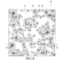
- FIG. 1A is a plan view schematically showing a base material with an antiglare film according to an example of the present invention.
- 1B is a cross-sectional view of the base material with an antiglare film as seen along the line IB-IB in FIG. 1A.
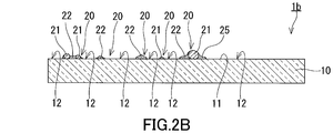
- FIG. 2A is a plan view schematically showing a base material with an antiglare film according to another example of the present invention.
- 2B is a cross-sectional view of the base material with an antiglare film as seen along the line IIB-IIB in FIG. 2A.
- the anti-glare film that provides the uneven shape covers the entire main surface of the substrate.
- the present inventor can realize good anti-glare performance when such an anti-glare film covers the entire main surface of the base material, but the glossiness of the base material with the anti-glare film in a wide range. It was newly discovered that it was difficult to adjust and it was difficult to improve the clarity of the transmitted image. Accordingly, the present inventor has made a great deal of trial and error in order to develop a new antiglare-coated substrate that is advantageous from the viewpoint of good antiglare performance, ease of adjustment of glossiness, and clarity of transmitted images. Repeated.
- the substrate with an antiglare film according to the present invention has been devised.
- the base material 1 a with an antiglare film includes a base material 10 and an antiglare film 20.
- the base material 10 has the 1st main surface 11, and a part of 1st main surface 11 is exposed. Thereby, the base material 10 has the exposed portion 12.
- the antiglare film 20 covers another part of the first main surface 11. In other words, the antiglare film 20 covers a part of the first main surface 11 different from the exposed portion 12.
- An uneven second main surface 25 is formed by the surfaces of the first main surface 11 and the antiglare film 20. When the second main surface 25 is viewed in plan, the area of the antiglare film 20 occupies 10 to 90% of the area of the second main surface 25.
- the first main surface 11 constituting the exposed portion 12 typically reflects the incident light regularly. For this reason, the glossiness of the base material 1a with the antiglare film is easily affected by the ratio of the area of the exposed portion 12 to the area of the second main surface 25 in plan view. By adjusting the area of the antiglare film 20 within the above range, it is easy to adjust the glossiness of the substrate 1a with the antiglare film over a wide range. On the other hand, since the surface of the antiglare film 20 is typically inclined with respect to the first main surface 11 to cause unevenness on the second main surface 25, the light incident on the surface of the antiglare film 20 is The first main surface 11 forming the exposed portion 12 is reflected in a direction different from the traveling direction of the light regularly reflected.
- the reflected image obtained by synthesizing the light reflected from the second main surface 25 is unclear and the antiglare film-coated substrate 1a. Can exhibit a desired anti-glare property.
- the surface of the anti-glare film 20 is inclined with respect to the first main surface 11, and the transmitted light that passes through the anti-glare film 20 easily travels by changing the course.
- a part of the transmitted light can be transmitted only through the base material 10 by the exposed portion 12.
- the transmitted light that passes only through the base material 10 is likely to travel without changing the course. This is advantageous for maintaining the sharpness of the transmitted image.
- the arithmetic average roughness Ra, the maximum height Rz, and the average length RSm of the roughness curve element defined in Japanese Industrial Standard JIS B 0601-2001 are, for example, the following (i), The conditions of (ii) and (iii) are satisfied. Thereby, the base material 1a with an anti-glare film can exhibit favorable anti-glare properties.
- the arithmetic average roughness Ra is 0.08 to 2 ⁇ m.
- the maximum height Rz is 0.5 to 15 ⁇ m.
- the average length RSm of the roughness curve elements is 15 to 50 ⁇ m.
- the arithmetic average roughness Ra may be 0.08 to 1.5 ⁇ m or 0.08 to 1 ⁇ m.
- the maximum height Rz may be 0.8 to 13 ⁇ m or 0.7 to 1.2 ⁇ m.
- the average length RSm of the roughness curve elements may be 17 to 48 ⁇ m or 20 to 45 ⁇ m.
- the arithmetic average roughness Ra in the exposed portion 12 of the first main surface 11 is, for example, 0 to 1 nm, desirably 0.1 to 0.5 nm, and more desirably 0.1 to 0.3 nm.
- the antiglare film 20 includes, for example, particles 21 and a binder 22.
- the particles 21 have a primary particle size of 0.5 to 15 ⁇ m, for example.
- the binder 22 surrounds the particles 21 in plan view. Due to the particles 21 and the binder 22, the second main surface 25 tends to have desired irregularities.
- the particles 21 may be separated from each other, or at least a part of the particles 21 may be aggregated to form secondary particles.
- the particle diameter of the secondary particles is, for example, 10 ⁇ m or less.
- the primary particle diameter and the secondary particle diameter are the maximum diameters when the antiglare film 20 is viewed in plan.
- the thickness of the binder 22 is smaller than the dimension of the particles 21 surrounded by the binder 22 in the thickness direction of the binder 22, for example.
- the thickness direction of the binder 22 may be a direction perpendicular to the first main surface 11.
- the binder 22 surrounding the particles 21 desirably forms an inclined surface that is inclined with respect to the first main surface 11.
- the thickness of the binder 22 increases gently as the distance from the particle 21 decreases in the vicinity of the particle 21. Since the binder 22 forms such an inclined surface, the second main surface 25 tends to have desired unevenness.
- the ratio (Vb / Vp) of the volume (Vb) of the binder 22 to the volume (Vp) of the particles 21 is, for example, 5/3 to 9. Thereby, the 2nd main surface 25 tends to have a desired unevenness
- the ratio (Mb / Mp) of the mass (Mb) of the binder 22 to the mass (Mp) of the particles 21 is, for example, 5/3 to 9. Thereby, the 2nd main surface 25 tends to have a desired unevenness
- the particles 21 can be formed of an organic material, an inorganic material, or a hybrid material of an organic material and an inorganic material.
- the binder 22 can be formed of an organic material, an inorganic material, or a hybrid material of an organic material and an inorganic material.
- the main component of the particles 21 is, for example, silicon dioxide (SiO 2 ).
- the main component of the binder 22 is, for example, silicon dioxide.
- the main component of the particles 21 may be silicon dioxide, and the main component of the binder 22 may be silicon dioxide.
- the particles 21 and the binder 22 tend to have a desired mechanical strength.
- the adhesion between the particles 21 and the binder 22 is good.
- the “main component” means a component that is contained most on a mass basis.
- the particles 21 may be substantially made of silicon dioxide.
- substantially consisting of silicon dioxide means that a component other than silicon dioxide is intentionally not contained except for impurities inevitably mixed in for manufacturing reasons.
- the content of components other than silicon dioxide contained in the particle 21 is, for example, 1% or less, desirably 0.1% or less, more desirably, on a mass basis. Is 0.01% or less.
- the binder 22 may contain 10% by mass or less of an organic component.
- the particles 21 are substantially made of silicon dioxide, and the binder 22 may contain 10% by mass or less of an organic component.
- the binder 22 includes, for example, a hydrolytic condensation polymer of functional alkoxysilane.
- the binder 22 can be formed by a sol-gel method.
- the substrate 10 is not particularly limited as long as it is a substrate transparent to visible light.
- the base material 10 contains glass, for example.
- the glass may be soda lime silicate glass or aluminosilicate glass.
- the substrate 10 may be a resin substrate.
- the glass may have a compressive stress layer that forms the surface of the glass.
- a compressive-stress layer can be formed by applying well-known reinforcement
- the base material 10 may include a coating film forming the first main surface 11 and a glass support that supports the coating film.
- the base material 10 is, for example, adjustment of the surface roughness of the first main surface 11, improvement in adhesion between the base material 10 and the antiglare film 20, and suppression of mass transfer between the base material 10 and the antiglare film 20.
- a coating for a predetermined purpose such as improving weather resistance of the substrate 10.
- the film is formed of, for example, an organic material, an inorganic material, or a hybrid material of an organic material and an inorganic material.
- the base material 10 is, for example, a sheet shape.
- the base material 10 may include a glass plate or a resin plate.
- the antiglare film 20 has, for example, an interconnection structure in which the antiglare film 20 and the exposed portion 12 cross each other when viewed in a plan view.
- the antiglare film 20 and the exposed portion 12 are intricately like a jigsaw puzzle piece. In this case, it is easy to increase the area of the antiglare film 20.
- the specular gloss G S (60 °) of 60 ° specular gloss specified in JIS Z 8741-1997 is, for example, 40 to 110.
- the glossiness of the base material 1a with an antiglare film can be adjusted in a wide range.
- the haze defined in JIS K 7136: 2000 is, for example, 5 to 30%.
- the haze is adjusted to an appropriate range.
- the specular gloss G S (60 °) of a glass substrate having a smooth surface is usually 150 to 160.
- a predetermined image display device can be provided using the base material 1a with an antiglare film.
- the image display device includes an image display unit having a screen and a base material 1a with an antiglare film.
- the base material 1 a with the antiglare film is disposed so that the base material 10 is positioned between the screen of the image display unit and the antiglare film 20.
- the image display unit can be, for example, a flat panel display such as a liquid crystal display and an organic EL display.
- a predetermined digital signage can be provided using the base material 1a with an antiglare film.
- the digital signage includes an image display unit having a screen and a base material 1a with an antiglare film.
- the base material 10 typically includes glass.
- the base material 1a with the antiglare film is disposed so that the base material 10 is positioned between the screen of the image display unit and the antiglare film 20.
- the image display unit can be, for example, a flat panel display such as a liquid crystal display and an organic EL display.
- the base material 1a with an antiglare film may be changed to, for example, the base material 1b with an antiglare film shown in FIGS. 2A and 2B.
- the base material 1b with an antiglare film is configured in the same manner as the base material 1a with an antiglare film, except for the part specifically described.
- the same reference numerals are given to the same or corresponding components of the base material 1b with the antiglare film as those of the base material 1a with the antiglare film, and detailed description thereof will be omitted.
- the description regarding the base material 1a with an antiglare film also applies to the base material 1b with an antiglare film as long as there is no technical contradiction.
- the antiglare film 20 has, for example, a sea-island structure dispersed in a granular shape when viewed in plan. In this case, the area of the exposed portion 12 tends to increase.
- the base material 10 for example, a glass plate or a resin plate is prepared.
- the main surface of the glass plate or the main surface of the resin plate may form the first main surface 11, and if necessary, one main surface of the glass plate or the resin plate may be subjected to a predetermined process such as polishing and coating.
- the first main surface 11 may be formed by processing.
- the antiglare film 20 is formed on the first main surface 11 of the base material 10 by, for example, a sol-gel method using a coating liquid containing a raw material for the antiglare film 20.
- the coating liquid contains particles 21 and a precursor of the binder 22.
- the precursor of the binder 22 is, for example, a functional alkoxysilane.
- the coating solution further contains, for example, an acid and water that serve as a catalyst for the gelation reaction, and may further contain a predetermined additive such as a surfactant as necessary.
- the coating liquid may contain a hydrolyzate of the functional alkoxysilane instead of the functional alkoxysilane or together with the functional alkoxysilane.
- a dispersion liquid of the particles 21 may be used.
- the dispersion medium of the dispersion liquid of the particles 21 may be a liquid organic compound such as water or alcohol.
- the coating liquid is applied to the first main surface 11 of the substrate 10 to form a coating film.
- the anti-glare film 20 is formed by curing the coating film by drying and heating.
- the base material 1a with an anti-glare film or the base material 1b with an anti-glare film is obtained.
- the method of applying the coating liquid to the first main surface 11 of the substrate 10 is, for example, a method such as roll coating, spray coating, or spraying. From the viewpoint of mass productivity, the method of applying the coating liquid to the first main surface 11 of the substrate 10 is preferably roll coating.
- the environmental temperature of the coating film when it is heated is, for example, 100 to 500 ° C.
- a stock solution A was obtained by mixing 52.01 g of normal ethyl silicate, 20.94 g of propylene glycol monomethyl ether, 26.05 g of purified water, and 1.00 g of a 1N aqueous nitric acid solution and reacting at 40 ° C. for 8 hours.
- the concentration of the solid content in the stock solution A was 15% by mass.
- the median diameter means a particle diameter (d50) at which the cumulative distribution of the volume-based particle size distribution is 50%.
- a glass plate having a general soda lime silicate composition was cut into predetermined dimensions to prepare a substrate.
- This glass plate had a smooth main surface capable of regular reflection of incident light.
- the coating liquid which concerns on Example 1 was apply
- roll coating the conveyance speed of the substrate was adjusted to 10 m / min, the rotation speed of the application roll was adjusted to 10 m / min, and the gap between the conveyance roll and the application roll was adjusted to 3.5 mm. Then, it was placed in an environment of 300 ° C. for 4 minutes using an oven to cure the coating film and form an antiglare film. In this way, a sample according to Example 1 was obtained.
- Example 2 Samples according to Examples 2 to 7 were produced in the same manner as Example 1 except for the following points.
- a dispersion B in which silica particles (manufactured by Nippon Shokubai Co., Ltd., product name: KE-P150, nominal particle diameter of silica particles: 1.5 ⁇ m) is dispersed in water. (Silica concentration: 54 mass%) was used to mix the raw materials in the amounts shown in Table 2 to prepare a coating liquid according to Example 2.
- Example 3 instead of silica particle dispersion A, silica particle dispersion C (manufactured by Nippon Shokubai Co., Ltd., product name: KE-W50, nominal particle diameter of silica particles: 0.5 ⁇ m, silica concentration: 20)
- the coating liquid according to Example 3 was prepared by mixing the raw materials in the amounts shown in Table 2.
- silica particle dispersion A as the silica particle dispersion
- the raw materials were mixed in the amounts shown in Table 2 to prepare coating solutions according to Examples 4 to 7.
- coating solutions according to Examples 4 to 7. In the formation of the antiglare film, samples according to Examples 2 to 7 were prepared using the coating liquids according to Examples 2 to 7 instead of the coating liquid according to Example 1, respectively.
- ⁇ Comparative example> A glass plate of the same type as the glass plate used as the substrate in Example 1 was cut into a predetermined size to obtain a sample according to a comparative example.
- the arithmetic average roughness Ra was on the order of several nm to several tens of nm.
- the maximum height Rz was almost 0 ⁇ m, and the average length RSm of the roughness curve element was outside the measurable range.
- the sample according to each example had antiglare properties.
- the specular gloss G S 60 °
- the haze of the sample according to the example was as low as 30% or less.
- the sample according to the example had advantageous characteristics in terms of antiglare properties, glossiness, and haze.
Landscapes
- Physics & Mathematics (AREA)
- General Physics & Mathematics (AREA)
- Optics & Photonics (AREA)
- Optical Elements Other Than Lenses (AREA)
- Liquid Crystal (AREA)
- Electroluminescent Light Sources (AREA)
- Devices For Indicating Variable Information By Combining Individual Elements (AREA)
Priority Applications (2)
| Application Number | Priority Date | Filing Date | Title |
|---|---|---|---|
| EP19819863.2A EP3809169B1 (en) | 2018-06-13 | 2019-06-12 | Anti-glare film-attached substrate, image display device, and digital signage |
| US17/251,463 US11994650B2 (en) | 2018-06-13 | 2019-06-12 | Antiglare film-attached substrate, image display apparatus, and digital signage |
Applications Claiming Priority (2)
| Application Number | Priority Date | Filing Date | Title |
|---|---|---|---|
| JP2018112649A JP7117165B2 (ja) | 2018-06-13 | 2018-06-13 | 防眩膜付基材、画像表示装置、及びデジタルサイネージ |
| JP2018-112649 | 2018-06-13 |
Publications (1)
| Publication Number | Publication Date |
|---|---|
| WO2019240178A1 true WO2019240178A1 (ja) | 2019-12-19 |
Family
ID=68842931
Family Applications (1)
| Application Number | Title | Priority Date | Filing Date |
|---|---|---|---|
| PCT/JP2019/023304 Ceased WO2019240178A1 (ja) | 2018-06-13 | 2019-06-12 | 防眩膜付基材、画像表示装置、及びデジタルサイネージ |
Country Status (4)
| Country | Link |
|---|---|
| US (1) | US11994650B2 (https=) |
| EP (1) | EP3809169B1 (https=) |
| JP (1) | JP7117165B2 (https=) |
| WO (1) | WO2019240178A1 (https=) |
Cited By (1)
| Publication number | Priority date | Publication date | Assignee | Title |
|---|---|---|---|---|
| US20230236450A1 (en) * | 2020-06-04 | 2023-07-27 | Nippon Sheet Glass Company, Limited | Display device |
Families Citing this family (8)
| Publication number | Priority date | Publication date | Assignee | Title |
|---|---|---|---|---|
| US20230126941A1 (en) * | 2020-03-16 | 2023-04-27 | Nippon Sheet Glass Company, Limited | Antiglare film-attached transparent substrate |
| CN115461800A (zh) * | 2020-04-30 | 2022-12-09 | 日本板硝子株式会社 | 显示装置 |
| JP6991416B1 (ja) | 2020-06-26 | 2022-01-13 | 日本板硝子株式会社 | 表示装置 |
| JP7661330B2 (ja) * | 2020-06-26 | 2025-04-14 | 日本板硝子株式会社 | 表示装置 |
| US12326582B2 (en) * | 2020-08-31 | 2025-06-10 | Somar Corporation | Light shielding member |
| TWI789017B (zh) * | 2021-09-17 | 2023-01-01 | 明基材料股份有限公司 | 高霧度防眩膜以及高霧度防眩抗反射膜 |
| JP2023079123A (ja) * | 2021-11-26 | 2023-06-07 | 日本板硝子株式会社 | カバー部材 |
| US20250160074A1 (en) * | 2023-11-15 | 2025-05-15 | Apple Inc. | Electronic Device with a Display Cover Layer |
Citations (11)
| Publication number | Priority date | Publication date | Assignee | Title |
|---|---|---|---|---|
| JPH10133002A (ja) | 1996-10-30 | 1998-05-22 | Canon Inc | 反射防止膜、該反射防止膜の製造方法及び該反射防止膜を用いた表示装置 |
| JP2008304638A (ja) | 2007-06-06 | 2008-12-18 | Sony Corp | 防眩性フィルムおよびその製造方法、偏光子ならびに表示装置 |
| JP2009042499A (ja) * | 2007-08-09 | 2009-02-26 | Central Glass Co Ltd | 透光性基材上に形成された光拡散性薄膜及びその製法 |
| JP2009058862A (ja) | 2007-09-03 | 2009-03-19 | Toppan Printing Co Ltd | 防眩フィルム |
| WO2013015039A1 (ja) * | 2011-07-26 | 2013-01-31 | 株式会社きもと | 静電容量式タッチパネルおよび防眩性フィルム |
| JP2013136496A (ja) | 2011-11-28 | 2013-07-11 | Nippon Sheet Glass Co Ltd | 防眩性ガラス基板およびその製造方法 |
| US20140168757A1 (en) * | 2012-12-18 | 2014-06-19 | Cheil Industries Inc. | Anti-glare film and method of fabricating the same |
| JP2015158537A (ja) | 2014-02-21 | 2015-09-03 | 旭硝子株式会社 | 防眩膜付き物品、その製造方法および画像表示装置 |
| JP2016018068A (ja) * | 2014-07-08 | 2016-02-01 | 旭硝子株式会社 | 防眩膜付き基材および物品 |
| WO2017043538A1 (ja) * | 2015-09-11 | 2017-03-16 | 日本電気硝子株式会社 | ディスプレイ用カバー部材及びその製造方法 |
| JP2018024240A (ja) * | 2016-07-28 | 2018-02-15 | 旭硝子株式会社 | 透明基材およびその製造方法 |
Family Cites Families (6)
| Publication number | Priority date | Publication date | Assignee | Title |
|---|---|---|---|---|
| JP5476948B2 (ja) | 2009-11-27 | 2014-04-23 | 大日本印刷株式会社 | 光学積層体及び光学積層体の製造方法 |
| US9446979B2 (en) | 2011-11-02 | 2016-09-20 | Corning Incorporated | Method for sparkle control and articles thereof |
| JP2013083795A (ja) * | 2011-10-11 | 2013-05-09 | Konica Minolta Advanced Layers Inc | 防眩性フィルム、防眩性フィルムの製造方法、偏光板及び画像表示装置 |
| TWI792165B (zh) | 2016-07-29 | 2023-02-11 | 日商大日本印刷股份有限公司 | 光學構件及顯示裝置 |
| JP6696486B2 (ja) * | 2016-10-07 | 2020-05-20 | Agc株式会社 | 防眩膜付基体、防眩膜形成用液状組成物及び防眩膜付基体の製造方法 |
| CN113835143B (zh) | 2016-10-07 | 2023-12-05 | Agc株式会社 | 带防眩膜的基体、用于形成防眩膜的液态组合物和带防眩膜的基体的制造方法 |
-
2018
- 2018-06-13 JP JP2018112649A patent/JP7117165B2/ja active Active
-
2019
- 2019-06-12 WO PCT/JP2019/023304 patent/WO2019240178A1/ja not_active Ceased
- 2019-06-12 EP EP19819863.2A patent/EP3809169B1/en active Active
- 2019-06-12 US US17/251,463 patent/US11994650B2/en active Active
Patent Citations (11)
| Publication number | Priority date | Publication date | Assignee | Title |
|---|---|---|---|---|
| JPH10133002A (ja) | 1996-10-30 | 1998-05-22 | Canon Inc | 反射防止膜、該反射防止膜の製造方法及び該反射防止膜を用いた表示装置 |
| JP2008304638A (ja) | 2007-06-06 | 2008-12-18 | Sony Corp | 防眩性フィルムおよびその製造方法、偏光子ならびに表示装置 |
| JP2009042499A (ja) * | 2007-08-09 | 2009-02-26 | Central Glass Co Ltd | 透光性基材上に形成された光拡散性薄膜及びその製法 |
| JP2009058862A (ja) | 2007-09-03 | 2009-03-19 | Toppan Printing Co Ltd | 防眩フィルム |
| WO2013015039A1 (ja) * | 2011-07-26 | 2013-01-31 | 株式会社きもと | 静電容量式タッチパネルおよび防眩性フィルム |
| JP2013136496A (ja) | 2011-11-28 | 2013-07-11 | Nippon Sheet Glass Co Ltd | 防眩性ガラス基板およびその製造方法 |
| US20140168757A1 (en) * | 2012-12-18 | 2014-06-19 | Cheil Industries Inc. | Anti-glare film and method of fabricating the same |
| JP2015158537A (ja) | 2014-02-21 | 2015-09-03 | 旭硝子株式会社 | 防眩膜付き物品、その製造方法および画像表示装置 |
| JP2016018068A (ja) * | 2014-07-08 | 2016-02-01 | 旭硝子株式会社 | 防眩膜付き基材および物品 |
| WO2017043538A1 (ja) * | 2015-09-11 | 2017-03-16 | 日本電気硝子株式会社 | ディスプレイ用カバー部材及びその製造方法 |
| JP2018024240A (ja) * | 2016-07-28 | 2018-02-15 | 旭硝子株式会社 | 透明基材およびその製造方法 |
Cited By (1)
| Publication number | Priority date | Publication date | Assignee | Title |
|---|---|---|---|---|
| US20230236450A1 (en) * | 2020-06-04 | 2023-07-27 | Nippon Sheet Glass Company, Limited | Display device |
Also Published As
| Publication number | Publication date |
|---|---|
| US20210255364A1 (en) | 2021-08-19 |
| JP7117165B2 (ja) | 2022-08-12 |
| EP3809169A1 (en) | 2021-04-21 |
| EP3809169A4 (en) | 2022-03-23 |
| JP2019215448A (ja) | 2019-12-19 |
| EP3809169B1 (en) | 2024-06-12 |
| US11994650B2 (en) | 2024-05-28 |
Similar Documents
| Publication | Publication Date | Title |
|---|---|---|
| JP7117165B2 (ja) | 防眩膜付基材、画像表示装置、及びデジタルサイネージ | |
| KR100799283B1 (ko) | 확산층 | |
| US7294405B2 (en) | Antiglare coating and articles | |
| EP2657011A1 (en) | Article having low reflection film | |
| JP6586897B2 (ja) | 防眩膜付き基材、膜形成用塗布液およびその製造方法 | |
| US20140002901A1 (en) | Method for producing anti-glare film, anti-glare film, polarizing plate, and image display | |
| JP5784528B2 (ja) | 防眩性ガラス基板およびその製造方法 | |
| JP6599666B2 (ja) | 光散乱性被膜を有する透明スクリーン及び光散乱性被膜形成用塗布液 | |
| WO2019156076A1 (ja) | 防眩膜付き透明基体 | |
| WO2019138751A1 (ja) | 画像表示装置 | |
| JP2017186205A (ja) | 低反射膜を有する物品 | |
| CN102650705B (zh) | 光学层压膜和显示装置 | |
| TW200839304A (en) | Light diffusion plate, light diffusion layer forming liquid, and light diffusion plate manufacturing method | |
| CN108572404B (zh) | 光学构件、摄像设备和光学构件的制造方法 | |
| EP3373048A1 (en) | Optical member, image pickup apparatus, and method for manufacturing optical member | |
| US20140002899A1 (en) | Method for producing anti-glare film, anti-glare film, coating solution, polarizing plate, and image display | |
| JP6736049B2 (ja) | ガラス複合体、それを備えた透明スクリーン、およびそれを備えた映像投影システム | |
| TW201843255A (zh) | 低折射率膜形成用液組成物及使用此組成物之低折射率膜的形成方法 | |
| JP2004352524A (ja) | 低反射物品及びその製法 | |
| WO2018003772A1 (ja) | 多結晶ナノダイヤモンドを分散させた光散乱性被膜及び光散乱性被膜形成用塗布液 | |
| KR100812593B1 (ko) | 엘시디 백라이트 유니트용 광확산 시트 | |
| WO2020039891A1 (ja) | 透明スクリーン、及びその製造方法 | |
| JP2005154749A (ja) | 導電性フィルム | |
| JP2019032355A (ja) | 光拡散板および面発光装置 |
Legal Events
| Date | Code | Title | Description |
|---|---|---|---|
| 121 | Ep: the epo has been informed by wipo that ep was designated in this application |
Ref document number: 19819863 Country of ref document: EP Kind code of ref document: A1 |
|
| NENP | Non-entry into the national phase |
Ref country code: DE |
|
| ENP | Entry into the national phase |
Ref document number: 2019819863 Country of ref document: EP Effective date: 20210113 |