WO2019240178A1 - Anti-glare film-attached substrate, image display device, and digital signage - Google Patents
Anti-glare film-attached substrate, image display device, and digital signage Download PDFInfo
- Publication number
- WO2019240178A1 WO2019240178A1 PCT/JP2019/023304 JP2019023304W WO2019240178A1 WO 2019240178 A1 WO2019240178 A1 WO 2019240178A1 JP 2019023304 W JP2019023304 W JP 2019023304W WO 2019240178 A1 WO2019240178 A1 WO 2019240178A1
- Authority
- WO
- WIPO (PCT)
- Prior art keywords
- antiglare film
- substrate
- base material
- particles
- main surface
- Prior art date
Links
- 239000000758 substrate Substances 0.000 title claims abstract description 54
- 239000000463 material Substances 0.000 claims description 78
- VYPSYNLAJGMNEJ-UHFFFAOYSA-N Silicium dioxide Chemical compound O=[Si]=O VYPSYNLAJGMNEJ-UHFFFAOYSA-N 0.000 claims description 48
- 239000002245 particle Substances 0.000 claims description 48
- 239000011230 binding agent Substances 0.000 claims description 33
- 239000011248 coating agent Substances 0.000 claims description 31
- 238000000576 coating method Methods 0.000 claims description 31
- 239000011521 glass Substances 0.000 claims description 27
- 239000000377 silicon dioxide Substances 0.000 claims description 21
- 235000012239 silicon dioxide Nutrition 0.000 claims description 13
- 239000011163 secondary particle Substances 0.000 claims description 4
- 238000004220 aggregation Methods 0.000 claims description 3
- 230000002776 aggregation Effects 0.000 claims description 3
- 239000011164 primary particle Substances 0.000 claims description 3
- HUAUNKAZQWMVFY-UHFFFAOYSA-M sodium;oxocalcium;hydroxide Chemical compound [OH-].[Na+].[Ca]=O HUAUNKAZQWMVFY-UHFFFAOYSA-M 0.000 claims description 3
- 239000005354 aluminosilicate glass Substances 0.000 claims description 2
- 239000005368 silicate glass Substances 0.000 claims description 2
- 239000007788 liquid Substances 0.000 description 15
- 230000000052 comparative effect Effects 0.000 description 9
- 239000006185 dispersion Substances 0.000 description 8
- 238000000034 method Methods 0.000 description 7
- 239000000047 product Substances 0.000 description 7
- 229910010272 inorganic material Inorganic materials 0.000 description 6
- 239000011147 inorganic material Substances 0.000 description 6
- 239000011368 organic material Substances 0.000 description 6
- 239000000243 solution Substances 0.000 description 6
- 239000011347 resin Substances 0.000 description 5
- 229920005989 resin Polymers 0.000 description 5
- XLYOFNOQVPJJNP-UHFFFAOYSA-N water Substances O XLYOFNOQVPJJNP-UHFFFAOYSA-N 0.000 description 5
- 239000002243 precursor Substances 0.000 description 4
- 239000002994 raw material Substances 0.000 description 4
- DNIAPMSPPWPWGF-UHFFFAOYSA-N Propylene glycol Chemical compound CC(O)CO DNIAPMSPPWPWGF-UHFFFAOYSA-N 0.000 description 3
- 239000010419 fine particle Substances 0.000 description 3
- 239000011159 matrix material Substances 0.000 description 3
- 238000002156 mixing Methods 0.000 description 3
- 230000003287 optical effect Effects 0.000 description 3
- 229920001610 polycaprolactone Polymers 0.000 description 3
- 238000003980 solgel method Methods 0.000 description 3
- 239000011550 stock solution Substances 0.000 description 3
- ARXJGSRGQADJSQ-UHFFFAOYSA-N 1-methoxypropan-2-ol Chemical compound COCC(C)O ARXJGSRGQADJSQ-UHFFFAOYSA-N 0.000 description 2
- 230000015572 biosynthetic process Effects 0.000 description 2
- 238000009826 distribution Methods 0.000 description 2
- 239000004973 liquid crystal related substance Substances 0.000 description 2
- 238000004519 manufacturing process Methods 0.000 description 2
- 230000002787 reinforcement Effects 0.000 description 2
- 238000005507 spraying Methods 0.000 description 2
- 238000005728 strengthening Methods 0.000 description 2
- 239000004094 surface-active agent Substances 0.000 description 2
- BPSIOYPQMFLKFR-UHFFFAOYSA-N trimethoxy-[3-(oxiran-2-ylmethoxy)propyl]silane Chemical compound CO[Si](OC)(OC)CCCOCC1CO1 BPSIOYPQMFLKFR-UHFFFAOYSA-N 0.000 description 2
- LFQSCWFLJHTTHZ-UHFFFAOYSA-N Ethanol Chemical compound CCO LFQSCWFLJHTTHZ-UHFFFAOYSA-N 0.000 description 1
- GRYLNZFGIOXLOG-UHFFFAOYSA-N Nitric acid Chemical compound O[N+]([O-])=O GRYLNZFGIOXLOG-UHFFFAOYSA-N 0.000 description 1
- BPQQTUXANYXVAA-UHFFFAOYSA-N Orthosilicate Chemical compound [O-][Si]([O-])([O-])[O-] BPQQTUXANYXVAA-UHFFFAOYSA-N 0.000 description 1
- 229910004298 SiO 2 Inorganic materials 0.000 description 1
- BOTDANWDWHJENH-UHFFFAOYSA-N Tetraethyl orthosilicate Chemical compound CCO[Si](OCC)(OCC)OCC BOTDANWDWHJENH-UHFFFAOYSA-N 0.000 description 1
- XSTXAVWGXDQKEL-UHFFFAOYSA-N Trichloroethylene Chemical compound ClC=C(Cl)Cl XSTXAVWGXDQKEL-UHFFFAOYSA-N 0.000 description 1
- 239000002253 acid Substances 0.000 description 1
- 239000000654 additive Substances 0.000 description 1
- 230000000996 additive effect Effects 0.000 description 1
- 239000003054 catalyst Substances 0.000 description 1
- 238000006243 chemical reaction Methods 0.000 description 1
- 238000003426 chemical strengthening reaction Methods 0.000 description 1
- 238000009833 condensation Methods 0.000 description 1
- 230000005494 condensation Effects 0.000 description 1
- 238000001816 cooling Methods 0.000 description 1
- 230000001186 cumulative effect Effects 0.000 description 1
- 230000007423 decrease Effects 0.000 description 1
- 239000002612 dispersion medium Substances 0.000 description 1
- 238000001035 drying Methods 0.000 description 1
- 230000000694 effects Effects 0.000 description 1
- 230000007613 environmental effect Effects 0.000 description 1
- 238000011156 evaluation Methods 0.000 description 1
- 230000001747 exhibiting effect Effects 0.000 description 1
- 230000002349 favourable effect Effects 0.000 description 1
- 238000010304 firing Methods 0.000 description 1
- 238000001879 gelation Methods 0.000 description 1
- 238000010438 heat treatment Methods 0.000 description 1
- 230000003301 hydrolyzing effect Effects 0.000 description 1
- 238000005286 illumination Methods 0.000 description 1
- 239000012535 impurity Substances 0.000 description 1
- 239000010954 inorganic particle Substances 0.000 description 1
- 239000000203 mixture Substances 0.000 description 1
- 229910017604 nitric acid Inorganic materials 0.000 description 1
- 150000002894 organic compounds Chemical class 0.000 description 1
- 239000012466 permeate Substances 0.000 description 1
- 229920003023 plastic Polymers 0.000 description 1
- 239000004033 plastic Substances 0.000 description 1
- 238000005498 polishing Methods 0.000 description 1
- 239000004632 polycaprolactone Substances 0.000 description 1
- 229920000642 polymer Polymers 0.000 description 1
- 229920001296 polysiloxane Polymers 0.000 description 1
- 238000002360 preparation method Methods 0.000 description 1
- 239000008213 purified water Substances 0.000 description 1
- 239000007787 solid Substances 0.000 description 1
- 230000001629 suppression Effects 0.000 description 1
- 230000003746 surface roughness Effects 0.000 description 1
- 230000002194 synthesizing effect Effects 0.000 description 1
- 238000002834 transmittance Methods 0.000 description 1
Images


Classifications
-
- G—PHYSICS
- G02—OPTICS
- G02B—OPTICAL ELEMENTS, SYSTEMS OR APPARATUS
- G02B1/00—Optical elements characterised by the material of which they are made; Optical coatings for optical elements
- G02B1/10—Optical coatings produced by application to, or surface treatment of, optical elements
- G02B1/11—Anti-reflection coatings
-
- G—PHYSICS
- G02—OPTICS
- G02B—OPTICAL ELEMENTS, SYSTEMS OR APPARATUS
- G02B5/00—Optical elements other than lenses
- G02B5/02—Diffusing elements; Afocal elements
- G02B5/0205—Diffusing elements; Afocal elements characterised by the diffusing properties
- G02B5/021—Diffusing elements; Afocal elements characterised by the diffusing properties the diffusion taking place at the element's surface, e.g. by means of surface roughening or microprismatic structures
- G02B5/0221—Diffusing elements; Afocal elements characterised by the diffusing properties the diffusion taking place at the element's surface, e.g. by means of surface roughening or microprismatic structures the surface having an irregular structure
-
- G—PHYSICS
- G02—OPTICS
- G02B—OPTICAL ELEMENTS, SYSTEMS OR APPARATUS
- G02B5/00—Optical elements other than lenses
- G02B5/02—Diffusing elements; Afocal elements
- G02B5/0273—Diffusing elements; Afocal elements characterized by the use
- G02B5/0294—Diffusing elements; Afocal elements characterized by the use adapted to provide an additional optical effect, e.g. anti-reflection or filter
-
- H—ELECTRICITY
- H10—SEMICONDUCTOR DEVICES; ELECTRIC SOLID-STATE DEVICES NOT OTHERWISE PROVIDED FOR
- H10K—ORGANIC ELECTRIC SOLID-STATE DEVICES
- H10K59/00—Integrated devices, or assemblies of multiple devices, comprising at least one organic light-emitting element covered by group H10K50/00
- H10K59/80—Constructional details
- H10K59/8791—Arrangements for improving contrast, e.g. preventing reflection of ambient light
-
- G—PHYSICS
- G02—OPTICS
- G02B—OPTICAL ELEMENTS, SYSTEMS OR APPARATUS
- G02B2207/00—Coding scheme for general features or characteristics of optical elements and systems of subclass G02B, but not including elements and systems which would be classified in G02B6/00 and subgroups
- G02B2207/109—Sols, gels, sol-gel materials
-
- G—PHYSICS
- G02—OPTICS
- G02B—OPTICAL ELEMENTS, SYSTEMS OR APPARATUS
- G02B5/00—Optical elements other than lenses
- G02B5/02—Diffusing elements; Afocal elements
- G02B5/0205—Diffusing elements; Afocal elements characterised by the diffusing properties
- G02B5/021—Diffusing elements; Afocal elements characterised by the diffusing properties the diffusion taking place at the element's surface, e.g. by means of surface roughening or microprismatic structures
- G02B5/0226—Diffusing elements; Afocal elements characterised by the diffusing properties the diffusion taking place at the element's surface, e.g. by means of surface roughening or microprismatic structures having particles on the surface
-
- G—PHYSICS
- G02—OPTICS
- G02B—OPTICAL ELEMENTS, SYSTEMS OR APPARATUS
- G02B5/00—Optical elements other than lenses
- G02B5/02—Diffusing elements; Afocal elements
- G02B5/0205—Diffusing elements; Afocal elements characterised by the diffusing properties
- G02B5/0236—Diffusing elements; Afocal elements characterised by the diffusing properties the diffusion taking place within the volume of the element
- G02B5/0242—Diffusing elements; Afocal elements characterised by the diffusing properties the diffusion taking place within the volume of the element by means of dispersed particles
-
- G—PHYSICS
- G02—OPTICS
- G02F—OPTICAL DEVICES OR ARRANGEMENTS FOR THE CONTROL OF LIGHT BY MODIFICATION OF THE OPTICAL PROPERTIES OF THE MEDIA OF THE ELEMENTS INVOLVED THEREIN; NON-LINEAR OPTICS; FREQUENCY-CHANGING OF LIGHT; OPTICAL LOGIC ELEMENTS; OPTICAL ANALOGUE/DIGITAL CONVERTERS
- G02F1/00—Devices or arrangements for the control of the intensity, colour, phase, polarisation or direction of light arriving from an independent light source, e.g. switching, gating or modulating; Non-linear optics
- G02F1/01—Devices or arrangements for the control of the intensity, colour, phase, polarisation or direction of light arriving from an independent light source, e.g. switching, gating or modulating; Non-linear optics for the control of the intensity, phase, polarisation or colour
- G02F1/13—Devices or arrangements for the control of the intensity, colour, phase, polarisation or direction of light arriving from an independent light source, e.g. switching, gating or modulating; Non-linear optics for the control of the intensity, phase, polarisation or colour based on liquid crystals, e.g. single liquid crystal display cells
- G02F1/133—Constructional arrangements; Operation of liquid crystal cells; Circuit arrangements
- G02F1/1333—Constructional arrangements; Manufacturing methods
- G02F1/1335—Structural association of cells with optical devices, e.g. polarisers or reflectors
- G02F1/133502—Antiglare, refractive index matching layers
-
- G—PHYSICS
- G09—EDUCATION; CRYPTOGRAPHY; DISPLAY; ADVERTISING; SEALS
- G09F—DISPLAYING; ADVERTISING; SIGNS; LABELS OR NAME-PLATES; SEALS
- G09F9/00—Indicating arrangements for variable information in which the information is built-up on a support by selection or combination of individual elements
Definitions
- the present invention relates to a substrate with an antiglare film, an image display device, and digital signage.
- the base material used for the image display device and the digital signage is required to improve the visibility of the display image by preventing the illumination device such as a fluorescent lamp or the background from being reflected on the surface. From such a viewpoint, it is known to form an antiglare film on the surface of a substrate.
- Patent Document 1 describes an article having an antiglare film on the surface of a substrate.
- the haze of the article is 15% or more, and the 60 ° specular gloss on the surface of the antiglare film is 25% or less.
- the arithmetic average roughness Ra of the surface of the antiglare film is 0.17 ⁇ m or more.
- the antiglare film is a film having irregularities on the surface, in which inorganic particles are present in a matrix formed by firing a matrix precursor such as a silica precursor.
- the surface has a fine uneven shape, the average inclination angle ⁇ a on the surface is 0.2 ° to 1.5 °, and the arithmetic average roughness Ra is 0.05 to 0.4.
- An antiglare film is described.
- the fine uneven shape is formed by aggregation of fine particles.
- corrugated shape is formed by the Benard cell formation method, for example.
- Patent Document 3 describes an antiglare film having an antiglare layer containing particles and a binder matrix on a transparent substrate.
- the antiglare layer has a concavo-convex structure exhibiting a predetermined ten-point average roughness (Rz 1 ) with respect to a predetermined cutoff wavelength ( ⁇ c).
- Patent Document 4 describes an antireflection film capable of obtaining a good antiglare effect.
- This antireflection film is formed by mixing fine particles with a sol solution prepared by a sol-gel method, coating the substrate on a substrate, and baking it.
- the surface of the antireflection film is formed in a concavo-convex shape with a predetermined pitch by aggregation of fine particles. For example, about 150 to 300 particles are aggregated to form an aggregate.
- Patent Document 5 describes an antiglare glass substrate comprising a glass substrate and a transparent layer formed on the surface of the glass substrate.
- the 1st uneven surface which is the surface of a glass substrate, and the 2nd uneven surface which is the surface of a transparent layer have predetermined arithmetic mean roughness (Ra) and pitch (Sm).
- the entire main surface of the substrate is covered with an antiglare film or the like, and it is not assumed that transmitted light passes only through the substrate.
- this invention provides the base material with an anti-glare film which has anti-glare property and a part of transmitted light can permeate
- the present invention provides an image display device and a digital signage provided with such a substrate with an antiglare film.
- the present invention A substrate having a first major surface partially exposed; An anti-glare film covering another part of the first main surface, Having an uneven second main surface formed by the surface of the first main surface and the antiglare film, When the second main surface is viewed in plan, the area of the antiglare film occupies 10 to 90% of the area of the second main surface.
- a base material with an antiglare film is provided.
- the present invention also provides: An image display unit having a screen; The above-mentioned base material with an antiglare film, which is disposed so that the base material is positioned between the screen and the antiglare film, An image display device is provided.
- the present invention also provides: An image display unit having a screen;
- the base material is a base material with an antiglare film containing glass, and the base material with an antiglare film is disposed so that the base material is positioned between the screen and the antiglare film, With Provide digital signage.
- the above-mentioned substrate with antiglare film has antiglare properties due to the antiglare film.
- a part of the first main surface of the base material is exposed, a part of the transmitted light can pass only through the base material.
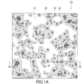
- FIG. 1A is a plan view schematically showing a base material with an antiglare film according to an example of the present invention.
- 1B is a cross-sectional view of the base material with an antiglare film as seen along the line IB-IB in FIG. 1A.
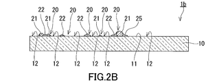
- FIG. 2A is a plan view schematically showing a base material with an antiglare film according to another example of the present invention.
- 2B is a cross-sectional view of the base material with an antiglare film as seen along the line IIB-IIB in FIG. 2A.
- the anti-glare film that provides the uneven shape covers the entire main surface of the substrate.
- the present inventor can realize good anti-glare performance when such an anti-glare film covers the entire main surface of the base material, but the glossiness of the base material with the anti-glare film in a wide range. It was newly discovered that it was difficult to adjust and it was difficult to improve the clarity of the transmitted image. Accordingly, the present inventor has made a great deal of trial and error in order to develop a new antiglare-coated substrate that is advantageous from the viewpoint of good antiglare performance, ease of adjustment of glossiness, and clarity of transmitted images. Repeated.
- the substrate with an antiglare film according to the present invention has been devised.
- the base material 1 a with an antiglare film includes a base material 10 and an antiglare film 20.
- the base material 10 has the 1st main surface 11, and a part of 1st main surface 11 is exposed. Thereby, the base material 10 has the exposed portion 12.
- the antiglare film 20 covers another part of the first main surface 11. In other words, the antiglare film 20 covers a part of the first main surface 11 different from the exposed portion 12.
- An uneven second main surface 25 is formed by the surfaces of the first main surface 11 and the antiglare film 20. When the second main surface 25 is viewed in plan, the area of the antiglare film 20 occupies 10 to 90% of the area of the second main surface 25.
- the first main surface 11 constituting the exposed portion 12 typically reflects the incident light regularly. For this reason, the glossiness of the base material 1a with the antiglare film is easily affected by the ratio of the area of the exposed portion 12 to the area of the second main surface 25 in plan view. By adjusting the area of the antiglare film 20 within the above range, it is easy to adjust the glossiness of the substrate 1a with the antiglare film over a wide range. On the other hand, since the surface of the antiglare film 20 is typically inclined with respect to the first main surface 11 to cause unevenness on the second main surface 25, the light incident on the surface of the antiglare film 20 is The first main surface 11 forming the exposed portion 12 is reflected in a direction different from the traveling direction of the light regularly reflected.
- the reflected image obtained by synthesizing the light reflected from the second main surface 25 is unclear and the antiglare film-coated substrate 1a. Can exhibit a desired anti-glare property.
- the surface of the anti-glare film 20 is inclined with respect to the first main surface 11, and the transmitted light that passes through the anti-glare film 20 easily travels by changing the course.
- a part of the transmitted light can be transmitted only through the base material 10 by the exposed portion 12.
- the transmitted light that passes only through the base material 10 is likely to travel without changing the course. This is advantageous for maintaining the sharpness of the transmitted image.
- the arithmetic average roughness Ra, the maximum height Rz, and the average length RSm of the roughness curve element defined in Japanese Industrial Standard JIS B 0601-2001 are, for example, the following (i), The conditions of (ii) and (iii) are satisfied. Thereby, the base material 1a with an anti-glare film can exhibit favorable anti-glare properties.
- the arithmetic average roughness Ra is 0.08 to 2 ⁇ m.
- the maximum height Rz is 0.5 to 15 ⁇ m.
- the average length RSm of the roughness curve elements is 15 to 50 ⁇ m.
- the arithmetic average roughness Ra may be 0.08 to 1.5 ⁇ m or 0.08 to 1 ⁇ m.
- the maximum height Rz may be 0.8 to 13 ⁇ m or 0.7 to 1.2 ⁇ m.
- the average length RSm of the roughness curve elements may be 17 to 48 ⁇ m or 20 to 45 ⁇ m.
- the arithmetic average roughness Ra in the exposed portion 12 of the first main surface 11 is, for example, 0 to 1 nm, desirably 0.1 to 0.5 nm, and more desirably 0.1 to 0.3 nm.
- the antiglare film 20 includes, for example, particles 21 and a binder 22.
- the particles 21 have a primary particle size of 0.5 to 15 ⁇ m, for example.
- the binder 22 surrounds the particles 21 in plan view. Due to the particles 21 and the binder 22, the second main surface 25 tends to have desired irregularities.
- the particles 21 may be separated from each other, or at least a part of the particles 21 may be aggregated to form secondary particles.
- the particle diameter of the secondary particles is, for example, 10 ⁇ m or less.
- the primary particle diameter and the secondary particle diameter are the maximum diameters when the antiglare film 20 is viewed in plan.
- the thickness of the binder 22 is smaller than the dimension of the particles 21 surrounded by the binder 22 in the thickness direction of the binder 22, for example.
- the thickness direction of the binder 22 may be a direction perpendicular to the first main surface 11.
- the binder 22 surrounding the particles 21 desirably forms an inclined surface that is inclined with respect to the first main surface 11.
- the thickness of the binder 22 increases gently as the distance from the particle 21 decreases in the vicinity of the particle 21. Since the binder 22 forms such an inclined surface, the second main surface 25 tends to have desired unevenness.
- the ratio (Vb / Vp) of the volume (Vb) of the binder 22 to the volume (Vp) of the particles 21 is, for example, 5/3 to 9. Thereby, the 2nd main surface 25 tends to have a desired unevenness
- the ratio (Mb / Mp) of the mass (Mb) of the binder 22 to the mass (Mp) of the particles 21 is, for example, 5/3 to 9. Thereby, the 2nd main surface 25 tends to have a desired unevenness
- the particles 21 can be formed of an organic material, an inorganic material, or a hybrid material of an organic material and an inorganic material.
- the binder 22 can be formed of an organic material, an inorganic material, or a hybrid material of an organic material and an inorganic material.
- the main component of the particles 21 is, for example, silicon dioxide (SiO 2 ).
- the main component of the binder 22 is, for example, silicon dioxide.
- the main component of the particles 21 may be silicon dioxide, and the main component of the binder 22 may be silicon dioxide.
- the particles 21 and the binder 22 tend to have a desired mechanical strength.
- the adhesion between the particles 21 and the binder 22 is good.
- the “main component” means a component that is contained most on a mass basis.
- the particles 21 may be substantially made of silicon dioxide.
- substantially consisting of silicon dioxide means that a component other than silicon dioxide is intentionally not contained except for impurities inevitably mixed in for manufacturing reasons.
- the content of components other than silicon dioxide contained in the particle 21 is, for example, 1% or less, desirably 0.1% or less, more desirably, on a mass basis. Is 0.01% or less.
- the binder 22 may contain 10% by mass or less of an organic component.
- the particles 21 are substantially made of silicon dioxide, and the binder 22 may contain 10% by mass or less of an organic component.
- the binder 22 includes, for example, a hydrolytic condensation polymer of functional alkoxysilane.
- the binder 22 can be formed by a sol-gel method.
- the substrate 10 is not particularly limited as long as it is a substrate transparent to visible light.
- the base material 10 contains glass, for example.
- the glass may be soda lime silicate glass or aluminosilicate glass.
- the substrate 10 may be a resin substrate.
- the glass may have a compressive stress layer that forms the surface of the glass.
- a compressive-stress layer can be formed by applying well-known reinforcement
- the base material 10 may include a coating film forming the first main surface 11 and a glass support that supports the coating film.
- the base material 10 is, for example, adjustment of the surface roughness of the first main surface 11, improvement in adhesion between the base material 10 and the antiglare film 20, and suppression of mass transfer between the base material 10 and the antiglare film 20.
- a coating for a predetermined purpose such as improving weather resistance of the substrate 10.
- the film is formed of, for example, an organic material, an inorganic material, or a hybrid material of an organic material and an inorganic material.
- the base material 10 is, for example, a sheet shape.
- the base material 10 may include a glass plate or a resin plate.
- the antiglare film 20 has, for example, an interconnection structure in which the antiglare film 20 and the exposed portion 12 cross each other when viewed in a plan view.
- the antiglare film 20 and the exposed portion 12 are intricately like a jigsaw puzzle piece. In this case, it is easy to increase the area of the antiglare film 20.
- the specular gloss G S (60 °) of 60 ° specular gloss specified in JIS Z 8741-1997 is, for example, 40 to 110.
- the glossiness of the base material 1a with an antiglare film can be adjusted in a wide range.
- the haze defined in JIS K 7136: 2000 is, for example, 5 to 30%.
- the haze is adjusted to an appropriate range.
- the specular gloss G S (60 °) of a glass substrate having a smooth surface is usually 150 to 160.
- a predetermined image display device can be provided using the base material 1a with an antiglare film.
- the image display device includes an image display unit having a screen and a base material 1a with an antiglare film.
- the base material 1 a with the antiglare film is disposed so that the base material 10 is positioned between the screen of the image display unit and the antiglare film 20.
- the image display unit can be, for example, a flat panel display such as a liquid crystal display and an organic EL display.
- a predetermined digital signage can be provided using the base material 1a with an antiglare film.
- the digital signage includes an image display unit having a screen and a base material 1a with an antiglare film.
- the base material 10 typically includes glass.
- the base material 1a with the antiglare film is disposed so that the base material 10 is positioned between the screen of the image display unit and the antiglare film 20.
- the image display unit can be, for example, a flat panel display such as a liquid crystal display and an organic EL display.
- the base material 1a with an antiglare film may be changed to, for example, the base material 1b with an antiglare film shown in FIGS. 2A and 2B.
- the base material 1b with an antiglare film is configured in the same manner as the base material 1a with an antiglare film, except for the part specifically described.
- the same reference numerals are given to the same or corresponding components of the base material 1b with the antiglare film as those of the base material 1a with the antiglare film, and detailed description thereof will be omitted.
- the description regarding the base material 1a with an antiglare film also applies to the base material 1b with an antiglare film as long as there is no technical contradiction.
- the antiglare film 20 has, for example, a sea-island structure dispersed in a granular shape when viewed in plan. In this case, the area of the exposed portion 12 tends to increase.
- the base material 10 for example, a glass plate or a resin plate is prepared.
- the main surface of the glass plate or the main surface of the resin plate may form the first main surface 11, and if necessary, one main surface of the glass plate or the resin plate may be subjected to a predetermined process such as polishing and coating.
- the first main surface 11 may be formed by processing.
- the antiglare film 20 is formed on the first main surface 11 of the base material 10 by, for example, a sol-gel method using a coating liquid containing a raw material for the antiglare film 20.
- the coating liquid contains particles 21 and a precursor of the binder 22.
- the precursor of the binder 22 is, for example, a functional alkoxysilane.
- the coating solution further contains, for example, an acid and water that serve as a catalyst for the gelation reaction, and may further contain a predetermined additive such as a surfactant as necessary.
- the coating liquid may contain a hydrolyzate of the functional alkoxysilane instead of the functional alkoxysilane or together with the functional alkoxysilane.
- a dispersion liquid of the particles 21 may be used.
- the dispersion medium of the dispersion liquid of the particles 21 may be a liquid organic compound such as water or alcohol.
- the coating liquid is applied to the first main surface 11 of the substrate 10 to form a coating film.
- the anti-glare film 20 is formed by curing the coating film by drying and heating.
- the base material 1a with an anti-glare film or the base material 1b with an anti-glare film is obtained.
- the method of applying the coating liquid to the first main surface 11 of the substrate 10 is, for example, a method such as roll coating, spray coating, or spraying. From the viewpoint of mass productivity, the method of applying the coating liquid to the first main surface 11 of the substrate 10 is preferably roll coating.
- the environmental temperature of the coating film when it is heated is, for example, 100 to 500 ° C.
- a stock solution A was obtained by mixing 52.01 g of normal ethyl silicate, 20.94 g of propylene glycol monomethyl ether, 26.05 g of purified water, and 1.00 g of a 1N aqueous nitric acid solution and reacting at 40 ° C. for 8 hours.
- the concentration of the solid content in the stock solution A was 15% by mass.
- the median diameter means a particle diameter (d50) at which the cumulative distribution of the volume-based particle size distribution is 50%.
- a glass plate having a general soda lime silicate composition was cut into predetermined dimensions to prepare a substrate.
- This glass plate had a smooth main surface capable of regular reflection of incident light.
- the coating liquid which concerns on Example 1 was apply
- roll coating the conveyance speed of the substrate was adjusted to 10 m / min, the rotation speed of the application roll was adjusted to 10 m / min, and the gap between the conveyance roll and the application roll was adjusted to 3.5 mm. Then, it was placed in an environment of 300 ° C. for 4 minutes using an oven to cure the coating film and form an antiglare film. In this way, a sample according to Example 1 was obtained.
- Example 2 Samples according to Examples 2 to 7 were produced in the same manner as Example 1 except for the following points.
- a dispersion B in which silica particles (manufactured by Nippon Shokubai Co., Ltd., product name: KE-P150, nominal particle diameter of silica particles: 1.5 ⁇ m) is dispersed in water. (Silica concentration: 54 mass%) was used to mix the raw materials in the amounts shown in Table 2 to prepare a coating liquid according to Example 2.
- Example 3 instead of silica particle dispersion A, silica particle dispersion C (manufactured by Nippon Shokubai Co., Ltd., product name: KE-W50, nominal particle diameter of silica particles: 0.5 ⁇ m, silica concentration: 20)
- the coating liquid according to Example 3 was prepared by mixing the raw materials in the amounts shown in Table 2.
- silica particle dispersion A as the silica particle dispersion
- the raw materials were mixed in the amounts shown in Table 2 to prepare coating solutions according to Examples 4 to 7.
- coating solutions according to Examples 4 to 7. In the formation of the antiglare film, samples according to Examples 2 to 7 were prepared using the coating liquids according to Examples 2 to 7 instead of the coating liquid according to Example 1, respectively.
- ⁇ Comparative example> A glass plate of the same type as the glass plate used as the substrate in Example 1 was cut into a predetermined size to obtain a sample according to a comparative example.
- the arithmetic average roughness Ra was on the order of several nm to several tens of nm.
- the maximum height Rz was almost 0 ⁇ m, and the average length RSm of the roughness curve element was outside the measurable range.
- the sample according to each example had antiglare properties.
- the specular gloss G S 60 °
- the haze of the sample according to the example was as low as 30% or less.
- the sample according to the example had advantageous characteristics in terms of antiglare properties, glossiness, and haze.
Abstract
An anti-glare film-attached substrate (1a) comprises a substrate (10) and an anti-glare film (20). The substrate (10) has a first main surface (11), and a part of the first main surface (11) is exposed. The anti-glare film (20) covers another part of the first main surface (11). The anti-glare film-attached substrate (1a) has a second main surface (25) that is constituted of surfaces of the first main surface (11) and of the anti-glare film (20), and that has recesses and projections. When the second main surface (25) is observed in plan view, the area of the anti-glare film (20) accounts for 10-90% of the second main surface (25).
Description
本発明は、防眩膜付基材、画像表示装置、及びデジタルサイネージに関する。
The present invention relates to a substrate with an antiglare film, an image display device, and digital signage.
画像表示装置及びデジタルサイネージに用いられる基材には、その表面に蛍光灯等の照明機器又は背景が映り込むことを防止して、表示画像の視認性を向上させることが求められる。このような観点から、基材の表面に防眩膜を形成することが知られている。
The base material used for the image display device and the digital signage is required to improve the visibility of the display image by preventing the illumination device such as a fluorescent lamp or the background from being reflected on the surface. From such a viewpoint, it is known to form an antiglare film on the surface of a substrate.
例えば、特許文献1には、基材の表面に防眩膜を有する物品が記載されている。物品のヘーズは15%以上であり、防眩膜の表面における60゜鏡面光沢度は25%以下である。防眩膜の表面の算術平均粗さRaは0.17μm以上である。防眩膜は、例えば、シリカ前駆体等のマトリックス前駆体を焼成して形成されたマトリックスの中に無機粒子が存在する、表面に凹凸を有する膜である。
For example, Patent Document 1 describes an article having an antiglare film on the surface of a substrate. The haze of the article is 15% or more, and the 60 ° specular gloss on the surface of the antiglare film is 25% or less. The arithmetic average roughness Ra of the surface of the antiglare film is 0.17 μm or more. The antiglare film is a film having irregularities on the surface, in which inorganic particles are present in a matrix formed by firing a matrix precursor such as a silica precursor.
特許文献2には、表面に微細凹凸形状を有し、該表面における平均傾斜角θaが0.2°~1.5°であり、かつ、算術平均粗さRaが0.05~0.4である防眩性フィルムが記載されている。微細凹凸形状は、微粒子の凝集により形成されている。また、微細凹凸形状は、例えば、べナードセル形成法によって形成されている。
In Patent Document 2, the surface has a fine uneven shape, the average inclination angle θa on the surface is 0.2 ° to 1.5 °, and the arithmetic average roughness Ra is 0.05 to 0.4. An antiglare film is described. The fine uneven shape is formed by aggregation of fine particles. Moreover, the fine uneven | corrugated shape is formed by the Benard cell formation method, for example.
特許文献3には、透明基材上に粒子とバインダマトリックスを含む防眩層を備える防眩フィルムが記載されている。防眩層は、所定のカットオフ波長(λc)に対して所定の十点平均粗さ(Rz1)を示す凹凸構造を備えている。
Patent Document 3 describes an antiglare film having an antiglare layer containing particles and a binder matrix on a transparent substrate. The antiglare layer has a concavo-convex structure exhibiting a predetermined ten-point average roughness (Rz 1 ) with respect to a predetermined cutoff wavelength (λc).
特許文献4には、良好なアンチグレア効果を得ることができる反射防止膜が記載されている。この反射防止膜は、微粒子をゾルゲル法による調整後のゾル液に混合し、それを基板上にコーティング、焼成することにより形成されている。反射防止膜において、微粒子の凝集により反射防止膜の表面が所定ピッチの凹凸状に形成されている。例えば、約150~300個の粒子が集合して凝集体が形成されている。
Patent Document 4 describes an antireflection film capable of obtaining a good antiglare effect. This antireflection film is formed by mixing fine particles with a sol solution prepared by a sol-gel method, coating the substrate on a substrate, and baking it. In the antireflection film, the surface of the antireflection film is formed in a concavo-convex shape with a predetermined pitch by aggregation of fine particles. For example, about 150 to 300 particles are aggregated to form an aggregate.
特許文献5には、ガラス基板と、ガラス基板の表面に形成された透明層とを備える防眩性ガラス基板が記載されている。ガラス基板の表面である第一凹凸面及び透明層の表面である第二凹凸面が所定の算術平均粗さ(Ra)及びピッチ(Sm)を有している。
Patent Document 5 describes an antiglare glass substrate comprising a glass substrate and a transparent layer formed on the surface of the glass substrate. The 1st uneven surface which is the surface of a glass substrate, and the 2nd uneven surface which is the surface of a transparent layer have predetermined arithmetic mean roughness (Ra) and pitch (Sm).
特許文献1~5に記載の技術によれば、基材の主面の全体が防眩膜等によって覆われており、透過光線が基材のみを透過することは想定されていない。そこで、本発明は、防眩性を有するとともに、透過光線の一部が基材のみを透過可能である防眩膜付基材を提供する。加えて、本発明は、このような防眩膜付基材を備えた画像表示装置及びデジタルサイネージを提供する。
According to the techniques described in Patent Documents 1 to 5, the entire main surface of the substrate is covered with an antiglare film or the like, and it is not assumed that transmitted light passes only through the substrate. Then, this invention provides the base material with an anti-glare film which has anti-glare property and a part of transmitted light can permeate | transmit only a base material. In addition, the present invention provides an image display device and a digital signage provided with such a substrate with an antiglare film.
本発明は、
一部が露出している第一主面を有する基材と、
前記第一主面の別の一部を覆う防眩膜と、を備え、
前記第一主面及び前記防眩膜の表面によって形成された凹凸のある第二主面を有し、
前記第二主面を平面視したときに、前記防眩膜の面積は、前記第二主面の面積の10~90%を占めている、
防眩膜付基材を提供する。 The present invention
A substrate having a first major surface partially exposed;
An anti-glare film covering another part of the first main surface,
Having an uneven second main surface formed by the surface of the first main surface and the antiglare film,
When the second main surface is viewed in plan, the area of the antiglare film occupies 10 to 90% of the area of the second main surface.
A base material with an antiglare film is provided.
また、本発明は、
画面を有する画像表示ユニットと、
前記画面と前記防眩膜との間に前記基材が位置するように配置された、上記の防眩膜付基材と、を備えた、
画像表示装置を提供する。 The present invention also provides:
An image display unit having a screen;
The above-mentioned base material with an antiglare film, which is disposed so that the base material is positioned between the screen and the antiglare film,
An image display device is provided.
また、本発明は、
画面を有する画像表示ユニットと、
前記基材がガラスを含む上記の防眩膜付基材であって、前記画面と前記防眩膜との間に前記基材が位置するように配置された、防眩膜付基材と、を備えた、
デジタルサイネージを提供する。 The present invention also provides:
An image display unit having a screen;
The base material is a base material with an antiglare film containing glass, and the base material with an antiglare film is disposed so that the base material is positioned between the screen and the antiglare film, With
Provide digital signage.
上記の防眩膜付基材は防眩膜によって防眩性を有する。加えて、基材の第一主面の一部が露出しているので、透過光線の一部が基材のみを透過可能である。
The above-mentioned substrate with antiglare film has antiglare properties due to the antiglare film. In addition, since a part of the first main surface of the base material is exposed, a part of the transmitted light can pass only through the base material.
以下、本発明の実施形態について図面を参照しながら説明する。なお、以下の説明は、本発明の一例に関するものであり、本発明は以下の実施形態に限定されない。
Hereinafter, embodiments of the present invention will be described with reference to the drawings. The following description relates to an example of the present invention, and the present invention is not limited to the following embodiment.
所定の凹凸形状を有する防眩構造により良好な防眩性能を実現するためには、凹凸形状をもたらす防眩膜が基材の主面の全体を覆っていることが望ましいように思われる。一方、本発明者は、このような防眩膜が基材の主面の全体を覆っていると、良好な防眩性能を実現できるものの、防眩膜付基材の光沢感を広い範囲で調整しにくく、透過像の鮮明さを向上させにくいことに新たに気付いた。そこで、本発明者は、良好な防眩性能、光沢感の調整のしやすさ、及び透過像の鮮明さの観点から有利な防眩膜付基材を新規に開発すべく、多大な試行錯誤を重ねた。その結果、本発明者は、基材の主面の一部を露出させつつ、基材の主面を覆う防眩膜の面積を所定の範囲に調整することが有利であることを新たに見出し、本発明に係る防眩膜付基材を案出した。
In order to realize a good anti-glare performance by the anti-glare structure having a predetermined uneven shape, it seems desirable that the anti-glare film that provides the uneven shape covers the entire main surface of the substrate. On the other hand, the present inventor can realize good anti-glare performance when such an anti-glare film covers the entire main surface of the base material, but the glossiness of the base material with the anti-glare film in a wide range. It was newly discovered that it was difficult to adjust and it was difficult to improve the clarity of the transmitted image. Accordingly, the present inventor has made a great deal of trial and error in order to develop a new antiglare-coated substrate that is advantageous from the viewpoint of good antiglare performance, ease of adjustment of glossiness, and clarity of transmitted images. Repeated. As a result, the inventor newly found out that it is advantageous to adjust the area of the antiglare film covering the main surface of the base material to a predetermined range while exposing a part of the main surface of the base material. The substrate with an antiglare film according to the present invention has been devised.
図1A及び図1Bに示す通り、防眩膜付基材1aは、基材10と、防眩膜20とを備えている。基材10は第一主面11を有し、第一主面11の一部は露出している。これにより、基材10は露出部12を有する。防眩膜20は、第一主面11の別の一部を覆っている。換言すると、防眩膜20は、露出部12とは異なる第一主面11の一部を覆っている。第一主面11及び防眩膜20の表面によって凹凸のある第二主面25が形成されている。第二主面25を平面視したときに、防眩膜20の面積は、第二主面25の面積の10~90%を占めている。
As shown in FIG. 1A and FIG. 1B, the base material 1 a with an antiglare film includes a base material 10 and an antiglare film 20. The base material 10 has the 1st main surface 11, and a part of 1st main surface 11 is exposed. Thereby, the base material 10 has the exposed portion 12. The antiglare film 20 covers another part of the first main surface 11. In other words, the antiglare film 20 covers a part of the first main surface 11 different from the exposed portion 12. An uneven second main surface 25 is formed by the surfaces of the first main surface 11 and the antiglare film 20. When the second main surface 25 is viewed in plan, the area of the antiglare film 20 occupies 10 to 90% of the area of the second main surface 25.
露出部12をなす第一主面11は、典型的には、入射光を正反射させる。このため、防眩膜付基材1aの光沢感は、平面視における第二主面25の面積に対する露出部12の面積の比の影響を受けやすい。防眩膜20の面積が上記の範囲で調整されることによって、防眩膜付基材1aの光沢感を広い範囲で調整しやすい。一方、防眩膜20の表面は、典型的には、第一主面11に対して傾斜して第二主面25に凹凸をもたらしているので、防眩膜20の表面に入射した光は、露出部12をなす第一主面11において正反射した光の進行方向とは異なる方向へ反射する。このように、入射光の反射位置ごとに反射像が形成される位置がずれるので、第二主面25から反射された光を合成した反射像は、不鮮明であり、防眩膜付基材1aが所望の防眩性を発揮できる。
The first main surface 11 constituting the exposed portion 12 typically reflects the incident light regularly. For this reason, the glossiness of the base material 1a with the antiglare film is easily affected by the ratio of the area of the exposed portion 12 to the area of the second main surface 25 in plan view. By adjusting the area of the antiglare film 20 within the above range, it is easy to adjust the glossiness of the substrate 1a with the antiglare film over a wide range. On the other hand, since the surface of the antiglare film 20 is typically inclined with respect to the first main surface 11 to cause unevenness on the second main surface 25, the light incident on the surface of the antiglare film 20 is The first main surface 11 forming the exposed portion 12 is reflected in a direction different from the traveling direction of the light regularly reflected. Thus, since the position where the reflected image is formed is shifted for each reflection position of the incident light, the reflected image obtained by synthesizing the light reflected from the second main surface 25 is unclear and the antiglare film-coated substrate 1a. Can exhibit a desired anti-glare property.
防眩膜20の表面は、第一主面11に対し傾斜しており、防眩膜20を透過する透過光線は、進路を変えて進みやすい。しかし、防眩膜付基材1aにおいて、露出部12によって、透過光線の一部は基材10のみを透過可能である。基材10のみを透過する透過光線は、進路を変えずに進みやすい。このことは、透過像の鮮明さが保つうえで有利である。
The surface of the anti-glare film 20 is inclined with respect to the first main surface 11, and the transmitted light that passes through the anti-glare film 20 easily travels by changing the course. However, in the base material 1 a with the antiglare film, a part of the transmitted light can be transmitted only through the base material 10 by the exposed portion 12. The transmitted light that passes only through the base material 10 is likely to travel without changing the course. This is advantageous for maintaining the sharpness of the transmitted image.
第二主面25において、日本工業規格JIS B 0601-2001に定められた算術平均粗さRa、最大高さRz、及び粗さ曲線要素の平均長さRSmは、例えば、下記の(i)、(ii)、及び(iii)の条件を満たしている。これにより、防眩膜付基材1aが良好な防眩性を発揮できる。
(i)算術平均粗さRaが0.08~2μmである。
(ii)最大高さRzが0.5~15μmである。
(iii)粗さ曲線要素の平均長さRSmが15~50μmである。 In the secondmain surface 25, the arithmetic average roughness Ra, the maximum height Rz, and the average length RSm of the roughness curve element defined in Japanese Industrial Standard JIS B 0601-2001 are, for example, the following (i), The conditions of (ii) and (iii) are satisfied. Thereby, the base material 1a with an anti-glare film can exhibit favorable anti-glare properties.
(I) The arithmetic average roughness Ra is 0.08 to 2 μm.
(Ii) The maximum height Rz is 0.5 to 15 μm.
(Iii) The average length RSm of the roughness curve elements is 15 to 50 μm.
(i)算術平均粗さRaが0.08~2μmである。
(ii)最大高さRzが0.5~15μmである。
(iii)粗さ曲線要素の平均長さRSmが15~50μmである。 In the second
(I) The arithmetic average roughness Ra is 0.08 to 2 μm.
(Ii) The maximum height Rz is 0.5 to 15 μm.
(Iii) The average length RSm of the roughness curve elements is 15 to 50 μm.
第二主面25において、算術平均粗さRaは0.08~1.5μmであってもよいし、0.08~1μmであってもよい。第二主面25において、最大高さRzは、0.8~13μmであってもよいし、0.7~1.2μmであってもよい。第二主面25において、粗さ曲線要素の平均長さRSmは、17~48μmであってもよいし、20~45μmであってもよい。
In the second main surface 25, the arithmetic average roughness Ra may be 0.08 to 1.5 μm or 0.08 to 1 μm. In the second major surface 25, the maximum height Rz may be 0.8 to 13 μm or 0.7 to 1.2 μm. In the second main surface 25, the average length RSm of the roughness curve elements may be 17 to 48 μm or 20 to 45 μm.
第一主面11の露出部12における算術平均粗さRaは、例えば0~1nmであり、望ましくは0.1~0.5nmであり、より望ましくは0.1~0.3nmである。これにより、第一主面11の露出部12において入射光が正反射しやすく、基材1aのみを透過する透過光線が進路を変えずに進みやすい。
The arithmetic average roughness Ra in the exposed portion 12 of the first main surface 11 is, for example, 0 to 1 nm, desirably 0.1 to 0.5 nm, and more desirably 0.1 to 0.3 nm. Thereby, the incident light is likely to be regularly reflected at the exposed portion 12 of the first main surface 11, and the transmitted light passing through only the base material 1 a can easily travel without changing the course.
防眩膜20は、例えば、粒子21と、バインダ22とを含んでいる。粒子21は、例えば0.5~15μmの一次粒子径を有する。バインダ22は、平面視において粒子21を取り囲んでいる。粒子21及びバインダ22によって、第二主面25が所望の凹凸を有しやすい。
The antiglare film 20 includes, for example, particles 21 and a binder 22. The particles 21 have a primary particle size of 0.5 to 15 μm, for example. The binder 22 surrounds the particles 21 in plan view. Due to the particles 21 and the binder 22, the second main surface 25 tends to have desired irregularities.
防眩膜20において、粒子21は、互いに離れていてもよいし、粒子21の少なくとも一部が集合して二次粒子を形成していてもよい。二次粒子の粒子径は、例えば10μm以下である。本明細書において、粒子21に関し、一次粒子径及び二次粒子径は、防眩膜20を平面視したときの最大径である。
In the antiglare film 20, the particles 21 may be separated from each other, or at least a part of the particles 21 may be aggregated to form secondary particles. The particle diameter of the secondary particles is, for example, 10 μm or less. In the present specification, with respect to the particles 21, the primary particle diameter and the secondary particle diameter are the maximum diameters when the antiglare film 20 is viewed in plan.
防眩膜20において、バインダ22の厚みは、例えばバインダ22によって取り囲まれた粒子21のバインダ22の厚み方向における寸法よりも小さい。このように、粒子21の厚み方向における寸法よりも小さい厚みを有するバインダ22によって粒子が取り囲まれているので、第二主面25が所望の凹凸を有しやすい。バインダ22の厚み方向は、第一主面11に垂直な方向でありうる。
In the antiglare film 20, the thickness of the binder 22 is smaller than the dimension of the particles 21 surrounded by the binder 22 in the thickness direction of the binder 22, for example. Thus, since the particles are surrounded by the binder 22 having a thickness smaller than the dimension in the thickness direction of the particles 21, the second main surface 25 tends to have desired irregularities. The thickness direction of the binder 22 may be a direction perpendicular to the first main surface 11.
粒子21を取り囲むバインダ22は、望ましくは、第一主面11に対して傾斜している傾斜面を形成している。この傾斜面において、粒子21の近傍において粒子21からの距離が減少するとバインダ22の厚みがなだらかに増加している。バインダ22がこのような傾斜面を形成していることにより、第二主面25が所望の凹凸を有しやすい。
The binder 22 surrounding the particles 21 desirably forms an inclined surface that is inclined with respect to the first main surface 11. In this inclined surface, the thickness of the binder 22 increases gently as the distance from the particle 21 decreases in the vicinity of the particle 21. Since the binder 22 forms such an inclined surface, the second main surface 25 tends to have desired unevenness.
防眩膜20において、粒子21の体積(Vp)に対するバインダ22の体積(Vb)の比(Vb/Vp)は、例えば、5/3~9である。これにより、第二主面25が所望の凹凸を有しやすい。
In the antiglare film 20, the ratio (Vb / Vp) of the volume (Vb) of the binder 22 to the volume (Vp) of the particles 21 is, for example, 5/3 to 9. Thereby, the 2nd main surface 25 tends to have a desired unevenness | corrugation.
防眩膜20において、粒子21の質量(Mp)に対するバインダ22の質量(Mb)の比(Mb/Mp)は、例えば、5/3~9である。これにより、第二主面25が所望の凹凸を有しやすい。
In the antiglare film 20, the ratio (Mb / Mp) of the mass (Mb) of the binder 22 to the mass (Mp) of the particles 21 is, for example, 5/3 to 9. Thereby, the 2nd main surface 25 tends to have a desired unevenness | corrugation.
粒子21は、有機材料、無機材料、又は有機材料と無機材料とのハイブリッド材料によって形成されうる。バインダ22は、有機材料、無機材料、又は有機材料と無機材料とのハイブリッド材料によって形成されうる。粒子21の主成分は、例えば、二酸化シリコン(SiO2)である。また、バインダ22の主成分は、例えば、二酸化シリコンである。粒子21の主成分が二酸化シリコンであり、かつ、バインダ22の主成分が二酸化シリコンであってもよい。この場合、粒子21及びバインダ22が所望の機械的強度を有しやすい。加えて、粒子21とバインダ22との密着性が良好である。本明細書において、「主成分」は質量基準で最も多く含まれる成分を意味する。
The particles 21 can be formed of an organic material, an inorganic material, or a hybrid material of an organic material and an inorganic material. The binder 22 can be formed of an organic material, an inorganic material, or a hybrid material of an organic material and an inorganic material. The main component of the particles 21 is, for example, silicon dioxide (SiO 2 ). The main component of the binder 22 is, for example, silicon dioxide. The main component of the particles 21 may be silicon dioxide, and the main component of the binder 22 may be silicon dioxide. In this case, the particles 21 and the binder 22 tend to have a desired mechanical strength. In addition, the adhesion between the particles 21 and the binder 22 is good. In the present specification, the “main component” means a component that is contained most on a mass basis.
粒子21は、実質的に二酸化シリコンからなっていてもよい。本明細書において「実質的に二酸化シリコンからなる」とは、製造上の理由等により不可避的に混入する不純物を除き、意図的に二酸化シリコン以外の成分が含有されていないことを意味する。粒子21が実質的に二酸化シリコンからなる場合、粒子21に含まれる二酸化シリコン以外の成分の含有量は、質量基準で、例えば1%以下であり、望ましくは0.1%以下であり、より望ましくは0.01%以下である。バインダ22は、10質量%以下の有機成分を含有していてもよい。粒子21は、実質的に二酸化シリコンからなり、かつ、バインダ22は10質量%以下の有機成分を含有していてもよい。
The particles 21 may be substantially made of silicon dioxide. In the present specification, “substantially consisting of silicon dioxide” means that a component other than silicon dioxide is intentionally not contained except for impurities inevitably mixed in for manufacturing reasons. When the particle 21 is substantially made of silicon dioxide, the content of components other than silicon dioxide contained in the particle 21 is, for example, 1% or less, desirably 0.1% or less, more desirably, on a mass basis. Is 0.01% or less. The binder 22 may contain 10% by mass or less of an organic component. The particles 21 are substantially made of silicon dioxide, and the binder 22 may contain 10% by mass or less of an organic component.
バインダ22は、例えば、官能性アルコキシシランの加水分解縮重合物を含む。この場合、例えば、ゾルゲル法によってバインダ22を形成できる。
The binder 22 includes, for example, a hydrolytic condensation polymer of functional alkoxysilane. In this case, for example, the binder 22 can be formed by a sol-gel method.
基材10は、可視光に対して透明な基材である限り特に制限されない。基材10は、例えば、ガラスを含む。ガラスは、ソーダライムシリケートガラスであってもよいし、アルミノシリケートガラスであってもよい。基材10は樹脂製の基材であってもよい。
The substrate 10 is not particularly limited as long as it is a substrate transparent to visible light. The base material 10 contains glass, for example. The glass may be soda lime silicate glass or aluminosilicate glass. The substrate 10 may be a resin substrate.
基材10がガラスを含む場合、そのガラスは、ガラスの表面をなす圧縮応力層を有していてもよい。圧縮応力層は、例えば、風冷強化及び化学強化等の公知の強化処理をガラスに適用することによって形成できる。
When the base material 10 contains glass, the glass may have a compressive stress layer that forms the surface of the glass. A compressive-stress layer can be formed by applying well-known reinforcement | strengthening processes, such as air-cooling reinforcement | strengthening and chemical strengthening, to glass, for example.
基材10は、第一主面11をなす被膜と、その被膜を支持するガラス製の支持体とを備えていてもよい。基材10は、例えば、第一主面11の表面粗さの調整、基材10と防眩膜20との密着性の向上、基材10と防眩膜20との間の物質移動の抑制、又は基材10の対候性の向上などの所定の目的のために被膜を備えている。被膜は、例えば、有機材料、無機材料、又は有機材料と無機材料とのハイブリッド材料によって形成されている。
The base material 10 may include a coating film forming the first main surface 11 and a glass support that supports the coating film. The base material 10 is, for example, adjustment of the surface roughness of the first main surface 11, improvement in adhesion between the base material 10 and the antiglare film 20, and suppression of mass transfer between the base material 10 and the antiglare film 20. Or a coating for a predetermined purpose such as improving weather resistance of the substrate 10. The film is formed of, for example, an organic material, an inorganic material, or a hybrid material of an organic material and an inorganic material.
基材10は、例えば、シート状である。この場合、基材10は、ガラス板又は樹脂板を含みうる。
The base material 10 is, for example, a sheet shape. In this case, the base material 10 may include a glass plate or a resin plate.
図1A及び図1Bに示す通り、防眩膜20は、例えば、平面視したときに防眩膜20と露出部12とが相互に交錯している相互連結構造を有している。換言すると、防眩膜20と露出部12とがジグソーパズルのピースのように互いに入り組んでいる。この場合、防眩膜20の面積を大きくしやすい。
As shown in FIGS. 1A and 1B, the antiglare film 20 has, for example, an interconnection structure in which the antiglare film 20 and the exposed portion 12 cross each other when viewed in a plan view. In other words, the antiglare film 20 and the exposed portion 12 are intricately like a jigsaw puzzle piece. In this case, it is easy to increase the area of the antiglare film 20.
防眩膜付基材1aにおいて、JIS Z 8741-1997に定められた60度鏡面光沢の鏡面光沢度GS(60°)は、例えば、40~110である。このように、防眩膜付基材1aの光沢度を広い範囲で調整できる。加えて、防眩膜付基材1aにおいて、JIS K 7136:2000に定められたヘーズは、例えば、5~30%である。このように、防眩膜付基材1aによれば、ヘーズが適切な範囲に調整される。なお、平滑な表面を有するガラス基板の鏡面光沢度GS(60°)は通常150~160である。
In the base material 1a with an antiglare film, the specular gloss G S (60 °) of 60 ° specular gloss specified in JIS Z 8741-1997 is, for example, 40 to 110. Thus, the glossiness of the base material 1a with an antiglare film can be adjusted in a wide range. In addition, in the substrate 1a with an antiglare film, the haze defined in JIS K 7136: 2000 is, for example, 5 to 30%. Thus, according to the base material 1a with an anti-glare film, the haze is adjusted to an appropriate range. The specular gloss G S (60 °) of a glass substrate having a smooth surface is usually 150 to 160.
防眩膜付基材1aを用いて所定の画像表示装置を提供できる。例えば、画像表示装置は、画面を有する画像表示ユニットと、防眩膜付基材1aとを備えている。画像表示装置において、画像表示ユニットの画面と防眩膜20との間に基材10が位置するように防眩膜付基材1aが配置されている。画像表示ユニットは、例えば、液晶ディスプレイ及び有機ELディスプレイ等のフラットパネルディスプレイでありうる。
A predetermined image display device can be provided using the base material 1a with an antiglare film. For example, the image display device includes an image display unit having a screen and a base material 1a with an antiglare film. In the image display device, the base material 1 a with the antiglare film is disposed so that the base material 10 is positioned between the screen of the image display unit and the antiglare film 20. The image display unit can be, for example, a flat panel display such as a liquid crystal display and an organic EL display.
防眩膜付基材1aを用いて所定のデジタルサイネージを提供できる。例えば、デジタルサイネージは、画面を有する画像表示ユニットと、防眩膜付基材1aとを備えている。この場合、基材10は、典型的にはガラスを含んでいる。デジタルサイネージにおいて、画像表示ユニットの画面と防眩膜20との間に基材10が位置するように防眩膜付基材1aが配置されている。画像表示ユニットは、例えば、液晶ディスプレイ及び有機ELディスプレイ等のフラットパネルディスプレイでありうる。
A predetermined digital signage can be provided using the base material 1a with an antiglare film. For example, the digital signage includes an image display unit having a screen and a base material 1a with an antiglare film. In this case, the base material 10 typically includes glass. In the digital signage, the base material 1a with the antiglare film is disposed so that the base material 10 is positioned between the screen of the image display unit and the antiglare film 20. The image display unit can be, for example, a flat panel display such as a liquid crystal display and an organic EL display.
防眩膜付基材1aは、例えば、図2A及び図2Bに示す防眩膜付基材1bに変更されてもよい。防眩膜付基材1bは、特に説明する部分を除き、防眩膜付基材1aと同様に構成されている。防眩膜付基材1aの構成要素と同一又は対応する防眩膜付基材1bの構成要素には、同一の符号を付し、詳細な説明を省略する。防眩膜付基材1aに関する説明は、技術的に矛盾しない限り防眩膜付基材1bにも当てはまる。
The base material 1a with an antiglare film may be changed to, for example, the base material 1b with an antiglare film shown in FIGS. 2A and 2B. The base material 1b with an antiglare film is configured in the same manner as the base material 1a with an antiglare film, except for the part specifically described. The same reference numerals are given to the same or corresponding components of the base material 1b with the antiglare film as those of the base material 1a with the antiglare film, and detailed description thereof will be omitted. The description regarding the base material 1a with an antiglare film also applies to the base material 1b with an antiglare film as long as there is no technical contradiction.
図2A及び図2Bに示す通り、防眩膜20は、例えば、平面視したときに粒状に分散している海島構造を有している。この場合、露出部12の面積が大きくなりやすい。
As shown in FIGS. 2A and 2B, the antiglare film 20 has, for example, a sea-island structure dispersed in a granular shape when viewed in plan. In this case, the area of the exposed portion 12 tends to increase.
防眩膜付基材1a及び防眩膜付基材1bの製造方法の一例について説明する。まず、基材10として、例えば、ガラス板又は樹脂板を準備する。このとき、ガラス板の主面又は樹脂板の主面が第一主面11をなしてもよいし、必要に応じて、ガラス板又は樹脂板の一方の主面に研磨及びコーティング等の所定の処理を施して第一主面11を形成してもよい。
An example of the manufacturing method of the base material 1a with an anti-glare film and the base material 1b with an anti-glare film will be described. First, as the base material 10, for example, a glass plate or a resin plate is prepared. At this time, the main surface of the glass plate or the main surface of the resin plate may form the first main surface 11, and if necessary, one main surface of the glass plate or the resin plate may be subjected to a predetermined process such as polishing and coating. The first main surface 11 may be formed by processing.
次に、基材10の第一主面11に、例えば、防眩膜20の原料を含むコーティング液を用いてゾルゲル法によって防眩膜20を形成する。コーティング液は、粒子21及びバインダ22の前駆体を含有している。バインダ22の前駆体は、例えば、官能性アルコキシシランである。コーティング液は、例えば、ゲル化反応の触媒となる酸及び水をさらに含有し、必要に応じて界面活性剤等の所定の添加剤をさらに含有していてもよい。コーティング液は、官能性アルコキシシランの代わりに、又は、官能性アルコキシシランとともに、官能性アルコキシシランの加水分解物を含有していてもよい。なお、コーティング液の調製において、粒子21の分散液を用いてもよい。粒子21の分散液の分散媒は、水又はアルコール等の液体有機化合物でありうる。
Next, the antiglare film 20 is formed on the first main surface 11 of the base material 10 by, for example, a sol-gel method using a coating liquid containing a raw material for the antiglare film 20. The coating liquid contains particles 21 and a precursor of the binder 22. The precursor of the binder 22 is, for example, a functional alkoxysilane. The coating solution further contains, for example, an acid and water that serve as a catalyst for the gelation reaction, and may further contain a predetermined additive such as a surfactant as necessary. The coating liquid may contain a hydrolyzate of the functional alkoxysilane instead of the functional alkoxysilane or together with the functional alkoxysilane. In the preparation of the coating liquid, a dispersion liquid of the particles 21 may be used. The dispersion medium of the dispersion liquid of the particles 21 may be a liquid organic compound such as water or alcohol.
コーティング液を基材10の第一主面11に塗布して塗膜を形成する。乾燥及び加熱により塗膜を硬化させて、防眩膜20が形成される。このようにして、防眩膜付基材1a又は防眩膜付基材1bが得られる。コーティング液を基材10の第一主面11に塗布する方法は、例えば、ロールコーティング、スプレイコーティング、及び吹き付け法等の方法である。量産性の観点から、コーティング液を基材10の第一主面11に塗布する方法は、望ましくは、ロールコーティングである。塗膜の加熱における塗膜の環境温度は、例えば、100~500℃である。
The coating liquid is applied to the first main surface 11 of the substrate 10 to form a coating film. The anti-glare film 20 is formed by curing the coating film by drying and heating. Thus, the base material 1a with an anti-glare film or the base material 1b with an anti-glare film is obtained. The method of applying the coating liquid to the first main surface 11 of the substrate 10 is, for example, a method such as roll coating, spray coating, or spraying. From the viewpoint of mass productivity, the method of applying the coating liquid to the first main surface 11 of the substrate 10 is preferably roll coating. The environmental temperature of the coating film when it is heated is, for example, 100 to 500 ° C.
以下、実施例により、本発明をさらに詳細に説明する。なお、本発明は、以下の実施例に限定されない。まず、実施例及び比較例に係るサンプルの評価方法を説明する。
Hereinafter, the present invention will be described in more detail with reference to examples. In addition, this invention is not limited to a following example. First, sample evaluation methods according to Examples and Comparative Examples will be described.
(光学特性)
光沢計(堀場製作所社製、製品名:ハンディ光沢計 IG-320)を用いて、実施例及び比較例に係るサンプルについて、JIS Z 8741-1997に定められた60度鏡面光沢の鏡面光沢度GS(60°)を測定した。結果を表1に示す。ヘーズメータ(日本電色工業社製、製品名:NDH 2000)を用いて、実施例及び比較例に係るサンプルに対し、JIS K 7136:2000に定められたヘーズ及び全光線透過率を測定した。結果を表1に示す。 (optical properties)
Using a gloss meter (manufactured by HORIBA, Ltd., product name: Handy Gloss Meter IG-320), the specular gloss G of 60 ° specular gloss defined in JIS Z 8741-1997 is used for samples according to Examples and Comparative Examples. S (60 °) was measured. The results are shown in Table 1. Using a haze meter (manufactured by Nippon Denshoku Industries Co., Ltd., product name: NDH 2000), the haze and total light transmittance defined in JIS K 7136: 2000 were measured for the samples according to Examples and Comparative Examples. The results are shown in Table 1.
(表面形状)
レーザーマイクロスコープ(Lasertec社製、製品名:OPTELICS HYBRID)を用いて、実施例及び比較例に係るサンプルの表面形状を測定し、JIS B 0601-2001に定められた、算術平均粗さRa、最大高さRz、及び粗さ曲線要素の平均長さRSmを求めた。結果を表1に示す。 (Surface shape)
Using a laser microscope (manufactured by Lasertec, product name: OPTELICS HYBRID), the surface shapes of the samples according to the examples and comparative examples were measured, and the arithmetic average roughness Ra, maximum defined in JIS B 0601-2001 The height Rz and the average length RSm of the roughness curve element were determined. The results are shown in Table 1.
(防眩膜の光学顕微鏡観察)
光学顕微鏡を用いて、実施例及び比較例に係るサンプルの防眩膜を平面視した画像を得た。この画像を画像処理することによって、防眩膜の面積及び基材の露出部の面積を求め、防眩膜の面積及び基材の露出部の面積の和(St)に対する防眩膜の面積(Sa)の比(Sa/St)を求めた。結果を表1に示す。 (Optical microscope observation of anti-glare film)
The image which planarly viewed the anti-glare film of the sample concerning an Example and a comparative example was obtained using the optical microscope. By processing this image, the area of the antiglare film and the area of the exposed part of the substrate are obtained, and the area of the antiglare film with respect to the sum (St) of the area of the antiglare film and the exposed part of the substrate (St) The ratio of Sa) (Sa / St) was determined. The results are shown in Table 1.
(防眩性)
実施例及び比較例に係るサンプルの基材を黒色のプラスチック板に貼り付けた状態で、蛍光灯の光をサンプルの防眩膜に映り込ませて目視した。このとき、蛍光灯などが映りこんだ像の鮮明さを目視により下記の基準に従って評価した。結果を表1に示す。
A:蛍光灯の像が全く気にならない
G:蛍光灯の像が鮮明であり気になる (Anti-glare)
In the state which affixed the base material of the sample concerning an example and a comparative example on the black plastic board, the light of the fluorescent lamp was reflected in the antiglare film of the sample, and it observed visually. At this time, the clearness of the image in which a fluorescent lamp or the like was reflected was evaluated visually according to the following criteria. The results are shown in Table 1.
A: I don't care about the fluorescent lamp image G: The fluorescent lamp image is clear and worrisome
<実施例1>
正珪酸エチル52.01g、プロピレングリコールモノメチルエーテル20.94g、精製水26.05g、及び1規定硝酸水溶液1.00gを混合して、40℃で8時間反応させ、原液Aを得た。原液Aにおける固形分の濃度は、15質量%であった。 <Example 1>
A stock solution A was obtained by mixing 52.01 g of normal ethyl silicate, 20.94 g of propylene glycol monomethyl ether, 26.05 g of purified water, and 1.00 g of a 1N aqueous nitric acid solution and reacting at 40 ° C. for 8 hours. The concentration of the solid content in the stock solution A was 15% by mass.
プロピレングリコールモノメチルエーテル、プロピレングリコール、ポリカプロラクトントリオール(PCL)の希釈液(PCLの濃度:50質量%)、シリカ粒子(デンカ社製、製品名:FB-3SDC、シリカ粒子のメディアン径:3.1μm)を水に分散させた分散液A(シリカの濃度:69質量%)、原液A、3-グリシドキシプロピルトリメトキシシラン(GPTMS)、及びシリコーン界面活性剤(信越化学工業社製、製品名:KP-341)を表2に示す分量で混合して、実施例1に係るコーティング液を調製した。なお、メディアン径とは、体積基準の粒度分布の累積分布が50%となる粒径(d50)を意味する。
Diluted solution of propylene glycol monomethyl ether, propylene glycol, polycaprolactone triol (PCL) (PCL concentration: 50% by mass), silica particles (manufactured by Denka Co., Ltd., product name: FB-3SDC, median diameter of silica particles: 3.1 μm) ) Is dispersed in water (silica concentration: 69% by mass), stock solution A, 3-glycidoxypropyltrimethoxysilane (GPTMS), and a silicone surfactant (manufactured by Shin-Etsu Chemical Co., Ltd., product name) : KP-341) was mixed in the amounts shown in Table 2 to prepare a coating solution according to Example 1. The median diameter means a particle diameter (d50) at which the cumulative distribution of the volume-based particle size distribution is 50%.
一般的なソーダライムシリケート組成のガラス板を所定の寸法に切断して、基材を準備した。このガラス板は入射光の正反射が可能な平滑な主面を有していた。基材の主面にロールコーティングによって実施例1に係るコーティング液を塗布して、塗膜を形成した。ロールコーティングにおいて、基材の搬送速度を10m/分に調節し、アプリケーションロールの回転速度を10m/分に調節し、搬送ロールとアプリケーションロールとのギャップを3.5mmに調節した。その後、オーブンを用いて300℃の環境に4分間置いて、塗膜を硬化させ、防眩膜を形成した。このようにして、実施例1に係るサンプルを得た。
A glass plate having a general soda lime silicate composition was cut into predetermined dimensions to prepare a substrate. This glass plate had a smooth main surface capable of regular reflection of incident light. The coating liquid which concerns on Example 1 was apply | coated to the main surface of the base material by roll coating, and the coating film was formed. In roll coating, the conveyance speed of the substrate was adjusted to 10 m / min, the rotation speed of the application roll was adjusted to 10 m / min, and the gap between the conveyance roll and the application roll was adjusted to 3.5 mm. Then, it was placed in an environment of 300 ° C. for 4 minutes using an oven to cure the coating film and form an antiglare film. In this way, a sample according to Example 1 was obtained.
<実施例2~7>
下記の点以外は、実施例1と同様にして、実施例2~7に係るサンプルを作製した。実施例2において、シリカ粒子の分散液Aの代わりに、シリカ粒子(日本触媒社製、製品名:KE-P150、シリカ粒子の公称粒子径:1.5μm)を水に分散させた分散液B(シリカの濃度:54質量%)を用い、表2に示す分量で各原料を混合して実施例2に係るコーティング液を調製した。実施例3において、シリカ粒子の分散液Aの代わりに、シリカ粒子の分散液C(日本触媒社製、製品名:KE-W50、シリカ粒子の公称粒子径:0.5μm、シリカの濃度:20質量%)を用い、表2に示す分量で各原料を混合して実施例3に係るコーティング液を調製した。シリカ粒子の分散液として、シリカ粒子の分散液Aを用いて、表2に示す分量で各原料を混合して実施例4~7に係るコーティング液を調製した。防眩膜の形成において、実施例1に係るコーティング液の代わりに、実施例2~7に係るコーティング液を用いて、それぞれ、実施例2~7に係るサンプルを作製した。 <Examples 2 to 7>
Samples according to Examples 2 to 7 were produced in the same manner as Example 1 except for the following points. In Example 2, instead of the dispersion A of silica particles, a dispersion B in which silica particles (manufactured by Nippon Shokubai Co., Ltd., product name: KE-P150, nominal particle diameter of silica particles: 1.5 μm) is dispersed in water. (Silica concentration: 54 mass%) was used to mix the raw materials in the amounts shown in Table 2 to prepare a coating liquid according to Example 2. In Example 3, instead of silica particle dispersion A, silica particle dispersion C (manufactured by Nippon Shokubai Co., Ltd., product name: KE-W50, nominal particle diameter of silica particles: 0.5 μm, silica concentration: 20) The coating liquid according to Example 3 was prepared by mixing the raw materials in the amounts shown in Table 2. Using silica particle dispersion A as the silica particle dispersion, the raw materials were mixed in the amounts shown in Table 2 to prepare coating solutions according to Examples 4 to 7. In the formation of the antiglare film, samples according to Examples 2 to 7 were prepared using the coating liquids according to Examples 2 to 7 instead of the coating liquid according to Example 1, respectively.
<比較例>
実施例1において基材として使用されたガラス板と同一種類のガラス板を所定の寸法に切断して、比較例に係るサンプルを得た。比較例に係るサンプルの表面形状を測定した結果、算術平均粗さRaは数nm~数十nmのオーダーであった。最大高さRzはほぼ0μmであり、粗さ曲線要素の平均長さRSmは測定可能範囲外であった。 <Comparative example>
A glass plate of the same type as the glass plate used as the substrate in Example 1 was cut into a predetermined size to obtain a sample according to a comparative example. As a result of measuring the surface shape of the sample according to the comparative example, the arithmetic average roughness Ra was on the order of several nm to several tens of nm. The maximum height Rz was almost 0 μm, and the average length RSm of the roughness curve element was outside the measurable range.
表1に示す通り、各実施例に係るサンプルは、防眩性を有していた。加えて、実施例に係るサンプルによれば、鏡面光沢度GS(60°)が広い範囲で調整できることが示唆された。また、実施例に係るサンプルのヘーズは30%以下という低さであった。このように、実施例に係るサンプルは、防眩性、光沢性、及びヘーズの観点で有利な特性を有していた。
As shown in Table 1, the sample according to each example had antiglare properties. In addition, according to the sample according to the example, it was suggested that the specular gloss G S (60 °) can be adjusted in a wide range. Further, the haze of the sample according to the example was as low as 30% or less. Thus, the sample according to the example had advantageous characteristics in terms of antiglare properties, glossiness, and haze.


Claims (17)
- 一部が露出している第一主面を有する基材と、
前記第一主面の別の一部を覆う防眩膜と、を備え、
前記第一主面及び前記防眩膜の表面によって形成された凹凸のある第二主面を有し、
前記第二主面を平面視したときに、前記防眩膜の面積は、前記第二主面の面積の10~90%を占めている、
防眩膜付基材。 A substrate having a first major surface partially exposed;
An anti-glare film covering another part of the first main surface,
Having an uneven second main surface formed by the surface of the first main surface and the antiglare film,
When the second main surface is viewed in plan, the area of the antiglare film occupies 10 to 90% of the area of the second main surface.
Base material with antiglare film. - 前記第二主面において、日本工業規格JIS B 0601-2001に定められた、算術平均粗さRa、最大高さRz、及び粗さ曲線要素の平均長さRSmは、下記(i)、(ii)、及び(iii)の条件を満たす、請求項1に記載の防眩膜付基材。
(i)前記算術平均粗さRaが0.08~2μmである。
(ii)前記最大高さRzが0.5~15μmである。
(iii)前記粗さ曲線要素の平均長さRSmが15~50μmである。 In the second main surface, the arithmetic average roughness Ra, the maximum height Rz, and the average length RSm of the roughness curve element defined in Japanese Industrial Standard JIS B 0601-2001 are the following (i), (ii ) And (iii) satisfying the conditions, the substrate with an antiglare film according to claim 1.
(I) The arithmetic average roughness Ra is 0.08 to 2 μm.
(Ii) The maximum height Rz is 0.5 to 15 μm.
(Iii) The roughness curve element has an average length RSm of 15 to 50 μm. - 前記防眩膜は、0.5~15μmの一次粒子径を有する粒子と、平面視において前記粒子を取り囲むバインダとを含む、請求項1又は2に記載の防眩膜付基材。 The antiglare film-coated substrate according to claim 1 or 2, wherein the antiglare film comprises particles having a primary particle diameter of 0.5 to 15 µm and a binder surrounding the particles in plan view.
- 前記粒子は、互いに離れている、請求項3に記載の防眩膜付基材。 The base material with an antiglare film according to claim 3, wherein the particles are separated from each other.
- 前記防眩膜は、前記粒子の少なくとも一部が集合して形成され、かつ、10μm以下の粒子径を有する二次粒子を含む、請求項3に記載の防眩膜付基材。 The base material with an antiglare film according to claim 3, wherein the antiglare film includes secondary particles that are formed by aggregation of at least a part of the particles and have a particle diameter of 10 µm or less.
- 前記バインダの厚みは、前記バインダによって取り囲まれた前記粒子の前記バインダの厚み方向における寸法よりも小さい、請求項3~5のいずれか1項に記載の防眩膜付基材。 The base material with an antiglare film according to any one of claims 3 to 5, wherein a thickness of the binder is smaller than a dimension of the particles surrounded by the binder in a thickness direction of the binder.
- 前記防眩膜における前記粒子の体積に対する前記バインダの体積の比が5/3~9である、請求項3~6のいずれか1項に記載の防眩膜付基材。 The base material with an antiglare film according to any one of claims 3 to 6, wherein a ratio of a volume of the binder to a volume of the particles in the antiglare film is 5/3 to 9.
- 前記防眩膜における前記粒子の質量に対する前記バインダの質量の比が5/3~9である、請求項3~7のいずれか1項に記載の防眩膜付基材。 The substrate with an antiglare film according to any one of claims 3 to 7, wherein a ratio of a mass of the binder to a mass of the particles in the antiglare film is 5/3 to 9.
- 前記粒子の主成分は二酸化シリコンであり、かつ、前記バインダの主成分は二酸化シリコンである、請求項3~8のいずれか1項に記載の防眩膜付基材。 The base material with an antiglare film according to any one of claims 3 to 8, wherein a main component of the particles is silicon dioxide, and a main component of the binder is silicon dioxide.
- 前記粒子は実質的に二酸化シリコンからなり、かつ、前記バインダは10質量%以下の有機成分を含有する、請求項3~9のいずれか1項に記載の防眩膜付基材。 The substrate with an antiglare film according to any one of claims 3 to 9, wherein the particles are substantially composed of silicon dioxide, and the binder contains 10% by mass or less of an organic component.
- JIS Z 8741-1997に定められた60度鏡面光沢の鏡面光沢度GS(60°)が40~110であり、かつ、JIS K 7136:2000に定められたヘーズが5~30%である、請求項1~10のいずれか1項に記載の防眩膜付基材。 The specular gloss G S (60 °) of 60 ° specular gloss specified in JIS Z 8741-1997 is 40 to 110, and the haze specified in JIS K 7136: 2000 is 5 to 30%. The substrate with an antiglare film according to any one of claims 1 to 10.
- 前記基材は、ガラスを含む、請求項1~11のいずれか1項に記載の防眩膜付基材。 The substrate with an antiglare film according to any one of claims 1 to 11, wherein the substrate comprises glass.
- 前記ガラスは、ソーダライムシリケートガラス及びアルミノシリケートガラスからなる群より選択される少なくとも1つである、請求項12に記載の防眩膜付基材。 The substrate with an antiglare film according to claim 12, wherein the glass is at least one selected from the group consisting of soda lime silicate glass and aluminosilicate glass.
- 前記ガラスは、前記ガラスの表面をなす圧縮応力層を有する、請求項12又は13に記載の防眩膜付基材。 The base material with an antiglare film according to claim 12 or 13, wherein the glass has a compressive stress layer forming a surface of the glass.
- 前記基材は、前記第一主面をなす被膜と、前記被膜を支持する前記ガラス製の支持体とを備えた、請求項12~14に記載の防眩膜付基材。 The base material with an antiglare film according to any one of claims 12 to 14, wherein the base material comprises a coating film forming the first main surface and the glass support for supporting the coating film.
- 画面を有する画像表示ユニットと、
前記画面と前記防眩膜との間に前記基材が位置するように配置された、請求項1~15のいずれか1項に記載の防眩膜付基材と、を備えた、
画像表示装置。 An image display unit having a screen;
The substrate with an antiglare film according to any one of claims 1 to 15, wherein the substrate is disposed so that the substrate is positioned between the screen and the antiglare film.
Image display device. - 画面を有する画像表示ユニットと、
前記画面と前記防眩膜との間に前記基材が位置するように配置された、請求項12~15のいずれか1項に記載の防眩膜付基材と、を備えた、
デジタルサイネージ。 An image display unit having a screen;
The substrate with an antiglare film according to any one of claims 12 to 15, which is disposed so that the substrate is positioned between the screen and the antiglare film.
Digital signage.
Priority Applications (2)
| Application Number | Priority Date | Filing Date | Title |
|---|---|---|---|
| US17/251,463 US20210255364A1 (en) | 2018-06-13 | 2019-06-12 | Antiglare film-attached substrate, image display apparatus, and digital signage |
| EP19819863.2A EP3809169A4 (en) | 2018-06-13 | 2019-06-12 | Anti-glare film-attached substrate, image display device, and digital signage |
Applications Claiming Priority (2)
| Application Number | Priority Date | Filing Date | Title |
|---|---|---|---|
| JP2018-112649 | 2018-06-13 | ||
| JP2018112649A JP7117165B2 (en) | 2018-06-13 | 2018-06-13 | SUBSTRATE WITH ANTIGLARE FILM, IMAGE DISPLAY DEVICE, AND DIGITAL SIGNAGE |
Publications (1)
| Publication Number | Publication Date |
|---|---|
| WO2019240178A1 true WO2019240178A1 (en) | 2019-12-19 |
Family
ID=68842931
Family Applications (1)
| Application Number | Title | Priority Date | Filing Date |
|---|---|---|---|
| PCT/JP2019/023304 WO2019240178A1 (en) | 2018-06-13 | 2019-06-12 | Anti-glare film-attached substrate, image display device, and digital signage |
Country Status (4)
| Country | Link |
|---|---|
| US (1) | US20210255364A1 (en) |
| EP (1) | EP3809169A4 (en) |
| JP (1) | JP7117165B2 (en) |
| WO (1) | WO2019240178A1 (en) |
Families Citing this family (6)
| Publication number | Priority date | Publication date | Assignee | Title |
|---|---|---|---|---|
| JPWO2021187445A1 (en) * | 2020-03-16 | 2021-09-23 | ||
| JPWO2021221178A1 (en) * | 2020-04-30 | 2021-11-04 | ||
| JPWO2021246499A1 (en) * | 2020-06-04 | 2021-12-09 | ||
| CN115428057A (en) * | 2020-06-26 | 2022-12-02 | 日本板硝子株式会社 | Display device |
| JP6991416B1 (en) * | 2020-06-26 | 2022-01-13 | 日本板硝子株式会社 | Display device |
| TWI789017B (en) * | 2021-09-17 | 2023-01-01 | 明基材料股份有限公司 | High-haze anti-glare film and high-haze anti-glare anti-reflection film |
Citations (11)
| Publication number | Priority date | Publication date | Assignee | Title |
|---|---|---|---|---|
| JPH10133002A (en) | 1996-10-30 | 1998-05-22 | Canon Inc | Antireflection film, production of this antireflection film and display device using this antireflection film |
| JP2008304638A (en) | 2007-06-06 | 2008-12-18 | Sony Corp | Anti-glare film and manufacturing method thereof, polarizer and display device |
| JP2009042499A (en) * | 2007-08-09 | 2009-02-26 | Central Glass Co Ltd | Light diffusive thin film formed on translucent substrate, and method of manufacturing the same |
| JP2009058862A (en) | 2007-09-03 | 2009-03-19 | Toppan Printing Co Ltd | Antiglare film |
| WO2013015039A1 (en) * | 2011-07-26 | 2013-01-31 | 株式会社きもと | Electrostatic-capacitance-type touch panel and anti-glare film |
| JP2013136496A (en) | 2011-11-28 | 2013-07-11 | Nippon Sheet Glass Co Ltd | Anti-glare glass substrate and method for manufacturing the same |
| US20140168757A1 (en) * | 2012-12-18 | 2014-06-19 | Cheil Industries Inc. | Anti-glare film and method of fabricating the same |
| JP2015158537A (en) | 2014-02-21 | 2015-09-03 | 旭硝子株式会社 | Anti-glare filmed article, manufacturing method therefor, and image display device |
| JP2016018068A (en) * | 2014-07-08 | 2016-02-01 | 旭硝子株式会社 | Substrate with anti-glare film, and articles having the same |
| WO2017043538A1 (en) * | 2015-09-11 | 2017-03-16 | 日本電気硝子株式会社 | Display cover member and production method therefor |
| JP2018024240A (en) * | 2016-07-28 | 2018-02-15 | 旭硝子株式会社 | Transparent substrate and production method thereof |
Family Cites Families (6)
| Publication number | Priority date | Publication date | Assignee | Title |
|---|---|---|---|---|
| JP5476948B2 (en) | 2009-11-27 | 2014-04-23 | 大日本印刷株式会社 | OPTICAL LAMINATE AND METHOD FOR PRODUCING OPTICAL LAMINATE |
| US9446979B2 (en) * | 2011-11-02 | 2016-09-20 | Corning Incorporated | Method for sparkle control and articles thereof |
| JP2013083795A (en) * | 2011-10-11 | 2013-05-09 | Konica Minolta Advanced Layers Inc | Antiglare film, antiglare film manufacturing method, polarizer and image display unit |
| TWI731125B (en) | 2016-07-29 | 2021-06-21 | 日商大日本印刷股份有限公司 | Character fuzzy evaluation method, optical component and display device |
| CN113835143B (en) * | 2016-10-07 | 2023-12-05 | Agc株式会社 | Substrate with antiglare film, liquid composition for forming antiglare film, and process for producing substrate with antiglare film |
| JP6696486B2 (en) * | 2016-10-07 | 2020-05-20 | Agc株式会社 | Substrate with antiglare film, liquid composition for forming antiglare film, and method for producing substrate with antiglare film |
-
2018
- 2018-06-13 JP JP2018112649A patent/JP7117165B2/en active Active
-
2019
- 2019-06-12 WO PCT/JP2019/023304 patent/WO2019240178A1/en unknown
- 2019-06-12 US US17/251,463 patent/US20210255364A1/en active Pending
- 2019-06-12 EP EP19819863.2A patent/EP3809169A4/en active Pending
Patent Citations (11)
| Publication number | Priority date | Publication date | Assignee | Title |
|---|---|---|---|---|
| JPH10133002A (en) | 1996-10-30 | 1998-05-22 | Canon Inc | Antireflection film, production of this antireflection film and display device using this antireflection film |
| JP2008304638A (en) | 2007-06-06 | 2008-12-18 | Sony Corp | Anti-glare film and manufacturing method thereof, polarizer and display device |
| JP2009042499A (en) * | 2007-08-09 | 2009-02-26 | Central Glass Co Ltd | Light diffusive thin film formed on translucent substrate, and method of manufacturing the same |
| JP2009058862A (en) | 2007-09-03 | 2009-03-19 | Toppan Printing Co Ltd | Antiglare film |
| WO2013015039A1 (en) * | 2011-07-26 | 2013-01-31 | 株式会社きもと | Electrostatic-capacitance-type touch panel and anti-glare film |
| JP2013136496A (en) | 2011-11-28 | 2013-07-11 | Nippon Sheet Glass Co Ltd | Anti-glare glass substrate and method for manufacturing the same |
| US20140168757A1 (en) * | 2012-12-18 | 2014-06-19 | Cheil Industries Inc. | Anti-glare film and method of fabricating the same |
| JP2015158537A (en) | 2014-02-21 | 2015-09-03 | 旭硝子株式会社 | Anti-glare filmed article, manufacturing method therefor, and image display device |
| JP2016018068A (en) * | 2014-07-08 | 2016-02-01 | 旭硝子株式会社 | Substrate with anti-glare film, and articles having the same |
| WO2017043538A1 (en) * | 2015-09-11 | 2017-03-16 | 日本電気硝子株式会社 | Display cover member and production method therefor |
| JP2018024240A (en) * | 2016-07-28 | 2018-02-15 | 旭硝子株式会社 | Transparent substrate and production method thereof |
Also Published As
| Publication number | Publication date |
|---|---|
| JP2019215448A (en) | 2019-12-19 |
| US20210255364A1 (en) | 2021-08-19 |
| JP7117165B2 (en) | 2022-08-12 |
| EP3809169A1 (en) | 2021-04-21 |
| EP3809169A4 (en) | 2022-03-23 |
Similar Documents
| Publication | Publication Date | Title |
|---|---|---|
| WO2019240178A1 (en) | Anti-glare film-attached substrate, image display device, and digital signage | |
| US7294405B2 (en) | Antiglare coating and articles | |
| KR100799283B1 (en) | Diffusing layer and method of using the same | |
| EP2657011A1 (en) | Article having low reflection film | |
| JP6599666B2 (en) | Transparent screen having light scattering coating and coating liquid for forming light scattering coating | |
| JPWO2004070436A1 (en) | Method for producing low reflection processed article, solution for forming low reflection layer, and low reflection processed article | |
| EP2696223A2 (en) | Method for producing anti-glare film, anti-glare film, polarizing plate, and image display | |
| JP6586897B2 (en) | Base material with antiglare film, coating liquid for film formation and method for producing the same | |
| JP2020122809A (en) | Coating liquid for forming visible light scattering film, and base material for forming visible light scattering film | |
| WO2017130868A1 (en) | Light diffusion plate | |
| JP2017186205A (en) | Article having low reflective film | |
| TW200839304A (en) | Light diffusion plate, light diffusion layer forming liquid, and light diffusion plate manufacturing method | |
| CN102650705A (en) | Optical laminate film and display device | |
| JP2004083307A (en) | Silica fine particle, coating material for low refractive index film formation, low refractive index film and method for manufacturing the same, and antireflection film | |
| WO2019138751A1 (en) | Image display device | |
| WO2018003772A1 (en) | Light-scattering coating film in which polycrystalline nanodiamonds are dispersed, and application liquid for forming light-scattering coating film | |
| JP6736049B2 (en) | Glass composite, transparent screen including the same, and image projection system including the same | |
| TW201843255A (en) | Liquid composition for forming low refractive index film and method for producing low refractive index film using the same | |
| WO2019156076A1 (en) | Transparent substrate provided with antiglare film | |
| CN108572404B (en) | Optical member, imaging apparatus, and method of manufacturing optical member | |
| CN115280191A (en) | Transparent substrate with anti-glare film | |
| CN100392435C (en) | Method of forming projecting film | |
| KR100812593B1 (en) | Light-diffusing film for back light unit of lcd | |
| CN102650704A (en) | Optical laminate film and display device | |
| WO2020039891A1 (en) | Transparent screen and production method therefor |
Legal Events
| Date | Code | Title | Description |
|---|---|---|---|
| 121 | Ep: the epo has been informed by wipo that ep was designated in this application |
Ref document number: 19819863 Country of ref document: EP Kind code of ref document: A1 |
|
| NENP | Non-entry into the national phase |
Ref country code: DE |
|
| ENP | Entry into the national phase |
Ref document number: 2019819863 Country of ref document: EP Effective date: 20210113 |