WO2019239705A1 - 多孔質ガラス微粒子体の製造方法および光ファイバ母材の製造方法 - Google Patents
多孔質ガラス微粒子体の製造方法および光ファイバ母材の製造方法 Download PDFInfo
- Publication number
- WO2019239705A1 WO2019239705A1 PCT/JP2019/016024 JP2019016024W WO2019239705A1 WO 2019239705 A1 WO2019239705 A1 WO 2019239705A1 JP 2019016024 W JP2019016024 W JP 2019016024W WO 2019239705 A1 WO2019239705 A1 WO 2019239705A1
- Authority
- WO
- WIPO (PCT)
- Prior art keywords
- burner
- soot
- porous glass
- base material
- layer
- Prior art date
- Legal status (The legal status is an assumption and is not a legal conclusion. Google has not performed a legal analysis and makes no representation as to the accuracy of the status listed.)
- Ceased
Links
Images




Classifications
-
- C—CHEMISTRY; METALLURGY
- C03—GLASS; MINERAL OR SLAG WOOL
- C03B—MANUFACTURE, SHAPING, OR SUPPLEMENTARY PROCESSES
- C03B37/00—Manufacture or treatment of flakes, fibres, or filaments from softened glass, minerals, or slags
- C03B37/01—Manufacture of glass fibres or filaments
- C03B37/012—Manufacture of preforms for drawing fibres or filaments
- C03B37/014—Manufacture of preforms for drawing fibres or filaments made entirely or partially by chemical means, e.g. vapour phase deposition of bulk porous glass either by outside vapour deposition [OVD], or by outside vapour phase oxidation [OVPO] or by vapour axial deposition [VAD]
- C03B37/018—Manufacture of preforms for drawing fibres or filaments made entirely or partially by chemical means, e.g. vapour phase deposition of bulk porous glass either by outside vapour deposition [OVD], or by outside vapour phase oxidation [OVPO] or by vapour axial deposition [VAD] by glass deposition on a glass substrate, e.g. by inside-, modified-, plasma- or plasma modified- chemical vapour deposition [ICVD, MCVD, PCVD, PMCVD], i.e. by thin layer coating on the inside or outside of a glass tube or on a glass rod
-
- C—CHEMISTRY; METALLURGY
- C03—GLASS; MINERAL OR SLAG WOOL
- C03B—MANUFACTURE, SHAPING, OR SUPPLEMENTARY PROCESSES
- C03B37/00—Manufacture or treatment of flakes, fibres, or filaments from softened glass, minerals, or slags
- C03B37/01—Manufacture of glass fibres or filaments
- C03B37/012—Manufacture of preforms for drawing fibres or filaments
- C03B37/014—Manufacture of preforms for drawing fibres or filaments made entirely or partially by chemical means, e.g. vapour phase deposition of bulk porous glass either by outside vapour deposition [OVD], or by outside vapour phase oxidation [OVPO] or by vapour axial deposition [VAD]
- C03B37/01413—Reactant delivery systems
- C03B37/0142—Reactant deposition burners
-
- C—CHEMISTRY; METALLURGY
- C03—GLASS; MINERAL OR SLAG WOOL
- C03B—MANUFACTURE, SHAPING, OR SUPPLEMENTARY PROCESSES
- C03B2205/00—Fibre drawing or extruding details
- C03B2205/60—Optical fibre draw furnaces
- C03B2205/62—Heating means for drawing
- C03B2205/68—Hot gas, e.g. plasma, flame, burner
-
- C—CHEMISTRY; METALLURGY
- C03—GLASS; MINERAL OR SLAG WOOL
- C03B—MANUFACTURE, SHAPING, OR SUPPLEMENTARY PROCESSES
- C03B2207/00—Glass deposition burners
- C03B2207/42—Assembly details; Material or dimensions of burner; Manifolds or supports
-
- C—CHEMISTRY; METALLURGY
- C03—GLASS; MINERAL OR SLAG WOOL
- C03B—MANUFACTURE, SHAPING, OR SUPPLEMENTARY PROCESSES
- C03B2207/00—Glass deposition burners
- C03B2207/60—Relationship between burner and deposit, e.g. position
- C03B2207/62—Distance
Definitions
- the present invention relates to a method for producing a porous glass fine particle body and a method for producing an optical fiber preform.
- Patent Document 1 a method for producing a porous glass fine particle body is known in which glass fine particles are deposited on a starting base material such as a glass rod to form a soot.
- a starting base material such as a glass rod to form a soot.
- an optical fiber preform for producing an optical fiber or the like can be obtained.
- positioned side by side is reciprocated with respect to the starting base material. From the start of deposition of glass fine particles (soot) to the starting base material until several layers are deposited, the folding position of the reciprocating movement is fixed, and thereafter the folding position is moved every reciprocating movement. It is disclosed that this configuration suppresses a deviation occurring at the interface between the starting base material and the soot.
- the boundary surface between the soot layers in the longitudinal direction intersects with the boundary surface between the starting base material and the soot layer.
- defects such as interface shift, white turbidity, and bubble mixing tend to occur at the intersection.
- Such defects can be improved by, for example, reciprocating a single burner to deposit soot, but in this case, the time required for soot deposition increases and manufacturing efficiency decreases.
- the present invention is made in view of such circumstances, and provides a method for producing a porous glass fine particle body that suppresses the occurrence of defects at the interface between the soot layer and the starting base material while maintaining the production efficiency. For the purpose.
- a method for producing a porous glass fine particle body moves a burner group with respect to the starting base material along the longitudinal direction of the rotating starting base material,
- the first layer forming step is continuously continuous in the longitudinal direction.
- the first soot layer is formed, and in the outer layer forming step, a raw material gas is supplied to each burner included in the burner group to form a soot layer, and the burner group is formed in the longitudinal direction with respect to the starting base material. Reciprocate in the direction
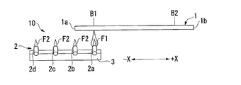
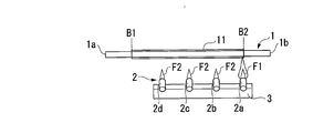
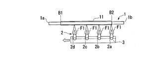
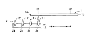
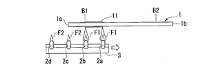
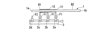
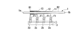
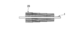
- FIG. 1A It is a figure which shows the process following FIG. 1A. It is a figure which shows the process of following FIG. 1B. It is a figure which shows the process of following FIG. 1C. It is a figure of the porous glass particulate body obtained by the manufacturing method concerning a 1st embodiment. It is a figure explaining the manufacturing method of the porous glass fine particle body which concerns on 2nd Embodiment. It is a figure which shows the process of following FIG. 3A. It is a figure which shows the process of following FIG. 3B. It is a figure which shows the process of following FIG. 3C. It is a figure which shows the process of following FIG. 3D. It is a figure which shows the process of following FIG. 3E. It is a figure of the porous glass fine particle obtained by the manufacturing method concerning a 2nd embodiment.
- the porous glass fine particles obtained according to the present embodiment can be applied to, for example, the OVD method (Outside Vapor Deposition method) or the VAD method (Vapor phase Axial Deposition method) to obtain an optical fiber preform.
- this invention is not limited to the following embodiment.
- the OVD method glass fine particles are deposited on the outer surface of a starting base material such as a glass rod to form a soot layer to obtain a porous glass fine particle body, and then the soot layer is sintered by heating to sinter the optical fiber mother.
- a starting base material such as a glass rod
- the soot layer is sintered by heating to sinter the optical fiber mother.
- the porous glass particulate material manufacturing apparatus 10 of the present embodiment includes a burner group 2 having a plurality of burners 2a to 2d, a fixing base 3, and a gas supply device (not shown). I have. The number of burners included in the burner group 2 may be changed as appropriate.
- the plurality of burners 2 a to 2 d are arranged side by side along the longitudinal direction X of the starting base material 1.
- the starting base material 1 is a glass rod made of quartz glass or the like. Both ends (first end 1a and second end 1b) of the starting base material 1 are supported by a pair of rotating chucks (not shown). The starting base material 1 is rotated in a reaction vessel (not shown) by the rotating chuck.
- the longitudinal direction of the starting base material 1 is simply referred to as the longitudinal direction X.
- the burner 2a side is referred to as + X side
- the burner 2d side is referred to as -X side. That is, burner 2a (first burner), burner 2b (second burner), burner 2c (third burner), and burner 2d (fourth burner) are arranged in this order from the + X side to the -X side. ing.
- the plurality of burners 2a to 2d are fixed to the fixed base 3, and are arranged at equal intervals in the longitudinal direction X.
- the fixed base 3 is movable in the longitudinal direction X along a rail (not shown). That is, the burner group 2 can move relative to the starting base material 1 along the longitudinal direction X of the starting base material 1.
- the burner group 2 moves so as to reciprocate in the longitudinal direction X.
- the starting base material 1 may be reciprocated along the longitudinal direction X while the burner group 2 is stationary. That is, the burner group 2 only needs to be able to reciprocate relative to the starting base material 1 along the longitudinal direction X.
- a gas supply device (not shown) is connected to each burner 2a to 2d.
- the gas supply device supplies the fuel, raw material gas, oxygen gas, etc. of the seed fire F2 to the burners 2a to 2d. It should be noted that the fuel supply device for the seed flame F2 and the material gas supply device may be different.
- the flame when the raw material gas is supplied to the burners 2a to 2d and the glass fine particles are generated is referred to as a generated flame F1.
- a flame in which no source gas is supplied to the burners 2a to 2d and no glass particles are generated is referred to as a seed flame F2.
- both the generated flame F1 and the seed flame F2 are included.
- the setting of the fire power of the flame may be different for each of the burners 2a to 2d, or may be common. The setting may be changed with the number of reciprocating motions of the burner group 2.
- the seed flame F2 is always generated even when the generated flame F1 is not generated. Thereby, when the raw material gas is supplied to the burners 2a to 2d, the generation of the glass fine particles can be started smoothly. However, before the source gas is supplied, the seed fire F2 may be extinguished and the seed fire F2 may be generated immediately before the source gas is supplied. Further, the thermal power of the seed fire F2 may be changed, for example, by weakening the thermal power of the seed fire F2 before supplying the raw material gas and increasing the thermal power of the seed fire F2 immediately before supplying the raw material gas.
- Burners 2a to 2d generate seed fire F2 using a mixed gas of combustible gas (for example, hydrogen gas or methane) and oxygen.
- a raw material gas is discharged into the seed flame F2 to generate a generated flame F1, and glass fine particles are generated by an oxidation reaction or a hydrolysis reaction.
- the glass fine particles are deposited (deposited) on the surface of the starting base material 1 to form a soot, whereby the porous glass fine particle body 20 is obtained.
- silicon tetrachloride SiCl 4
- a silicon-containing organic compound As the source gas, for example, silicon tetrachloride (SiCl 4 ) or a silicon-containing organic compound can be used.
- silicon-containing organic compound alkylsiloxanes such as cyclic siloxane D3 (hexamethylcyclotrisiloxane), D4 (octamethylcyclotetrasiloxane, OMCTS), D5 (decamethylcyclopentasiloxane) can be used.
- D in the above-mentioned silicon-containing organic compound means a unit of [(CH 3 ) 2 —Si] —O—, for example, D4 means a structure in which four D units are connected in a ring shape.
- the silicon-containing organic compound does not generate hydrochloric acid even when it is oxidized, it contributes to reducing the environmental burden and manufacturing cost by eliminating the need for hydrochloric acid treatment equipment.
- D4 is widely used industrially and is relatively inexpensive and easily available.
- the first layer forming step shown in FIGS. 1A to 1B is performed. More specifically, as shown in FIG. 1A, the raw material gas is supplied to the burner 2a in a state where the burner 2a is present at a predetermined first boundary position B1. Thereby, the production
- the burner group 2 (fixed base 3) is moved to the + X side with respect to the starting base material 1. Thereby, the glass fine particles produced
- the first soot layer 11 is a soot layer that is first deposited on the starting base material 1.
- the raw material gas is continuously supplied to the burner 2a until the burner 2a reaches the second boundary position B2 from the first boundary position B1 to generate glass particles.
- the 1st soot layer 11 is continuously formed in the longitudinal direction X without a cut
- the first soot layer 11 formed can be heated by generating the seed fire F2 in the burners 2b to 2d.
- the outer layer forming step shown in FIGS. 1C to 1D is performed.
- a plurality of soot layers 12 to 14 are formed outside the first soot layer 11.
- the number of soot layers formed in the outer layer forming step is, for example, about 50 to 1000, and the thickness per layer is, for example, about 0.01 to 1.0 mm. is there.
- the raw material gas is also supplied to the burners 2b to 2d to generate the generated flame F1 respectively.
- the burner group 2 is moved to the ⁇ X side with respect to the starting base material 1.
- the second soot layer 12 is formed.
- the glass particles generated by the respective burners 2a to 2d are separately deposited on the first soot layer 11.
- the second soot layer 12 is formed by being divided into regions 12a to 12d.
- the interface between areas is formed in the longitudinal direction X at intervals.
- the burner group 2 is reciprocated relative to the starting base material 1 in the longitudinal direction X between the first boundary position B1 and the second boundary position B2. Thereby, as shown in FIG. 2, the soot layer is sequentially deposited, and the porous glass fine particle body 20 is obtained.
- the porous glass fine particle body 20 is dehydrated (dehydration process) and sintered (sintering process).
- the sintering step may be after the dehydration step or at the same time as the dehydration step.
- the dehydration step moisture contained in the soot layer of the porous glass fine particle body 20 is removed using dehydrated gas. By removing the moisture, it is possible to reduce the transmission loss of light of the optical fiber obtained from the porous glass fine particle body 20.
- the dehydrating gas an inert gas containing a dehydrating agent can be used.
- the dehydrating agent chlorine (Cl 2 ), a chlorine compound such as thionyl chloride (SOCl 2 ), or the like can be used.
- the porous glass fine particle body 20 is placed in a dehydrated gas atmosphere and heated. At this time, dehydration gas enters the pores of the porous glass fine particle body 20, thereby dehydrating the porous glass fine particle body 20. For this reason, the smaller the density of the fine glass particles in the soot layer, the easier the dehydration gas enters, and the dehydration can be performed efficiently.
- the porous glass fine particle body 20 is heated at a high temperature (for example, 1400 ° C.) to vitrify the soot layer.
- a high temperature for example, 1400 ° C.
- the soot layer becomes a transparent glass body, and an optical fiber preform is obtained.
- an optical fiber can be manufactured by melting and drawing an optical fiber preform.
- defects such as interface shift, bubble mixing, and white turbidity may occur.
- the temperature at the time of forming the first soot layer 11 is increased and the first soot layer 11 is firmly attached to the starting base material 1.
- the density of the glass fine particles in the first soot layer 11 is increased.
- the density of the glass fine particles increases, it becomes difficult for the dehydrated gas to enter the pores in the dehydration step described above. As a result, the efficiency of the dehydration process may be reduced, or the dehydration may be insufficient.
- a decrease in the efficiency of the dehydration process leads to a decrease in the manufacturing efficiency and cost of the optical fiber preform and the optical fiber.
- Insufficient dehydration leads to an increase in transmission loss due to moisture in the optical fiber (for example, an increase in loss at a wavelength of 1383 nm).
- it is required to suppress the occurrence of defects at the boundary surface between the first soot layer 11 and the starting base material 1 without increasing the temperature at which the first soot layer 11 is formed.
- a first layer forming step for forming the first soot layer 11 on the surface of the starting base material 1, and a plurality of soot layers on the outside of the first soot layer 11 are provided. And an outer layer forming step to be formed.
- the first soot layer 11 is continuously formed in the longitudinal direction X without any breaks.
- the first soot layer 11 by forming the first soot layer 11 continuously without any breaks, it is possible to suppress the occurrence of defects such as an interface shift at the interface between the first soot layer 11 and the starting base material 1, bubble mixing, and white turbidity. be able to. And since the said effect is acquired, without making the temperature at the time of forming the 1st soot layer 11 high, the density of the glass fine particle body in the 1st soot layer 11 can be suppressed small, and a dehydration process is carried out efficiently. And it can be done more reliably.
- glass particles generated by each of the burners 2a to 2d are deposited while reciprocating the burner group 2 relative to the starting base material 1 in the longitudinal direction X. Thereby, the manufacturing efficiency of the porous glass fine particle body 20 can be improved.
- the first soot layer 11 can be suppressed from being lowered by heating the first soot layer 11 with the seed fire F2 of the burners 2b to 2d.
- the first soot layer 11 can be suppressed from being lowered by heating the first soot layer 11 with the seed fire F2 of the burners 2b to 2d.
- the temperature drop of the first soot layer 11 it is possible to suppress the occurrence of defects due to temperature unevenness (temperature distribution, temperature change, etc.) during the manufacturing. More specifically, when the temperature unevenness occurs, the first soot layer 11 and the starting base material 1 have different linear expansion coefficients, and thus cracks starting from the interface between the first soot layer 11 and the starting base material 1 occur.
- Cheap by heating the first soot layer 11 with the seed fire F2 of the burners 2b to 2d as described above, the temperature of the first soot layer 11 can be stabilized and the occurrence of cracks and the like can be suppressed.
- the outer layer forming step after the first layer forming step is completed, the supply of the raw material gas is started to the burners 2b to 2d different from the burner 2a on which the first soot layer 11 is formed.
- the diameter of the porous glass fine particle body 20 can be stabilized in the longitudinal direction X.
- the outer layer forming step is performed after the first layer forming step is completed. In contrast, in the present embodiment, the first layer forming step and the outer layer forming step are performed simultaneously.
- a raw material gas is supplied to the burner 2a in a state where the burner 2a is present at a predetermined first boundary position B1.
- generation flame F1 arises in the burner 2a, and the production
- the source gas is not supplied to the burners 2b to 2d, and the seed fire F2 is generated.
- the heating power of the seed fire F2 does not need to be constant and may be changed as appropriate.
- the seed fire F2 may be extinguished or weakened until the source gas is supplied to the burners 2b to 2d, and the seed fire F2 may be ignited or the heating power may be increased immediately before the source gas is supplied.
- the burner group 2 (fixed base 3) is moved to the + X side with respect to the starting base material 1. Thereby, the first soot layer 11 is formed. Then, when the burner 2b reaches the first boundary position B1, the raw material gas is supplied to the burner 2b. As a result, the generated flame F1 is generated in the burner 2b, the generation of the glass fine particles is started, and the second soot layer 12 is formed on the surface of the first soot layer 11.
- the raw material gases are supplied to the respective burners 2c and 2d. That is, in the present embodiment, the supply of the source gas to the reached burners 2a to 2d is started when the plurality of burners 2a to 2d reach the first boundary position B1. Therefore, the second to fourth soot layers 12 to 14 are formed at the same time as the first soot layer 11 is formed. That is, the first layer forming step and the outer layer forming step are performed simultaneously.
- the fixing base 3 starts to move back toward the ⁇ X side.
- the burner 2 a forms the second soot layer 12 on the first soot layer 11. That is, the second soot layer 12 is separately formed into a portion formed by the burner 2a and a portion formed by the burner 2b.
- the third to fourth soot layers 13 and 14 are separately formed in the longitudinal direction X by the burners 2a to 2d.
- the first soot layer 11 is continuously formed by the burner 2a without a break. Therefore, the effect by forming the 1st soot layer 11 continuously without a cut
- the supply of the source gas to the burners 2a to 2d is started when the first boundary position B1 is reached.
- the glass fine particles generated in an unstable state in the initial reaction of the raw material gas are porous. Accumulation in the intermediate portion in the longitudinal direction X of the glassy fine glass body 20 is suppressed. Therefore, it is possible to increase the ratio of the portion that can be used as a non-defective part in the porous glass fine particle body 20 to improve the yield.
- the structure of this embodiment is suitable when using a silicon-containing organic compound as source gas.
- the number of soot layers to be formed changes in the longitudinal direction X as shown in FIG.
- the thickness of one soot layer is about 0.01 to 1.0 mm
- the influence on the stability of the diameter of the porous glass fine particle body 20 is small.
- the amount of the glass fine particles generated by the burners 2a to 2d and deposited on the starting base material 1 may be changed so that the diameter of the porous glass fine particle body 20 is more stable in the longitudinal direction X.
- the amount of the glass fine particles deposited on the starting base material 1 can be adjusted according to various conditions such as the flow rate of the raw material gas, the moving speed of the burner group 2 with respect to the starting base material 1, and the airflow in the reaction vessel.
- the folding position in the reciprocating motion of the burner group 2 when forming the second and subsequent layers of soot is fixed, but the folding position may be gradually shifted. Thereby, it can suppress that the diameter of the porous glass particulate body 20 fluctuates in the longitudinal direction X.
- the boundary positions B1 and B2 when the first soot layer 11 is formed may be different from the boundary positions B1 and B2 when the outer soot layer is formed.
- the burners 2a to 2d are arranged at equal intervals. However, the burners 2a to 2d may not be arranged at equal intervals.
Landscapes
- Chemical & Material Sciences (AREA)
- Engineering & Computer Science (AREA)
- Chemical Kinetics & Catalysis (AREA)
- General Chemical & Material Sciences (AREA)
- Life Sciences & Earth Sciences (AREA)
- General Life Sciences & Earth Sciences (AREA)
- Geochemistry & Mineralogy (AREA)
- Manufacturing & Machinery (AREA)
- Materials Engineering (AREA)
- Organic Chemistry (AREA)
- Manufacture, Treatment Of Glass Fibers (AREA)
Abstract
多孔質ガラス微粒子体の製造方法は、出発母材の表面に第1スート層を形成する第1層形成工程と、第1スート層の外側に複数のスート層を形成する外層形成工程と、を有する。第1層形成工程では、長手方向で切れ目なく連続的に第1スート層を形成する。外層形成工程では、各バーナーに原料ガスを供給してスート層を形成しながら、バーナー群を出発母材に対して長手方向に往復運動させる。
Description
本発明は、多孔質ガラス微粒子体の製造方法および光ファイバ母材の製造方法に関する。
本願は、2018年6月12日に、日本に出願された特願2018-112188号に基づき優先権を主張し、その内容をここに援用する。
本願は、2018年6月12日に、日本に出願された特願2018-112188号に基づき優先権を主張し、その内容をここに援用する。
従来から、特許文献1に示されるように、ガラスロッドなどの出発母材にガラス微粒子を堆積させてスートを形成する、多孔質ガラス微粒子体の製造方法が知られている。この種の多孔質ガラス微粒子体を焼結させると、光ファイバなどを製造するための光ファイバ母材を得ることができる。
また、特許文献1の製造方法では、並べて配置された複数のバーナーを、出発母材に対して往復移動させている。そして、出発母材に対するガラス微粒子(スート)の堆積開始時からいくつかの層を堆積させるまでは、往復移動の折り返し位置を固定とし、その後は往復移動毎に折り返し位置を移動させている。この構成により、出発母材とスートとの界面に生じるずれを抑制することが開示されている。
また、特許文献1の製造方法では、並べて配置された複数のバーナーを、出発母材に対して往復移動させている。そして、出発母材に対するガラス微粒子(スート)の堆積開始時からいくつかの層を堆積させるまでは、往復移動の折り返し位置を固定とし、その後は往復移動毎に折り返し位置を移動させている。この構成により、出発母材とスートとの界面に生じるずれを抑制することが開示されている。
特許文献1の製造方法により得られる多孔質ガラス微粒子体では、スート層同士の長手方向における境界面と、出発母材とスート層との境界面と、が交差してしまう。このように、2つの境界面が交差すると、当該交差部で界面ずれ、白濁、気泡の混入などの不良が生じやすくなってしまう。
上記のような不良は、例えば単一のバーナーを往復運動させてスートを堆積させることで改善できるが、この場合にはスートの堆積に要する時間が増大して製造効率が低下してしまう。
上記のような不良は、例えば単一のバーナーを往復運動させてスートを堆積させることで改善できるが、この場合にはスートの堆積に要する時間が増大して製造効率が低下してしまう。
本発明はこのような事情を考慮してなされ、製造効率を維持しながら、スート層と出発母材との境界面における不良が発生することを抑制した多孔質ガラス微粒子体の製造方法を提供することを目的とする。
上記課題を解決するために、本発明の一態様に係る多孔質ガラス微粒子体の製造方法は、回転する出発母材の長手方向に沿ってバーナー群を前記出発母材に対して移動させ、前記バーナー群の火炎に原料ガスを放出することで前記出発母材の表面に複数のスート層を形成する多孔質ガラス微粒子体の製造方法であって、前記出発母材の表面に第1スート層を形成する第1層形成工程と、前記第1スート層の外側に複数のスート層を形成する外層形成工程と、を有し、前記第1層形成工程では、前記長手方向で切れ目なく連続的に前記第1スート層を形成し、前記外層形成工程では、前記バーナー群に含まれる各バーナーに原料ガスを供給してスート層を形成しながら、前記バーナー群を前記出発母材に対して前記長手方向に往復運動させる。
本発明の上記態様によれば、製造効率を維持しながら、スート層と出発母材との境界面における不良が発生することを抑制した多孔質ガラス微粒子体の製造方法を提供することができる。
(第1実施形態)
以下、第1実施形態の多孔質ガラス微粒子体の製造方法について図面に基づいて説明する。本実施形態により得られる多孔質ガラス微粒子体は、例えばOVD法(Outside Vapor Deposition method)またはVAD法(Vapor phase Axial Deposition method)などに適用することで、光ファイバ母材を得ることができる。なお、本発明は以下の実施形態に限定されない。
以下、第1実施形態の多孔質ガラス微粒子体の製造方法について図面に基づいて説明する。本実施形態により得られる多孔質ガラス微粒子体は、例えばOVD法(Outside Vapor Deposition method)またはVAD法(Vapor phase Axial Deposition method)などに適用することで、光ファイバ母材を得ることができる。なお、本発明は以下の実施形態に限定されない。
OVD法とは、ガラスロッド等の出発母材の外表面にガラス微粒子を堆積させてスート層を形成し、多孔質ガラス微粒子体を得た後、スート層を加熱により焼結して光ファイバ母材を得る方法である。
VAD法は、ガラスロッド等の出発母材の先端部からガラス微粒子の堆積を開始して、円柱状のスート層を形成し、多孔質ガラス微粒子体を得た後、スート層を加熱により焼結させることで、光ファイバ母材を得る方法である。
ただし、本実施形態により得られる多孔質ガラス微粒子体の用途は、光ファイバ母材の製造に限定されない。
VAD法は、ガラスロッド等の出発母材の先端部からガラス微粒子の堆積を開始して、円柱状のスート層を形成し、多孔質ガラス微粒子体を得た後、スート層を加熱により焼結させることで、光ファイバ母材を得る方法である。
ただし、本実施形態により得られる多孔質ガラス微粒子体の用途は、光ファイバ母材の製造に限定されない。
図1Aに示すように、本実施形態の多孔質ガラス微粒子体の製造装置10は、複数のバーナー2a~2dを有するバーナー群2と、固定台3と、ガス供給装置(不図示)と、を備えている。なお、バーナー群2に含まれるバーナーの数は適宜変更してもよい。
複数のバーナー2a~2dは、出発母材1の長手方向Xに沿って、並べて配置されている。出発母材1は、石英ガラス製のガラスロッドなどである。出発母材1の両端(第1端部1aおよび第2端部1b)は、一対の回転チャック(不図示)により支持されている。回転チャックにより、出発母材1は反応容器(不図示)内で回転させられる。
複数のバーナー2a~2dは、出発母材1の長手方向Xに沿って、並べて配置されている。出発母材1は、石英ガラス製のガラスロッドなどである。出発母材1の両端(第1端部1aおよび第2端部1b)は、一対の回転チャック(不図示)により支持されている。回転チャックにより、出発母材1は反応容器(不図示)内で回転させられる。
(方向定義)
本明細書では、出発母材1の長手方向を、単に長手方向Xという。長手方向Xに沿って、バーナー2a側を+X側といい、バーナー2d側を-X側という。すなわち、バーナー2a(第1バーナー)、バーナー2b(第2バーナー)、バーナー2c(第3バーナー)、およびバーナー2d(第4バーナー)は、+X側から-X側に向けて、この順に配置されている。
本明細書では、出発母材1の長手方向を、単に長手方向Xという。長手方向Xに沿って、バーナー2a側を+X側といい、バーナー2d側を-X側という。すなわち、バーナー2a(第1バーナー)、バーナー2b(第2バーナー)、バーナー2c(第3バーナー)、およびバーナー2d(第4バーナー)は、+X側から-X側に向けて、この順に配置されている。
複数のバーナー2a~2dは、固定台3に固定されており、長手方向Xに等間隔を空けて配置されている。固定台3は、不図示のレールに沿って、長手方向Xに移動可能となっている。すなわち、バーナー群2は、出発母材1の長手方向Xに沿って、出発母材1に対して相対移動可能である。
本実施形態では、バーナー群2が長手方向Xに往復するように移動する。ただし、バーナー群2を静止させたまま、出発母材1を長手方向Xに沿って往復させても良い。すなわち、バーナー群2は、長手方向Xに沿って出発母材1に対して相対往復運動することができればよい。
本実施形態では、バーナー群2が長手方向Xに往復するように移動する。ただし、バーナー群2を静止させたまま、出発母材1を長手方向Xに沿って往復させても良い。すなわち、バーナー群2は、長手方向Xに沿って出発母材1に対して相対往復運動することができればよい。
各バーナー2a~2dには、不図示のガス供給装置が接続されている。ガス供給装置は、バーナー2a~2dに、種火F2の燃料、原料ガス、酸素ガスなどを供給する。なお、種火F2の燃料の供給装置と原料ガスの供給装置とは別であってもよい。
ここで本明細書では、バーナー2a~2dに原料ガスが供給されて、ガラス微粒子を生成している際の火炎を生成火炎F1という。また、バーナー2a~2dに原料ガスが供給されておらず、ガラス微粒子を生成していない状態の火炎を種火F2という。また、単に「火炎」といった場合には、生成火炎F1および種火F2の両方を含むものとする。
なお、火炎(生成火炎F1また種火F2)の火力などの設定は、バーナー2a~2dごとに異なっていてもよいし、共通であってもよい。また当該設定を、バーナー群2の往復運動の回数に伴って変化させてもよい。
なお、火炎(生成火炎F1また種火F2)の火力などの設定は、バーナー2a~2dごとに異なっていてもよいし、共通であってもよい。また当該設定を、バーナー群2の往復運動の回数に伴って変化させてもよい。
本実施形態における多孔質ガラス微粒子体の製造方法では、生成火炎F1を生じさせていない間も、常時、種火F2を生じさせている。これにより、バーナー2a~2dに原料ガスが供給されたときに、スムーズにガラス微粒子の生成を開始することができる。ただし、原料ガスを供給する前は種火F2を消火しておき、原料ガスを供給する直前に種火F2を生じさせてもよい。また、原料ガスを供給する前は種火F2の火力を弱くしておき、原料ガスを供給する直前までに種火F2の火力を強くするなど、種火F2の火力を変化させてもよい。
バーナー2a~2dは、可燃性ガス(例えば、水素ガスやメタンなど)と酸素との混合ガス等で種火F2を生じさせる。その種火F2中に原料ガスを放出して生成火炎F1を生じさせ、酸化反応または加水分解反応によってガラス微粒子を生成する。このガラス微粒子が、出発母材1の表面に堆積(デポジション)してスートを形成することで、多孔質ガラス微粒子体20が得られる。
原料ガスとしては、例えば四塩化ケイ素(SiCl4)や、ケイ素含有有機化合物を用いることができる。ケイ素含有有機化合物としては、環状シロキサンD3(ヘキサメチルシクロトリシロキサン)、D4(オクタメチルシクロテトラシロキサン、OMCTS)、D5(デカメチルシクロペンタシロキサン)などのアルキルシロキサンを用いることができる。ここで、上記のケイ素含有有機化合物の「D」は、[(CH3)2-Si]-O-のユニットを意味し、例えばD4はDユニットが4つ環状につながった構造を意味する。ケイ素含有有機化合物は、酸化反応させても塩酸を発生させないため、環境負荷の低減や、塩酸の処理設備が不要となることによる製造コスト低減などに寄与する。特に、D4は工業的に広く用いられ、比較的安価で入手しやすい。
次に、多孔質ガラス微粒子体20の具体的な製造方法について説明する。
(第1層形成工程)
まず、図1A~図1Bに示す第1層形成工程を行う。より詳しくは、図1Aに示すように、所定の第1境界位置B1にバーナー2aがある状態で、バーナー2aに原料ガスを供給する。これにより、バーナー2aに生成火炎F1が生じ、ガラス微粒子の生成が開始される。このとき、バーナー2b~2dには原料ガスを供給せず、種火F2を生じさせておく。
まず、図1A~図1Bに示す第1層形成工程を行う。より詳しくは、図1Aに示すように、所定の第1境界位置B1にバーナー2aがある状態で、バーナー2aに原料ガスを供給する。これにより、バーナー2aに生成火炎F1が生じ、ガラス微粒子の生成が開始される。このとき、バーナー2b~2dには原料ガスを供給せず、種火F2を生じさせておく。
次に、図1Bに示すように、バーナー群2(固定台3)を出発母材1に対して+X側に移動させる。これにより、バーナー2aの生成火炎F1によって生成したガラス微粒子が出発母材1に堆積し、第1スート層11が形成される。第1スート層11とは、出発母材1に対して最初に堆積するスート層である。
第1層形成工程では、バーナー2aが第1境界位置B1から第2境界位置B2に到達するまで、連続的にバーナー2aに原料ガスを供給し、ガラス微粒子を生成する。これにより、第1スート層11は長手方向Xで切れ目なく連続的に形成される。
なお、第1層形成工程において、バーナー2b~2dに種火F2を生じさせておくことで、形成された第1スート層11を加熱することができる。
なお、第1層形成工程において、バーナー2b~2dに種火F2を生じさせておくことで、形成された第1スート層11を加熱することができる。
(外層形成工程)
第1層形成工程の後で、図1C~図1Dに示す外層形成工程を行う。外層形成工程では、第1スート層11の外側に複数のスート層12~14(図2参照)を形成する。なお、図2では簡略化して表示しているが、外層形成工程で形成するスート層の数は、例えば50~1000程度であり、1層あたりの厚みは例えば0.01~1.0mm程度である。
第1層形成工程の後で、図1C~図1Dに示す外層形成工程を行う。外層形成工程では、第1スート層11の外側に複数のスート層12~14(図2参照)を形成する。なお、図2では簡略化して表示しているが、外層形成工程で形成するスート層の数は、例えば50~1000程度であり、1層あたりの厚みは例えば0.01~1.0mm程度である。
外層形成工程では、まず図1Cに示すように、バーナー2b~2dにも原料ガスを供給して、それぞれに生成火炎F1を生じさせる。そして図1Dに示すように、バーナー群2を出発母材1に対して-X側に移動させる。これにより、第2スート層12が形成される。このとき、それぞれのバーナー2a~2dにより生成されたガラス微粒子が、第1スート層11上に別個に堆積する。このため、第2スート層12は領域12a~12dに分かれて形成される。そして第2スート層12には、領域同士の境界面が長手方向Xに間隔をあけて形成される。
以降は、第1境界位置B1と第2境界位置B2との間で、バーナー群2を出発母材1に対して長手方向Xに相対往復移動させる。これにより、図2に示すようにスート層が順次堆積し、多孔質ガラス微粒子体20が得られる。
(光ファイバ母材の製造方法)
光ファイバ母材を製造する場合には、多孔質ガラス微粒子体20を脱水し(脱水工程)、焼結させる(焼結工程)。焼結工程は、脱水工程の後であってもよいし、脱水工程と同時であってもよい。
光ファイバ母材を製造する場合には、多孔質ガラス微粒子体20を脱水し(脱水工程)、焼結させる(焼結工程)。焼結工程は、脱水工程の後であってもよいし、脱水工程と同時であってもよい。
脱水工程では、脱水ガスを用いて、多孔質ガラス微粒子体20のスート層に含まれる水分を除去する。水分を除去することで、多孔質ガラス微粒子体20から得られた光ファイバの光の伝送損失を低減することができる。脱水ガスとしては、脱水剤を含む不活性ガスを用いることができる。脱水剤としては、塩素(Cl2)や、塩化チオニル(SOCl2)などの塩素化合物などを用いることができる。なお、一酸化炭素など、塩素化合物以外の脱水剤を用いてもよい。
脱水工程では、例えば脱水ガスの雰囲気下に多孔質ガラス微粒子体20を設置して加熱する。このとき、多孔質ガラス微粒子体20が有する細孔に脱水ガスが進入することで、多孔質ガラス微粒子体20の内部まで脱水を行う。このため、スート層におけるガラス微粒子体の密度が小さいほうが、脱水ガスが進入しやすくなり、効率よく脱水を行うことができる。
焼結工程では、高温(例えば1400℃)で多孔質ガラス微粒子体20を加熱して、スート層をガラス化させる。これによりスート層が透明なガラス体となり、光ファイバ母材が得られる。
また、光ファイバ母材を溶融させて線引きすることで、光ファイバを製造することができる。
また、光ファイバ母材を溶融させて線引きすることで、光ファイバを製造することができる。
ところで、出発母材1と第1スート層11との境界面では、界面ずれ、気泡の混入、白濁などの不良が発生する場合がある。これらの不良の発生を抑制するためには、例えば第1スート層11を形成する際の温度を高くして、第1スート層11を出発母材1に対して強固に付着させることが考えられる。しかしながら、第1スート層11を形成する際の温度を高くすると、第1スート層11におけるガラス微粒子体の密度が大きくなってしまう。そして、ガラス微粒子体の密度が大きくなると、上記した脱水工程において、細孔に脱水ガスが進入しにくくなる。結果として、脱水工程の効率が低下したり、脱水が不十分となったりする可能性がある。
脱水工程の効率の低下は、光ファイバ母材および光ファイバの製造効率の低下、コストの増大につながる。また、脱水が不十分であると、光ファイバにおける水分による伝送損失の増大(例えば、波長1383nmにおけるロス増)につながる。
このような事情から、第1スート層11を形成する際の温度を高くせずに、第1スート層11と出発母材1との境界面における不良の発生を抑えることが求められている。
このような事情から、第1スート層11を形成する際の温度を高くせずに、第1スート層11と出発母材1との境界面における不良の発生を抑えることが求められている。
そこで本実施形態の多孔質ガラス微粒子体の製造方法は、出発母材1の表面に第1スート層11を形成する第1層形成工程と、第1スート層11の外側に複数のスート層を形成する外層形成工程と、を有している。そして第1層形成工程では、長手方向Xで切れ目なく連続的に第1スート層11を形成する。
このように、第1スート層11を切れ目なく連続的に形成することで、第1スート層11と出発母材1との界面における界面ずれ、気泡の混入、白濁などの不良の発生を抑制することができる。そして、第1スート層11を形成する際の温度を高くせずに上記効果が得られるため、第1スート層11におけるガラス微粒子体の密度を小さく抑えることができ、脱水工程を効率的に、そしてより確実に行うことができる。そのうえで、外層形成工程では、バーナー群2を出発母材1に対して長手方向Xに相対的に往復運動させながら、各バーナー2a~2dで生成されたガラス微粒子を堆積させる。これにより、多孔質ガラス微粒子体20の製造効率を高めることができる。
また、第1層形成工程において、バーナー2b~2dの種火F2により第1スート層11を加熱することで、第1スート層11の温度低下を抑えることができる。このように、第1スート層11の温度低下を抑えることで、製造途中における温度ムラ(温度分布や温度変化など)に起因する不良の発生を抑制することができる。より詳しくは、温度ムラが生じると、第1スート層11と出発母材1とで線膨張係数が異なるため、第1スート層11と出発母材1との界面を起点とするひび割れなどが生じやすい。これに対して、上記の通りバーナー2b~2dの種火F2で第1スート層11を加熱することで、第1スート層11の温度を安定させて、ひび割れなどの発生を抑えることができる。
また、外層形成工程では、第1層形成工程が完了した後、第1スート層11を形成したバーナー2aとは異なるバーナー2b~2dに原料ガスの供給を開始している。この構成により、長手方向Xで多孔質ガラス微粒子体20の直径を安定させることができる。
(第2実施形態)
次に、本発明に係る第2実施形態について説明するが、第1実施形態と基本的な構成は同様である。このため、同様の構成には同一の符号を付してその説明は省略し、異なる点についてのみ説明する。
第1実施形態では、第1層形成工程が完了した後で、外層形成工程を行った。これに対して本実施形態では、第1層形成工程および外層形成工程を同時に行う。
次に、本発明に係る第2実施形態について説明するが、第1実施形態と基本的な構成は同様である。このため、同様の構成には同一の符号を付してその説明は省略し、異なる点についてのみ説明する。
第1実施形態では、第1層形成工程が完了した後で、外層形成工程を行った。これに対して本実施形態では、第1層形成工程および外層形成工程を同時に行う。
まず、図3Aに示すように、所定の第1境界位置B1にバーナー2aがある状態で、バーナー2aに原料ガスを供給する。これにより、バーナー2aに生成火炎F1が生じ、ガラス微粒子の生成が開始される。このとき、バーナー2b~2dには原料ガスを供給せず、種火F2を生じさせておく。なお、種火F2の火力は一定である必要はなく、適宜変化させてもよい。また、バーナー2b~2dに原料ガスを供給するまでは種火F2を消火あるいは弱火にしておき、原料ガスを供給する直前に種火F2を点火させたり火力を強くしたりしてもよい。
次に、図3B~図3Cに示すように、バーナー群2(固定台3)を出発母材1に対して+X側に移動させる。これにより、第1スート層11が形成される。そして、バーナー2bが第1境界位置B1に到達した時点で、バーナー2bに原料ガスを供給する。これにより、バーナー2bに生成火炎F1が生じ、ガラス微粒子の生成が開始され、第1スート層11の表面に第2スート層12が形成される。
以降も同様に、図3C~図3Dに示すように、バーナー2c、2dが第1境界位置B1に到達した時点で、それぞれのバーナー2c、2dに原料ガスを供給する。つまり本実施形態では、複数のバーナー2a~2dが第1境界位置B1に到達した時点で、到達したバーナー2a~2dに対する原料ガスの供給を開始する。このため、第1スート層11を形成しつつ、第2~第4スート層12~14も同時に形成されることとなる。すなわち、第1層形成工程および外層形成工程が同時に行われる。
図3E~図3Fに示すように、バーナー2aが所定の第2境界位置B2に到達すると、固定台3は-X側に向けて折り返し移動を開始する。このとき、バーナー2aは第1スート層11の上に、第2スート層12を形成する。つまり、第2スート層12は、バーナー2aによって形成された部分と、バーナー2bによって形成された部分とに、分かれて形成されることとなる。
第3~第4スート層13、14についても同様に、各バーナー2a~2dによって長手方向Xに分かれて形成される。
第3~第4スート層13、14についても同様に、各バーナー2a~2dによって長手方向Xに分かれて形成される。
一方、第1スート層11については、バーナー2aによって切れ目なく連続的に形成される。したがって、第1実施形態と同様に、第1スート層11を切れ目なく連続的に形成することによる作用効果を得ることができる。
また、本実施形態では、第1層形成工程を行っている間に、第1スート層11を形成するバーナー2aとは異なるバーナー2b~2dに生成火炎F1を生じさせることで、第1スート層11を加熱している。したがって、第1実施形態と同様に、第1スート層11の温度低下を抑えて、温度ムラに起因する不良の発生を抑制することができる。
また、本実施形態では、第1層形成工程を行っている間に、第1スート層11を形成するバーナー2aとは異なるバーナー2b~2dに生成火炎F1を生じさせることで、第1スート層11を加熱している。したがって、第1実施形態と同様に、第1スート層11の温度低下を抑えて、温度ムラに起因する不良の発生を抑制することができる。
また、本実施形態では、第1境界位置B1に到達した時点でバーナー2a~2dに原料ガスの供給を開始している。このため、例えば境界位置B1、B2の間にバーナー2a~2dが位置するときに供給を開始する場合と比較して、原料ガスの反応初期における不安定な状態で生成されたガラス微粒子が、多孔質ガラス微粒子体20の長手方向Xにおける中間部に堆積することが抑えられる。したがって、多孔質ガラス微粒子体20のうち、良品部として使用可能な部分の割合を大きくして、歩留まりを向上させることができる。
特に、原料ガスとしてケイ素含有有機化合物を用いた場合には、原料ガスと酸素ガスとの混合比率が不安定であることによる不良が生じやすい。そして、原料ガスの供給開始当初では、酸素ガスと原料ガスとの混合比率が安定しにくいため、上記した不良が生じやすい。したがって、本実施形態の構成は、原料ガスとしてケイ素含有有機化合物を用いる場合に好適である。
なお、本実施形態の製造方法によって得られる多孔質ガラス微粒子体20は、図4に示すように、形成されるスート層の数が長手方向Xで変化することとなる。しかしながら、1つのスート層の厚みは0.01~1.0mm程度であるので、多孔質ガラス微粒子体20の直径の安定性に与える影響は小さい。
また、例えば多孔質ガラス微粒子体20の直径が長手方向Xでより安定するように、各バーナー2a~2dによって生成されて出発母材1に堆積するガラス微粒子の量を変化させてもよい。出発母材1に堆積するガラス微粒子の量は、原料ガスの流量、バーナー群2の出発母材1に対する移動速度、反応容器内の気流など、種々の条件によって調整することができる。
また、例えば多孔質ガラス微粒子体20の直径が長手方向Xでより安定するように、各バーナー2a~2dによって生成されて出発母材1に堆積するガラス微粒子の量を変化させてもよい。出発母材1に堆積するガラス微粒子の量は、原料ガスの流量、バーナー群2の出発母材1に対する移動速度、反応容器内の気流など、種々の条件によって調整することができる。
なお、本発明の技術的範囲は前記実施の形態に限定されず、本発明の趣旨を逸脱しない範囲において種々の変更を加えることが可能である。
例えば、前記実施形態では、2層目以降のスートを形成する際のバーナー群2の往復運動における折り返し位置を固定していたが、折り返し位置を徐々にずらしてもよい。これにより、多孔質ガラス微粒子体20の直径が長手方向Xで変動することを抑えることができる。
また、第1スート層11を形成する際の境界位置B1、B2と、外側のスート層を形成する際の境界位置B1、B2とは異なっていてもよい。
また、前記実施形態ではバーナー2a~2dが等間隔に配置されていたが、バーナー2a~2d同士の間は等間隔でなくてもよい。
また、前記実施形態ではバーナー2a~2dが等間隔に配置されていたが、バーナー2a~2d同士の間は等間隔でなくてもよい。
その他、本発明の趣旨を逸脱しない範囲で、上記した実施の形態における構成要素を周知の構成要素に置き換えることは適宜可能であり、また、上記した実施形態や変形例を適宜組み合わせてもよい。
1…出発母材 2…バーナー群 2a~2d…バーナー 11…第1スート層 12~14…外側スート層 B1…第1境界位置(境界位置) X…長手方向
Claims (5)
- 回転する出発母材の長手方向に沿ってバーナー群を前記出発母材に対して移動させ、前記バーナー群の火炎に原料ガスを放出することで前記出発母材の表面に複数のスート層を形成する多孔質ガラス微粒子体の製造方法であって、
前記出発母材の表面に第1スート層を形成する第1層形成工程と、
前記第1スート層の外側に複数のスート層を形成する外層形成工程と、を有し、
前記第1層形成工程では、前記長手方向で切れ目なく連続的に前記第1スート層を形成し、
前記外層形成工程では、前記バーナー群に含まれる各バーナーに原料ガスを供給してスート層を形成しながら、前記バーナー群を前記出発母材に対して前記長手方向に往復運動させる、多孔質ガラス微粒子体の製造方法。 - 前記第1層形成工程では、前記第1スート層を形成するバーナーとは異なるバーナーから火炎を生じさせることによって前記第1スート層を加熱する、請求項1に記載の多孔質ガラス微粒子体の製造方法。
- 前記外層形成工程では、前記第1層形成工程が完了した後、前記第1スート層を形成したバーナーとは異なるバーナーに原料ガスの供給を開始する、請求項1または2に記載の多孔質ガラス微粒子体の製造方法。
- 前記外層形成工程では、前記第1層形成工程を行っている間に、前記バーナー群に含まれるバーナーが、前記長手方向における所定の境界位置に到達したときに、当該バーナーに原料ガスの供給を開始する、請求項1または2に記載の多孔質ガラス微粒子体の製造方法。
- 請求項1から4のいずれか1項に記載の方法により得られた多孔質ガラス微粒子体に含まれる水分を除去する脱水工程を有する、光ファイバ母材の製造方法。
Priority Applications (2)
| Application Number | Priority Date | Filing Date | Title |
|---|---|---|---|
| US17/053,169 US11780761B2 (en) | 2018-06-12 | 2019-04-12 | Method for producing porous glass fine particle body and method for producing optical fiber preform |
| CN201980034573.7A CN112188999B (zh) | 2018-06-12 | 2019-04-12 | 多孔质玻璃微粒子体的制造方法以及光纤母材的制造方法 |
Applications Claiming Priority (2)
| Application Number | Priority Date | Filing Date | Title |
|---|---|---|---|
| JP2018-112188 | 2018-06-12 | ||
| JP2018112188A JP6694915B2 (ja) | 2018-06-12 | 2018-06-12 | 多孔質ガラス微粒子体の製造方法および光ファイバ母材の製造方法 |
Publications (1)
| Publication Number | Publication Date |
|---|---|
| WO2019239705A1 true WO2019239705A1 (ja) | 2019-12-19 |
Family
ID=68843150
Family Applications (1)
| Application Number | Title | Priority Date | Filing Date |
|---|---|---|---|
| PCT/JP2019/016024 Ceased WO2019239705A1 (ja) | 2018-06-12 | 2019-04-12 | 多孔質ガラス微粒子体の製造方法および光ファイバ母材の製造方法 |
Country Status (4)
| Country | Link |
|---|---|
| US (1) | US11780761B2 (ja) |
| JP (1) | JP6694915B2 (ja) |
| CN (1) | CN112188999B (ja) |
| WO (1) | WO2019239705A1 (ja) |
Families Citing this family (1)
| Publication number | Priority date | Publication date | Assignee | Title |
|---|---|---|---|---|
| JP7399835B2 (ja) * | 2020-10-07 | 2023-12-18 | 信越化学工業株式会社 | 光ファイバ用多孔質ガラス堆積体の製造方法 |
Citations (3)
| Publication number | Priority date | Publication date | Assignee | Title |
|---|---|---|---|---|
| JPS63310745A (ja) * | 1987-06-15 | 1988-12-19 | Fujikura Ltd | ガラス母材の製造装置 |
| JP2006248880A (ja) * | 2005-03-14 | 2006-09-21 | Furukawa Electric Co Ltd:The | 光ファイバ母材の製造方法 |
| KR20140065292A (ko) * | 2012-11-21 | 2014-05-29 | 삼성전자주식회사 | 광섬유 모재의 제조 장치 |
Family Cites Families (20)
| Publication number | Priority date | Publication date | Assignee | Title |
|---|---|---|---|---|
| JP2612949B2 (ja) | 1990-02-01 | 1997-05-21 | 信越化学工業株式会社 | 光ファイバプリフォーム母材の製造方法 |
| US5211732A (en) * | 1990-09-20 | 1993-05-18 | Corning Incorporated | Method for forming a porous glass preform |
| JPH10120430A (ja) | 1996-10-22 | 1998-05-12 | Fujikura Ltd | 光ファイバ母材の製造方法 |
| JP3131162B2 (ja) * | 1996-11-27 | 2001-01-31 | 信越化学工業株式会社 | 光ファイバプリフォームの製造方法 |
| JP2001335339A (ja) | 2000-05-24 | 2001-12-04 | Sumitomo Electric Ind Ltd | 光ファイバ母材の製造方法 |
| AU1847502A (en) * | 2000-11-24 | 2002-06-03 | Sumitomo Electric Industries, Ltd. | Method and device for manufacturing glass particulate sedimented body |
| ES2364453T3 (es) * | 2001-04-27 | 2011-09-02 | Prysmian S.P.A. | Procedimiento para producir una preforma de fibra óptica. |
| EP1279646B1 (en) | 2001-07-26 | 2006-12-13 | Sumitomo Electric Industries, Ltd. | Method and apparatus for producing a glass preform for optical fibres |
| US20050092030A1 (en) * | 2003-10-31 | 2005-05-05 | Jitendra Balakrishnan | Method and apparatus for depositing glass soot |
| JP2005162541A (ja) | 2003-12-03 | 2005-06-23 | Sumitomo Electric Ind Ltd | ガラス母材の製造方法 |
| JP4423068B2 (ja) | 2004-03-03 | 2010-03-03 | 信越化学工業株式会社 | 光ファイバ用多孔質母材の製造方法及びガラス母材 |
| JP2006348880A (ja) | 2005-06-17 | 2006-12-28 | Aisin Seiki Co Ltd | 流体ポンプ |
| CN102741183B (zh) * | 2010-03-03 | 2016-02-03 | 株式会社藤仓 | 石英多孔质体的制造方法、光纤母材的制造方法、石英多孔质体及光纤母材 |
| WO2011136324A1 (ja) * | 2010-04-30 | 2011-11-03 | 住友電気工業株式会社 | ガラス母材製造方法 |
| JP5658912B2 (ja) * | 2010-05-27 | 2015-01-28 | 株式会社フジクラ | 光ファイバ母材の製造装置及び製造方法 |
| CN103842303B (zh) | 2011-09-29 | 2018-07-03 | 住友电气工业株式会社 | 玻璃微粒沉积体以及玻璃预制件的制造方法 |
| DE102012007520B3 (de) * | 2012-04-17 | 2013-08-08 | Heraeus Quarzglas Gmbh & Co. Kg | Verfahren für die Herstellung eines zylinderförmigen Bauteils aus Fluor enthaltendem synthetischem Quarzglas |
| JP6387739B2 (ja) | 2014-08-21 | 2018-09-12 | 住友電気工業株式会社 | ガラス微粒子堆積体の製造方法 |
| US10464838B2 (en) | 2015-01-13 | 2019-11-05 | Asi/Silica Machinery, Llc | Enhanced particle deposition system and method |
| CN111051259A (zh) * | 2017-08-29 | 2020-04-21 | 住友电气工业株式会社 | 玻璃微粒沉积体的制造方法、玻璃母材的制造方法以及玻璃母材 |
-
2018
- 2018-06-12 JP JP2018112188A patent/JP6694915B2/ja active Active
-
2019
- 2019-04-12 WO PCT/JP2019/016024 patent/WO2019239705A1/ja not_active Ceased
- 2019-04-12 CN CN201980034573.7A patent/CN112188999B/zh active Active
- 2019-04-12 US US17/053,169 patent/US11780761B2/en active Active
Patent Citations (3)
| Publication number | Priority date | Publication date | Assignee | Title |
|---|---|---|---|---|
| JPS63310745A (ja) * | 1987-06-15 | 1988-12-19 | Fujikura Ltd | ガラス母材の製造装置 |
| JP2006248880A (ja) * | 2005-03-14 | 2006-09-21 | Furukawa Electric Co Ltd:The | 光ファイバ母材の製造方法 |
| KR20140065292A (ko) * | 2012-11-21 | 2014-05-29 | 삼성전자주식회사 | 광섬유 모재의 제조 장치 |
Also Published As
| Publication number | Publication date |
|---|---|
| JP2019214489A (ja) | 2019-12-19 |
| CN112188999A (zh) | 2021-01-05 |
| US20210163337A1 (en) | 2021-06-03 |
| US11780761B2 (en) | 2023-10-10 |
| JP6694915B2 (ja) | 2020-05-20 |
| CN112188999B (zh) | 2022-09-13 |
Similar Documents
| Publication | Publication Date | Title |
|---|---|---|
| JP6058693B2 (ja) | 合成石英ガラスを製造する方法及び光ファイバーのクラッド材としての石英ガラス | |
| WO2013021759A1 (ja) | 光ファイバ母材および光ファイバの製造方法 | |
| CN107001108A (zh) | 具有单步氟凹槽与外包覆的光纤预成形件的制造方法 | |
| CN111615499B (zh) | 光纤母材的制造方法、光纤母材以及光纤的制造方法、光纤 | |
| CN108349780A (zh) | 光纤用玻璃母材的制造方法 | |
| US11780761B2 (en) | Method for producing porous glass fine particle body and method for producing optical fiber preform | |
| JP5163416B2 (ja) | 多孔質ガラス母材の製造方法 | |
| JP4124198B2 (ja) | 脱水及び脱塩素工程を含むmcvd法を用いた光ファイバ母材の製造方法及びこの方法により製造された光ファイバ | |
| JP2003261336A (ja) | 透明ガラス母材の製造方法 | |
| JP3579919B2 (ja) | 光ファイバ用母材の製造方法 | |
| JPH10203842A (ja) | 光ファイバ母材製造方法 | |
| JP2009114045A (ja) | 光ファイバ用ガラス母材の製造方法 | |
| JP2014101236A (ja) | 光ファイバ母材の製造方法および光ファイバ | |
| CN1596226A (zh) | 使用外部气相沉积法制造光纤预制棒的方法和设备 | |
| CN111032587B (zh) | 玻璃微粒沉积体的制造方法、玻璃母材的制造方法以及玻璃微粒沉积体 | |
| JP4472308B2 (ja) | 石英多孔質母材の製造方法 | |
| JP2007063095A (ja) | ガラス体製造方法及び光ファイバ | |
| JP2014201475A (ja) | 光ファイバ母材の製造方法及び製造装置 | |
| JP2005298271A (ja) | 光ファイバの製造方法及び光ファイバ | |
| JP2017043512A (ja) | 光ファイバ母材の製造方法、光ファイバの製造方法およびレンズの製造方法 | |
| JP2005089241A (ja) | 光ファイバ母材及び光ファイバ、並びに光ファイバの製造方法及び光ファイバ母材の製造方法 | |
| JP2025116588A (ja) | 光ファイバ母材および光ファイバ母材の製造方法 | |
| JP2005298287A (ja) | ガラス母材の製造方法 | |
| JP4140839B2 (ja) | 光ファイバ母材の製造方法 | |
| CN116209642A (zh) | 光纤母材的制造方法以及制造设备 |
Legal Events
| Date | Code | Title | Description |
|---|---|---|---|
| 121 | Ep: the epo has been informed by wipo that ep was designated in this application |
Ref document number: 19820023 Country of ref document: EP Kind code of ref document: A1 |
|
| NENP | Non-entry into the national phase |
Ref country code: DE |
|
| 122 | Ep: pct application non-entry in european phase |
Ref document number: 19820023 Country of ref document: EP Kind code of ref document: A1 |