WO2019225579A1 - 車両制御装置 - Google Patents
車両制御装置 Download PDFInfo
- Publication number
- WO2019225579A1 WO2019225579A1 PCT/JP2019/020045 JP2019020045W WO2019225579A1 WO 2019225579 A1 WO2019225579 A1 WO 2019225579A1 JP 2019020045 W JP2019020045 W JP 2019020045W WO 2019225579 A1 WO2019225579 A1 WO 2019225579A1
- Authority
- WO
- WIPO (PCT)
- Prior art keywords
- intersection
- host vehicle
- vehicle
- standby position
- road
- Prior art date
- Legal status (The legal status is an assumption and is not a legal conclusion. Google has not performed a legal analysis and makes no representation as to the accuracy of the status listed.)
- Ceased
Links
Images


Classifications
-
- B—PERFORMING OPERATIONS; TRANSPORTING
- B60—VEHICLES IN GENERAL
- B60W—CONJOINT CONTROL OF VEHICLE SUB-UNITS OF DIFFERENT TYPE OR DIFFERENT FUNCTION; CONTROL SYSTEMS SPECIALLY ADAPTED FOR HYBRID VEHICLES; ROAD VEHICLE DRIVE CONTROL SYSTEMS FOR PURPOSES NOT RELATED TO THE CONTROL OF A PARTICULAR SUB-UNIT
- B60W30/00—Purposes of road vehicle drive control systems not related to the control of a particular sub-unit, e.g. of systems using conjoint control of vehicle sub-units
- B60W30/18—Propelling the vehicle
- B60W30/18009—Propelling the vehicle related to particular drive situations
- B60W30/18154—Approaching an intersection
-
- B—PERFORMING OPERATIONS; TRANSPORTING
- B60—VEHICLES IN GENERAL
- B60W—CONJOINT CONTROL OF VEHICLE SUB-UNITS OF DIFFERENT TYPE OR DIFFERENT FUNCTION; CONTROL SYSTEMS SPECIALLY ADAPTED FOR HYBRID VEHICLES; ROAD VEHICLE DRIVE CONTROL SYSTEMS FOR PURPOSES NOT RELATED TO THE CONTROL OF A PARTICULAR SUB-UNIT
- B60W30/00—Purposes of road vehicle drive control systems not related to the control of a particular sub-unit, e.g. of systems using conjoint control of vehicle sub-units
- B60W30/18—Propelling the vehicle
- B60W30/18009—Propelling the vehicle related to particular drive situations
- B60W30/181—Preparing for stopping
-
- B—PERFORMING OPERATIONS; TRANSPORTING
- B60—VEHICLES IN GENERAL
- B60W—CONJOINT CONTROL OF VEHICLE SUB-UNITS OF DIFFERENT TYPE OR DIFFERENT FUNCTION; CONTROL SYSTEMS SPECIALLY ADAPTED FOR HYBRID VEHICLES; ROAD VEHICLE DRIVE CONTROL SYSTEMS FOR PURPOSES NOT RELATED TO THE CONTROL OF A PARTICULAR SUB-UNIT
- B60W30/00—Purposes of road vehicle drive control systems not related to the control of a particular sub-unit, e.g. of systems using conjoint control of vehicle sub-units
- B60W30/18—Propelling the vehicle
- B60W30/18009—Propelling the vehicle related to particular drive situations
- B60W30/18159—Traversing an intersection
-
- B—PERFORMING OPERATIONS; TRANSPORTING
- B60—VEHICLES IN GENERAL
- B60W—CONJOINT CONTROL OF VEHICLE SUB-UNITS OF DIFFERENT TYPE OR DIFFERENT FUNCTION; CONTROL SYSTEMS SPECIALLY ADAPTED FOR HYBRID VEHICLES; ROAD VEHICLE DRIVE CONTROL SYSTEMS FOR PURPOSES NOT RELATED TO THE CONTROL OF A PARTICULAR SUB-UNIT
- B60W60/00—Drive control systems specially adapted for autonomous road vehicles
- B60W60/001—Planning or execution of driving tasks
- B60W60/0011—Planning or execution of driving tasks involving control alternatives for a single driving scenario, e.g. planning several paths to avoid obstacles
-
- G—PHYSICS
- G01—MEASURING; TESTING
- G01C—MEASURING DISTANCES, LEVELS OR BEARINGS; SURVEYING; NAVIGATION; GYROSCOPIC INSTRUMENTS; PHOTOGRAMMETRY OR VIDEOGRAMMETRY
- G01C21/00—Navigation; Navigational instruments not provided for in groups G01C1/00 - G01C19/00
- G01C21/26—Navigation; Navigational instruments not provided for in groups G01C1/00 - G01C19/00 specially adapted for navigation in a road network
-
- G—PHYSICS
- G08—SIGNALLING
- G08G—TRAFFIC CONTROL SYSTEMS
- G08G1/00—Traffic control systems for road vehicles
- G08G1/16—Anti-collision systems
-
- B—PERFORMING OPERATIONS; TRANSPORTING
- B60—VEHICLES IN GENERAL
- B60W—CONJOINT CONTROL OF VEHICLE SUB-UNITS OF DIFFERENT TYPE OR DIFFERENT FUNCTION; CONTROL SYSTEMS SPECIALLY ADAPTED FOR HYBRID VEHICLES; ROAD VEHICLE DRIVE CONTROL SYSTEMS FOR PURPOSES NOT RELATED TO THE CONTROL OF A PARTICULAR SUB-UNIT
- B60W2552/00—Input parameters relating to infrastructure
- B60W2552/53—Road markings, e.g. lane marker or crosswalk
-
- B—PERFORMING OPERATIONS; TRANSPORTING
- B60—VEHICLES IN GENERAL
- B60W—CONJOINT CONTROL OF VEHICLE SUB-UNITS OF DIFFERENT TYPE OR DIFFERENT FUNCTION; CONTROL SYSTEMS SPECIALLY ADAPTED FOR HYBRID VEHICLES; ROAD VEHICLE DRIVE CONTROL SYSTEMS FOR PURPOSES NOT RELATED TO THE CONTROL OF A PARTICULAR SUB-UNIT
- B60W2555/00—Input parameters relating to exterior conditions, not covered by groups B60W2552/00, B60W2554/00
- B60W2555/60—Traffic rules, e.g. speed limits or right of way
Definitions
- the present disclosure relates to a vehicle control device that controls a vehicle.
- Japanese Patent Application Laid-Open No. 2004-133867 discloses a technique for waiting a host vehicle at a position where a blind spot due to a right turn vehicle in an opposite lane can be reduced when the host vehicle waits for a right turn at an intersection of a left-side traveling road.
- Patent Document 1 does not consider the case where the host vehicle cannot turn right before the traffic light turns red due to traffic congestion on the right turn destination road. For this reason, there is a possibility that the traveling of the vehicle on the intersecting green light road may be hindered by the red light while the host vehicle is waiting for a right turn in the intersection. Such a problem is not limited to the case where the host vehicle makes a right turn, but is a common problem when performing an operation accompanied by movement of the host vehicle at the intersection, such as when going straight through an intersection or when making a U-turn. Therefore, there has been a demand for a technique that can prevent the vehicle from traveling on the intersecting road.
- a vehicle control device is provided.
- the vehicle control device is a vehicle control device that is mounted on a host vehicle and controls the host vehicle, and is an intersection information detection unit that detects information of an intersection on which the host vehicle travels, and the vehicle control device
- An intersection information detection unit having a travel route detection unit that detects a route, and an intersection road detection unit (22) that detects an intersection road that intersects the travel route, and an operation involving movement of the host vehicle at the intersection
- the standby position setting unit sets a standby position for waiting the own vehicle at the intersection until the situation in which the own vehicle can execute the operation, and traveling of other vehicles traveling on the intersection road
- the standby position setting unit sets a standby position for waiting the own vehicle at the intersection until the situation in which the own vehicle can execute the operation, and traveling of other vehicles traveling on the intersection road
- the present disclosure can be realized in various forms.
- the present invention can be realized in the form of a vehicle including a vehicle control device, a vehicle control method, a computer program for realizing these devices and methods, and the like.
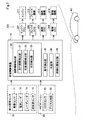
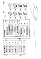
- FIG. 1 is a block diagram showing a schematic configuration of a vehicle control device
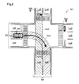
- FIG. 2 is an explanatory diagram for explaining a travel route and an intersection road
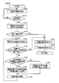
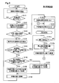
- FIG. 3 is a flowchart showing a procedure of vehicle control processing in the first embodiment.
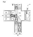
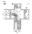
- FIG. 4 is an explanatory diagram for explaining the overlapping position and the standby position
- FIG. 5 is an explanatory diagram showing a state in which the traffic light on the traveling route of the host vehicle has turned red.
- FIG. 6 is an explanatory diagram showing a state in which the traffic light of the traveling route of the host vehicle becomes a red signal in the comparative example
- FIG. 1 is a block diagram showing a schematic configuration of a vehicle control device
- FIG. 2 is an explanatory diagram for explaining a travel route and an intersection road
- FIG. 3 is a flowchart showing a procedure of vehicle control processing in the first embodiment.
- FIG. 4 is an explanatory diagram for explaining the overlapping position and the standby position
- FIG. 5 is an explanatory
- FIG. 7 is a block diagram illustrating a schematic configuration of the vehicle control device of the second embodiment.
- FIG. 8 is an explanatory diagram for explaining a stop line
- FIG. 9 is a flowchart showing a procedure of vehicle control processing in the second embodiment.
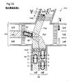
- FIG. 10 is an explanatory diagram for explaining an example of the shape of an intersection in another embodiment 1.
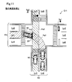
- FIG. 11 is an explanatory diagram for explaining overlapping positions in the second embodiment.
- a vehicle control device 10 according to an embodiment of the present disclosure illustrated in FIG. 1 is mounted on a vehicle and controls traveling when the vehicle travels an intersection.
- the vehicle control apparatus 10 may control a vehicle not only when driving
- a vehicle on which the vehicle control device 10 is mounted is also referred to as “own vehicle”.
- the host vehicle is a vehicle equipped with an engine.
- the own vehicle is a vehicle that can execute automatic driving.
- Automatic driving” means driving that automatically executes engine control, brake control, and steering control on behalf of the driver.
- the host vehicle may be configured to be able to switch between automatic driving and manual driving.
- “Manual operation” means operations for engine control (depressing the accelerator pedal), operations for brake control (depressing the brake pedal), and operations for steering control (rotation of the steering wheel) It means driving performed by the driver.
- the vehicle control device 10 of the present embodiment is configured by an ECU (Electronic Control Unit) equipped with a microcomputer and a memory.
- the vehicle control device 10 is electrically connected to the monitoring sensor 70 and the navigation 80, respectively, and instructs the operation control device 200 to perform control.
- the monitoring sensor 70 is configured by a sensor that detects an object around the host vehicle. “Around the host vehicle” includes the front, side, and rear of the host vehicle.
- the monitoring sensor 70 includes an image sensor 71, a radio wave radar 72, a laser radar 73, and an ultrasonic sensor 74.
- the image sensor 71 is configured by an imaging camera, and acquires a captured image at least ahead of the host vehicle.
- the radio wave radar 72 detects the reflected wave of the radiated radio wave, so that the presence or absence of an object around the host vehicle, the distance between the object and the host vehicle, the position of the object, the size of the object, the shape of the object, and the object shape The relative speed with respect to the host vehicle is detected.
- the laser radar 73 uses infrared laser light to detect the presence or absence of an object around the host vehicle.
- the ultrasonic sensor 74 uses ultrasonic waves to detect the distance between an object and the host vehicle around the host vehicle.
- Navigation 80 provides information on the road on which the vehicle is traveling.
- the navigation 80 has a GNSS sensor 81 and a digital map 82.
- the GNSS sensor 81 is composed of, for example, a GPS (Global Positioning System) sensor, and detects the current position of the host vehicle based on radio waves received from artificial satellites constituting the GPS.
- the digital map 82 is configured by a dynamic map.
- the dynamic map has dynamic information such as traffic jam information in addition to static map information such as road width and lane.
- the operation control device 200 is a functional unit that controls the operation of the host vehicle.
- the operation control apparatus 200 includes an engine ECU 201, a brake ECU 202, a steering ECU 203, and a notification ECU 204.
- the engine ECU 201 controls the operation of the engine 211. Specifically, by controlling various actuators (not shown), the throttle valve opening / closing operation, the igniter ignition operation, the intake valve opening / closing operation, and the like are controlled.
- the brake ECU 202 controls the brake mechanism 212.
- the brake mechanism 212 includes a group of devices (actuators) related to brake control such as sensors, motors, valves, and pumps.
- the brake ECU 202 determines the brake application timing and the brake amount (braking amount), and controls each device constituting the brake mechanism 212 so that the brake amount determined at the determined timing is obtained.
- the steering ECU 203 controls the steering mechanism 213.
- the steering mechanism 213 includes a device group (actuator) related to steering such as a power steering motor.
- the steering ECU 203 determines a steering amount (steering angle) based on a measurement value obtained from a yaw rate sensor or steering angle sensor (not shown), and controls each device constituting the steering mechanism 213 so as to be the determined steering amount.
- the notification ECU 204 controls the notification mechanism 214.
- the notification mechanism 214 includes a display device that displays characters, images, and the like, a speaker that outputs voice, warning sound, and the like, and notifies the driver of various types of information using visual information and auditory information.
- the notification ECU 204 determines the notification content and the timing for executing the notification, and causes the notification mechanism 214 to display and output the notification.
- the vehicle control apparatus 10 includes a road information detection unit 20, an operation detection unit 30, a determination unit 40, and a standby position setting unit 50.
- Each of these functional units 20 to 60 is realized by executing a control program stored in advance in a storage unit (not shown) of the vehicle control device 10 by a microcomputer (not shown) of the vehicle control device 10.
- a control program stored in advance in a storage unit (not shown) of the vehicle control device 10 by a microcomputer (not shown) of the vehicle control device 10.
- the road information detection unit 20 detects information on the road on which the host vehicle is traveling based on the detection result by the monitoring sensor 70 and the information from the navigation 80.
- the road information includes information related to the road structure, information related to a planned travel route based on destination information set in advance in the host vehicle, information related to objects around the host vehicle, and the like. Further, the road information detection unit 20 determines whether or not the host vehicle is scheduled to travel the intersection, and detects information on the intersection where the host vehicle is scheduled to travel.
- “Intersection” means an area including an intersection of two or more roads and the periphery of the intersection.
- Whether or not the host vehicle is scheduled to travel an intersection is determined based on, for example, information on the current position of the host vehicle detected by the GNSS sensor 81 and information on the digital map 82.
- the information on the intersection includes the road structure of the intersection, signal information, information on the oncoming vehicle scheduled to travel at the intersection, the position of other vehicles existing at the intersection, and the like.
- the intersection information may be detected from the detection result or information of at least one of the image sensor 71, the radio wave radar 72, the laser radar 73, the ultrasonic sensor 74, and the digital map 82.
- the road information detection unit 20 includes a travel route detection unit 21, an intersection road detection unit 22, and a situation detection unit 23.
- the travel route detection unit 21 detects the travel route of the host vehicle at the intersection.
- the travel route is specified on the digital map 82 from the information on the current position of the host vehicle detected by the GNSS sensor 81.
- the travel route may be detected from the detection result or information of at least one of the image sensor 71, the radio wave radar 72, the laser radar 73, the ultrasonic sensor 74, and the digital map 82, and preset destination information. May be detected.
- the travel route means a route connecting a lane in which the host vehicle is traveling before passing the intersection and a lane in which the host vehicle is scheduled to travel after passing the intersection. For example, when the host vehicle turns right across the opposite lane at the intersection, a route connecting the lane at the current position of the host vehicle and the lane at the right turn destination is detected as the travel route. Similarly, when traveling straight, a route connecting the lane at the current position of the host vehicle and the lane ahead of the vehicle is detected as a travel route, and when turning left, the lane at the current position of the host vehicle and the lane at the left turn destination Is detected as a travel route.
- the intersection road detection unit 22 detects an intersection road that intersects the traveling route of the host vehicle at the intersection.
- the intersection road is identified on the digital map 82 from the information on the current position of the host vehicle detected by the GNSS sensor 81.
- the intersection road may be detected from at least one detection result or information of the image sensor 71, the radio wave radar 72, the laser radar 73, the ultrasonic sensor 74, and the digital map 82.
- FIG. 2 shows an example in which the host vehicle M1 traveling on the road R1 is going to turn right at the intersection Cr1 where the two roads R1 and R2 intersect.
- the road R1 includes a lane Ln1, a lane Ln2, a lane Ln3, and a lane Ln4, and the road R2 includes a lane Ln5 and a lane Ln6.
- the lane Ln1 is a right turn exclusive lane in which the host vehicle M1 is traveling.
- Lane Ln2 is a lane dedicated to turning right on the opposite lane.
- the lane Ln3 is a straight path of a parallel lane parallel to the lane Ln1.
- Lane Ln4 is a straight path in the opposite lane.
- the road R2 is orthogonal to the road R1.
- Lane Ln5 is a straight path on the side close to the current position of the host vehicle M1
- lane Ln6 is an opposite lane of the lane Ln5 and is a straight path on the side far from the current position of the host vehicle M1.
- the vehicle traveling on the lane Ln5 and the lane Ln6 is not limited to traveling straight at the intersection, and may perform a right turn or a left turn.
- a route connecting the lane Ln1 and the lane Ln6 to the right turn is detected as the travel route Pa1.
- the intersection road Pa2 the lane Ln5 on the side close to the current position of the host vehicle M1 is detected in the road R2 intersecting with the road R1.
- the entire road R2 may be detected as the intersection road Pa2.
- the intersection road Pa2 is detected as a region sandwiched between left and right white lines corresponding to the boundary in the width direction of the lane Ln5.
- the white line it is not limited to the white line, and may be detected as a region sandwiched by boundary lines configured in an arbitrary manner such as a line configured in another color such as yellow or a portion protruding in a strip shape on the road surface. . Further, for example, it may be detected as a region sandwiched between a step at the end portion of the sidewalk and a white line so as to include a shoulder portion, or a region sandwiched between a step at the end portion of the sidewalk and the central separation band.
- the road situation at the operation destination is detected based on the detection result by the monitoring sensor 70 and the information from the navigation 80.
- the road condition at the operation destination may be detected from the detection result or information of at least one of the image sensor 71, the radio wave radar 72, the laser radar 73, the ultrasonic sensor 74, and the digital map 82.
- the motion detection unit 30 detects the schedule of the motion accompanied by the movement of the host vehicle M1 at the intersection Cr1.
- the schedule of the operation corresponds to a schedule of a right turn, a straight turn, a left turn, a turn (U-turn), and the like.
- the scheduled operation is detected based on the current position of the host vehicle M1 detected by the GNSS sensor 81 and destination information set in advance in the host vehicle M1.
- movement may be detected based on the operation result of a direction indicator, for example.
- the determination unit 40 determines whether or not the host vehicle M1 can execute the scheduled operation before the traffic light Sg1 on the travel route Pa1 of the host vehicle M1 at the intersection Cr1 becomes a red signal. Whether or not the scheduled operation can be executed is determined using the road condition of the operation destination detected by the condition detection unit 23. Detailed description of this determination will be described later.
- the “red signal” is a signal indicating a stop.
- the traffic light Sg1 on the travel route Pa1 means the traffic light Sg1 for the lane Ln1 on which the host vehicle M1 is traveling before passing through the intersection Cr1.
- the “until the state of the traffic light Sg1 on the travel route Pa1 becomes a red signal” is not limited to the time when the traffic light changes from a green signal indicating permission to travel to a red signal, but an arrow indicating permission to travel in a specific direction. It is also included until the signal changes from red to red.
- the standby position setting unit 50 sets a standby position at which the host vehicle M1 waits at the intersection Cr1 until the host vehicle M1 becomes ready to execute the scheduled operation at the intersection Cr1. More specifically, until the state of the traffic light Sg1 of the travel route Pa1 of the host vehicle M1 at the intersection Cr1 becomes a red signal, the host vehicle M1 cannot perform the scheduled operation and remains stopped at the standby position. A position where the traveling of the other vehicle M2 traveling on the intersection road Pa2 is not hindered by the own vehicle M1 is set as a standby position. In the present embodiment, a position in front of the overlapping position between the travel route Pa1 and the intersection road Pa2 in the travel route Pa1 is set as the standby position. Detailed description of the overlapping position and the setting of the standby position will be described later.
- the road information detection unit 20 corresponds to a subordinate concept of the intersection information detection unit in the present disclosure
- the motion control device 200 corresponds to a subordinate concept of the guidance unit in the present disclosure.
- Vehicle control processing The vehicle control process shown in FIG. 3 is executed in the vehicle control device 10 from when the start switch of the host vehicle M1 is turned on until it is turned off.
- the road information detection unit 20 detects information on the road on which the host vehicle M1 travels (step S105).
- the road information detection unit 20 determines whether or not the host vehicle M1 is scheduled to travel on the intersection Cr1 (step S110). When it is determined that the host vehicle M1 is not scheduled to travel on the intersection Cr1 (step S110: NO), the process returns to step S105. On the other hand, when it is determined that the host vehicle M1 is scheduled to travel on the intersection Cr1 (step S110: YES), the motion detection unit 30 detects a schedule of an operation involving the movement of the host vehicle M1 at the intersection Cr1 ( Step S115).
- the standby position setting unit 50 determines whether the detected motion schedule corresponds to any one of right turn, straight travel, and turning (step S120). When it is determined that it does not correspond to any one of right turn, straight travel, and turning (step S120: NO), that is, when the detected motion schedule is a left turn, the standby position setting unit 50 sets the standby position. Is not set (step S125). In this case, the motion control apparatus 200 causes the host vehicle M1 to execute a scheduled motion at the intersection Cr1 (step S130). For example, when the engine 211 and the steering mechanism 213 are controlled to turn left so as to follow the preceding vehicle, or when the preceding vehicle temporarily stops according to the situation such as a pedestrian crossing, the brake mechanism 212 and the steering mechanism 213 are controlled.
- step S130 the process returns to step S105.
- step S120 when it is determined that the detected motion schedule corresponds to any one of right turn, straight travel, and turning (step S120: YES), the situation detection unit 23 displays the road condition of the motion destination. Detection is performed (step S135).
- the host vehicle M1 is scheduled to turn right at the intersection Cr1 will be described.
- step S135 the situation detection unit 23 detects a traffic congestion situation or the like of the road at the right turn destination when the host vehicle M1 is scheduled to make a right turn at the intersection Cr1.
- the determination unit 40 can execute the scheduled operation until the state of the traffic light Sg1 of the travel route Pa1 of the host vehicle M1 at the intersection Cr1 becomes a red signal using the detected road condition of the destination. Whether or not (step S140). For example, when the road at the right turn is congested and there is no travel space for the vehicle M1 at the right turn, it is determined that the scheduled motion cannot be executed until the red light is displayed, and there is such travel space. Is determined that the scheduled operation can be executed until the red signal is obtained. Note that the right turn destination travel space corresponds to a space where the host vehicle M1 can enter at the destination of the host vehicle M1.
- step S140 If it is determined that the host vehicle M1 can execute the scheduled operation until the traffic light Sg1 becomes a red signal (step S140: YES), the process proceeds to step S125.
- the motion control device 200 causes the host vehicle M1 to perform a right turn motion without setting a standby position (step S130). For example, when there is an oncoming vehicle that goes straight through the intersection Cr1, the host vehicle M1 is caused to perform a right turn operation after the passing of the oncoming vehicle is completed. For example, when a pedestrian or the like is crossing a pedestrian crossing at a right turn destination, the host vehicle M1 is caused to perform a right turn operation after the pedestrian or the like completes the crossing.
- step S130 the process returns to step S105.
- step S140 NO
- the road information detection unit 20 determines that the travel route Pa1 and the intersection road Pa2 It is determined whether or not the overlapping position has been detected (step S145).
- the overlapping position Ov between the travel route Pa1 and the intersection road Pa2 is indicated by a cross hatch as a region on the road surface, and the standby position SP set in step S155 described later is indicated by a thick solid line. ing.
- the state of the traffic light Sg1 on the travel route Pa1 of the host vehicle M1 is green, and the state of the traffic light Sg2 on the intersection road Pa2 is red.
- the road to the right turn (lane Ln6) is congested.
- step S145 shown in FIG. 3 the travel route detection unit 21 detects the travel route Pa1, and the cross road detection unit 22 detects the cross road Pa2. Based on the detected travel route Pa1 and the cross road Pa2. Then, it is determined whether or not the overlapping position Ov has been detected.
- the standby position setting unit 50 sets the position before the intersection Cr1 as the standby position SP (step S145).
- the case where the overlapping position Ov cannot be detected corresponds to, for example, a case where information from the navigation 80 cannot be obtained due to an unstable communication state.
- the position in front of the intersection Cr1 may be, for example, a position in front of the pedestrian crossing Cw1 in front of the intersection Cr1 in the travel route Pa1.
- the standby position SP may be set on the white line by recognizing the white line on the near side of the pedestrian crossing Cw1 based on the detection result of the image sensor 71.
- the standby position setting unit 50 determines the position in the travel route Pa1 before the overlap position Ov, The standby position SP is set (step S155). The standby position SP is calculated based on the overlapping position Ov. The standby position SP is set at a position before the intersection Cr1.
- the standby position SP is set so as to be in contact with an imaginary line indicating an end portion on the own vehicle M1 side in the width direction of the intersection road Pa2.
- the standby position SP may be set, for example, at a predetermined distance from the overlapping position Ov in the travel route Pa1.
- the standby position SP is set as a line indicating the position of the front end portion in the traveling direction of the host vehicle M1.
- the standby position SP may be set as a section indicating an area occupied by the vehicle body of the host vehicle M1 on the road surface.
- the operation control device 200 guides the host vehicle M1 to the set standby position SP (step S160). More specifically, in order to make the host vehicle M1 stand by at the set standby position SP, the target front / rear position and the target left / right position of the host vehicle M1 are calculated, and the position of the host vehicle M1 and the target front / rear position on the road surface are calculated. The engine 211, the brake mechanism 212, and the steering mechanism 213 are controlled so that the target left-right position matches. As a result, the host vehicle M1 waits (stops) at the standby position SP until the scheduled operation can be executed.
- the notification mechanism 214 notifies the driver of the host vehicle M1 of information related to the standby position SP, so that the host vehicle M1 is set at the set standby position SP. You may induce. For example, an image indicating the intersection Cr1 and the standby position SP may be displayed and guided on the display device that constitutes the notification mechanism 214, and the host vehicle M1 is caused to travel to the standby position SP according to an instruction from a speaker. Then, it may be guided to wait at the standby position SP.
- step S160 After step S160 is completed, the process returns to step S135. For this reason, the own vehicle M1 determines that the own vehicle M1 can execute the scheduled operation until the state of the traffic light Sg1 becomes a red signal based on the road condition of the operation destination (step S140: YES). Then, the vehicle waits (stops) at the standby position SP guided in step S160.
- FIG. 5 shows a state in which the state of the traffic light Sg2 of the intersection road Pa2 intersecting the travel route Pa1 is switched to a green signal after the traffic light Sg1 of the travel route Pa1 of the host vehicle M1 is switched to a red signal.
- the other vehicle M2 traveling straight on the intersection road Pa2 passes through the intersection Cr1.
- the host vehicle M1 is stopped at the standby position SP set before the overlapping position Ov between the travel route Pa1 and the intersection road Pa2. For this reason, the other vehicle M2 can pass the intersection Cr1 without being prevented from traveling by the host vehicle M1 that is stopped.
- the host vehicle M1 cannot execute the scheduled operation until the state of the traffic light Sg1 on the travel route of the host vehicle M1 at the intersection Cr1 becomes a red signal.
- a position before the overlapping position Ov between the travel route Pa1 and the intersection road Pa2 is set as the standby position SP. For this reason, even if the host vehicle M1 cannot perform the scheduled operation and remains stopped at the standby position SP until the traffic light Sg1 becomes a red signal due to traffic congestion on the destination road.
- the traveling of the other vehicle M2 traveling on the intersection road Pa2 can be prevented from being hindered by the host vehicle M1 stopped at the standby position SP.
- the determination unit 40 determines whether or not the host vehicle M1 can execute the scheduled operation by using the road condition of the operation destination detected by the state detection unit 23 until the vehicle turns red. Whether or not the standby position SP is to be set can be determined according to the situation such as traffic congestion on the previous road. For this reason, the waiting position SP is not set when the host vehicle M1 can execute the scheduled operation until there is no traffic jam or the like on the destination road and the traffic light becomes red, so the travel route Pa1 and the intersection road Pa2 The detection of the overlapping position Ov and the arithmetic processing can be omitted, and an increase in the processing load of the vehicle control device 10 can be suppressed.
- the road information detection unit 20 including the travel route detection unit 21, the intersection road detection unit 22, and the situation detection unit 23 detects the information of the intersection Cr 1 based on the detection result by the monitoring sensor 70 and the information from the navigation 80. To do. For this reason, it can suppress that a detection accuracy falls compared with the structure which detects driving
- the overlap position Ov between the travel route Pa1 and the intersection road Pa2 it is determined whether or not the overlap position Ov between the travel route Pa1 and the intersection road Pa2 can be detected. If the overlap position Ov cannot be detected, the position before the intersection Cr1 is set as the standby position SP. It is possible to prevent the standby position SP from being erroneously set at the overlapping position Ov between the route Pa1 and the intersection road Pa2. For this reason, it can suppress that driving
- the standby position SP is not set, so that the detection and calculation processing of the overlapping position Ov between the travel route Pa1 and the intersection road Pa2 can be omitted. An increase in the processing load of the control device 10 can be suppressed.
- the schedule of the operation of the host vehicle M1 at the intersection Cr1 is a left turn, the traffic light Sg1 on the travel route Pa1 of the host vehicle M1 is switched to a red signal due to traffic congestion on the road ahead of the left turn and the overlapping position Ov. Even when the host vehicle M1 stops, the host vehicle M1 can resume running when the traffic congestion is resolved. Therefore, the traveling of the other vehicle M2 traveling on the intersection road Pa2 can be prevented from being hindered by the host vehicle M1.
- FIG. 6 shows a state in which the state of the traffic light Sg2 of the intersection road Pa2 intersecting the travel route Pa1 is changed to a green light after the state of the traffic light Sg1 of the travel route Pa1 of the host vehicle M1 is changed to a red light. In the state shown in FIG.
- the host vehicle M1 cannot execute the scheduled operation until the traffic light Sg1 on the travel route Pa1 becomes a red signal, and at the overlapping position Ov between the travel route Pa1 and the intersection road Pa2. It remains stopped. For this reason, the traveling of the other vehicle M2 traveling straight on the intersection road Pa2 is hindered by the host vehicle M1 stopped in the intersection Cr1.
- the host vehicle M1 cannot execute the scheduled operation until the traffic light Sg1 on the travel route Pa1 of the host vehicle M1 at the intersection Cr1 becomes a red signal. Is determined as the standby position SP, the position before the overlapping position Ov between the travel route Pa1 and the intersection road Pa2. For this reason, even if the host vehicle M1 cannot perform the scheduled operation and remains stopped at the standby position SP until the traffic light Sg1 becomes a red signal due to traffic congestion on the destination road. The traveling of the other vehicle M2 traveling on the intersection road Pa2 can be prevented from being obstructed by the own vehicle M1 stopped at the standby position SP.
- the vehicle control device 10a according to the second embodiment shown in FIG. 7 includes the road information detection unit 20a instead of the road information detection unit 20 and the vehicle control processing procedure according to the first embodiment. And different. Since the other configuration is the same as that of the vehicle control device 10 of the first embodiment, the same reference numeral is given to the same configuration, and detailed description thereof is omitted.
- the road information detection unit 20a in the vehicle control device 10a of the second embodiment further includes a stop line detection unit 24a.
- the stop line detection unit 24a detects a stop line of the travel route Pa1 at the intersection Cr2.
- the stop line is detected based on the detection result by the image sensor 71 and information from the navigation 80.
- the stop line may be detected from the detection result or information of at least one of the image sensor 71 and the digital map 82.
- a stop line SL exists on the right turn travel route Pa1.
- the stop line SL is located on the overlapping position Ov between the travel route Pa1 and the intersection road Pa2. That is, the stop line SL is located in the intersection Cr2.
- the vehicle control process of the second embodiment is the vehicle of the first embodiment in that steps S141a, S142a, and S143a are executed instead of step S125 when step S140 is YES. Different from control processing.
- step S140 When it is determined in step S140 that the host vehicle M1 can execute the scheduled operation until the traffic light Sg1 becomes a red signal (step S140: YES), the standby position setting unit 50 detects the stop line. It is determined whether or not the stop line SL of the travel route Pa1 at the intersection Cr2 is detected by the unit 24a (step S141a). When it is determined that the stop line SL has not been detected (step S141a: NO), the process proceeds to step S125. On the other hand, when it is determined that the stop line SL has been detected (step S141a: YES), the standby position setting unit 50 sets the detected stop line SL as the standby position SP (step S142a).
- the stop line SL in the intersection Cr2 is set to the standby position SP. It is set as. Therefore, the standby position SP set by the standby position setting unit 50 corresponds to the position in the intersection Cr2 set in step S142a and the position in front of the intersection Cr2 set in steps S150 and S155. Become.
- the motion control apparatus 200 guides the host vehicle M1 to the set standby position SP (stop line SL) (step S143a). After step S143a is completed, the process proceeds to step S130.
- the stop line SL detected when it is determined that the host vehicle M1 can execute the scheduled operation until the state of the traffic light Sg1 becomes a red signal. Is set as the standby position SP. For this reason, even if the stop line SL positioned on the overlapping position Ov between the travel route Pa1 and the intersection road Pa2 is set as the standby position SP, the host vehicle M1 is scheduled until the traffic light Sg1 becomes a red signal.
- the standby position SP can be set at a position where the host vehicle M1 is expected to wait in manual operation, and even when automatic operation is performed. Operation close to manual operation can be realized.
- the host vehicle M1 can be prevented from waiting at an excessively front position of the intersection Cr2 in the travel route Pa1, and the smooth travel between the host vehicle M1 and the subsequent vehicle of the host vehicle M1 at the intersection Cr2 is prevented from being hindered. it can.
- a road R3 that intersects the road R1 on which the host vehicle M1 is traveling is bent in the intersection Cr3.
- the other vehicle M2 that travels straight on the intersection road Pa3 turns and travels along the road in the intersection Cr3.
- Such detection of the intersection road Pa3 and the overlapping position Ov2 at the intersection Cr3 may be executed as follows, for example.
- a set of points hereinafter also referred to as “edge E”
- the intersection road Pa3 is detected by creating a virtual line connecting the edges E.
- the overlapping position Ov2 is detected from the detected intersection road Pa3 and travel route Pa1. Then, the standby position SP may be set at a position before the detected overlap position Ov2 in the travel route Pa1. Even with such a configuration, the same effects as those of the above embodiment can be obtained.
- the overlap position Ov between the travel route Pa1 and the intersection road Pa2 and the overlap position Ov2 between the travel route Pa1 and the intersection road Pa3 are detected as regions on the road surface. It is not limited to this.
- the standby position SP may be set at a position before the overlapping position Ov3 detected as a line on the road surface in the travel route Pa1.
- step S120 is YES when the vehicle goes straight or turns. Then, the process may proceed to step S135.
- this disclosure may be applied to the case where it follows the traffic regulation which decided to drive on the right instead of the left side.
- step S120 it may be determined whether or not the detected motion schedule corresponds to any one of left turn, straight travel, and turn.
- the standby position setting unit 50 does not need to set the standby position SP when a right / left turn that does not cross the oncoming lane Ln4 is detected as an operation schedule. Even with this configuration, the same effects as those of the above-described embodiment can be obtained.
- step S140 it is determined whether or not the host vehicle M1 can execute the scheduled operation until the state of the traffic light Sg1 becomes a red signal.
- omitted step S140 may be sufficient.
- the standby position setting unit 50 may set the standby position SP regardless of whether or not the host vehicle M1 can execute the scheduled operation until the traffic light Sg1 becomes a red signal.
- the standby position SP that waits the host vehicle M1 at the intersections Cr1, Cr2, and Cr3 until the situation that the operation involving the movement of the host vehicle M1 at the intersections Cr1, Cr2, and Cr3 can be performed is the standby position SP.
- You may set to the position where the driving
- step S140 when it is determined that the host vehicle M1 can execute the scheduled operation until the traffic light Sg1 becomes red (step S140: YES).
- step S141a the order of step S140 and step S141a may be reversed.
- step S145 when it is determined that the stop line SL has not been detected (step S141a: NO), the process proceeds to step S145, and the position before the intersection Cr2 may be set as the standby position SP in step S150 or step S155. . Even with this configuration, the same effects as those of the second embodiment can be obtained.
- the method for detecting the travel route Pa1 and the intersection roads Pa2, Pa3, etc. in the above embodiment is merely an example, and various changes can be made.
- the reference of the digital map 82 may be omitted, and the travel route Pa1, the intersection roads Pa2, Pa3, and the like may be detected from the detection result of the monitoring sensor 70 of the host vehicle M1.
- the cross roads Pa2 and Pa3 may be estimated and detected based on the shape of. Even with this configuration, the same effects as those of the above-described embodiment can be obtained.
- the configuration of the vehicle control devices 10 and 10a in the above embodiment is merely an example, and various changes can be made.
- the vehicle control devices 10 and 10a may include the operation control device 200.
- the setting of the standby position SP and the guidance to the set standby position SP can be realized with one device.
- the navigation 80 of the host vehicle M1 may further include other devices such as a communication device.
- the communication device can execute, for example, wireless communication with an intelligent transportation system, vehicle-to-vehicle communication with other vehicles, and road-to-vehicle communication with a roadside radio installed in road equipment. It may be configured. According to such a configuration, information obtained by wireless communication can be used for detecting the travel route Pa1, the cross roads Pa2, Pa3, and the like.
- the vehicle control devices 10 and 10a in the above-described embodiment are mounted and used in the own vehicle M1 using an engine as a power source and capable of performing automatic driving, the present disclosure is limited to this. is not.
- the vehicle control devices 10 and 10a may be mounted on a vehicle that can execute only manual operation.
- the vehicle control devices 10 and 10a may be mounted on a fuel cell vehicle, a hybrid vehicle, an electric vehicle, or the like.
- a part of the configuration realized by hardware may be replaced with software.
- a part of the configuration realized by software is replaced with hardware.
- at least one functional unit of the road information detection unit 20, the motion detection unit 30, the determination unit 40, and the standby position setting unit 50 is realized by an integrated circuit, a discrete circuit, or a module that combines these circuits. Also good.
- the software (computer program) can be provided in a form stored in a computer-readable recording medium.
- Computer-readable recording medium is not limited to a portable recording medium such as a flexible disk or a CD-ROM, but is also fixed to an internal storage device in a computer such as various types of RAM and ROM, or a computer such as a hard disk. It also includes an external storage device. That is, the “computer-readable recording medium” has a broad meaning including an arbitrary recording medium capable of fixing a data packet instead of temporarily.
- the present disclosure is not limited to the above-described embodiments, and can be realized with various configurations without departing from the spirit of the present disclosure.
- the technical features in the embodiments corresponding to the technical features in the embodiments described in the summary section of the invention are intended to solve part or all of the above-described problems or to achieve one of the above-described effects. In order to achieve part or all, replacement or combination can be appropriately performed. Further, if the technical feature is not described as essential in the present specification, it can be deleted as appropriate.
Landscapes
- Engineering & Computer Science (AREA)
- Automation & Control Theory (AREA)
- Transportation (AREA)
- Mechanical Engineering (AREA)
- Radar, Positioning & Navigation (AREA)
- Remote Sensing (AREA)
- Physics & Mathematics (AREA)
- General Physics & Mathematics (AREA)
- Human Computer Interaction (AREA)
- Traffic Control Systems (AREA)
- Navigation (AREA)
- Control Of Driving Devices And Active Controlling Of Vehicle (AREA)
Priority Applications (1)
| Application Number | Priority Date | Filing Date | Title |
|---|---|---|---|
| US17/103,791 US11834046B2 (en) | 2018-05-25 | 2020-11-24 | Vehicle control apparatus |
Applications Claiming Priority (2)
| Application Number | Priority Date | Filing Date | Title |
|---|---|---|---|
| JP2018100546A JP2019202722A (ja) | 2018-05-25 | 2018-05-25 | 車両制御装置 |
| JP2018-100546 | 2018-05-25 |
Related Child Applications (1)
| Application Number | Title | Priority Date | Filing Date |
|---|---|---|---|
| US17/103,791 Continuation US11834046B2 (en) | 2018-05-25 | 2020-11-24 | Vehicle control apparatus |
Publications (1)
| Publication Number | Publication Date |
|---|---|
| WO2019225579A1 true WO2019225579A1 (ja) | 2019-11-28 |
Family
ID=68616999
Family Applications (1)
| Application Number | Title | Priority Date | Filing Date |
|---|---|---|---|
| PCT/JP2019/020045 Ceased WO2019225579A1 (ja) | 2018-05-25 | 2019-05-21 | 車両制御装置 |
Country Status (3)
| Country | Link |
|---|---|
| US (1) | US11834046B2 (enExample) |
| JP (1) | JP2019202722A (enExample) |
| WO (1) | WO2019225579A1 (enExample) |
Families Citing this family (11)
| Publication number | Priority date | Publication date | Assignee | Title |
|---|---|---|---|---|
| JP7307673B2 (ja) * | 2019-12-26 | 2023-07-12 | 日産自動車株式会社 | 運転支援方法及び運転支援装置 |
| EP4071441A4 (en) * | 2020-01-02 | 2022-12-28 | Huawei Technologies Co., Ltd. | METHOD AND APPARATUS FOR PROCESSING PREDICTED TRACKS AND METHOD AND APPARATUS FOR DISPLAYING THE BOUNDARY BARRIER |
| CN111380555A (zh) * | 2020-02-28 | 2020-07-07 | 北京京东乾石科技有限公司 | 车辆行为预测方法及装置、电子设备、存储介质 |
| KR102254195B1 (ko) * | 2020-12-03 | 2021-05-21 | 렉스젠(주) | 교통 감응 신호에 대한 안내를 제공하기 위한 교통 제어 시스템 및 그에 관한 방법 |
| CN116997495A (zh) * | 2021-03-17 | 2023-11-03 | 日产自动车株式会社 | 车辆的行驶控制方法以及行驶控制装置 |
| CN115871651A (zh) * | 2021-09-28 | 2023-03-31 | 本田技研工业株式会社 | 驾驶辅助控制装置的驾驶辅助控制方法 |
| JP2023080504A (ja) * | 2021-11-30 | 2023-06-09 | 株式会社アイシン | 運転支援装置及びコンピュータプログラム |
| JP2023135487A (ja) * | 2022-03-15 | 2023-09-28 | 株式会社Subaru | 車両の走行制御装置 |
| US12311903B2 (en) * | 2022-10-07 | 2025-05-27 | GM Global Technology Operations LLC | Vehicle collision mitigation |
| CN116238487B (zh) * | 2022-12-27 | 2025-11-21 | 云控智行科技有限公司 | 一种车辆感知范围的确定方法、装置及设备 |
| JPWO2024172117A1 (enExample) * | 2023-02-17 | 2024-08-22 |
Citations (2)
| Publication number | Priority date | Publication date | Assignee | Title |
|---|---|---|---|---|
| JP2016015168A (ja) * | 2015-10-02 | 2016-01-28 | 住友電気工業株式会社 | 車載装置 |
| JP2018018389A (ja) * | 2016-07-29 | 2018-02-01 | パナソニックIpマネジメント株式会社 | 自動運転車輌の制御装置、及び制御プログラム |
Family Cites Families (9)
| Publication number | Priority date | Publication date | Assignee | Title |
|---|---|---|---|---|
| US9707960B2 (en) * | 2014-07-31 | 2017-07-18 | Waymo Llc | Traffic signal response for autonomous vehicles |
| MX358892B (es) * | 2014-08-21 | 2018-09-07 | Nissan Motor | Dispositivo de asistencia a la conduccion y metodo de asistencia a la conduccion. |
| RU2692097C1 (ru) * | 2015-05-26 | 2019-06-21 | Ниссан Мотор Ко., Лтд. | Устройство и способ задания позиции остановки транспортного средства |
| JP6547434B2 (ja) * | 2015-06-15 | 2019-07-24 | 日産自動車株式会社 | 停車位置設定装置及び方法 |
| KR20190040274A (ko) * | 2016-09-23 | 2019-04-17 | 닛산 지도우샤 가부시키가이샤 | 운전 지원 방법 및 운전 지원 장치 |
| US10576984B2 (en) * | 2017-07-06 | 2020-03-03 | Toyota Research Institute, Inc. | Second stop position for intersection turn |
| JP6658691B2 (ja) * | 2017-07-26 | 2020-03-04 | トヨタ自動車株式会社 | 走行支援装置 |
| US10198002B2 (en) * | 2017-11-21 | 2019-02-05 | GM Global Technology Operations LLC | Systems and methods for unprotected left turns in high traffic situations in autonomous vehicles |
| EP3744599B1 (en) * | 2018-01-25 | 2021-12-15 | Nissan Motor Co., Ltd. | Automatic driving vehicle control method and control device |
-
2018
- 2018-05-25 JP JP2018100546A patent/JP2019202722A/ja active Pending
-
2019
- 2019-05-21 WO PCT/JP2019/020045 patent/WO2019225579A1/ja not_active Ceased
-
2020
- 2020-11-24 US US17/103,791 patent/US11834046B2/en active Active
Patent Citations (2)
| Publication number | Priority date | Publication date | Assignee | Title |
|---|---|---|---|---|
| JP2016015168A (ja) * | 2015-10-02 | 2016-01-28 | 住友電気工業株式会社 | 車載装置 |
| JP2018018389A (ja) * | 2016-07-29 | 2018-02-01 | パナソニックIpマネジメント株式会社 | 自動運転車輌の制御装置、及び制御プログラム |
Also Published As
| Publication number | Publication date |
|---|---|
| JP2019202722A (ja) | 2019-11-28 |
| US11834046B2 (en) | 2023-12-05 |
| US20210094548A1 (en) | 2021-04-01 |
Similar Documents
| Publication | Publication Date | Title |
|---|---|---|
| WO2019225579A1 (ja) | 車両制御装置 | |
| JP7119653B2 (ja) | 車両制御装置 | |
| JP6365390B2 (ja) | 車線変更支援装置 | |
| CN111226267B (zh) | 驾驶辅助车辆的行驶控制方法及行驶控制装置 | |
| CN106080597B (zh) | 自动驾驶车辆系统 | |
| JP6432679B2 (ja) | 停車位置設定装置及び方法 | |
| US20180281803A1 (en) | Vehicle control device | |
| US9896098B2 (en) | Vehicle travel control device | |
| CN110799403B (zh) | 车辆控制装置 | |
| US20220390251A1 (en) | Information processing apparatus and vehicle | |
| JP7156252B2 (ja) | 運転支援装置 | |
| CN106541946A (zh) | 车速控制装置 | |
| JP2016212630A (ja) | 走行制御装置 | |
| CN110447057B (zh) | 车辆控制装置 | |
| CN114761300A (zh) | 驾驶控制方法及驾驶控制装置 | |
| CN110171415A (zh) | 车辆控制装置 | |
| US20190120634A1 (en) | Vehicle control device | |
| WO2020148561A1 (ja) | 運転支援方法及び運転支援装置 | |
| WO2019077669A1 (ja) | 車両制御装置 | |
| WO2019202859A1 (ja) | 走行制御装置 | |
| JP2020100258A (ja) | 車両制御装置 | |
| JP7729913B2 (ja) | 車両制御装置 | |
| JP7564385B2 (ja) | 車両制御装置 | |
| JP7043982B2 (ja) | 車両制御装置 | |
| JPWO2019021422A1 (ja) | 運転支援車両の右左折判断方法及び右左折判断装置 |
Legal Events
| Date | Code | Title | Description |
|---|---|---|---|
| 121 | Ep: the epo has been informed by wipo that ep was designated in this application |
Ref document number: 19807193 Country of ref document: EP Kind code of ref document: A1 |
|
| NENP | Non-entry into the national phase |
Ref country code: DE |
|
| 122 | Ep: pct application non-entry in european phase |
Ref document number: 19807193 Country of ref document: EP Kind code of ref document: A1 |