WO2019224976A1 - 自動車部品 - Google Patents
自動車部品 Download PDFInfo
- Publication number
- WO2019224976A1 WO2019224976A1 PCT/JP2018/019998 JP2018019998W WO2019224976A1 WO 2019224976 A1 WO2019224976 A1 WO 2019224976A1 JP 2018019998 W JP2018019998 W JP 2018019998W WO 2019224976 A1 WO2019224976 A1 WO 2019224976A1
- Authority
- WO
- WIPO (PCT)
- Prior art keywords
- metal plate
- automobile part
- liner layer
- part according
- reinforcing member
- Prior art date
Links
- 229910052751 metal Inorganic materials 0.000 claims abstract description 107
- 239000002184 metal Substances 0.000 claims abstract description 107
- 230000003014 reinforcing effect Effects 0.000 claims abstract description 59
- 229920005992 thermoplastic resin Polymers 0.000 claims abstract description 39
- 229920000049 Carbon (fiber) Polymers 0.000 claims description 18
- 239000004917 carbon fiber Substances 0.000 claims description 18
- VNWKTOKETHGBQD-UHFFFAOYSA-N methane Chemical compound C VNWKTOKETHGBQD-UHFFFAOYSA-N 0.000 claims description 13
- 230000002787 reinforcement Effects 0.000 abstract description 6
- 238000002347 injection Methods 0.000 description 24
- 239000007924 injection Substances 0.000 description 24
- 239000000853 adhesive Substances 0.000 description 14
- 230000001070 adhesive effect Effects 0.000 description 14
- 239000000463 material Substances 0.000 description 13
- 229910052782 aluminium Inorganic materials 0.000 description 12
- XAGFODPZIPBFFR-UHFFFAOYSA-N aluminium Chemical compound [Al] XAGFODPZIPBFFR-UHFFFAOYSA-N 0.000 description 12
- 238000000034 method Methods 0.000 description 11
- 238000003486 chemical etching Methods 0.000 description 6
- 238000003466 welding Methods 0.000 description 6
- 239000011199 continuous fiber reinforced thermoplastic Substances 0.000 description 5
- 238000000465 moulding Methods 0.000 description 5
- 229920005989 resin Polymers 0.000 description 5
- 239000011347 resin Substances 0.000 description 5
- IKDUDTNKRLTJSI-UHFFFAOYSA-N hydrazine hydrate Chemical compound O.NN IKDUDTNKRLTJSI-UHFFFAOYSA-N 0.000 description 4
- 238000007788 roughening Methods 0.000 description 4
- 230000003746 surface roughness Effects 0.000 description 4
- 239000007864 aqueous solution Substances 0.000 description 3
- 239000004918 carbon fiber reinforced polymer Substances 0.000 description 3
- 239000012141 concentrate Substances 0.000 description 3
- 230000007547 defect Effects 0.000 description 3
- 230000000694 effects Effects 0.000 description 3
- 239000004033 plastic Substances 0.000 description 3
- QGZKDVFQNNGYKY-UHFFFAOYSA-N Ammonia Chemical compound N QGZKDVFQNNGYKY-UHFFFAOYSA-N 0.000 description 2
- OAKJQQAXSVQMHS-UHFFFAOYSA-N Hydrazine Chemical compound NN OAKJQQAXSVQMHS-UHFFFAOYSA-N 0.000 description 2
- XEEYBQQBJWHFJM-UHFFFAOYSA-N Iron Chemical compound [Fe] XEEYBQQBJWHFJM-UHFFFAOYSA-N 0.000 description 2
- 229920002292 Nylon 6 Polymers 0.000 description 2
- -1 amine compound Chemical class 0.000 description 2
- 239000002131 composite material Substances 0.000 description 2
- 230000008602 contraction Effects 0.000 description 2
- 230000007423 decrease Effects 0.000 description 2
- 239000000835 fiber Substances 0.000 description 2
- 238000005259 measurement Methods 0.000 description 2
- 239000007769 metal material Substances 0.000 description 2
- 238000005498 polishing Methods 0.000 description 2
- 238000001878 scanning electron micrograph Methods 0.000 description 2
- XLYOFNOQVPJJNP-UHFFFAOYSA-N water Substances O XLYOFNOQVPJJNP-UHFFFAOYSA-N 0.000 description 2
- 229910001369 Brass Inorganic materials 0.000 description 1
- RYGMFSIKBFXOCR-UHFFFAOYSA-N Copper Chemical compound [Cu] RYGMFSIKBFXOCR-UHFFFAOYSA-N 0.000 description 1
- FYYHWMGAXLPEAU-UHFFFAOYSA-N Magnesium Chemical compound [Mg] FYYHWMGAXLPEAU-UHFFFAOYSA-N 0.000 description 1
- 229920002302 Nylon 6,6 Polymers 0.000 description 1
- 239000004734 Polyphenylene sulfide Substances 0.000 description 1
- 239000004954 Polyphthalamide Substances 0.000 description 1
- RTAQQCXQSZGOHL-UHFFFAOYSA-N Titanium Chemical compound [Ti] RTAQQCXQSZGOHL-UHFFFAOYSA-N 0.000 description 1
- 239000002253 acid Substances 0.000 description 1
- 238000010306 acid treatment Methods 0.000 description 1
- 239000012670 alkaline solution Substances 0.000 description 1
- 229910021529 ammonia Inorganic materials 0.000 description 1
- 239000011324 bead Substances 0.000 description 1
- 238000005452 bending Methods 0.000 description 1
- 239000010951 brass Substances 0.000 description 1
- 238000001816 cooling Methods 0.000 description 1
- 239000010949 copper Substances 0.000 description 1
- 229910052802 copper Inorganic materials 0.000 description 1
- 238000005520 cutting process Methods 0.000 description 1
- 238000005238 degreasing Methods 0.000 description 1
- 238000011156 evaluation Methods 0.000 description 1
- 239000003365 glass fiber Substances 0.000 description 1
- 238000010438 heat treatment Methods 0.000 description 1
- 229910052742 iron Inorganic materials 0.000 description 1
- 238000004898 kneading Methods 0.000 description 1
- 239000007788 liquid Substances 0.000 description 1
- 239000011777 magnesium Substances 0.000 description 1
- 229910052749 magnesium Inorganic materials 0.000 description 1
- 150000002739 metals Chemical class 0.000 description 1
- 239000002991 molded plastic Substances 0.000 description 1
- 238000006386 neutralization reaction Methods 0.000 description 1
- 238000005192 partition Methods 0.000 description 1
- 229920001707 polybutylene terephthalate Polymers 0.000 description 1
- 229920000069 polyphenylene sulfide Polymers 0.000 description 1
- 229920006375 polyphtalamide Polymers 0.000 description 1
- 239000011148 porous material Substances 0.000 description 1
- 238000003825 pressing Methods 0.000 description 1
- 239000012783 reinforcing fiber Substances 0.000 description 1
- 239000004576 sand Substances 0.000 description 1
- 238000005488 sandblasting Methods 0.000 description 1
- 238000000926 separation method Methods 0.000 description 1
- 238000010008 shearing Methods 0.000 description 1
- 239000000243 solution Substances 0.000 description 1
- 229910001220 stainless steel Inorganic materials 0.000 description 1
- 239000010935 stainless steel Substances 0.000 description 1
- 239000010936 titanium Substances 0.000 description 1
- 229910052719 titanium Inorganic materials 0.000 description 1
Images


Classifications
-
- B—PERFORMING OPERATIONS; TRANSPORTING
- B62—LAND VEHICLES FOR TRAVELLING OTHERWISE THAN ON RAILS
- B62D—MOTOR VEHICLES; TRAILERS
- B62D29/00—Superstructures, understructures, or sub-units thereof, characterised by the material thereof
- B62D29/001—Superstructures, understructures, or sub-units thereof, characterised by the material thereof characterised by combining metal and synthetic material
- B62D29/004—Superstructures, understructures, or sub-units thereof, characterised by the material thereof characterised by combining metal and synthetic material the metal being over-moulded by the synthetic material, e.g. in a mould
-
- B—PERFORMING OPERATIONS; TRANSPORTING
- B29—WORKING OF PLASTICS; WORKING OF SUBSTANCES IN A PLASTIC STATE IN GENERAL
- B29C—SHAPING OR JOINING OF PLASTICS; SHAPING OF MATERIAL IN A PLASTIC STATE, NOT OTHERWISE PROVIDED FOR; AFTER-TREATMENT OF THE SHAPED PRODUCTS, e.g. REPAIRING
- B29C45/00—Injection moulding, i.e. forcing the required volume of moulding material through a nozzle into a closed mould; Apparatus therefor
- B29C45/14—Injection moulding, i.e. forcing the required volume of moulding material through a nozzle into a closed mould; Apparatus therefor incorporating preformed parts or layers, e.g. injection moulding around inserts or for coating articles
- B29C45/14311—Injection moulding, i.e. forcing the required volume of moulding material through a nozzle into a closed mould; Apparatus therefor incorporating preformed parts or layers, e.g. injection moulding around inserts or for coating articles using means for bonding the coating to the articles
-
- B—PERFORMING OPERATIONS; TRANSPORTING
- B32—LAYERED PRODUCTS
- B32B—LAYERED PRODUCTS, i.e. PRODUCTS BUILT-UP OF STRATA OF FLAT OR NON-FLAT, e.g. CELLULAR OR HONEYCOMB, FORM
- B32B15/00—Layered products comprising a layer of metal
- B32B15/04—Layered products comprising a layer of metal comprising metal as the main or only constituent of a layer, which is next to another layer of the same or of a different material
- B32B15/08—Layered products comprising a layer of metal comprising metal as the main or only constituent of a layer, which is next to another layer of the same or of a different material of synthetic resin
-
- B—PERFORMING OPERATIONS; TRANSPORTING
- B32—LAYERED PRODUCTS
- B32B—LAYERED PRODUCTS, i.e. PRODUCTS BUILT-UP OF STRATA OF FLAT OR NON-FLAT, e.g. CELLULAR OR HONEYCOMB, FORM
- B32B3/00—Layered products comprising a layer with external or internal discontinuities or unevennesses, or a layer of non-planar shape; Layered products comprising a layer having particular features of form
- B32B3/26—Layered products comprising a layer with external or internal discontinuities or unevennesses, or a layer of non-planar shape; Layered products comprising a layer having particular features of form characterised by a particular shape of the outline of the cross-section of a continuous layer; characterised by a layer with cavities or internal voids ; characterised by an apertured layer
- B32B3/30—Layered products comprising a layer with external or internal discontinuities or unevennesses, or a layer of non-planar shape; Layered products comprising a layer having particular features of form characterised by a particular shape of the outline of the cross-section of a continuous layer; characterised by a layer with cavities or internal voids ; characterised by an apertured layer characterised by a layer formed with recesses or projections, e.g. hollows, grooves, protuberances, ribs
-
- B—PERFORMING OPERATIONS; TRANSPORTING
- B32—LAYERED PRODUCTS
- B32B—LAYERED PRODUCTS, i.e. PRODUCTS BUILT-UP OF STRATA OF FLAT OR NON-FLAT, e.g. CELLULAR OR HONEYCOMB, FORM
- B32B7/00—Layered products characterised by the relation between layers; Layered products characterised by the relative orientation of features between layers, or by the relative values of a measurable parameter between layers, i.e. products comprising layers having different physical, chemical or physicochemical properties; Layered products characterised by the interconnection of layers
- B32B7/04—Interconnection of layers
-
- B—PERFORMING OPERATIONS; TRANSPORTING
- B62—LAND VEHICLES FOR TRAVELLING OTHERWISE THAN ON RAILS
- B62D—MOTOR VEHICLES; TRAILERS
- B62D25/00—Superstructure or monocoque structure sub-units; Parts or details thereof not otherwise provided for
- B62D25/02—Side panels
-
- B—PERFORMING OPERATIONS; TRANSPORTING
- B29—WORKING OF PLASTICS; WORKING OF SUBSTANCES IN A PLASTIC STATE IN GENERAL
- B29C—SHAPING OR JOINING OF PLASTICS; SHAPING OF MATERIAL IN A PLASTIC STATE, NOT OTHERWISE PROVIDED FOR; AFTER-TREATMENT OF THE SHAPED PRODUCTS, e.g. REPAIRING
- B29C45/00—Injection moulding, i.e. forcing the required volume of moulding material through a nozzle into a closed mould; Apparatus therefor
- B29C45/14—Injection moulding, i.e. forcing the required volume of moulding material through a nozzle into a closed mould; Apparatus therefor incorporating preformed parts or layers, e.g. injection moulding around inserts or for coating articles
- B29C2045/1486—Details, accessories and auxiliary operations
- B29C2045/14868—Pretreatment of the insert, e.g. etching, cleaning
-
- B—PERFORMING OPERATIONS; TRANSPORTING
- B29—WORKING OF PLASTICS; WORKING OF SUBSTANCES IN A PLASTIC STATE IN GENERAL
- B29K—INDEXING SCHEME ASSOCIATED WITH SUBCLASSES B29B, B29C OR B29D, RELATING TO MOULDING MATERIALS OR TO MATERIALS FOR MOULDS, REINFORCEMENTS, FILLERS OR PREFORMED PARTS, e.g. INSERTS
- B29K2101/00—Use of unspecified macromolecular compounds as moulding material
- B29K2101/12—Thermoplastic materials
-
- B—PERFORMING OPERATIONS; TRANSPORTING
- B29—WORKING OF PLASTICS; WORKING OF SUBSTANCES IN A PLASTIC STATE IN GENERAL
- B29K—INDEXING SCHEME ASSOCIATED WITH SUBCLASSES B29B, B29C OR B29D, RELATING TO MOULDING MATERIALS OR TO MATERIALS FOR MOULDS, REINFORCEMENTS, FILLERS OR PREFORMED PARTS, e.g. INSERTS
- B29K2307/00—Use of elements other than metals as reinforcement
- B29K2307/04—Carbon
-
- B—PERFORMING OPERATIONS; TRANSPORTING
- B29—WORKING OF PLASTICS; WORKING OF SUBSTANCES IN A PLASTIC STATE IN GENERAL
- B29K—INDEXING SCHEME ASSOCIATED WITH SUBCLASSES B29B, B29C OR B29D, RELATING TO MOULDING MATERIALS OR TO MATERIALS FOR MOULDS, REINFORCEMENTS, FILLERS OR PREFORMED PARTS, e.g. INSERTS
- B29K2705/00—Use of metals, their alloys or their compounds, for preformed parts, e.g. for inserts
-
- B—PERFORMING OPERATIONS; TRANSPORTING
- B29—WORKING OF PLASTICS; WORKING OF SUBSTANCES IN A PLASTIC STATE IN GENERAL
- B29L—INDEXING SCHEME ASSOCIATED WITH SUBCLASS B29C, RELATING TO PARTICULAR ARTICLES
- B29L2031/00—Other particular articles
- B29L2031/30—Vehicles, e.g. ships or aircraft, or body parts thereof
- B29L2031/3002—Superstructures characterized by combining metal and plastics, i.e. hybrid parts
-
- B—PERFORMING OPERATIONS; TRANSPORTING
- B32—LAYERED PRODUCTS
- B32B—LAYERED PRODUCTS, i.e. PRODUCTS BUILT-UP OF STRATA OF FLAT OR NON-FLAT, e.g. CELLULAR OR HONEYCOMB, FORM
- B32B2250/00—Layers arrangement
- B32B2250/02—2 layers
-
- B—PERFORMING OPERATIONS; TRANSPORTING
- B32—LAYERED PRODUCTS
- B32B—LAYERED PRODUCTS, i.e. PRODUCTS BUILT-UP OF STRATA OF FLAT OR NON-FLAT, e.g. CELLULAR OR HONEYCOMB, FORM
- B32B2255/00—Coating on the layer surface
- B32B2255/06—Coating on the layer surface on metal layer
-
- B—PERFORMING OPERATIONS; TRANSPORTING
- B32—LAYERED PRODUCTS
- B32B—LAYERED PRODUCTS, i.e. PRODUCTS BUILT-UP OF STRATA OF FLAT OR NON-FLAT, e.g. CELLULAR OR HONEYCOMB, FORM
- B32B2262/00—Composition or structural features of fibres which form a fibrous or filamentary layer or are present as additives
- B32B2262/10—Inorganic fibres
- B32B2262/106—Carbon fibres, e.g. graphite fibres
-
- B—PERFORMING OPERATIONS; TRANSPORTING
- B32—LAYERED PRODUCTS
- B32B—LAYERED PRODUCTS, i.e. PRODUCTS BUILT-UP OF STRATA OF FLAT OR NON-FLAT, e.g. CELLULAR OR HONEYCOMB, FORM
- B32B2307/00—Properties of the layers or laminate
- B32B2307/70—Other properties
- B32B2307/732—Dimensional properties
-
- B—PERFORMING OPERATIONS; TRANSPORTING
- B32—LAYERED PRODUCTS
- B32B—LAYERED PRODUCTS, i.e. PRODUCTS BUILT-UP OF STRATA OF FLAT OR NON-FLAT, e.g. CELLULAR OR HONEYCOMB, FORM
- B32B2605/00—Vehicles
Definitions
- the present invention relates to an automobile part using a composite of a thermoplastic resin and a metal plate, and more particularly to an automobile part in which a thermoplastic resin and a metal plate are directly bonded.
- the weight of a vehicle is reduced by using a composite of a resin and a metal member, and an adhesive is frequently used for bonding the resin and the metal material.
- Japanese Patent No. 5523849 of Patent Document 1 discloses a vehicle body structure in which a space formed between an outer frame and an inner frame manufactured from a metal sheet is reinforced by a reinforcing structure composed of integrally molded plastic. The frame side member is described.
- the frame manufactured from the metal sheet is provided with perforations, and the plastic peg is passed through and spread on the surface of the perforations, so that a rigid and discontinuous meshing connection between the frame manufactured from the metal sheets and the plastic can be achieved Is disclosed.
- the present invention has been made in view of such problems of the prior art, and an object of the present invention is to provide an automobile part that prevents the thermoplastic resin and the metal plate from peeling off.
- the present inventor provided a liner layer covering the metal plate on the metal plate side of the reinforcing member, and the entire one surface of the liner layer was formed on the metal plate.
- the inventors have found that the above object can be achieved by directly adhering to each other, and have completed the present invention.
- the automobile part of the present invention includes a metal plate and a reinforcing member including a thermoplastic resin disposed on one surface of the metal plate.
- the reinforcing member includes a liner layer that covers the metal plate, and a reinforcing structure that is erected on the liner layer and reinforces the metal plate. The entire one surface of the liner layer is directly bonded to the metal plate.
- the reinforcing member having the liner layer covering the metal plate is provided, and the entire one surface of the liner layer is adhered to the metal plate and directly bonded thereto. It is possible to provide an automobile part that is prevented from peeling off from the metal plate.
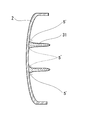
- FIG. 2 is a cross-sectional view of a portion indicated by A-A ′ in FIG. 1. It is sectional drawing which expanded the adhesion interface of a metal plate and a thermoplastic resin typically. It is sectional drawing which shows the adhesion state of the reinforcement member (thermoplastic resin) and metal plate which were formed only with the reinforcement structure part. It is sectional drawing which shows the state in which the liner layer was continuously provided from the one surface of the metal plate to the other surface.
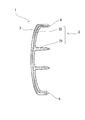
- FIG. 2 is a cross-sectional view of a surface along a reinforcing structure portion indicated by B-B ′ in FIG. 1. It is sectional drawing which shows the state which welded the exposure part and metal plate of motor vehicle parts. It is sectional drawing which shows the state which welded two motor vehicle parts by the exposed part. 2 is an SEM image of the aluminum plate surface of Example 1.
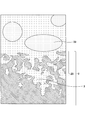
- FIG. 1 is an SEM image of the aluminum plate surface of Example 1.
- the automobile component of the present invention includes a metal plate and a reinforcing member including a thermoplastic resin disposed on one surface of the metal plate.
- the thermoplastic resin can contain reinforcing fibers such as carbon fibers and glass fibers.
- carbon fibers can be preferably used because they can provide lightweight and highly rigid automobile parts.
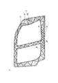
- FIG. 1 is a plan view of an automobile part of the present invention as viewed from the reinforcing member (CFRTP) side
- FIG. 2 is a cross-sectional view taken along the line AA ′ in FIG.
- the automobile part 1 has a reinforcing member 3 formed of the metal plate 2 and CFRTP.
- the reinforcing member 3 has a continuous liner layer 32 that covers the metal plate 2 as well as the reinforcing structure portion 31 such as ribs and beads, and the reinforcing structure portion 31 and the reinforcing structure portion 31 standing on the liner layer 32 are reinforced.
- the space between the structural portions 31 is covered with the liner layer 32 without any gap.
- the projected area of the liner layer 32 when the reinforcing member 3 is viewed from the thickness direction is the projected area of the entire reinforcing member 3, and as shown in FIG.
- a plurality of convex reinforcing structure portions 31 are connected and erected.
- the entire one surface of the liner layer 32 is in close contact with the metal plate 2, and the metal plate 2 and the reinforcing member 3 are directly bonded.
- the entire one surface of the liner layer 32 having a large projected area as described above is an adhesive surface, and the adhesive area between the reinforcing member 3 and the metal plate 2 is large. Therefore, the reinforcing member 3 and the metal plate 2 can be firmly bonded, and peeling can be prevented.
- the automobile part 1 has a liner layer 32 bonded to the metal plate 2, and the liner layer 32 supports the metal plate 2 at a portion where the liner layer 32 is bonded. Therefore, the thickness of the metal plate 2 can be reduced.
- the thickness of the metal plate 2 can be 0.5 mm or more and 2.5 mm or less, and the weight can be significantly reduced.
- the automobile part 1 can be manufactured by an injection press method or a press molding method.
- the injection press method after the injection material is injected with the mold slightly opened, the mold is completely closed and the injection material is pressed, and the injection material is spread over the entire cavity and molded. Is the method.
- the above injection press method can be preferably used because the molten thermoplastic resin is filled in the cavity, so that the thermoplastic resin adheres tightly to the metal plate 2 and can be firmly bonded.
- the molded metal plate is placed in the mold and pressed by the upper mold, and the injection material containing the thermoplastic resin is injected from the lower mold side toward the metal plate with the mold slightly opened. To do. Then, the mold is completely closed and the injection material is pressed together with the metal plate, the injection material is spread over the entire cavity, and a thermoplastic resin is brought into close contact with the metal plate to produce an automobile part. .
- At least one surface of the metal plate 2 is roughened. Since the adhesive surface with the reinforcing member 3 is roughened, it can be more firmly bonded.
- Examples of the roughening treatment include mechanical roughening treatment such as sand blast treatment, liquid honing treatment, buffing, polishing with a polishing sheet, acid treatment, chemical etching, and laser ridge.
- chemical etching and laser ridge can be roughened by forming a hole having an inner diameter larger than the opening diameter, unlike a mechanical surface roughening process, and a thermoplastic resin is formed in the hole by an injection press method.
- a thermoplastic resin is formed in the hole by an injection press method.
- the chemical etching can form a ant nest-like porous structure 23 in which a plurality of spaces are connected by a tunnel, as shown in FIG. 3, and a large anchor effect can be obtained and a stronger adhesion can be obtained.
- the thermoplastic resin 3 is other than the opening part. Since it can penetrate and fill the entire space of the porous structure 23 with the thermoplastic resin 3, it is particularly preferable to use it because it is difficult for filling defects to occur.
- the chemical etching can be performed by immersing the metal plate in an aqueous solution of ammonia, hydrazine and / or a water-soluble amine compound. Specifically, a metal plate can be dipped in a 3% to 10% hydrazine monohydrate aqueous solution heated to 40 ° C to 70 ° C for several minutes, and then washed with water to roughen the surface with fine irregularities. It is.
- metal plate for example, a metal plate such as aluminum, iron, stainless steel, copper, titanium, magnesium, brass, or a metal plate plated with the above metal can be used.
- the surface roughness (Ra) of the roughened metal plate is preferably 5 ⁇ m or less, more preferably 1.2 ⁇ m or less.
- the surface roughness (Ra) of the metal plate is 5 ⁇ m or less, so that even if the surface is roughened to the other surface, irregularities are not conspicuous and a design surface can be formed, and further 1.2 ⁇ m or less. A smooth painted surface can be formed.
- the thermoplastic resin preferably contains carbon fibers having an average fiber diameter of 7 ⁇ m to 15 ⁇ m and an average length of 0.1 mm to 1 mm.
- the thermoplastic resin preferably contains 30% by mass to 40% by mass of the carbon fiber.
- the carbon fiber content satisfies the above range, the rigidity of the automobile part can be improved.
- the content of the carbon fiber exceeds 40% by mass, a large amount of carbon fiber having a high thermal conductivity is included, so that the kneading material (injection material) of the thermoplastic resin and the carbon fiber is cooled and the viscosity is increased. It becomes difficult for the thermoplastic resin to enter the porous structure, causing a filling defect to easily peel off, and the rigidity of the automobile part may be lowered.
- the carbon fiber content is less than 30% by mass, the reinforcing effect of the carbon fiber is small and the rigidity of the automobile part is lowered.
- the viscosity of the injection material at the time of injection pressing is preferably 30 Pa ⁇ s or more and 200 Pa ⁇ s or less, more preferably 30 Pa ⁇ s or more and 50 Pa ⁇ s or less, although it depends on the thermoplastic resin or the injection pressure. . If the viscosity of the injection material is low, the thermoplastic resin is likely to enter the porous structure, but at a temperature of less than 30 Pa ⁇ s, the thermoplastic resin is thermally decomposed, and the adhesive strength tends to decrease.
- thermoplastic resin a thermoplastic resin that can be molded by an injection press method can be used, and examples thereof include nylon 6, nylon 66, polyphenylene sulfide, polybutylene terephthalate, and polyphthalamide.
- the projected area of the liner layer 32 is preferably 50% or more of the projected area of the metal plate 2.
- the metal plate 2 can be thinned and easily cooled, whereas the reinforcing structure portion 31 formed of CFRTP to which the metal plate 2 is bonded is thick and difficult to cool. Becomes larger. Then, a shearing force is generated due to the difference in heat shrinkage after the injection press, and the metal plate 2 is easily deformed and the metal plate 2 and the reinforcing member 3 are easily peeled off.
- the cooling rate of the metal plate 2 is reduced and the thermal strain is dispersed, so that the deformation of the metal plate 2 and the metal plate 2 Peeling from the reinforcing member 3 can be prevented. Furthermore, when the thickness of the liner layer 32 is uniform, thermal strain is reduced.
- the injection material since the injection material is injected with the mold slightly opened, the injection material leaks and the thermoplastic resin is applied outside the desired region.
- the liner layer 32 is formed continuously, and the length of the boundary 5 between the portion where the liner layer 32 shown in FIG. 2 is formed and the portion where the liner layer 32 is not formed is shown. Is shorter than the length of the boundary 5 'of the reinforcing member 3 formed by only the reinforcing structure 31 shown in FIG.
- the length of the boundary 5 is short and the risk of leakage of the thermoplastic resin is small. Therefore, injection press molding with a reduced mold seal structure for preventing leakage of the thermoplastic resin is possible. Therefore, inexpensive molding is possible.
- the projected area of the reinforcing structure portion 31 with respect to the projected area of the liner layer 32 is preferably 30% or less.
- the projected area of the reinforcing structure portion 31 is 30% or less, local deformation of the metal plate 2 that occurs in the vicinity of the reinforcing structure portion 31 due to rib contraction or the like can be prevented.
- the thickness of the liner layer 32 is preferably 1 mm or more and 3 mm or less. If it is less than 1 mm, the cavity is narrow and the filling distance is long, so that it is difficult to form by the injection press method. If it exceeds 3 mm, the effect of reducing the weight is reduced.
- the automobile part 1 preferably has a covering portion 21 covered with a liner layer 32 continuous from the one surface side at the end of the other surface of the metal plate 2. As shown in FIG. 5, by providing the liner layer 32 continuously from one surface of the metal plate 2 to the other surface, a physical fit is formed, and the CFRTP 3 can be prevented from falling off.
- the thermoplastic resin is exposed on the other surface side that is the design surface.
- it may be an automobile part that can cover the thermoplastic resin exposed in a molding such as a door frame of a body side panel. If it is, designability does not fall.
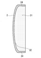
- the metal plate 2 preferably has a bent portion 24 bent toward the liner layer 32 at the end thereof.
- the strength of the metal plate 2 itself is improved by the bent portion 24, and the strength of the automobile part 1 can be improved in combination with the reinforcing member 3.
- the metal plate 2 is provided with the bent portions 24 at both ends thereof, and the cross section of the surface along the reinforcing structure portion 31 indicated by BB ′ in FIG. 1 shows the reinforcing structure as shown in FIG.
- the portion 31 is preferably erected continuously from the bent portion 24 at one end to the bent portion 24 at the other end.
- the automobile part 1 preferably has an exposed portion 22 exposed from the liner layer 32 at the end of one surface of the metal plate 2. By forming the flange and exposing it from the liner layer 32, it becomes possible to weld the metals together. As shown in FIGS. 7 and 8, another metal plate 2 ′ or another automobile part 1 ′ is further provided on the reinforcing member 3 side. And can be joined by welding.
- the bent portion 24 may include a flange portion 25 that is further bent at the end portion in the planar direction of the metal plate. Since the metal plate 2 has a hat shape having the flange portion 25, the strength of the automobile part 1 can be further improved.
- the flange portion 25 is the exposed portion 22 exposed from the liner layer 32, as shown in FIG. 8, it is joined to another metal plate 2 ′ or another automobile part 1 ′ by welding. Can do.
- the length of the exposed portion 22, that is, the length from the end of the metal plate 2 to the end of the liner layer 32 is preferably 5 mm or more and 30 mm or less.
- the length of the exposed portion 22 is less than 5 mm, not only is the welding margin small and welding is difficult, but also the thermoplastic resin is thermally decomposed by the heat of welding to generate voids in the porous structure, and the voids are separated from the origin of separation. As a result, the adhesive strength decreases. Further, when an external force is applied, stress concentrates on the boundary between the portion where the liner layer 32 is bonded and the exposed portion 22, and the reinforcing member 3 is easily peeled off.
- the liner layer 32 and the metal plate 2 are integrated to support the part. Therefore, when the length of the exposed portion 22 exceeds 30 mm and only the metal plate 2 is enlarged, The external force concentrates there and it is easy to be destroyed.
- the automobile part 1 preferably has a sandwich structure in which a reinforcing member 3 is sandwiched between metal plates 2 and 2 'as shown in FIGS.
- the end portion of the liner layer 32 of the reinforcing member 3 and the reinforcing structure portion 31 abut on the other metal plate 2 ′ or the reinforcing member 3 ′ provided on the other metal plate 2 ′ to form a hollow structure. Since the reinforcing structure portion 31 is a partition that divides the hollow structure, the automobile part 1 can be increased in strength and weight.
- the automobile part 1 can be preferably used for a door panel, a back door panel, and the like in addition to a frame member such as a body side panel, a rear fender, and a dash panel.
- Example 1 A press-molded 1 mm thick aluminum plate was immersed in an alkaline solution for degreasing, and then immersed in an acid solution for neutralization. The aluminum plate was immersed in a 5% hydrazine monohydrate aqueous solution heated to 50 ° C. for 5 minutes, then washed with water and dried to obtain an aluminum plate having a roughened surface.
- the aluminum plate is placed in a mold, and while holding the upper mold and heating to 280 ° C., the mold is slightly opened, and 35 carbon fibers having an average fiber diameter of 10 ⁇ m and an average length of 0.5 mm are obtained. A kneaded material of carbon fiber and nylon 6 containing mass% was injected. Thereafter, the mold was completely closed and pressed at 10 MPa to obtain an automobile part having a liner layer thickness of 2 mm.
- Example 2 An automobile part was obtained in the same manner as in Example 1 except that it was roughened by sandblasting and an aluminum plate having a surface roughness (Ra) of 7 ⁇ m was used.
- Example 3 An automobile part was obtained in the same manner as in Example 1 except that the aluminum plate was not roughened.
- the automobile part of the present invention has strong adhesive strength between the metal plate and the reinforcing member containing the thermoplastic resin, and can prevent peeling.
- Example 1 using a metal plate roughened by forming a hole having an inner diameter larger than the opening diameter by chemical etching is 8.4 times as large as Example 2 roughened by mechanical treatment. It has adhesive strength, and it has been confirmed that roughening by chemical etching significantly increases the adhesive strength, and that a high-rigidity automotive part can be obtained by reinforcing with a reinforcing member.
Landscapes
- Engineering & Computer Science (AREA)
- Mechanical Engineering (AREA)
- Chemical & Material Sciences (AREA)
- Combustion & Propulsion (AREA)
- Transportation (AREA)
- Architecture (AREA)
- Structural Engineering (AREA)
- Manufacturing & Machinery (AREA)
- Laminated Bodies (AREA)
- Body Structure For Vehicles (AREA)
Abstract
本発明の自動車部品は、金属プレートと、上記金属プレートの一方の面に配置された熱可塑性樹脂を含む補強部材と、を備える。 そして、上記補強部材が、上記金属プレートを被覆するライナー層と、該ライナー層に立設され上記金属プレートを補強する補強構造部とを有し、上記ライナー層の一方の面の全体が上記金属プレートに密着し、上記金属プレートと上記補強部材とが、直接接着されており、補強部材と金属プレートとの剥がれを防止した自動車部品を提供することができる。
Description
本発明は、熱可塑性樹脂と金属プレートとの複合体を用いた自動車部品に係り、更に詳細には、熱可塑性樹脂と金属プレートとが直接接着した自動車部品に関する。
自動車部品においては、樹脂と金属部材との複合体を用いて車両重量の軽量化が図られており、樹脂と金属材との接着には、接着剤が多用されている。
樹脂と金属材とを接着する接着剤が多く開発されてはいるが、金属部材と樹脂とでは熱収縮率が異なるため、金属部材と樹脂に挟まれた接着剤に残留剪断応力が発生し、接着剤が破断して剥離が生じやすい。
特許文献1の日本国特許5523849号公報には、金属シートから製造された外枠と内枠との間に形成された空間が、一体成形プラスチックから構成される補強構造物により強化された車体構造の枠側部材が記載されている。
そして、金属シートから製造された枠に穿孔を設け、プラスチックペグを通過させて穿孔の表面に拡げることで、金属シートから製造された枠とプラスチックとの堅固で不連続な噛み合い連結を達成できる旨が開示されている。
しかしながら、特許文献1に記載の枠側部材にあっては、不連続な噛み合い連結に応力が集中し易く、また、金属製の枠とプラスチックとの接着面積が小さいため剥がれが発生する。
本発明は、このような従来技術の有する課題に鑑みてなされたものであり、その目的とするところは、熱可塑性樹脂と金属プレートとの剥がれを防止した自動車部品を提供することにある。
本発明者は、上記目的を達成すべく鋭意検討を重ねた結果、補強部材の金属プレート側に該金属プレートを被覆するライナー層を設け、該ライナー層の一方の面の全体を上記金属プレートに密着させて直接接着することにより、上記目的が達成できることを見出し、本発明を完成するに至った。
即ち、本発明の自動車部品は、金属プレートと、上記金属プレートの一方の面に配置された熱可塑性樹脂を含む補強部材と、を備える。
そして、上記補強部材が、上記金属プレートを被覆するライナー層と、該ライナー層に立設され上記金属プレートを補強する補強構造部と、を有し、
上記ライナー層の一方の面の全体が上記金属プレートに直接接着されていることを特徴とする。
そして、上記補強部材が、上記金属プレートを被覆するライナー層と、該ライナー層に立設され上記金属プレートを補強する補強構造部と、を有し、
上記ライナー層の一方の面の全体が上記金属プレートに直接接着されていることを特徴とする。
本発明によれば、上記金属プレートを被覆するライナー層を有する補強部材を設け、該ライナー層の一方の面の全体を上記金属プレートに密着させて直接接着することすることとしたため、補強部材と金属プレートとの剥がれを防止した自動車部品を提供することができる。
本発明の自動車部品は、金属プレートと該金属プレートの一方の面に配置された熱可塑性樹脂を含む補強部材とを備える。
上記熱可塑性樹脂は、炭素繊維やガラス繊維などの強化繊維を含有することができ、特に炭素繊維は、軽量で高剛性の自動車部品を得られるため好ましく使用できる。
上記熱可塑性樹脂は、炭素繊維やガラス繊維などの強化繊維を含有することができ、特に炭素繊維は、軽量で高剛性の自動車部品を得られるため好ましく使用できる。
以下、本発明の自動車部品を、上記熱可塑性樹脂が炭素繊維を含有する炭素繊維強化熱可塑性樹脂(以下、CFRTPということがある。)である場合を例に説明する。
図1に本発明の自動車部品を補強部材(CFRTP)側から見た平面図、図2に図1中A-A’で示す箇所の断面図を示す。
図1に本発明の自動車部品を補強部材(CFRTP)側から見た平面図、図2に図1中A-A’で示す箇所の断面図を示す。
上記自動車部品1は、図1に示すように、上記金属プレート2とCFRTPで形成された補強部材3を有する。上記補強部材3は、リブやビードなどの補強構造部31だけでなく、上記金属プレート2を被覆する連続したライナー層32を有し、上記ライナー層32に立設する上記補強構造部31と補強構造部31との間がライナー層32によって隙間なく覆われている。
つまり、図1に示すように、補強部材3をその厚さ方向から見たときのライナー層32の投影面積が、補強部材3全体の投影面積であり、図2に示すように、連続した略平板状のライナー層32上に複数の凸状の補強構造部31が連結して立設している。
そして、上記ライナー層32の一方の面の全体が上記金属プレート2に密着し、上記金属プレート2と補強部材3とが直接接着されている。
上記自動車部品1は、上記のように大きな投影面積を有するライナー層32の一方の面の全体が接着面であり、補強部材3と金属プレート2との接着面積が大きいため、接着剤などを介さずに補強部材3と金属プレート2とを強固に接着することができ、剥がれを防止できる。
また、上記自動車部品1は、上記金属プレート2にライナー層32が接着しており、該ライナー層32が接着している箇所においては、上記ライナー層32が上記金属プレート2を支えて充分な剛性が得られるため、金属プレート2の厚さを薄くすることが可能である。
具体的には、要求される強度にもよるが、上記金属プレート2の厚さを0.5mm以上2.5mm以下にすることができ、大幅な軽量化が可能である。
上記自動車部品1は、射出プレス法やプレス成型法により作製できる。
上記射出プレス法は、金型が僅かに開いた状態で射出材を射出した後、金型を完全に閉じ切って上記射出材をプレスし、上記射出材をキャビティの全体に行きわたらせて成形する方法である。
上記射出プレス法は、金型が僅かに開いた状態で射出材を射出した後、金型を完全に閉じ切って上記射出材をプレスし、上記射出材をキャビティの全体に行きわたらせて成形する方法である。
上記射出プレス法は、溶融した熱可塑性樹脂をキャビティに充填するため、熱可塑性樹脂が上記金属プレート2に隙間なく密着し、強固に接着できるため、好ましく使用できる。
具体的には、成形した金属プレートを金型内に配置して上型で押さえ、金型が僅かに開いた状態で下型側から上記金属プレートに向けて熱可塑性樹脂を含む射出材を射出する。
そして、金型を完全に閉じ切って上記金属プレートと共に上記射出材をプレスし、上記射出材をキャビティの全体に行きわたらせると共に、上記金属プレートに熱可塑性樹脂を密着させて自動車部品を作製する。
そして、金型を完全に閉じ切って上記金属プレートと共に上記射出材をプレスし、上記射出材をキャビティの全体に行きわたらせると共に、上記金属プレートに熱可塑性樹脂を密着させて自動車部品を作製する。
上記金属プレート2は、少なくとも一方の面が粗面化されていることが好ましい。
補強部材3との接着面が粗面化されていることでさらに強固に接着することができる。
補強部材3との接着面が粗面化されていることでさらに強固に接着することができる。
粗面化処理としては、例えば、サンドブラスト処理、液体ホーニング処理、バフ研磨、研磨シートによる研磨などの機械的な粗面化処理の他、酸処理、化学エッチング、レザリッジなどを挙げることができる。
なかでも、化学エッチングやレザリッジは、機械的な粗面化処理と異なり、開口径よりも内径が大きい孔を形成して粗面化することができ、射出プレス法により上記孔内に熱可塑性樹脂が充填されることでアンカー効果が得られ、熱可塑性樹脂と金属プレートとを強固に接着できる。
さらに化学エッチングは、図3に示すような、複数の空間がトンネルで繋がったアリの巣状の多孔構造23を形成でき、大きなアンカー効果が得られさらに強固な接着が得られる。
そして、多孔構造23内部の複数の空間がトンネルで繋がっているため、射出プレスの際にある一つの開口部が炭素繊維33で塞がれたとしても、他の開口部から熱可塑性樹脂3が侵入して多孔構造23の空間すべてに熱可塑性樹脂3を充填することができ、充填欠陥が生じ難いため特に好ましく使用できる。
そして、多孔構造23内部の複数の空間がトンネルで繋がっているため、射出プレスの際にある一つの開口部が炭素繊維33で塞がれたとしても、他の開口部から熱可塑性樹脂3が侵入して多孔構造23の空間すべてに熱可塑性樹脂3を充填することができ、充填欠陥が生じ難いため特に好ましく使用できる。
上記化学エッチングは、金属プレートを、アンモニア、ヒドラジン及び/又は水溶性アミン化合物の水溶液に浸漬して行うことができる。
具体的には、40℃~70℃に加温した3%~10%のヒドラジン一水和物水溶液に金属プレートを数分浸漬した後、水洗することで、微細な凹凸による粗面化が可能である。
具体的には、40℃~70℃に加温した3%~10%のヒドラジン一水和物水溶液に金属プレートを数分浸漬した後、水洗することで、微細な凹凸による粗面化が可能である。
上記金属プレートとしては、例えば、アルミニウム、鉄、ステンレス、銅、チタン、マグネシウム、黄銅などの金属板の他、上記金属をメッキした金属板を使用できる。
上記粗面化された金属プレートの表面粗さ(Ra)は、5μm以下であることが好ましく、さらに1.2μm以下であることが好ましい。
上記金属プレートの表面粗さ(Ra)が5μm以下であることで、他方の面まで粗面化処理したとしても凹凸が目立たず意匠面を構成することができ、さらに1.2μm以下であることで平滑な塗装面を形成できる。
上記熱可塑性樹脂は、平均繊維径が7μm以上15μm以下、平均長さが0.1mm以上1mm以下の炭素繊維を含有することが好ましい。
上記範囲の炭素繊維を含むことで、射出プレス法による成形が可能で、高剛性の自動車部品を得ることができる。
上記範囲の炭素繊維を含むことで、射出プレス法による成形が可能で、高剛性の自動車部品を得ることができる。
また、上記熱可塑性樹脂は、上記炭素繊維を30質量%以上40質量%以下含有することが好ましい。炭素繊維の含有量が上記範囲を満たすことで、自動車部品の剛性を向上できる。
すなわち、炭素繊維の含有量が40質量%を超えると、熱伝導率が大きな炭素繊維を多く含むため、熱可塑性樹脂と炭素繊維との混練材(射出材)が冷えて粘度が上昇し、上記多孔構造内部に熱可塑性樹脂が入り難くなって、充填欠陥が生じて剥離し易くなり、自動車部品の剛性が低下することがある。
また、炭素繊維の含有量が30質量%未満では、炭素繊維による補強効果が小さく自動車部品の剛性が低下する。
また、炭素繊維の含有量が30質量%未満では、炭素繊維による補強効果が小さく自動車部品の剛性が低下する。
射出プレスする際の射出材の粘度は、熱可塑性樹脂や射出圧などにもよるが、30Pa・s以上200Pa・s以下であることが好ましく、30Pa・s以上50Pa・s以下であることが好ましい。
射出材の粘度が低ければ、多孔構造内部に熱可塑性樹脂が入り易くなるが30Pa・s未満となる温度では熱可塑性樹脂が熱分解し、接着強度が低下しやすくなる。
射出材の粘度が低ければ、多孔構造内部に熱可塑性樹脂が入り易くなるが30Pa・s未満となる温度では熱可塑性樹脂が熱分解し、接着強度が低下しやすくなる。
上記熱可塑性樹脂としては、射出プレス法により成形可能な熱可塑性樹脂を使用でき、例えば、ナイロン6、ナイロン66、ポリフェニレンスルファイド、ポリブチレンテレフタレート、ポリフタルアミドなどを挙げることができる。
上記自動車部品1は、図1に示す厚さ方向から見たとき、上記ライナー層32、すなわち補強部材3の投影面積が、金属プレート2の投影面積の50%以上であることが好ましい。
本発明の自動車部品1においては、金属プレート2を薄くすることができ冷えやすいのに対し、該金属プレート2を接着したCFRTPで形成された補強構造部31は厚く冷えにくいため、冷却速度の差が大きくなる。
すると、射出プレス後の熱収縮量の差によって剪断力が生じ、金属プレート2の変形や金属プレート2と補強部材3との剥がれが生じやすくなる。
すると、射出プレス後の熱収縮量の差によって剪断力が生じ、金属プレート2の変形や金属プレート2と補強部材3との剥がれが生じやすくなる。
ライナー層32の投影面積が、金属プレート2の投影面積の50%以上であることで、金属プレート2の冷却速度が遅くなると共に熱ひずみが分散されて、金属プレート2の変形や金属プレート2と補強部材3との剥がれを防止できる。さらに、上記ライナー層32の厚さが均一であると、熱ひずみが低減される。
また、射出プレス法においては、金型が僅かに開いた状態で射出材を射出するため、射出材が漏れて所望の領域外まで熱可塑性樹脂が付与されてしまう。
本発明の自動車部品1においては、ライナー層32が連続して形成されており、図2に示すライナー層32が形成されている箇所とライナー層32が形成されていない箇所との境界5の長さが、図4に示す補強構造部31のみで形成された補強部材3の上記境界5’の長さよりも短い。
したがって、本発明の自動車部品1においては、上記境界5の長さが短く熱可塑性樹脂の漏れリスクが小さいため、熱可塑性樹脂の漏れを防止する金型のシール構造を減らした射出プレス成型が可能であり、安価な成形が可能である。
上記補強部材3は、図1に示す厚さ方向から見たとき、ライナー層32の投影面積に対する上記補強構造部31の投影面積が、30%以下であることが好ましい。
補強構造部31の投影面積が30%以下であることで、リブ引けなどによって補強構造部31付近に生じる局所的な金属プレート2の変形を防止できる。
補強構造部31の投影面積が30%以下であることで、リブ引けなどによって補強構造部31付近に生じる局所的な金属プレート2の変形を防止できる。
金属プレート2の局所的な変形防止の観点からは、ライナー層32の投影面積に対する上記補強構造部31の投影面積の下限はないが、補強構造部31が多い方が自動車部品1の剛性が向上するため、要求される剛性にもよるが、5%以上であることが好ましい。
また、上記ライナー層32の厚さは、1mm以上3mm以下であることが好ましい。1mm未満では、キャビティが狭く充填距離が長くなるため射出プレス法では成形が困難であり、3mmを超えると軽量化の効果が低下する。
上記自動車部品1は、金属プレート2の他方の面の端部に、上記一方の面側から連続するライナー層32で被覆された被覆部21を有することが好ましい。図5に示すように、金属プレート2の一方の面から他方の面までライナー層32が連続して設けられていることで、物理的な勘合が形成され、CFRTP3の脱落を防止できる。
なお、被覆部21を形成すると、意匠面となる他方の面側に熱可塑性樹脂が露出するが、例えば、ボディサイドパネルのドア枠などのモールで露出した熱可塑性樹脂を被覆できる自動車部品であれば、意匠性は低下しない。
上記金属プレート2は、その端部に上記ライナー層32側に屈曲した屈曲部24を有することが好ましい。上記屈曲部24により金属プレート2自体の強度が向上すると共に、上記補強部材3と相俟って、自動車部品1の強度を向上させることができる。
さらに、上記金属プレート2が、その両端部に上記屈曲部24を備え、図1中B-B’で示す補強構造部31に沿った面の断面が、図6に示すように、上記補強構造部31が、一端の屈曲部24から他端の屈曲部24まで連続して立設していることが好ましい。
このような補強構造部31が、2つの屈曲部間に立設していれば、上記金属プレート2の両端部間の間隔を狭めるような、上記屈曲部24と交わる方向からの応力に抗して、自動車部品1の強度をさらに向上させることができる。
また、上記自動車部品1は、金属プレート2の一方の面の端部に上記ライナー層32から露出した露出部22を有することが好ましい。フランジを形成してライナー層32から露出させることで金属同士の溶接が可能となり、図7、図8に示すように補強部材3側にさらに他の金属プレート2’や、他の自動車部品1’と溶接により接合することができる。
上記屈曲部24は、その端部に金属プレートの平面方向端部側にさらに屈曲したフランジ部25を備えることができる。上記金属プレート2が、上記フランジ部25を有するハット型形状であることで、さらに自動車部品1の強度を向上させることができる。
加えて、上記フランジ部25が、ライナー層32から露出した露出部22であることで、図8に示すように、他の金属プレート2’や、他の自動車部品1’と溶接により接合することができる。
上記露出部22の長さ、すなわち、金属プレート2の端部からライナー層32の端部までの長さは、5mm以上30mm以下であることが好ましい。
露出部22の長さが5mm未満では、溶接しろが少なく溶接が困難であるだけでなく、溶接の熱によって熱可塑性樹脂が熱分解して多孔構造内部に空隙が生じ、該空隙が剥離起点となって接着強度が低下する。また、外力が加わったとき、ライナー層32が接着した部分と露出部22との境界に応力が集中して補強部材3が剥離しやすくなる。
また、本発明の自動車部品1は、ライナー層32と金属プレート2とが一体となって部品を支えるため、露出部22の長さが30mmを超えて、金属プレート2のみの箇所が大きくなると、そこに外力が集中して破壊されやすくなる。
上記自動車部品1は、図7、図8に示すように、補強部材3を金属プレート2、2’で挟んだサンドイッチ構造であることが好ましい。
上記補強部材3のライナー層32の端部及び補強構造部31が、上記他の金属プレート2’又は該他の金属プレート2’に設けられた補強部材3’に当接して中空構造を形成し、上記補強構造部31が上記中空構造を区切る隔壁となっていることで、自動車部品1を高強度化かつ軽量化することができる。
上記自動車部品1は、ボディサイドパネル、リアフェンダー、ダッシュパネルなどの骨格部材の他、ドアパネルやバックドアパネルなどに好ましく使用できる。
以下、本発明を実施例により詳細に説明するが、本発明は下記実施例に限定されるものではない。
[実施例1]
プレス成型した厚さ1mmのアルミニウムプレートをアルカリ液に浸漬して脱脂したのち、酸液に浸漬して中和させた。上記アルミニウムプレートを50℃に加温した5%のヒドラジン一水和物水溶液に5分間浸漬した後、水洗、乾燥させて、表面が粗面化されたアルミニウムプレートを得た。
プレス成型した厚さ1mmのアルミニウムプレートをアルカリ液に浸漬して脱脂したのち、酸液に浸漬して中和させた。上記アルミニウムプレートを50℃に加温した5%のヒドラジン一水和物水溶液に5分間浸漬した後、水洗、乾燥させて、表面が粗面化されたアルミニウムプレートを得た。
このアルミニウムプレートは、平均開孔径が10nmの多孔構造層が、深さ100nmまで形成されており、表面粗さ(Ra)が0.3μmであった。
アルミニウムプレート表面のSEM像を図9に示す。
アルミニウムプレート表面のSEM像を図9に示す。
上記アルミニウムプレートを金型に配置し、上型で押さえて280℃に加温しながら金型が僅かに開いた状態で、平均繊維径が10μm、平均長さが0.5mmの炭素繊維を35質量%含有する、炭素繊維とナイロン6との混練材を射出した。
その後、金型を完全に閉じ10MPaでプレスして、ライナー層の厚さが2mmの自動車部品を得た。
その後、金型を完全に閉じ10MPaでプレスして、ライナー層の厚さが2mmの自動車部品を得た。
この自動車部品の断面を観察したところ、図3に示すようなアルミニウムプレートに形成された多孔構造の空間すべてに熱可塑性樹脂が充填されており、充填欠陥がないことが確認された。
[実施例2]
サンドブラストにより粗面化し、表面粗さ(Ra)が7μmのアルミニウムプレートを用いる他は実施例1と同様にして自動車部品を得た。
サンドブラストにより粗面化し、表面粗さ(Ra)が7μmのアルミニウムプレートを用いる他は実施例1と同様にして自動車部品を得た。
[実施例3]
アルミニウムプレートを粗面化処理しない他は実施例1と同様にして自動車部品を得た。
アルミニウムプレートを粗面化処理しない他は実施例1と同様にして自動車部品を得た。
<評価>
上記実施例1~3の自動車部品のアルミニウムプレートと炭素繊維強化熱可塑性樹脂との接着強度を測定した。測定結果を表1に示す。
なお、接着強度の測定は、接着面積が0.5cm2になるように自動車部品を切り出し、引張り試験機で実測した後、1.0cm2の面積強度に換算した。
上記実施例1~3の自動車部品のアルミニウムプレートと炭素繊維強化熱可塑性樹脂との接着強度を測定した。測定結果を表1に示す。
なお、接着強度の測定は、接着面積が0.5cm2になるように自動車部品を切り出し、引張り試験機で実測した後、1.0cm2の面積強度に換算した。

表1より、本発明の自動車部品は、金属プレートと熱可塑性樹脂を含む補強部材との接着強度が強く、剥がれが防止できることがわかる。
特に、化学エッチングにより、開口径よりも内径が大きい孔を形成して粗面化した金属プレートを用いた実施例1は、機械的な処理で粗面化した実施例2の8.4倍の接着強度を有しており、化学エッチングにより粗面化することで接着強度が飛躍的に高くなり、補強部材で補強することによって高剛性の自動車部品を得られることが確認された。
特に、化学エッチングにより、開口径よりも内径が大きい孔を形成して粗面化した金属プレートを用いた実施例1は、機械的な処理で粗面化した実施例2の8.4倍の接着強度を有しており、化学エッチングにより粗面化することで接着強度が飛躍的に高くなり、補強部材で補強することによって高剛性の自動車部品を得られることが確認された。
1 自動車部品
2 金属プレート
21 被覆部
22 露出部
23 多孔構造
24 屈曲部
25 フランジ部
3 補強部材(炭素繊維強化熱可塑性樹脂)
31 補強構造部
32 ライナー層
33 炭素繊維
4 溶接部
5 境界
2 金属プレート
21 被覆部
22 露出部
23 多孔構造
24 屈曲部
25 フランジ部
3 補強部材(炭素繊維強化熱可塑性樹脂)
31 補強構造部
32 ライナー層
33 炭素繊維
4 溶接部
5 境界
Claims (17)
- 金属プレートと、
上記金属プレートの一方の面に配置された熱可塑性樹脂を含む補強部材と、を備える自動車部品であって、
上記補強部材が、上記金属プレートを被覆するライナー層と、該ライナー層に立設され上記金属プレートを補強する補強構造部と、を有し、
上記ライナー層の一方の面の全体が上記金属プレートに直接接着されていることを特徴とする自動車部品。 - 上記金属プレートの少なくとも一方の面が、粗面化されていることを特徴とする請求項1に記載の自動車部品。
- 上記金属プレートの少なくとも一方の面に、開口径よりも内径が大きい孔を有することを特徴とする請求項2に記載の自動車部品。
- 上記補強部材が、炭素繊維を含有することを特徴とする請求項1~3のいずれか1つの項に記載の自動車部品。
- 上記補強部材が、炭素繊維を30質量%以上40質量%以下含有することを特徴とする請求項4に記載の自動車部品。
- 上記金属プレートの投影面積に対する上記ライナー層の投影面積が、50%以上であることを特徴とする請求項1~5のいずれか1つの項に記載の自動車部品。
- 上記ライナー層の投影面積に対する上記補強構造部の投影面積が、30%以下であることを特徴とする請求項1~6のいずれか1つの項に記載の自動車部品。
- 上記ライナー層の厚さが、1mm以上3mm以下であることを特徴とする請求項1~7のいずれか1つの項に記載の自動車部品。
- 上記金属プレートの他方の面の端部に、
上記一方の面側から連続するライナー層で被覆された被覆部を有することを特徴とする請求項1~8のいずれか1つの項に記載の自動車部品。 - 上記金属プレートの一方の面の端部に、
上記ライナー層から露出した露出部を有することを特徴とする請求項1~9のいずれか1つの項に記載の自動車部品。 - 上記露出部の長さが5mm以上30mm以下であることを特徴とする請求項10記載の自動車部品。
- 上記金属プレートが、その端部に上記ライナー層側に屈曲した屈曲部を備え、
上記屈曲部の少なくとも一部に上記露出部を有することを特徴とする請求項10又は11に記載の自動車部品。 - 上記屈曲部が、その端部にさらに屈曲したフランジ部を備え、
上記フランジ部が、上記金属プレートの平面方向端部側に屈曲した上記露出部であることを特徴とする請求項12に記載の自動車部品。 - 上記金属プレートが、その両端部に上記屈曲部を備え、
上記補強構造部が、一端の屈曲部から他端の屈曲部まで連続して立設していることを特徴とする請求項12又は13に記載の自動車部品。 - 上記金属プレートの一方の面側に、上記補強部材を挟んでさらに他の金属プレートを備えることを特徴とする請求項1~14のいずれか1つの項に記載の自動車部品。
- 上記金属プレートの厚さが、0.5mm以上2.5mm以下であることを特徴とする請求項1~15のいずれか1つの項に記載の自動車部品。
- ボディサイドパネルであることを特徴とする請求項1~16のいずれか1つの項に記載の自動車部品。
Priority Applications (5)
| Application Number | Priority Date | Filing Date | Title |
|---|---|---|---|
| CN201880093750.4A CN112203927A (zh) | 2018-05-24 | 2018-05-24 | 汽车配件 |
| PCT/JP2018/019998 WO2019224976A1 (ja) | 2018-05-24 | 2018-05-24 | 自動車部品 |
| JP2020520958A JP6997974B2 (ja) | 2018-05-24 | 2018-05-24 | 自動車部品 |
| US17/057,185 US20210188364A1 (en) | 2018-05-24 | 2018-05-24 | Automobile part |
| EP18919903.7A EP3805077B1 (en) | 2018-05-24 | 2018-05-24 | Automobile part |
Applications Claiming Priority (1)
| Application Number | Priority Date | Filing Date | Title |
|---|---|---|---|
| PCT/JP2018/019998 WO2019224976A1 (ja) | 2018-05-24 | 2018-05-24 | 自動車部品 |
Publications (1)
| Publication Number | Publication Date |
|---|---|
| WO2019224976A1 true WO2019224976A1 (ja) | 2019-11-28 |
Family
ID=68615799
Family Applications (1)
| Application Number | Title | Priority Date | Filing Date |
|---|---|---|---|
| PCT/JP2018/019998 WO2019224976A1 (ja) | 2018-05-24 | 2018-05-24 | 自動車部品 |
Country Status (5)
| Country | Link |
|---|---|
| US (1) | US20210188364A1 (ja) |
| EP (1) | EP3805077B1 (ja) |
| JP (1) | JP6997974B2 (ja) |
| CN (1) | CN112203927A (ja) |
| WO (1) | WO2019224976A1 (ja) |
Citations (7)
| Publication number | Priority date | Publication date | Assignee | Title |
|---|---|---|---|---|
| JPS5523849B2 (ja) | 1972-11-10 | 1980-06-25 | ||
| JP2003502205A (ja) * | 1999-06-15 | 2003-01-21 | ローベルト ボツシユ ゲゼルシヤフト ミツト ベシユレンクテル ハフツング | シートバー |
| JP2005271477A (ja) * | 2004-03-25 | 2005-10-06 | Sharp Corp | 筐体、電子機器および複合成形方法 |
| JP2010168040A (ja) * | 2009-01-23 | 2010-08-05 | Lanxess Deutschland Gmbh | 自動車の車体構造の枠側部材 |
| WO2013029695A1 (en) * | 2011-09-02 | 2013-03-07 | Ktm-Sportmotorcycle Ag | Motor vehicle body for light weight construction |
| JP2016148447A (ja) * | 2015-02-06 | 2016-08-18 | 株式会社神戸製鋼所 | 接合構造体、及び接合構造体の製造方法 |
| JP2017013430A (ja) * | 2015-07-03 | 2017-01-19 | 本田技研工業株式会社 | 樹脂製品及びその製造方法 |
Family Cites Families (12)
| Publication number | Priority date | Publication date | Assignee | Title |
|---|---|---|---|---|
| DE20013208U1 (de) * | 2000-08-01 | 2000-10-05 | Rhodia Eng Plastics Srl | Bauteil mit einem Hohlquerschnitt |
| DE10221709A1 (de) * | 2002-05-16 | 2004-03-04 | Hella-Behr Fahrzeugsysteme Gmbh | Leichtbauteil für Trägerelemente von Kraftfahrzeugen |
| DE10301520B4 (de) * | 2002-11-29 | 2012-06-21 | Lanxess Deutschland Gmbh | Kunststoff-Metall-Verbundbauteil |
| DE10317218A1 (de) * | 2003-04-15 | 2004-11-04 | Bayer Ag | Verfahren zur Herstellung eines Kunststoff-Metall-Verbundbauteils |
| DE102007038087A1 (de) * | 2007-08-11 | 2009-02-12 | GM Global Technology Operations, Inc., Detroit | Seitenwand einer Kfz-Karosserie |
| JP5802399B2 (ja) * | 2010-03-30 | 2015-10-28 | 住友化学株式会社 | 金属樹脂複合体の製造方法 |
| DE102010037459A1 (de) * | 2010-09-10 | 2012-03-15 | Dr. Ing. H.C. F. Porsche Aktiengesellschaft | Träger zur Verwendung in einem Kraftfahrzeug |
| JP5768838B2 (ja) * | 2013-06-17 | 2015-08-26 | トヨタ自動車株式会社 | 車両の骨格構造 |
| DE102013109616A1 (de) * | 2013-09-03 | 2015-03-05 | Thyssenkrupp Steel Europe Ag | Halbzeug und Verfahren zur Herstellung eines dreidimensional geformten Hybridbauteils im Metall/Kunststoffverbund sowie Verwendung eines solchen Halbzeuges |
| DE102013017269A1 (de) * | 2013-10-17 | 2014-08-28 | Daimler Ag | Karosseriebauteil und Kraftfahrzeug mit dem Karosseriebauteil |
| JP5928491B2 (ja) * | 2014-01-14 | 2016-06-01 | トヨタ自動車株式会社 | 車両の骨格構造 |
| US20160147257A1 (en) * | 2014-11-26 | 2016-05-26 | Kabushiki Kaisha Toshiba | Carbon fiber reinforced shaped product including metal plate and manufacturing method thereof |
-
2018
- 2018-05-24 WO PCT/JP2018/019998 patent/WO2019224976A1/ja unknown
- 2018-05-24 CN CN201880093750.4A patent/CN112203927A/zh active Pending
- 2018-05-24 JP JP2020520958A patent/JP6997974B2/ja active Active
- 2018-05-24 US US17/057,185 patent/US20210188364A1/en active Pending
- 2018-05-24 EP EP18919903.7A patent/EP3805077B1/en active Active
Patent Citations (7)
| Publication number | Priority date | Publication date | Assignee | Title |
|---|---|---|---|---|
| JPS5523849B2 (ja) | 1972-11-10 | 1980-06-25 | ||
| JP2003502205A (ja) * | 1999-06-15 | 2003-01-21 | ローベルト ボツシユ ゲゼルシヤフト ミツト ベシユレンクテル ハフツング | シートバー |
| JP2005271477A (ja) * | 2004-03-25 | 2005-10-06 | Sharp Corp | 筐体、電子機器および複合成形方法 |
| JP2010168040A (ja) * | 2009-01-23 | 2010-08-05 | Lanxess Deutschland Gmbh | 自動車の車体構造の枠側部材 |
| WO2013029695A1 (en) * | 2011-09-02 | 2013-03-07 | Ktm-Sportmotorcycle Ag | Motor vehicle body for light weight construction |
| JP2016148447A (ja) * | 2015-02-06 | 2016-08-18 | 株式会社神戸製鋼所 | 接合構造体、及び接合構造体の製造方法 |
| JP2017013430A (ja) * | 2015-07-03 | 2017-01-19 | 本田技研工業株式会社 | 樹脂製品及びその製造方法 |
Non-Patent Citations (1)
| Title |
|---|
| See also references of EP3805077A4 |
Also Published As
| Publication number | Publication date |
|---|---|
| US20210188364A1 (en) | 2021-06-24 |
| JPWO2019224976A1 (ja) | 2021-07-15 |
| EP3805077A4 (en) | 2021-06-23 |
| JP6997974B2 (ja) | 2022-01-20 |
| CN112203927A (zh) | 2021-01-08 |
| EP3805077A1 (en) | 2021-04-14 |
| EP3805077B1 (en) | 2023-08-09 |
Similar Documents
| Publication | Publication Date | Title |
|---|---|---|
| JP7020333B2 (ja) | 車両構成部材及びその製造方法 | |
| JP5908052B2 (ja) | 異材パネル構造体 | |
| JP2004245048A (ja) | 発泡樹脂製オイルパン及びその製造方法 | |
| JP5094839B2 (ja) | アルミニウム合金複合体 | |
| JP5629835B2 (ja) | 対角支柱装置とその製造方法、及び対角支柱装置により強化された自動車の車台 | |
| CN107771124A (zh) | 包括铝板和胶粘剂芯的层合体 | |
| JP2002524304A (ja) | 接着された多層複合プレートおよび該多層複合プレートを製造する方法 | |
| JP6226724B2 (ja) | 複合成形体の製造方法及び放熱性を向上させる方法 | |
| WO2019224976A1 (ja) | 自動車部品 | |
| CN110524787B (zh) | 一种铜基合金树脂复合体的制备方法及铜基合金树脂复合体 | |
| JP7238989B2 (ja) | 金属樹脂複合体及び該金属樹脂複合体の製造方法 | |
| JPH08142110A (ja) | インモールド成形方法及び筐体 | |
| EP3995280B1 (en) | Metal-resin composite production method | |
| JP6941285B2 (ja) | 樹脂−金属複合体を用いた部品の成形方法、および該部品成形用金型 | |
| JP2016087836A (ja) | 金属・樹脂複合材料 | |
| JP2006026912A (ja) | 基材部品および金属樹脂複合成形体および金属樹脂複合成形体の製造方法 | |
| JP2005502530A (ja) | 構造要素の製造方法 | |
| JP2021167081A (ja) | 金属樹脂複合体 | |
| JP3895168B2 (ja) | 閉空間を有する構造体の製造方法 | |
| CN112571831B (zh) | 一种橡胶-玻璃钢复合材料制品的成型方法及其制品 | |
| JP5380118B2 (ja) | 多孔質金属の取付方法 | |
| JP3277228B2 (ja) | Frp成形品のメッキ方法 | |
| JP2009148426A (ja) | 遊技機におけるガラス体 | |
| JP2019123109A (ja) | 樹脂成形品の成形方法 | |
| JP2019081508A (ja) | インストルメントパネルビーム及びこれを用いたインストルメントパネルビーム接合体 |
Legal Events
| Date | Code | Title | Description |
|---|---|---|---|
| 121 | Ep: the epo has been informed by wipo that ep was designated in this application |
Ref document number: 18919903 Country of ref document: EP Kind code of ref document: A1 |
|
| ENP | Entry into the national phase |
Ref document number: 2020520958 Country of ref document: JP Kind code of ref document: A |
|
| NENP | Non-entry into the national phase |
Ref country code: DE |
|
| ENP | Entry into the national phase |
Ref document number: 2018919903 Country of ref document: EP Effective date: 20210111 |