WO2019224976A1 - Pièce automobile - Google Patents
Pièce automobile Download PDFInfo
- Publication number
- WO2019224976A1 WO2019224976A1 PCT/JP2018/019998 JP2018019998W WO2019224976A1 WO 2019224976 A1 WO2019224976 A1 WO 2019224976A1 JP 2018019998 W JP2018019998 W JP 2018019998W WO 2019224976 A1 WO2019224976 A1 WO 2019224976A1
- Authority
- WO
- WIPO (PCT)
- Prior art keywords
- metal plate
- automobile part
- liner layer
- part according
- reinforcing member
- Prior art date
Links
- 229910052751 metal Inorganic materials 0.000 claims abstract description 107
- 239000002184 metal Substances 0.000 claims abstract description 107
- 230000003014 reinforcing effect Effects 0.000 claims abstract description 59
- 229920005992 thermoplastic resin Polymers 0.000 claims abstract description 39
- 229920000049 Carbon (fiber) Polymers 0.000 claims description 18
- 239000004917 carbon fiber Substances 0.000 claims description 18
- VNWKTOKETHGBQD-UHFFFAOYSA-N methane Chemical compound C VNWKTOKETHGBQD-UHFFFAOYSA-N 0.000 claims description 13
- 230000002787 reinforcement Effects 0.000 abstract description 6
- 238000002347 injection Methods 0.000 description 24
- 239000007924 injection Substances 0.000 description 24
- 239000000853 adhesive Substances 0.000 description 14
- 230000001070 adhesive effect Effects 0.000 description 14
- 239000000463 material Substances 0.000 description 13
- 229910052782 aluminium Inorganic materials 0.000 description 12
- XAGFODPZIPBFFR-UHFFFAOYSA-N aluminium Chemical compound [Al] XAGFODPZIPBFFR-UHFFFAOYSA-N 0.000 description 12
- 238000000034 method Methods 0.000 description 11
- 238000003486 chemical etching Methods 0.000 description 6
- 238000003466 welding Methods 0.000 description 6
- 239000011199 continuous fiber reinforced thermoplastic Substances 0.000 description 5
- 238000000465 moulding Methods 0.000 description 5
- 229920005989 resin Polymers 0.000 description 5
- 239000011347 resin Substances 0.000 description 5
- IKDUDTNKRLTJSI-UHFFFAOYSA-N hydrazine hydrate Chemical compound O.NN IKDUDTNKRLTJSI-UHFFFAOYSA-N 0.000 description 4
- 238000007788 roughening Methods 0.000 description 4
- 230000003746 surface roughness Effects 0.000 description 4
- 239000007864 aqueous solution Substances 0.000 description 3
- 239000004918 carbon fiber reinforced polymer Substances 0.000 description 3
- 239000012141 concentrate Substances 0.000 description 3
- 230000007547 defect Effects 0.000 description 3
- 230000000694 effects Effects 0.000 description 3
- 239000004033 plastic Substances 0.000 description 3
- QGZKDVFQNNGYKY-UHFFFAOYSA-N Ammonia Chemical compound N QGZKDVFQNNGYKY-UHFFFAOYSA-N 0.000 description 2
- OAKJQQAXSVQMHS-UHFFFAOYSA-N Hydrazine Chemical compound NN OAKJQQAXSVQMHS-UHFFFAOYSA-N 0.000 description 2
- XEEYBQQBJWHFJM-UHFFFAOYSA-N Iron Chemical compound [Fe] XEEYBQQBJWHFJM-UHFFFAOYSA-N 0.000 description 2
- 229920002292 Nylon 6 Polymers 0.000 description 2
- -1 amine compound Chemical class 0.000 description 2
- 239000002131 composite material Substances 0.000 description 2
- 230000008602 contraction Effects 0.000 description 2
- 230000007423 decrease Effects 0.000 description 2
- 239000000835 fiber Substances 0.000 description 2
- 238000005259 measurement Methods 0.000 description 2
- 239000007769 metal material Substances 0.000 description 2
- 238000005498 polishing Methods 0.000 description 2
- 238000001878 scanning electron micrograph Methods 0.000 description 2
- XLYOFNOQVPJJNP-UHFFFAOYSA-N water Substances O XLYOFNOQVPJJNP-UHFFFAOYSA-N 0.000 description 2
- 229910001369 Brass Inorganic materials 0.000 description 1
- RYGMFSIKBFXOCR-UHFFFAOYSA-N Copper Chemical compound [Cu] RYGMFSIKBFXOCR-UHFFFAOYSA-N 0.000 description 1
- FYYHWMGAXLPEAU-UHFFFAOYSA-N Magnesium Chemical compound [Mg] FYYHWMGAXLPEAU-UHFFFAOYSA-N 0.000 description 1
- 229920002302 Nylon 6,6 Polymers 0.000 description 1
- 239000004734 Polyphenylene sulfide Substances 0.000 description 1
- 239000004954 Polyphthalamide Substances 0.000 description 1
- RTAQQCXQSZGOHL-UHFFFAOYSA-N Titanium Chemical compound [Ti] RTAQQCXQSZGOHL-UHFFFAOYSA-N 0.000 description 1
- 239000002253 acid Substances 0.000 description 1
- 238000010306 acid treatment Methods 0.000 description 1
- 239000012670 alkaline solution Substances 0.000 description 1
- 229910021529 ammonia Inorganic materials 0.000 description 1
- 239000011324 bead Substances 0.000 description 1
- 238000005452 bending Methods 0.000 description 1
- 239000010951 brass Substances 0.000 description 1
- 238000001816 cooling Methods 0.000 description 1
- 239000010949 copper Substances 0.000 description 1
- 229910052802 copper Inorganic materials 0.000 description 1
- 238000005520 cutting process Methods 0.000 description 1
- 238000005238 degreasing Methods 0.000 description 1
- 238000011156 evaluation Methods 0.000 description 1
- 239000003365 glass fiber Substances 0.000 description 1
- 238000010438 heat treatment Methods 0.000 description 1
- 229910052742 iron Inorganic materials 0.000 description 1
- 238000004898 kneading Methods 0.000 description 1
- 239000007788 liquid Substances 0.000 description 1
- 239000011777 magnesium Substances 0.000 description 1
- 229910052749 magnesium Inorganic materials 0.000 description 1
- 150000002739 metals Chemical class 0.000 description 1
- 239000002991 molded plastic Substances 0.000 description 1
- 238000006386 neutralization reaction Methods 0.000 description 1
- 238000005192 partition Methods 0.000 description 1
- 229920001707 polybutylene terephthalate Polymers 0.000 description 1
- 229920000069 polyphenylene sulfide Polymers 0.000 description 1
- 229920006375 polyphtalamide Polymers 0.000 description 1
- 239000011148 porous material Substances 0.000 description 1
- 238000003825 pressing Methods 0.000 description 1
- 239000012783 reinforcing fiber Substances 0.000 description 1
- 239000004576 sand Substances 0.000 description 1
- 238000005488 sandblasting Methods 0.000 description 1
- 238000000926 separation method Methods 0.000 description 1
- 238000010008 shearing Methods 0.000 description 1
- 239000000243 solution Substances 0.000 description 1
- 229910001220 stainless steel Inorganic materials 0.000 description 1
- 239000010935 stainless steel Substances 0.000 description 1
- 239000010936 titanium Substances 0.000 description 1
- 229910052719 titanium Inorganic materials 0.000 description 1
Images


Classifications
-
- B—PERFORMING OPERATIONS; TRANSPORTING
- B62—LAND VEHICLES FOR TRAVELLING OTHERWISE THAN ON RAILS
- B62D—MOTOR VEHICLES; TRAILERS
- B62D29/00—Superstructures, understructures, or sub-units thereof, characterised by the material thereof
- B62D29/001—Superstructures, understructures, or sub-units thereof, characterised by the material thereof characterised by combining metal and synthetic material
- B62D29/004—Superstructures, understructures, or sub-units thereof, characterised by the material thereof characterised by combining metal and synthetic material the metal being over-moulded by the synthetic material, e.g. in a mould
-
- B—PERFORMING OPERATIONS; TRANSPORTING
- B29—WORKING OF PLASTICS; WORKING OF SUBSTANCES IN A PLASTIC STATE IN GENERAL
- B29C—SHAPING OR JOINING OF PLASTICS; SHAPING OF MATERIAL IN A PLASTIC STATE, NOT OTHERWISE PROVIDED FOR; AFTER-TREATMENT OF THE SHAPED PRODUCTS, e.g. REPAIRING
- B29C45/00—Injection moulding, i.e. forcing the required volume of moulding material through a nozzle into a closed mould; Apparatus therefor
- B29C45/14—Injection moulding, i.e. forcing the required volume of moulding material through a nozzle into a closed mould; Apparatus therefor incorporating preformed parts or layers, e.g. injection moulding around inserts or for coating articles
- B29C45/14311—Injection moulding, i.e. forcing the required volume of moulding material through a nozzle into a closed mould; Apparatus therefor incorporating preformed parts or layers, e.g. injection moulding around inserts or for coating articles using means for bonding the coating to the articles
-
- B—PERFORMING OPERATIONS; TRANSPORTING
- B32—LAYERED PRODUCTS
- B32B—LAYERED PRODUCTS, i.e. PRODUCTS BUILT-UP OF STRATA OF FLAT OR NON-FLAT, e.g. CELLULAR OR HONEYCOMB, FORM
- B32B15/00—Layered products comprising a layer of metal
- B32B15/04—Layered products comprising a layer of metal comprising metal as the main or only constituent of a layer, which is next to another layer of the same or of a different material
- B32B15/08—Layered products comprising a layer of metal comprising metal as the main or only constituent of a layer, which is next to another layer of the same or of a different material of synthetic resin
-
- B—PERFORMING OPERATIONS; TRANSPORTING
- B32—LAYERED PRODUCTS
- B32B—LAYERED PRODUCTS, i.e. PRODUCTS BUILT-UP OF STRATA OF FLAT OR NON-FLAT, e.g. CELLULAR OR HONEYCOMB, FORM
- B32B3/00—Layered products comprising a layer with external or internal discontinuities or unevennesses, or a layer of non-planar shape; Layered products comprising a layer having particular features of form
- B32B3/26—Layered products comprising a layer with external or internal discontinuities or unevennesses, or a layer of non-planar shape; Layered products comprising a layer having particular features of form characterised by a particular shape of the outline of the cross-section of a continuous layer; characterised by a layer with cavities or internal voids ; characterised by an apertured layer
- B32B3/30—Layered products comprising a layer with external or internal discontinuities or unevennesses, or a layer of non-planar shape; Layered products comprising a layer having particular features of form characterised by a particular shape of the outline of the cross-section of a continuous layer; characterised by a layer with cavities or internal voids ; characterised by an apertured layer characterised by a layer formed with recesses or projections, e.g. hollows, grooves, protuberances, ribs
-
- B—PERFORMING OPERATIONS; TRANSPORTING
- B32—LAYERED PRODUCTS
- B32B—LAYERED PRODUCTS, i.e. PRODUCTS BUILT-UP OF STRATA OF FLAT OR NON-FLAT, e.g. CELLULAR OR HONEYCOMB, FORM
- B32B7/00—Layered products characterised by the relation between layers; Layered products characterised by the relative orientation of features between layers, or by the relative values of a measurable parameter between layers, i.e. products comprising layers having different physical, chemical or physicochemical properties; Layered products characterised by the interconnection of layers
- B32B7/04—Interconnection of layers
-
- B—PERFORMING OPERATIONS; TRANSPORTING
- B62—LAND VEHICLES FOR TRAVELLING OTHERWISE THAN ON RAILS
- B62D—MOTOR VEHICLES; TRAILERS
- B62D25/00—Superstructure or monocoque structure sub-units; Parts or details thereof not otherwise provided for
- B62D25/02—Side panels
-
- B—PERFORMING OPERATIONS; TRANSPORTING
- B29—WORKING OF PLASTICS; WORKING OF SUBSTANCES IN A PLASTIC STATE IN GENERAL
- B29C—SHAPING OR JOINING OF PLASTICS; SHAPING OF MATERIAL IN A PLASTIC STATE, NOT OTHERWISE PROVIDED FOR; AFTER-TREATMENT OF THE SHAPED PRODUCTS, e.g. REPAIRING
- B29C45/00—Injection moulding, i.e. forcing the required volume of moulding material through a nozzle into a closed mould; Apparatus therefor
- B29C45/14—Injection moulding, i.e. forcing the required volume of moulding material through a nozzle into a closed mould; Apparatus therefor incorporating preformed parts or layers, e.g. injection moulding around inserts or for coating articles
- B29C2045/1486—Details, accessories and auxiliary operations
- B29C2045/14868—Pretreatment of the insert, e.g. etching, cleaning
-
- B—PERFORMING OPERATIONS; TRANSPORTING
- B29—WORKING OF PLASTICS; WORKING OF SUBSTANCES IN A PLASTIC STATE IN GENERAL
- B29K—INDEXING SCHEME ASSOCIATED WITH SUBCLASSES B29B, B29C OR B29D, RELATING TO MOULDING MATERIALS OR TO MATERIALS FOR MOULDS, REINFORCEMENTS, FILLERS OR PREFORMED PARTS, e.g. INSERTS
- B29K2101/00—Use of unspecified macromolecular compounds as moulding material
- B29K2101/12—Thermoplastic materials
-
- B—PERFORMING OPERATIONS; TRANSPORTING
- B29—WORKING OF PLASTICS; WORKING OF SUBSTANCES IN A PLASTIC STATE IN GENERAL
- B29K—INDEXING SCHEME ASSOCIATED WITH SUBCLASSES B29B, B29C OR B29D, RELATING TO MOULDING MATERIALS OR TO MATERIALS FOR MOULDS, REINFORCEMENTS, FILLERS OR PREFORMED PARTS, e.g. INSERTS
- B29K2307/00—Use of elements other than metals as reinforcement
- B29K2307/04—Carbon
-
- B—PERFORMING OPERATIONS; TRANSPORTING
- B29—WORKING OF PLASTICS; WORKING OF SUBSTANCES IN A PLASTIC STATE IN GENERAL
- B29K—INDEXING SCHEME ASSOCIATED WITH SUBCLASSES B29B, B29C OR B29D, RELATING TO MOULDING MATERIALS OR TO MATERIALS FOR MOULDS, REINFORCEMENTS, FILLERS OR PREFORMED PARTS, e.g. INSERTS
- B29K2705/00—Use of metals, their alloys or their compounds, for preformed parts, e.g. for inserts
-
- B—PERFORMING OPERATIONS; TRANSPORTING
- B29—WORKING OF PLASTICS; WORKING OF SUBSTANCES IN A PLASTIC STATE IN GENERAL
- B29L—INDEXING SCHEME ASSOCIATED WITH SUBCLASS B29C, RELATING TO PARTICULAR ARTICLES
- B29L2031/00—Other particular articles
- B29L2031/30—Vehicles, e.g. ships or aircraft, or body parts thereof
- B29L2031/3002—Superstructures characterized by combining metal and plastics, i.e. hybrid parts
-
- B—PERFORMING OPERATIONS; TRANSPORTING
- B32—LAYERED PRODUCTS
- B32B—LAYERED PRODUCTS, i.e. PRODUCTS BUILT-UP OF STRATA OF FLAT OR NON-FLAT, e.g. CELLULAR OR HONEYCOMB, FORM
- B32B2250/00—Layers arrangement
- B32B2250/02—2 layers
-
- B—PERFORMING OPERATIONS; TRANSPORTING
- B32—LAYERED PRODUCTS
- B32B—LAYERED PRODUCTS, i.e. PRODUCTS BUILT-UP OF STRATA OF FLAT OR NON-FLAT, e.g. CELLULAR OR HONEYCOMB, FORM
- B32B2255/00—Coating on the layer surface
- B32B2255/06—Coating on the layer surface on metal layer
-
- B—PERFORMING OPERATIONS; TRANSPORTING
- B32—LAYERED PRODUCTS
- B32B—LAYERED PRODUCTS, i.e. PRODUCTS BUILT-UP OF STRATA OF FLAT OR NON-FLAT, e.g. CELLULAR OR HONEYCOMB, FORM
- B32B2262/00—Composition or structural features of fibres which form a fibrous or filamentary layer or are present as additives
- B32B2262/10—Inorganic fibres
- B32B2262/106—Carbon fibres, e.g. graphite fibres
-
- B—PERFORMING OPERATIONS; TRANSPORTING
- B32—LAYERED PRODUCTS
- B32B—LAYERED PRODUCTS, i.e. PRODUCTS BUILT-UP OF STRATA OF FLAT OR NON-FLAT, e.g. CELLULAR OR HONEYCOMB, FORM
- B32B2307/00—Properties of the layers or laminate
- B32B2307/70—Other properties
- B32B2307/732—Dimensional properties
-
- B—PERFORMING OPERATIONS; TRANSPORTING
- B32—LAYERED PRODUCTS
- B32B—LAYERED PRODUCTS, i.e. PRODUCTS BUILT-UP OF STRATA OF FLAT OR NON-FLAT, e.g. CELLULAR OR HONEYCOMB, FORM
- B32B2605/00—Vehicles
Definitions
- the present invention relates to an automobile part using a composite of a thermoplastic resin and a metal plate, and more particularly to an automobile part in which a thermoplastic resin and a metal plate are directly bonded.
- the weight of a vehicle is reduced by using a composite of a resin and a metal member, and an adhesive is frequently used for bonding the resin and the metal material.
- Japanese Patent No. 5523849 of Patent Document 1 discloses a vehicle body structure in which a space formed between an outer frame and an inner frame manufactured from a metal sheet is reinforced by a reinforcing structure composed of integrally molded plastic. The frame side member is described.
- the frame manufactured from the metal sheet is provided with perforations, and the plastic peg is passed through and spread on the surface of the perforations, so that a rigid and discontinuous meshing connection between the frame manufactured from the metal sheets and the plastic can be achieved Is disclosed.
- the present invention has been made in view of such problems of the prior art, and an object of the present invention is to provide an automobile part that prevents the thermoplastic resin and the metal plate from peeling off.
- the present inventor provided a liner layer covering the metal plate on the metal plate side of the reinforcing member, and the entire one surface of the liner layer was formed on the metal plate.
- the inventors have found that the above object can be achieved by directly adhering to each other, and have completed the present invention.
- the automobile part of the present invention includes a metal plate and a reinforcing member including a thermoplastic resin disposed on one surface of the metal plate.
- the reinforcing member includes a liner layer that covers the metal plate, and a reinforcing structure that is erected on the liner layer and reinforces the metal plate. The entire one surface of the liner layer is directly bonded to the metal plate.
- the reinforcing member having the liner layer covering the metal plate is provided, and the entire one surface of the liner layer is adhered to the metal plate and directly bonded thereto. It is possible to provide an automobile part that is prevented from peeling off from the metal plate.
- FIG. 2 is a cross-sectional view of a portion indicated by A-A ′ in FIG. 1. It is sectional drawing which expanded the adhesion interface of a metal plate and a thermoplastic resin typically. It is sectional drawing which shows the adhesion state of the reinforcement member (thermoplastic resin) and metal plate which were formed only with the reinforcement structure part. It is sectional drawing which shows the state in which the liner layer was continuously provided from the one surface of the metal plate to the other surface.
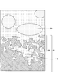
- FIG. 2 is a cross-sectional view of a surface along a reinforcing structure portion indicated by B-B ′ in FIG. 1. It is sectional drawing which shows the state which welded the exposure part and metal plate of motor vehicle parts. It is sectional drawing which shows the state which welded two motor vehicle parts by the exposed part. 2 is an SEM image of the aluminum plate surface of Example 1.
- FIG. 1 is an SEM image of the aluminum plate surface of Example 1.
- the automobile component of the present invention includes a metal plate and a reinforcing member including a thermoplastic resin disposed on one surface of the metal plate.
- the thermoplastic resin can contain reinforcing fibers such as carbon fibers and glass fibers.
- carbon fibers can be preferably used because they can provide lightweight and highly rigid automobile parts.
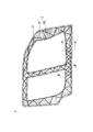
- FIG. 1 is a plan view of an automobile part of the present invention as viewed from the reinforcing member (CFRTP) side
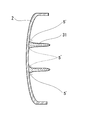
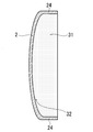
- FIG. 2 is a cross-sectional view taken along the line AA ′ in FIG.
- the automobile part 1 has a reinforcing member 3 formed of the metal plate 2 and CFRTP.
- the reinforcing member 3 has a continuous liner layer 32 that covers the metal plate 2 as well as the reinforcing structure portion 31 such as ribs and beads, and the reinforcing structure portion 31 and the reinforcing structure portion 31 standing on the liner layer 32 are reinforced.
- the space between the structural portions 31 is covered with the liner layer 32 without any gap.
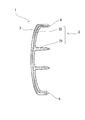
- the projected area of the liner layer 32 when the reinforcing member 3 is viewed from the thickness direction is the projected area of the entire reinforcing member 3, and as shown in FIG.
- a plurality of convex reinforcing structure portions 31 are connected and erected.
- the entire one surface of the liner layer 32 is in close contact with the metal plate 2, and the metal plate 2 and the reinforcing member 3 are directly bonded.
- the entire one surface of the liner layer 32 having a large projected area as described above is an adhesive surface, and the adhesive area between the reinforcing member 3 and the metal plate 2 is large. Therefore, the reinforcing member 3 and the metal plate 2 can be firmly bonded, and peeling can be prevented.
- the automobile part 1 has a liner layer 32 bonded to the metal plate 2, and the liner layer 32 supports the metal plate 2 at a portion where the liner layer 32 is bonded. Therefore, the thickness of the metal plate 2 can be reduced.
- the thickness of the metal plate 2 can be 0.5 mm or more and 2.5 mm or less, and the weight can be significantly reduced.
- the automobile part 1 can be manufactured by an injection press method or a press molding method.
- the injection press method after the injection material is injected with the mold slightly opened, the mold is completely closed and the injection material is pressed, and the injection material is spread over the entire cavity and molded. Is the method.
- the above injection press method can be preferably used because the molten thermoplastic resin is filled in the cavity, so that the thermoplastic resin adheres tightly to the metal plate 2 and can be firmly bonded.
- the molded metal plate is placed in the mold and pressed by the upper mold, and the injection material containing the thermoplastic resin is injected from the lower mold side toward the metal plate with the mold slightly opened. To do. Then, the mold is completely closed and the injection material is pressed together with the metal plate, the injection material is spread over the entire cavity, and a thermoplastic resin is brought into close contact with the metal plate to produce an automobile part. .
- At least one surface of the metal plate 2 is roughened. Since the adhesive surface with the reinforcing member 3 is roughened, it can be more firmly bonded.
- Examples of the roughening treatment include mechanical roughening treatment such as sand blast treatment, liquid honing treatment, buffing, polishing with a polishing sheet, acid treatment, chemical etching, and laser ridge.
- chemical etching and laser ridge can be roughened by forming a hole having an inner diameter larger than the opening diameter, unlike a mechanical surface roughening process, and a thermoplastic resin is formed in the hole by an injection press method.
- a thermoplastic resin is formed in the hole by an injection press method.
- the chemical etching can form a ant nest-like porous structure 23 in which a plurality of spaces are connected by a tunnel, as shown in FIG. 3, and a large anchor effect can be obtained and a stronger adhesion can be obtained.
- the thermoplastic resin 3 is other than the opening part. Since it can penetrate and fill the entire space of the porous structure 23 with the thermoplastic resin 3, it is particularly preferable to use it because it is difficult for filling defects to occur.
- the chemical etching can be performed by immersing the metal plate in an aqueous solution of ammonia, hydrazine and / or a water-soluble amine compound. Specifically, a metal plate can be dipped in a 3% to 10% hydrazine monohydrate aqueous solution heated to 40 ° C to 70 ° C for several minutes, and then washed with water to roughen the surface with fine irregularities. It is.
- metal plate for example, a metal plate such as aluminum, iron, stainless steel, copper, titanium, magnesium, brass, or a metal plate plated with the above metal can be used.
- the surface roughness (Ra) of the roughened metal plate is preferably 5 ⁇ m or less, more preferably 1.2 ⁇ m or less.
- the surface roughness (Ra) of the metal plate is 5 ⁇ m or less, so that even if the surface is roughened to the other surface, irregularities are not conspicuous and a design surface can be formed, and further 1.2 ⁇ m or less. A smooth painted surface can be formed.
- the thermoplastic resin preferably contains carbon fibers having an average fiber diameter of 7 ⁇ m to 15 ⁇ m and an average length of 0.1 mm to 1 mm.
- the thermoplastic resin preferably contains 30% by mass to 40% by mass of the carbon fiber.
- the carbon fiber content satisfies the above range, the rigidity of the automobile part can be improved.
- the content of the carbon fiber exceeds 40% by mass, a large amount of carbon fiber having a high thermal conductivity is included, so that the kneading material (injection material) of the thermoplastic resin and the carbon fiber is cooled and the viscosity is increased. It becomes difficult for the thermoplastic resin to enter the porous structure, causing a filling defect to easily peel off, and the rigidity of the automobile part may be lowered.
- the carbon fiber content is less than 30% by mass, the reinforcing effect of the carbon fiber is small and the rigidity of the automobile part is lowered.
- the viscosity of the injection material at the time of injection pressing is preferably 30 Pa ⁇ s or more and 200 Pa ⁇ s or less, more preferably 30 Pa ⁇ s or more and 50 Pa ⁇ s or less, although it depends on the thermoplastic resin or the injection pressure. . If the viscosity of the injection material is low, the thermoplastic resin is likely to enter the porous structure, but at a temperature of less than 30 Pa ⁇ s, the thermoplastic resin is thermally decomposed, and the adhesive strength tends to decrease.
- thermoplastic resin a thermoplastic resin that can be molded by an injection press method can be used, and examples thereof include nylon 6, nylon 66, polyphenylene sulfide, polybutylene terephthalate, and polyphthalamide.
- the projected area of the liner layer 32 is preferably 50% or more of the projected area of the metal plate 2.
- the metal plate 2 can be thinned and easily cooled, whereas the reinforcing structure portion 31 formed of CFRTP to which the metal plate 2 is bonded is thick and difficult to cool. Becomes larger. Then, a shearing force is generated due to the difference in heat shrinkage after the injection press, and the metal plate 2 is easily deformed and the metal plate 2 and the reinforcing member 3 are easily peeled off.
- the cooling rate of the metal plate 2 is reduced and the thermal strain is dispersed, so that the deformation of the metal plate 2 and the metal plate 2 Peeling from the reinforcing member 3 can be prevented. Furthermore, when the thickness of the liner layer 32 is uniform, thermal strain is reduced.
- the injection material since the injection material is injected with the mold slightly opened, the injection material leaks and the thermoplastic resin is applied outside the desired region.
- the liner layer 32 is formed continuously, and the length of the boundary 5 between the portion where the liner layer 32 shown in FIG. 2 is formed and the portion where the liner layer 32 is not formed is shown. Is shorter than the length of the boundary 5 'of the reinforcing member 3 formed by only the reinforcing structure 31 shown in FIG.
- the length of the boundary 5 is short and the risk of leakage of the thermoplastic resin is small. Therefore, injection press molding with a reduced mold seal structure for preventing leakage of the thermoplastic resin is possible. Therefore, inexpensive molding is possible.
- the projected area of the reinforcing structure portion 31 with respect to the projected area of the liner layer 32 is preferably 30% or less.
- the projected area of the reinforcing structure portion 31 is 30% or less, local deformation of the metal plate 2 that occurs in the vicinity of the reinforcing structure portion 31 due to rib contraction or the like can be prevented.
- the thickness of the liner layer 32 is preferably 1 mm or more and 3 mm or less. If it is less than 1 mm, the cavity is narrow and the filling distance is long, so that it is difficult to form by the injection press method. If it exceeds 3 mm, the effect of reducing the weight is reduced.
- the automobile part 1 preferably has a covering portion 21 covered with a liner layer 32 continuous from the one surface side at the end of the other surface of the metal plate 2. As shown in FIG. 5, by providing the liner layer 32 continuously from one surface of the metal plate 2 to the other surface, a physical fit is formed, and the CFRTP 3 can be prevented from falling off.
- the thermoplastic resin is exposed on the other surface side that is the design surface.
- it may be an automobile part that can cover the thermoplastic resin exposed in a molding such as a door frame of a body side panel. If it is, designability does not fall.
- the metal plate 2 preferably has a bent portion 24 bent toward the liner layer 32 at the end thereof.
- the strength of the metal plate 2 itself is improved by the bent portion 24, and the strength of the automobile part 1 can be improved in combination with the reinforcing member 3.
- the metal plate 2 is provided with the bent portions 24 at both ends thereof, and the cross section of the surface along the reinforcing structure portion 31 indicated by BB ′ in FIG. 1 shows the reinforcing structure as shown in FIG.
- the portion 31 is preferably erected continuously from the bent portion 24 at one end to the bent portion 24 at the other end.
- the automobile part 1 preferably has an exposed portion 22 exposed from the liner layer 32 at the end of one surface of the metal plate 2. By forming the flange and exposing it from the liner layer 32, it becomes possible to weld the metals together. As shown in FIGS. 7 and 8, another metal plate 2 ′ or another automobile part 1 ′ is further provided on the reinforcing member 3 side. And can be joined by welding.
- the bent portion 24 may include a flange portion 25 that is further bent at the end portion in the planar direction of the metal plate. Since the metal plate 2 has a hat shape having the flange portion 25, the strength of the automobile part 1 can be further improved.
- the flange portion 25 is the exposed portion 22 exposed from the liner layer 32, as shown in FIG. 8, it is joined to another metal plate 2 ′ or another automobile part 1 ′ by welding. Can do.
- the length of the exposed portion 22, that is, the length from the end of the metal plate 2 to the end of the liner layer 32 is preferably 5 mm or more and 30 mm or less.
- the length of the exposed portion 22 is less than 5 mm, not only is the welding margin small and welding is difficult, but also the thermoplastic resin is thermally decomposed by the heat of welding to generate voids in the porous structure, and the voids are separated from the origin of separation. As a result, the adhesive strength decreases. Further, when an external force is applied, stress concentrates on the boundary between the portion where the liner layer 32 is bonded and the exposed portion 22, and the reinforcing member 3 is easily peeled off.
- the liner layer 32 and the metal plate 2 are integrated to support the part. Therefore, when the length of the exposed portion 22 exceeds 30 mm and only the metal plate 2 is enlarged, The external force concentrates there and it is easy to be destroyed.
- the automobile part 1 preferably has a sandwich structure in which a reinforcing member 3 is sandwiched between metal plates 2 and 2 'as shown in FIGS.
- the end portion of the liner layer 32 of the reinforcing member 3 and the reinforcing structure portion 31 abut on the other metal plate 2 ′ or the reinforcing member 3 ′ provided on the other metal plate 2 ′ to form a hollow structure. Since the reinforcing structure portion 31 is a partition that divides the hollow structure, the automobile part 1 can be increased in strength and weight.
- the automobile part 1 can be preferably used for a door panel, a back door panel, and the like in addition to a frame member such as a body side panel, a rear fender, and a dash panel.
- Example 1 A press-molded 1 mm thick aluminum plate was immersed in an alkaline solution for degreasing, and then immersed in an acid solution for neutralization. The aluminum plate was immersed in a 5% hydrazine monohydrate aqueous solution heated to 50 ° C. for 5 minutes, then washed with water and dried to obtain an aluminum plate having a roughened surface.
- the aluminum plate is placed in a mold, and while holding the upper mold and heating to 280 ° C., the mold is slightly opened, and 35 carbon fibers having an average fiber diameter of 10 ⁇ m and an average length of 0.5 mm are obtained. A kneaded material of carbon fiber and nylon 6 containing mass% was injected. Thereafter, the mold was completely closed and pressed at 10 MPa to obtain an automobile part having a liner layer thickness of 2 mm.
- Example 2 An automobile part was obtained in the same manner as in Example 1 except that it was roughened by sandblasting and an aluminum plate having a surface roughness (Ra) of 7 ⁇ m was used.
- Example 3 An automobile part was obtained in the same manner as in Example 1 except that the aluminum plate was not roughened.
- the automobile part of the present invention has strong adhesive strength between the metal plate and the reinforcing member containing the thermoplastic resin, and can prevent peeling.
- Example 1 using a metal plate roughened by forming a hole having an inner diameter larger than the opening diameter by chemical etching is 8.4 times as large as Example 2 roughened by mechanical treatment. It has adhesive strength, and it has been confirmed that roughening by chemical etching significantly increases the adhesive strength, and that a high-rigidity automotive part can be obtained by reinforcing with a reinforcing member.
Landscapes
- Engineering & Computer Science (AREA)
- Mechanical Engineering (AREA)
- Chemical & Material Sciences (AREA)
- Combustion & Propulsion (AREA)
- Transportation (AREA)
- Architecture (AREA)
- Structural Engineering (AREA)
- Manufacturing & Machinery (AREA)
- Laminated Bodies (AREA)
- Body Structure For Vehicles (AREA)
Abstract
La présente invention concerne une pièce automobile pourvue d'un élément de renforcement qui comprend une plaque métallique et une résine thermoplastique disposée sur une surface de la plaque métallique. L'élément de renforcement présente une couche de revêtement qui recouvre la plaque métallique et une partie de structure de renforcement qui se dresse verticalement à partir de la couche de revêtement et renforce la plaque métallique. La totalité de la surface de la couche de revêtement est étroitement fixée à la plaque métallique, et la plaque métallique et l'élément de renforcement sont directement collés l'un à l'autre, une pièce automobile pouvant ainsi être prévue dans laquelle le pelage de l'élément de renforcement et de la plaque métallique est rendu impossible.
Priority Applications (5)
| Application Number | Priority Date | Filing Date | Title |
|---|---|---|---|
| CN201880093750.4A CN112203927A (zh) | 2018-05-24 | 2018-05-24 | 汽车配件 |
| PCT/JP2018/019998 WO2019224976A1 (fr) | 2018-05-24 | 2018-05-24 | Pièce automobile |
| JP2020520958A JP6997974B2 (ja) | 2018-05-24 | 2018-05-24 | 自動車部品 |
| US17/057,185 US20210188364A1 (en) | 2018-05-24 | 2018-05-24 | Automobile part |
| EP18919903.7A EP3805077B1 (fr) | 2018-05-24 | 2018-05-24 | Pièce automobile |
Applications Claiming Priority (1)
| Application Number | Priority Date | Filing Date | Title |
|---|---|---|---|
| PCT/JP2018/019998 WO2019224976A1 (fr) | 2018-05-24 | 2018-05-24 | Pièce automobile |
Publications (1)
| Publication Number | Publication Date |
|---|---|
| WO2019224976A1 true WO2019224976A1 (fr) | 2019-11-28 |
Family
ID=68615799
Family Applications (1)
| Application Number | Title | Priority Date | Filing Date |
|---|---|---|---|
| PCT/JP2018/019998 WO2019224976A1 (fr) | 2018-05-24 | 2018-05-24 | Pièce automobile |
Country Status (5)
| Country | Link |
|---|---|
| US (1) | US20210188364A1 (fr) |
| EP (1) | EP3805077B1 (fr) |
| JP (1) | JP6997974B2 (fr) |
| CN (1) | CN112203927A (fr) |
| WO (1) | WO2019224976A1 (fr) |
Citations (7)
| Publication number | Priority date | Publication date | Assignee | Title |
|---|---|---|---|---|
| JPS5523849B2 (fr) | 1972-11-10 | 1980-06-25 | ||
| JP2003502205A (ja) * | 1999-06-15 | 2003-01-21 | ローベルト ボツシユ ゲゼルシヤフト ミツト ベシユレンクテル ハフツング | シートバー |
| JP2005271477A (ja) * | 2004-03-25 | 2005-10-06 | Sharp Corp | 筐体、電子機器および複合成形方法 |
| JP2010168040A (ja) * | 2009-01-23 | 2010-08-05 | Lanxess Deutschland Gmbh | 自動車の車体構造の枠側部材 |
| WO2013029695A1 (fr) * | 2011-09-02 | 2013-03-07 | Ktm-Sportmotorcycle Ag | Carrosserie de véhicule automobile pour construction légère |
| JP2016148447A (ja) * | 2015-02-06 | 2016-08-18 | 株式会社神戸製鋼所 | 接合構造体、及び接合構造体の製造方法 |
| JP2017013430A (ja) * | 2015-07-03 | 2017-01-19 | 本田技研工業株式会社 | 樹脂製品及びその製造方法 |
Family Cites Families (12)
| Publication number | Priority date | Publication date | Assignee | Title |
|---|---|---|---|---|
| DE20013208U1 (de) * | 2000-08-01 | 2000-10-05 | Rhodia Eng Plastics Srl | Bauteil mit einem Hohlquerschnitt |
| DE10221709A1 (de) * | 2002-05-16 | 2004-03-04 | Hella-Behr Fahrzeugsysteme Gmbh | Leichtbauteil für Trägerelemente von Kraftfahrzeugen |
| DE10301520B4 (de) * | 2002-11-29 | 2012-06-21 | Lanxess Deutschland Gmbh | Kunststoff-Metall-Verbundbauteil |
| DE10317218A1 (de) * | 2003-04-15 | 2004-11-04 | Bayer Ag | Verfahren zur Herstellung eines Kunststoff-Metall-Verbundbauteils |
| DE102007038087A1 (de) * | 2007-08-11 | 2009-02-12 | GM Global Technology Operations, Inc., Detroit | Seitenwand einer Kfz-Karosserie |
| JP5802399B2 (ja) * | 2010-03-30 | 2015-10-28 | 住友化学株式会社 | 金属樹脂複合体の製造方法 |
| DE102010037459A1 (de) * | 2010-09-10 | 2012-03-15 | Dr. Ing. H.C. F. Porsche Aktiengesellschaft | Träger zur Verwendung in einem Kraftfahrzeug |
| JP5768838B2 (ja) * | 2013-06-17 | 2015-08-26 | トヨタ自動車株式会社 | 車両の骨格構造 |
| DE102013109616A1 (de) * | 2013-09-03 | 2015-03-05 | Thyssenkrupp Steel Europe Ag | Halbzeug und Verfahren zur Herstellung eines dreidimensional geformten Hybridbauteils im Metall/Kunststoffverbund sowie Verwendung eines solchen Halbzeuges |
| DE102013017269A1 (de) * | 2013-10-17 | 2014-08-28 | Daimler Ag | Karosseriebauteil und Kraftfahrzeug mit dem Karosseriebauteil |
| JP5928491B2 (ja) * | 2014-01-14 | 2016-06-01 | トヨタ自動車株式会社 | 車両の骨格構造 |
| US20160147257A1 (en) * | 2014-11-26 | 2016-05-26 | Kabushiki Kaisha Toshiba | Carbon fiber reinforced shaped product including metal plate and manufacturing method thereof |
-
2018
- 2018-05-24 WO PCT/JP2018/019998 patent/WO2019224976A1/fr unknown
- 2018-05-24 CN CN201880093750.4A patent/CN112203927A/zh active Pending
- 2018-05-24 JP JP2020520958A patent/JP6997974B2/ja active Active
- 2018-05-24 US US17/057,185 patent/US20210188364A1/en active Pending
- 2018-05-24 EP EP18919903.7A patent/EP3805077B1/fr active Active
Patent Citations (7)
| Publication number | Priority date | Publication date | Assignee | Title |
|---|---|---|---|---|
| JPS5523849B2 (fr) | 1972-11-10 | 1980-06-25 | ||
| JP2003502205A (ja) * | 1999-06-15 | 2003-01-21 | ローベルト ボツシユ ゲゼルシヤフト ミツト ベシユレンクテル ハフツング | シートバー |
| JP2005271477A (ja) * | 2004-03-25 | 2005-10-06 | Sharp Corp | 筐体、電子機器および複合成形方法 |
| JP2010168040A (ja) * | 2009-01-23 | 2010-08-05 | Lanxess Deutschland Gmbh | 自動車の車体構造の枠側部材 |
| WO2013029695A1 (fr) * | 2011-09-02 | 2013-03-07 | Ktm-Sportmotorcycle Ag | Carrosserie de véhicule automobile pour construction légère |
| JP2016148447A (ja) * | 2015-02-06 | 2016-08-18 | 株式会社神戸製鋼所 | 接合構造体、及び接合構造体の製造方法 |
| JP2017013430A (ja) * | 2015-07-03 | 2017-01-19 | 本田技研工業株式会社 | 樹脂製品及びその製造方法 |
Non-Patent Citations (1)
| Title |
|---|
| See also references of EP3805077A4 |
Also Published As
| Publication number | Publication date |
|---|---|
| US20210188364A1 (en) | 2021-06-24 |
| JPWO2019224976A1 (ja) | 2021-07-15 |
| EP3805077A4 (fr) | 2021-06-23 |
| JP6997974B2 (ja) | 2022-01-20 |
| CN112203927A (zh) | 2021-01-08 |
| EP3805077A1 (fr) | 2021-04-14 |
| EP3805077B1 (fr) | 2023-08-09 |
Similar Documents
| Publication | Publication Date | Title |
|---|---|---|
| JP7020333B2 (ja) | 車両構成部材及びその製造方法 | |
| JP5908052B2 (ja) | 異材パネル構造体 | |
| JP2004245048A (ja) | 発泡樹脂製オイルパン及びその製造方法 | |
| JP5094839B2 (ja) | アルミニウム合金複合体 | |
| JP5629835B2 (ja) | 対角支柱装置とその製造方法、及び対角支柱装置により強化された自動車の車台 | |
| CN107771124A (zh) | 包括铝板和胶粘剂芯的层合体 | |
| JP2002524304A (ja) | 接着された多層複合プレートおよび該多層複合プレートを製造する方法 | |
| JP6226724B2 (ja) | 複合成形体の製造方法及び放熱性を向上させる方法 | |
| WO2019224976A1 (fr) | Pièce automobile | |
| CN110524787B (zh) | 一种铜基合金树脂复合体的制备方法及铜基合金树脂复合体 | |
| JP7238989B2 (ja) | 金属樹脂複合体及び該金属樹脂複合体の製造方法 | |
| JPH08142110A (ja) | インモールド成形方法及び筐体 | |
| EP3995280B1 (fr) | Procédé de production de composite métal-résine | |
| JP6941285B2 (ja) | 樹脂−金属複合体を用いた部品の成形方法、および該部品成形用金型 | |
| JP2016087836A (ja) | 金属・樹脂複合材料 | |
| JP2006026912A (ja) | 基材部品および金属樹脂複合成形体および金属樹脂複合成形体の製造方法 | |
| JP2005502530A (ja) | 構造要素の製造方法 | |
| JP2021167081A (ja) | 金属樹脂複合体 | |
| JP3895168B2 (ja) | 閉空間を有する構造体の製造方法 | |
| CN112571831B (zh) | 一种橡胶-玻璃钢复合材料制品的成型方法及其制品 | |
| JP5380118B2 (ja) | 多孔質金属の取付方法 | |
| JP3277228B2 (ja) | Frp成形品のメッキ方法 | |
| JP2009148426A (ja) | 遊技機におけるガラス体 | |
| JP2019123109A (ja) | 樹脂成形品の成形方法 | |
| JP2019081508A (ja) | インストルメントパネルビーム及びこれを用いたインストルメントパネルビーム接合体 |
Legal Events
| Date | Code | Title | Description |
|---|---|---|---|
| 121 | Ep: the epo has been informed by wipo that ep was designated in this application |
Ref document number: 18919903 Country of ref document: EP Kind code of ref document: A1 |
|
| ENP | Entry into the national phase |
Ref document number: 2020520958 Country of ref document: JP Kind code of ref document: A |
|
| NENP | Non-entry into the national phase |
Ref country code: DE |
|
| ENP | Entry into the national phase |
Ref document number: 2018919903 Country of ref document: EP Effective date: 20210111 |