WO2019220748A1 - 粉粒体散布量検査装置及び検査方法、並びに粉粒体含有物品の製造装置及び製造方法 - Google Patents
粉粒体散布量検査装置及び検査方法、並びに粉粒体含有物品の製造装置及び製造方法 Download PDFInfo
- Publication number
- WO2019220748A1 WO2019220748A1 PCT/JP2019/008795 JP2019008795W WO2019220748A1 WO 2019220748 A1 WO2019220748 A1 WO 2019220748A1 JP 2019008795 W JP2019008795 W JP 2019008795W WO 2019220748 A1 WO2019220748 A1 WO 2019220748A1
- Authority
- WO
- WIPO (PCT)
- Prior art keywords
- granular material
- amount
- calibration curve
- mass
- powder
- Prior art date
- Legal status (The legal status is an assumption and is not a legal conclusion. Google has not performed a legal analysis and makes no representation as to the accuracy of the status listed.)
- Ceased
Links
Images



Classifications
-
- G—PHYSICS
- G01—MEASURING; TESTING
- G01G—WEIGHING
- G01G13/00—Weighing apparatus with automatic feed or discharge for weighing-out batches of material
- G01G13/16—Means for automatically discharging weigh receptacles under control of the weighing mechanism
-
- G—PHYSICS
- G01—MEASURING; TESTING
- G01N—INVESTIGATING OR ANALYSING MATERIALS BY DETERMINING THEIR CHEMICAL OR PHYSICAL PROPERTIES
- G01N15/00—Investigating characteristics of particles; Investigating permeability, pore-volume or surface-area of porous materials
- G01N15/02—Investigating particle size or size distribution
Definitions
- the present invention relates to an apparatus and a method for inspecting the amount of dust particles used in a step of spraying particles stored in a container onto an object to be dispersed. Moreover, this invention relates to the manufacturing apparatus and manufacturing method of a granular material containing article.
- a method for transporting and supplying powder particles stored in a container such as a hopper to the outside of the container a method of vibrating the transport path of the powder particles is known.
- the flow rate (conveyance amount per unit time) of the granular material can be adjusted by adjusting the vibration intensity of the conveyance path.
- the mass of the granular material stored in the container is continuously measured, and the change in mass per unit time (mass decrease amount) is calculated as the flow rate of the powder.
- a so-called loss-in-wait method for measuring flow rate is known.
- Patent Document 3 describes a method of measuring the mass and the like of a high-temperature granular material aggregate such as reduced iron pellets on a conveyor using an infrared or near-infrared CCD camera.
- the camera captures the difference in image density due to the temperature difference, obtains the area of the aggregate, and converts it to mass using a calibration curve.
- assembly is grasped
- Patent Document 4 describes a mass inspection apparatus for a granular material that can continuously detect the mass of the granular material constituting a product during spraying.
- this apparatus the pixel of the granular material obtained from the binarized image data at the initial stage of inspection and the mass of the granular material measured at a predetermined time by the mass measuring unit below the dropping trajectory of the granular material.
- a standard calibration curve indicating the correspondence relationship between the pixel and the mass by a linear function is created, and further, the standard calibration curve and the particle size of the granular material at the initial stage of inspection calculated from the binarized image data
- the particle size of the granular material to be inspected is calculated, and using the calculated value of the particle size, the inclination of the reference calibration curve is corrected to create a corrected calibration curve.
- the mass value of the granular material ie, the amount of dispersion
- the present invention discharges the granular material stored in the container from the container, and during the execution of the granular material spraying step of freely dropping the discharged granular material and spraying it on the object to be sprayed, It is a granular material spraying amount inspection apparatus that inspects the mass of a granular material sprayed on a spray object.
- the granular material spray amount inspection device of the present invention continuously measures the total mass of the mass of the container and the mass of the granular material in the container with a measuring means in time, and the total mass at a predetermined time t1.
- a second measuring mechanism is provided for measuring the amount of the powder particles sprayed at a certain time t2.
- the present invention discharges the granular material stored in the container from the container, and during the implementation of the granular material spraying step of freely dropping the discharged granular material and spraying it on the object to be sprayed, It is a granular material spraying amount inspection method for inspecting the mass of the granular material sprayed on the spray object.
- the method for inspecting the amount of the granular material in the present invention the total mass of the mass of the container and the mass of the granular material in the container is continuously measured with a measuring means in time, and the total mass at a predetermined time t1.
- a mass change amount measuring step for measuring the amount of change.
- diffusion amount inspection method of this invention has an imaging process process which acquires the image data by imaging the granular material which falls freely toward the said dispersion
- diffusion amount inspection method of this invention has a binarization process process which binarizes the said image data based on a predetermined threshold value, and produces
- the granular material spray amount inspection method of the present invention includes the cumulative pixel of the granular material obtained from the binarized image data accumulated at the predetermined time t1, and the mass change amount measurement step.
- the granular material spraying amount inspection method of the present invention includes a spraying amount measuring step of measuring the spraying amount of the granular material at a certain time t2 during the execution of the powdery particle spraying step based on the calibration curve. .
- the granular material stored in the container is discharged from the container, and the discharged granular material is transported in a predetermined direction by the transporting means and then freely dropped from the transporting means.
- It is a manufacturing apparatus of the granular material containing article which manufactures the article containing this granular material by implementation of the granular material spreading process spread to a spreading object.
- the apparatus for producing a granular material-containing article of the present invention measures the total mass of the mass of the container and the mass of the granular material in the container continuously in time with a measuring means, and the total at a predetermined time t1.
- a first measurement mechanism for measuring a change in mass is provided.
- the apparatus for producing a granular material-containing article of the present invention obtains image data by capturing an image of the granular material that freely falls from the conveying means toward the object to be sprayed, and obtains the image data.
- Binarization processing is performed based on a threshold value to generate and accumulate binarized image data, and the accumulated pixels of the granular material obtained from the binarized image data accumulated at the predetermined time t1, the first Based on the change amount at the predetermined time t1 measured by the measurement mechanism, a calibration curve indicating a correspondence relationship between the accumulated pixel and the change amount is created, and the powder and granular material is dispersed based on the calibration curve.
- a second measuring mechanism is provided for measuring the amount of the powder particles sprayed at a certain time t2 during the process.
- the granular material stored in the container is discharged from the container, and the discharged granular material is transported in a predetermined direction by the transporting means and then freely dropped from the transporting means.
- It is a manufacturing method of a granular material content article which manufactures an article containing this granular material by implementation of a granular material spreading process spread to a spreading object.
- the total mass of the mass of the container and the mass of the granular material in the container is continuously measured in time by a measuring means, and the total at a predetermined time t1 is measured.
- the manufacturing method of the granular material containing article of this invention has an imaging process process which captures the granular material which falls freely from the said conveyance means toward the said dispersion
- the manufacturing method of the granular material containing article of this invention has the binarization process process which produces
- the manufacturing method of the granular material containing article of this invention was measured by the cumulative pixel of the granular material obtained from the said binarized image data accumulate
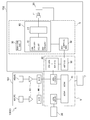
- FIG. 1 is a schematic configuration diagram of an embodiment of an apparatus for producing a granule-containing article used for carrying out the method for producing a granule-containing article of the present invention.
- FIG. 2 is a block diagram showing a control system of the manufacturing apparatus shown in FIG. 1, and is also a schematic configuration diagram of one embodiment of the granular material spray amount inspection apparatus of the present invention.
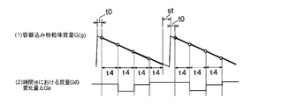
- FIG. 3 is a diagram illustrating an example of a measurement result of a control mass change amount measuring step in the method for inspecting the amount of dispersed granular material according to the present invention.
- FIG. 4 is a diagram showing an example of an algorithm for a calibration curve creation method in the method for inspecting the amount of scattered powder of the present invention.
- FIG. 5 is an example of an image obtained by imaging particles of a granular material to be inspected.
- FIG. 6 is an image obtained by binarizing the image shown in FIG.
- FIG. 7 is a graph showing an example of a calibration curve according to the present invention.
- FIG. 8A is a graph showing the change over time of the particle size variation rate of the granular material, which is calculated from the captured image data of the granular material discharged from the container and freely falling toward the object to be spread
- FIG. (B) is a graph showing the change over time of the actual measurement value of the change amount of the powdered granular material in the container at that time
- FIG. 8 (c) is a measurement of the spraying amount of the granular material calculated from the captured image data.
- FIG. 9 is a diagram showing an example of an abnormality determination step of the measuring means in the method for inspecting the amount of scattered powder of the present invention.
- FIG. 10 (a) is a graph of the change over time in the amount of spray obtained by measuring the amount of spray with a load cell type meter
- FIG. 10 (b) is the powder calculated based on the image data of the free-falling powder.
- FIG. 10C is a graph showing the change over time in the particle diameter of the body
- FIG. 10C is a graph showing the change over time obtained by measuring the amount of application using image data in Reference Example 1
- FIG. 10D is the slope of the calibration curve (calibration).
- FIG. 10E is a graph of the change over time obtained by the scattering amount measurement based on the image data in the first embodiment.
- the present invention relates to a technique capable of accurately grasping the amount of sprayed powder during spraying.
- FIG. 1 shows a schematic configuration of a production apparatus 1 which is an embodiment of the production apparatus for a granular material-containing article of the present invention.
- the manufacturing apparatus 1 discharges the granular material P stored in a hopper 2 as a container from the hopper 2, and the discharged granular material P is conveyed by a conveying means 3 to a predetermined level.
- the article containing the granular material P is manufactured by freely dropping from the conveying means 3 and then spraying on the object T to be dispersed. It can also be said to be an “apparatus”.
- Examples of the granular material-containing article manufactured by the manufacturing apparatus 1 include a heating element containing water-absorbing polymer particles as the granular material P.
- diffusion target object T a base material sheet
- the granular material P in addition to the water-absorbing polymer particles, for example, sugar, activated carbon, wheat flour, polyethylene pellets, polypropylene pellets, polyethylene terephthalate chips, polycarbonate chips, polyethylene granules, polyacrylic butyl beads and other organic particles And powders of inorganic substances such as body, metal powder, sodium chloride, potassium chloride, calcium chloride, magnesium chloride, glass and lime.
- the shape of the granular material P is not particularly limited, and examples thereof include a spherical shape, a meteorite shape, an elliptical shape, an elliptical column, a needle shape, and a cubic shape. According to the present invention, it is possible to disperse with good quantitativeness even if the granular material P has a true spherical shape, and even in a shape other than a true spherical shape.
- the manufacturing apparatus 1 includes a hopper (container) 2 that can temporarily store the powder P in the inside thereof, and the powder P discharged from the hopper 2 in one direction in a predetermined horizontal direction indicated by a symbol X in the figure.
- Conveying means 3 for conveying and spreading on a substrate sheet T (dispersion target) that is continuously conveyed is provided.
- the base sheet T can be continuously conveyed by a known conveyance device such as a conveyance roll as shown in FIG. 1 or a belt conveyor. Note that the base sheet T and its conveying device do not constitute the manufacturing apparatus 1.
- the hopper 2 has a trapezoidal shape in which the upper base is longer than the lower base when viewed from the side as shown in FIG. 1, that is, when viewed from a direction orthogonal to the conveying direction X of the powder P by the conveying means 3.
- a portion 21 and a discharge portion 22 having a rectangular parallelepiped shape connected to the lower end of the storage portion 21 and having a rectangular shape in a side view are configured.
- the storage unit 21 has a space in which the granular material P can be stored, and the granular material P can be temporarily stored in the internal space.
- the granular material P is supplied from the upper opening of the storage unit 21 to the internal space of the storage unit 21 by the granular material supply means 24.
- the discharge part 22 has a moving path for the powder P inside, and a discharge port 23 for the powder P is formed at the lower end of the discharge part 22 (the end opposite to the storage part 21 side).
- the internal space of the storage unit 21 and the discharge port 23 communicate with each other through the moving path.
- the conveying means 3 includes a receiving means (trough) 35 that receives the powder P discharged from the outlet 23 of the hopper 2 and conveys it in the horizontal direction, and is arranged on one end side of the receiving means 35. And a vibration generating means 36 for vibrating the receiving means 35 in a cantilever state.
- the conveying means 3 is arranged with a gap with respect to the discharge port 23 located at the lower end of the hopper 2.
- the vibration generating means 36 is fixed to the lower surface of the receiving means 35 (the surface opposite to the receiving surface of the powder particles P).
- the receiving means 35 is used for receiving and transporting the granular material P (in contact with the granular material P) is a portion located below the hopper 2 (discharge port 23) and its vicinity, and the others. This portion is basically a non-contact part of the granular material that does not come into contact with the granular material P.
- the vibration generating means 36 is fixed to the lower surface of the non-contact part of the granular material of the receiving means 35.
- the conveying means 3 operates the vibration generating means 36 to vibrate the receiving means 35 so that the granular material P on the receiving means 35 can be conveyed in a predetermined direction.
- the manufacturing apparatus 1 includes a control unit 5 that controls the voltage and frequency applied to the vibration generating unit 36, and the control unit 5 controls the frequency and / or amplitude of the receiving unit 35.
- the conveyance state of the granular material P on the receiving means 35 is controlled, and the spraying amount of the granular material P with respect to the base material sheet T which is a dispersion
- the vibration generating means 36 when the vibration generating means 36 is inactive, the receiving means 35 is not vibrating, so that the conveyance of the granular material P on the receiving means 35 is stopped or suppressed.
- the vibration generating means 36 When the vibration generating means 36 is operated from the state, the receiving means 35 starts to vibrate, so that the stopping or suppression of the powder P on the receiving means 35 is released.
- the base material sheet (spreading object) is finally transported below the receiving means 35 by dropping from the front end portion in the conveying direction X of the receiving means 35. ) Continuously sprayed on T.
- the receiving means 35 is preferably a flat plate from the viewpoint of appropriately transmitting the vibration generated by the vibration generating means 36 to the powder P on the receiving means 35. More specifically, FIG. A flat plate member as shown is preferred. Although the material of the receiving means 35 which consists of such a flat plate member is not restrict
- the vibration generating unit 36 may be any unit capable of generating a vibration component capable of transporting the granular material P on the receiving unit 35 in a desired direction.
- a piezoelectric element such as a piezoelectric ceramic, a vibration feeder, or the like can be used.
- a well-known vibration generating means is mentioned.
- Two measuring means 4A and 4B are attached to the hopper 2 as the measuring means 4. More specifically, as shown in FIG. 1, the weighing means 4 ⁇ / b> A is fixed to a wall portion defining the storage portion 21 of the hopper 2 via a support member 41, and another support member 42 is attached to the support member 41. The measuring means 4B is fixed via the. The support member 42 that supports the weighing means 4B is not in contact with the hopper 2 and, therefore, the mounting positions of both the weighing means 4A and 4B in the hopper 2 are the same. Note that the mounting positions and fixing methods of the weighing means 4A and 4B are not limited to the illustrated form, and can be appropriately adjusted within a range where the weighing can be accurately performed. For example, the weighing means 4A and 4B include the support members 41 and 42, respectively. You may attach directly to the wall part of the hopper 2 without going through.
- the total mass of the mass of the hopper 2 and the mass of the powder particles P in the hopper 2, that is, the mass of the hopper-containing powder particles can be continuously measured.
- measurable continuously in time means that the sampling time of the measurement data is 1 second or less.
- the total mass measurement data measured by the measurement unit 4 is transmitted to the control unit 5 every time data is acquired.
- a specific example of the measuring means 4 is an electric measuring instrument. Specifically, a load cell measuring instrument, an electromagnetic measuring instrument, a tuning fork measuring instrument, or the like can be used. Both weighing means 4A and 4B may be the same or different from each other.
- the control unit 5 controls the entire operation of the manufacturing apparatus 1 and includes a CPU, a ROM, a RAM, and the like. As shown in FIG. 1, a display unit 7 such as an image monitor is connected to the control unit 5, and data and operation signals are supplied to the control unit 5 from an input unit (not shown). The measured value of the spray amount of the granular material P is displayed.
- FIG. 2 shows a schematic configuration of the control system of the manufacturing apparatus 1.
- the control system of the manufacturing apparatus 1 shown in FIG. 2 includes the control system of the granular material spray amount inspection apparatus 100 included in the manufacturing apparatus 1.
- the granular material spraying amount inspection apparatus 100 discharges the granular material P stored in the hopper 2 from the hopper 2, and freely drops the discharged granular material P to form a base material sheet that is an object to be dispersed. It is an apparatus for inspecting the mass, that is, the spraying amount of the granular material P sprayed on the base sheet T during the execution of the granular material spraying step sprayed on T.
- the manufacturing apparatus 1 is configured to include a powder particle spray amount inspection device 100 in addition to the powder particle spray unit including the hopper 2 and the transport unit 3 as the containers described above.
- a hopper is formed by a so-called loss-in-weight type.
- coating amount with respect to the base material sheet T of the granular material P from the image data of the granular material P to perform is mentioned.
- two functions of said 1) and 2) are exhibited by the granular material spray amount inspection apparatus 100 which the manufacturing apparatus 1 comprises.
- the powder particle amount inspection apparatus 100 includes a control unit 5, a first measurement mechanism 101 mainly related to the function 1), and a second mainly related to the function 2).
- the measuring mechanism 102 is configured.
- the granular material spray amount inspection device 100 may be composed of an assembly of a plurality of devices divided for each component such as the control unit 5 and the two measurement mechanisms 101 and 102, and one device. It may consist of.
- the first measuring mechanism 101 includes a measuring unit 4 that measures the mass of the powder P in the hopper 2 together with the hopper 2.
- the first measurement mechanism 101 includes two weighing means 4A and 4B as the weighing means 4.
- the measurement result (change amount ⁇ Ga of the container-containing granular mass G) of one of these two units is used for operation control of the vibration generating unit 36 by the control unit 5, and the other measurement unit 4B.
- the measurement result (change amount ⁇ Gb of the container-containing granule mass G) is used by the second measurement mechanism 102 to create the calibration curve 40F.
- an operational amplifier circuit 43 and an A / D converter 44 are connected to both weighing means 4A and 4B, respectively, and the analog weighing signal from both weighing means 4A and 4B is amplified by the operational amplifier circuit 43. Thereafter, it is digitized by the A / D converter 44 and supplied to the control unit 5.
- the second measuring mechanism 102 is free-falling toward a part of the control unit 5 (a calibration curve creation unit 40 and a calibration curve storage area unit 50) and the base material sheet T that is a scattering object.
- the imaging unit 11 and the illumination unit 20 that are used for generating image data of the granular material P to be processed, and the image processing control unit 6 that performs image processing and the like of the image data are configured.
- the image processing control unit 6 is typically configured as a device constructed based on a computer or image controller in which image processing software or the like is installed.
- the granular material spraying amount inspection device 100 continuously measures the powder-in-mass mass G in the container by the first measuring mechanism 101 in a loss-in-weight manner, The amount of change ⁇ Ga, ⁇ Gb of the mass G at the “predetermined time” (predetermined sampling time) is measured (mass change amount measuring step). Then, in the manufacturing apparatus 1, as shown in FIG. 2, the amount of change ⁇ Ga obtained by the weighing means 4 ⁇ / b> A is used to control the spraying amount of the granular material P and to the hopper 2 under the control of the control unit 5. The control of the supply timing of the granular material P is performed. Further, the change amount ⁇ Gb obtained by the measuring means 4B is used by the second measurement mechanism 102 to create a calibration curve 40F.
- control mass change The amount of change in the powder mass G in the container used for controlling the amount of the powder P, etc.
- mass change amount for calibration curve The amount of change in the powder mass G (hereinafter also referred to as “mass change amount for calibration curve”) is different from the “predetermined time”, that is, the sampling time when measuring these.
- control cycle time the sampling time when measuring the control mass change amount
- control cycle time the sampling time when measuring the control mass change amount
- the sampling time for measuring the mass change amount for the calibration curve is also referred to as “calibration curve measurement time”, and may be denoted as “predetermined time t1” or “calibration curve measurement time t1” with reference t1. is there.
- the control mass change amount is the change amount ⁇ Ga obtained by the weighing means 4A
- the calibration curve mass change amount is the change amount ⁇ Gb obtained by the measurement means 4B. .
- the control cycle time t4 for measuring the control mass change amount is a short time from the viewpoint of promptly responding to a phenomenon in which the variable of the actual measurement value undulates (so-called hunting) due to the control operation. It is preferable that it is usually several seconds.
- the calibration curve measurement time t1 for measuring the calibration curve mass change amount is usually controlled. It is longer than the cycle time t4 and is about several seconds to several tens of seconds. However, the calibration curve measurement time t1 and the control cycle time t4 may be the same.
- FIG. 3 shows an example of a measurement result of the control mass change amount (change amount ⁇ Ga in the present embodiment).
- the manufacturing apparatus 1 discharges the granular material P stored in the hopper 2 from the discharge port 23 as shown in FIG. 3 is a loss-in-weight type, and the powdered granular material mass G is continuously measured over time, so that the measured value of the mass G can be obtained as shown in (1) of FIG. Decreases with progress.
- a lower limit value is set in advance for the powder mass G in the container, and when the measured value of the mass G reaches the lower limit value, the powder particles arranged above the hopper 2 under the control of the control unit 5.
- the powder P is replenished from the body supply means 24 (see FIG. 1).
- This replenishment of the granular material P is performed up to a predetermined upper limit value of the container-containing granular material mass G.
- the time indicated by the symbol St in (1) in FIG. 3 is the replenishment time of the granular material P, and it is preferable not to measure the mass G in the container during the replenishment time St.
- the powder particle mass G in the container matches the upper limit (the powder P is supplied from the powder supply means 24 into the hopper 2 to the predetermined upper limit).
- the discharge initial time t0 which is a fixed time after the start of discharging the body P, is unstable in discharging the powder P from the hopper 2, and therefore the amount of spraying the powder P tends not to be stable, If such a measured value of the unstable discharge initial time t0 is used for the inspection, the accuracy of the inspection result may be lowered. Therefore, the mass G is measured not only during the replenishment time St but also during the initial discharge time t0. It is preferable not to do so.
- the container-containing powder mass G is measured by the measuring means 4.
- the initial discharge time t0 is preferably 2 seconds or more, more preferably 3 seconds or more, and preferably 10 seconds or less, more preferably 5 seconds or less. From the same point of view, it is preferable to measure the mass G in the container by the measuring means 4 when the storage amount of the powder P in the hopper 2 is approximately half of the maximum storage amount of the hopper 2. . If the stored amount of the granular material P in the hopper 2 is too small, the discharge of the granular material P from the discharge port 23 becomes unstable, and the accuracy of the measured value of the container-containing granular material mass G may be lowered. .
- the powder particle amount inspection apparatus 100 continuously measures the powder content G in a container temporally by the measuring means 4A in the first measurement mechanism 101, A change amount ⁇ Ga (control mass change amount) of the mass G at a predetermined time (control cycle time) t4 is measured (control mass change amount measurement step).
- This change ⁇ Ga is defined by subtracting the mass G2 from the mass G1 (mass G1-mass G2).
- Mass G1 is the mass in the container at a certain time (starting time of one sampling time), and “Mass G2” is after time t4 has elapsed from the time (the end of the one sampling time) Time)).
- the mass G in the container typically has a sampling time (control cycle time t4) of a plurality of samples every several seconds to several tens of seconds. It is weighed by performing it continuously.
- FIG. 3 (2) shows the change ⁇ Ga in each sampling when sampling is performed a plurality of times at the predetermined time t4, that is, the change ⁇ Ga in the control cycle time t4.
- the analog weighing signals of the masses G 1 and G 2 from the weighing means 4 A are amplified by the operational amplification circuit 43 and digitally converted by the A / D converter 44.
- the change amount ⁇ Ga of the container-containing granular mass G at the control cycle time t 4 is measured from the digitized masses G 1 and G 2 in the control unit 5.
- the amount of change ⁇ Ga in the control cycle time t4 thus measured is the amount of decrease in the mass of the powder P in the hopper 2 at the control cycle time t4, that is, the hopper 2 It is equal to the discharge amount of the granular material P from.
- the discharge amount of the granular material P from the hopper 2 in the control cycle time t4 is equal to the spraying amount of the granular material P on the spray target T in the control cycle time t4.
- Control cycle time t4 in the measurement of the container-containing granular mass G when measuring the change ⁇ Ga (the control mass change), that is, “one time when measuring the mass G by sampling a plurality of times.
- the “sampling time per hit” can be arbitrarily set as appropriate.
- the control cycle time t4 may be set according to the content of the granular material P per product in the base material sheet T which is the object to be sprayed, but if the measured mass is too small, a longer time is set. do it.
- the granular material is supplied from the granular material supply means 24 from the state where the granular material P is replenished in the hopper 2 to a predetermined upper limit value. It can be set as appropriate within the time until P is supplied.
- the transfer capability of the transfer unit 3 can be changed by controlling the voltage and / or frequency applied to the vibration generating unit 36.
- a known feedback control method such as P control (proportional control), PI control or PID control can be employed.
- the coefficients in these various control methods can be determined by trial and error.
- the control of the amount of powder P the method described in Japanese Patent Application Laid-Open No. 2017-94294 related to the previous application of the present applicant can be used as appropriate.
- the granular material spray amount inspection apparatus 100 continuously measures the granular mass G in the container with time by the measuring means 4B in the first measuring mechanism 101. Then, a change amount ⁇ Gb (mass change amount for the calibration curve) of the mass G at a predetermined time (calibration curve measurement time) t1 is measured (mass change amount measurement step for the calibration curve).
- This mass change amount measuring step for measuring the change amount ⁇ Gb uses a measuring means 4B different from the measuring means 4A used for measuring the change amount ⁇ Ga, and, as described above, the sampling time (the “predetermined time”).
- the basic function of the second measuring mechanism 102 is that image data is obtained by capturing an image of the granular material P that freely falls from the conveying means 3 toward the base material sheet T that is a dispersion target. 10 W is obtained, and the image data 10 W is binarized based on a predetermined threshold value to generate and store the binarized image data 30 W, and the binarization stored at a predetermined time (calibration curve measurement time) t 1
- the calibration curve 40F indicating the correspondence between the accumulated pixel V and the change amount ⁇ G is created based on the “and the powder distribution at a certain time t2 during the execution of the granular material spraying process based on the calibration curve 40F. Calculating the amount of particle P spread It is intended.
- this “certain time t2” is also referred to as “spreading amount measurement time t2.”
- the second measuring mechanism 102 mainly performs the function of creating the calibration curve 40F from the image data 10W of the free-falling granular material P, and the granular material spraying step based on the generated calibration curve 40F.
- the former function is related to the calibration curve measurement time t1
- the latter function is related to the dispersion amount measurement time t2
- Both times t1 and t2 are generated at different timings.
- the calibration curve creation is 11W and the mass calculation is 12W, and the image data is differentiated.
- the second measurement mechanism 102 includes an imaging processing unit 10, an illumination unit 20, a binarization processing unit 30, a calibration curve creation unit 40, a calibration curve storage area unit 50, and a mass calculation unit 60.
- the basic functions are exhibited when these components 10 to 60 operate.
- the image processing control unit 6 is a portion excluding the calibration curve creation unit 40 and the calibration curve storage area unit 50, the illumination unit 20 and the imaging means 11 included in the control unit 5. is there.
- the imaging unit 11 and the illuminating unit 20 form a drop trajectory space of the granular material P that freely falls from the front end portion in the transport direction X of the receiving unit 35 in the transport unit 3. They are arranged so as to face each other in the transport direction X with being sandwiched therebetween.
- the imaging processing unit 10 includes an imaging unit 11 that captures an image of the granular material P, a storage unit 12 that stores image data of the granular material P captured by the imaging unit 11, an imaging unit 11, and And an imaging control unit 13 that controls the storage unit 12.
- distribution target object can be imaged, and it can preserve
- the image pickup means 11 various means that can pick up the free fall powder P as a still image can be employed without any particular limitation. For example, a CCD area camera or a line scan camera can be used.
- an imaging device having an imaging element in order to facilitate image processing, it is preferable to use an imaging device having an imaging element, and it is more preferable to use a line scan camera.
- the imaging device may be a charge coupled device (CCD) or a CMOS sensor.
- the image sensor is not necessarily a color image sensor, for example, an image sensor capable of expressing gradations in 256 gray scales is preferable, and an image sensor capable of expressing gradations in higher gradations is more preferable. Further, it is preferable to increase the resolution with respect to the particles to be imaged in order to obtain a clearer image.
- the storage unit 12 stores the image data 10W continuously captured by the imaging unit 11 in time series together with the imaging sampling number 10C and the imaging sampling time 10T. By counting the number of samplings 10C, it is confirmed whether each image can be captured.
- the storage unit 12 stores the binarized image data 30W generated by the binarization processing unit 30 in time series together with the number of samplings and the sampling time.
- the imaging control unit 13 performs imaging processing such as imaging speed by the imaging unit 11, control of imaging start and stop, control of writing the image data 10W and binarized image data 30W to the storage unit 12, and reading from the storage unit 12. And control related to image data. What is necessary is just to set an imaging speed suitably according to the fall speed etc. of the granular material P which falls freely.
- the illumination unit 20 has a function of illuminating a predetermined imaging area on an orbit where the imaging unit 11 picks up an image, that is, the granular material P freely falls.
- a unit that can provide sufficient brightness for imaging by the imaging processing unit 10 can be employed without any particular limitation.
- a transmission illumination system that is disposed to face the imaging unit 11 is used.
- the illumination unit 20 is preferably connected to the image processing control unit 6 (for example, the imaging control unit 13) to control the illumination intensity.
- the illumination intensity decreases and the density detected from the image data 10W decreases, the illumination intensity is increased.
- the illumination intensity increases and the density detected from the image data 10W increases, The illumination intensity can be reduced.
- the illumination method of the illumination part 20 may not be the transmission illumination method of this embodiment, for example, may be a reflection type illumination method.
- the binarization processing unit 30 is connected to the imaging processing unit 10, performs binarization processing on the image data 10 ⁇ / b> W stored in the storage unit 12, and stores the binarized image data 30 ⁇ / b> W. Generate. Specifically, a binarization threshold 30Q is set in advance, and a pixel portion having an image density (gradation) lower than the binarization threshold 30Q is set to “black” (lower limit of gradation: for example, 256 gradations). If there are 0 gradations), the region of the granular material P is shown.
- gradation image density
- the pixel portion having an image density (gradation) higher than the binarization threshold 30Q is converted to “white” (upper gradation value: for example, 255 gradations if 256 gradations), and the granular material A background area other than P is shown.
- binary image data 30W having two gradations is generated.
- the generated binarized image data 30W is written and stored in the storage unit 12 of the imaging processing unit 10 together with the imaging sampling time 10T included in the corresponding image data 10W.
- the binarization threshold 30Q can be arbitrarily set as appropriate, and can be set to a numerical value capable of accurately grasping the pixel (imaging area) of the imaged granular material P.
- the calibration curve creation data is 31W and the mass calculation data is 32W.
- the calibration curve creation unit 40 is connected to the imaging processing unit 10 as shown in FIG.
- the calibration curve creation unit 40 creates a calibration curve 40F that shows a correspondence relationship between the cumulative pixel V of the granular material P and the amount of change ⁇ G of the container-containing granular mass G as a linear function.
- the “accumulated pixel V” in the linear function is an accumulated value of the number of pixels set to “black” in the calibration image creation binary image data 31W.
- the cumulative pixel V of the linear function is the cumulative pixel of the granular material P obtained from the binarized image data 31W stored in the imaging processing unit 10 at a predetermined time (calibration curve measurement time) t1. Based on 31V.
- the “change amount ⁇ G” in the linear function is the change amount (powder body) of the container-containing powder body mass G measured by the first measurement mechanism 101 (the weighing unit 4B) at the calibration curve measurement time t1.
- the accumulated pixel 31V and the change amount ⁇ Gb are accumulated in the calibration curve creation unit 40 over the calibration curve measurement time t1 from the measurement start time.
- the calibration curve creation unit 40 calculates the weight (change amount ⁇ G / cumulative pixel V) from the accumulated pixel 31V and the change amount ⁇ Gb of the obtained granular material P.
- the weight is held in the calibration curve storage area 50 as a constant of a linear function whose calibration curve is 40F.
- the calibration curve storage area unit 50 is connected to the calibration curve creation unit 40 and stores the created calibration curve 40F.
- the mass calculation unit 60 is connected to the imaging processing unit 10 and the calibration curve storage area unit 50 as shown in FIG. From the accumulated pixel 32V of the granular material P obtained from the binarized image data 32W stored in the imaging processing unit 10 at a certain time t2 during the execution of the granular material spraying step, the mass calculation unit 60 A total mass 60G is calculated based on the calibration curve 40F.
- a time corresponding to the time during which a portion corresponding to one product of the base material sheet T that is a spraying target is conveyed (a time during which a portion corresponding to one product of the spraying target finishes passing through the spraying position of the powder P
- the total mass 60G of the granular material P is calculated.
- the “certain time (spreading amount measurement time) t2” in the mass calculator 60 can be arbitrarily set as appropriate.
- the spreading object T when the spreading object T is in the form of a long band, it is a time for spreading the powder P over a region area corresponding to one product of the moving spreading object T.
- diffusion target object T when the spreading
- FIG. 4 shows an example of an algorithm for a calibration curve creation method in the granular material spray amount inspection method performed by the granular material spray amount inspection apparatus 100 during the execution of the granular material spraying step.
- the powder particle amount inspection apparatus 100 mainly uses the measurement result (change amount ⁇ Gb of the powder particle mass G in the container) using the first measurement mechanism 101 (the weighing unit 4B).
- the second measuring mechanism 102 and the control unit 5 a method for inspecting the amount of dispersed granular material having the following steps is performed.
- the mass G in the container is continuously measured in time by the measuring means 4B, and the mass at a predetermined time (calibration curve measurement time) t1 is measured.
- G change amount ⁇ Gb is measured (mass change amount measurement step for calibration curve).
- the weighing by the weighing means 4B and the processing of the weighing data are the same as those by the weighing means 4A.
- (2) of FIG. 4 is a graph of the change over time of the amount of change ⁇ G of the powder mass G in the container (that is, the discharge amount ⁇ G of the powder P).
- the amount of change ⁇ G of each calibration curve measurement time t1 (that is, the sampling time per time) in the graph of (2) of FIG. 4 is the change with time of the powdered granular material mass G shown in (1) of FIG. In this graph, it is equal to the difference of the mass G at the time t1.
- image data 10W includes the image data 11W and 12W unless otherwise specified.
- the pixel (P) of the granular material P obtained from the image data 10W may be reduced, and the measurement accuracy of the amount of sprayed granular material P may be reduced.
- the powder that is the object to be imaged It is preferable to distribute P uniformly in a direction orthogonal to the imaging direction.
- the control unit 5 vibrates so that the particles P on the conveying unit 3 (receiving unit 35) are uniformly distributed in the direction orthogonal to the conveying direction X.
- the operation of the generating means 36 is controlled.
- the binarization processing unit 30 binarizes the image data 10 ⁇ / b> W stored in the storage unit 12 of the imaging processing unit 10 based on a predetermined threshold value, and binarized image data. 30 W is generated (binarization processing step).
- the binarized image data 30W includes calibration curve creation binarized image data 31W and mass calculation binarized image data 32W.
- the term “binarized image data 30W” includes binary image data 31W and 32W unless otherwise specified.
- FIG. 5 is a captured particle image of the granular material P, that is, image data 10W
- FIG. 6 is a binarized image of the captured particle image shown in FIG.
- the black portion indicates the powder body P.
- the size and arrangement of the black portion shown in FIG. 6 are the same as the size and arrangement of the granular material P shown in the image data 10W shown in FIG. 5, and it can be confirmed that proper binarization processing has been performed. .
- the number of pixels of the granular material can be grasped.
- the binarized image data 30W is stored in the storage unit 12 of the imaging processing unit 10 for the next reference calibration curve creation step.
- the calibration curve creation unit 40 the accumulated pixel 31V of the granular material P obtained from the binarized image data 31W accumulated for a predetermined time (calibration curve measurement time) t1, and the mass Based on the amount of change ⁇ Gb (the amount of change in mass for the calibration curve) of the powder particle mass G in the container at the predetermined time t1 measured in the amount of change measurement step, the accumulated pixel V and the amount of change of the particle P A calibration curve 40F showing the correspondence with ⁇ G is created (calibration curve creation step).
- the calibration curve 40F represented by a linear function with the weight (change amount ⁇ G / cumulative pixel V) obtained from the cumulative pixel V and the change amount ⁇ G as a constant is created.
- the accumulated pixel 31V of the granular material P based on the binarized image data 31W during the “predetermined time t1” (one sampling time) for creating a calibration curve, and the first measurement mechanism It is made based on the discharge amount ⁇ Gb of the granular material P measured by 101 (measuring means 4B).
- the calibration curve 40F corresponding to the dispersion conditions of the granular material P in the granular material distribution part comprised including the hopper 2 and the conveyance means 3 is obtained.
- the slope 1.3169 ⁇ 10 ⁇ ( ⁇ 6) of the calibration curve 40F in FIG. 7 is the weight (change amount ⁇ G / cumulative pixel V) of the calibration curve 40F.
- the calibration curve 40F is stored in the calibration curve storage area unit 50.
- the mass calculation unit 60 based on the calibration curve 40F, in the inspection process after the calibration curve 40F is created (inspection process during the execution of the granular material spraying step), a certain time
- the amount of powder P applied at t2 is measured (spraying amount measuring step).
- the total mass 60G (that is, the total mass 60G per product unit) is calculated.
- FIG. 8A is a diagram of a granular material that is obtained by capturing an image of powder particles that freely fall toward an object to be dispersed with an imaging unit in a manufacturing apparatus having the same configuration as the manufacturing apparatus 1, and calculating based on the captured image data.
- FIG. 8B is a graph showing the change over time in the particle size variation rate of the container, and FIG. 8B shows the mass of powder particles in the container at the control cycle time t4 (2.5 s) by the load cell type measuring device (measuring means) at the time of imaging.
- FIG. 8C is a graph showing the change over time of the actual measurement value of the change amount ⁇ G (the control mass change amount) of G, and FIG.
- the calibration curve 8C is calculated from the captured image data based on the calibration curve created by the procedure as described above. It is a graph which shows a time-dependent change of the measured value of the spraying amount of the granular material in the fixed time t2 (120 ms) during implementation of the said granular material spraying process.
- the spray amount of the granular material in the graph of FIG. 8 (c) is measured using a calibration curve created before the implementation of the powder and granular material spraying process, and the graph of FIG.
- the calibration curve is created only once at the first time, and the calibration curve is not updated during the powder and particle dispersion process described later.
- FIG. 8A is a relative display of the particle size at the time of measurement when the particle size of the granular material at the time of creating the calibration curve is 100%.
- the particle size of the granular material can be measured by, for example, the method described in [0039] of Patent Document 4.
- 8 (b) and FIG. 8 (c) is the relative display of the measured spray amount or the measured spray amount when the target spray amount is 100%. .
- the second measurement mechanism 102 mainly calculates the spray mass of the granular material, which is an object having a three-dimensional shape, based on the two-dimensional projection image of the particles. ing. Therefore, if the projected area of the particles does not change over the entire period of spraying the granular material, that is, if the particle diameter of the particles does not change, the correlation between the projected area and the sprayed mass is maintained. On the other hand, when the particle size of the particles changes for some reason during the spraying of the granular material, the correlation between the projected area and the sprayed mass is lost.
- the second measurement mechanism 102 performs the calibration curve creation process at predetermined time intervals during the execution of the powder and particle distribution process.
- the calibration curve 40F is updated at predetermined time intervals t3 by performing the measurement at a plurality of times, and in the spraying amount measurement step, a certain period of time (spreading amount measurement time) based on the updated calibration curve 40F each time the update is performed. ) Measure the spray amount of the granular material P at t2.
- the time points denoted by reference characters T1, T2,... (6) in FIG. 4 indicate the update timing of the calibration curve.
- the calibration curve 40F is newly created based on the accumulated pixel 31V of the granular material P and the amount of change ⁇ Gb of the container-containing granular material mass G at the time of the update.
- the calibration curve 40F before update and the calibration curve 40F after update basically differ only in the freshness of data (cumulative pixel 31V, variation ⁇ Gb) used for creating them, that is, the degree of time passage of the data.
- the creation procedure is the same as described above.
- the update of the calibration curve 40F follows, for example, the algorithm shown in FIG. (1) of FIG. 4 is a graph showing an example of a change with time of the mass G when the container-containing granule mass G is continuously measured by the measuring means 4B in the mass change measuring step.
- (2) in FIG. 4 is a change ⁇ Gb of the mass G at each predetermined time (calibration curve measurement time) t1 (that is, one sampling time) in the graph of (1) in FIG. 4 (for the calibration curve). It is a graph of a time-dependent change of (mass change amount).
- FIG. 4 shows the time-lapse of accumulated pixels 31V of the granular material P obtained from the binarized image data 31W for creating a calibration curve imaged at the same time as the measurement of (1) of FIG.
- FIG. 4 (4) is a graph of change over time of the cumulative value of the cumulative pixel 31V at each predetermined time t1 in the graph of (3) of FIG.
- the amount of change ⁇ Gb at the predetermined time t1 in the graph of (2) of FIG. 4 is divided by the cumulative pixel V at the predetermined time t1 of the graph of (4) of FIG.
- the graph of the change with time of the weight of the calibration curve 40F at the predetermined time t1 calculated by the above is shown.
- the calibration curve creation unit 40 uses the weight, that is, the slope of the updated calibration curve 40F in the ⁇ Gb / 31V graph of (5) in FIG.
- the numerical value of T1 at the time of update is adopted.
- the time from the update time T1 to the next update time T2 is based on the calibration curve 40F newly created at the update time T1.
- the amount of dust particles P sprayed at a certain time (spraying amount measurement time) t2 is measured.
- the update timing and the number of updates of the calibration curve 40F are not particularly limited, and can be set as appropriate according to the type of the granular material P, the application amount, and the like. In this way, by appropriately updating the calibration curve 40F used to calculate the amount of dispersion from the free-fall image data 10W of the particulate P, the actual amount of dispersion (change in the container-containing particulate mass G) It is possible to reduce the deviation from the amount (spreading amount measured from the amount ⁇ G), and to grasp the spraying amount more accurately.
- the data of the amount of change ⁇ Gb (the amount of change in the calibration curve mass) necessary for updating the calibration curve 40F is obtained in-line using the weighing means 4B such as a load cell type measuring instrument. When the calibration curve 40F is updated, it is not necessary to perform a calibration curve creation process that has been performed manually by a conventional worker, and high-precision measurement can be performed efficiently.
- the measuring means for measuring the powder mass G in the container may operate normally. It is a premise. If there is only one weighing means, if one of the weighing means breaks down, the weighing is possible but the measured value shows an abnormal value that does not reflect the actual condition. Since the measurement of the amount of spraying of the body is not properly performed, there is a possibility that inconveniences such as, for example, determining a defective product with an inappropriate amount of spraying of the granular material as a normal product may occur.
- the manufacturing apparatus 1 (powder particle amount inspection apparatus 100) of the present embodiment has two weighing means 4A and 4B abnormal.
- An abnormality determination mechanism for determining whether or not, and by measuring the two measurement means 4A and 4B by operating the abnormality determination mechanism under the control of the control unit 5 and performing a predetermined abnormality determination step. The values are monitored each other so that abnormalities can be grasped at an early stage. More specifically, the granular material spray amount inspection apparatus 100 of the present embodiment uses the two measuring units 4A and 4B included in the first measurement mechanism 101, respectively, for the predetermined time (calibration curve) described above.
- the powder particle amount inspection apparatus 100 includes an abnormality determination processing unit 70 that constitutes the abnormality determination mechanism.
- FIG. 9 shows an example of the abnormality determination process performed by the granular material spray amount inspection device 100.
- the measurement value of the container-containing granular material mass G by the measurement means 4A is expressed as “measurement value GA”
- the change amount of the measurement value GA at a predetermined time (calibration curve measurement time) t1 is expressed as “change amount ⁇ GbA”.
- the measurement value of the container-containing granular mass G by the measurement means 4B is expressed as “measurement value GB”
- the change amount of the measurement value GB at a predetermined time (calibration curve measurement time) t1 is expressed as “change amount ⁇ GbB”.
- the change amounts ⁇ GbA and ⁇ GbB correspond to the above-described calibration curve mass change amount ⁇ Gb, respectively, during stable dispersion of the powder P, that is, other than the replenishment time St and the discharge initial time t0 described above. Measured during the period.
- the container-containing powder mass G is continuously measured in time by the measuring means 4A, and a predetermined time (calibration curve measurement time) of the measurement value GA is measured.
- the change amount ⁇ GbA at t1 is measured (mass change amount measurement step for calibration curve).
- the powdered granular material mass G is continuously measured in time by the measuring means 4B, and the measured value GB is measured for a predetermined time (calibration curve measurement). Time) A change amount ⁇ GbB at t1 is measured (mass change amount measurement step for calibration curve). Then, in the abnormality determination processing unit 70 (see FIG.
- the manufacturing apparatus 1 has at least the weighing means 4 (4A, 4B) covered with the windshield 8 together with the hopper 2 as a container.
- the measuring means 4 is not easily affected by foreign matter such as air flow and dust, and further improvement in measurement accuracy can be expected.
- the apparatus configuration related to the control of the amount of the powder P is covered with the windshield 8, more specifically, as shown in FIG. 1, in addition to the hopper 2 and the measuring means 4,
- the conveying means 3 is also covered with a windshield 8.
- a material of the windshield 8 those conventionally used as this kind of windshield can be used without any particular limitation.
- the first measurement mechanism 101 measures the change amount ⁇ G of the container-containing powder body mass G in a loss-in-weight manner.
- the image of the granular material P which falls freely toward the base material sheet T by the 2nd measurement mechanism 102 Since the amount of spraying can be grasped from the area value of the pixel based on the data, the combination of these two kinds of measurement methods allows the particle size P to fluctuate from time to time and the overlap of the particles of the powdered material P that varies depending on the amount of spraying. It is possible to measure the spread amount with high accuracy without being affected by the above.
- the measurement by the first measurement mechanism 101 is effective for a relatively long-term measurement
- the measurement by the second measurement mechanism 102 is effective for a relatively short-term measurement.
- “measurement data of the mass of the particle” necessary for creating a calibration curve for calculating the amount of dispersion from the image data of the particle is the product manufacturing
- a dedicated mass measuring unit with a configuration in which a powder receiving tray or a calibration plate is installed in the load cell is installed below the particle dropping trajectory.
- the measurement is complicated and the productivity is increased because the product production line is stopped.
- there are problems such as concern about an increase in product defect rate due to erroneous measurement by workers.
- the manufacturing apparatus 1 (powder particle dispersal amount inspection apparatus 100), as described above, the measurement data of the mass of the granule necessary for creating the calibration curve (change in the powder mass G in the container) Since the quantity ⁇ G) is obtained in-line using the weighing means 4 such as a load cell type measuring instrument, the problem of the prior art is solved.
- the present invention is not limited to the above embodiments, and can be changed as appropriate.
- the granular material spray amount inspection device 100 of the above embodiment includes two measuring means 4A and 4B, and the operation control (vibration-containing granular material mass G of the container) is performed by one measuring means 4A. Measurement of the change amount ⁇ Ga of the container), and the change amount ⁇ Gb of the powder particle mass G contained in the container used to create the calibration curve 40F in the second measurement mechanism 102 by the other measurement means 4B.
- a single weighing unit may be used for both weighings. The following additional notes are disclosed with respect to the above-described embodiments of the present invention.
- a device for inspecting the mass of a granular material to inspect the mass of the dispersed granular material A first measuring mechanism that measures the total mass of the mass of the container and the mass of the granular material in the container continuously in time with a measuring means, and measures the amount of change in the total mass at a predetermined time t1; ,
- the granular material that freely falls toward the object to be dispersed is imaged by an imaging means to obtain image data, and the image data is binarized based on a predetermined threshold value to generate and accumulate binarized image data And based on the accumulated pixels of the granular material obtained from the binarized image data accumulated at the predetermined time t1 and the change amount at the predetermined time t1 measured by the first measurement mechanism.
- a granular material spray amount inspection device comprising a second measurement mechanism.
- the second measurement mechanism updates the calibration curve every predetermined time interval t3 during the execution of the powder and particle dispersion step, and measures the amount of powder and particles dispersed based on the updated calibration curve.
- the granular material spray amount inspection apparatus according to 1>.
- the first measuring mechanism includes two measuring means, Based on the difference between the change amount measured using one of the two weighing means and the change amount measured using the other, it is determined whether or not the measurement means is abnormal.
- the granular material spraying amount inspection device according to ⁇ 1> or ⁇ 2>, which includes an abnormality determination mechanism.
- the conveying means comprises a flat plate-like receiving means for receiving the powder discharged from the container, a vibration generating means for vibrating the receiving means, and a control unit for controlling the operation of the vibration generating means, Under the control of the control unit, by operating the vibration generating means to vibrate the receiving means, the powder on the receiving means can be conveyed in the one direction, One of the two weighing means is used for operation control of the vibration generating means by the control unit, and the other is used for creating the calibration curve by the second measuring mechanism.
- ⁇ 3> The granular material spray amount inspection apparatus according to 1.
- the said control part controls the operation
- ⁇ 6> The granular material spray amount inspection device according to any one of ⁇ 1> to ⁇ 5>, wherein at least the weighing means is covered with a windshield together with the container.
- the second measurement mechanism includes a calibration curve creation unit that creates the calibration curve,
- the calibration curve creation unit is expressed by a linear function using the weight of the calibration curve (the change amount / the cumulative pixel) as a constant from the cumulative pixel and the change amount of the granular material at the predetermined time t1.
- the granular material spray amount inspection apparatus according to any one of ⁇ 1> to ⁇ 6>, wherein the calibration curve is created.
- the second measurement mechanism includes a mass calculation unit that measures the amount of powder particles sprayed at the predetermined time t2 based on the calibration curve,
- the mass calculation unit is configured to measure the spray amount of the granular material at the predetermined time t2 by multiplying the accumulated pixel of the granular material at the predetermined time t2 by the weight of the calibration curve.
- a mass change amount measuring step of measuring a total mass of the mass of the container and the mass of the granular material in the container with a measuring means continuously in time, and measuring a change amount of the total mass at a predetermined time t1;
- An imaging processing step of obtaining image data by capturing an image of powder particles that freely fall toward the object to be sprayed, and A binarization process for generating binarized image data by binarizing the image data based on a predetermined threshold; Based on the accumulated pixel of the granular material obtained from the binarized image data accumulated at the predetermined time t1 and the change amount at the predetermined time t1 measured in the mass change amount measurement step, the accumulation A calibration
- the calibration curve is updated by performing the calibration curve creation step at every predetermined time interval t3, and in the spraying amount measurement step, the spraying amount of the granular material is measured based on the updated calibration curve.
- the mass change amount measuring step the change amount is measured using two measuring means, Based on the difference between the change amount measured using one of the two weighing means and the change amount measured using the other, it is determined whether or not the measurement means is abnormal.
- the conveying means comprises a flat plate-like receiving means for receiving the powder discharged from the container, a vibration generating means for vibrating the receiving means, and a control unit for controlling the operation of the vibration generating means, Under the control of the control unit, by operating the vibration generating means to vibrate the receiving means, the powder on the receiving means can be conveyed in the one direction, One of the two weighing means is used for controlling the operation of the vibration generating means by the control unit, and the other is used for creating the calibration curve in the calibration curve creating step.
- the granular material spray amount inspection method as described. ⁇ 13>
- the said control part controls the operation
- the calibration curve weight is expressed by a linear function with the weight of the calibration curve (the change amount / the accumulated pixel) as a constant from the accumulated pixel and the change amount of the granular material at the predetermined time t1.
- the method for inspecting the amount of spraying granular material according to any one of ⁇ 9> to ⁇ 13>, wherein the calibration curve is created.
- the spraying amount measuring step the spraying amount of the granular material at the fixed time t2 is measured by multiplying the accumulated pixel of the granular material at the fixed time t2 by the weight of the calibration curve.
- the discharged granular material is conveyed in a predetermined direction by the conveying means, and then freely dropped from the conveying means and dispersed on the object to be dispersed.
- a manufacturing apparatus of a granular material-containing article that manufactures an article including the granular body by performing the granular body spraying step,
- a first measuring mechanism that measures the total mass of the mass of the container and the mass of the granular material in the container continuously in time with a measuring means, and measures the amount of change in the total mass at a predetermined time t1;
- the granular material that freely falls from the conveying means toward the object to be dispersed is imaged by an imaging means to obtain image data, and the image data is binarized based on a predetermined threshold value to obtain binarized image data
- the accumulated pixel of the granular material obtained from the binarized image data accumulated at the predetermined time t1, and the change amount at the predetermined time t1 measured by the first measurement mechanism
- a calibration curve indicating the correspondence between the accumulated pixel and the amount of change is created, and based on the calibration curve, the powder particles are dispersed at a certain time t2 during the execution of the powder
- the second measurement mechanism updates the calibration curve at every predetermined time interval t3, and measures the amount of powder dispersed based on the updated calibration curve. Manufacturing equipment.
- the first measuring mechanism includes two measuring means, Based on the difference between the change amount measured using one of the two weighing means and the change amount measured using the other, it is determined whether or not the measurement means is abnormal.
- the conveying means comprises a flat plate-like receiving means for receiving the powder discharged from the container, a vibration generating means for vibrating the receiving means, and a control unit for controlling the operation of the vibration generating means, Under the control of the control unit, by operating the vibration generating means to vibrate the receiving means, the powder on the receiving means can be conveyed in the one direction, One of the two weighing means is used for operation control of the vibration generating means by the control unit, and the other is used for creating the calibration curve by the second measuring mechanism.
- the manufacturing apparatus of the granular material containing article as described in any one of.
- ⁇ 20> The granular material-containing article according to ⁇ 19>, wherein the control unit controls the operation of the vibration generating unit so that the granular material on the conveying unit is uniformly distributed in a direction orthogonal to the conveying direction.
- Manufacturing equipment. ⁇ 21> The apparatus for producing a granular material-containing article according to any one of ⁇ 16> to ⁇ 20>, wherein at least the weighing unit is covered with a windshield together with the container and the conveying unit.
- the second measurement mechanism includes a calibration curve creation unit that creates the calibration curve,
- the calibration curve creation unit is expressed by a linear function using the weight of the calibration curve (the change amount / the cumulative pixel) as a constant from the cumulative pixel and the change amount of the granular material at the predetermined time t1.
- the second measurement mechanism includes a mass calculation unit that measures the amount of powder particles sprayed at the predetermined time t2 based on the calibration curve,
- the mass calculation unit is configured to measure the spray amount of the granular material at the fixed time t2 by multiplying the accumulated pixel of the granular material at the fixed time t2 by the weight of the calibration curve.
- a method for producing an article containing a granular material comprising producing an article containing the granular material by performing the granular material spraying step.
- the calibration curve is updated by performing the calibration curve creation step at every predetermined time interval t3, and in the spraying amount measurement step, the spraying amount of the granular material is measured based on the updated calibration curve.
- the mass change amount measuring step the change amount is measured using two measuring means, Based on the difference between the change amount measured using one of the two weighing means and the change amount measured using the other, it is determined whether or not the measurement means is abnormal.
- the manufacturing method of the granular material containing article as described in said ⁇ 24> or ⁇ 25> which has an abnormality determination process.
- the conveying means comprises a flat plate-like receiving means for receiving the powder discharged from the container, a vibration generating means for vibrating the receiving means, and a control unit for controlling the operation of the vibration generating means, Under the control of the control unit, by operating the vibration generating means to vibrate the receiving means, the powder on the receiving means can be conveyed in the one direction, One of the two weighing means is used for controlling the operation of the vibration generating means by the controller, and the other is used for creating the calibration curve in the calibration curve creating process.
- the manufacturing method of the granular material containing article as described.
- the calibration curve weight is expressed by a linear function with the weight of the calibration curve (the change amount / the accumulated pixel) as a constant from the accumulated pixel and the change amount of the granular material at the predetermined time t1.
- the spraying amount measuring step the spraying amount of the granular material at the fixed time t2 is measured by multiplying the accumulated pixel of the granular material at the fixed time t2 by the weight of the calibration curve ⁇ 29>.
- the manufacturing method of the granular material containing article as described in any one of.
- Example 1 The granular material spray amount inspection was performed using the manufacturing apparatus for the granular material-containing article having the same configuration as that of the manufacturing apparatus 1 (the granular material spray amount inspection apparatus 100) shown in FIGS. A line scan camera was used for the imaging means 11, and line illumination was used for the illumination unit 20.
- the implementation conditions were as follows. ⁇ Powder: Sodium chloride particles (average particle size 500 ⁇ m) -Application amount: 0.094 g / cell-Calibration curve measurement time t1 (predetermined time t1): 60 sec ⁇ Spreading amount measurement time t2 (certain fixed time t2 during execution of the powder and particle scattering step): 120 msec. Calibration curve update time interval t3: 60 sec. Control cycle time t4 (predetermined time t4): 2.5 sec The “cell” means a left or right measurement window divided into two in the width direction of spreading. Here, two cells are one (one product). Under the above conditions, according to the algorithm shown in FIG.
- the method for inspecting the amount of dust particles having the mass change amount measuring step, the imaging processing step, the binarization processing step, the calibration curve creating step and the scattering amount measuring step is performed. did. Under the state where powder particles are continuously dispersed, binarized image data 31W based on the calibration curve creation image data 11W is generated, and the accumulated pixels 31V of the powder particles of the binarized image data 31W and the mass change On the basis of the change amount ⁇ Gb of the granular material mass including the hopper 2 measured by the measuring means 4 in the amount measurement step, the correspondence between the accumulated pixel V of the granular material and the change amount ⁇ G as shown in FIG.
- FIG. 10E shows a graph of the change over time in the spray amount obtained by the spray amount measurement based on the above image data.
- Example 1 The amount of sprayed particles was measured in the same manner as in Example 1 except that the calibration curve was not updated based on the accumulated pixels of the particles and the amount of change in the weight of the particles.
- FIG. 10C shows a graph of the change over time obtained by measuring the amount of application using image data.
- FIG. 10A is a graph of the change over time of the spray amount obtained by measuring the spray amount with the load cell type measuring instrument at the time of measurement in Example 1 and Reference Example 1, and FIG. It is a graph which shows the time-dependent change of the particle size of this granular material computed based on the image data of the granular material which falls freely at the time of the measurement of Reference Example 1.
- the downward arrow of the upper part of Fig.10 (a) is the timing at which the granular material was supplied to the hopper 2 from the granular material supply means 24 with reference to FIG. 1, ie, the change of the granular material to be spread. Indicates timing.
- FIG. 10A is a graph of the change over time of the spray amount obtained by measuring the spray amount with the load cell type measuring instrument at the time of measurement in Example 1 and Reference Example 1, and FIG. It is a graph which shows the time-dependent change of the particle size of this granular material computed based on the image data of the granular material which falls freely at the time
- FIG. 10D is a graph obtained by sequentially updating the slope of the calibration curve (weight of the calibration curve), and FIG. 10E is a graph of the spray amount measured based on the slope of the calibration curve in FIG. It is. 10 (a), FIG. 10 (c), and FIG. 10 (e), the scatter amount (%) on the vertical axis is the relative display of the measured scatter amount or the measured scatter amount when the target scatter amount is 100%. It is. Moreover, the particle size on the vertical axis in FIG. 10B is a relative display when the particle size of the reference salt is 100%. The calibration curve slope on the vertical axis in FIG. 10D is a relative display when the standard calibration curve is 100%.
- the particle size of the powder particles being sprayed has increased from about 10 minutes to 25 minutes after the start of measurement.
- the calibration curve is not updated at all during the measurement.
- the spraying amount obtained by the spraying amount measurement based on the image data is smaller than the target spraying amount.
- the calibration curve was updated during the measurement as shown in FIG. 10 (e)
- a result almost the same as the spraying amount obtained by the spraying amount measurement by the load cell type measuring instrument of 10 (a) was obtained. From the above, it can be seen that it is effective to appropriately update the calibration curve used in order to measure the application amount with image data with high accuracy.
- the granular material spray amount inspection apparatus and inspection method of the present invention it is possible to accurately grasp the spray amount during spraying of the granular material. Moreover, according to the manufacturing apparatus and the manufacturing method of the granular material-containing article of the present invention, the amount of spraying can be accurately grasped during the spraying of the granular material in the manufacturing process of the article. Even when the amount of spraying per minute is very small, the granular material can be sprayed with high accuracy, and the high-quality article can be manufactured stably and efficiently.
Landscapes
- Chemical & Material Sciences (AREA)
- General Physics & Mathematics (AREA)
- Physics & Mathematics (AREA)
- Biochemistry (AREA)
- Life Sciences & Earth Sciences (AREA)
- Analytical Chemistry (AREA)
- Health & Medical Sciences (AREA)
- General Health & Medical Sciences (AREA)
- Dispersion Chemistry (AREA)
- Immunology (AREA)
- Pathology (AREA)
- Filling Or Emptying Of Bunkers, Hoppers, And Tanks (AREA)
- Weight Measurement For Supplying Or Discharging Of Specified Amounts Of Material (AREA)
Abstract
製造装置(1)が具備する粉粒体散布量検査装置(100)は、容器(2)内に貯蔵されている粉粒体(P)を排出し自由落下させて散布対象物(T)に散布する、粉粒体散布工程の実施中に、粉粒体(P)の散布量を検査するもので、第1の計測機構(101)及び第2の計測機構(102)を具備する。計測機構(101)は、容器(2)と粉粒体(P)との合計質量を計量手段(4)で時間的に連続して計量し、所定時間t1における該合計質量の変化量を計測する。計測機構(102)は、自由落下する粉粒体(P)を撮像手段(11)で撮像し二値化処理して得たデータから得られる粉粒体(P)の累積画素と、計測機構(101)によって計測された該所定時間t1における前記変化量とに基づいて、検量線を作成し、該検量線に基づき、粉粒体散布工程の実施中のある一定時間t2における粉粒体(P)の散布量を計測する。
Description
本発明は、容器内に貯蔵されている粉粒体を散布対象物に散布する工程で利用される、粉粒体散布量検査装置及び検査方法に関する。また本発明は、粉粒体含有物品の製造装置及び製造方法に関する。
ホッパー等の容器に貯蔵されている粉粒体を該容器の外部に搬送・供給する方法として、粉粒体の搬送路を振動させる方法が知られている。この方法では、搬送路の振動強度を調整することで、粉粒体の流量(単位時間当たりの搬送量)を調整することができる。斯かる粉粒体の流量計測方法として、容器に貯蔵されている粉粒体の質量を連続的に計測し、単位時間当たりの質量変化(質量減少量)を算出して粉体の流量とする、いわゆるロスインウェイト方式での流量計測方法が知られている。また、粉粒体の流量を所望の値にするため、ロスインウェイト方式で算出した流量を用いて、振動強度等の駆動条件のフィードバック制御を行い、安定した一定流量を得ることが行われている(例えば特許文献1及び2)。
また、粉粒体の搬送・供給量を検査する技術に関し、検査目的に合わせて幾つかの提案がこれまでになされてきた。例えば特許文献3には、赤外線又は近赤外線CCDカメラを用いて、搬送コンベア上の還元鉄ペレット等の高温粒状物集合体の質量等を測定する方法が記載されている。この方法では、温度差による画像濃度の違いをカメラが捉え、前記集合体の面積を求め検量線により質量へ換算している。これにより、粒状物集合体の搬出元であるロータリーキルン内壁の付着物の成長状況を把握するようにしている。
特許文献4には、製品を構成する粉粒体の質量を散布中に連続検知できる粉粒体の質量検査装置が記載されている。この装置においては、検査初期段階の二値化画像データから得られる粉粒体の画素と、粉粒体の落下軌道の下方で質量測定部により所定時間に測定される粉粒体の質量とに基づいて、画素と質量との対応関係を一次関数で示す基準検量線を作成し、さらに、該基準検量線と、該二値化画像データから算出された検査初期段階の粉粒体の粒径とに基づいて、検査対象の粉粒体の粒径を算出し、その粒径の算出値を用いて、該基準検量線の傾きを補正して補正検量線を作成している。そして、撮像された各二値化画像データの画素から、前記補正検量線に基づいて、粉粒体の質量値すなわち散布量を計測している。
本発明は、容器内に貯蔵されている粉粒体を該容器から排出し、その排出された粉粒体を自由落下させて散布対象物に散布する粉粒体散布工程の実施中に、該散布対象物に散布された粉粒体の質量を検査する粉粒体散布量検査装置である。本発明の粉粒体散布量検査装置は、前記容器の質量と該容器内の粉粒体の質量との合計質量を計量手段で時間的に連続して計量し、所定時間t1における該合計質量の変化量を計測する第1の計測機構を具備する。また、本発明の粉粒体散布量検査装置は、前記散布対象物へ向けて自由落下する粉粒体を撮像手段で撮像して画像データを得、該画像データを所定の閾値に基づいて二値化処理して二値化画像データを生成・蓄積し、前記所定時間t1に蓄積された該二値化画像データから得られる該粉粒体の累積画素と、前記第1の計測機構によって計測された該所定時間t1における前記変化量とに基づいて、該累積画素と該変化量との対応関係を示す検量線を作成し、該検量線に基づき、前記粉粒体散布工程の実施中のある一定時間t2における粉粒体の散布量を計測する第2の計測機構を具備する。
また本発明は、容器内に貯蔵されている粉粒体を該容器から排出し、その排出された粉粒体を自由落下させて散布対象物に散布する粉粒体散布工程の実施中に、該散布対象物に散布された粉粒体の質量を検査する粉粒体散布量検査方法である。本発明の粉粒体散布量検査方法は、前記容器の質量と該容器内の粉粒体の質量との合計質量を計量手段で時間的に連続して計量し、所定時間t1における該合計質量の変化量を計測する質量変化量計測工程を有する。また、本発明の粉粒体散布量検査方法は、前記散布対象物へ向けて自由落下する粉粒体を撮像手段で撮像して画像データを得る撮像処理工程を有する。また、本発明の粉粒体散布量検査方法は、前記画像データを所定の閾値に基づいて二値化処理して二値化画像データを生成する二値化処理工程を有する。また、本発明の粉粒体散布量検査方法は、前記所定時間t1に蓄積された前記二値化画像データから得られる粉粒体の累積画素と、前記質量変化量計測工程で計測された該所定時間t1における前記変化量とに基づいて、該累積画素と該変化量との対応関係を示す検量線を作成する検量線作成工程を有する。また、本発明の粉粒体散布量検査方法は、前記検量線に基づき、前記粉粒体散布工程の実施中のある一定時間t2における粉粒体の散布量を計測する散布量計測工程を有する。
また本発明は、容器内に貯蔵されている粉粒体を該容器から排出し、その排出された粉粒体を搬送手段によって所定の一方向に搬送した後、該搬送手段から自由落下させて散布対象物に散布する粉粒体散布工程の実施によって、該粉粒体を含む物品を製造する、粉粒体含有物品の製造装置である。本発明の粉粒体含有物品の製造装置は、前記容器の質量と該容器内の粉粒体の質量との合計質量を計量手段で時間的に連続して計量し、所定時間t1における該合計質量の変化量を計測する第1の計測機構を具備する。また、本発明の粉粒体含有物品の製造装置は、前記搬送手段から前記散布対象物へ向けて自由落下する粉粒体を撮像手段で撮像して画像データを得、該画像データを所定の閾値に基づいて二値化処理して二値化画像データを生成・蓄積し、前記所定時間t1に蓄積された該二値化画像データから得られる該粉粒体の累積画素と、前記第1の計測機構によって計測された該所定時間t1における前記変化量とに基づいて、該累積画素と該変化量との対応関係を示す検量線を作成し、該検量線に基づき、前記粉粒体散布工程の実施中のある一定時間t2における粉粒体の散布量を計測する第2の計測機構を具備する。
また本発明は、容器内に貯蔵されている粉粒体を該容器から排出し、その排出された粉粒体を搬送手段によって所定の一方向に搬送した後、該搬送手段から自由落下させて散布対象物に散布する粉粒体散布工程の実施によって、該粉粒体を含む物品を製造する、粉粒体含有物品の製造方法である。本発明の粉粒体含有物品の製造方法は、前記容器の質量と該容器内の粉粒体の質量との合計質量を計量手段で時間的に連続して計量し、所定時間t1における該合計質量の変化量を計測する質量変化量計測工程を有する。また、本発明の粉粒体含有物品の製造方法は、前記搬送手段から前記散布対象物へ向けて自由落下する粉粒体を撮像手段で撮像して画像データを得る撮像処理工程を有する。また、本発明の粉粒体含有物品の製造方法は、前記画像データを所定の閾値に基づいて二値化処理して二値化画像データを生成する二値化処理工程を有する。また、本発明の粉粒体含有物品の製造方法は、前記所定時間t1に蓄積された前記二値化画像データから得られる粉粒体の累積画素と、前記質量変化量計測工程で計測された該所定時間t1における前記変化量とに基づいて、該累積画素と該変化量との対応関係を示す検量線を作成する検量線作成工程を有する。また、本発明の粉粒体含有物品の製造方法は、前記検量線に基づき、前記粉粒体散布工程の実施中のある一定時間t2における粉粒体の散布量を計測する散布量計測工程を有する。
特許文献1~4に記載の如き従来技術によれば、容器内に貯蔵されている粉粒体を該容器の外部に供給・搬送する場合に、粉粒体の搬送・供給量を正確に把握することができる。しかしながら近年は、このような粉粒体の質量管理に要求されるレベルが高まっており、従来技術がその高い管理要求レベルに対応するためには改善の余地がある。特に、粉粒体を含む物品を連続製造する場合、とりわけ、数ミリグラム程度の微量の粉粒体を散布して該物品を連続製造する場合に、散布中の粉粒体の質量すなわち散布量を正確に把握し得る技術は未だ提供されていない。
したがって本発明は、粉粒体の散布中にその散布量を正確に把握し得る技術に関する。
以下、本発明についてその好ましい実施形態に基づき図面を参照しながら説明する。図1には、本発明の粉粒体含有物品の製造装置の一実施形態である製造装置1の概略構成が示されている。製造装置1は、図1に示すように、容器としてのホッパー2内に貯蔵されている粉粒体Pを該ホッパー2から排出し、その排出された粉粒体Pを搬送手段3によって所定の一方向に搬送した後、該搬送手段3から自由落下させて散布対象物Tに散布することで、該粉粒体Pを含む物品を製造するもので、その主な働きから「粉粒体散布装置」とも言えるものである。
製造装置1によって製造される粉粒体含有物品としては、例えば粉粒体Pとしての吸水性ポリマー粒子を含有する発熱体が挙げられる。散布対象物Tとしては一般に基材シートが挙げられ、例えば、各種製法による不織布、樹脂フィルム、織物、編み物、紙等、及びこれらのうちの同種又は異種のものを複数枚積層した積層体等が挙げられる。
粉粒体Pとしては、吸水性ポリマー粒子の他に、例えば砂糖、活性炭、小麦粉、ポリエチレンペレット、ポリプロピレンペレット、ポリエチレンテレフタレートチップ、ポリカーボネートチップ、ポリエチレングラニュール、ポリアクリル酸ブチルビーズ等の有機物の粉粒体や、金属粉、塩化ナトリウム、塩化カリウム、塩化カルシウム、塩化マグネシウム、ガラス、石灰等の無機物の粉粒体が挙げられる。粉粒体Pの形状は特に制限されず、例えば、球状、碁石状、楕円形、楕円柱、針状、キュービック状等が挙げられる。本発明によれば、粉粒体Pが真球状の場合は勿論のこと、真球状以外の形状であっても、定量性良く散布することができる。
製造装置1は、粉粒体Pを内部に一時的に貯蔵可能なホッパー(容器)2と、ホッパー2から排出された粉粒体Pを図中符号Xで示す所定の水平方向における一方向に搬送し、連続搬送される基材シートT(散布対象物)上に散布する搬送手段3とを備えている。基材シートTは例えば、図1に示す如き搬送ロール、あるいはベルトコンベア等の公知の搬送装置により連続搬送することができる。なお、基材シートT及びその搬送装置は、製造装置1を構成するものではない。
ホッパー2は、図1に示す如き側面視、すなわち、搬送手段3による粉粒体Pの搬送方向Xと直交する方向から見た場合において、上底が下底より長い台形形状をなしている貯蔵部21と、該貯蔵部21の下端に連接され、該側面視において長方形形状をなす直方体形状の排出部22とを含んで構成されている。貯蔵部21は内部に粉粒体Pを貯蔵可能な空間を有し、その内部空間に粉粒体Pを一時的に貯蔵可能になされている。粉粒体Pは、貯蔵部21の上部開口から粉粒体供給手段24によって貯蔵部21の内部空間に供給される。排出部22は内部に粉粒体Pの移動路を有し、且つ排出部22の下端(貯蔵部21側とは反対側の端部)には、粉粒体Pの排出口23が形成されており、貯蔵部21の内部空間と排出口23とが該移動路を介して連通している。ホッパー2は、斯かる構成により、内部に一時的に貯蔵した粉粒体Pを、前記移動路を介して排出口23より排出可能になされている。
搬送手段3は、図1に示すように、ホッパー2の排出口23から排出された粉粒体Pを受け取って水平方向に搬送する受取手段(トラフ)35と、受取手段35の一端側に配されて片持ち梁の状態で該受取手段35を振動させる振動発生手段36とを含んで構成されている。搬送手段3は、ホッパー2の下端に位置する排出口23に対して隙間を置いて配置されている。振動発生手段36は、受取手段35の下面(粉粒体Pの受け取り面とは反対側の面)に固定されている。受取手段35において、粉粒体Pの受け取り及び搬送に利用される(粉粒体Pと接触する)のは、ホッパー2(排出口23)の下方に位置する部分及びその近傍であり、それ以外の部分は基本的に粉粒体Pと接触しない粉粒体非接触部であるところ、振動発生手段36は、受取手段35の該粉粒体非接触部における下面に固定されている。
搬送手段3は、振動発生手段36を作動させて受取手段35を振動させることによって、受取手段35上の粉粒体Pを所定の方向に搬送可能になされている。製造装置1は、図1に示すように、振動発生手段36に印加する電圧及び周波数を制御する制御部5を備えており、該制御部5によって、受取手段35の振動数及び/又は振幅を制御し、延いては、受取手段35上の粉粒体Pの搬送状態を制御して、散布対象物たる基材シートTに対する粉粒体Pの散布量を制御する。すなわち、制御部5による制御下、振動発生手段36の非作動時には、受取手段35は振動していないため、受取手段35上の粉粒体Pの搬送は停止又は抑制されているが、斯かる状態から振動発生手段36を作動させると、受取手段35が振動を開始することによって、受取手段35上の粉粒体Pの停止又は抑制が解除され、粉粒体Pは、図中符号Xで示す方向に搬送され、最終的には図1に示すように、受取手段35の搬送方向Xの先端部から落下して、受取手段35の下方を連続搬送されている基材シート(散布対象物)T上に連続的に散布される。
受取手段35としては、振動発生手段36によって発生する振動を受取手段35上の粉粒体Pに適切に伝えるようにする観点から、平板状のものが好ましく、より具体的には、図1に示す如き扁平な平板部材が好ましい。斯かる平板部材からなる受取手段35の材質は特に制限されないが、例えば、鉄、ステンレス、アルミニウム、プラスチック等が挙げられる。
振動発生手段36としては、受取手段35上の粉粒体Pを所望の一方向に搬送させ得る振動成分を発生可能なものであれば良く、例えば、圧電セラミック等の圧電素子、振動フィーダー等の公知の振動発生手段が挙げられる。
ホッパー2には計量手段4として、2台の計量手段4A,4Bが取り付けられている。より具体的には図1に示すように、ホッパー2の貯蔵部21を画成する壁部に支持部材41を介して計量手段4Aが固定され、また、該支持部材41に別の支持部材42を介して計量手段4Bが固定されている。計量手段4Bを支持する支持部材42はホッパー2と接触しておらず、したがって、ホッパー2における両計量手段4A,4Bの取り付け位置は同じである。なお、計量手段4A,4Bの取り付け位置や固定方法は、図示の形態に制限されず、計量が正確に行える範囲で適宜調整可能であり、例えば、計量手段4A,4Bは、支持部材41,42を介さずにホッパー2の壁部に直接取り付けられていてもよい。
計量手段4(4A,4B)としては、ホッパー2の質量と該ホッパー2内の粉粒体Pの質量との合計質量、すなわちホッパー込み粉粒体質量を時間的に連続して計量可能なものが用いられる。ここでいう、「時間的に連続して計量可能」とは、計量データのサンプリング時間が1秒以下であることをいう。計量手段4によって計量された前記合計質量の計量データは、データの取得のたびに制御部5に送信されるようになっている。計量手段4の具体例としては電気式計量器が挙げられ、具体的には、ロードセル式計量器や電磁式計量器、音叉式計量器等を用いることができる。両計量手段4A,4Bは互いに同じでもよく、異なっていてもよい。
制御部5は、製造装置1の全体の動作を制御するもので、CPU、ROM、RAMなどを含んで構成されている。図1に示すように、制御部5には画像モニタ等の表示部7が接続されており、該表示部7に、図示しない入力部からデータや操作信号が制御部5に供給されたことや、粉粒体Pの散布量の計測値等が表示されるようになされている。
図2には、製造装置1の制御系の概略構成が示されている。図2に示す製造装置1の制御系には、製造装置1が具備する粉粒体散布量検査装置100の制御系が含まれている。粉粒体散布量検査装置100は、ホッパー2内に貯蔵されている粉粒体Pを該ホッパー2から排出し、その排出された粉粒体Pを自由落下させて散布対象物たる基材シートTに散布する粉粒体散布工程の実施中に、該基材シートTに散布された粉粒体Pの質量すなわち散布量を検査する装置である。つまり製造装置1は、前述した容器としてのホッパー2と搬送手段3とを含む、粉粒体散布部に加えてさらに、粉粒体散布量検査装置100を含んで構成されている。
製造装置1の主たる特徴の1つとして、散布対象物たる基材シートTへの粉粒体Pの散布中にその散布量を適切に制御するために、1)いわゆるロスインウェイト式によって、ホッパー2の質量と該ホッパー2内の粉粒体Pの質量との合計質量(以下、「容器込み粉粒体質量」ともいう)を計測する機能と、2)基材シートTに向けて自由落下する粉粒体Pの画像データから、粉粒体Pの基材シートTに対する散布量を計測する機能とを有する点が挙げられる。そして、前記1)及び2)の2つの機能は、製造装置1が具備する粉粒体散布量検査装置100によって発揮される。
粉粒体散布量検査装置100は、図2に示すように、制御部5と、主に前記1)の機能に関わる第1の計測機構101と、主に前記2)の機能に関わる第2の計測機構102とを含んで構成されている。本発明において粉粒体散布量検査装置100は、制御部5や両計測機構101,102などの構成部ごとに分割された複数の装置の集合体からなるものであってもよく、1つの装置からなるものであってもよい。
第1の計測機構101は、図2に示すように、ホッパー2内の粉粒体Pの質量を該ホッパー2ごと計量する計量手段4を含んで構成されている。本実施形態において第1の計測機構101は、計量手段4として、2台の計量手段4A,4Bを具備している。これら2台のうちの一方の計量手段4Aによる計量結果(容器込み粉粒体質量Gの変化量△Ga)は、制御部5による振動発生手段36の動作制御に利用され、他方の計量手段4Bによる計量結果(容器込み粉粒体質量Gの変化量△Gb)は、第2の計測機構102において検量線40Fの作成に利用される。また、両計量手段4A,4Bにはそれぞれ、演算増幅回路43及びA/D変換器44が接続されており、両計量手段4A,4Bからのアナログ計量信号は、演算増幅回路43によって増幅された後、A/D変換器44によってデジタル化されて、制御部5に供給される。
第2の計測機構102は、図2に示すように、制御部5の一部(検量線作成部40、検量線記憶領域部50)と、散布対象物たる基材シートTに向けて自由落下する粉粒体Pの画像データの生成に利用される撮像手段11及び照明部20と、該画像データの画像処理等を行う画像処理制御部6とを含んで構成されている。画像処理制御部6は、典型的には、画像処理ソフトウェア等がインストールされたコンピュータや画像コントローラを基に構築した装置として構成されている。
粉粒体散布量検査装置100は、前記粉粒体散布工程の実施中に、第1の計測機構101によりロスインウェイト式で容器込み粉粒体質量Gを時間的に連続して計量し、「所定時間」(所定のサンプリング時間)における該質量Gの変化量△Ga,△Gbを計測する(質量変化量計測工程)。そして製造装置1においては、図2に示すように、計量手段4Aにより得られた変化量△Gaを用いて、制御部5による制御下で、粉粒体Pの散布量の制御やホッパー2への粉粒体Pの供給タイミングの制御などが行われる。また、計量手段4Bにより得られた変化量△Gbは、第2の計測機構102において検量線40Fの作成に利用される。
粉粒体Pの散布量の制御などに利用される容器込み粉粒体質量Gの変化量(以下、「制御用質量変化量」ともいう。)と、検量線の作成に利用される容器込み粉粒体質量Gの変化量(以下、「検量線用質量変化量」ともいう。)とは、これらを計測する際の前記「所定時間」すなわちサンプリング時間が異なる。以下では、制御用質量変化量を計測する際のサンプリング時間を「制御周期時間」ともいい、符号t4を付して、「所定時間t4」あるいは「制御周期時間t4」と表記する場合がある。また、検量線用質量変化量を計測する際のサンプリング時間を「検量線計測時間」ともいい、符号t1を付して、「所定時間t1」あるいは「検量線計測時間t1」と表記する場合がある。本実施形態では前述したとおり、制御用質量変化量は、計量手段4Aにより得られた変化量△Gaであり、検量線用質量変化量は、計量手段4Bにより得られた変化量△Gbである。
前記制御用質量変化量を計測する際の制御周期時間t4は、制御動作が原因で実測値の変数が波打つ現象(いわゆるハンチング)が生じた場合に速やかに対応するなどの観点から、短時間であることが好ましく、通常は数秒程度である。一方、正確な検量線を作成するためには計量手段による計測値が安定する時間が必要であることから、前記検量線用質量変化量を計測する際の検量線計測時間t1は、通常は制御周期時間t4よりも長く、数秒から数十秒程度である。ただし、検量線計測時間t1と制御周期時間t4とが同じになる場合もあり得る。
図3には、前記制御用質量変化量(本実施形態では変化量△Ga)の計測結果の一例が示されている。本実施形態において製造装置1は、図1に示すように、ホッパー2内に貯蔵された粉粒体Pを排出口23から排出し、その排出動作中に粉粒体散布量検査装置100(第1の計測機構101)によりロスインウェイト式で容器込み粉粒体質量Gを時間的に連続して計量するので、該質量Gの計量値は、図3の(1)に示すように時間の経過に伴って減少する。容器込み粉粒体質量Gには予め下限値が定められており、該質量Gの計量値が該下限値に達すると、制御部5による制御下で、ホッパー2の上方に配置された粉粒体供給手段24(図1参照)から粉粒体Pが補給される。この粉粒体Pの補給は、予め定められた容器込み粉粒体質量Gの上限値まで行われる。図3の(1)の符号Stで示す時間はこの粉粒体Pの補給時間であり、該補給時間St中は容器込み粉粒体質量Gの計量は行わないことが好ましい。また一般に、容器込み粉粒体質量Gが前記上限値に一致している状態(粉粒体供給手段24からホッパー2内に粉粒体Pが所定の上限値まで補給された状態)で粉粒体Pの排出を開始してからの一定時間である排出初期時間t0は、ホッパー2からの粉粒体Pの排出が安定せず、したがって粉粒体Pの散布量も安定しない傾向があり、このような散布不安定な排出初期時間t0の計量値を検査に利用すると検査結果の精度が低下するおそれがあるため、補給時間Stのみならず排出初期時間t0中も、該質量Gの計量は行わないことが好ましい。
粉粒体Pのホッパー2からの排出が安定した状態で計量を行って粉粒体Pの散布量を高精度で計測する観点から、計量手段4による容器込み粉粒体質量Gの計量を行わない排出初期時間t0は、好ましくは2秒以上、より好ましくは3秒以上、そして、好ましくは10秒以下、より好ましくは5秒以下である。
同様の観点から、計量手段4による容器込み粉粒体質量Gの計量は、ホッパー2内の粉粒体Pの貯蔵量が、該ホッパー2の最大貯蔵量の概ね半量のときに行うことが好ましい。ホッパー2内の粉粒体Pの貯蔵量が少なすぎると、排出口23からの粉粒体Pの排出が不安定となり、容器込み粉粒体質量Gの計量値の精度が低下するおそれがある。
同様の観点から、計量手段4による容器込み粉粒体質量Gの計量は、ホッパー2内の粉粒体Pの貯蔵量が、該ホッパー2の最大貯蔵量の概ね半量のときに行うことが好ましい。ホッパー2内の粉粒体Pの貯蔵量が少なすぎると、排出口23からの粉粒体Pの排出が不安定となり、容器込み粉粒体質量Gの計量値の精度が低下するおそれがある。
粉粒体散布量検査装置100は、第1の計測機構101における計量手段4Aによって、図3の(1)に示すように、容器込み粉粒体質量Gを時間的に連続して計量し、所定時間(制御周期時間)t4における該質量Gの変化量△Ga(前記制御用質量変化量)を測定する(制御用の質量変化量計測工程)。この変化量△Gaは、質量G1から質量G2を差し引くこと(質量G1-質量G2)で定義される。「質量G1」は、ある時刻(1回のサンプリング時間の開始時刻)での容器込み粉粒体質量であり、「質量G2」は、該時刻から時間t4経過後(該1つのサンプリング時間の終了時刻)の容器込み粉粒体質量である。変化量△Ga(前記制御用質量変化量)を測定する場合の容器込み粉粒体質量Gは、典型的には、サンプリング時間(制御周期時間t4)が数秒から数十秒毎のサンプリングを複数回連続して行うことにより計量される。図3の(2)には、所定時間t4で複数回サンプリングした場合の各サンプリングにおける変化量△Ga、すなわち制御周期時間t4における変化量△Gaが示されている。
具体的には図2に示すように、第1の計測機構101において、計量手段4Aからの質量G1,G2のアナログ計量信号が、演算増幅回路43によって増幅され、A/D変換器44によってデジタル化されて制御部5に供給され、制御部5においてこのデジタル化された質量G1,G2から、制御周期時間t4における容器込み粉粒体質量Gの変化量△Gaが測定される。ここで、ホッパー2の質量は不変であるから、こうして測定された制御周期時間t4における変化量△Gaは、制御周期時間t4におけるホッパー2内の粉粒体Pの質量の減少量、すなわちホッパー2からの粉粒体Pの排出量に等しい。また、斯かる制御周期時間t4におけるホッパー2からの粉粒体Pの排出量は、該制御周期時間t4における散布対象物Tへの粉粒体Pの散布量に等しい。
変化量△Ga(前記制御用質量変化量)を測定する場合の容器込み粉粒体質量Gの測定における制御周期時間t4、すなわち、「複数回のサンプリングによって該質量Gを測定する場合の1回当たりのサンプリング時間」は適宜任意に設定できる。制御周期時間t4は、散布対象物たる基材シートTにおける1製品当たりの粉粒体Pの含有量に合わせて設定してもよいが、測定質量が小さすぎる場合は、それより長い時間を設定すればよい。例えば、1製品毎(1秒以下の周期)では質量値が小さく測定できない場合、ホッパー2内に粉粒体Pが所定の上限値まで補給された状態から粉粒体供給手段24より粉粒体Pが供給されるまでの時間内で適宜設定することができる。
制御部5は、第1の計測機構101の計量手段4Aによって計測された、制御周期時間t4における容器込み粉粒体質量Gの変化量(粉粒体Pのホッパー2からの排出量)△Ga」に基づいて、粉粒体Pの質量減少速度(排出速度)Dr(=△Ga/t4)を算出し、算出された質量減少速度Drに応じて、搬送手段3の搬送能力を制御し、該搬送手段3によって基材シートT上に散布される粉粒体Pの単位時間当たりの散布量ΔSを、予め設定された単位時間当たりの目標散布量ΔStに一致させる搬送能力制御操作を行う。搬送能力制御操作においては、例えばDrがΔStよりも少ない場合には、搬送手段3の搬送能力を高めて散布量ΔSを増加させる操作を行う。逆に、DrがΔStよりも多い場合には、搬送手段3の搬送能力を低めて散布量ΔSを減少させる操作を行う。搬送手段3の搬送能力は、前述したように、振動発生手段36に印加する電圧及び/又は周波数を制御することで変更が可能である。振動発生手段36の制御には、例えばP制御(比例制御)、PI制御又はPID制御などの公知のフィードバック制御方法を採用することができる。これらの各種の制御方法における係数は、トライアル・アンド・エラーによって決定することができる。粉粒体Pの散布量の制御については、本出願人の先の出願に係る特開2017-94294号公報に記載の方法を適宜利用することもできる。
また、粉粒体散布量検査装置100は、第1の計測機構101における計量手段4Bによって、図4の(1)に示すように、容器込み粉粒体質量Gを時間的に連続して計量し、所定時間(検量線計測時間)t1における該質量Gの変化量△Gb(前記検量線用質量変化量)を測定する(検量線用の質量変化量計測工程)。この変化量△Gb測定用の質量変化量計測工程は、変化量△Gaの測定に用いた計量手段4Aとは別の計量手段4Bを用いる点、及び前述したようにサンプリング時間(前記「所定時間」)が異なる点以外は、基本的に、前述した変化量△Ga測定用の質量変化量計測工程(制御用の質量変化量計測工程)と同じであり、特に断らない限り、変化量△Ga測定用の質量変化量計測工程についての説明が適宜適用される。第1の計測機構101によって計測された△Gbは、第2の計測機構102において検量線40Fの作成に利用される。
第2の計測機構102の基本機能は、図2に示すように、搬送手段3から散布対象物たる基材シートTへ向けて自由落下する粉粒体Pを撮像手段11で撮像して画像データ10Wを得、該画像データ10Wを所定の閾値に基づいて二値化処理して二値化画像データ30Wを生成・蓄積し、所定時間(検量線計測時間)t1に蓄積された該二値化画像データ30Wから得られる「粉粒体Pの累積画素V」と、第1の計測機構101における計量手段4Bによって計測された該所定時間t1における「容器込み粉粒体質量Gの変化量△Gb」とに基づいて、累積画素Vと変化量△Gとの対応関係を示す検量線40Fを作成し、該検量線40Fに基づき、前記粉粒体散布工程の実施中のある一定時間t2における粉粒体Pの散布量を算出するというものである。以下、この「一定時間t2」を「散布量計測時間t2」ともいう。このように、第2の計測機構102は主に、自由落下する粉粒体Pの画像データ10Wから検量線40Fを作成する機能と、作成した検量線40Fに基づいて前記粉粒体散布工程の実施中すなわちリアルタイムでの粉粒体Pの散布量を算出する機能とを有し、前者の機能に関わるのが検量線計測時間t1、後者の機能に関わるのが散布量計測時間t2であり、両時間t1,t2はその発生するタイミングが互いに異なる。なお、本明細書において、画像データ10Wのうち、検量線作成用のものを11W、質量演算用のものを12Wとして、区別して表記する場合がある。
第2の計測機構102は、図2に示すように、撮像処理部10、照明部20、二値化処理部30、検量線作成部40、検量線記憶領域部50及び質量演算部60を有し、これら構成部10~60が動作することで前記基本機能が発揮される。これらの各構成部10~60のうち、制御部5が備える検量線作成部40及び検量線記憶領域部50と、照明部20及び撮像手段11とを除いた部分が、画像処理制御部6である。本実施形態においては、撮像手段11及び照明部20は、図1に示すように、搬送手段3における受取手段35の搬送方向Xの先端部から自由落下する、粉粒体Pの落下軌道空間を間に挟んで、該搬送方向Xにおいて相対向するように配置されている。
撮像処理部10は、図2に示すように、粉粒体Pを撮像する撮像手段11と、撮像手段11が撮像した粉粒体Pの画像データを保存する保存部12と、撮像手段11及び保存部12を制御する撮像制御部13とを有する。これにより、散布対象物たる基材シートTへ向けて自由落下する粉粒体Pを撮像し、画像データ10Wとして保存することができる。
撮像手段11としては、自由落下する粉粒体Pを静止画像として撮像できる種々の手段を特に制限なく採用できる。例えば、CCD方式のエリアカメラやラインスキャンカメラなどが挙げられる。特に、画像処理しやすくするために、撮像素子を有する撮像装置を用いることが好ましく、ラインスキャンカメラを用いることがより好ましい。撮像素子としては、電荷結合素子(CCD)であってもCMOSセンサであってもよい。撮像素子は、必ずしもカラー撮像素子である必要はなく、例えば256階調のグレースケールでの階調表現ができる撮像素子が好ましく、さらに高階調な階調表現ができる撮像素子がより好ましい。また、撮像する粒子に対する分解能を上げることが、より鮮明な画像を得るために好ましい。
撮像手段11としては、自由落下する粉粒体Pを静止画像として撮像できる種々の手段を特に制限なく採用できる。例えば、CCD方式のエリアカメラやラインスキャンカメラなどが挙げられる。特に、画像処理しやすくするために、撮像素子を有する撮像装置を用いることが好ましく、ラインスキャンカメラを用いることがより好ましい。撮像素子としては、電荷結合素子(CCD)であってもCMOSセンサであってもよい。撮像素子は、必ずしもカラー撮像素子である必要はなく、例えば256階調のグレースケールでの階調表現ができる撮像素子が好ましく、さらに高階調な階調表現ができる撮像素子がより好ましい。また、撮像する粒子に対する分解能を上げることが、より鮮明な画像を得るために好ましい。
保存部12は、撮像手段11で連続的に撮像された画像データ10Wを、その撮像サンプリング数10C及び撮像サンプリング時間10Tとともに時系列で保存する。サンプリング数10Cをカウントすることにより1枚1枚撮像できているか確認する。また、保存部12は、二値化処理部30で生成された二値化画像データ30Wを、サンプリング数及びサンプリング時間とともに時系列で保存する。
撮像制御部13は、撮像手段11による撮像スピード、撮像開始及び停止の制御、画像データ10W及び二値化画像データ30Wの保存部12への書き込み及び保存部12からの読み出しの制御など、撮像処理及び画像データに関する制御を行う。撮像スピードは、自由落下する粉粒体Pの落下スピード等に合わせて適宜設定すればよい。
撮像制御部13は、撮像手段11による撮像スピード、撮像開始及び停止の制御、画像データ10W及び二値化画像データ30Wの保存部12への書き込み及び保存部12からの読み出しの制御など、撮像処理及び画像データに関する制御を行う。撮像スピードは、自由落下する粉粒体Pの落下スピード等に合わせて適宜設定すればよい。
照明部20は、撮像手段11で撮像される撮像領域、すなわち粉粒体Pが自由落下する軌道上の所定の撮像領域を照らす機能を備える。照明部20としては、撮像処理部10による撮像に十分な明るさを提供できるものを特に制限なく採用できる。本実施形態では図1に示すように、撮像手段11に対向配置される透過照明方式が用いられている。照明部20は、画像処理制御部6(例えば撮像制御部13)に接続され、照明強度を制御するようにすることが好ましい。これにより、照明の照度が下がり、画像データ10Wから検出される濃度が下がった際に、照明強度を上げ、反対に照明の照度が上がり、画像データ10Wから検出される濃度が上がった際に、照明強度を下げることができる。また、照明部20の照明方式は、本実施形態の透過照明方式でなくともよく、例えば反射型照明方式であってもよい。
二値化処理部30は、図2に示すように、撮像処理部10に接続されており、保存部12に保存された画像データ10Wの二値化処理を行い、二値化画像データ30Wを生成する。具体的には、二値化閾値30Qを予め設定しておき、二値化閾値30Qよりも画像濃度(階調)の低い画素部分を「黒」(階調の下限値:例えば256階調であれば0階調)に変換して粉粒体Pの領域を示す。一方、前記二値化閾値30Qよりも画像濃度(階調)の高い画素部分を「白」(階調の上限値:例えば256階調であれば255階調)に変換して、粉粒体P以外の背景領域を示す。このようにして、二階調からなる二値化画像データ30Wが生成される。生成された二値化画像データ30Wは、対応する画像データ10Wが有する撮像サンプリング時間10Tとともに、撮像処理部10の保存部12に書き込まれ保存される。前記の二値化閾値30Qは、適宜任意に設定でき、撮像された粉粒体Pの画素(撮像面積)を的確に把握できる数値に設定することができる。なお、本明細書において、二値化画像データ30Wのうち、検量線作成用のものを31W、質量演算用のものを32Wとして、区別して表記する場合がある。
検量線作成部40は、図2に示すように、撮像処理部10に接続されている。検量線作成部40は、粉粒体Pの累積画素Vと容器込み粉粒体質量Gの変化量△Gとの対応関係を一次関数で示す検量線40Fを作成する。前記一次関数における「累積画素V」は、検量線作成用二値化画像データ31Wで「黒」とされた画素数の累積値のことである。検量線40Fの作成に際し、前記一次関数の累積画素Vは、所定時間(検量線計測時間)t1に撮像処理部10に保存される二値化画像データ31Wから得られる粉粒体Pの累積画素31Vに基づく。また、前記一次関数における「変化量△G」は、第1の計測機構101(計量手段4B)によって計測された、検量線計測時間t1における容器込み粉粒体質量Gの変化量(粉粒体Pのホッパー2からの排出量)△Gb(前記検量線用質量変化量)に基づく。累積画素31V及び変化量△Gbは、それぞれ、計測開始時点から検量線計測時間t1にわたって検量線作成部40に蓄積される。検量線計測時間t1経過後、検量線作成部40において、得られた粉粒体Pの累積画素31V及び変化量△Gbから、重み(変化量△G/累積画素V)を算出する。その重みが検量線40Fである一次関数の定数として検量線記憶領域部50に保持される。検量線記憶領域部50は、検量線作成部40に接続されており、作成された検量線40Fを保存する。
質量演算部60は、図2に示すように、撮像処理部10及び検量線記憶領域部50に接続されている。質量演算部60は、前記粉粒体散布工程の実施中のある一定の時間t2に撮像処理部10に保存される二値化画像データ32Wから得られる、粉粒体Pの累積画素32Vから、検量線40Fに基づいて総質量60Gを算出する。具体的には、散布対象物たる基材シートTの1製品に相当する部分が搬送される時間分(散布対象物の1製品に相当する部分が粉粒体Pの散布位置を通過し終わる時間分)の粉粒体Pの累積画素32Vに、検量線記憶領域部50に保存されている検量線40Fの重み(変化量△G/累積画素V)を乗算することにより、1製品単位当たりの粉粒体Pの総質量60Gを算出する。質量演算部60における「一定の時間(散布量計測時間)t2」は適宜任意に設定できる。例えば、散布対象物Tが長尺帯状である場合は、移動中の散布対象物Tの1製品に相当する領域面積に対して粉粒体Pを散布する時間である。また、散布対象物Tが製品単位に既に区分けされて間欠的に搬送される場合は、間隔をあけて移動中の散布対象物Tの面積に対して粉粒体Pを散布する時間である。例えば、300個/分の製品搬送速度ならばt2=60/300=200ms(ミリ秒)、400個/分の速度ならばt2=60/400=150ms(ミリ秒)となる。
図4には、前記粉粒体散布工程の実施中に粉粒体散布量検査装置100が実施する、粉粒体散布量検査方法における検量線作成方法のアルゴリズムの一例が示されている。粉粒体散布量検査装置100は、図4に示すアルゴリズムに従い、第1の計測機構101(計量手段4B)による計量結果(容器込み粉粒体質量Gの変化量△Gb)を用い、主として第2の計測機構102と制御部5との協働により、以下の工程を有する粉粒体散布量検査方法を実施する。
先ず、図4の(1)~(2)に示すように、容器込み粉粒体質量Gを計量手段4Bで時間的に連続して計量し、所定時間(検量線計測時間)t1における該質量Gの変化量△Gbを計測する(検量線用の質量変化量計測工程)。計量手段4Bによる計量及びその計量データの処理は、前述したとおり、計量手段4Aによるものと同じである。図4の(2)は、容器込み粉粒体質量Gの変化量△G(すなわち粉粒体Pの排出量△G)の経時変化のグラフである。図4の(2)のグラフにおける、各検量線計測時間t1(すなわち1回当たりのサンプリング時間)の変化量△Gは、図4の(1)に示す容器込み粉粒体質量Gの経時変化のグラフにおいて、当該時間t1における該質量Gの差分に等しい。
次いで、散布対象物たる基材シートTへ向けて自由落下する粉粒体Pを撮像手段11で撮像して画像データ10Wを得る(撮像処理工程)。撮像処理工程により、図2に示すように、画像データ10Wとして、検量線作成用画像データ11W及び質量演算用画像データ12Wが、その撮像サンプリング時間10Tとともに時系列で保存部12に保存される。以下、「画像データ10W」と言うときには、特に断らない限り、画像データ11W,12Wが含まれる。
撮像手段11で撮像した画像データ10Wにおいて、被撮像体である粉粒体Pの分布が不均一で粒子どうしの重なり部分が多数存在すると、該画像データ10Wから得られる粉粒体Pの画素(面積値)と該画像データ10Wの撮像時に実際に存在していた粉粒体Pの質量との相関性が低下し、粉粒体Pの散布量の計測精度が低下するおそれがある。そこで、画像データ10Wにおける粒子どうしの重なりを低減して散布量の計測精度の向上を図る観点から、自由落下する粉粒体Pを撮像手段11で撮像する場合、被撮像体である粉粒体Pを撮像方向と直交する方向において均一に分布させることが好ましい。本実施形態においては、斯かる粉粒体Pの自由落下時の均一分布を実現するため、図1に示すように、搬送手段3における受取手段35の搬送方向Xの先端部から自由落下する粉粒体Pを撮像手段11で撮像する場合において、制御部5は、搬送手段3(受取手段35)上の粉粒体Pがその搬送方向Xと直交する方向において均一に分布するように、振動発生手段36の動作を制御する。このように、自由落下する直前の粉粒体Pの分布を均一にしておくことで、自由落下時の分布も均一になりやすくなる。
次いで、図2に示すように、二値化処理部30において、撮像処理部10の保存部12に保存された画像データ10Wを所定の閾値に基づいて二値化処理して二値化画像データ30Wを生成する(二値化処理工程)。この二値化画像データ30Wには、検量線作成用二値化画像データ31Wと、質量演算用二値化画像データ32Wとが含まれる。以下、「二値化画像データ30W」と言うときには、特に断らない限り、二値化画像データ31W,32Wが含まれる。
二値化処理工程においては、二値化閾値30Qを境に0階調と1階調とに変換する。図5は、撮像した粉粒体Pの粒子画像、すなわち画像データ10Wであり、図6は、図5に示す撮像した粒子画像の二値化画像である。図6において黒色部分が粉粒体Pを示している。図6に示す黒色部分の大きさや配置は、図5に示す画像データ10Wに写った粉粒体Pの大きさや配置と一致しており、適正な二値化処理がなされていることが確認できる。この二値化画像データ30Wから粉粒体の画素数を把握できる。二値化画像データ30Wは、次の基準検量線作成工程のため、撮像処理部10の保存部12に保存される。
次いで、図2に示すように、検量線作成部40において、所定時間(検量線計測時間)t1に蓄積された二値化画像データ31Wから得られる粉粒体Pの累積画素31Vと、前記質量変化量計測工程で計測された該所定時間t1における容器込み粉粒体質量Gの変化量△Gb(前記検量線用質量変化量)とに基づいて、粉粒体Pの累積画素Vと変化量△Gとの対応関係を示す検量線40Fを作成する(検量線作成工程)。ここでは、前述のとおり、累積画素Vと変化量△Gとから得られた重み(変化量△G/累積画素V)を定数とする一次関数で表される検量線40Fを作成する。これは、検量線作成のための「所定時間t1」(1回当たりのサンプリング時間)の間の、二値化画像データ31Wに基づいて粉粒体Pの累積画素31Vと、第1の計測機構101(計量手段4B)によって計測された粉粒体Pの排出量△Gbとに基づいてなされる。これにより、ホッパー2及び搬送手段3を含んで構成される粉粒体散布部における、粉粒体Pの散布条件に対応した検量線40Fが得られる。図7には、検量線40Fの一例が示されている。図7中の検量線40Fの傾き1.3169×10^(-6)が、該検量線40Fの重み(変化量△G/累積画素V)である。検量線作成工程においては、この検量線40Fを検量線記憶領域部50に保存する。
次いで、図2に示すように、質量演算部60において、検量線40Fに基づき、検量線40Fの作成後の検査処理(前記粉粒体散布工程の実施中における検査処理)において、ある一定の時間t2における粉粒体Pの散布量を計測する(散布量計測工程)。具体的には前述のとおり、質量演算のための「一定の時間t2」の間に、質量演算用二値化画像データ32Wに基づいて粉粒体Pの累積画素32Vから、検量線40Fに基づいて、総質量60G(すなわち1製品単位当たりの総質量60G)を算出する。
前述した、第2の計測機構102による画像データに基づく粉粒体Pの散布量の計測方法によれば、連続的に散布される粉粒体Pの経時的な粒径変動に起因して、粉粒体散布量の画像による計測値が実際の散布量とは無関係に経時的に変動するという課題に対しても、的確に散布量を計測することができる。この画像による散布量計測に特有の課題について、図8を参照して以下に説明する。
図8(a)は、製造装置1と同様の構成の製造装置において、散布対象物に向けて自由落下する粉粒体を撮像手段で撮像し、その撮像画像データに基づき算出した該粉粒体の粒径変動率の経時変化を示すグラフ、図8(b)は、斯かる撮像時におけるロードセル式計量器(計量手段)による、制御周期時間t4(2.5s)における容器込み粉粒体質量Gの変化量△G(前記制御用質量変化量)の実測値の経時変化を示すグラフ、図8(c)は、前述の如き手順で作成された検量線に基づき該撮像画像データから算出された、前記粉粒体散布工程の実施中のある一定時間t2(120ms)における粉粒体の散布量の計測値の経時変化を示すグラフである。ただし、図8(c)のグラフにおける粉粒体の散布量は、前記粉粒体散布工程の実施前に作成した検量線を用いて計測されたものであり、図8(c)のグラフを作成するに際しては、検量線の作成はこの初回の1回限りであり、後述する前記粉粒体散布工程中の検量線の更新は行っていない。なお、図8(a)における粉粒体の粒径変動率(%)は、検量線作成時の粉粒体の粒径を100%としたときの計測時の該粒径の相対表示である。粉粒体の粒径は、例えば特許文献4の[0039]に記載の方法により測定することができる。また、図8(b)及び図8(c)における縦軸の粉粒体の散布量(%)は、目標散布量を100%としたときの実測散布量又は計測散布量の相対表示である。図8(a)~図8(c)の3つのグラフの対比から明らかなように、図8(b)のいわゆるロスインウェイト式の計測結果では、実測散布量が一定の比較的狭い幅で変動していて、粉粒体の単位時間当たりの散布量が安定しているのに対し、図8(c)の画像データによる計測結果では、図8(a)の粒径変動率の経時的な増加傾向に連動して、経時的な減少傾向が認められる。つまり、実際には粉粒体の散布量が安定していて問題ない状態であるにもかかわらず、画像による散布量計測では、図8(c)に示す如き散布量が安定していないという結果が示されるおそれがあるということである。
粉粒体散布量検査装置100においては、前述したとおり主に第2の計測機構102により、三次元形状を有する物体である粉粒体の散布質量を、粒子の二次元投影像に基づき算出している。したがって、粉粒体の散布の全期間にわたり粒子の投影面積が不変であれば、すなわち粒子の粒径が不変であれば、投影面積と散布質量との相関関係が維持される。一方、粉粒体の散布中に何らかの原因によって粒子の粒径が変化した場合には、投影面積と散布質量との相関関係が崩れてしまう。例えば、検量線作成時の粒子の半径をdとし、粒径変動率をα(=d’/d)と定義した場合、変動後の粒径はd’=αdとなる。したがって、粒径の変動の前後での面積比S’/Sは、πd’2/πd2=(αd)2/d2=α2となる。また、粒径の変動の前後での体積比V’/Vは、{(π/6)d’3}/{(π/6)d3}=(αd)3/d3=α3となる。したがって、粒径変動率αが例えば1.1の場合、つまり粒径が10%増加した場合には、面積比S’/Sは1.21となり、体積比V’/Vは1.33となる。すなわちΔ=V’/V-S’/Sで定義される誤差が12%となる。要するに、粉粒体の粒径が10%増加した場合には、検量線から算出される散布質量に12%の誤差が生じることになる。この現象は、同質量の粉粒体を散布しているにもかかわらず、粒径変動率αが1を超えると、撮像処理によって取得される二値化画像データの面積が相対的に小さくなり(画素数が少なくなり)、実際よりも少量の粉粒体が散布されていると誤認されてしまうこと、及び粒径変動率αが1を下回ると、撮像処理によって取得される二値化画像データの面積が相対的に大きくなり(画素数が多くなり)、実際よりも多量の粉粒体が散布されていると誤認されてしまうことに起因している。
そこで、前述した画像による散布量計測の課題を解決するために、本実施形態において第2の計測機構102は、前記粉粒体散布工程の実施中に、前記検量線作成工程を所定時間間隔毎に複数回実施することで検量線40Fを所定時間t3間隔毎に更新し、前記散布量計測工程においてはその更新の度に、更新された検量線40Fに基づき、ある一定時間(散布量計測時間)t2における粉粒体Pの散布量を計測する。図4の(6)の符号T1,T2・・・が付された時点は、それぞれ、検量線の更新タイミングを示している。検量線40Fの更新時には、その更新時における粉粒体Pの累積画素31Vと容器込み粉粒体質量Gの変化量△Gbとに基づいて、検量線40Fを改めて作成する。更新前の検量線40Fと更新後の検量線40Fとは、基本的にそれらの作成に使用するデータ(累積画素31V、変化量△Gb)の鮮度、すなわち該データの時間経過の度合いが異なるだけであり、作成手順は前述のとおりで互いに同じである。
検量線40Fの更新は、例えば図4に示すアルゴリズムに従う。図4の(1)は、前記質量変化量計測工程において容器込み粉粒体質量Gを計量手段4Bで時間的に連続して計量した際の該質量Gの経時変化の一例を示すグラフであり、図4の(2)は、図4の(1)のグラフの各所定時間(検量線計測時間)t1(すなわち1回のサンプリング時間)における該質量Gの変化量△Gb(前記検量線用質量変化量)の経時変化のグラフである。また、図4の(3)は、図4の(1)の計量と同時期に撮像された検量線作成用二値化画像データ31Wから得られた、粉粒体Pの累積画素31Vの経時変化のグラフであり、図4の(4)は、図4の(3)のグラフの各所定時間t1における累積画素31Vの累積値の経時変化のグラフである。また、図4の(5)には、図4の(2)のグラフの所定時間t1における変化量△Gbを、図4の(4)のグラフの該所定時間t1における累積画素Vで除することによって算出された、所定時間t1における検量線40Fの重みの経時変化のグラフが示されている。
例えば、図4中符号T1で示す検量線40Fの更新時には、検量線作成部40において、その更新後の検量線40Fの重みすなわち傾きとして、図4の(5)の△Gb/31Vのグラフにおける更新時T1の数値が採用される。そして、質量演算部60による前記散布量計測工程においては、その更新時T1から次回の更新時T2までの時間(更新時間間隔t3)は、更新時T1で改めて作成された検量線40Fに基づき、ある一定時間(散布量計測時間)t2における粉粒体Pの散布量を計測する。検量線40Fの更新のタイミング、更新回数は特に制限されず、粉粒体Pの種類や散布量などに応じて適宜設定することができる。このように、粉粒体Pの自由落下の画像データ10Wからその散布量を算出するのに使用する検量線40Fを適宜更新することで、実際の散布量(容器込み粉粒体質量Gの変化量△Gから計測される散布量)との乖離を小さくすることが可能となり、散布量をより一層正確に把握することが可能となる。また、本実施形態においては、検量線40Fの更新に必要な変化量△Gb(前記検量線用質量変化量)のデータを、ロードセル式計量器の如き計量手段4Bを用いてインラインで取得するため、検量線40Fの更新時に、従来作業員の手作業で行われていた検量線作成処理を行う必要がなく、高精度の計測を効率良く行うことができる。
ところで、前述した粉粒体散布量検査装置100による粉粒体散布量検査方法が所定の効果を発現するためには、容器込み粉粒体質量Gを計量する計量手段が正常に動作することが前提となる。仮に計量手段が1台しかない場合、その1台の計量手段が故障するなどして、計量は可能であるが計量値が実態を反映していない異常値を示す状態となった場合、粉粒体の散布量の計測が適切になされないため、例えば、粉粒体散布量が適切ではない不良品を正常品と判断してしまうなどの不都合が生じるおそれがある。
このような計量手段の異常に起因する不都合を未然に防止するため、本実施形態の製造装置1(粉粒体散布量検査装置100)は、2台の計量手段4A,4Bが異常であるか否かを判定する異常判定機構を具備しており、制御部5による制御下で該異常判定機構を作動させて所定の異常判定工程を実施することで、2台の計量手段4A,4Bの計量値を相互に監視し、異常を早期に把握できるようになされている。より具体的には、本実施形態の粉粒体散布量検査装置100は、第1の計測機構101が具備する2台の計量手段4A,4Bをそれぞれ用いて、前述した、所定時間(検量線計測時間)t1における容器込み粉粒体質量Gの変化量△Gbを計測し、それらの計測値の誤差に基づいて計量手段4A,4Bの異常を判定する。粉粒体散布量検査装置100は、図2に示すように、前記異常判定機構を構成する異常判定処理部70を有している。
図9には、粉粒体散布量検査装置100が実施する前記異常判定工程の一例が示されている。以下では、容器込み粉粒体質量Gの計量手段4Aによる計量値を「計量値GA」、所定時間(検量線計測時間)t1における該計量値GAの変化量を「変化量△GbA」と表記する。また、容器込み粉粒体質量Gの計量手段4Bによる計量値を「計量値GB」、所定時間(検量線計測時間)t1における該計量値GBの変化量を「変化量△GbB」と表記する。変化量△GbA,△GbBは、それぞれ、前述した検量線用質量変化量△Gbに相当するものであり、粉粒体Pの安定散布中、すなわち前述した補給時間St及び排出初期時間t0以外の期間中に計測される。
先ず、図9の(1)~(2)に示すように、容器込み粉粒体質量Gを計量手段4Aで時間的に連続して計量し、その計量値GAの所定時間(検量線計測時間)t1における変化量△GbAを計測する(検量線用の質量変化量計測工程)。同様に、図9の(3)~(4)に示すように、容器込み粉粒体質量Gを計量手段4Bで時間的に連続して計量し、その計量値GBの所定時間(検量線計測時間)t1における変化量△GbBを計測する(検量線用の質量変化量計測工程)。そして、制御部5による制御下で異常判定処理部70(図2参照)において、図9の(5)に示すように、変化量△GbAと変化量△GbBとの差(△GbA-△GbB)を算出し、その差(変化量誤差)が、予め設定された基準範囲に収まっている場合(例えば変化量誤差が1%以内の場合)は「異常なし」、該基準範囲から外れている場合(例えば変化量誤差が1%を超える場合)は「異常あり」と判定する(異常判定工程)。このような異常判定工程によれば、2台の計量手段4A,4Bの計量値を相互に監視可能になされているため、計量手段の異常に起因する不都合を効果的に防止することができ、計量手段の点検頻度の減少、生産性の向上が期待できる。
また、製造装置1(粉粒体散布量検査装置100)は、図1に示すように、少なくとも計量手段4(4A,4B)が、容器としてのホッパー2とともに風防8で覆われているため、計量手段4が空気の流動や埃などの異物の影響を受けにくく、計測精度の一層の向上が期待できる。本実施形態においては、粉粒体Pの散布量の制御に関わる装置構成が風防8で覆われており、具体的には図1に示すように、ホッパー2及び計量手段4に加えてさらに、搬送手段3も風防8で覆われている。風防8の素材としては、この種の風防として従来使用されている物を特に制限無く用いることができる。
前述の如き構成の製造装置1(粉粒体散布量検査装置100)によれば、第1の計測機構101により、ロスインウェイト式で容器込み粉粒体質量Gの変化量△Gを計測することで、散布対象物たる基材シートTに対する粉粒体Pの散布量を迅速に把握できるとともに、第2の計測機構102により、基材シートTに向けて自由落下する粉粒体Pの画像データに基づく画素の面積値からも該散布量を把握できるため、これら2種類の計測方法の組み合わせにより、随時変動する粉粒体Pの径変動や散布量によって異なる粉粒体Pの粒子の重なりにも影響されず、該散布量の計測を高精度で行うことができる。特に、第1の計測機構101による計測は、比較的長期間の計測に有効であり、第2の計測機構102による計測は、比較的短期間の計測に有効である。
また従来、製造装置1の如き粉粒体散布装置において、粉粒体の画像データから散布量を算出するための検量線の作成に必要な「粉粒体の質量の計測データ」は、製品製造ラインが稼働していない状態で、粉粒体の落下軌道の下方に、ロードセルに粉粒体受け皿又は検量皿を設置した構成の専用の質量測定部を設置し、該質量測定部で落下した粉粒体の質量を作業員が計測することで取得されていたところ(例えば特許文献4の[0038]参照)、斯かる計測は作業が煩雑な上、製品製造ラインを止めて行うために生産性の低下を招き、さらには作業員の誤計測による製品不良率の上昇が懸念されるなどの課題があった。これに対し、製造装置1(粉粒体散布量検査装置100)によれば、前述したように、検量線作成に必要な粉粒体の質量の計測データ(容器込み粉粒体質量Gの変化量△G)は、ロードセル式計量器の如き計量手段4を用いてインラインで取得するため、従来技術の課題が解消される。
以上、本発明の実施態様について説明したが、本発明は前記実施態様に制限されず、適宜変更可能である。
例えば、前記実施形態の粉粒体散布量検査装置100は、2台の計量手段4A,4Bを具備し、一方の計量手段4Aによって、振動発生手段36の動作制御(容器込み粉粒体質量Gの変化量△Gaの計測)のための計量を行い、他方の計量手段4Bによって、第2の計測機構102における検量線40Fの作成に利用される容器込み粉粒体質量Gの変化量△Gbの計測のための計量を行っていたが、1台の計量手段で双方の計量を兼務するように構成してもよい。前述した本発明の実施態様に関し、さらに以下の付記を開示する。
例えば、前記実施形態の粉粒体散布量検査装置100は、2台の計量手段4A,4Bを具備し、一方の計量手段4Aによって、振動発生手段36の動作制御(容器込み粉粒体質量Gの変化量△Gaの計測)のための計量を行い、他方の計量手段4Bによって、第2の計測機構102における検量線40Fの作成に利用される容器込み粉粒体質量Gの変化量△Gbの計測のための計量を行っていたが、1台の計量手段で双方の計量を兼務するように構成してもよい。前述した本発明の実施態様に関し、さらに以下の付記を開示する。
<1>
容器内に貯蔵されている粉粒体を該容器から排出し、その排出された粉粒体を自由落下させて散布対象物に散布する粉粒体散布工程の実施中に、該散布対象物に散布された粉粒体の質量を検査する粉粒体散布量検査装置であって、
前記容器の質量と該容器内の粉粒体の質量との合計質量を計量手段で時間的に連続して計量し、所定時間t1における該合計質量の変化量を計測する第1の計測機構と、
前記散布対象物へ向けて自由落下する粉粒体を撮像手段で撮像して画像データを得、該画像データを所定の閾値に基づいて二値化処理して二値化画像データを生成・蓄積し、前記所定時間t1に蓄積された該二値化画像データから得られる該粉粒体の累積画素と、前記第1の計測機構によって計測された該所定時間t1における前記変化量とに基づいて、該累積画素と該変化量との対応関係を示す検量線を作成し、該検量線に基づき、前記粉粒体散布工程の実施中のある一定時間t2における粉粒体の散布量を計測する第2の計測機構とを具備する粉粒体散布量検査装置。
容器内に貯蔵されている粉粒体を該容器から排出し、その排出された粉粒体を自由落下させて散布対象物に散布する粉粒体散布工程の実施中に、該散布対象物に散布された粉粒体の質量を検査する粉粒体散布量検査装置であって、
前記容器の質量と該容器内の粉粒体の質量との合計質量を計量手段で時間的に連続して計量し、所定時間t1における該合計質量の変化量を計測する第1の計測機構と、
前記散布対象物へ向けて自由落下する粉粒体を撮像手段で撮像して画像データを得、該画像データを所定の閾値に基づいて二値化処理して二値化画像データを生成・蓄積し、前記所定時間t1に蓄積された該二値化画像データから得られる該粉粒体の累積画素と、前記第1の計測機構によって計測された該所定時間t1における前記変化量とに基づいて、該累積画素と該変化量との対応関係を示す検量線を作成し、該検量線に基づき、前記粉粒体散布工程の実施中のある一定時間t2における粉粒体の散布量を計測する第2の計測機構とを具備する粉粒体散布量検査装置。
<2>
前記第2の計測機構は、前記粉粒体散布工程の実施中に前記検量線を所定時間間隔t3毎に更新し、更新された検量線に基づき、粉粒体の散布量を計測する前記<1>に記載の粉粒体散布量検査装置。
<3>
前記第1の計測機構は、前記計量手段を2台具備し、
前記2台の計量手段のうちの一方を用いて計測された前記変化量と他方を用いて計測された前記変化量との差に基づいて、当該計量手段が異常であるか否かを判定する異常判定機構を具備する前記<1>又は<2>に記載の粉粒体散布量検査装置。
<4>
前記粉粒体散布工程においては、前記容器から排出された粉粒体が、搬送手段によって所定の一方向に搬送された後、該搬送手段から自由落下して散布対象物に散布されるようになされており、
前記搬送手段は、前記容器から排出された粉粒体を受け取る平板状の受取手段と、該受取手段を振動させる振動発生手段と、該振動発生手段の動作を制御する制御部とを具備し、該制御部による制御下で、該振動発生手段を作動させて該受取手段を振動させることによって、該受取手段上の粉粒体を前記一方向に搬送可能になされており、
前記2台の計量手段のうちの一方が、前記制御部による前記振動発生手段の動作制御に利用され、他方が、前記第2の計測機構による前記検量線の作成に利用される前記<3>に記載の粉粒体散布量検査装置。
<5>
前記制御部は、前記搬送手段上の粉粒体がその搬送方向と直交する方向において均一に分布するように、前記振動発生手段の動作を制御する前記<4>に記載の粉粒体散布量検査装置。
<6>
少なくとも前記計量手段が、前記容器とともに風防で覆われている前記<1>~<5>のいずれか1に記載の粉粒体散布量検査装置。
<7>
前記第2の計測機構は、前記検量線を作成する検量線作成部を具備し、
前記検量線作成部は、前記所定時間t1における前記粉粒体の累積画素と前記変化量とから、前記検量線の重み(該変化量/該累積画素)を定数とする一次関数で表される前記検量線を作成する前記<1>~<6>のいずれか1に記載の粉粒体散布量検査装置。
<8>
前記第2の計測機構は、前記検量線に基づき前記一定時間t2における粉粒体の散布量を計測する質量演算部を具備し、
前記質量演算部は、前記一定時間t2における前記粉粒体の累積画素に前記検量線の重みを乗算することにより、該一定時間t2における粉粒体の散布量を計測する前記<7>に記載の粉粒体散布量検査装置。
前記第2の計測機構は、前記粉粒体散布工程の実施中に前記検量線を所定時間間隔t3毎に更新し、更新された検量線に基づき、粉粒体の散布量を計測する前記<1>に記載の粉粒体散布量検査装置。
<3>
前記第1の計測機構は、前記計量手段を2台具備し、
前記2台の計量手段のうちの一方を用いて計測された前記変化量と他方を用いて計測された前記変化量との差に基づいて、当該計量手段が異常であるか否かを判定する異常判定機構を具備する前記<1>又は<2>に記載の粉粒体散布量検査装置。
<4>
前記粉粒体散布工程においては、前記容器から排出された粉粒体が、搬送手段によって所定の一方向に搬送された後、該搬送手段から自由落下して散布対象物に散布されるようになされており、
前記搬送手段は、前記容器から排出された粉粒体を受け取る平板状の受取手段と、該受取手段を振動させる振動発生手段と、該振動発生手段の動作を制御する制御部とを具備し、該制御部による制御下で、該振動発生手段を作動させて該受取手段を振動させることによって、該受取手段上の粉粒体を前記一方向に搬送可能になされており、
前記2台の計量手段のうちの一方が、前記制御部による前記振動発生手段の動作制御に利用され、他方が、前記第2の計測機構による前記検量線の作成に利用される前記<3>に記載の粉粒体散布量検査装置。
<5>
前記制御部は、前記搬送手段上の粉粒体がその搬送方向と直交する方向において均一に分布するように、前記振動発生手段の動作を制御する前記<4>に記載の粉粒体散布量検査装置。
<6>
少なくとも前記計量手段が、前記容器とともに風防で覆われている前記<1>~<5>のいずれか1に記載の粉粒体散布量検査装置。
<7>
前記第2の計測機構は、前記検量線を作成する検量線作成部を具備し、
前記検量線作成部は、前記所定時間t1における前記粉粒体の累積画素と前記変化量とから、前記検量線の重み(該変化量/該累積画素)を定数とする一次関数で表される前記検量線を作成する前記<1>~<6>のいずれか1に記載の粉粒体散布量検査装置。
<8>
前記第2の計測機構は、前記検量線に基づき前記一定時間t2における粉粒体の散布量を計測する質量演算部を具備し、
前記質量演算部は、前記一定時間t2における前記粉粒体の累積画素に前記検量線の重みを乗算することにより、該一定時間t2における粉粒体の散布量を計測する前記<7>に記載の粉粒体散布量検査装置。
<9>
容器内に貯蔵されている粉粒体を該容器から排出し、その排出された粉粒体を自由落下させて散布対象物に散布する粉粒体散布工程の実施中に、該散布対象物に散布された粉粒体の質量を検査する粉粒体散布量検査方法であって、
前記容器の質量と該容器内の粉粒体の質量との合計質量を計量手段で時間的に連続して計量し、所定時間t1における該合計質量の変化量を計測する質量変化量計測工程と、
前記散布対象物へ向けて自由落下する粉粒体を撮像手段で撮像して画像データを得る撮像処理工程と、
前記画像データを所定の閾値に基づいて二値化処理して二値化画像データを生成する二値化処理工程と、
前記所定時間t1に蓄積された前記二値化画像データから得られる粉粒体の累積画素と、前記質量変化量計測工程で計測された該所定時間t1における前記変化量とに基づいて、該累積画素と該変化量との対応関係を示す検量線を作成する検量線作成工程と、
前記検量線に基づき、前記粉粒体散布工程の実施中のある一定時間t2における粉粒体の散布量を計測する散布量計測工程とを有する粉粒体散布量検査方法。
容器内に貯蔵されている粉粒体を該容器から排出し、その排出された粉粒体を自由落下させて散布対象物に散布する粉粒体散布工程の実施中に、該散布対象物に散布された粉粒体の質量を検査する粉粒体散布量検査方法であって、
前記容器の質量と該容器内の粉粒体の質量との合計質量を計量手段で時間的に連続して計量し、所定時間t1における該合計質量の変化量を計測する質量変化量計測工程と、
前記散布対象物へ向けて自由落下する粉粒体を撮像手段で撮像して画像データを得る撮像処理工程と、
前記画像データを所定の閾値に基づいて二値化処理して二値化画像データを生成する二値化処理工程と、
前記所定時間t1に蓄積された前記二値化画像データから得られる粉粒体の累積画素と、前記質量変化量計測工程で計測された該所定時間t1における前記変化量とに基づいて、該累積画素と該変化量との対応関係を示す検量線を作成する検量線作成工程と、
前記検量線に基づき、前記粉粒体散布工程の実施中のある一定時間t2における粉粒体の散布量を計測する散布量計測工程とを有する粉粒体散布量検査方法。
<10>
前記検量線作成工程を所定時間間隔t3毎に実施することで前記検量線を更新し、前記散布量計測工程においては、更新された検量線に基づき、粉粒体の散布量を計測する前記<9>に記載の粉粒体散布量検査方法。
<11>
前記質量変化量計測工程においては、2台の前記計量手段を用いて前記変化量を計測し、
前記2台の計量手段のうちの一方を用いて計測された前記変化量と他方を用いて計測された前記変化量との差に基づいて、当該計量手段が異常であるか否かを判定する異常判定工程を有する前記<9>又は<10>に記載の粉粒体散布量検査方法。
<12>
前記粉粒体散布工程においては、前記容器から排出された粉粒体が、搬送手段によって所定の一方向に搬送された後、該搬送手段から自由落下して散布対象物に散布されるようになされており、
前記搬送手段は、前記容器から排出された粉粒体を受け取る平板状の受取手段と、該受取手段を振動させる振動発生手段と、該振動発生手段の動作を制御する制御部とを具備し、該制御部による制御下で、該振動発生手段を作動させて該受取手段を振動させることによって、該受取手段上の粉粒体を前記一方向に搬送可能になされており、
前記2台の計量手段のうちの一方が、前記制御部による前記振動発生手段の動作制御に利用され、他方が、前記検量線作成工程において前記検量線の作成に利用される前記<11>に記載の粉粒体散布量検査方法。
<13>
前記制御部は、前記搬送手段上の粉粒体がその搬送方向と直交する方向において均一に分布するように、前記振動発生手段の動作を制御する前記<12>に記載の粉粒体散布量検査方法。
<14>
前記検量線作成工程においては、前記所定時間t1における前記粉粒体の累積画素と前記変化量とから、前記検量線の重み(該変化量/該累積画素)を定数とする一次関数で表される前記検量線を作成する前記<9>~<13>のいずれか1に記載の粉粒体散布量検査方法。
<15>
前記散布量計測工程においては、前記一定時間t2における前記粉粒体の累積画素に前記検量線の重みを乗算することにより、該一定時間t2における粉粒体の散布量を計測する前記<14>に記載の粉粒体散布量検査方法。
前記検量線作成工程を所定時間間隔t3毎に実施することで前記検量線を更新し、前記散布量計測工程においては、更新された検量線に基づき、粉粒体の散布量を計測する前記<9>に記載の粉粒体散布量検査方法。
<11>
前記質量変化量計測工程においては、2台の前記計量手段を用いて前記変化量を計測し、
前記2台の計量手段のうちの一方を用いて計測された前記変化量と他方を用いて計測された前記変化量との差に基づいて、当該計量手段が異常であるか否かを判定する異常判定工程を有する前記<9>又は<10>に記載の粉粒体散布量検査方法。
<12>
前記粉粒体散布工程においては、前記容器から排出された粉粒体が、搬送手段によって所定の一方向に搬送された後、該搬送手段から自由落下して散布対象物に散布されるようになされており、
前記搬送手段は、前記容器から排出された粉粒体を受け取る平板状の受取手段と、該受取手段を振動させる振動発生手段と、該振動発生手段の動作を制御する制御部とを具備し、該制御部による制御下で、該振動発生手段を作動させて該受取手段を振動させることによって、該受取手段上の粉粒体を前記一方向に搬送可能になされており、
前記2台の計量手段のうちの一方が、前記制御部による前記振動発生手段の動作制御に利用され、他方が、前記検量線作成工程において前記検量線の作成に利用される前記<11>に記載の粉粒体散布量検査方法。
<13>
前記制御部は、前記搬送手段上の粉粒体がその搬送方向と直交する方向において均一に分布するように、前記振動発生手段の動作を制御する前記<12>に記載の粉粒体散布量検査方法。
<14>
前記検量線作成工程においては、前記所定時間t1における前記粉粒体の累積画素と前記変化量とから、前記検量線の重み(該変化量/該累積画素)を定数とする一次関数で表される前記検量線を作成する前記<9>~<13>のいずれか1に記載の粉粒体散布量検査方法。
<15>
前記散布量計測工程においては、前記一定時間t2における前記粉粒体の累積画素に前記検量線の重みを乗算することにより、該一定時間t2における粉粒体の散布量を計測する前記<14>に記載の粉粒体散布量検査方法。
<16>
容器内に貯蔵されている粉粒体を該容器から排出し、その排出された粉粒体を搬送手段によって所定の一方向に搬送した後、該搬送手段から自由落下させて散布対象物に散布する粉粒体散布工程の実施によって、該粉粒体を含む物品を製造する、粉粒体含有物品の製造装置であって、
前記容器の質量と該容器内の粉粒体の質量との合計質量を計量手段で時間的に連続して計量し、所定時間t1における該合計質量の変化量を計測する第1の計測機構と、
前記搬送手段から前記散布対象物へ向けて自由落下する粉粒体を撮像手段で撮像して画像データを得、該画像データを所定の閾値に基づいて二値化処理して二値化画像データを生成・蓄積し、前記所定時間t1に蓄積された該二値化画像データから得られる該粉粒体の累積画素と、前記第1の計測機構によって計測された該所定時間t1における前記変化量とに基づいて、該累積画素と該変化量との対応関係を示す検量線を作成し、該検量線に基づき、前記粉粒体散布工程の実施中のある一定時間t2における粉粒体の散布量を計測する第2の計測機構とを具備する粉粒体含有物品の製造装置。
容器内に貯蔵されている粉粒体を該容器から排出し、その排出された粉粒体を搬送手段によって所定の一方向に搬送した後、該搬送手段から自由落下させて散布対象物に散布する粉粒体散布工程の実施によって、該粉粒体を含む物品を製造する、粉粒体含有物品の製造装置であって、
前記容器の質量と該容器内の粉粒体の質量との合計質量を計量手段で時間的に連続して計量し、所定時間t1における該合計質量の変化量を計測する第1の計測機構と、
前記搬送手段から前記散布対象物へ向けて自由落下する粉粒体を撮像手段で撮像して画像データを得、該画像データを所定の閾値に基づいて二値化処理して二値化画像データを生成・蓄積し、前記所定時間t1に蓄積された該二値化画像データから得られる該粉粒体の累積画素と、前記第1の計測機構によって計測された該所定時間t1における前記変化量とに基づいて、該累積画素と該変化量との対応関係を示す検量線を作成し、該検量線に基づき、前記粉粒体散布工程の実施中のある一定時間t2における粉粒体の散布量を計測する第2の計測機構とを具備する粉粒体含有物品の製造装置。
<17>
前記第2の計測機構は、前記検量線を所定時間間隔t3毎に更新し、更新された検量線に基づき、粉粒体の散布量を計測する前記<16>に記載の粉粒体含有物品の製造装置。
<18>
前記第1の計測機構は、前記計量手段を2台具備し、
前記2台の計量手段のうちの一方を用いて計測された前記変化量と他方を用いて計測された前記変化量との差に基づいて、当該計量手段が異常であるか否かを判定する異常判定機構を具備する前記<16>又は<17>に記載の粉粒体含有物品の製造装置。
<19>
前記搬送手段は、前記容器から排出された粉粒体を受け取る平板状の受取手段と、該受取手段を振動させる振動発生手段と、該振動発生手段の動作を制御する制御部とを具備し、該制御部による制御下で、該振動発生手段を作動させて該受取手段を振動させることによって、該受取手段上の粉粒体を前記一方向に搬送可能になされており、
前記2台の計量手段のうちの一方が、前記制御部による前記振動発生手段の動作制御に利用され、他方が、前記第2の計測機構による前記検量線の作成に利用される前記<18>に記載の粉粒体含有物品の製造装置。
<20>
前記制御部は、前記搬送手段上の粉粒体がその搬送方向と直交する方向において均一に分布するように、前記振動発生手段の動作を制御する前記<19>に記載の粉粒体含有物品の製造装置。
<21>
少なくとも前記計量手段が、前記容器及び前記搬送手段とともに風防で覆われている前記<16>~<20>のいずれか1に記載の粉粒体含有物品の製造装置。
<22>
前記第2の計測機構は、前記検量線を作成する検量線作成部を具備し、
前記検量線作成部は、前記所定時間t1における前記粉粒体の累積画素と前記変化量とから、前記検量線の重み(該変化量/該累積画素)を定数とする一次関数で表される前記検量線を作成する前記<16>~<21>のいずれか1に記載の粉粒体含有物品の製造装置。
<23>
前記第2の計測機構は、前記検量線に基づき前記一定時間t2における粉粒体の散布量を計測する質量演算部を具備し、
前記質量演算部は、前記一定時間t2における前記粉粒体の累積画素に前記検量線の重みを乗算することにより、該一定時間t2における粉粒体の散布量を計測する前記<22>に記載の粉粒体含有物品の製造装置。
前記第2の計測機構は、前記検量線を所定時間間隔t3毎に更新し、更新された検量線に基づき、粉粒体の散布量を計測する前記<16>に記載の粉粒体含有物品の製造装置。
<18>
前記第1の計測機構は、前記計量手段を2台具備し、
前記2台の計量手段のうちの一方を用いて計測された前記変化量と他方を用いて計測された前記変化量との差に基づいて、当該計量手段が異常であるか否かを判定する異常判定機構を具備する前記<16>又は<17>に記載の粉粒体含有物品の製造装置。
<19>
前記搬送手段は、前記容器から排出された粉粒体を受け取る平板状の受取手段と、該受取手段を振動させる振動発生手段と、該振動発生手段の動作を制御する制御部とを具備し、該制御部による制御下で、該振動発生手段を作動させて該受取手段を振動させることによって、該受取手段上の粉粒体を前記一方向に搬送可能になされており、
前記2台の計量手段のうちの一方が、前記制御部による前記振動発生手段の動作制御に利用され、他方が、前記第2の計測機構による前記検量線の作成に利用される前記<18>に記載の粉粒体含有物品の製造装置。
<20>
前記制御部は、前記搬送手段上の粉粒体がその搬送方向と直交する方向において均一に分布するように、前記振動発生手段の動作を制御する前記<19>に記載の粉粒体含有物品の製造装置。
<21>
少なくとも前記計量手段が、前記容器及び前記搬送手段とともに風防で覆われている前記<16>~<20>のいずれか1に記載の粉粒体含有物品の製造装置。
<22>
前記第2の計測機構は、前記検量線を作成する検量線作成部を具備し、
前記検量線作成部は、前記所定時間t1における前記粉粒体の累積画素と前記変化量とから、前記検量線の重み(該変化量/該累積画素)を定数とする一次関数で表される前記検量線を作成する前記<16>~<21>のいずれか1に記載の粉粒体含有物品の製造装置。
<23>
前記第2の計測機構は、前記検量線に基づき前記一定時間t2における粉粒体の散布量を計測する質量演算部を具備し、
前記質量演算部は、前記一定時間t2における前記粉粒体の累積画素に前記検量線の重みを乗算することにより、該一定時間t2における粉粒体の散布量を計測する前記<22>に記載の粉粒体含有物品の製造装置。
<24>
容器内に貯蔵されている粉粒体を該容器から排出し、その排出された粉粒体を搬送手段によって所定の一方向に搬送した後、該搬送手段から自由落下させて散布対象物に散布する粉粒体散布工程の実施によって、該粉粒体を含む物品を製造する、粉粒体含有物品の製造方法であって、
前記容器の質量と該容器内の粉粒体の質量との合計質量を計量手段で時間的に連続して計量し、所定時間t1における該合計質量の変化量を計測する質量変化量計測工程と、
前記搬送手段から前記散布対象物へ向けて自由落下する粉粒体を撮像手段で撮像して画像データを得る撮像処理工程と、
前記画像データを所定の閾値に基づいて二値化処理して二値化画像データを生成する二値化処理工程と、
前記所定時間t1に蓄積された前記二値化画像データから得られる粉粒体の累積画素と、前記質量変化量計測工程で計測された該所定時間t1における前記変化量とに基づいて、該累積画素と該変化量との対応関係を示す検量線を作成する検量線作成工程と、
前記検量線に基づき、前記粉粒体散布工程の実施中のある一定時間t2における粉粒体の散布量を計測する散布量計測工程とを有する粉粒体含有物品の製造方法。
<25>
前記検量線作成工程を所定時間間隔t3毎に実施することで前記検量線を更新し、前記散布量計測工程においては、更新された検量線に基づき、粉粒体の散布量を計測する前記<24>に記載の粉粒体含有物品の製造方法。
<26>
前記質量変化量計測工程においては、2台の前記計量手段を用いて前記変化量を計測し、
前記2台の計量手段のうちの一方を用いて計測された前記変化量と他方を用いて計測された前記変化量との差に基づいて、当該計量手段が異常であるか否かを判定する異常判定工程を有する前記<24>又は<25>に記載の粉粒体含有物品の製造方法。
<27>
前記搬送手段は、前記容器から排出された粉粒体を受け取る平板状の受取手段と、該受取手段を振動させる振動発生手段と、該振動発生手段の動作を制御する制御部とを具備し、該制御部による制御下で、該振動発生手段を作動させて該受取手段を振動させることによって、該受取手段上の粉粒体を前記一方向に搬送可能になされており、
前記2台の計量手段のうちの一方が、前記制御部による前記振動発生手段の動作制御に利用され、他方が、前記検量線作成工程において前記検量線の作成に利用される前記<26>に記載の粉粒体含有物品の製造方法。
<28>
前記制御部は、前記搬送手段上の粉粒体がその搬送方向と直交する方向において均一に分布するように、前記振動発生手段の動作を制御する前記<27>に記載の粉粒体含有物品の製造方法。
<29>
前記検量線作成工程においては、前記所定時間t1における前記粉粒体の累積画素と前記変化量とから、前記検量線の重み(該変化量/該累積画素)を定数とする一次関数で表される前記検量線を作成する前記<24>~<28>のいずれか1に記載の粉粒体含有物品の製造方法。
<30>
前記散布量計測工程においては、前記一定時間t2における前記粉粒体の累積画素に前記検量線の重みを乗算することにより、該一定時間t2における粉粒体の散布量を計測する前記<29>に記載の粉粒体含有物品の製造方法。
容器内に貯蔵されている粉粒体を該容器から排出し、その排出された粉粒体を搬送手段によって所定の一方向に搬送した後、該搬送手段から自由落下させて散布対象物に散布する粉粒体散布工程の実施によって、該粉粒体を含む物品を製造する、粉粒体含有物品の製造方法であって、
前記容器の質量と該容器内の粉粒体の質量との合計質量を計量手段で時間的に連続して計量し、所定時間t1における該合計質量の変化量を計測する質量変化量計測工程と、
前記搬送手段から前記散布対象物へ向けて自由落下する粉粒体を撮像手段で撮像して画像データを得る撮像処理工程と、
前記画像データを所定の閾値に基づいて二値化処理して二値化画像データを生成する二値化処理工程と、
前記所定時間t1に蓄積された前記二値化画像データから得られる粉粒体の累積画素と、前記質量変化量計測工程で計測された該所定時間t1における前記変化量とに基づいて、該累積画素と該変化量との対応関係を示す検量線を作成する検量線作成工程と、
前記検量線に基づき、前記粉粒体散布工程の実施中のある一定時間t2における粉粒体の散布量を計測する散布量計測工程とを有する粉粒体含有物品の製造方法。
<25>
前記検量線作成工程を所定時間間隔t3毎に実施することで前記検量線を更新し、前記散布量計測工程においては、更新された検量線に基づき、粉粒体の散布量を計測する前記<24>に記載の粉粒体含有物品の製造方法。
<26>
前記質量変化量計測工程においては、2台の前記計量手段を用いて前記変化量を計測し、
前記2台の計量手段のうちの一方を用いて計測された前記変化量と他方を用いて計測された前記変化量との差に基づいて、当該計量手段が異常であるか否かを判定する異常判定工程を有する前記<24>又は<25>に記載の粉粒体含有物品の製造方法。
<27>
前記搬送手段は、前記容器から排出された粉粒体を受け取る平板状の受取手段と、該受取手段を振動させる振動発生手段と、該振動発生手段の動作を制御する制御部とを具備し、該制御部による制御下で、該振動発生手段を作動させて該受取手段を振動させることによって、該受取手段上の粉粒体を前記一方向に搬送可能になされており、
前記2台の計量手段のうちの一方が、前記制御部による前記振動発生手段の動作制御に利用され、他方が、前記検量線作成工程において前記検量線の作成に利用される前記<26>に記載の粉粒体含有物品の製造方法。
<28>
前記制御部は、前記搬送手段上の粉粒体がその搬送方向と直交する方向において均一に分布するように、前記振動発生手段の動作を制御する前記<27>に記載の粉粒体含有物品の製造方法。
<29>
前記検量線作成工程においては、前記所定時間t1における前記粉粒体の累積画素と前記変化量とから、前記検量線の重み(該変化量/該累積画素)を定数とする一次関数で表される前記検量線を作成する前記<24>~<28>のいずれか1に記載の粉粒体含有物品の製造方法。
<30>
前記散布量計測工程においては、前記一定時間t2における前記粉粒体の累積画素に前記検量線の重みを乗算することにより、該一定時間t2における粉粒体の散布量を計測する前記<29>に記載の粉粒体含有物品の製造方法。
以下、本発明を実施例によりさらに具体的に説明するが、本発明は斯かる実施例に限定されるものではない。
〔実施例1〕
図1及び図2に示す製造装置1(粉粒体散布量検査装置100)と同様の構成の粉粒体含有物品の製造装置を用いて、粉粒体散布量検査を実施した。撮像手段11にはラインスキャンカメラを使用し、照明部20にはライン照明を使用した。
図1及び図2に示す製造装置1(粉粒体散布量検査装置100)と同様の構成の粉粒体含有物品の製造装置を用いて、粉粒体散布量検査を実施した。撮像手段11にはラインスキャンカメラを使用し、照明部20にはライン照明を使用した。
また、実施条件は次のとおりとした。
・粉粒体:塩化ナトリウム粒子(平均粒径500μm)
・散布量:0.094g/セル
・検量線計測時間t1(所定時間t1):60sec
・散布量計測時間t2(粉粒体散布工程の実施中のある一定時間t2):120msec・検量線の更新時間間隔t3:60sec
・制御周期時間t4(所定時間t4):2.5sec
前記「セル」は、散布の幅方向に2分割された左側又は右側の計測ウィンドウを意味する。ここでは2セルが1枚(1製品)となる。
前記の条件の下、図4に示すアルゴリズムに従って前記の質量変化量計測工程、撮像処理工程、二値化処理工程、検量線作成工程及び散布量計測工程を有する粉粒体散布量検査方法を実施した。粉粒体を連続散布している状態下、検量線作成用画像データ11Wに基づく二値化画像データ31Wを生成し、該二値化画像データ31Wの粉粒体の累積画素31Vと、質量変化量計測工程で計量手段4により計測されたホッパー2込みの粉粒体質量の変化量△Gbとに基づいて、図7に示す如き、粉粒体の累積画素Vと変化量△Gとの対応関係を示す検量線を逐次作成し、該検量線に基づき、粉粒体の単位時間当たりの散布量を計測した。また、斯かる散布量の計測中、粒径変動に対する影響を確認する為、粒径の異なる食塩を10~15分間隔で供給した。以上の画像データによる散布量計測で得られた散布量の経時変化のグラフを図10(e)に示す。
・粉粒体:塩化ナトリウム粒子(平均粒径500μm)
・散布量:0.094g/セル
・検量線計測時間t1(所定時間t1):60sec
・散布量計測時間t2(粉粒体散布工程の実施中のある一定時間t2):120msec・検量線の更新時間間隔t3:60sec
・制御周期時間t4(所定時間t4):2.5sec
前記「セル」は、散布の幅方向に2分割された左側又は右側の計測ウィンドウを意味する。ここでは2セルが1枚(1製品)となる。
前記の条件の下、図4に示すアルゴリズムに従って前記の質量変化量計測工程、撮像処理工程、二値化処理工程、検量線作成工程及び散布量計測工程を有する粉粒体散布量検査方法を実施した。粉粒体を連続散布している状態下、検量線作成用画像データ11Wに基づく二値化画像データ31Wを生成し、該二値化画像データ31Wの粉粒体の累積画素31Vと、質量変化量計測工程で計量手段4により計測されたホッパー2込みの粉粒体質量の変化量△Gbとに基づいて、図7に示す如き、粉粒体の累積画素Vと変化量△Gとの対応関係を示す検量線を逐次作成し、該検量線に基づき、粉粒体の単位時間当たりの散布量を計測した。また、斯かる散布量の計測中、粒径変動に対する影響を確認する為、粒径の異なる食塩を10~15分間隔で供給した。以上の画像データによる散布量計測で得られた散布量の経時変化のグラフを図10(e)に示す。
〔参考例1〕
粉粒体の累積画素と粉粒体質量の変化量とに基づく検量線の更新を行わなかった以外は実施例1と同様にして、粉粒体の散布量を計測した。画像データによる散布量計測で得られた経時変化のグラフを図10(c)に示す。
粉粒体の累積画素と粉粒体質量の変化量とに基づく検量線の更新を行わなかった以外は実施例1と同様にして、粉粒体の散布量を計測した。画像データによる散布量計測で得られた経時変化のグラフを図10(c)に示す。
図10(a)は、実施例1及び参考例1の計測時において、ロードセル式計量器による散布量計測で得られた散布量の経時変化のグラフ、図10(b)は、実施例1及び参考例1の計測時において、自由落下する粉粒体の画像データに基づき算出した該粉粒体の粒径の経時変化を示すグラフである。なお、図10(a)の上部の下向きの矢印は、図1を参照して、粉粒体供給手段24からホッパー2に粉粒体が補給されたタイミング、すなわち散布対象の粉粒体の変更タイミングを示す。図10(d)は、検量線の傾き(検量線の重み)を逐次更新したグラフであり、図10(e)は、図10(d)の検量線の傾きに基づき計測した散布量のグラフである。図10(a)、図10(c)及び図10(e)における縦軸の散布量(%)は、それぞれ、目標散布量を100%としたときの実測散布量又は計測散布量の相対表示である。また、図10(b)における縦軸の粒径は、基準となる食塩の粒径を100%としたときの相対表示である。図10(d)における縦軸の検量線傾きは、基準となる検量線を100%としたときの相対表示である。
図10(b)に示すように、散布中の粉粒体の粒径が計測開始約10分後から25分後にわたって増加しており、このとき、計測中に検量線の更新を一切行わなかった参考例1では、図10(c)に示すように、画像データによる散布量計測で得られた散布量が、目標散布量よりも減少していることがわかる。これに対し、計測中に検量線の更新を行った実施例1では、図10(e)に示すように、画像データによる散布量計測で得られた散布量に大きな変動が見られず、図10(a)のロードセル式計量器による散布量計測で得られた散布量とほぼ同様の結果が得られた。以上のことから、画像データによる散布量計測を高精度で行うためには、それに使用する検量線を適宜更新することが有効であることがわかる。
本発明の粉粒体散布量検査装置及び検査方法によれば、粉粒体の散布中にその散布量を正確に把握することができる。また、本発明の粉粒体含有物品の製造装置及び製造方法によれば、該物品の製造工程における粉粒体の散布中にその散布量を正確に把握することができるため、該物品1個当たりの散布量が微量の場合でも、粉粒体を高精度で散布することができ、高品質の該物品を安定的に効率良く製造することができる。
Claims (34)
- 容器内に貯蔵されている粉粒体を該容器から排出し、その排出された粉粒体を自由落下させて散布対象物に散布する粉粒体散布工程の実施中に、該散布対象物に散布された粉粒体の質量を検査する粉粒体散布量検査装置であって、
前記容器の質量と該容器内の粉粒体の質量との合計質量を計量手段で時間的に連続して計量し、所定時間t1における該合計質量の変化量を計測する第1の計測機構と、
前記散布対象物へ向けて自由落下する粉粒体を撮像手段で撮像して画像データを得、該画像データを所定の閾値に基づいて二値化処理して二値化画像データを生成・蓄積し、前記所定時間t1に蓄積された該二値化画像データから得られる該粉粒体の累積画素と、前記第1の計測機構によって計測された該所定時間t1における前記変化量とに基づいて、該累積画素と該変化量との対応関係を示す検量線を作成し、該検量線に基づき、前記粉粒体散布工程の実施中のある一定時間t2における粉粒体の散布量を計測する第2の計測機構とを具備する粉粒体散布量検査装置。 - 前記第2の計測機構は、前記粉粒体散布工程の実施中に前記検量線を所定時間間隔t3毎に更新し、更新された検量線に基づき、粉粒体の散布量を計測する請求項1に記載の粉粒体散布量検査装置。
- 前記第1の計測機構は、前記計量手段を2台具備し、
前記2台の計量手段のうちの一方を用いて計測された前記変化量と他方を用いて計測された前記変化量との差に基づいて、当該計量手段が異常であるか否かを判定する異常判定機構を具備する請求項1又は2に記載の粉粒体散布量検査装置。 - 前記粉粒体散布工程においては、前記容器から排出された粉粒体が、搬送手段によって所定の一方向に搬送された後、該搬送手段から自由落下して散布対象物に散布されるようになされており、
前記搬送手段は、前記容器から排出された粉粒体を受け取る平板状の受取手段と、該受取手段を振動させる振動発生手段と、該振動発生手段の動作を制御する制御部とを具備し、該制御部による制御下で、該振動発生手段を作動させて該受取手段を振動させることによって、該受取手段上の粉粒体を前記一方向に搬送可能になされており、
前記2台の計量手段のうちの一方が、前記制御部による前記振動発生手段の動作制御に利用され、他方が、前記第2の計測機構による前記検量線の作成に利用される請求項3に記載の粉粒体散布量検査装置。 - 前記制御部は、前記搬送手段上の粉粒体がその搬送方向と直交する方向において均一に分布するように、前記振動発生手段の動作を制御する請求項4に記載の粉粒体散布量検査装置。
- 少なくとも前記計量手段が、前記容器とともに風防で覆われている請求項1~5のいずれか1項に記載の粉粒体散布量検査装置。
- 前記第2の計測機構は、前記検量線を作成する検量線作成部を具備し、
前記検量線作成部は、前記所定時間t1における前記粉粒体の累積画素と前記変化量とから、前記検量線の重みを定数とする一次関数で表される前記検量線を作成する請求項1~6のいずれか1項に記載の粉粒体散布量検査装置。 - 前記第2の計測機構は、前記検量線に基づき前記一定時間t2における粉粒体の散布量を計測する質量演算部を具備し、
前記質量演算部は、前記一定時間t2における前記粉粒体の累積画素に前記検量線の重みを乗算することにより、該一定時間t2における粉粒体の散布量を計測する請求項7に記載の粉粒体散布量検査装置。 - 前記粉粒体が、吸水性ポリマー粒子、有機物の粉粒体及び無機物の粉粒体からなる群から選ばれる少なくとも1種以上を含む請求項1~8のいずれか1項に記載の粉粒体散布量検査装置。
- 容器内に貯蔵されている粉粒体を該容器から排出し、その排出された粉粒体を自由落下させて散布対象物に散布する粉粒体散布工程の実施中に、該散布対象物に散布された粉粒体の質量を検査する粉粒体散布量検査方法であって、
前記容器の質量と該容器内の粉粒体の質量との合計質量を計量手段で時間的に連続して計量し、所定時間t1における該合計質量の変化量を計測する質量変化量計測工程と、
前記散布対象物へ向けて自由落下する粉粒体を撮像手段で撮像して画像データを得る撮像処理工程と、
前記画像データを所定の閾値に基づいて二値化処理して二値化画像データを生成する二値化処理工程と、
前記所定時間t1に蓄積された前記二値化画像データから得られる粉粒体の累積画素と、前記質量変化量計測工程で計測された該所定時間t1における前記変化量とに基づいて、該累積画素と該変化量との対応関係を示す検量線を作成する検量線作成工程と、
前記検量線に基づき、前記粉粒体散布工程の実施中のある一定時間t2における粉粒体の散布量を計測する散布量計測工程とを有する粉粒体散布量検査方法。 - 前記検量線作成工程を所定時間間隔t3毎に実施することで前記検量線を更新し、前記散布量計測工程においては、更新された検量線に基づき、粉粒体の散布量を計測する請求項10に記載の粉粒体散布量検査方法。
- 前記質量変化量計測工程においては、2台の前記計量手段を用いて前記変化量を計測し、
前記2台の計量手段のうちの一方を用いて計測された前記変化量と他方を用いて計測された前記変化量との差に基づいて、当該計量手段が異常であるか否かを判定する異常判定工程を有する請求項10又は11に記載の粉粒体散布量検査方法。 - 前記粉粒体散布工程においては、前記容器から排出された粉粒体が、搬送手段によって所定の一方向に搬送された後、該搬送手段から自由落下して散布対象物に散布されるようになされており、
前記搬送手段は、前記容器から排出された粉粒体を受け取る平板状の受取手段と、該受取手段を振動させる振動発生手段と、該振動発生手段の動作を制御する制御部とを具備し、該制御部による制御下で、該振動発生手段を作動させて該受取手段を振動させることによって、該受取手段上の粉粒体を前記一方向に搬送可能になされており、
前記2台の計量手段のうちの一方が、前記制御部による前記振動発生手段の動作制御に利用され、他方が、前記検量線作成工程において前記検量線の作成に利用される請求項12に記載の粉粒体散布量検査方法。 - 前記制御部は、前記搬送手段上の粉粒体がその搬送方向と直交する方向において均一に分布するように、前記振動発生手段の動作を制御する請求項13に記載の粉粒体散布量検査方法。
- 前記検量線作成工程においては、前記所定時間t1における前記粉粒体の累積画素と前記変化量とから、前記検量線の重みを定数とする一次関数で表される前記検量線を作成する請求項10~14のいずれか1項に記載の粉粒体散布量検査方法。
- 前記散布量計測工程においては、前記一定時間t2における前記粉粒体の累積画素に前記検量線の重みを乗算することにより、該一定時間t2における粉粒体の散布量を計測する請求項15に記載の粉粒体散布量検査方法。
- 前記粉粒体が、吸水性ポリマー粒子、有機物の粉粒体及び無機物の粉粒体からなる群から選ばれる少なくとも1種以上を含む請求項10~16のいずれか1項に記載の粉粒体散布量検査方法。
- 容器内に貯蔵されている粉粒体を該容器から排出し、その排出された粉粒体を搬送手段によって所定の一方向に搬送した後、該搬送手段から自由落下させて散布対象物に散布する粉粒体散布工程の実施によって、該粉粒体を含む物品を製造する、粉粒体含有物品の製造装置であって、
前記容器の質量と該容器内の粉粒体の質量との合計質量を計量手段で時間的に連続して計量し、所定時間t1における該合計質量の変化量を計測する第1の計測機構と、
前記搬送手段から前記散布対象物へ向けて自由落下する粉粒体を撮像手段で撮像して画像データを得、該画像データを所定の閾値に基づいて二値化処理して二値化画像データを生成・蓄積し、前記所定時間t1に蓄積された該二値化画像データから得られる該粉粒体の累積画素と、前記第1の計測機構によって計測された該所定時間t1における前記変化量とに基づいて、該累積画素と該変化量との対応関係を示す検量線を作成し、該検量線に基づき、前記粉粒体散布工程の実施中のある一定時間t2における粉粒体の散布量を計測する第2の計測機構とを具備する粉粒体含有物品の製造装置。 - 前記第2の計測機構は、前記検量線を所定時間間隔t3毎に更新し、更新された検量線に基づき、粉粒体の散布量を計測する請求項18に記載の粉粒体含有物品の製造装置。
- 前記第1の計測機構は、前記計量手段を2台具備し、
前記2台の計量手段のうちの一方を用いて計測された前記変化量と他方を用いて計測された前記変化量との差に基づいて、当該計量手段が異常であるか否かを判定する異常判定機構を具備する請求項18又は19に記載の粉粒体含有物品の製造装置。 - 前記搬送手段は、前記容器から排出された粉粒体を受け取る平板状の受取手段と、該受取手段を振動させる振動発生手段と、該振動発生手段の動作を制御する制御部とを具備し、該制御部による制御下で、該振動発生手段を作動させて該受取手段を振動させることによって、該受取手段上の粉粒体を前記一方向に搬送可能になされており、
前記2台の計量手段のうちの一方が、前記制御部による前記振動発生手段の動作制御に利用され、他方が、前記第2の計測機構による前記検量線の作成に利用される請求項20に記載の粉粒体含有物品の製造装置。 - 前記制御部は、前記搬送手段上の粉粒体がその搬送方向と直交する方向において均一に分布するように、前記振動発生手段の動作を制御する請求項21に記載の粉粒体含有物品の製造装置。
- 少なくとも前記計量手段が、前記容器及び前記搬送手段とともに風防で覆われている請求項18~22のいずれか1項に記載の粉粒体含有物品の製造装置。
- 前記第2の計測機構は、前記検量線を作成する検量線作成部を具備し、
前記検量線作成部は、前記所定時間t1における前記粉粒体の累積画素と前記変化量とから、前記検量線の重みを定数とする一次関数で表される前記検量線を作成する請求項18~23のいずれか1項に記載の粉粒体含有物品の製造装置。 - 前記第2の計測機構は、前記検量線に基づき前記一定時間t2における粉粒体の散布量を計測する質量演算部を具備し、
前記質量演算部は、前記一定時間t2における前記粉粒体の累積画素に前記検量線の重みを乗算することにより、該一定時間t2における粉粒体の散布量を計測する請求項24に記載の粉粒体含有物品の製造装置。 - 前記粉粒体が、吸水性ポリマー粒子、有機物の粉粒体及び無機物の粉粒体からなる群から選ばれる少なくとも1種以上を含む請求項18~25のいずれか1項に記載の粉粒体含有物品の製造装置。
- 容器内に貯蔵されている粉粒体を該容器から排出し、その排出された粉粒体を搬送手段によって所定の一方向に搬送した後、該搬送手段から自由落下させて散布対象物に散布する粉粒体散布工程の実施によって、該粉粒体を含む物品を製造する、粉粒体含有物品の製造方法であって、
前記容器の質量と該容器内の粉粒体の質量との合計質量を計量手段で時間的に連続して計量し、所定時間t1における該合計質量の変化量を計測する質量変化量計測工程と、
前記搬送手段から前記散布対象物へ向けて自由落下する粉粒体を撮像手段で撮像して画像データを得る撮像処理工程と、
前記画像データを所定の閾値に基づいて二値化処理して二値化画像データを生成する二値化処理工程と、
前記所定時間t1に蓄積された前記二値化画像データから得られる粉粒体の累積画素と、前記質量変化量計測工程で計測された該所定時間t1における前記変化量とに基づいて、該累積画素と該変化量との対応関係を示す検量線を作成する検量線作成工程と、
前記検量線に基づき、前記粉粒体散布工程の実施中のある一定時間t2における粉粒体の散布量を計測する散布量計測工程とを有する粉粒体含有物品の製造方法。 - 前記検量線作成工程を所定時間間隔t3毎に実施することで前記検量線を更新し、前記散布量計測工程においては、更新された検量線に基づき、粉粒体の散布量を計測する請求項27に記載の粉粒体含有物品の製造方法。
- 前記質量変化量計測工程においては、2台の前記計量手段を用いて前記変化量を計測し、
前記2台の計量手段のうちの一方を用いて計測された前記変化量と他方を用いて計測された前記変化量との差に基づいて、当該計量手段が異常であるか否かを判定する異常判定工程を有する請求項27又は28に記載の粉粒体含有物品の製造方法。 - 前記搬送手段は、前記容器から排出された粉粒体を受け取る平板状の受取手段と、該受取手段を振動させる振動発生手段と、該振動発生手段の動作を制御する制御部とを具備し、該制御部による制御下で、該振動発生手段を作動させて該受取手段を振動させることによって、該受取手段上の粉粒体を前記一方向に搬送可能になされており、
前記2台の計量手段のうちの一方が、前記制御部による前記振動発生手段の動作制御に利用され、他方が、前記検量線作成工程において前記検量線の作成に利用される請求項29に記載の粉粒体含有物品の製造方法。 - 前記制御部は、前記搬送手段上の粉粒体がその搬送方向と直交する方向において均一に分布するように、前記振動発生手段の動作を制御する請求項30に記載の粉粒体含有物品の製造方法。
- 前記検量線作成工程においては、前記所定時間t1における前記粉粒体の累積画素と前記変化量とから、前記検量線の重みを定数とする一次関数で表される前記検量線を作成する請求項27~31のいずれか1項に記載の粉粒体含有物品の製造方法。
- 前記散布量計測工程においては、前記一定時間t2における前記粉粒体の累積画素に前記検量線の重みを乗算することにより、該一定時間t2における粉粒体の散布量を計測する請求項32に記載の粉粒体含有物品の製造方法。
- 前記粉粒体が、吸水性ポリマー粒子、有機物の粉粒体及び無機物の粉粒体からなる群から選ばれる少なくとも1種以上を含む請求項27~33のいずれか1項に記載の粉粒体含有物品の製造方法。
Priority Applications (1)
| Application Number | Priority Date | Filing Date | Title |
|---|---|---|---|
| CN201980017821.7A CN111868485B (zh) | 2018-05-14 | 2019-03-06 | 粉粒体散布量检查装置和检查方法、及含粉粒体的物品的制造装置和制造方法 |
Applications Claiming Priority (2)
| Application Number | Priority Date | Filing Date | Title |
|---|---|---|---|
| JP2018093174A JP6965207B2 (ja) | 2018-05-14 | 2018-05-14 | 粉粒体散布量検査装置及び検査方法、並びに粉粒体含有物品の製造装置及び製造方法 |
| JP2018-093174 | 2018-05-14 |
Publications (1)
| Publication Number | Publication Date |
|---|---|
| WO2019220748A1 true WO2019220748A1 (ja) | 2019-11-21 |
Family
ID=68540258
Family Applications (1)
| Application Number | Title | Priority Date | Filing Date |
|---|---|---|---|
| PCT/JP2019/008795 Ceased WO2019220748A1 (ja) | 2018-05-14 | 2019-03-06 | 粉粒体散布量検査装置及び検査方法、並びに粉粒体含有物品の製造装置及び製造方法 |
Country Status (3)
| Country | Link |
|---|---|
| JP (1) | JP6965207B2 (ja) |
| CN (1) | CN111868485B (ja) |
| WO (1) | WO2019220748A1 (ja) |
Cited By (1)
| Publication number | Priority date | Publication date | Assignee | Title |
|---|---|---|---|---|
| WO2021166375A1 (ja) * | 2020-02-21 | 2021-08-26 | 花王株式会社 | 粉粒体散布装置及び粉粒体の散布方法 |
Families Citing this family (1)
| Publication number | Priority date | Publication date | Assignee | Title |
|---|---|---|---|---|
| CN113902085B (zh) * | 2021-09-16 | 2023-10-10 | 国网浙江省电力有限公司湖州供电公司 | 一种无人值守仓库物资出入库清点装置及方法 |
Citations (7)
| Publication number | Priority date | Publication date | Assignee | Title |
|---|---|---|---|---|
| WO2009066331A1 (en) * | 2007-11-21 | 2009-05-28 | Gamma Meccanica S.P.A. | Method and device for determining the mass flow of a casting of molten material |
| JP2013139337A (ja) * | 2011-12-07 | 2013-07-18 | Kao Corp | 粉粒体の散布方法及び散布装置並びにそれを用いた発熱体の製造方法 |
| JP2015111088A (ja) * | 2013-12-06 | 2015-06-18 | 花王株式会社 | 粉粒体質量検査装置 |
| JP2015114174A (ja) * | 2013-12-10 | 2015-06-22 | 花王株式会社 | 粉粒体質量検査方法 |
| US20160161306A1 (en) * | 2014-12-04 | 2016-06-09 | Cnh Industrial Canada Ltd. | System And Method For Analyzing Product Flow Signal For An Agricultural Implement |
| JP2017094294A (ja) * | 2015-11-26 | 2017-06-01 | 花王株式会社 | 粉粒体の散布方法及び粉粒体散布装置、並びに粉粒体含有物品の製造方法 |
| JP2017116260A (ja) * | 2015-12-21 | 2017-06-29 | 花王株式会社 | 粉粒体質量検査装置及び検査方法、並びに粉粒体含有物品の製造装置及び製造方法 |
Family Cites Families (2)
| Publication number | Priority date | Publication date | Assignee | Title |
|---|---|---|---|---|
| CA3180239A1 (en) * | 2014-09-08 | 2016-03-17 | Becton, Dickinson And Company | Enhanced platen for pharmaceutical compounding |
| CN108137243B (zh) * | 2015-10-06 | 2019-12-06 | 花王株式会社 | 粉粒体散布装置及粉粒体的散布方法、以及含粉粒体物品的制造方法 |
-
2018
- 2018-05-14 JP JP2018093174A patent/JP6965207B2/ja active Active
-
2019
- 2019-03-06 CN CN201980017821.7A patent/CN111868485B/zh active Active
- 2019-03-06 WO PCT/JP2019/008795 patent/WO2019220748A1/ja not_active Ceased
Patent Citations (7)
| Publication number | Priority date | Publication date | Assignee | Title |
|---|---|---|---|---|
| WO2009066331A1 (en) * | 2007-11-21 | 2009-05-28 | Gamma Meccanica S.P.A. | Method and device for determining the mass flow of a casting of molten material |
| JP2013139337A (ja) * | 2011-12-07 | 2013-07-18 | Kao Corp | 粉粒体の散布方法及び散布装置並びにそれを用いた発熱体の製造方法 |
| JP2015111088A (ja) * | 2013-12-06 | 2015-06-18 | 花王株式会社 | 粉粒体質量検査装置 |
| JP2015114174A (ja) * | 2013-12-10 | 2015-06-22 | 花王株式会社 | 粉粒体質量検査方法 |
| US20160161306A1 (en) * | 2014-12-04 | 2016-06-09 | Cnh Industrial Canada Ltd. | System And Method For Analyzing Product Flow Signal For An Agricultural Implement |
| JP2017094294A (ja) * | 2015-11-26 | 2017-06-01 | 花王株式会社 | 粉粒体の散布方法及び粉粒体散布装置、並びに粉粒体含有物品の製造方法 |
| JP2017116260A (ja) * | 2015-12-21 | 2017-06-29 | 花王株式会社 | 粉粒体質量検査装置及び検査方法、並びに粉粒体含有物品の製造装置及び製造方法 |
Cited By (4)
| Publication number | Priority date | Publication date | Assignee | Title |
|---|---|---|---|---|
| WO2021166375A1 (ja) * | 2020-02-21 | 2021-08-26 | 花王株式会社 | 粉粒体散布装置及び粉粒体の散布方法 |
| JP2021133360A (ja) * | 2020-02-21 | 2021-09-13 | 花王株式会社 | 粉粒体散布装置及び粉粒体の散布方法 |
| CN113795444A (zh) * | 2020-02-21 | 2021-12-14 | 花王株式会社 | 粉粒体散布装置和粉粒体散布方法 |
| CN113795444B (zh) * | 2020-02-21 | 2022-04-26 | 花王株式会社 | 粉粒体散布装置和粉粒体散布方法 |
Also Published As
| Publication number | Publication date |
|---|---|
| JP2019200063A (ja) | 2019-11-21 |
| CN111868485A (zh) | 2020-10-30 |
| JP6965207B2 (ja) | 2021-11-10 |
| CN111868485B (zh) | 2022-03-29 |
Similar Documents
| Publication | Publication Date | Title |
|---|---|---|
| JP5886266B2 (ja) | 粉粒体質量検査装置 | |
| US11479374B2 (en) | Feeder unit, feeder module comprising feeder units, and method for discharging a constant mass flow of one or more powders into a receiving container | |
| JP6519034B2 (ja) | 粉率測定装置および粉率測定システム | |
| JP5889773B2 (ja) | 粉粒体の散布方法及び散布装置並びにそれを用いた発熱体の製造方法 | |
| EP0391530B1 (en) | Method of measuring average particle size of granular material | |
| WO2019220748A1 (ja) | 粉粒体散布量検査装置及び検査方法、並びに粉粒体含有物品の製造装置及び製造方法 | |
| JP2013139337A5 (ja) | ||
| DE112010002213T5 (de) | Pulverzufuhrratensensor | |
| JP2019052013A (ja) | 粉粒体散布装置及び粉粒体含有物品の製造方法 | |
| JP6190261B2 (ja) | 粉粒体質量検査方法 | |
| JP6619643B2 (ja) | 粉粒体質量検査装置及び検査方法、並びに粉粒体含有物品の製造装置及び製造方法 | |
| JP2017094294A (ja) | 粉粒体の散布方法及び粉粒体散布装置、並びに粉粒体含有物品の製造方法 | |
| JP2009145174A (ja) | 水分量測定装置及び水分量測定方法 | |
| TW202132010A (zh) | 粉粒體散布裝置及粉粒體散布方法 | |
| JP2019200063A5 (ja) | ||
| JPS5834375B2 (ja) | フンマツザイリヨウノセイギヨカノウナブンリヨウオ レンゾクテキニキヨウキユウスルホウホウ | |
| JP2019007901A (ja) | 粉粒体質量検査装置及び検査方法、並びに粉粒体含有物品の製造装置及び製造方法 | |
| JP5661481B2 (ja) | 被計量物の供給装置およびこの供給装置を備える味付け装置 | |
| JP7510066B2 (ja) | 充填率測定装置及び充填率測定方法 | |
| JP3917064B2 (ja) | 計量味付けシステム | |
| JPH11190697A (ja) | 粉粒体中の異物検査方法および異物検査装置 | |
| JP6294719B2 (ja) | 表示装置およびそれを備えた重量検査システム | |
| JPH0436847B2 (ja) | ||
| JPH10104035A (ja) | ペレット計測装置及び皿型造粒機の制御装置 | |
| JP2021133266A (ja) | 粉粒体の散布方法及び粉粒体含有物品の製造方法 |
Legal Events
| Date | Code | Title | Description |
|---|---|---|---|
| 121 | Ep: the epo has been informed by wipo that ep was designated in this application |
Ref document number: 19802483 Country of ref document: EP Kind code of ref document: A1 |
|
| NENP | Non-entry into the national phase |
Ref country code: DE |
|
| 122 | Ep: pct application non-entry in european phase |
Ref document number: 19802483 Country of ref document: EP Kind code of ref document: A1 |