WO2019216202A1 - 燃料噴射装置 - Google Patents
燃料噴射装置 Download PDFInfo
- Publication number
- WO2019216202A1 WO2019216202A1 PCT/JP2019/017232 JP2019017232W WO2019216202A1 WO 2019216202 A1 WO2019216202 A1 WO 2019216202A1 JP 2019017232 W JP2019017232 W JP 2019017232W WO 2019216202 A1 WO2019216202 A1 WO 2019216202A1
- Authority
- WO
- WIPO (PCT)
- Prior art keywords
- movable core
- core
- fixed
- fuel injection
- fixed core
- Prior art date
- Legal status (The legal status is an assumption and is not a legal conclusion. Google has not performed a legal analysis and makes no representation as to the accuracy of the status listed.)
- Ceased
Links
Images

Classifications
-
- F—MECHANICAL ENGINEERING; LIGHTING; HEATING; WEAPONS; BLASTING
- F02—COMBUSTION ENGINES; HOT-GAS OR COMBUSTION-PRODUCT ENGINE PLANTS
- F02M—SUPPLYING COMBUSTION ENGINES IN GENERAL WITH COMBUSTIBLE MIXTURES OR CONSTITUENTS THEREOF
- F02M51/00—Fuel-injection apparatus characterised by being operated electrically
- F02M51/06—Injectors peculiar thereto with means directly operating the valve needle
Definitions
- the present disclosure relates to a fuel injection device.
- Patent Document 1 discloses a fuel injection valve that includes a needle that opens and closes a nozzle hole and a movable core that is provided separately from the needle valve.
- the needle valve moves in the valve opening direction together with the movable core that receives the magnetic attractive force from the fixed core.
- the needle valve moves away from the movable core due to inertia and further moves in the valve opening direction. Thereafter, the needle valve is pushed back by the spring, moves in the valve closing direction, and again contacts the movable core.
- a fuel injection device has an injection hole for injecting fuel, a cylindrical housing having a first flow path formed in communication with the injection hole, and fixed in the housing and communicated with the first flow path.
- a cylindrical fixed core in which a second flow path is formed, and the first fixed flow path on the nozzle hole side of the fixed core is provided so as to be reciprocally movable along the axial direction of the housing.
- a first movable core having an outer diameter larger than the inner diameter of the core and having a first through hole, and the inside of the first flow path between the fixed core and the first movable core in the axial direction of the housing
- a second movable core having an outer diameter smaller than an outer diameter of the first movable core and having a second through hole, and the first movable core and the second by energization.
- the first movable core is configured to be capable of transmitting a force from the nozzle hole side to the fixed core side in the axial direction with respect to the second movable core
- the second movable core is It is configured to be able to transmit a force from the nozzle hole side to the fixed core side in the axial direction
- at least one of the first movable core and the fixed core has the first movable core on the fixed core.
- the second movable core has a space that can move along the axial direction together with the needle while being in contact with each other in the direction.
- the second movable core can move along the axial direction together with the needle independently of the first movable core in a state where the first movable core is in contact with the fixed core in the axial direction. Therefore, the impact force when the second movable core and the fixed core collide with each other is reduced. Therefore, wear at the contact portion between the second movable core and the fixed core can be suppressed.
- the present disclosure can be realized in various forms other than the fuel injection device.
- it can be realized in the form of an injector or a fuel injection method.
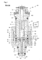
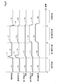
- FIG. 1 is an explanatory diagram showing a schematic configuration of the fuel injection device according to the first embodiment.
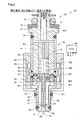
- FIG. 2 is a first explanatory view showing a valve opening operation of the fuel injection device in the first embodiment
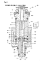
- FIG. 3 is a second explanatory view showing the valve opening operation of the fuel injection device in the first embodiment
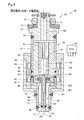
- FIG. 4 is an explanatory view showing a valve closing operation of the fuel injection device in the first embodiment.
- FIG. 5 is a time chart showing an example of a waveform of a drive current in the fuel injection device
- FIG. 6 is an explanatory diagram showing a schematic configuration of the fuel injection device according to the second embodiment.
- FIG. 7 is an explanatory view showing a valve opening operation of the fuel injection device in the second embodiment.
- FIG. 8 is an explanatory diagram showing a schematic configuration of the fuel injection device according to the third embodiment.
- FIG. 9 is an explanatory diagram showing a schematic configuration of a fuel injection device according to another embodiment.
- the fuel injection device 90 of the first embodiment includes an injector 20 and a control unit 80.
- the fuel injection device 90 of the present embodiment injects hydrogen gas that is gaseous fuel by the injector 20.
- the injection of hydrogen gas from the injector 20 is controlled by the control unit 80.
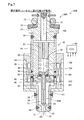
- the injector 20 includes a housing 30, a fixed core 41, a first movable core 42, a second movable core 43, a coil 44, a needle 50, a first spring 61, and a second spring 62. .
- the housing 30 is a cylindrical member in which a nozzle hole 32 for injecting fuel and a first flow path 101 communicating with the nozzle hole 32 are formed.
- the housing 30 of the present embodiment includes, in order from the nozzle hole 32 side, the nozzle tip part 31 in which the nozzle holes 32 are formed, the first magnetic part 34, the nonmagnetic part 36, the second magnetic part 35, and the inlet part. 37.
- a valve seat 33 is provided around the nozzle hole 32 on the inner surface of the housing 30 of the nozzle tip portion 31. Between the nozzle tip part 31 and the first magnetic part 34, between the first magnetic part 34 and the nonmagnetic part 36, between the nonmagnetic part 36 and the second magnetic part 35, and between the second magnetic part 35 and the inlet part.
- the nozzle tip portion 31 is made of martensitic stainless steel that is a nonmagnetic material.
- the first magnetic part 34 and the second magnetic part 35 are made of ferritic stainless steel, which is a magnetic material.
- the nonmagnetic portion 36 is formed of austenitic stainless steel that is a nonmagnetic material.
- a supply pipe (not shown) for supplying fuel to the injector 20 is connected to the inlet portion 37.
- the supply pipe is connected so as to contact a backup ring 72 provided at the inlet portion 37.
- a gap between the supply pipe and the inlet portion 37 is sealed by an O-ring 73 provided on the backup ring 72.
- An inlet channel 103 is formed in the inlet portion 37.
- a filter 71 is provided in the inlet channel 103. The filter 71 collects foreign matter contained in the fuel supplied from the supply pipe and suppresses the foreign matter from flowing into the housing 30.
- the fixed core 41 is a cylindrical member fixed in the housing 30.
- a second flow path 102 communicating with the first flow path 101 is formed in the fixed core 41.
- the opposite side of the second channel 102 from the first channel 101 communicates with the inlet channel 103.
- the fixed core 41 is made of a ferritic stainless steel that is a magnetic material.
- the first movable core 42 is a cylindrical member provided so as to be capable of reciprocating along the axial direction AX of the housing 30 in the first flow path 101 closer to the injection hole 32 than the fixed core 41.
- the first movable core 42 has an outer diameter that is larger than the inner diameter of the fixed core 41.
- the first movable core 42 has a first through hole 421 that is smaller than the inner diameter of the fixed core 41.
- the surface of the first movable core 42 on the fixed core 41 side has a first recess 422 around the first through hole 421.
- the first recess 422 is a circular depression formed on the surface of the first movable core 42 on the fixed core 41 side.
- the first movable core 42 and the fixed core 41 are configured to be contactable in the axial direction AX.
- the 1st movable core 42 is formed with the ferritic stainless steel which is a magnetic material.
- the second movable core 43 is a cylindrical member provided so as to be capable of reciprocating along the axial direction AX in the first flow path 101 between the fixed core 41 and the first movable core 42.
- the second movable core 43 has an outer diameter that is larger than the inner diameter of the fixed core 41 and smaller than the diameter of the first recess 422 of the first movable core 42.
- the second movable core 43 has a second through hole 431 that is smaller than the inner diameter of the fixed core 41.
- the second movable core 43 and the fixed core 41 are configured to be contactable in the axial direction AX.
- the second movable core 43 is configured to be accommodated in the first recess 422 of the first movable core 42.
- the 2nd movable core 43 is formed with the ferritic stainless steel which is a magnetic material.
- the coil 44 is wound around the outer periphery of the housing 30.
- the outer periphery of the coil 44 is covered with a yoke 45 formed of ferritic stainless steel, which is a magnetic material.
- the coil 44 generates a magnetic field that moves the first movable core 42 and the second movable core 43 toward the fixed core 41 when energized.
- the drive current for moving the first movable core 42 and the second movable core 43 is supplied to the coil 44 from a power supply source (not shown) such as a battery, for example.
- the drive current supplied from the power supply source to the coil 44 is controlled by, for example, a control unit 80 configured by an engine ECU or the like.
- the needle 50 includes a shaft portion 51, a valve portion 52, a stopper portion 53, and a flange portion 54.
- the shaft portion 51 is provided so as to be capable of reciprocating in the first through hole 421 along the axial direction AX.
- the central axis of the shaft portion 51 is the same as the central axis of the fixed core 41, the central axis of the first movable core 42, and the central axis of the second movable core 43.
- a communication channel 104 through which fuel flows from the second channel 102 toward the first channel 101 is formed inside the shaft portion 51.
- the valve part 52 is formed at the end of the shaft part 51 on the nozzle hole 32 side.
- the valve portion 52 is configured to be able to come into contact with a valve seat 33 provided in the nozzle tip portion 31, and is a valve body that opens and closes the injection hole 32 when the shaft portion 51 reciprocates along the axial direction AX. .
- the fuel that has flowed through the housing 30 in the order of the inlet channel 103, the second channel 102, the communication channel 104, and the first channel 101 is injected from the nozzle hole 32 when the nozzle hole 32 is opened. .
- the stopper portion 53 is a disk-shaped member located on the valve portion 52 side in the shaft portion 51.
- the stopper portion 53 is larger than the diameter of the first through hole 421 of the first movable core 42 and the diameter of the second through hole 431 of the second movable core 43 in the radial direction of the shaft portion 51, and the first movable core. It protrudes smaller than the diameter of the first concave portion 422 of 42. Therefore, the second movable core 43 is configured to be accommodated in the first recess 422 of the first movable core 42.
- the stopper portion 53 is formed of austenitic stainless steel, which is a nonmagnetic material, and is press-fitted into the shaft portion 51.
- the flange portion 54 is a disk-shaped member located on the fixed core 41 side in the shaft portion 51.
- the flange portion 54 protrudes in the radial direction of the shaft portion 51 larger than the diameter of the second through hole 431 of the second movable core 43 and smaller than the inner diameter of the fixed core 41.
- the shaft portion 51, the valve portion 52, and the flange portion 54 are integrally formed.
- the shaft portion 51, the valve portion 52, and the flange portion 54 are made of martensitic stainless steel, which is a nonmagnetic material.
- the second movable core 43 is welded to the flange portion 54 protruding from the shaft portion 51, and further sandwiched between the flange portion 54 and the stopper portion 53 press-fitted into the shaft portion 51, so that the needle 50 is fixed. Therefore, the second movable core 43 can transmit a force from the nozzle hole 32 side to the fixed core 41 side in the axial direction AX with respect to the needle 50.
- the stopper portion 53 and the flange portion 54 may be referred to as a fixing portion.
- the first recess 422 provided in the first movable core 42 is configured to accommodate the second movable core 43 and the stopper portion 53, and the first movable core 42 is axially disposed on the fixed core 41.
- the second movable core 43 forms a space that can move along the axial direction AX together with the needle 50 while being in contact with each other at AX.
- the first spring 61 is disposed in the second flow path 102.
- the first spring 61 urges the flange portion 54 from the fixed core 41 side toward the injection hole 32 side.
- the first spring 61 is a coil spring.
- An adjusting pipe 63 is provided upstream of the first spring 61 in the second flow path 102.
- the force with which the first spring 61 pushes the flange portion 54 is configured to be adjustable by adjusting the position of the end portion of the adjusting pipe 63 on the injection hole 32 side.
- the second spring 62 is disposed in the first flow path 101 and urges the first movable core 42 from the injection hole 32 side toward the fixed core 41 side.
- the second spring 62 of the present embodiment is a coil spring. In the valve closed state, the first movable core 42 is pushed by the second spring 62, and the stopper portion 53 and the first movable core 42 come into contact with each other.
- valve opening operation performed in the fuel injection device 90 of this embodiment will be described with reference to FIGS.
- the valve portion 52 is in contact with the valve seat 33 in the valve closed state.
- the coil 44 is not energized.
- the flange portion 54 is pushed from the fixed core 41 side toward the nozzle hole 32 side by the first spring 61.
- the first movable core 42 is pushed by the second spring 62 from the nozzle hole 32 side toward the fixed core 41 side. Therefore, the first movable core 42 and the second movable core 43 are in contact with each other.
- this state is also referred to as an initial state.
- a first interval d1 is secured between the surface of the first movable core 42 on the fixed core 41 side and the surface of the fixed core 41 on the injection hole 32 side in the axial direction AX.
- a second interval d2 is secured between the surface of the second movable core 43 on the fixed core 41 side and the surface of the first movable core 42 on the injection hole 32 side in the axial direction AX.
- the second interval d2 is longer than the first interval d1.
- the sum of the first interval d1 and the second interval d2 is the total lift amount L2 by which the needle 50 is lifted from the injection hole 32 side to the fixed core 41 side in the valve open state.
- the first movable core 42 together with the second movable core 43 and the needle 50 are sprayed by the magnetic attractive force from the fixed core 41.
- the first movable core 42 collides with the fixed core 41 by moving from the 32 side toward the fixed core 41 side.
- the distance that the first movable core 42 moves while being accelerated by the magnetic attractive force from the fixed core 41 from the initial state until it collides with the fixed core 41 is the same as the first interval d1, and therefore the total lift amount Shorter than L2.
- the speed of the first movable core 42 when colliding with the fixed core 41 is smaller than that in which the first movable core 42 moves the total lift amount L2 by the magnetic attraction force from the fixed core 41, and the first movable core 42 becomes smaller.
- the impact force when the core 42 and the fixed core 41 collide is reduced. Since the needle 50 moves the same distance as the first interval d1 together with the first movable core 42 from the initial state until the first movable core 42 collides with the fixed core 41, the needle 50 is fixed from the injection hole 32 side.
- the intermediate lift amount L1 that is the same as the first interval d1 is lifted toward the 41 side. Therefore, the valve part 52 moves away from the valve seat 33 and fuel injection from the injection hole 32 is started.
- the state in which the needle 50 is moved from the nozzle hole 32 side toward the fixed core 41 side by the intermediate lift amount L1 from the initial state is also referred to as a first valve opening state.
- the first spring 61 is pushed by the flange portion 54 and contracts, so that elastic energy is stored in the first spring 61.
- the second movable core 43 together with the needle 50 moves from the nozzle hole 32 side to the fixed core 41 side by the magnetic attractive force from the fixed core 41. Further, the second movable core 43 collides with the fixed core 41. Since the second movable core 43 and the needle 50 are configured to be movable independently of the first movable core 42 from the first valve opening state to the collision with the fixed core 41, The impact force when the fixed core 41 collides is reduced.
- the needle 50 moves the same distance as the second interval d2 together with the second movable core 43 from the first valve opening state until the second movable core 43 collides with the fixed core 41, the needle 50 is moved from the initial state,
- the total lift amount L2 that is the same as the sum of the first interval d1 and the second interval d2 is lifted from the nozzle hole 32 side toward the fixed core 41 side. Therefore, the fuel injected from the injection hole 32 increases as the valve portion 52 further moves away from the valve seat 33.
- the state in which the needle 50 is moved from the injection hole 32 side toward the fixed core 41 side by the total lift amount L2 from the initial state is also referred to as a second valve opening state.
- the distance that the first movable core 42 moves toward the fixed core 41 may be referred to as a first distance, and the first movable core 42 contacts the fixed core 41 in the axial direction AX.
- the distance that the second movable core 43 moves toward the fixed core 41 may be referred to as a second distance.
- the second movable core 43 is stopped while being in contact with the fixed core 41 by the magnetic attractive force from the fixed core 41, and the second valve open state is maintained.
- the valve opening operation in the fuel injection device 90 is completed by the series of operations described above.
- the valve closing operation performed in the fuel injection device 90 of the present embodiment will be described with reference to FIG.
- the magnetic attraction force from the fixed core 41 is unloaded, and the needle 50 biased by the first spring 61 is the first.
- the valve portion 52 and the valve seat 33 collide with the movable core 42 and the second movable core 43 moving from the fixed core 41 side toward the injection hole 32 side. Therefore, the valve is closed and the fuel injection from the nozzle hole 32 is stopped.
- the first movable core 42 is configured to be further movable from the fixed core 41 side toward the injection hole 32 side by inertia.
- FIG. 5 shows an example of the waveform of the drive current supplied from the control unit 80 to the coil 44 on the time chart.
- the drive current I represents the current flowing through the coil 44.
- the magnetic attractive force F represents the magnetic attractive force generated by the fixed core 41 when the drive current I flows through the coil 44.
- the displacement X represents the displacement in the axial direction AX of the first movable core 42 from the initial state.
- the displacement Y represents the displacement in the axial direction AX of the second movable core 43 from the initial state.
- the fuel injection rate R represents the fuel injection amount per unit time in the injector 20.
- the control unit 80 does not supply the driving current I to the coil 44 (driving current I0). Therefore, no magnetic attractive force F is generated from the fixed core 41 (magnetic attractive force F0), and the displacement X of the first movable core 42 and the displacement Y of the second movable core 43 remain in the initial state. (Displacement X0, displacement Y0), fuel is not injected (fuel injection rate R0).
- the control unit 80 first supplies a large driving current I1 to the coil 44.
- the drive current I1 may be referred to as a first current.
- a large magnetic attractive force F1 from the fixed core 41 is generated by the drive current I1.
- the first movable core 42 and the second movable core 43 move together by the magnetic attractive force F1, the first movable core 42 becomes the displacement X1, and the second movable core 43 becomes the displacement Y1.
- the displacement X1 of the first movable core 42 and the displacement Y1 of the second movable core 43 are both the same as the intermediate lift amount L1.
- the needle 50 is lifted by the intermediate lift amount L1, and the fuel injection rate R1 corresponding to the intermediate lift amount L1 is obtained.
- the control unit 80 supplies a drive current I2 smaller than the drive current I1 to the coil 44.
- a magnetic attraction force F2 smaller than the magnetic attraction force F1 is generated by the drive current I2.
- a large magnetic attractive force F1 corresponding to the force of the first spring 61 and the force of the fuel pressure is required.
- the control unit 80 supplies the coil 44 with a driving current I3 that is larger than the driving current I2 and smaller than the driving current I1.
- the drive current I3 may be referred to as a second current.
- the drive current I3 generates a magnetic attractive force F3 that is larger than the magnetic attractive force F2 and smaller than the magnetic attractive force F1. Since the first movable core 42 is in contact with the fixed core 41 in the axial direction AX, the displacement of the first movable core 42 remains the displacement X1. On the other hand, the second movable core 43 further moves independently of the first movable core 42, and the displacement of the second movable core 43 becomes a displacement Y2 larger than the displacement Y1.
- the second movable core 43 collides with the fixed core 41 because the second movable core 43 moves from the injection hole 32 side toward the fixed core 41 side by the magnetic attractive force F3 smaller than the magnetic attractive force F1. Speed is reduced. Therefore, the impact force when the second movable core 43 collides with the fixed core 41 is reduced.
- the displacement Y2 of the second movable core 43 is the same as the total lift amount L2. Therefore, the needle 50 is lifted by the total lift amount L2, and the fuel injection rate R2 corresponding to the total lift amount L2 is obtained.
- the control unit 80 supplies the drive current I4 in the direction opposite to the drive current I3 to the coil 44, and then stops the supply of the drive current.
- the magnetic attractive force F from the fixed core 41 is unloaded with good response.
- the needle 50 is pushed back to the first spring 61.
- the displacement X of the first movable core 42 and the displacement Y of the second movable core 43 return to the initial state, and the fuel injection is stopped.
- the distance that the first movable core 42 moves from the initial state until it collides with the fixed core 41 is such that the second movable core 43 is fixed from the initial state. It is shorter than the distance traveled before colliding with the core 41. Therefore, by suppressing the acceleration of the first movable core 42, the speed of the first movable core 42 when colliding with the fixed core 41 is reduced, and when the first movable core 42 and the fixed core 41 collide with each other. The impact force is reduced. Further, since the needle 50 and the second movable core 43 move independently from the first movable core 42 from the first valve opening state until the collision with the fixed core 41, the second movable core 43 and the fixed core 41 are moved. The impact force when the two collide with each other is reduced. Therefore, wear at the contact portion between the first movable core 42 and the fixed core 41 and at the contact portion between the second movable core 43 and the fixed core 41 can be suppressed.
- the contact portion between the first movable core 42 and the fixed core 41 as compared with the form of injecting liquid fuel, the second Since the squeeze force by the fuel when the contact portion between the movable core 43 and the fixed core 41 and the contact portion between the stopper portion 53 and the first movable core 42 collide is small, the impact force at each contact portion increases. Therefore, the effect of suppressing wear of each contact portion is great.
- the magnetic attraction force from the fixed core 41 is reduced by reducing the drive current supplied to the coil 44 by the control unit 80. Therefore, the speed when the second movable core 43 collides with the fixed core 41 is reduced, and the impact force when the second movable core 43 and the fixed core 41 collide can be further reduced.
- the fuel injection rate can be adjusted in multiple stages by adjusting the drive current supplied to the coil 44 by the control unit 80 according to the required combustion injection rate.
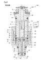
- Second embodiment As shown in FIG. 6, in the fuel injection device 90B of the second embodiment, the configuration of the injector 20B is different from that of the first embodiment. Specifically, the second movable core 43 and the needle 50B are not fixed, and the second movable core 43 contacts the flange portion 54 in the axial direction AX, so that the needle 50B is in the axial direction AX. It is configured to be able to transmit a force from the nozzle hole 32 side toward the fixed core 41 side. Therefore, the shaft portion 51 of the needle 50B can reciprocate in the second through hole 431 along the axial direction AX. Moreover, the stopper part 53 is not provided in the needle 50B.
- the surface of the second movable core 43 on the nozzle hole 32 side is subjected to DLC coating, so that the second movable core 43 that has received the magnetic attractive force from the fixed core 41 is easily separated from the first movable core 42. Yes.
- Other configurations are the same as those of the first embodiment.
- the flange part 54 may be called a protrusion part.
- the valve opening operation in the fuel injection device 90B of the second embodiment will be described.
- the valve opening operation until the second movable core 43 collides with the fixed core 41 is the same as in the first embodiment.
- the needle 50 further moves from the injection hole 32 side toward the fixed core 41 side due to inertia and is pushed back by the first spring 61.
- the second movable core 43 collides again.
- the needle 50 is supported by the second movable core 43, whereby the total lift amount L2 is ensured.
- the impact force when the first movable core 42 collides with the fixed core 41 is reduced by the second movable core 43 and the needle 50 being detached from the first movable core 42.
- the impact force when the second movable core 43 collides with the fixed core 41 is reduced by the needle 50 being detached from the second movable core 43. Therefore, wear at the contact portion between the first movable core 42 and the fixed core 41, the contact portion between the second movable core 43 and the fixed core 41, and the contact portion between the needle 50 and the second movable core 43 can be suppressed.
- the second movable core 43 collides with the fixed core 41 by reducing the drive current supplied to the coil 44 by the control unit 80.
- Speed is reduced.
- the elastic energy stored in the first spring 61 is reduced. Therefore, it is possible to further reduce the impact force when the second movable core 43 and the fixed core 41 collide and the impact force when the needle 50 and the second movable core 43 collide.
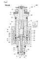
- the liquid fuel is injected by the injector 20C, which is different from the first embodiment.
- the liquid fuel include gasoline and light oil.
- the nozzle tip portion 31C is different from the first embodiment in that a plurality of injection holes 32 are provided. Other configurations and opening / closing operations are the same as those in the first embodiment.
- the injector 20C since the injector 20C is configured to inject liquid fuel, the contact portion between the first movable core 42 and the fixed core 41 compared to the configuration in which the injector 20C injects gaseous fuel.
- the squeeze force due to the fuel when the contact portion between the second movable core 43 and the fixed core 41 and the contact portion between the stopper portion 53 and the first movable core 42 collide is increased, and the impact force at each contact portion is increased. Get smaller.
- the control unit 80 causes the first current (drive current I1) after the first movable core 42 collides with the fixed core 41 to the coil 44.
- a smaller second current (drive current I3) is supplied.
- the control unit 80 may supply the first current (drive current I1) to the coil 44 even after the first movable core 42 collides with the fixed core 41.
- the second movable core 43 is sandwiched between the flange portion 54 and the stopper portion 53.
- the needle 50 is fixed.
- the second movable core 43 may be fixed to the needle 50 by being welded to the shaft portion 51 or the like instead of being fixed by being sandwiched between the flange portion 54 and the stopper portion 53.
- the first movable core 42 is axially directed to the fixed core 41 rather than the first distance in which the first movable core 42 moves toward the fixed core 41 side.
- the second distance by which the second movable core 43 moves toward the fixed core 41 side from the state of contact in AX is longer.
- the first distance may be equal to or less than the second distance.
- the present disclosure is not limited to the above-described embodiment, and can be realized with various configurations without departing from the spirit of the present disclosure.
- the technical features in the embodiments are appropriately replaced or combined to solve part or all of the above-described problems or to achieve part or all of the above-described effects. Is possible.
- the technical feature is not described as essential in the present specification, it can be deleted as appropriate.
Landscapes
- Engineering & Computer Science (AREA)
- Chemical & Material Sciences (AREA)
- Combustion & Propulsion (AREA)
- Mechanical Engineering (AREA)
- General Engineering & Computer Science (AREA)
- Fuel-Injection Apparatus (AREA)
Applications Claiming Priority (2)
| Application Number | Priority Date | Filing Date | Title |
|---|---|---|---|
| JP2018089811A JP6753432B2 (ja) | 2018-05-08 | 2018-05-08 | 燃料噴射装置 |
| JP2018-089811 | 2018-05-08 |
Publications (1)
| Publication Number | Publication Date |
|---|---|
| WO2019216202A1 true WO2019216202A1 (ja) | 2019-11-14 |
Family
ID=68468254
Family Applications (1)
| Application Number | Title | Priority Date | Filing Date |
|---|---|---|---|
| PCT/JP2019/017232 Ceased WO2019216202A1 (ja) | 2018-05-08 | 2019-04-23 | 燃料噴射装置 |
Country Status (2)
| Country | Link |
|---|---|
| JP (1) | JP6753432B2 (enExample) |
| WO (1) | WO2019216202A1 (enExample) |
Families Citing this family (6)
| Publication number | Priority date | Publication date | Assignee | Title |
|---|---|---|---|---|
| JP7376337B2 (ja) * | 2019-12-19 | 2023-11-08 | 株式会社Soken | 燃料噴射弁 |
| DE102020201973A1 (de) * | 2020-01-31 | 2021-08-05 | Robert Bosch Gesellschaft mit beschränkter Haftung | Gasdosierventil für Brennkraftmaschinen |
| KR20220061725A (ko) * | 2020-11-06 | 2022-05-13 | 엘에스일렉트릭(주) | 코일부 및 이를 포함하는 ev 릴레이 |
| DK181102B1 (en) * | 2021-06-24 | 2022-12-15 | Man Energy Solutions Filial Af Man Energy Solutions Se Tyskland | Fuel valve assembly |
| JP2025079606A (ja) * | 2023-11-10 | 2025-05-22 | 株式会社デンソー | ガス燃料噴射弁 |
| JP2025079607A (ja) * | 2023-11-10 | 2025-05-22 | 株式会社デンソー | ガス燃料噴射弁及び燃料噴射システム |
Citations (3)
| Publication number | Priority date | Publication date | Assignee | Title |
|---|---|---|---|---|
| JP2003511604A (ja) * | 1999-10-07 | 2003-03-25 | ローベルト ボツシユ ゲゼルシヤフト ミツト ベシユレンクテル ハフツング | 燃料噴射弁 |
| JP2013167194A (ja) * | 2012-02-15 | 2013-08-29 | Toyota Motor Corp | 燃料噴射弁 |
| WO2018037748A1 (ja) * | 2016-08-26 | 2018-03-01 | 日立オートモティブシステムズ株式会社 | 燃料噴射弁 |
-
2018
- 2018-05-08 JP JP2018089811A patent/JP6753432B2/ja active Active
-
2019
- 2019-04-23 WO PCT/JP2019/017232 patent/WO2019216202A1/ja not_active Ceased
Patent Citations (3)
| Publication number | Priority date | Publication date | Assignee | Title |
|---|---|---|---|---|
| JP2003511604A (ja) * | 1999-10-07 | 2003-03-25 | ローベルト ボツシユ ゲゼルシヤフト ミツト ベシユレンクテル ハフツング | 燃料噴射弁 |
| JP2013167194A (ja) * | 2012-02-15 | 2013-08-29 | Toyota Motor Corp | 燃料噴射弁 |
| WO2018037748A1 (ja) * | 2016-08-26 | 2018-03-01 | 日立オートモティブシステムズ株式会社 | 燃料噴射弁 |
Also Published As
| Publication number | Publication date |
|---|---|
| JP2019196716A (ja) | 2019-11-14 |
| JP6753432B2 (ja) | 2020-09-09 |
Similar Documents
| Publication | Publication Date | Title |
|---|---|---|
| WO2019216202A1 (ja) | 燃料噴射装置 | |
| US7252245B2 (en) | Fuel injection valve | |
| JP6087210B2 (ja) | 燃料噴射弁 | |
| CN102828873B (zh) | 喷射阀的阀组件和喷射阀 | |
| JP6571410B2 (ja) | 電磁弁 | |
| JP2007218204A (ja) | 電磁式燃料噴射弁 | |
| JP6345557B2 (ja) | 燃料噴射装置 | |
| JP6655723B2 (ja) | 燃料噴射弁 | |
| CN107923548B (zh) | 电磁阀 | |
| JP6557608B2 (ja) | 燃料噴射装置の制御装置 | |
| JP6613973B2 (ja) | 燃料噴射装置 | |
| JP2002139168A (ja) | 電磁弁装置およびそれを用いた燃料噴射装置 | |
| US11629678B2 (en) | Fuel injection valve and method for assembling same | |
| WO2015136862A1 (ja) | 燃料噴射装置 | |
| WO2019216207A1 (ja) | インジェクタ | |
| US9394869B2 (en) | Fuel injector | |
| JP4239942B2 (ja) | 燃料噴射弁 | |
| JP6338662B2 (ja) | 燃料噴射弁 | |
| JP4285701B2 (ja) | 燃料噴射弁 | |
| JP2009236095A (ja) | 燃料噴射装置 | |
| US11242830B2 (en) | Fuel injection valve | |
| JP2004232462A (ja) | 電磁式燃料噴射弁 | |
| JP2006170042A (ja) | 燃料噴射弁 | |
| JP2010014124A (ja) | 電磁式燃料噴射弁のハウジング組立体 |
Legal Events
| Date | Code | Title | Description |
|---|---|---|---|
| 121 | Ep: the epo has been informed by wipo that ep was designated in this application |
Ref document number: 19798829 Country of ref document: EP Kind code of ref document: A1 |
|
| NENP | Non-entry into the national phase |
Ref country code: DE |
|
| 122 | Ep: pct application non-entry in european phase |
Ref document number: 19798829 Country of ref document: EP Kind code of ref document: A1 |