WO2019216193A1 - 電磁流量制御弁 - Google Patents
電磁流量制御弁 Download PDFInfo
- Publication number
- WO2019216193A1 WO2019216193A1 PCT/JP2019/017158 JP2019017158W WO2019216193A1 WO 2019216193 A1 WO2019216193 A1 WO 2019216193A1 JP 2019017158 W JP2019017158 W JP 2019017158W WO 2019216193 A1 WO2019216193 A1 WO 2019216193A1
- Authority
- WO
- WIPO (PCT)
- Prior art keywords
- pilot
- spool
- pilot pressure
- pressure chamber
- outlet
- Prior art date
- Legal status (The legal status is an assumption and is not a legal conclusion. Google has not performed a legal analysis and makes no representation as to the accuracy of the status listed.)
- Ceased
Links
Images


Classifications
-
- F—MECHANICAL ENGINEERING; LIGHTING; HEATING; WEAPONS; BLASTING
- F16—ENGINEERING ELEMENTS AND UNITS; GENERAL MEASURES FOR PRODUCING AND MAINTAINING EFFECTIVE FUNCTIONING OF MACHINES OR INSTALLATIONS; THERMAL INSULATION IN GENERAL
- F16K—VALVES; TAPS; COCKS; ACTUATING-FLOATS; DEVICES FOR VENTING OR AERATING
- F16K31/00—Actuating devices; Operating means; Releasing devices
- F16K31/02—Actuating devices; Operating means; Releasing devices electric; magnetic
- F16K31/06—Actuating devices; Operating means; Releasing devices electric; magnetic using a magnet, e.g. diaphragm valves, cutting off by means of a liquid
- F16K31/0644—One-way valve
- F16K31/0655—Lift valves
-
- F—MECHANICAL ENGINEERING; LIGHTING; HEATING; WEAPONS; BLASTING
- F15—FLUID-PRESSURE ACTUATORS; HYDRAULICS OR PNEUMATICS IN GENERAL
- F15B—SYSTEMS ACTING BY MEANS OF FLUIDS IN GENERAL; FLUID-PRESSURE ACTUATORS, e.g. SERVOMOTORS; DETAILS OF FLUID-PRESSURE SYSTEMS, NOT OTHERWISE PROVIDED FOR
- F15B11/00—Servomotor systems without provision for follow-up action; Circuits therefor
- F15B11/02—Systems essentially incorporating special features for controlling the speed or actuating force of an output member
- F15B11/04—Systems essentially incorporating special features for controlling the speed or actuating force of an output member for controlling the speed
- F15B11/044—Systems essentially incorporating special features for controlling the speed or actuating force of an output member for controlling the speed by means in the return line, i.e. "meter out"
-
- F—MECHANICAL ENGINEERING; LIGHTING; HEATING; WEAPONS; BLASTING
- F15—FLUID-PRESSURE ACTUATORS; HYDRAULICS OR PNEUMATICS IN GENERAL
- F15B—SYSTEMS ACTING BY MEANS OF FLUIDS IN GENERAL; FLUID-PRESSURE ACTUATORS, e.g. SERVOMOTORS; DETAILS OF FLUID-PRESSURE SYSTEMS, NOT OTHERWISE PROVIDED FOR
- F15B13/00—Details of servomotor systems ; Valves for servomotor systems
- F15B13/02—Fluid distribution or supply devices characterised by their adaptation to the control of servomotors
- F15B13/04—Fluid distribution or supply devices characterised by their adaptation to the control of servomotors for use with a single servomotor
- F15B13/0401—Valve members; Fluid interconnections therefor
- F15B13/0402—Valve members; Fluid interconnections therefor for linearly sliding valves, e.g. spool valves
-
- F—MECHANICAL ENGINEERING; LIGHTING; HEATING; WEAPONS; BLASTING
- F15—FLUID-PRESSURE ACTUATORS; HYDRAULICS OR PNEUMATICS IN GENERAL
- F15B—SYSTEMS ACTING BY MEANS OF FLUIDS IN GENERAL; FLUID-PRESSURE ACTUATORS, e.g. SERVOMOTORS; DETAILS OF FLUID-PRESSURE SYSTEMS, NOT OTHERWISE PROVIDED FOR
- F15B13/00—Details of servomotor systems ; Valves for servomotor systems
- F15B13/02—Fluid distribution or supply devices characterised by their adaptation to the control of servomotors
- F15B13/04—Fluid distribution or supply devices characterised by their adaptation to the control of servomotors for use with a single servomotor
- F15B13/042—Fluid distribution or supply devices characterised by their adaptation to the control of servomotors for use with a single servomotor operated by fluid pressure
- F15B13/043—Fluid distribution or supply devices characterised by their adaptation to the control of servomotors for use with a single servomotor operated by fluid pressure with electrically-controlled pilot valves
- F15B13/0435—Fluid distribution or supply devices characterised by their adaptation to the control of servomotors for use with a single servomotor operated by fluid pressure with electrically-controlled pilot valves the pilot valves being sliding valves
-
- F—MECHANICAL ENGINEERING; LIGHTING; HEATING; WEAPONS; BLASTING
- F16—ENGINEERING ELEMENTS AND UNITS; GENERAL MEASURES FOR PRODUCING AND MAINTAINING EFFECTIVE FUNCTIONING OF MACHINES OR INSTALLATIONS; THERMAL INSULATION IN GENERAL
- F16K—VALVES; TAPS; COCKS; ACTUATING-FLOATS; DEVICES FOR VENTING OR AERATING
- F16K31/00—Actuating devices; Operating means; Releasing devices
- F16K31/12—Actuating devices; Operating means; Releasing devices actuated by fluid
- F16K31/122—Actuating devices; Operating means; Releasing devices actuated by fluid the fluid acting on a piston
- F16K31/1221—Actuating devices; Operating means; Releasing devices actuated by fluid the fluid acting on a piston one side of the piston being spring-loaded
-
- F—MECHANICAL ENGINEERING; LIGHTING; HEATING; WEAPONS; BLASTING
- F16—ENGINEERING ELEMENTS AND UNITS; GENERAL MEASURES FOR PRODUCING AND MAINTAINING EFFECTIVE FUNCTIONING OF MACHINES OR INSTALLATIONS; THERMAL INSULATION IN GENERAL
- F16K—VALVES; TAPS; COCKS; ACTUATING-FLOATS; DEVICES FOR VENTING OR AERATING
- F16K31/00—Actuating devices; Operating means; Releasing devices
- F16K31/12—Actuating devices; Operating means; Releasing devices actuated by fluid
- F16K31/42—Actuating devices; Operating means; Releasing devices actuated by fluid by means of electrically-actuated members in the supply or discharge conduits of the fluid motor
-
- F—MECHANICAL ENGINEERING; LIGHTING; HEATING; WEAPONS; BLASTING
- F15—FLUID-PRESSURE ACTUATORS; HYDRAULICS OR PNEUMATICS IN GENERAL
- F15B—SYSTEMS ACTING BY MEANS OF FLUIDS IN GENERAL; FLUID-PRESSURE ACTUATORS, e.g. SERVOMOTORS; DETAILS OF FLUID-PRESSURE SYSTEMS, NOT OTHERWISE PROVIDED FOR
- F15B2211/00—Circuits for servomotor systems
- F15B2211/30—Directional control
- F15B2211/305—Directional control characterised by the type of valves
- F15B2211/30505—Non-return valves, i.e. check valves
- F15B2211/30515—Load holding valves
-
- F—MECHANICAL ENGINEERING; LIGHTING; HEATING; WEAPONS; BLASTING
- F15—FLUID-PRESSURE ACTUATORS; HYDRAULICS OR PNEUMATICS IN GENERAL
- F15B—SYSTEMS ACTING BY MEANS OF FLUIDS IN GENERAL; FLUID-PRESSURE ACTUATORS, e.g. SERVOMOTORS; DETAILS OF FLUID-PRESSURE SYSTEMS, NOT OTHERWISE PROVIDED FOR
- F15B2211/00—Circuits for servomotor systems
- F15B2211/30—Directional control
- F15B2211/31—Directional control characterised by the positions of the valve element
- F15B2211/3144—Directional control characterised by the positions of the valve element the positions being continuously variable, e.g. as realised by proportional valves
-
- F—MECHANICAL ENGINEERING; LIGHTING; HEATING; WEAPONS; BLASTING
- F15—FLUID-PRESSURE ACTUATORS; HYDRAULICS OR PNEUMATICS IN GENERAL
- F15B—SYSTEMS ACTING BY MEANS OF FLUIDS IN GENERAL; FLUID-PRESSURE ACTUATORS, e.g. SERVOMOTORS; DETAILS OF FLUID-PRESSURE SYSTEMS, NOT OTHERWISE PROVIDED FOR
- F15B2211/00—Circuits for servomotor systems
- F15B2211/30—Directional control
- F15B2211/32—Directional control characterised by the type of actuation
- F15B2211/327—Directional control characterised by the type of actuation electrically or electronically
-
- F—MECHANICAL ENGINEERING; LIGHTING; HEATING; WEAPONS; BLASTING
- F15—FLUID-PRESSURE ACTUATORS; HYDRAULICS OR PNEUMATICS IN GENERAL
- F15B—SYSTEMS ACTING BY MEANS OF FLUIDS IN GENERAL; FLUID-PRESSURE ACTUATORS, e.g. SERVOMOTORS; DETAILS OF FLUID-PRESSURE SYSTEMS, NOT OTHERWISE PROVIDED FOR
- F15B2211/00—Circuits for servomotor systems
- F15B2211/30—Directional control
- F15B2211/32—Directional control characterised by the type of actuation
- F15B2211/329—Directional control characterised by the type of actuation actuated by fluid pressure
-
- F—MECHANICAL ENGINEERING; LIGHTING; HEATING; WEAPONS; BLASTING
- F15—FLUID-PRESSURE ACTUATORS; HYDRAULICS OR PNEUMATICS IN GENERAL
- F15B—SYSTEMS ACTING BY MEANS OF FLUIDS IN GENERAL; FLUID-PRESSURE ACTUATORS, e.g. SERVOMOTORS; DETAILS OF FLUID-PRESSURE SYSTEMS, NOT OTHERWISE PROVIDED FOR
- F15B2211/00—Circuits for servomotor systems
- F15B2211/30—Directional control
- F15B2211/35—Directional control combined with flow control
- F15B2211/353—Flow control by regulating means in return line, i.e. meter-out control
-
- F—MECHANICAL ENGINEERING; LIGHTING; HEATING; WEAPONS; BLASTING
- F15—FLUID-PRESSURE ACTUATORS; HYDRAULICS OR PNEUMATICS IN GENERAL
- F15B—SYSTEMS ACTING BY MEANS OF FLUIDS IN GENERAL; FLUID-PRESSURE ACTUATORS, e.g. SERVOMOTORS; DETAILS OF FLUID-PRESSURE SYSTEMS, NOT OTHERWISE PROVIDED FOR
- F15B2211/00—Circuits for servomotor systems
- F15B2211/30—Directional control
- F15B2211/355—Pilot pressure control
-
- F—MECHANICAL ENGINEERING; LIGHTING; HEATING; WEAPONS; BLASTING
- F15—FLUID-PRESSURE ACTUATORS; HYDRAULICS OR PNEUMATICS IN GENERAL
- F15B—SYSTEMS ACTING BY MEANS OF FLUIDS IN GENERAL; FLUID-PRESSURE ACTUATORS, e.g. SERVOMOTORS; DETAILS OF FLUID-PRESSURE SYSTEMS, NOT OTHERWISE PROVIDED FOR
- F15B2211/00—Circuits for servomotor systems
- F15B2211/40—Flow control
- F15B2211/405—Flow control characterised by the type of flow control means or valve
- F15B2211/40507—Flow control characterised by the type of flow control means or valve with constant throttles or orifices
-
- F—MECHANICAL ENGINEERING; LIGHTING; HEATING; WEAPONS; BLASTING
- F15—FLUID-PRESSURE ACTUATORS; HYDRAULICS OR PNEUMATICS IN GENERAL
- F15B—SYSTEMS ACTING BY MEANS OF FLUIDS IN GENERAL; FLUID-PRESSURE ACTUATORS, e.g. SERVOMOTORS; DETAILS OF FLUID-PRESSURE SYSTEMS, NOT OTHERWISE PROVIDED FOR
- F15B2211/00—Circuits for servomotor systems
- F15B2211/40—Flow control
- F15B2211/41—Flow control characterised by the positions of the valve element
- F15B2211/413—Flow control characterised by the positions of the valve element the positions being continuously variable, e.g. as realised by proportional valves
-
- F—MECHANICAL ENGINEERING; LIGHTING; HEATING; WEAPONS; BLASTING
- F15—FLUID-PRESSURE ACTUATORS; HYDRAULICS OR PNEUMATICS IN GENERAL
- F15B—SYSTEMS ACTING BY MEANS OF FLUIDS IN GENERAL; FLUID-PRESSURE ACTUATORS, e.g. SERVOMOTORS; DETAILS OF FLUID-PRESSURE SYSTEMS, NOT OTHERWISE PROVIDED FOR
- F15B2211/00—Circuits for servomotor systems
- F15B2211/40—Flow control
- F15B2211/415—Flow control characterised by the connections of the flow control means in the circuit
- F15B2211/41581—Flow control characterised by the connections of the flow control means in the circuit being connected to an output member and a return line
-
- F—MECHANICAL ENGINEERING; LIGHTING; HEATING; WEAPONS; BLASTING
- F15—FLUID-PRESSURE ACTUATORS; HYDRAULICS OR PNEUMATICS IN GENERAL
- F15B—SYSTEMS ACTING BY MEANS OF FLUIDS IN GENERAL; FLUID-PRESSURE ACTUATORS, e.g. SERVOMOTORS; DETAILS OF FLUID-PRESSURE SYSTEMS, NOT OTHERWISE PROVIDED FOR
- F15B2211/00—Circuits for servomotor systems
- F15B2211/40—Flow control
- F15B2211/42—Flow control characterised by the type of actuation
- F15B2211/426—Flow control characterised by the type of actuation electrically or electronically
-
- F—MECHANICAL ENGINEERING; LIGHTING; HEATING; WEAPONS; BLASTING
- F15—FLUID-PRESSURE ACTUATORS; HYDRAULICS OR PNEUMATICS IN GENERAL
- F15B—SYSTEMS ACTING BY MEANS OF FLUIDS IN GENERAL; FLUID-PRESSURE ACTUATORS, e.g. SERVOMOTORS; DETAILS OF FLUID-PRESSURE SYSTEMS, NOT OTHERWISE PROVIDED FOR
- F15B2211/00—Circuits for servomotor systems
- F15B2211/40—Flow control
- F15B2211/42—Flow control characterised by the type of actuation
- F15B2211/428—Flow control characterised by the type of actuation actuated by fluid pressure
-
- F—MECHANICAL ENGINEERING; LIGHTING; HEATING; WEAPONS; BLASTING
- F15—FLUID-PRESSURE ACTUATORS; HYDRAULICS OR PNEUMATICS IN GENERAL
- F15B—SYSTEMS ACTING BY MEANS OF FLUIDS IN GENERAL; FLUID-PRESSURE ACTUATORS, e.g. SERVOMOTORS; DETAILS OF FLUID-PRESSURE SYSTEMS, NOT OTHERWISE PROVIDED FOR
- F15B2211/00—Circuits for servomotor systems
- F15B2211/40—Flow control
- F15B2211/46—Control of flow in the return line, i.e. meter-out control
-
- F—MECHANICAL ENGINEERING; LIGHTING; HEATING; WEAPONS; BLASTING
- F15—FLUID-PRESSURE ACTUATORS; HYDRAULICS OR PNEUMATICS IN GENERAL
- F15B—SYSTEMS ACTING BY MEANS OF FLUIDS IN GENERAL; FLUID-PRESSURE ACTUATORS, e.g. SERVOMOTORS; DETAILS OF FLUID-PRESSURE SYSTEMS, NOT OTHERWISE PROVIDED FOR
- F15B2211/00—Circuits for servomotor systems
- F15B2211/60—Circuit components or control therefor
- F15B2211/635—Circuits providing pilot pressure to pilot pressure-controlled fluid circuit elements
- F15B2211/6355—Circuits providing pilot pressure to pilot pressure-controlled fluid circuit elements having valve means
-
- F—MECHANICAL ENGINEERING; LIGHTING; HEATING; WEAPONS; BLASTING
- F15—FLUID-PRESSURE ACTUATORS; HYDRAULICS OR PNEUMATICS IN GENERAL
- F15B—SYSTEMS ACTING BY MEANS OF FLUIDS IN GENERAL; FLUID-PRESSURE ACTUATORS, e.g. SERVOMOTORS; DETAILS OF FLUID-PRESSURE SYSTEMS, NOT OTHERWISE PROVIDED FOR
- F15B2211/00—Circuits for servomotor systems
- F15B2211/70—Output members, e.g. hydraulic motors or cylinders or control therefor
- F15B2211/76—Control of force or torque of the output member
- F15B2211/761—Control of a negative load, i.e. of a load generating hydraulic energy
-
- F—MECHANICAL ENGINEERING; LIGHTING; HEATING; WEAPONS; BLASTING
- F15—FLUID-PRESSURE ACTUATORS; HYDRAULICS OR PNEUMATICS IN GENERAL
- F15B—SYSTEMS ACTING BY MEANS OF FLUIDS IN GENERAL; FLUID-PRESSURE ACTUATORS, e.g. SERVOMOTORS; DETAILS OF FLUID-PRESSURE SYSTEMS, NOT OTHERWISE PROVIDED FOR
- F15B2211/00—Circuits for servomotor systems
- F15B2211/80—Other types of control related to particular problems or conditions
- F15B2211/85—Control during special operating conditions
- F15B2211/853—Control during special operating conditions during stopping
-
- F—MECHANICAL ENGINEERING; LIGHTING; HEATING; WEAPONS; BLASTING
- F15—FLUID-PRESSURE ACTUATORS; HYDRAULICS OR PNEUMATICS IN GENERAL
- F15B—SYSTEMS ACTING BY MEANS OF FLUIDS IN GENERAL; FLUID-PRESSURE ACTUATORS, e.g. SERVOMOTORS; DETAILS OF FLUID-PRESSURE SYSTEMS, NOT OTHERWISE PROVIDED FOR
- F15B2211/00—Circuits for servomotor systems
- F15B2211/80—Other types of control related to particular problems or conditions
- F15B2211/86—Control during or prevention of abnormal conditions
- F15B2211/863—Control during or prevention of abnormal conditions the abnormal condition being a hydraulic or pneumatic failure
- F15B2211/8633—Pressure source supply failure
-
- Y—GENERAL TAGGING OF NEW TECHNOLOGICAL DEVELOPMENTS; GENERAL TAGGING OF CROSS-SECTIONAL TECHNOLOGIES SPANNING OVER SEVERAL SECTIONS OF THE IPC; TECHNICAL SUBJECTS COVERED BY FORMER USPC CROSS-REFERENCE ART COLLECTIONS [XRACs] AND DIGESTS
- Y10—TECHNICAL SUBJECTS COVERED BY FORMER USPC
- Y10T—TECHNICAL SUBJECTS COVERED BY FORMER US CLASSIFICATION
- Y10T137/00—Fluid handling
- Y10T137/8593—Systems
- Y10T137/87169—Supply and exhaust
- Y10T137/87177—With bypass
- Y10T137/87185—Controlled by supply or exhaust valve
Definitions
- the present invention relates to an electromagnetic flow control valve.
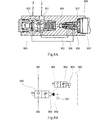
- FIGS. 8A and 8B show an electromagnetic flow control valve 900 according to a conventional example as disclosed in Patent Document 1, for example.
- the control valve 900 controls the flow rate from the inlet port 901 to the outlet port 902 in accordance with the input current value to the proportional solenoid 903.
- the control valve 900 constitutes a meter-out circuit, the inlet port 901 is connected to a hydraulic cylinder, and the outlet port 902 is connected to a tank.
- the control valve 900 includes an inlet passage 905 that connects the inlet port 901 to the pilot pressure chamber 904, an outlet passage 906 that connects the pilot pressure chamber 904 to the outlet port 902, and a fixed throttle 907 interposed on the outlet passage 906. Further, the control valve 900 includes a pilot operation unit 908 and a flow rate control unit 909. The pilot operation unit 908 opens the inlet path 905 with an opening degree corresponding to the input current value.
- the pilot pressure chamber 904 is always connected to the outlet port 902 via the outlet passage 906, but due to the presence of the fixed throttle 907, the pilot pressure corresponding to the input current value is generated in the pilot pressure chamber 904 in the excited state of the proportional solenoid 903. appear.
- the flow rate control unit 909 controls the flow rate from the inlet port 901 to the outlet port 902 according to the pilot pressure in the pilot pressure chamber 904. The flow rate is approximately proportional to the input current value and thus the pilot pressure.
- the pilot operating unit 908 closes the inlet passage 905, and the internal pressure of the pilot pressure chamber 904 becomes the same pressure as that of the outlet port 902.
- the flow rate control unit 909 blocks the inlet port 901 from the outlet port 902 and stops the flow of hydraulic fluid from the inlet port 901 to the outlet port 902.
- the hydraulic fluid in the pilot pressure chamber 904 passes through the fixed restrictor 907 and exits from the outlet port. It is discharged to 902. Since the discharge flow rate is limited by the fixed throttle 907, it is difficult to quickly reduce the internal pressure of the pilot pressure chamber 904 and to quickly stop the flow of hydraulic fluid from the inlet port 901 to the outlet port 902.
- an object of the present invention is to provide an electromagnetic flow control valve capable of quickly stopping the flow of hydraulic fluid from the inlet port to the outlet port when switching from the excited state to the non-excited state.
- An electromagnetic flow control valve includes an inlet port and an outlet port, a housing having a pilot pressure chamber therein, an inlet passage communicating the inlet port with the pilot pressure chamber, and the pilot An outlet path communicating with the outlet port, a fixed throttle provided on the outlet path, a bypass path bypassing the fixed throttle and communicating the pilot pressure chamber with the outlet port, a solenoid, and When the solenoid is not excited, the inlet path is closed, and when the solenoid is excited, the inlet path is opened with an opening corresponding to the input current value to generate a pilot pressure corresponding to the input current value in the pilot pressure chamber.
- a pilot spool that opens the bypass when the input current value is less than a predetermined value, and closes the bypass when the input current value is equal to or greater than the predetermined value; And a main spool for controlling the flow to said outlet port from said inlet port in response to the pilot pressure of the pilot pressure chamber.
- the bypass path is switched from the closed state to the released state by the action of the opening / closing portion.
- the fluid in the pilot pressure chamber passes through not only the outlet passage in which the fixed throttle is interposed but also the bypass passage, and is discharged to the outlet port. Since the discharge flow rate increases by the amount that passes through the bypass passage, the internal pressure of the pilot pressure chamber decreases quickly, and the flow of hydraulic fluid from the inlet port to the outlet port can be stopped quickly.
- the housing has an outlet communication space formed on an outer surface side of the pilot spool and communicated with the outlet port, and the bypass passage is formed in the pilot spool and communicates with the pilot pressure chamber and the pilot.
- the pilot spool includes a radial through hole opened on an outer peripheral surface of the spool, and the pilot spool is blocked from a state where the radial through hole communicates with the outlet communication space and the outlet communication space according to a stroke amount of the pilot spool. The state to be switched may be switched.
- the pilot spool can be provided with a part of the bypass passage and a structure for opening and closing the bypass passage, the electromagnetic flow control valve can be reduced in size.
- the flow rate control unit includes a main spool that is displaced in the axial direction, and a part of the outlet path includes a passage in the spool that is formed inside the main spool and communicates the pilot pressure chamber with the outlet port.
- the fixed throttle may be provided in the middle of the passage in the spool in the main spool.
- the electromagnetic flow control valve can be downsized.
- the load pressure generated in the hydraulic cylinder may act on the inlet port.
- the hydraulic cylinder can be quickly stopped if the load pressure is applied in the hydraulic cylinder.
- an electromagnetic flow rate control valve capable of quickly stopping the flow of hydraulic fluid from the inlet port to the outlet port when switching from the excited state to the non-excited state.
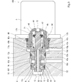
- FIG. 3 is a partially enlarged view of FIG. 2 and shows a pilot operation unit.
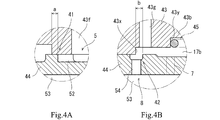
- 4A and 4B are partially enlarged views of FIG. 2 or FIG. 3,
- FIG. 4A shows a variable aperture of the pilot operating unit, and
- FIG. 4B shows an opening / closing unit of the pilot operating unit.
- It is an opening area diagram in a pilot operation part.
- FIG. 8A is a sectional view showing an electromagnetic flow control valve according to a conventional example
- FIG. 8B is a circuit diagram showing an electromagnetic flow control valve according to a conventional example.
- FIG. 1 is a circuit diagram showing an electromagnetic flow control valve (hereinafter simply referred to as “control valve”) 100 according to the first embodiment.
- the control valve 100 includes an inlet port 1, an outlet port 2 and a solenoid 3.
- the control valve 100 controls the flow rate from the inlet port 1 to the outlet port 2 according to the input current value to the solenoid 3 (the current value of the electric signal input to the solenoid 3).
- the solenoid 3 is a proportional solenoid as represented by a circuit symbol.
- the control valve 100 is a hydraulic drive system 90 that drives a working machine attached to an agricultural machine or a construction machine, and is applied as a component of a meter-out circuit.
- the hydraulic drive system 90 includes a control device 91 that outputs an electrical signal to the solenoid 3, a hydraulic cylinder 92 that drives the work machine, and a tank 93 that stores hydraulic oil.
- the inlet port 1 is connected to the head oil chamber 92 a of the hydraulic cylinder 92, and the outlet port 2 is connected to the tank 93.
- the head oil chamber 92a is positioned below the rod oil chamber 92b.
- a load pressure is generated in the head oil chamber 92a in accordance with the load of the hydraulic cylinder 92 such as the weight of the work implement and the external force acting on the work implement.
- the control valve 100 controls the amount of hydraulic oil flowing out from the hydraulic cylinder 92 back to the tank 93, and consequently controls the contraction speed of the hydraulic cylinder 92 and the lowering speed of the work implement. Further, the control valve 100 can stop the flow of hydraulic oil from the hydraulic cylinder 92 to the tank 93, and can maintain an arbitrary amount of stroke of the hydraulic cylinder 92 under a situation where load pressure is generated in the head oil chamber 92a.
- the pressure at the inlet port 1 may be referred to as load pressure
- the pressure at the outlet port 2 may be referred to as tank pressure.
- the control valve 100 includes a pilot pressure chamber 4, an inlet path 5, an outlet path 6, a fixed throttle 7, a bypass path 8, a flow rate control unit 20, and a pilot operation unit 40.
- the flow control unit 20 and the pilot operation unit 40 are structurally realized by a spool valve.
- the flow control unit 20 includes a main spool 24, and the pilot operation unit 40 includes a pilot spool 44 (see FIG. 2).
- the “stroke amount” is the amount of movement from the neutral position of the spool.
- the inlet channel 5 communicates the inlet port 1 with the pilot pressure chamber 4.
- the outlet passage 6 communicates the pilot pressure chamber 4 with the outlet port 2.
- the fixed throttle 7 is interposed on the outlet path 6.
- the pilot pressure chamber 4 is always communicated with the outlet port 2 through the outlet passage 6 with the fixed throttle 7 (regardless of the stroke amount of the pilot spool 44).
- the bypass path 8 bypasses the outlet path 6 and communicates the pilot pressure chamber 4 with the outlet port 2.
- the inlet path 5 and the bypass path 8 are opened and closed at the pilot operation unit 40.
- the pilot operation unit 40 is provided with a variable throttle 41 and an opening / closing unit 42.
- the variable throttle 41 changes the opening degree of the inlet passage 5 in accordance with the input current value and thus the stroke amount of the pilot spool 44.
- the variable throttle 41 closes the inlet path 5 and the input current value is greater than or equal to the first predetermined value. (If the stroke amount is a or more), the pressure in the inlet passage 5 is reduced, and the pilot pressure chamber 4 is controlled to a pressure substantially proportional to the input current value.
- the opening / closing unit 42 closes the bypass 8 and the input current value is less than the second predetermined value.
- the bypass path 8 is opened (if the stroke amount is less than b).
- the first predetermined value is set to a value equal to or greater than the second predetermined value, and the relationship between the first movement amount a and the second movement amount b is the same (a ⁇ b). As a result, it is possible to prevent the bypass 8 from being opened when the variable throttle 41 is open (the pilot pressure is in the controlled state).
- the upstream portion of the bypass passage 8 is shown to partially share the passage with the inlet passage 5 or the outlet passage 6, but this is because the pilot operating portion 40 has a variable throttle 41 and an opening / closing portion 42. This is for the convenience of showing the points provided and the points where the inlet path 5 and the bypass path 8 are not opened simultaneously.
- the bypass path 8 is independent of the inlet path 5.
- the upstream portion of the bypass path 8 may be independent from the outlet path 6 (first and third embodiments), or may partially share the passage with the outlet path 6 (second embodiment). .
- the pilot operation unit 40 is in a neutral state (see the left function).
- the inlet path 5 is closed, and the bypass path 8 is opened by the opening / closing part 42.
- the pilot pressure chamber 4 communicates with the outlet port 2 through both the outlet path 6 and the bypass path 8.
- the internal pressure of the pilot pressure chamber 4 becomes the same as the tank pressure, and the flow rate control unit 20 is in a neutral state (see the left function).
- the flow control unit 20 shuts off the inlet port 1 from the outlet port 2, thereby stopping the flow of hydraulic oil from the inlet port 1 to the outlet port 2.
- the operation of the hydraulic cylinder 92 is stopped and the load of the hydraulic cylinder 92 is maintained.
- the pilot operation unit 40 is in the operating state (see the right function).
- the variable throttle 41 opens the inlet path 5 at an opening degree corresponding to the input current value.
- the hydraulic oil flows from the inlet port 1 to the pilot pressure chamber 4 through the inlet passage 5 with the variable throttle 41.
- the bypass path 8 is closed by the opening / closing part 42, and the hydraulic oil flows from the pilot pressure chamber 4 to the outlet port 2 only through the outlet path 6 with the fixed throttle 7. Due to the presence of the fixed throttle 7, a pilot pressure approximately proportional to the input current value is generated in the pilot pressure chamber 4, whereby the flow rate control unit 20 is activated (see the right function).
- the flow rate control unit 20 controls the flow rate from the inlet port 1 to the outlet port 2 as the main spool 24 strokes according to the pilot pressure.
- the main spool 24 is provided with a variable throttle 21 that changes the opening degree between the inlet port 1 and the outlet port 2 according to the stroke amount.
- the variable throttle 21 is configured to increase the opening as the pilot pressure increases.
- the flow rate from the inlet port 1 to the outlet port 2 is approximately proportional to the input current value, the opening degree of the variable throttle 41, the pilot pressure, or the opening degree of the variable throttle 21.
- the contraction speed of the hydraulic cylinder 92 and thus the down speed of the work implement can be controlled by the control device 91.
- the pilot pressure chamber 4 When the solenoid 3 switches from the excited state to the non-excited state and tries to hold the cylinder 92, the pilot pressure chamber 4 is connected to the outlet port 2 through the bypass path 8 as well as the outlet path 6. In order to hold the cylinder 92, it is necessary to lower the internal pressure of the pilot pressure chamber 4 in order to close the variable throttle 21, and the discharge flow rate is determined by the diameter of the main spool 24 and the stroke amount.
- the discharge path from the pilot pressure chamber 4 to the tank 93 is increased by an amount corresponding to the passage through the bypass path 8 that is opened larger than the fixed throttle 7, and the internal pressure of the pilot pressure chamber 4 is reduced to the tank pressure Can be quickly reduced.
- the flow rate control unit 20 can quickly return from the operating state to the neutral state after the input current value becomes zero, and can quickly stop the flow of hydraulic oil from the inlet port 1 to the outlet port 2.
- the time until the operation of the hydraulic cylinder 92 actually stops after the control device 91 outputs the stop command of the hydraulic cylinder 92 (after the output of the electric signal is stopped). Becomes shorter. That is, the stop responsiveness of the hydraulic cylinder 92 is improved.
- the hydraulic drive system 90 becomes relatively large, it may be necessary to increase the size of the control valve 100 itself applied thereto. In this case, the volume of hydraulic oil to be discharged from the pilot pressure chamber 4 when switching to the non-excited state is increased. According to the present embodiment, a large volume of hydraulic oil can be quickly discharged by improving the discharge flow rate, which is particularly beneficial when applied to a large system.
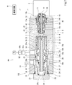
- FIG. 2 is a cross-sectional view of the control valve 100 according to the first embodiment.
- 3 is a cross-sectional view of the pilot operation unit 40
- FIGS. 4A and 4B are partially enlarged views of FIG. 2 or FIG. 3
- FIG. 4A shows a variable throttle 41
- FIG. 4A shows a variable throttle 41
- FIG. 2 is a cross-sectional view of the control valve 100 according to the first embodiment.
- FIG. 4A and 4B are partially enlarged views of FIG. 2 or FIG. 3
- FIG. 4A shows a variable throttle 41
- FIG. In these sectional views the flow control unit 20 and the pilot operation unit 40 are in a neutral state.
- the left-right direction of the cross-sectional view corresponds to the longitudinal direction or axial direction of the housing, the axial direction of the bore, the axial direction or moving direction of the spool and push rod, or the axial direction and extension / contraction direction of the spring.
- the left side corresponds to “one” in the direction
- the control valve 100 includes a housing 10 in which a first bore 11 and a second bore 12 are formed.
- the first bore 11 is formed at one end of the housing 10 and is open to one end surface of the housing 10.
- the second bore 12 is formed at the other end of the housing 10 and is open to the other end surface of the housing 10.
- the first bore 11 and the second bore 12 have a circular cross section and are arranged coaxially.
- a flow control unit 20 is provided in the first bore 11 and a pilot operation unit 40 is provided in the second bore 12.
- a solenoid 3 is attached to the other end surface of the housing 10, and the second bore 12 is closed by the solenoid 3.
- the second bore 12 is formed in a stepped shape in which the inner diameter decreases toward the back side (one side), and the back portion (one end portion) of the second bore 12 functions as the pilot pressure chamber 4.
- the pilot pressure generated in the pilot pressure chamber 4 acts on the flow rate control unit 20 through the through hole 13.
- the housing 10 has an inlet port 1 and an outlet port 2, and the ports 1 and 2 are opened on the outer peripheral surface of the housing 10.
- the housing 10 has an inlet annular groove 14 and an outlet annular groove 15 formed on the inner peripheral surface of the first bore 11.
- an annular inlet communication space 16 and a first outlet communication space 17a are formed between the inner surface of the second bore 12 and the outer surface of the pilot operation unit 40. It is formed.
- the inlet annular groove 14 is located on the other side of the outlet annular groove 15, and the inlet communication space 16 is located on one side of the first outlet communication space 17a.
- the inlet port 1 communicates with the inlet communication space 16 through the inlet annular groove 14, and the first outlet communication space 17 a communicates with the outlet port 2 through the outlet annular groove 15.
- the housing 10 has through holes 18a, 18b, 18c and 18d corresponding to the annular grooves 14 and 15 and the communication spaces 16 and 17a, respectively.
- Each through hole 18 a, 18 b, 18 c, 18 d is opened on the outer surface of the housing 10.
- the two through holes 18a, 18c corresponding to the inlet annular groove 14 and the inlet communication space 16 are connected by a piping member 19a such as a hose.
- a pipe member 19b such as a hose.
- the inlet annular groove 14, the through hole 18 a, the piping member 19 a, the through hole 18 c and the inlet communication space 16 constitute a part of the inlet path 5.
- a portion of the inlet passage 5 extending from the inlet communication space 16 to the pilot pressure chamber 4 is constituted by a pilot operation unit 40 provided with a variable throttle 41.
- the outlet path 6 includes the through hole 13 and the flow rate control unit 20.
- the first outlet communication space 17 a, the through hole 18 d, the piping member 19 b, the through hole 18 b and the outlet annular groove 15 constitute a part of the bypass path 8.
- a portion of the bypass path 8 extending from the pilot pressure chamber 4 to the first outlet communication space 17a is configured by a pilot operation unit 40 provided with an opening / closing unit 42.
- the parts constituting the flow rate control unit 20 include a sleeve 22, a plug 23, a main spool 24 and a spring 25.
- the sleeve 22 has a cylindrical shape with both ends open, and the plug 23 has a bottomed cylindrical shape.
- the sleeve 22 and the plug 23 are fitted in the first bore 11 in close contact with each other in the axial direction, and the first bore 11 is plugged into the plug 23. Is blocked.
- the main spool 24 and the spring 25 are accommodated in an inner space 26 formed in the first bore 11 by the sleeve 22 and the plug 23.
- the inner space 26 communicates with the pilot pressure chamber 4 through the through hole 13.
- the main spool 24 has a poppet portion 27, a central land portion 28 and a proximal end land portion 29 which are axially separated from each other.
- the sleeve 22 has a sheet portion 30 provided at one end portion, a proximal sliding contact portion 32 provided at the other end portion, and a central sliding contact portion 31 provided between the sheet portion 30 and the proximal sliding contact portion 32.
- the poppet part 27 is located on one side of the sheet part 30.
- the central land portion 28 and the proximal end land portion 29 are in sliding contact with the inner peripheral surfaces of the central sliding contact portion 31 and the proximal sliding contact portion 32, respectively.
- the inner space 26 includes a first space 26 a between the sliding contact portions 31 and 32 and a second space 26 b between the seat portion 30 and the central sliding contact portion 31. And a plug space 26 c formed by the plug 23.
- the sleeve 22 has a through hole 33 between the sliding contact portions 31 and 32, and the inlet annular groove 14 communicates with the first space 26 a through the through hole 33.
- the plug 23 also has a through hole 34 in the peripheral wall, and the plug space 26 c communicates with the outlet annular groove 15 through the through hole 34.
- the central land portion 28 partitions the first space 26a and the second space 26b.
- variable throttle 21 changes the opening between the first space 26a and the second space 26b (that is, between the inlet port 1 and the outlet port 2).
- the spring 25 urges main spool 24 toward the other side.
- the spring 25 is a compression coil spring, one end is supported on the inner bottom surface of the plug 23, and the other end is in contact with the main spool (for example, the back surface of the poppet portion 27).
- the plug space 26 c serves as a spring chamber that houses the spring 25.
- the pilot pressure propagated from the pilot pressure chamber 4 to the inner space 26 through the through hole 13 acts on the other end surface of the main spool 24 toward one side. As shown in the circuit diagram of FIG. 1, the tank pressure acts on one end surface of the main spool 24 toward the other side.
- the main spool 24 includes an in-spool passage 35 formed therein and communicating with the pilot pressure chamber 4 and the outlet port 2.
- the in-spool passage 35 is linearly formed by an axial hole that extends in the axial direction of the main spool 24 and opens at both end faces.
- the in-spool passage 35, the plug space 26 c and the through hole 34 constitute a part of the outlet passage 6.
- the fixed throttle 7 is formed in the main spool 24 and is provided in the middle of the spool internal passage 35. In this case, since a new oil passage configuration is unnecessary, the control valve 100 can be reduced in size.
- the parts constituting the pilot operation unit 40 include a sleeve 43, a pilot spool 44, and a spring 45.
- the sleeve 43 is formed in a cylindrical shape whose both ends are open as a whole.
- the second bore 12 has a first step surface 12x on one side (back side) and a second step surface 12y on the other side (front side).
- One side of the first step surface 12x forms the pilot pressure chamber 4.
- the second bore 12 includes an intermediate portion 12a between the first step surface 12x and the second step surface 12y and a large diameter portion 12b on the other side of the second step surface 12y.
- the sleeve 43 has a base portion 43a fitted into the intermediate portion 12a, a flange portion 43b protruding in the radial direction at the other end portion of the base portion 43a, and a peripheral wall portion 43c protruding from the flange portion 43b to the side opposite to the base portion 43a.
- One end surface of the base portion 43a (one end surface of the entire sleeve 43) is abutted against the first step surface 12x, and the flange portion 43b is positioned in the large diameter portion 12b.
- the plug portion 71 of the solenoid 3 is attached to the opening of the second bore 12.
- the plug part 71 is formed in a cylindrical shape with one end opened.
- the outer peripheral surface of the plug portion 71 is in close contact with the inner peripheral surface of the large diameter portion 12b, and one end surface of the plug portion 71 is in close contact with the other end surface of the flange portion 43b.
- An annular groove 43d is formed on the outer peripheral surface of the base 43a.
- the inlet communication space 16 is formed by the annular groove 43d and the inner peripheral surface of the intermediate portion 12a.
- One end surface of the flange portion 43b faces the second step surface 12y with a gap.
- a first outlet communication space 17a is formed by one end surface of the flange portion 43b, the second step surface 12y, and the inner peripheral surface of the large diameter portion 12b.
- the pilot spool 44 and the spring 45 are accommodated in an inner space 46 formed in the second bore 12 by the sleeve 43 and the plug portion 71.
- the pilot spool 44 has a poppet portion 51 at one end portion, and the poppet portion 51 is located on one side of a seat portion 43 e provided at one end portion of the sleeve 43.
- One end surface of the pilot spool 44 is positioned in the pilot pressure chamber 4.
- the other end of the pilot spool 44 is in contact with or close to the push rod 72 of the solenoid 3.
- the push rod 72 is configured to be able to advance and retract in the axial direction according to the input current value to the solenoid 3. In the state where the input current value is zero, the tip of the push rod 72 is located in the inner part of the plug portion 71, and advances to one side when the input current value increases.
- the inside of the sleeve 43 is stepped on the other end side, and the inner diameter is large on the near side.
- a first step surface 43x and a second step surface 43y are formed.
- the inner diameter of the sleeve 43 is substantially the same as the outer diameter of the pilot spool 44, and the pilot spool 44 is in sliding contact with the sleeve 43. Since the inner diameter of the sleeve 43 is larger than the outer diameter of the pilot spool 44 on the other end side of the first step surface 43 x, an annular second outlet communication space 17 b is formed between the sleeve 43 and the pilot spool 44.
- the sleeve 43 has a through hole 43f extending in the radial direction between the second step surface 12y and one end face of the flange portion 43b, and the second outlet communication space 17b is the first described above via the through hole 43f. It communicates with the outlet communication space 17a.
- One end of the spring 45 is supported by the second step surface 43 y, and the other end is supported by a retainer 47 attached to the outer peripheral surface of the other end portion of the pilot spool 44.
- the spring 45 is a compression coil spring that contracts with the movement of the pilot spool 44 to one side to increase the elastic force, and biases the pilot spool 44 toward the other side.
- the pilot spool 44 is urged to the other side by the urging force of the spring 45, and the poppet portion 51 is stationary while being seated on the seat portion 43e as shown. That is, the pilot spool 44 is positioned at the neutral position, and the pilot operation unit 40 is in the neutral state.
- the sleeve 43 has a through hole 43f that is open to the inlet communication space 16 and extends in the radial direction.
- a plurality of grooves 52 extending in the axial direction are formed on the outer peripheral surface of the pilot spool 44 at intervals in the circumferential direction.
- the variable diaphragm 41 is composed of the plurality of grooves 52 and the sleeve 43. In the state in which the pilot spool 44 is positioned at the neutral position, one end of the plurality of grooves 52 whose other end communicates with the through hole 43 f is closed by the inner peripheral surface of the sleeve 43.
- the pilot spool 44 has an axial hole 53 that opens to one end surface and extends in the axial direction within the pilot spool 44, and a radial through hole 54 that opens to the outer peripheral surface of the pilot spool 44.
- the radial through hole 54 is opened to the axial hole 53 on the center side, and communicates with the pilot pressure chamber 4 through the axial hole 53.
- the axial hole 53 is a non-through hole.
- the radial passage hole 54, the second outlet communication space 17 b, the through hole 43 g and the first outlet communication space 17 a together with the axial hole 53 constitute the bypass path 8.
- the radial through hole 54 is opened to the second outlet communication space 17b.
- the pilot spool 44 moves by the second movement amount b from the neutral position to the one side, the radial through hole 54 is blocked by the inner peripheral surface of the sleeve 43, and the pilot pressure chamber 4 is blocked from the second outlet communication space 17b.
- the opening / closing portion 42 is configured by an opening of a radial through hole 54 formed in the pilot spool 44 and a sleeve 43, and switches between an open state and a closed state by displacement of the pilot spool 44 with respect to the sleeve 43.
- the operation of the control valve 100 having the above-described structure will be described although there are some overlapping descriptions.
- the solenoid 3 is in a non-excited state, the push rod 72 is retracted to the other side.
- the pilot spool 44 is urged to the other side by the urging force of the spring 45, and stops in a state where the poppet portion 51 is seated on the seat portion 43e.
- the variable throttle 41 blocks the inlet communication space 16 from the pilot pressure chamber 4 and closes the inlet passage 5.
- the opening / closing portion 42 is fully opened, and the pilot pressure chamber 4 is connected to the outlet passage 6 (through hole 13, spool inner passage 35, plug space 26c, through hole 34, fixed throttle 7, outlet annular groove 15) and bypass passage 8 (axial).
- the internal pressure of the pilot pressure chamber 4 is a tank pressure. Therefore, the flow rate control unit 20 is in a neutral state. That is, the main spool 24 is urged to the other side by the urging force of the spring 25, and stops in a state where the poppet part 27 is seated on the seat part 30.
- the variable throttle 21 blocks the inlet port 1 from the outlet port 2, and the flow of hydraulic oil from the inlet port 1 to the outlet port 2 stops.
- the push rod 72 When the excitation to the solenoid 3 is started from this neutral state, the push rod 72 tries to advance to one side.
- the pilot spool 44 When the pressing force of the push rod 72 exceeds the initial biasing force of the spring 45, the pilot spool 44 is pushed to one side by the push rod 72 against the biasing force.
- the stroke amount of the pilot spool 44 reaches the second movement amount b, the opening / closing part 42 closes the bypass path 8.
- the stroke amount of the pilot spool 44 exceeds the first movement amount a, the variable throttle 41 starts to open, and the opening degree of the variable throttle 41 gradually increases. Since the second movement amount b is set to be equal to or less than the first movement amount a, the inlet passage 5 starts to open simultaneously with or after the bypass passage 8 is closed.
- the hydraulic oil in the inlet port 1 flows into the inlet passage 5 (inlet annular groove 14, through hole 18a, piping member 19a, through hole 18c, inlet communication space 16, through hole 43f, variable throttle 41).
- the hydraulic oil in the pilot pressure chamber 4 flows to the outlet port 2 through the outlet path 6. Due to the flow restriction at the fixed throttle 7 on the outlet path 6, the pressure in the pilot pressure chamber 4 rises, pilot pressure is generated in the pilot pressure chamber 4, and the pilot spool 44 is pushed to the other end side by the pilot pressure.
- the pilot spool 44 stops at a position where the urging force of the spring 45 and the resultant force of the pilot pressure balance with the pressing force of the push rod 72.
- the pilot pressure acts on the other end surface of the main spool 24 through the through hole 13, the main spool 24 is pushed to one side by the pilot pressure, and moves to one side against the urging force of the spring 25.
- the main spool 24 stops at a position where the pilot pressure (or the differential pressure between the pilot pressure and the tank pressure) balances with the urging force of the spring 25.
- the variable throttle 21 allows the inlet port 1 to communicate with the outlet port 2 with an opening corresponding to the stroke amount of the main spool 24.
- the push rod 72 When the solenoid 3 is switched from the excited state to the non-excited state, the push rod 72 is retracted.
- the pilot spool 44 returns to the neutral position by the urging force of the spring 45, the variable throttle 41 is closed, and the opening / closing part 42 is fully opened.
- the pilot pressure chamber 4 While the supply of hydraulic fluid from the inlet port 1 to the pilot pressure chamber 4 is cut off, the pilot pressure chamber 4 communicates with the outlet port 2 not only through the outlet path 6 but also through the bypass path 8.
- the hydraulic oil in the pilot pressure chamber 4 is discharged to the outlet port also through the bypass path 8, and the internal pressure in the pilot pressure chamber drops to the tank pressure relatively quickly.
- the main spool 24 quickly returns to the neutral position by the urging force of the spring 25, and the flow of hydraulic oil from the inlet port 1 to the outlet port 2 stops.
- the pilot spool is configured to switch between a state in which the radial through hole communicates with the outlet communication space and a state in which the radial through hole is blocked from the outlet communication space according to the stroke amount, thereby opening and closing the bypass passage. Has been realized. Since a part of the bypass path and the opening / closing part are provided in the pilot spool, the control valve 100 can be reduced in size.
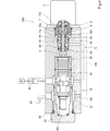
- FIG. 6 is a cross-sectional view of a control valve 200 according to the second embodiment.
- the fixed throttle 7 may be provided in the pilot spool 44 instead of the main spool 24.
- the fixed throttle 7 is formed by forming a small-diameter through hole in the pilot spool 44 that communicates the axial hole 53 with the second outlet communication space 17b so as to be aligned with the radial through hole 54 of the opening / closing portion 42 in the axial direction. Can be provided on the pilot spool 44.
- the axial hole 53 and the second outlet communication space 17b constitute the outlet path 6, and the axial hole 53 constitutes the bypass path 8. Also in this configuration, the circuit symbol can be expressed in the same manner as in FIG. 1, and the same effect as the first embodiment can be obtained.
- FIG. 7 is a cross-sectional view of a control valve 300 according to the third embodiment.
- the fixed throttle 7 may be provided in the housing 10 instead of the main spool 24 or the pilot spool 44.
- a through hole 18 x that is open to the pilot pressure chamber 4 is formed in the housing 10.
- the through hole 18 x extends from the pilot pressure chamber 4 to the radially outer peripheral side of the second bore 12 and does not interfere with the through hole 13 and the first bore 11.
- the through hole 18x opens to the outer surface of the housing 10, and this opening is connected to the piping member 19x.
- the piping member 19x is connected to the piping member 19b.
- the outlet path 6 branches at the bypass path 8 and the pilot pressure chamber 4 and joins the bypass path at the connection point of the piping members 19x and 19b. Also in this configuration, the circuit symbol can be expressed in the same manner as in FIG. 1, and the same effect as the first embodiment can be obtained.
- the solenoid 3 is a proportional solenoid
- the pilot spool 44 has a pilot pressure corresponding to the input current value in the pilot pressure chamber 4 at an opening corresponding to the input current value when the solenoid 3 is excited.
- the bypass path 8 is opened, and when the input current value is equal to or greater than the predetermined value (second predetermined value), the bypass path 8 is closed.
- the solenoid 3 may be an ON-OFF solenoid.
- the pilot spool is configured to close the inlet path when the solenoid is not excited to open the bypass path, and to open the inlet path when the solenoid is excited to generate pilot pressure and close the bypass path. . Even in this configuration, the same effects as those of the above embodiment can be obtained.
Landscapes
- Engineering & Computer Science (AREA)
- General Engineering & Computer Science (AREA)
- Mechanical Engineering (AREA)
- Physics & Mathematics (AREA)
- Fluid Mechanics (AREA)
- Fluid-Driven Valves (AREA)
- Magnetically Actuated Valves (AREA)
Priority Applications (2)
| Application Number | Priority Date | Filing Date | Title |
|---|---|---|---|
| US17/054,055 US11293560B2 (en) | 2018-05-07 | 2019-04-23 | Solenoid flow control valve |
| EP19799111.0A EP3792538B1 (en) | 2018-05-07 | 2019-04-23 | Solenoid flow control valve |
Applications Claiming Priority (2)
| Application Number | Priority Date | Filing Date | Title |
|---|---|---|---|
| JP2018-089388 | 2018-05-07 | ||
| JP2018089388A JP7011526B2 (ja) | 2018-05-07 | 2018-05-07 | 電磁流量制御弁 |
Publications (1)
| Publication Number | Publication Date |
|---|---|
| WO2019216193A1 true WO2019216193A1 (ja) | 2019-11-14 |
Family
ID=68468008
Family Applications (1)
| Application Number | Title | Priority Date | Filing Date |
|---|---|---|---|
| PCT/JP2019/017158 Ceased WO2019216193A1 (ja) | 2018-05-07 | 2019-04-23 | 電磁流量制御弁 |
Country Status (4)
| Country | Link |
|---|---|
| US (1) | US11293560B2 (enExample) |
| EP (1) | EP3792538B1 (enExample) |
| JP (1) | JP7011526B2 (enExample) |
| WO (1) | WO2019216193A1 (enExample) |
Cited By (1)
| Publication number | Priority date | Publication date | Assignee | Title |
|---|---|---|---|---|
| CN114382908A (zh) * | 2020-10-21 | 2022-04-22 | 通用电气航空系统有限责任公司 | 提升阀组件 |
Families Citing this family (2)
| Publication number | Priority date | Publication date | Assignee | Title |
|---|---|---|---|---|
| CN111237278B (zh) * | 2020-03-20 | 2025-01-21 | 星宇电子(宁波)有限公司 | 一种先导式开环控制比例流量阀 |
| JP7592003B2 (ja) | 2021-12-06 | 2024-11-29 | 株式会社クボタ | 作業車 |
Citations (3)
| Publication number | Priority date | Publication date | Assignee | Title |
|---|---|---|---|---|
| JPS61270573A (ja) * | 1985-05-27 | 1986-11-29 | Tokyo Keiki Co Ltd | 高速スプ−ル位置制御装置 |
| JPH081345Y2 (ja) * | 1989-03-29 | 1996-01-17 | 川崎重工業株式会社 | 電磁流量制御弁 |
| JPH081345U (ja) | 1993-10-25 | 1996-09-03 | 耕司郎 小野 | 硬貨入れ |
Family Cites Families (4)
| Publication number | Priority date | Publication date | Assignee | Title |
|---|---|---|---|---|
| US2638118A (en) * | 1949-11-05 | 1953-05-12 | Minnesota Automotive Inc | Control mechanism for preventing motor vehicles from creeping with provision for maintaining a constant restraining force |
| FR2647876B1 (fr) * | 1989-05-31 | 1991-08-23 | Bendix France | Modulateur et circuit de direction assistee comprenant un tel modulateur |
| US5836335A (en) * | 1991-08-19 | 1998-11-17 | Fluid Power Industries, Inc. | Proportional pressure control valve |
| LU88277A1 (de) * | 1993-05-27 | 1994-12-01 | Hydrolux Sarl | Vorgesteuertes Servoventil |
-
2018
- 2018-05-07 JP JP2018089388A patent/JP7011526B2/ja active Active
-
2019
- 2019-04-23 US US17/054,055 patent/US11293560B2/en active Active
- 2019-04-23 WO PCT/JP2019/017158 patent/WO2019216193A1/ja not_active Ceased
- 2019-04-23 EP EP19799111.0A patent/EP3792538B1/en active Active
Patent Citations (3)
| Publication number | Priority date | Publication date | Assignee | Title |
|---|---|---|---|---|
| JPS61270573A (ja) * | 1985-05-27 | 1986-11-29 | Tokyo Keiki Co Ltd | 高速スプ−ル位置制御装置 |
| JPH081345Y2 (ja) * | 1989-03-29 | 1996-01-17 | 川崎重工業株式会社 | 電磁流量制御弁 |
| JPH081345U (ja) | 1993-10-25 | 1996-09-03 | 耕司郎 小野 | 硬貨入れ |
Cited By (1)
| Publication number | Priority date | Publication date | Assignee | Title |
|---|---|---|---|---|
| CN114382908A (zh) * | 2020-10-21 | 2022-04-22 | 通用电气航空系统有限责任公司 | 提升阀组件 |
Also Published As
| Publication number | Publication date |
|---|---|
| EP3792538B1 (en) | 2023-10-11 |
| US11293560B2 (en) | 2022-04-05 |
| EP3792538A1 (en) | 2021-03-17 |
| EP3792538A4 (en) | 2022-02-09 |
| US20210215267A1 (en) | 2021-07-15 |
| JP2019196779A (ja) | 2019-11-14 |
| JP7011526B2 (ja) | 2022-01-26 |
Similar Documents
| Publication | Publication Date | Title |
|---|---|---|
| JP5592641B2 (ja) | 電気油圧ポペットパイロット弁によって操作されるポペット弁 | |
| JP6417353B2 (ja) | 減圧弁ユニット | |
| WO1993021447A1 (fr) | Soupape de commande a soupapes de compensation de pression | |
| WO2019216193A1 (ja) | 電磁流量制御弁 | |
| JP2015055334A (ja) | 流体圧制御装置 | |
| WO2018180367A1 (ja) | 電磁比例弁 | |
| JP6592300B2 (ja) | バイパス通路付きチェック弁を備えるソレノイドバルブ | |
| JP6190315B2 (ja) | パイロット式流量制御弁 | |
| JP2019196779A5 (enExample) | ||
| JP2019056464A (ja) | 流量制御弁 | |
| WO2019208047A1 (ja) | 電磁比例弁付きキャップ | |
| JP7325192B2 (ja) | 電磁弁及び作業機械 | |
| JP6572067B2 (ja) | 複合弁及びそれを用いたソレノイドバルブ | |
| JPH07317942A (ja) | 電磁弁 | |
| KR102859079B1 (ko) | 유량 제어 밸브 및 작업 기계 | |
| JP4145215B2 (ja) | 内燃機関用流体回路 | |
| JP5470180B2 (ja) | コントロールバルブ | |
| JP2019196777A (ja) | スプール弁 | |
| JP7336836B2 (ja) | 流量制御弁及び作業機械 | |
| JP4791823B2 (ja) | ロードセンシング方式の油圧制御装置に用いられる油圧制御弁 | |
| JP2003185044A (ja) | ラインリリーフ弁 | |
| JPH0557443B2 (enExample) | ||
| JP2025155044A (ja) | ポペット弁装置、及びそれを備える液圧駆動システム | |
| JP2000104842A (ja) | 圧力制御弁 | |
| JP2003294002A (ja) | 制御弁および液圧制御装置 |
Legal Events
| Date | Code | Title | Description |
|---|---|---|---|
| 121 | Ep: the epo has been informed by wipo that ep was designated in this application |
Ref document number: 19799111 Country of ref document: EP Kind code of ref document: A1 |
|
| NENP | Non-entry into the national phase |
Ref country code: DE |
|
| ENP | Entry into the national phase |
Ref document number: 2019799111 Country of ref document: EP Effective date: 20201207 |