WO2019208047A1 - 電磁比例弁付きキャップ - Google Patents
電磁比例弁付きキャップ Download PDFInfo
- Publication number
- WO2019208047A1 WO2019208047A1 PCT/JP2019/012206 JP2019012206W WO2019208047A1 WO 2019208047 A1 WO2019208047 A1 WO 2019208047A1 JP 2019012206 W JP2019012206 W JP 2019012206W WO 2019208047 A1 WO2019208047 A1 WO 2019208047A1
- Authority
- WO
- WIPO (PCT)
- Prior art keywords
- electromagnetic proportional
- cap
- proportional valve
- passage
- pilot
- Prior art date
Links
Images


Classifications
-
- G—PHYSICS
- G05—CONTROLLING; REGULATING
- G05D—SYSTEMS FOR CONTROLLING OR REGULATING NON-ELECTRIC VARIABLES
- G05D11/00—Control of flow ratio
- G05D11/02—Controlling ratio of two or more flows of fluid or fluent material
- G05D11/13—Controlling ratio of two or more flows of fluid or fluent material characterised by the use of electric means
-
- F—MECHANICAL ENGINEERING; LIGHTING; HEATING; WEAPONS; BLASTING
- F16—ENGINEERING ELEMENTS AND UNITS; GENERAL MEASURES FOR PRODUCING AND MAINTAINING EFFECTIVE FUNCTIONING OF MACHINES OR INSTALLATIONS; THERMAL INSULATION IN GENERAL
- F16K—VALVES; TAPS; COCKS; ACTUATING-FLOATS; DEVICES FOR VENTING OR AERATING
- F16K27/00—Construction of housing; Use of materials therefor
- F16K27/04—Construction of housing; Use of materials therefor of sliding valves
- F16K27/041—Construction of housing; Use of materials therefor of sliding valves cylindrical slide valves
-
- F—MECHANICAL ENGINEERING; LIGHTING; HEATING; WEAPONS; BLASTING
- F15—FLUID-PRESSURE ACTUATORS; HYDRAULICS OR PNEUMATICS IN GENERAL
- F15B—SYSTEMS ACTING BY MEANS OF FLUIDS IN GENERAL; FLUID-PRESSURE ACTUATORS, e.g. SERVOMOTORS; DETAILS OF FLUID-PRESSURE SYSTEMS, NOT OTHERWISE PROVIDED FOR
- F15B13/00—Details of servomotor systems ; Valves for servomotor systems
- F15B13/02—Fluid distribution or supply devices characterised by their adaptation to the control of servomotors
- F15B13/04—Fluid distribution or supply devices characterised by their adaptation to the control of servomotors for use with a single servomotor
- F15B13/042—Fluid distribution or supply devices characterised by their adaptation to the control of servomotors for use with a single servomotor operated by fluid pressure
- F15B13/043—Fluid distribution or supply devices characterised by their adaptation to the control of servomotors for use with a single servomotor operated by fluid pressure with electrically-controlled pilot valves
- F15B13/0433—Fluid distribution or supply devices characterised by their adaptation to the control of servomotors for use with a single servomotor operated by fluid pressure with electrically-controlled pilot valves the pilot valves being pressure control valves
-
- F—MECHANICAL ENGINEERING; LIGHTING; HEATING; WEAPONS; BLASTING
- F15—FLUID-PRESSURE ACTUATORS; HYDRAULICS OR PNEUMATICS IN GENERAL
- F15B—SYSTEMS ACTING BY MEANS OF FLUIDS IN GENERAL; FLUID-PRESSURE ACTUATORS, e.g. SERVOMOTORS; DETAILS OF FLUID-PRESSURE SYSTEMS, NOT OTHERWISE PROVIDED FOR
- F15B13/00—Details of servomotor systems ; Valves for servomotor systems
- F15B13/02—Fluid distribution or supply devices characterised by their adaptation to the control of servomotors
- F15B13/06—Fluid distribution or supply devices characterised by their adaptation to the control of servomotors for use with two or more servomotors
- F15B13/08—Assemblies of units, each for the control of a single servomotor only
- F15B13/0803—Modular units
- F15B13/0832—Modular valves
- F15B13/0842—Monoblock type valves, e.g. with multiple valve spools in a common housing
-
- F—MECHANICAL ENGINEERING; LIGHTING; HEATING; WEAPONS; BLASTING
- F15—FLUID-PRESSURE ACTUATORS; HYDRAULICS OR PNEUMATICS IN GENERAL
- F15B—SYSTEMS ACTING BY MEANS OF FLUIDS IN GENERAL; FLUID-PRESSURE ACTUATORS, e.g. SERVOMOTORS; DETAILS OF FLUID-PRESSURE SYSTEMS, NOT OTHERWISE PROVIDED FOR
- F15B13/00—Details of servomotor systems ; Valves for servomotor systems
- F15B13/02—Fluid distribution or supply devices characterised by their adaptation to the control of servomotors
- F15B13/06—Fluid distribution or supply devices characterised by their adaptation to the control of servomotors for use with two or more servomotors
- F15B13/08—Assemblies of units, each for the control of a single servomotor only
- F15B13/0803—Modular units
- F15B13/0871—Channels for fluid
-
- F—MECHANICAL ENGINEERING; LIGHTING; HEATING; WEAPONS; BLASTING
- F16—ENGINEERING ELEMENTS AND UNITS; GENERAL MEASURES FOR PRODUCING AND MAINTAINING EFFECTIVE FUNCTIONING OF MACHINES OR INSTALLATIONS; THERMAL INSULATION IN GENERAL
- F16K—VALVES; TAPS; COCKS; ACTUATING-FLOATS; DEVICES FOR VENTING OR AERATING
- F16K31/00—Actuating devices; Operating means; Releasing devices
- F16K31/12—Actuating devices; Operating means; Releasing devices actuated by fluid
- F16K31/42—Actuating devices; Operating means; Releasing devices actuated by fluid by means of electrically-actuated members in the supply or discharge conduits of the fluid motor
- F16K31/423—Actuating devices; Operating means; Releasing devices actuated by fluid by means of electrically-actuated members in the supply or discharge conduits of the fluid motor the actuated members consisting of multiple way valves
- F16K31/426—Actuating devices; Operating means; Releasing devices actuated by fluid by means of electrically-actuated members in the supply or discharge conduits of the fluid motor the actuated members consisting of multiple way valves the actuated valves being cylindrical sliding valves
-
- F—MECHANICAL ENGINEERING; LIGHTING; HEATING; WEAPONS; BLASTING
- F15—FLUID-PRESSURE ACTUATORS; HYDRAULICS OR PNEUMATICS IN GENERAL
- F15B—SYSTEMS ACTING BY MEANS OF FLUIDS IN GENERAL; FLUID-PRESSURE ACTUATORS, e.g. SERVOMOTORS; DETAILS OF FLUID-PRESSURE SYSTEMS, NOT OTHERWISE PROVIDED FOR
- F15B13/00—Details of servomotor systems ; Valves for servomotor systems
- F15B2013/002—Modular valves, i.e. consisting of an assembly of interchangeable components
- F15B2013/006—Modular components with multiple uses, e.g. kits for either normally-open or normally-closed valves, interchangeable or reprogrammable manifolds
-
- F—MECHANICAL ENGINEERING; LIGHTING; HEATING; WEAPONS; BLASTING
- F15—FLUID-PRESSURE ACTUATORS; HYDRAULICS OR PNEUMATICS IN GENERAL
- F15B—SYSTEMS ACTING BY MEANS OF FLUIDS IN GENERAL; FLUID-PRESSURE ACTUATORS, e.g. SERVOMOTORS; DETAILS OF FLUID-PRESSURE SYSTEMS, NOT OTHERWISE PROVIDED FOR
- F15B2211/00—Circuits for servomotor systems
- F15B2211/30—Directional control
- F15B2211/32—Directional control characterised by the type of actuation
- F15B2211/327—Directional control characterised by the type of actuation electrically or electronically
-
- F—MECHANICAL ENGINEERING; LIGHTING; HEATING; WEAPONS; BLASTING
- F15—FLUID-PRESSURE ACTUATORS; HYDRAULICS OR PNEUMATICS IN GENERAL
- F15B—SYSTEMS ACTING BY MEANS OF FLUIDS IN GENERAL; FLUID-PRESSURE ACTUATORS, e.g. SERVOMOTORS; DETAILS OF FLUID-PRESSURE SYSTEMS, NOT OTHERWISE PROVIDED FOR
- F15B2211/00—Circuits for servomotor systems
- F15B2211/30—Directional control
- F15B2211/32—Directional control characterised by the type of actuation
- F15B2211/329—Directional control characterised by the type of actuation actuated by fluid pressure
-
- F—MECHANICAL ENGINEERING; LIGHTING; HEATING; WEAPONS; BLASTING
- F15—FLUID-PRESSURE ACTUATORS; HYDRAULICS OR PNEUMATICS IN GENERAL
- F15B—SYSTEMS ACTING BY MEANS OF FLUIDS IN GENERAL; FLUID-PRESSURE ACTUATORS, e.g. SERVOMOTORS; DETAILS OF FLUID-PRESSURE SYSTEMS, NOT OTHERWISE PROVIDED FOR
- F15B2211/00—Circuits for servomotor systems
- F15B2211/30—Directional control
- F15B2211/355—Pilot pressure control
-
- F—MECHANICAL ENGINEERING; LIGHTING; HEATING; WEAPONS; BLASTING
- F15—FLUID-PRESSURE ACTUATORS; HYDRAULICS OR PNEUMATICS IN GENERAL
- F15B—SYSTEMS ACTING BY MEANS OF FLUIDS IN GENERAL; FLUID-PRESSURE ACTUATORS, e.g. SERVOMOTORS; DETAILS OF FLUID-PRESSURE SYSTEMS, NOT OTHERWISE PROVIDED FOR
- F15B2211/00—Circuits for servomotor systems
- F15B2211/60—Circuit components or control therefor
- F15B2211/635—Circuits providing pilot pressure to pilot pressure-controlled fluid circuit elements
- F15B2211/6355—Circuits providing pilot pressure to pilot pressure-controlled fluid circuit elements having valve means
-
- F—MECHANICAL ENGINEERING; LIGHTING; HEATING; WEAPONS; BLASTING
- F16—ENGINEERING ELEMENTS AND UNITS; GENERAL MEASURES FOR PRODUCING AND MAINTAINING EFFECTIVE FUNCTIONING OF MACHINES OR INSTALLATIONS; THERMAL INSULATION IN GENERAL
- F16K—VALVES; TAPS; COCKS; ACTUATING-FLOATS; DEVICES FOR VENTING OR AERATING
- F16K27/00—Construction of housing; Use of materials therefor
- F16K27/04—Construction of housing; Use of materials therefor of sliding valves
Definitions
- the present invention relates to a cap with an electromagnetic proportional valve.
- a control valve that controls the flow of hydraulic oil by controlling the pilot pressure with an electromagnetic proportional valve is known (see JP2010-127373A).
- JP2010-127373A an oil passage that communicates the pump and the electromagnetic proportional valve, an oil passage that communicates the electromagnetic proportional valve and the pilot chamber, an oil passage that communicates the electromagnetic proportional valve and the tank, Valve housing).
- the control valve described in JP2010-127373A is a specification that controls the pilot pressure by an electromagnetic proportional valve. Therefore, an oil passage that communicates the pump and the electromagnetic proportional valve, an oil passage that communicates the electromagnetic proportional valve and the pilot chamber, An oil passage communicating the proportional valve and the tank is provided in the valve housing in advance. On the other hand, in the case of a control valve having a specification that does not control pilot pressure by an electromagnetic proportional valve, the oil passage is not provided in the valve housing.
- an electromagnetic proportional valve is provided separately from the control valve, and the electromagnetic proportional valve and control valve are connected by piping, or the valve housing It was necessary to replace the oil path provided with the oil passage in advance, and the specification could not be easily changed.
- the present invention aims to easily change from a specification that does not control pilot pressure by a solenoid proportional valve to a specification that controls it.
- a cap with an electromagnetic proportional valve which is attached to a valve housing in which a spool is incorporated, defines a pilot chamber with the valve housing, and is attached to the pilot cap.
- An electromagnetic proportional valve that controls the pressure of the working fluid supplied to the pilot chamber, the pilot cap is a supply port to which a working fluid of a fluid pressure supply source is supplied, and a discharge for discharging the working fluid to the tank
- a drain passage for guiding the working fluid discharged from the electromagnetic proportional valve to the discharge port.
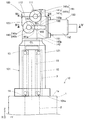
- FIG. 1 is a plan view of a cap with an electromagnetic proportional valve according to an embodiment of the present invention.
- FIG. 2 is a side view of the cap with an electromagnetic proportional valve as viewed from the direction II in FIG.
- FIG. 3 is a hydraulic circuit diagram including an electromagnetic proportional valve for supplying pilot pressure to the pilot chamber.
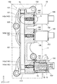
- 4 is a cross-sectional view of the cap with an electromagnetic proportional valve taken along line IV-IV in FIG.
- FIG. 5 is an enlarged cross-sectional view of a cap with an electromagnetic proportional valve in which the V portion of FIG. 4 is enlarged.
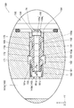
- FIG. 6 is a cross-sectional view of the cap with an electromagnetic proportional valve taken along line VI-VI in FIG.
- FIG. 1 is a plan view of a cap 100 with an electromagnetic proportional valve
- FIG. 2 is a side view of the cap 100 with an electromagnetic proportional valve as viewed from the direction II in FIG. 1 and 2, the valve housing 1 to which the cap 100 with an electromagnetic proportional valve is attached and the spool 2 provided in the valve housing 1 are indicated by a two-dot chain line.
- control valve 10 switches the supply and discharge of the working fluid to and from the actuator and controls the operation of the actuator.
- hydraulic oil used as the working fluid
- other fluids such as working water may be used as the working fluid.
- the control valve 10 includes a rectangular parallelepiped valve housing 1, a plurality of spools 2 slidably incorporated in the valve housing 1, and a cap 100 with an electromagnetic proportional valve provided with a plurality of pilot chambers 3 corresponding to the plurality of spools 2. And comprising.
- a cap 100 with an electromagnetic proportional valve is attached to a side surface 1a of the valve housing 1, and a pilot cap (hereinafter referred to as a cap) 101 that defines the pilot chamber 3 with the valve housing 1, and a cap 101 attached to the pilot chamber. 3, an electromagnetic proportional valve 150 that controls the pressure of the hydraulic oil to be supplied to 3.
- a plurality of electromagnetic proportional valves 150 are provided corresponding to the plurality of pilot chambers 3.
- the axial direction of the spool 2 that is, the central axis CL direction of the spool 2 and the direction in which the spool 2 moves is also referred to as the Z direction.
- the plurality of spools 2 and the plurality of pilot chambers 3 are arranged in a direction orthogonal to the axial direction of the spool 2.
- the arrangement direction of the spool 2, that is, the one direction orthogonal to the axial direction (Z direction) of the spool 2, that is, the arrangement direction of the pilot chamber 3 is also referred to as the X direction.
- a direction perpendicular to the width direction of the cap 101, that is, the axial direction (Z direction) of the spool 2 and the arrangement direction (X direction) of the spool 2 is also referred to as a Y direction.
- the cap 101 includes a cylindrical tubular portion 121 provided coaxially with the spool 2, a plurality of bolting portions 122 protruding radially outward from the tubular portion 121, and the axial direction (Z direction) of the spool 2 from the tubular portion 121. ) And a protruding end 123 protruding to the opposite side of the valve housing 1.
- the protruding end portion 123 is provided so as to connect the plurality of cylindrical portions 121.
- the cap 101 has an attachment surface 101a attached to the side surface 1a of the valve housing 1.
- the cap 101 is in the valve housing 1 in a state where the mounting surface 101 a of the cap 101 is in contact with the side surface 1 a of the valve housing 1. Fixed to.
- a pilot chamber 3 facing one end of the spool 2 is defined.
- a centering spring 12 as an urging member for applying a spring force to one end of the spool 2 is accommodated in the pilot chamber 3.
- a rod (spool end) 11 extending into the pilot chamber 3 is coupled to one end of the spool 2.
- a pair of spring receiving members 13 and 14 slidable along the outer periphery of the rod 11 are accommodated in the pilot chamber 3, and the centering spring 12 is interposed between the pair of spring receiving members 13 and 14.
- FIG. 3 is a hydraulic circuit diagram including an electromagnetic proportional valve 150 that supplies pilot pressure to the pilot chamber 3.
- the cap 101 discharges the hydraulic oil to a supply port 111 to which hydraulic oil discharged from the hydraulic pump 4 as a fluid pressure supply source is supplied and to a tank 5 in which the hydraulic oil is stored.
- Port 112 a primary pressure passage 141 that leads primary hydraulic fluid from the supply port 111 to the electromagnetic proportional valve 150, and a secondary pressure passage that leads hydraulic fluid reduced to the secondary pressure by the electromagnetic proportional valve 150 to the pilot chamber 3. 142, and a drain passage 143 that guides hydraulic oil discharged from the electromagnetic proportional valve 150 to the discharge port 112.
- the supply port 111 and the discharge port 112 are provided on a surface different from the mounting surface 101a.
- the supply port 111 and the discharge port 112 are provided side by side on one end face in the longitudinal direction (X direction) of the cap 101.
- the electromagnetic proportional valve 150 includes a valve body 151 (see FIGS. 4 and 5), a solenoid 152 that applies thrust to the valve body 151, and a valve body 151 in a direction that opposes the thrust of the solenoid 152. And a coil spring 153 as an urging member for applying an urging force.
- the electromagnetic proportional valve 150 controls the secondary pressure (pilot pressure) output to the pilot chamber 3 according to the control current supplied to the solenoid 152.
- the electromagnetic proportional valve 150 according to the present embodiment is a direct proportional pressure reducing valve that increases the secondary pressure as the current supplied to the solenoid 152 increases.
- the primary pressure passage 141 has a main primary pressure passage 141 a extending from the supply port 111 and a sub primary pressure passage 141 b having one end connected to the main primary pressure passage 141 a and the other end connected to the electromagnetic proportional valve 150. .
- a plurality of sub primary pressure passages 141 b are provided corresponding to each electromagnetic proportional valve 150.
- a plurality of secondary pressure passages 142 are provided corresponding to each electromagnetic proportional valve 150.
- the drain passage 143 includes a main drain passage 143a extending from the discharge port 112, and a sub-drain passage 143b having one end connected to the main drain passage 143a and the other end connected to the electromagnetic proportional valve 150.
- a plurality of auxiliary drain passages 143 b are provided corresponding to the respective electromagnetic proportional valves 150.
- the electromagnetic proportional valve 150 includes an input port 162p through which primary hydraulic fluid is guided from the primary pressure passage 141, an output port 163p through which secondary hydraulic fluid is guided to the secondary pressure passage 142, and a drain through the drain passage 143. And a drain port 161p.
- the communication between the input port 162p and the output port 163p is cut off, the closed position (C) where the output port 163p and the drain port 161p communicate with each other, the input port 162p and the output port 163p communicate with each other, It operates between the open position (O) where the communication between the output port 163p and the drain port 161p is blocked.
- the input port 162p communicates with both the output port 163p and the drain port 161p through a restriction.
- FIGS. 2 and 4 to 6 the configuration of the electromagnetic proportional valve 150 and the passages provided in the cap 101 will be described.
- 4 is a cross-sectional view of the cap 100 with an electromagnetic proportional valve taken along line IV-IV in FIG.
- FIG. 5 is an enlarged cross-sectional view of the cap 100 with an electromagnetic proportional valve in which the V portion in FIG. 4 is enlarged.
- 6 is a cross-sectional view of the cap 100 with an electromagnetic proportional valve taken along line VI-VI in FIG.
- the solenoid 152 is fixed to the cap 101 with a bolt 159.
- the solenoid 152 includes a coil 71 that generates a magnetic force according to a control current supplied from an external device, a fixed iron core (fixed core) 73 that is excited by the magnetic force of the coil 71, and a shaft that is attracted to the excited fixed iron core 73.
- a movable iron core (plunger) 72 that moves in the direction and a push rod 74 that is fixed to the movable iron core 72 and moves in the axial direction together with the movable iron core 72 are provided.
- a stopper portion 75 with which one end of the push rod 74 penetrating the movable iron core 72 comes into contact.
- the cap 101 has a storage chamber 160 for storing the valve body 151.
- the valve body 151 is in a direction (Y direction) orthogonal to each of the main primary pressure passages 141a extending in the axial direction (Z direction) of the spool 2 and the arrangement direction (X direction) of the spool 2. It is slidably provided.
- the solenoid 152 applies a thrust to one end (the right end in the figure) of the valve body 151, and the coil spring 153 applies a biasing force against the thrust by the solenoid 152 to the other end (the left end in the figure) of the valve body 151.
- the storage chamber 160 includes a first sliding portion 161 provided on the left end side of the storage chamber 160 in the drawing, a second sliding portion 162 provided on the right end side of the storage chamber 160 in the drawing, a first sliding portion 161 and a second sliding portion 161. And an annular recess 163 provided between the sliding portion 162.
- the first sliding portion 161, the second sliding portion 162, and the annular recess 163 are circular openings whose cross sections are centered on the central axis of the valve body 151.
- the inner diameter of the second sliding portion 162 is larger than the inner diameter of the first sliding portion 161, and the inner diameter of the annular recess 163 is larger than the inner diameter of the second sliding portion 162.
- the valve body 151 is a shaft-like member whose base end portion (right end portion in the drawing) is fixed to the push rod 74 of the solenoid 152.
- the valve body 151 includes a first land portion 171, a second land portion 172, and a third land portion 173 from the distal end side (the left end side in the drawing) of the valve body 151 toward the proximal end side (the right end side in the drawing). It is provided in order.
- Each land portion 171, 172, 173 protrudes radially outward.
- the land portions 171, 172, and 173 are provided apart from each other in the central axis direction (Y direction) of the valve body 151. Between each land part 171,172,173, it is set as the annular groove dented in radial direction inward.
- the first land portion 171 slides along the inner peripheral surface of the first sliding portion 161, and the second land portion 172 and the third land portion 173 move along the inner peripheral surface of the second sliding portion 162. Slide.
- the outer diameter of the second land portion 172 and the outer diameter of the third land portion 173 are the same.
- the outer diameters of the second and third land portions 172 and 173 are larger than the outer diameter of the first land portion 171.
- the second land portion 172 has a tapered portion 172t whose outer diameter gradually decreases from the sliding contact portion that is in sliding contact with the inner peripheral surface of the second sliding portion 162 toward the proximal end side of the valve body 151.
- the storage chamber 160 includes a drain chamber 183 defined by the first sliding portion 161 and the valve body 151, a primary pressure chamber 181 defined by the second sliding portion 162 and the valve body 151, and an annular recess. And a secondary pressure chamber 182 defined by the valve body 151 and the valve body 151.
- a rod chamber 164 into which the push rod 74 enters and exits is defined between the third land portion 173 and the solenoid 152.
- an input port 162 p that is an opening end portion of the sub primary pressure passage 141 b is provided on the inner peripheral surface of the second sliding portion 162.
- the primary pressure chamber 181 communicates with the primary pressure passage 141 through the input port 162p.
- An output port 163 p that is an open end portion of the secondary pressure passage 142 is provided on the bottom surface of the annular recess 163.
- the secondary pressure chamber 182 communicates with the secondary pressure passage 142 through the output port 163p.
- the support surface 161s of the coil spring 153 provided in the first sliding portion 161 is provided with a drain port 161p that is an open end portion of the sub drain passage 143b.
- the drain chamber 183 communicates with the drain passage 143 through the drain port 161p.
- the second land portion 172 constitutes a pressure receiving portion where the secondary pressure acts in the direction of arrow A.
- the direction of the arrow A is a direction in which the coil spring 153 biases the valve body 151 and is a direction against the thrust of the solenoid 152.
- the pressure receiving area of the second land portion 172 on which the secondary pressure acts is larger than the pressure receiving area of the first land portion 171. For this reason, the thrust by the secondary pressure, that is, the thrust of the pressure receiving area difference between the large-diameter second land portion 172 and the small-diameter first land portion 171 acts on the valve body 151 in the direction of arrow A.
- a coil spring 153 is accommodated in the first sliding portion 161.
- the first sliding portion 161 is provided so as to face the distal end surface of the valve body 151, and has a support surface 161 s that supports one end of the coil spring 153.
- the other end of the coil spring 153 is in contact with the spring receiving surface 151 s of the valve body 151.
- the coil spring 153 is interposed between the support surface 161s and the spring receiving surface 151s in a compressed state.
- the coil spring 153 contracts according to the amount of movement of the valve body 151, and applies an urging force according to the contraction amount (elastic deformation amount) from the natural length to the valve body 151. That is, the coil spring 153 biases the valve body 151 toward the solenoid 152 in the direction of arrow A.
- the thrust by the solenoid 152 acts on the valve body 151 in the direction of arrow B, and the urging force by the coil spring 153 and the thrust by the secondary pressure act in the direction of arrow A.
- the electromagnetic proportional valve 150 communicates the output port 163p with the input port 162p and the drain port 161p by the balance (balance) of the thrust Fs by the solenoid 152 with respect to the valve body 151, the biasing force Fk by the coil spring 153, and the thrust Fa by the secondary pressure. Is adjusted to control the secondary pressure (pilot pressure) output to the pilot chamber 3.
- the valve body 151 When the solenoid 152 is in a non-energized state in which no current flows, the valve body 151 is placed in the closed position (C), which is the initial position shown in FIG. In a state where the valve body 151 is disposed at the closed position (C), the push rod 74 is in contact with the stopper portion 75 in the case 70 of the solenoid 152. In the closed position (C), an initial load corresponding to the set length of the coil spring 153 acts on the valve body 151.
- the second land portion 172 is located in the second sliding portion 162, and the communication between the input port 162p and the output port 163p is blocked.
- the first land portion 171 is located outside the first sliding portion 161, and the output port 163p and the drain port 161p communicate with each other.
- the first land portion 171 has a closed position (C) that allows the flow of hydraulic oil from the output port 163p to the drain port 161p, and an open position that prohibits the flow of hydraulic oil from the output port 163p to the drain port 161p.
- C closed position
- O open position
- C closed position
- the valve body 151 is provided with an internal passage 155 having a longitudinal hole 155a penetrating in the axial direction and a lateral hole 155b penetrating in the radial direction.
- An opening facing the drain chamber 183 is provided on one end side of the vertical hole 155a.
- a horizontal hole 155 b is provided at the other end of the vertical hole 155 a, and an opening of the horizontal hole 155 b faces the rod chamber 164.
- the internal passage 155 communicates the drain chamber 183 and the rod chamber 164 regardless of the amount of movement of the valve body 151.
- the main primary pressure passage 141a extends linearly from the supply port 111 along a direction (X direction) orthogonal to the axial direction (Z direction) of the spool 2.
- the main primary pressure passage 141a is a through hole provided in a straight line by drilling or the like. An opening on one end side of the through hole is a supply port 111, and an opening on the other end side is closed by a plug.
- the sub-primary pressure passage 141b has a y-direction hole 141y provided linearly along the Y direction so as to pass through the main primary pressure passage 141a, and a linear shape along the Z direction so as to pass through the y-direction hole 141y.
- Z-direction hole 141z provided in the.
- the y-direction hole 141y and the z-direction hole 141z are provided by drilling or the like, and the opening ends of the y-direction hole 141y and the z-direction hole 141z are closed by plugs.
- the plurality of sub-primary pressure passages 141b communicate with the primary primary pressure passage 141a and the primary pressure chambers 181 provided corresponding to the plurality of electromagnetic proportional valves 150, respectively.
- the secondary pressure passage 142 extends linearly from the output port 163 p along the axial direction (Z direction) of the spool 2, and communicates the secondary pressure chamber 182 and the pilot chamber 3. .
- the main drain passage 143a extends linearly from the discharge port 112 along a direction (X direction) perpendicular to the axial direction (Z direction) of the spool 2.
- the main drain passage 143a is a through hole provided in a straight line by drilling or the like. The opening on one end side of the through hole is a discharge port 112, and the opening on the other end side is closed by a plug.
- the auxiliary drain passage 143b extends linearly along the central axis direction (Y direction) of the valve body 151.
- the plurality of sub drain passages 143 b communicate with the main drain passage 143 a and the drain chambers 183 provided corresponding to the plurality of electromagnetic proportional valves 150.
- the main primary pressure passage 141a and the main drain passage 143a can be used in common for the plurality of electromagnetic proportional valves 150.
- the cap 101 can be reduced in size compared with the case where a dedicated passage for communicating the supply port and the solenoid proportional valve is provided for each of the plurality of solenoid proportional valves.
- the main primary pressure passage 141a and the main drain passage 143a are provided in parallel to each other. Therefore, according to the present embodiment, the cap 101 can be further downsized as compared with the case where the main primary pressure passage 141a and the main drain passage 143a are not provided in parallel to each other.
- the main primary pressure passage 141 a and the main drain passage 143 a are positions where their center axes are shifted in the axial direction (Z direction) of the spool 2 and the axial direction (Y direction) of the valve body 151. Provided.
- the main primary pressure passage 141a and the main drain passage 143a are arranged such that the central axis of the main primary pressure passage 141a and the central axis of the main drain passage 143a overlap when viewed from the Z direction. Compared with the case where it is provided, the Z-direction dimension of the cap 101 can be reduced. Further, according to the present embodiment, the main primary pressure passage 141a and the main drain passage 143a are provided so that the central axis of the main primary pressure passage 141a and the central axis of the main drain passage 143a overlap each other when viewed from the Y direction. Compared with the case, the dimension of the cap 101 in the Y direction can be reduced. That is, in the present embodiment, the main primary pressure passage 141a and the main drain passage 143a are provided at positions shifted in the Y direction and the Z direction, so that the cap 101 can be further downsized.
- the main primary pressure passage 141a is disposed so as to face the pilot chamber 3 and the valve body 151
- the main drain passage 143a is disposed so as to face the solenoid 152 and the valve body 151.
- the valve body 151 is disposed between the pilot chamber 3 and the main primary pressure passage 141a and between the solenoid 152 and the main drain passage 143a.
- the dimension of the cap 101 in the Y direction is made smaller than when the main primary pressure passage 141a is provided on the left side of the main drain passage 143a.
- the cap 101 can be further downsized.
- the valve body 151 When the current is not applied to the coil 71 of the solenoid 152, the valve body 151 is urged in the direction of arrow A by the urging force of the coil spring 153, and is located at the closed position (C).
- the first land portion 171 In the closed position (C), the first land portion 171 is disposed between the first sliding portion 161 and the second sliding portion 162, and the output port 163p and the drain port 161p communicate with each other.
- the second land portion 172 is disposed in the second sliding portion 162, and communication between the input port 162p and the output port 163p is blocked. Therefore, the pressure (secondary pressure) in the pilot chamber 3 connected to the output port 163p is a tank pressure.
- the solenoid 152 gives a thrust Fs to the valve body 151 via the push rod 74 by an electromagnetic force corresponding to the current value flowing through the coil 71.
- the thrust Fs by the solenoid 152 with respect to the valve body 151 exceeds the urging force Fk by the coil spring 153, the valve body 151 moves in the other axial direction (direction of arrow B).
- the second land portion 172 is disposed between the first sliding portion 161 and the second sliding portion 162, and the input port 162p and the output port 163p communicate with each other.
- the 1st land part 171 is arrange
- the hydraulic oil introduced into the primary pressure chamber 181 from the input port 162p is guided to the secondary pressure chamber 182 through a gap between the outer peripheral surface of the valve body 151 and the inner peripheral surface of the second sliding portion 162.
- the gas is discharged from the output port 163p and led to the pilot chamber 3.
- the oil pressure corresponding to the pressure receiving area difference between the second land portion 172 and the first land portion 171 acts on the valve body 151 as a thrust Fa that presses the valve body 151 in the direction of arrow A. While the sum of the thrust Fa due to the secondary pressure and the biasing force Fk due to the coil spring 153 is smaller than the thrust Fs due to the solenoid 152, the valve body 151 moves in the direction of arrow B. That is, the opening area between the outer peripheral surface of the tapered portion 172t of the valve body 151 and the inner peripheral surface of the second sliding portion 162 increases, and the secondary pressure increases.
- the valve body 151 repeats the operation of reciprocating in the storage chamber 160 in the axial direction, and the inflow and discharge of the hydraulic oil are repeated in the pilot chamber 3. For this reason, the secondary pressure is controlled so that the thrust Fs by the solenoid 152 with respect to the valve body 151 and the urging force Fk by the coil spring 153 with respect to the valve body 151 and the thrust Fa by the secondary pressure are balanced. That is, the amount of hydraulic fluid leaked from the input port 162p to the output port 163p and the amount of hydraulic fluid leaked from the output port 163p to the drain port 161p are balanced to maintain the secondary pressure.
- the thrust Fs by the solenoid 152 is adjusted by the value of the control current supplied to the solenoid 152. For this reason, the secondary pressure (control pressure) output to the pilot chamber 3 is controlled by the value of the control current to the solenoid 152.
- the cap 101 guides the primary pressure passage 141 from the supply port 111 to the electromagnetic proportional valve 150 to the primary pressure passage 141 and the hydraulic fluid reduced to the secondary pressure by the electromagnetic proportional valve 150 to the pilot chamber 3.
- the secondary pressure passage 142 and the drain passage 143 that guides the hydraulic oil discharged from the electromagnetic proportional valve 150 to the discharge port 112 are provided.
- the pilot pressure is controlled by the electromagnetic proportional valve 150 by simply replacing the existing cap with the electromagnetic proportional valve-equipped cap 100 according to the present embodiment for a control valve that does not control the pilot pressure by the electromagnetic proportional valve 150.
- the specification can be changed. That is, according to the present embodiment, the electromagnetic proportional valve 150 can be easily changed from the specification that does not control the pilot pressure to the specification that controls it.
- the piping communicating with the hydraulic pump 4 and the tank 5 can be directly connected to the cap 101.
- the supply port 111 and the discharge port 112 are provided on the mounting surface 101a, it is necessary to provide a passage in the valve housing 1 that communicates with the supply port 111 and the discharge port 112, and the above-described specification change cannot be easily performed.
- the supply port 111 and the discharge port 112 are provided on a surface different from the mounting surface 101a, and therefore the valve housing 1 communicates with the supply port 111 and the discharge port 112. There is no need to provide a passage, and the electromagnetic proportional valve 150 can be easily changed to a specification for controlling the pilot pressure.
- the electromagnetic proportional valve 150 is a direct proportional pressure reducing valve that increases the secondary pressure as the current supplied to the solenoid 152 increases is described, but the present invention is not limited to this.
- the electromagnetic proportional valve 150 may be an inverse proportional pressure reducing valve that lowers the secondary pressure as the current supplied to the solenoid 152 increases.
- the cap with electromagnetic proportional valve 100 is attached to the valve housing 1 in which the spool 2 is incorporated.
- the pilot cap 101 that defines the pilot chamber 3 with the valve housing 1 is attached to the pilot cap 101 and supplied to the pilot chamber 3.
- An electromagnetic proportional valve 150 for controlling the pressure of the working fluid to be operated, and the pilot cap 101 discharges the working fluid to the supply port 111 to which the working fluid of the fluid pressure supply source (hydraulic pump 4) is supplied and the tank 5
- a drain that guides the working fluid discharged from the pressure passage 142 and the electromagnetic proportional valve 150 to the discharge port 112. It has a road 143, a.
- the pilot cap 101 has a primary pressure passage 141, a secondary pressure passage 142, and a drain passage 143.
- a control valve having a specification in which the pilot pressure is not controlled by the electromagnetic proportional valve 150 can be changed to a specification in which the pilot pressure is controlled by the electromagnetic proportional valve 150 by simply replacing the existing pilot cap with the pilot cap 101. it can. That is, it is possible to easily change from the specification not controlling the pilot pressure by the electromagnetic proportional valve 150 to the specification controlling it.
- the pilot cap 101 has an attachment surface 101a attached to the side surface 1a of the valve housing 1, and the supply port 111 and the discharge port 112 are provided on a different surface from the attachment surface 101a.
- the cap 100 with an electromagnetic proportional valve is provided with a plurality of pilot chambers 3, a plurality of electromagnetic proportional valves 150 are provided corresponding to the plurality of pilot chambers 3, and the electromagnetic proportional valve 150 includes a valve body 151, a valve body 151. And a biasing member (coil spring 153) that applies a biasing force in a direction opposite to the thrust of the solenoid 152 to the valve body 151, and the pilot cap 101 houses the valve body 151.
- the storage chamber 160 includes a primary pressure chamber 181 that communicates with the primary pressure passage 141, a secondary pressure chamber 182 that communicates with the secondary pressure passage 142, and a drain chamber 183 that communicates with the drain passage 143.
- a primary pressure passage 141 extending linearly from the supply port 111 along a direction perpendicular to the axial direction of the spool 2, and a main primary pressure passage 141a and a plurality of sub primary pressure passages 141b communicating with the primary pressure chambers 181 provided corresponding to each of the plurality of electromagnetic proportional valves 150, and the drain passage 143 is connected to the shaft of the spool 2 from the discharge port 112.
- a plurality of sub-drains communicating with a main drain passage 143a extending linearly along a direction orthogonal to the direction, and a drain chamber 183 provided corresponding to each of the main drain passage 143a and the plurality of electromagnetic proportional valves 150.
- a passage 143b is
- the pilot cap 101 can be downsized.
- the cap 100 with an electromagnetic proportional valve is provided so that the main primary pressure passage 141a and the main drain passage 143a are parallel to each other.
- the pilot cap 101 can be further downsized.
- the cap 100 with an electromagnetic proportional valve is provided such that the valve body 151 is slidable in a direction orthogonal to the axial direction of the spool 2 and the main primary pressure passage 141a.
- the main primary pressure passage 141a and the main drain passage 143a are These are provided at positions shifted in the axial direction of the spool 2 and the axial direction of the valve body 151.
- the main primary pressure passage 141a and the main drain passage 143a are provided at positions shifted in the axial direction of the spool 2 and the axial direction of the valve body 151, so that the pilot cap 101 can be further downsized.
- the cap 100 with an electromagnetic proportional valve is disposed so that the main primary pressure passage 141a faces the pilot chamber 3 with the valve body 151 interposed therebetween, and the main drain passage 143a faces the solenoid 152 with the valve body 151 interposed therebetween. Placed in.
- the pilot cap 101 can be further downsized.
Landscapes
- Engineering & Computer Science (AREA)
- General Engineering & Computer Science (AREA)
- Mechanical Engineering (AREA)
- Physics & Mathematics (AREA)
- Fluid Mechanics (AREA)
- General Physics & Mathematics (AREA)
- Automation & Control Theory (AREA)
- Magnetically Actuated Valves (AREA)
- Valve Housings (AREA)
- Fluid-Driven Valves (AREA)
Abstract
電磁比例弁付きキャップ(100)は、バルブハウジング(1)に取り付けられ、パイロット室(3)を画成するパイロットキャップ(101)と、パイロットキャップ(101)に取り付けられ、パイロット室(3)へ供給する作動流体の圧力を制御する電磁比例弁(150)と、を備え、パイロットキャップ(101)が、流体圧供給源(4)の作動流体が供給される供給ポート(111)と、タンク(5)に作動流体を排出する排出ポート(112)と、供給ポート(111)から電磁比例弁(150)に一次圧の作動流体を導く一次圧通路(141)と、電磁比例弁(150)により二次圧に減圧された作動流体をパイロット室(3)に導く二次圧通路(142)と、電磁比例弁(150)から排出される作動流体を排出ポート(112)に導くドレン通路(143)と、を有する。
Description
本発明は、電磁比例弁付きキャップに関する。
電磁比例弁によりパイロット圧を制御することにより、作動油の流れを制御する制御弁が知られている(JP2010-127373A参照)。JP2010-127373Aに記載の制御弁では、ポンプと電磁比例弁とを連通する油路、電磁比例弁とパイロット室とを連通する油路、電磁比例弁とタンクとを連通する油路が、ボディ(バルブハウジング)に設けられている。
JP2010-127373Aに記載の制御弁では、電磁比例弁によりパイロット圧を制御する仕様であるため、ポンプと電磁比例弁とを連通する油路、電磁比例弁とパイロット室とを連通する油路、電磁比例弁とタンクとを連通する油路が、予めバルブハウジングに設けられている。一方、電磁比例弁によりパイロット圧を制御しない仕様の制御弁の場合、バルブハウジングには、上記油路が設けられない。
このため、後から電磁比例弁によりパイロット圧を制御する仕様に変更する場合、制御弁とは別置きの電磁比例弁を設け、電磁比例弁と制御弁とを配管により接続したり、バルブハウジングを予め上記油路が設けられたものに交換したりする必要があり、仕様変更を容易に行うことができなかった。
本発明は、電磁比例弁によりパイロット圧を制御しない仕様から制御する仕様への変更を容易に行うことを目的とする。
本発明のある態様によれば、電磁比例弁付きキャップであって、スプールが組み込まれたバルブハウジングに取り付けられ、前記バルブハウジングとでパイロット室を画成するパイロットキャップと、前記パイロットキャップに取り付けられ、前記パイロット室へ供給する作動流体の圧力を制御する電磁比例弁と、を備え、前記パイロットキャップは、流体圧供給源の作動流体が供給される供給ポートと、タンクに作動流体を排出する排出ポートと、前記供給ポートから前記電磁比例弁に一次圧の作動流体を導く一次圧通路と、前記電磁比例弁により二次圧に減圧された作動流体を前記パイロット室に導く二次圧通路と、前記電磁比例弁から排出される作動流体を前記排出ポートに導くドレン通路と、を有する。
図面を参照して、本発明の実施形態に係る電磁比例弁付きキャップを備えた制御弁について説明する。図1は電磁比例弁付きキャップ100の平面図であり、図2は図1のII方向から見た電磁比例弁付きキャップ100の側面図である。図1及び図2において、電磁比例弁付きキャップ100が取り付けられるバルブハウジング1、及びバルブハウジング1内に設けられるスプール2については、二点鎖線で示す。
図1及び図2に示すように、制御弁10は、アクチュエータに対する作動流体の給排を切り換え、アクチュエータの動作を制御するものである。作動流体として作動油を用いる例について説明するが、作動水等の他の流体を作動流体として用いてもよい。
制御弁10は、直方体形状のバルブハウジング1と、バルブハウジング1に摺動自在に組み込まれる複数のスプール2と、複数のスプール2に対応する複数のパイロット室3が設けられる電磁比例弁付きキャップ100と、を備える。
電磁比例弁付きキャップ100は、バルブハウジング1の側面1aに取り付けられ、バルブハウジング1とでパイロット室3を画成するパイロットキャップ(以下、キャップと記す)101と、キャップ101に取り付けられ、パイロット室3へ供給する作動油の圧力を制御する電磁比例弁150と、を備える。電磁比例弁150は、複数のパイロット室3に対応して複数設けられる。
なお、以下の説明では、スプール2の軸方向、すなわちスプール2の中心軸CL方向であってスプール2が移動する方向をZ方向とも記す。また、複数のスプール2及び複数のパイロット室3は、スプール2の軸方向に直交する方向に配列される。このため、スプール2の軸方向(Z方向)に直交する一方向であるスプール2の配列方向、すなわちパイロット室3の配列方向をX方向とも記す。さらに、キャップ101の幅方向、すなわちスプール2の軸方向(Z方向)及びスプール2の配列方向(X方向)のそれぞれに直交する方向をY方向とも記す。
キャップ101は、スプール2と同軸に設けられる円筒状の筒部121と、筒部121から径方向外方に突出する複数のボルト止め部122と、筒部121からスプール2の軸方向(Z方向)に沿って、バルブハウジング1とは反対側に突出する突出端部123と、を有する。突出端部123は、複数の筒部121を連結するように設けられる。
キャップ101は、バルブハウジング1の側面1aに取り付けられる取付面101aを有する。ボルト止め部122にボルトが挿通され、バルブハウジング1のねじ部にボルトがねじ込まれることにより、キャップ101の取付面101aがバルブハウジング1の側面1aに当接した状態で、キャップ101がバルブハウジング1に固定される。
図2に示すように、キャップ101がバルブハウジング1に取り付けられることにより、スプール2の一端が臨むパイロット室3が画成される。パイロット室3内には、スプール2の一端にばね力を付与する付勢部材としてのセンタリングスプリング12が収装される。スプール2の一端にはパイロット室3内に延在するロッド(スプールエンド)11が結合される。パイロット室3内にはロッド11の外周に沿って摺動可能な一対のばね受部材13,14が収容され、センタリングスプリング12は一対のばね受部材13,14の間に介装される。
図3を参照して、電磁比例弁付きキャップ100における油圧回路の構成について説明する。図3は、パイロット室3へパイロット圧を供給する電磁比例弁150を含む油圧回路図である。
図3に示すように、キャップ101は、流体圧供給源としての油圧ポンプ4から吐出される作動油が供給される供給ポート111と、作動油が貯留されるタンク5に作動油を排出する排出ポート112と、供給ポート111から電磁比例弁150に一次圧の作動油を導く一次圧通路141と、電磁比例弁150により二次圧に減圧された作動油をパイロット室3に導く二次圧通路142と、電磁比例弁150から排出される作動油を排出ポート112に導くドレン通路143と、を有する。
図2に示すように、供給ポート111及び排出ポート112は、取付面101aとは異なる面に設けられる。本実施形態では、キャップ101の長手方向(X方向)の一端面に、供給ポート111と排出ポート112とが並んで設けられる。
図3に示すように、電磁比例弁150は、弁体151(図4及び図5参照)と、弁体151に推力を与えるソレノイド152と、弁体151にソレノイド152の推力に対抗する方向の付勢力を与える付勢部材としてのコイルばね153と、を有する。
電磁比例弁150は、ソレノイド152に供給される制御電流に応じて、パイロット室3へ出力する二次圧(パイロット圧)を制御する。本実施形態に係る電磁比例弁150は、ソレノイド152に供給される電流が高くなるほど、二次圧を上昇させる正比例型の減圧弁である。
一次圧通路141は、供給ポート111から延在する主一次圧通路141aと、一端が主一次圧通路141aに接続され他端が電磁比例弁150に接続される副一次圧通路141bと、を有する。副一次圧通路141bは、各電磁比例弁150に対応して複数設けられる。二次圧通路142は、各電磁比例弁150に対応して複数設けられる。
ドレン通路143は、排出ポート112から延在する主ドレン通路143aと、一端が主ドレン通路143aに接続され他端が電磁比例弁150に接続される副ドレン通路143bと、を有する。副ドレン通路143bは、各電磁比例弁150に対応して複数設けられる。
電磁比例弁150は、一次圧通路141から一次圧の作動油が導かれる入力ポート162pと、二次圧通路142に二次圧の作動油を導く出力ポート163pと、ドレン通路143にドレンを導くドレンポート161pと、を有する。
電磁比例弁150は、入力ポート162pと出力ポート163pとの連通が遮断され、出力ポート163pとドレンポート161pとが連通する閉位置(C)と、入力ポート162pと出力ポート163pとが連通し、出力ポート163pとドレンポート161pとの連通が遮断される開位置(O)と、の間で動作する。閉位置(C)と開位置(O)との間の中間位置では、入力ポート162pが出力ポート163p及びドレンポート161pの双方に絞りを通じて連通する。
図2、図4~図6を参照して、電磁比例弁150及びキャップ101内に設けられる通路の構成について説明する。図4は、図2のIV-IV線に沿う電磁比例弁付きキャップ100の断面図であり、電磁比例弁150の構成を示す。図5は、図4のV部を拡大した電磁比例弁付きキャップ100の拡大断面図である。図6は、図2のVI-VI線に沿う電磁比例弁付きキャップ100の断面図である。
図4に示すように、ソレノイド152は、ボルト159によりキャップ101に固定される。ソレノイド152は、外部装置から供給される制御電流に応じて磁力を発生するコイル71と、コイル71の磁力によって励磁される固定鉄心(固定コア)73と、励磁された固定鉄心73に吸引され軸方向に移動する可動鉄心(プランジャ)72と、可動鉄心72に固着され可動鉄心72とともに軸方向に移動するプッシュロッド74と、を備える。ソレノイド152のケース70内には、可動鉄心72を貫通するプッシュロッド74の一端が当接するストッパ部75が設けられる。
図4及び図5に示すように、キャップ101は、弁体151を収容する収容室160を有する。弁体151は、収容室160内において、スプール2の軸方向(Z方向)及びスプール2の配列方向(X方向)に延在する主一次圧通路141aのそれぞれに直交する方向(Y方向)に摺動自在に設けられる。ソレノイド152は、弁体151の一端部(図示右端部)に推力を与え、コイルばね153は、弁体151の他端部(図示左端部)にソレノイド152による推力に抗した付勢力を与える。
収容室160は、収容室160の図示左端側に設けられる第1摺動部161と、収容室160の図示右端側に設けられる第2摺動部162と、第1摺動部161と第2摺動部162との間に設けられる環状凹部163と、を有する。第1摺動部161、第2摺動部162及び環状凹部163は、その断面が弁体151の中心軸を中心とする円形状の開口とされる。第2摺動部162の内径は第1摺動部161の内径よりも大きく、環状凹部163の内径は第2摺動部162の内径よりも大きい。
弁体151は、基端部(図示右端部)がソレノイド152のプッシュロッド74に固定される軸状部材である。弁体151には、第1ランド部171、第2ランド部172、第3ランド部173が、弁体151の先端側(図示左端側)から基端側(図示右端側)に向かって、この順に設けられる。各ランド部171,172,173は、径方向外方に突出する。各ランド部171,172,173は、弁体151の中心軸方向(Y方向)に互いに離間して設けられる。各ランド部171,172,173間は、径方向内方に窪む環状溝とされる。
第1ランド部171は、第1摺動部161の内周面に沿って摺動し、第2ランド部172及び第3ランド部173は、第2摺動部162の内周面に沿って摺動する。第2ランド部172の外径と第3ランド部173の外径は同一である。第2、第3ランド部172,173の外径は、第1ランド部171の外径よりも大きい。第2ランド部172は、第2摺動部162の内周面に摺接する摺接部から弁体151の基端側に向かって徐々に外径が小さくなるテーパ部172tを有する。
収容室160は、第1摺動部161と弁体151とによって画成されるドレン室183と、第2摺動部162と弁体151とによって画成される一次圧室181と、環状凹部163と弁体151とによって画成される二次圧室182と、を有する。なお、第3ランド部173とソレノイド152との間には、プッシュロッド74が出入りするロッド室164が画成される。
図2及び図5に示すように、第2摺動部162の内周面には、副一次圧通路141bの開口端部である入力ポート162pが設けられる。これにより、一次圧室181は、入力ポート162pを通じて一次圧通路141に連通する。環状凹部163の底面には、二次圧通路142の開口端部である出力ポート163pが設けられる。これにより、二次圧室182は、出力ポート163pを通じて二次圧通路142に連通する。第1摺動部161に設けられるコイルばね153の支持面161sには、副ドレン通路143bの開口端部であるドレンポート161pが設けられる。これにより、ドレン室183は、ドレンポート161pを通じてドレン通路143に連通する。
図5に示すように、第2ランド部172は、二次圧が矢印Aの方向に作用する受圧部を構成する。矢印Aの方向とは、コイルばね153が弁体151を付勢する方向であって、ソレノイド152の推力に抗する方向である。
第1ランド部171が第1摺動部161に位置した状態では、二次圧が作用する第2ランド部172の受圧面積が、第1ランド部171の受圧面積よりも大きい。このため、弁体151には、二次圧による推力、すなわち大径の第2ランド部172と小径の第1ランド部171の受圧面積差分の推力が、矢印Aの方向に向かって作用する。
第1摺動部161には、コイルばね153が収容される。第1摺動部161は、弁体151の先端面に対向するように設けられ、コイルばね153の一端を支持する支持面161sを有している。コイルばね153の他端は弁体151のばね受け面151sに当接している。コイルばね153は、支持面161sとばね受け面151sとの間に圧縮した状態で介装される。コイルばね153は、弁体151の移動量に応じて収縮し、自然長からの収縮量(弾性変形量)に応じた付勢力を弁体151に付与する。つまり、コイルばね153は、弁体151をソレノイド152に向けて、矢印Aの方向に付勢する。
このように、弁体151には、ソレノイド152による推力が矢印Bの方向に作用し、コイルばね153による付勢力及び二次圧による推力が矢印Aの方向に作用する。
電磁比例弁150は、弁体151に対するソレノイド152による推力Fs、コイルばね153による付勢力Fk及び二次圧による推力Faのバランス(釣り合い)によって、入力ポート162p及びドレンポート161pに対する出力ポート163pの連通を調整することにより、パイロット室3に出力する二次圧(パイロット圧)を制御する。
ソレノイド152に電流が流れていない非通電状態のときには、コイルばね153の付勢力によって弁体151が、図5に示す初期位置である閉位置(C)に配置される。弁体151が閉位置(C)に配置された状態では、プッシュロッド74がソレノイド152のケース70内のストッパ部75に当接している。閉位置(C)では、コイルばね153のセット長に応じた初期荷重が弁体151に作用する。
弁体151が閉位置(C)に配置されている状態では、第2ランド部172が第2摺動部162内に位置し、入力ポート162pと出力ポート163pとの連通を遮断する。このとき、第1ランド部171が第1摺動部161外に位置し、出力ポート163pとドレンポート161pとが連通する。
ソレノイド152に電流が流れると、ソレノイド152による推力が発生し、弁体151が図示左方に移動する。弁体151が開位置(O)に配置された状態では、第2ランド部172が第2摺動部162外に位置し、入力ポート162pと出力ポート163pとが連通する。このとき、第1ランド部171が第1摺動部161内に位置し、出力ポート163pとドレンポート161pとの連通を遮断する。
つまり、第1ランド部171は、出力ポート163pからドレンポート161pへの作動油の流れを許容する閉位置(C)と、出力ポート163pからドレンポート161pへの作動油の流れを禁止する開位置(O)との間で移動する。第2ランド部172は、入力ポート162pから出力ポート163pへの作動油の流れを許容する開位置(O)と、入力ポート162pから出力ポート163pへの作動油の流れを禁止する閉位置(C)との間で移動する。
弁体151には、軸方向に貫通する縦孔155aと径方向に貫通する横孔155bとを有する内部通路155が設けられる。縦孔155aの一端側には、ドレン室183に臨む開口部が設けられる。縦孔155aの他端には横孔155bが設けられ、横孔155bの開口部がロッド室164に臨む。内部通路155は、弁体151の移動量にかかわらず、ドレン室183とロッド室164とを連通する。
図2及び図6に示すように、主一次圧通路141aは、供給ポート111からスプール2の軸方向(Z方向)に直交する方向(X方向)に沿って直線状に延在する。主一次圧通路141aは、ドリル加工等により直線状に設けられた貫通孔であり、貫通孔の一端側の開口は供給ポート111とされ、他端側の開口はプラグによって閉止されている。
副一次圧通路141bは、主一次圧通路141aを貫通するようにY方向に沿って直線状に設けられたy方向孔141yと、y方向孔141yを貫通するようにZ方向に沿って直線状に設けられたz方向孔141zと、を有する。y方向孔141y及びz方向孔141zは、ドリル加工等により設けられ、y方向孔141y及びz方向孔141zの開口端部はプラグによって閉止されている。
複数の副一次圧通路141bは、主一次圧通路141aと複数の電磁比例弁150のそれぞれに対応して設けられる一次圧室181とを連通する。
図2に示すように、二次圧通路142は、出力ポート163pからスプール2の軸方向(Z方向)に沿って直線状に延在し、二次圧室182とパイロット室3とを連通する。
図2、図4及び図5に示すように、主ドレン通路143aは、排出ポート112からスプール2の軸方向(Z方向)に直交する方向(X方向)に沿って直線状に延在する。主ドレン通路143aは、ドリル加工等により直線状に設けられた貫通孔であり、貫通孔の一端側の開口は排出ポート112とされ、他端側の開口はプラグによって閉止されている。
副ドレン通路143bは、弁体151の中心軸方向(Y方向)に沿って直線状に延在する。複数の副ドレン通路143bは、主ドレン通路143aと複数の電磁比例弁150のそれぞれに対応して設けられるドレン室183とを連通する。
このように、本実施形態では、複数の電磁比例弁150に対して主一次圧通路141a及び主ドレン通路143aを共通に用いることができる。このため、本実施形態によれば、複数の電磁比例弁ごとに供給ポートと電磁比例弁とを連通する専用通路を設ける場合に比べて、キャップ101を小型化できる。
主一次圧通路141a及び主ドレン通路143aは、互いに平行となるように設けられる。したがって、本実施形態によれば、主一次圧通路141aと主ドレン通路143aとが互いに平行に設けられない場合に比べてキャップ101をより小型化できる。
図2に示すように、主一次圧通路141aと主ドレン通路143aとは、互いの中心軸が、スプール2の軸方向(Z方向)及び弁体151の軸方向(Y方向)にずれた位置に設けられる。
したがって、本実施形態によれば、主一次圧通路141aの中心軸と主ドレン通路143aの中心軸とが、Z方向から見たときに重なるように主一次圧通路141aと主ドレン通路143aとが設けられる場合に比べてキャップ101のZ方向寸法を小さくできる。また、本実施形態によれば、主一次圧通路141aの中心軸と主ドレン通路143aの中心軸とが、Y方向から見て重なるように主一次圧通路141aと主ドレン通路143aとが設けられる場合に比べてキャップ101のY方向寸法を小さくできる。つまり、本実施形態では、主一次圧通路141aと主ドレン通路143aとがY方向及びZ方向にずれた位置に設けられるので、キャップ101をより小型化できる。
主一次圧通路141aは、パイロット室3と弁体151を挟んで対向するように配置され、主ドレン通路143aは、ソレノイド152と弁体151を挟んで対向するように配置される。換言すれば、パイロット室3と主一次圧通路141aとの間であって、ソレノイド152と主ドレン通路143aとの間に弁体151が配置される。
したがって、本実施形態によれば、例えば、図2において、主一次圧通路141aが、主ドレン通路143aよりも図示左側に位置するように設けられる場合に比べて、キャップ101のY方向寸法を小さくでき、キャップ101をより小型化できる。
電磁比例弁150の動作について説明する。
ソレノイド152のコイル71に電流が通電されていない状態では、弁体151は、コイルばね153による付勢力によって矢印Aの方向に付勢され、閉位置(C)に位置する。閉位置(C)では、第1ランド部171が、第1摺動部161と第2摺動部162との間に配置され、出力ポート163pとドレンポート161pとが連通している。一方、第2ランド部172は、第2摺動部162内に配置されており、入力ポート162pと出力ポート163pとの連通は遮断されている。したがって、出力ポート163pに接続されるパイロット室3の圧力(二次圧)は、タンク圧となっている。
ソレノイド152のコイル71に制御電流が供給されると、コイル71の周囲に発生した磁界によって固定鉄心73が励磁され、可動鉄心72は固定鉄心73に向けて軸方向に引き寄せられる。ソレノイド152は、コイル71を流れる電流値に応じた電磁力により、プッシュロッド74を介して弁体151に対して推力Fsを与える。弁体151に対するソレノイド152による推力Fsが、コイルばね153による付勢力Fkを上回ると、弁体151が軸方向他方(矢印Bの方向)へと移動する。
これにより、第2ランド部172が、第1摺動部161と第2摺動部162との間に配置され、入力ポート162pと出力ポート163pとが連通する。一方、第1ランド部171が、第1摺動部161内に配置され、出力ポート163pとドレンポート161pとの連通が遮断される。
したがって、入力ポート162pから一次圧室181に導入される作動油は、弁体151の外周面と第2摺動部162の内周面との間の隙間を通じて、二次圧室182に導かれ、出力ポート163pから排出され、パイロット室3へと導かれる。パイロット室3に作動油が供給されることにより、パイロット室3内の圧力、すなわち二次圧が上昇する。
弁体151には、二次圧によって、第2ランド部172と第1ランド部171の受圧面積差分の油圧力が、弁体151を矢印Aの方向に押圧する推力Faとして作用する。二次圧による推力Faとコイルばね153による付勢力Fkとの和が、ソレノイド152による推力Fsよりも小さい間は、弁体151は矢印Bの方向へと移動する。つまり、弁体151のテーパ部172tの外周面と第2摺動部162の内周面との間の開口面積が増加し、二次圧が上昇する。
二次圧が上昇し、二次圧による推力Faとコイルばね153による付勢力Fkとの和が、ソレノイド152による推力Fsよりも大きくなると、弁体151は矢印Aの方向に押し戻される。これにより、第2ランド部172が第2摺動部162内に戻るとともに、第1ランド部171が第1摺動部161と第2摺動部162との間に戻る。これにより、入力ポート162pと出力ポート163pとの連通が遮断され、出力ポート163pとドレンポート161pとが再び連通する。したがって、パイロット室3の作動油は、出力ポート163p及びドレンポート161pを通じてタンク5に排出され、二次圧が低下する。
弁体151は、収容室160内を軸方向に往復するような動作を繰り返し、パイロット室3内には作動油の流入、排出が繰り返される。このため、二次圧は、弁体151に対するソレノイド152による推力Fsと、弁体151に対するコイルばね153による付勢力Fk及び二次圧による推力Faと、が釣り合うように制御される。つまり、入力ポート162pから出力ポート163pへの作動油の漏れ量と、出力ポート163pからドレンポート161pへの作動油の漏れ量とがバランスして二次圧が保持される。
ソレノイド152への制御電流の供給が停止すると、ソレノイド152が消磁され、ソレノイド152による推力Fsが無くなる。このため、弁体151は、コイルばね153の付勢力Fk及び二次圧による推力Faによって矢印Aの方向へと移動し、プッシュロッド74がストッパ部75に当接した状態の閉位置(C)へ戻る。閉位置(C)では、出力ポート163pとドレンポート161pとが連通するので、パイロット室3の圧力(二次圧)はタンク圧P0まで低下する。
ソレノイド152による推力Fsは、ソレノイド152へ供給する制御電流の値によって調整される。このため、パイロット室3へ出力する二次圧(制御圧)は、ソレノイド152への制御電流の値によって制御される。
上述した実施形態によれば、次の作用効果を奏する。
(1)キャップ101は、供給ポート111から電磁比例弁150に一次圧の作動油を導く一次圧通路141と、電磁比例弁150により二次圧に減圧された作動油をパイロット室3に導く二次圧通路142と、電磁比例弁150から排出される作動油を排出ポート112に導くドレン通路143と、を有する。このため、電磁比例弁150によりパイロット圧を制御しない仕様の制御弁に対し、既設のキャップを本実施形態に係る電磁比例弁付きキャップ100に交換するだけで、電磁比例弁150によりパイロット圧を制御する仕様へ変更することができる。つまり、本実施形態によれば、電磁比例弁150によりパイロット圧を制御しない仕様から制御する仕様への変更を容易に行うことができる。
(2)供給ポート111及び排出ポート112が取付面101aとは異なる面に設けられているので、油圧ポンプ4及びタンク5に連通する配管をキャップ101に直接接続することができる。取付面101aに供給ポート111及び排出ポート112を設ける場合、バルブハウジング1に、供給ポート111及び排出ポート112に連通する通路を設ける必要があり、上記仕様変更を容易に行うことができない。これに対して、本実施形態では、上述のとおり、供給ポート111及び排出ポート112が取付面101aとは異なる面に設けられているので、バルブハウジング1に供給ポート111及び排出ポート112に連通する通路を設ける必要がなく、電磁比例弁150によりパイロット圧を制御する仕様への変更を容易に行うことができる。
次のような変形例も本発明の範囲内であり、変形例に示す構成と上述の実施形態で説明した構成を組み合わせたり、以下の異なる変形例で説明する構成同士を組み合わせたりすることも可能である。
<変形例1>
上記実施形態では、キャップ101に複数のパイロット室3及び複数の電磁比例弁150が設けられる例について説明したが、本発明はこれに限定されない。キャップ101に単一のパイロット室3及び単一の電磁比例弁150が設けられる場合に本発明を適用することもできる。
上記実施形態では、キャップ101に複数のパイロット室3及び複数の電磁比例弁150が設けられる例について説明したが、本発明はこれに限定されない。キャップ101に単一のパイロット室3及び単一の電磁比例弁150が設けられる場合に本発明を適用することもできる。
<変形例2>
上記実施形態では、電磁比例弁150が、ソレノイド152に供給される電流が高くなるほど、二次圧を上昇させる正比例型の減圧弁である例について説明したが、本発明はこれに限定されない。電磁比例弁150は、ソレノイド152に供給される電流が高くなるほど、二次圧を低下させる逆比例型の減圧弁であってもよい。
上記実施形態では、電磁比例弁150が、ソレノイド152に供給される電流が高くなるほど、二次圧を上昇させる正比例型の減圧弁である例について説明したが、本発明はこれに限定されない。電磁比例弁150は、ソレノイド152に供給される電流が高くなるほど、二次圧を低下させる逆比例型の減圧弁であってもよい。
以上のように構成された本発明の実施形態の構成、作用、および効果をまとめて説明する。
電磁比例弁付きキャップ100は、スプール2が組み込まれたバルブハウジング1に取り付けられ、バルブハウジング1とでパイロット室3を画成するパイロットキャップ101と、パイロットキャップ101に取り付けられ、パイロット室3へ供給する作動流体の圧力を制御する電磁比例弁150と、を備え、パイロットキャップ101が、流体圧供給源(油圧ポンプ4)の作動流体が供給される供給ポート111と、タンク5に作動流体を排出する排出ポート112と、供給ポート111から電磁比例弁150に一次圧の作動流体を導く一次圧通路141と、電磁比例弁150により二次圧に減圧された作動流体をパイロット室3に導く二次圧通路142と、電磁比例弁150から排出される作動流体を排出ポート112に導くドレン通路143と、を有する。
この構成では、パイロットキャップ101が、一次圧通路141、二次圧通路142及びドレン通路143を有している。このため、電磁比例弁150によりパイロット圧を制御しない仕様の制御弁に対し、既設のパイロットキャップをパイロットキャップ101に交換するだけで、電磁比例弁150によりパイロット圧を制御する仕様へ変更することができる。つまり、電磁比例弁150によりパイロット圧を制御しない仕様から制御する仕様への変更を容易に行うことができる。
電磁比例弁付きキャップ100は、パイロットキャップ101が、バルブハウジング1の側面1aに取り付けられる取付面101aを有し、供給ポート111及び排出ポート112が、取付面101aとは異なる面に設けられる。
この構成では、供給ポート111及び排出ポート112が取付面101aとは異なる面に設けられているので、流体圧供給源(油圧ポンプ4)及びタンク5に連通する配管をパイロットキャップ101に直接接続することができる。このため、バルブハウジング1に、供給ポート111及び排出ポート112に連通する通路を設ける必要がなく、電磁比例弁150によりパイロット圧を制御する仕様への変更を容易に行うことができる。
電磁比例弁付きキャップ100は、パイロット室3が、複数設けられ、電磁比例弁150が、複数のパイロット室3に対応して複数設けられ、電磁比例弁150が、弁体151と、弁体151に推力を与えるソレノイド152と、弁体151にソレノイド152の推力に対抗する方向の付勢力を与える付勢部材(コイルばね153)と、を有し、パイロットキャップ101が、弁体151を収容する収容室160を有し、収容室160が、一次圧通路141に連通する一次圧室181と、二次圧通路142に連通する二次圧室182と、ドレン通路143に連通するドレン室183と、を有し、一次圧通路141が、供給ポート111からスプール2の軸方向に直交する方向に沿って直線状に延在する主一次圧通路141aと、主一次圧通路141aと複数の電磁比例弁150のそれぞれに対応して設けられる一次圧室181とを連通する複数の副一次圧通路141bと、を有し、ドレン通路143が、排出ポート112からスプール2の軸方向に直交する方向に沿って直線状に延在する主ドレン通路143aと、主ドレン通路143aと複数の電磁比例弁150のそれぞれに対応して設けられるドレン室183とを連通する複数の副ドレン通路143bと、を有する。
この構成では、複数の電磁比例弁150に対して主一次圧通路141a及び主ドレン通路143aを共通に用いることができるので、パイロットキャップ101を小型化できる。
電磁比例弁付きキャップ100は、主一次圧通路141a及び主ドレン通路143aが、互いに平行となるように設けられる。
この構成では、主一次圧通路141aと主ドレン通路143aとが互いに平行に設けられるので、パイロットキャップ101をより小型化できる。
電磁比例弁付きキャップ100は、弁体151が、スプール2の軸方向及び主一次圧通路141aのそれぞれに直交する方向に摺動自在に設けられ、主一次圧通路141aと主ドレン通路143aとは、スプール2の軸方向及び弁体151の軸方向にずれた位置に設けられる。
この構成では、主一次圧通路141aと主ドレン通路143aとがスプール2の軸方向及び弁体151の軸方向にずれた位置に設けられるので、パイロットキャップ101をより小型化できる。
電磁比例弁付きキャップ100は、主一次圧通路141aが、パイロット室3と弁体151を挟んで対向するように配置され、主ドレン通路143aが、ソレノイド152と弁体151を挟んで対向するように配置される。
この構成では、パイロット室3と主一次圧通路141aとの間であって、ソレノイド152と主ドレン通路143aとの間に弁体151が配置されるので、パイロットキャップ101をより小型化できる。
以上、本発明の実施形態について説明したが、上記実施形態は本発明の適用例の一部を示したに過ぎず、本発明の技術的範囲を上記実施形態の具体的構成に限定する趣旨ではない。
本願は2018年4月27日に日本国特許庁に出願された特願2018-087393に基づく優先権を主張し、この出願の全ての内容は参照により本明細書に組み込まれる。
Claims (6)
- 電磁比例弁付きキャップであって、
スプールが組み込まれたバルブハウジングに取り付けられ、前記バルブハウジングとでパイロット室を画成するパイロットキャップと、
前記パイロットキャップに取り付けられ、前記パイロット室へ供給する作動流体の圧力を制御する電磁比例弁と、を備え、
前記パイロットキャップは、
流体圧供給源の作動流体が供給される供給ポートと、
タンクに作動流体を排出する排出ポートと、
前記供給ポートから前記電磁比例弁に一次圧の作動流体を導く一次圧通路と、
前記電磁比例弁により二次圧に減圧された作動流体を前記パイロット室に導く二次圧通路と、
前記電磁比例弁から排出される作動流体を前記排出ポートに導くドレン通路と、を有する電磁比例弁付きキャップ。 - 請求項1に記載の電磁比例弁付きキャップであって、
前記パイロットキャップは、前記バルブハウジングの側面に取り付けられる取付面を有し、
前記供給ポート及び前記排出ポートは、前記取付面とは異なる面に設けられる電磁比例弁付きキャップ。 - 請求項1に記載の電磁比例弁付きキャップであって、
前記パイロット室は、複数設けられ、
前記電磁比例弁は、前記複数のパイロット室に対応して複数設けられ、
前記電磁比例弁は、
弁体と、
前記弁体に推力を与えるソレノイドと、
前記弁体に前記ソレノイドの推力に対抗する方向の付勢力を与える付勢部材と、を有し、
前記パイロットキャップは、前記弁体を収容する収容室を有し、
前記収容室は、前記一次圧通路に連通する一次圧室と、前記二次圧通路に連通する二次圧室と、前記ドレン通路に連通するドレン室と、を有し、
前記一次圧通路は、前記供給ポートから前記スプールの軸方向に直交する方向に沿って直線状に延在する主一次圧通路と、前記主一次圧通路と前記複数の電磁比例弁のそれぞれに対応して設けられる前記一次圧室とを連通する複数の副一次圧通路と、を有し、
前記ドレン通路は、前記排出ポートから前記スプールの軸方向に直交する方向に沿って直線状に延在する主ドレン通路と、前記主ドレン通路と前記複数の電磁比例弁のそれぞれに対応して設けられる前記ドレン室とを連通する複数の副ドレン通路と、を有する電磁比例弁付きキャップ。 - 請求項3に記載の電磁比例弁付きキャップであって、
前記主一次圧通路及び前記主ドレン通路は、互いに平行となるように設けられる電磁比例弁付きキャップ。 - 請求項4に記載の電磁比例弁付きキャップであって、
前記弁体は、前記スプールの軸方向及び前記主一次圧通路のそれぞれに直交する方向に摺動自在に設けられ、
前記主一次圧通路と前記主ドレン通路とは、前記スプールの軸方向及び前記弁体の軸方向にずれた位置に設けられる電磁比例弁付きキャップ。 - 請求項5に記載の電磁比例弁付きキャップであって、
前記主一次圧通路は、前記パイロット室と前記弁体を挟んで対向するように配置され、
前記主ドレン通路は、前記ソレノイドと前記弁体を挟んで対向するように配置される電磁比例弁付きキャップ。
Priority Applications (3)
| Application Number | Priority Date | Filing Date | Title |
|---|---|---|---|
| EP19791637.2A EP3680530A4 (en) | 2018-04-27 | 2019-03-22 | CAP WITH ELECTROMAGNETIC PROPORTIONAL VALVE |
| CN201980005026.6A CN111212996B (zh) | 2018-04-27 | 2019-03-22 | 带电磁比例阀的盖 |
| US16/758,718 US11262768B2 (en) | 2018-04-27 | 2019-03-22 | Cap with electromagnetic proportional valve |
Applications Claiming Priority (2)
| Application Number | Priority Date | Filing Date | Title |
|---|---|---|---|
| JP2018-087393 | 2018-04-27 | ||
| JP2018087393A JP6944407B2 (ja) | 2018-04-27 | 2018-04-27 | 電磁比例弁付きキャップ |
Publications (1)
| Publication Number | Publication Date |
|---|---|
| WO2019208047A1 true WO2019208047A1 (ja) | 2019-10-31 |
Family
ID=68293821
Family Applications (1)
| Application Number | Title | Priority Date | Filing Date |
|---|---|---|---|
| PCT/JP2019/012206 WO2019208047A1 (ja) | 2018-04-27 | 2019-03-22 | 電磁比例弁付きキャップ |
Country Status (5)
| Country | Link |
|---|---|
| US (1) | US11262768B2 (ja) |
| EP (1) | EP3680530A4 (ja) |
| JP (1) | JP6944407B2 (ja) |
| CN (1) | CN111212996B (ja) |
| WO (1) | WO2019208047A1 (ja) |
Citations (4)
| Publication number | Priority date | Publication date | Assignee | Title |
|---|---|---|---|---|
| JP2002257255A (ja) * | 2001-02-28 | 2002-09-11 | Ckd Corp | パイロット式電磁弁及び流体圧シリンダ |
| JP2008180332A (ja) * | 2007-01-26 | 2008-08-07 | Kayaba Ind Co Ltd | 油圧制御装置 |
| JP2010127373A (ja) | 2008-11-27 | 2010-06-10 | Mitsubishi Heavy Ind Ltd | 油圧パイロット式電磁比例制御弁 |
| JP2018087393A (ja) | 2016-11-29 | 2018-06-07 | 花王株式会社 | 中空繊維成形体の抄造型 |
Family Cites Families (21)
| Publication number | Priority date | Publication date | Assignee | Title |
|---|---|---|---|---|
| US2615466A (en) * | 1942-09-10 | 1952-10-28 | Asea Ab | Balanced pilot valve for hydraulic main valves |
| US2650616A (en) * | 1948-08-30 | 1953-09-01 | Hydro Aire Inc | Solenoid operated pilot valve and main gate valve |
| US3270776A (en) * | 1965-06-10 | 1966-09-06 | Numatic Inc | Solenoid valve construction |
| US4257572A (en) * | 1979-02-22 | 1981-03-24 | Mac Valves, Inc. | Valve with internal accumulator and check valve |
| US4986299A (en) * | 1989-09-05 | 1991-01-22 | Eaton Corporation | Reversible poppet valve cartridge |
| GB9211898D0 (en) * | 1992-06-05 | 1992-07-15 | Vickers Systems Ltd | Two-stage hydraulic valves |
| US5709368A (en) * | 1996-08-26 | 1998-01-20 | Caterpillar Inc. | Hydraulic control valve for fluid metering and cylinder protection |
| US6601821B2 (en) * | 2000-11-17 | 2003-08-05 | G. W. Lisk Company, Inc. | Proportional control valve assembly for exhaust gas recirculation system |
| US7104282B2 (en) * | 2003-08-26 | 2006-09-12 | Honeywell International, Inc. | Two stage solenoid control valve |
| JP2008082540A (ja) * | 2006-08-28 | 2008-04-10 | Denso Corp | 油圧制御装置 |
| JP4367502B2 (ja) * | 2007-03-06 | 2009-11-18 | トヨタ自動車株式会社 | 油圧制御装置 |
| US8256739B2 (en) * | 2008-12-22 | 2012-09-04 | Husco International, Inc. | Poppet valve operated by an electrohydraulic poppet pilot valve |
| KR101122763B1 (ko) * | 2011-09-19 | 2012-03-23 | 조진식 | 유량 연동형 비례제어식 감압 밸브 시스템 |
| US20150152973A1 (en) * | 2012-06-04 | 2015-06-04 | Parker-Hannifin Corporation | Piezo-actuated pilot valve |
| US9651067B2 (en) * | 2012-07-31 | 2017-05-16 | Caterpillar Inc. | Hydraulic system with a dynamic seal |
| JP6101179B2 (ja) * | 2013-09-17 | 2017-03-22 | Kyb株式会社 | 減衰弁 |
| JP6218029B2 (ja) * | 2013-11-29 | 2017-10-25 | 株式会社テージーケー | ステッピングモータ駆動式の制御弁 |
| JP6434869B2 (ja) * | 2015-07-13 | 2018-12-05 | Kyb株式会社 | 減衰弁および緩衝器 |
| JP6572067B2 (ja) * | 2015-09-07 | 2019-09-04 | Kyb株式会社 | 複合弁及びそれを用いたソレノイドバルブ |
| CN205806276U (zh) * | 2016-06-13 | 2016-12-14 | 无锡市华通气动制造有限公司 | 用于液力缓速器的气体组合控制阀 |
| DE102019211004A1 (de) * | 2019-07-25 | 2021-01-28 | Festo Se & Co. Kg | Ventil |
-
2018
- 2018-04-27 JP JP2018087393A patent/JP6944407B2/ja active Active
-
2019
- 2019-03-22 EP EP19791637.2A patent/EP3680530A4/en active Pending
- 2019-03-22 CN CN201980005026.6A patent/CN111212996B/zh active Active
- 2019-03-22 WO PCT/JP2019/012206 patent/WO2019208047A1/ja unknown
- 2019-03-22 US US16/758,718 patent/US11262768B2/en active Active
Patent Citations (4)
| Publication number | Priority date | Publication date | Assignee | Title |
|---|---|---|---|---|
| JP2002257255A (ja) * | 2001-02-28 | 2002-09-11 | Ckd Corp | パイロット式電磁弁及び流体圧シリンダ |
| JP2008180332A (ja) * | 2007-01-26 | 2008-08-07 | Kayaba Ind Co Ltd | 油圧制御装置 |
| JP2010127373A (ja) | 2008-11-27 | 2010-06-10 | Mitsubishi Heavy Ind Ltd | 油圧パイロット式電磁比例制御弁 |
| JP2018087393A (ja) | 2016-11-29 | 2018-06-07 | 花王株式会社 | 中空繊維成形体の抄造型 |
Non-Patent Citations (1)
| Title |
|---|
| See also references of EP3680530A4 |
Also Published As
| Publication number | Publication date |
|---|---|
| JP2019190635A (ja) | 2019-10-31 |
| EP3680530A1 (en) | 2020-07-15 |
| JP6944407B2 (ja) | 2021-10-06 |
| CN111212996B (zh) | 2022-03-04 |
| US20200363827A1 (en) | 2020-11-19 |
| US11262768B2 (en) | 2022-03-01 |
| EP3680530A4 (en) | 2021-06-09 |
| CN111212996A (zh) | 2020-05-29 |
Similar Documents
| Publication | Publication Date | Title |
|---|---|---|
| US6966329B2 (en) | Proportional pilot-operated flow control valve | |
| US20090224192A1 (en) | Electromagnetic spool valve | |
| EP2689141A2 (en) | Electro-proportional pilot operated poppet valve with pressure compensation | |
| JP7007970B2 (ja) | 電磁比例制御弁 | |
| US20040129322A1 (en) | Pressure control valve for controlling two pressure load paths | |
| WO2018180367A1 (ja) | 電磁比例弁 | |
| US11274752B2 (en) | Flow control valve with load-sense signal generation | |
| WO2018043514A1 (ja) | スプール弁および弁システム | |
| WO2019208047A1 (ja) | 電磁比例弁付きキャップ | |
| US11293560B2 (en) | Solenoid flow control valve | |
| JP2017142696A (ja) | 二段比例減圧弁 | |
| KR102086109B1 (ko) | 개선된 형상의 랜드부를 갖는 스풀을 구비한 비례감압밸브 | |
| WO2018168577A1 (ja) | スプール弁 | |
| WO2023238560A1 (ja) | 制御弁 | |
| JP6572067B2 (ja) | 複合弁及びそれを用いたソレノイドバルブ | |
| KR102149963B1 (ko) | 가공성 및 제어 정밀성이 향상된 스풀 및 이를 구비한 유량제어 밸브 | |
| JP2019157949A (ja) | 制御弁 | |
| KR102126522B1 (ko) | 조립용이성이 향상된 밸브 구조체 | |
| JP2019019898A (ja) | 電磁弁 | |
| JP6949580B2 (ja) | 油圧制御装置 | |
| JP6592300B2 (ja) | バイパス通路付きチェック弁を備えるソレノイドバルブ | |
| KR20200099092A (ko) | 유량 제어 밸브 | |
| CN115280051A (zh) | 滑阀 | |
| JP2003247656A (ja) | 電磁制御弁 | |
| JP2019019899A (ja) | 電磁弁 |
Legal Events
| Date | Code | Title | Description |
|---|---|---|---|
| 121 | Ep: the epo has been informed by wipo that ep was designated in this application |
Ref document number: 19791637 Country of ref document: EP Kind code of ref document: A1 |
|
| ENP | Entry into the national phase |
Ref document number: 2019791637 Country of ref document: EP Effective date: 20200409 |
|
| NENP | Non-entry into the national phase |
Ref country code: DE |