WO2019211900A1 - エレベータのかごドア装置 - Google Patents
エレベータのかごドア装置 Download PDFInfo
- Publication number
- WO2019211900A1 WO2019211900A1 PCT/JP2018/017444 JP2018017444W WO2019211900A1 WO 2019211900 A1 WO2019211900 A1 WO 2019211900A1 JP 2018017444 W JP2018017444 W JP 2018017444W WO 2019211900 A1 WO2019211900 A1 WO 2019211900A1
- Authority
- WO
- WIPO (PCT)
- Prior art keywords
- lever
- car door
- door
- hook
- vane
- Prior art date
Links
Images


Classifications
-
- B—PERFORMING OPERATIONS; TRANSPORTING
- B66—HOISTING; LIFTING; HAULING
- B66B—ELEVATORS; ESCALATORS OR MOVING WALKWAYS
- B66B13/00—Doors, gates, or other apparatus controlling access to, or exit from, cages or lift well landings
- B66B13/02—Door or gate operation
- B66B13/12—Arrangements for effecting simultaneous opening or closing of cage and landing doors
Definitions
- This invention relates to an elevator car door device having a vane mechanism for interlocking a landing door with a car door.
- the driving side vane and the driven side vane are supported by the base plate via the upper interlocking link mechanism and the lower interlocking link mechanism.
- the upper interlocking link mechanism and the lower interlocking link mechanism change the distance between the driving vane and the driven vane by displacing the driving vane and the driven vane in conjunction with each other.
- a coupling fitting is fixed to the upper end of the drive vane.
- the upper end portion of the coupling metal is connected to the drive belt (see, for example, Patent Document 1).
- the upper interlocking link mechanism and the lower interlocking link mechanism operate in conjunction with each other by pulling the upper end of the driving vane in the door opening / closing direction by the driving belt.
- the drive vane since the drive vane has a backlash, it is difficult to smoothly operate the drive vane and the driven vane.
- the present invention has been made to solve the above-described problems.
- An elevator car that can smoothly operate the vane mechanism while shifting the operation timing of the car door and the operation timing of the vane mechanism.
- the purpose is to obtain a door device.
- the elevator car door device is provided in the car door, the car door, and includes a vane mechanism, a door motor, and a door motor that interlock the landing door with the car door by sandwiching the landing door roller provided in the landing door.
- An annular transmission body that circulates and transmits the driving force of the door motor to the car door, and is provided on the car door so as to be rotatable about the lever shaft, and has a transmission body connection portion connected to the transmission body.
- a lever connecting mechanism for the lever and the lever shaft which causes the landing door roller to be sandwiched by the vane mechanism when the car door is opened and closed, and also when the cage door is fully closed.
- the lever connecting body is in contact with the outer surface of the hook, which is the surface opposite to the concave portion of the claw portion, and the lever door is opened at the start of the car door opening operation. After the car door is closed and fully closed, the lever moves in the direction opposite to that at the start of the opening operation, and then moves toward the hook outer surface.
- the vane mechanism is operated by the rotation of the lever. Further, the lever coupling body is inserted into the recess of the hook body when the car door is opened and closed. Thereby, the vane mechanism can be smoothly operated while shifting the operation timing of the car door and the operation timing of the vane mechanism.
- FIG. 4 is a front view showing a state where a lever is rotated counterclockwise in FIG. 3. It is a front view which shows the state which the lever coupling body entered into the recessed part of FIG. It is a front view which shows the elevator car door apparatus by Embodiment 2 of this invention. It is a front view which shows the elevator car door apparatus by Embodiment 3 of this invention.
- FIG. 1 is a front view showing an elevator car door device according to Embodiment 1 of the present invention, and is a view of the car door device as seen from the landing side.
- the car doorway 1 is opened and closed by a first car door 2 and a second car door 3.
- the first car door 2 has a first car door panel 4 and a first car door hanger 5.
- the first car door hanger 5 is fixed to the upper part of the first car door panel 4.
- the first car door hanger 5 is provided with a pair of first car door rollers 6 and a pair of first car door up thrust rollers 7.
- the pair of first car door up thrust rollers 7 is disposed below the pair of first car door rollers 6.
- the second car door 3 has a second car door panel 8 and a second car door hanger 9.
- the second car door hanger 9 is fixed to the upper part of the second car door panel 8.
- the second car door hanger 9 is provided with a pair of second car door rollers 10 and a pair of second car door up thrust rollers 11.
- the pair of second car door up thrust rollers 11 is disposed below the pair of second car door rollers 10.
- the car door girder 13 is fixed to the car above the car doorway 1.
- a car door rail 14 is provided on the car door girder 13.
- the first and second car doors 2 and 3 are suspended from the car door rail 14.
- first and second car door rollers 6 and 10 move while rolling on the car door rail 14.
- the first and second car door up thrust rollers 7 and 11 prevent the first and second car door rollers 6 and 10 from falling off the car door rail 14.
- a door motor 15 is fixed to the car door girder 13.
- the door motor 15 generates a driving force that causes the first and second car doors 2 and 3 to open and close.
- the door motor 15 is disposed at one end of the car door beam 13 in the width direction of the car doorway 1.
- the door motor 15 is disposed above the car door rail 14.
- the rotation axis of the door motor 15 is parallel to the depth direction of the car and is horizontal.
- a motor pulley 16 is fixed to the rotating shaft of the door motor 15.
- An interlocking pulley 17 is provided at the other end portion of the car door beam 13 in the width direction of the car doorway 1.
- the interlocking pulley 17 is disposed above the car door rail 14.
- the rotating shaft of the interlocking pulley 17 is parallel to the rotating shaft of the door motor 15.
- An annular transmission 18 is wound between the motor pulley 16 and the interlocking pulley 17.
- a transmission belt is used as the transmission body 18.
- the upper part and the lower part of the transmission body 18 are stretched parallel to the width direction of the car doorway 1.
- a vane mechanism 19 is provided on the first car door 2.
- a gripping member 20 is provided on the transmission body 18. The gripping member 20 grips the lower part of the transmission body 18. The movement of the transmission body 18 is transmitted to the first car door 2 via the gripping member 20. The transmission body 18 is circulated by the door motor 15 and transmits the driving force of the door motor 15 to the first car door 2. Details of transmission of force from the transmission body 18 to the vane mechanism 19 and the first car door 2 will be described later.
- the opening / closing operation of the first car door 2 is transmitted to the second car door 3 via the car door interlocking mechanism 21.
- the door motor 15 is controlled by the control device 22.
- the control device 22 has a microcomputer.
- the car door device of the first embodiment is a single-open type. That is, the first and second car doors 2 and 3 move in the same direction during the opening and closing operation.
- the first car door 2 which is a high-speed door, is disposed on the side far from the door pocket when the car doorway 1 is fully closed.
- the second car door 3 which is a low speed door, is disposed on the side close to the door pocket when the car doorway 1 is fully closed.
- the door pocket is on the left side of the second car door 3 in FIG.
- the first car door 2 moves faster than the second car door 3 during the opening / closing operation.
- FIG. 2 is a front view showing the landing door device of the first embodiment, and is a view of the landing door device as seen from the hoistway side.
- the hall entrance 31 is opened and closed by a first hall door 32 and a second hall door 33.
- the first landing door 32 has a first landing door panel 34 and a first landing door hanger 35.
- the first landing door hanger 35 is fixed to the upper portion of the first landing door panel 34.
- the first landing door hanger 35 is provided with a pair of first landing door rollers 36 and a pair of first landing door up thrust rollers 37.
- the pair of first landing door up thrust rollers 37 is disposed below the pair of first landing door rollers 36.
- the second landing door 33 has a second landing door panel 38 and a second landing door hanger 39.
- the second landing door hanger 39 is fixed to the upper part of the second landing door panel 38.
- the second landing door hanger 39 is provided with a pair of second landing door rollers 40 and a pair of second landing door up thrust rollers 41.
- the pair of second landing door up thrust rollers 41 is disposed below the pair of second landing door rollers 40.
- the landing door girder 43 is disposed above the landing entrance 31.
- a landing door rail 44 is provided on the landing door beam 43.
- the first and second landing doors 32 and 33 are suspended from the landing door rail 44.
- first and second landing door rollers 36 and 40 move while rolling on the landing door rail 44.
- the first and second landing door up thrust rollers 37 and 41 prevent the first and second landing door rollers 36 and 40 from falling off the landing door rail 44.
- a landing door roller 45 is provided on the second landing door 33.
- the landing door roller 45 includes a fixed side interlock roller and a movable side interlock roller.
- the landing door roller 45 is sandwiched by the vane mechanism 19 when the car is landed and the first car door 2 is opened. As a result, the movable interlock roller rotates, and the lock device (not shown) is unlocked. Further, the vane mechanism 19 causes the second landing door 33 to be interlocked with the opening / closing operation of the first car door 2 by sandwiching the landing door roller 45.
- the landing door girder 43 is provided with a landing door interlocking mechanism 46.
- the opening / closing operation of the second landing door 33 is transmitted to the first landing door 32 via the landing door interlocking mechanism 46.
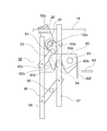
- FIG. 3 is an enlarged front view showing a main part of the car door device when the first and second car doors 2 and 3 in FIG. 1 are fully closed.
- the first car door 2 is provided with a lever shaft 51 and a lever 52.
- the lever shaft 51 is fixed to the first car door 2 parallel to the depth direction of the car and horizontally.
- the lever 52 can rotate around the lever shaft 51. Moreover, the lever 52 has the transmission body connection part 52a.
- the transmitter connection portion 52 a is located at the upper end portion of the lever 52.
- the transmission body connection part 52 a is connected to the transmission body 18 via the gripping member 20. Further, the transmitter connection portion 52 a is rotatable with respect to the gripping member 20 about an axis parallel to the lever shaft 51.
- lever 52 causes the landing door roller 45 to be sandwiched by the vane mechanism 19 when the first car door 2 is opened and closed. Further, the lever 52 releases the pinching of the landing door roller 45 by the vane mechanism 19 when the first car door 2 is fully closed.
- the lever 52 is provided with a lever connecting body 54.
- the lever coupling body 54 is provided on the lever 52 on the opposite side of the lever shaft 51 from the transmission body connecting portion 52a.
- the lever connector 54 is provided at the lower end of the lever shaft 51.
- a roller that can rotate around an axis parallel to the lever shaft 51 is used.
- the distance from the lever shaft 51 to the transmission body connecting portion 52a is larger than the distance from the lever shaft 51 to the lever coupling body 54.
- the vane mechanism 19 includes an upper vane connecting member 53, a connecting member shaft 55, a lower vane connecting member 56, a first vane 57, and a second vane 58.
- the first and second vanes 57 and 58 are arranged in parallel and perpendicular to each other, and sandwich the landing door roller 45 when the first and second car doors 2 are opened and closed.
- the upper vane connecting member 53 is rotatably connected to the first and second vanes 57 and 58.
- the upper vane connecting member 53 is provided on the first car door 2 so as to be rotatable about the lever shaft 51.
- the upper vane connecting member 53 is provided with a slide hole 53a.
- the lever 52 is provided with a protrusion 52b.
- the protrusion 52b has an axial direction parallel to the lever shaft 51 and is inserted into the slide hole 53a. Thereby, the relative rotation of the upper vane connecting member 53 with respect to the lever 52 is restricted.
- the protrusion 52b is slidable within the set range within the slide hole 53a. In other words, a certain margin is provided between the lever 52 and the upper vane connecting member 53.
- the connecting member shaft 55 is fixed to the first car door 2 just below the lever shaft 51. Further, the connecting member shaft 55 is parallel to the lever shaft 51.
- the lower vane connecting member 56 is rotatably connected to the first and second vanes 57 and 58. The lower vane connecting member 56 is provided on the first car door 2 so as to be rotatable about the connecting member shaft 55.
- the upper vane connecting member 53 and the lower vane connecting member 56 function as parallel links that connect the first vane 57 and the second vane 58. Further, the upper vane connecting member 53 interlocks the first and second vanes 57 and 58 with the lever 52.
- FIG. 4 is a front view showing the vane mechanism 19 of FIG.
- FIG. 5 is a front view showing the lever 52 and the gripping member 20 of FIG.
- the first car door 2 is provided with a hook shaft 61 and a hook body 62.
- the hook shaft 61 is fixed to the first car door 2 on the side opposite to the door pocket with respect to the lever shaft 51.
- the hook shaft 61 is parallel to the lever shaft 51.
- the hook body 62 can rotate around the hook shaft 61.
- the hook body 62 transmits the movement of the lever 52 to the first car door 2.
- FIG. 6 is a front view showing the hook body 62 of FIG.
- the hook body 62 has a recess 62a, a claw portion 62b, a hook outer surface 62c, a first inner surface 62d, a second inner surface 62e, and a stopper portion 62f.
- the recess 62a is open downward on the door pocket side of the hook shaft 61.
- the lever coupling body 54 is inserted into the recess 62a.
- the hook body 62 transmits the driving force of the door motor 15 to the first car door 2 as a force in the opening / closing direction.
- claw part 62b is adjacent to the opposite side to the hook shaft 61 of the recessed part 62a.
- the hook outer surface 62c is a surface on the opposite side to the recess 62a of the claw portion 62b, that is, a surface on the door pocket side.
- the first inner surface 62d is the surface of the claw portion 62b opposite to the hook outer surface 62c, that is, the surface from the tip of the claw portion 62b to the bottom of the recess 62a.
- the second inner surface 62e is a surface facing the first inner surface 62d of the recess 62a.
- a release member 63 is fixed to the car door girder 13. When the first and second car doors 2 and 3 are fully closed, the stopper portion 62 f faces the release member 63.
- the circulation direction of the transmission body 18 at this time is a direction in which the gripping member 20 moves to the door pocket side.
- the rotation of the upper vane connecting member 53 causes the first vane 57 to move obliquely upward to the left in FIG. Further, the second vane 58 moves obliquely downward to the right in FIG. As a result, as shown in FIG. 7, the distance between the first and second vanes 57 and 58 is narrowed, and the landing door roller 45 is sandwiched between the first and second vanes 57 and 58.
- the lever coupling body 54 passes through the tip of the claw portion 62b while slightly rotating the hook body 62 in the clockwise direction in FIG. To the second inner surface 62e.
- the second landing door 33 also starts to move toward the door pocket side.
- the gripping member 20 moves to the side opposite to the door pocket.
- the force by which the gripping member 20 moves to the side opposite to the door pocket acts to press the lever coupling body 54 against the first inner surface 62d, and the lever 52 and the hook body 62 are stably coupled to each other.
- the door 2 moves to the opposite side of the door pocket.
- the gripping member 20 After the first and second car doors 2 and 3 are fully closed, the gripping member 20 further moves to the side opposite to the door pocket. Then, the lever 52 rotates in the direction opposite to that at the start of the opening operation, that is, in the clockwise direction in FIG. Thereby, the lever coupling body 54 moves to the hook outer surface 62c side.
- the lever coupling body 54 rotates the hook body 62 in the clockwise direction of FIG. 7 when passing through the tip of the claw portion 62b. Thereby, as shown in FIG. 3, the stopper portion 62 f returns to a state of being separated from the release member 63.
- the vane mechanism 19 is operated by the rotation of the lever 52. Further, the lever coupling body 54 is inserted into the recess 62a when the first and second car doors 2 and 3 are opened and closed. As a result, the driving force of the door motor 15 is stably transmitted to the first car door 2 via the lever 52, the lever coupling body 54, and the hook body 62.
- the vane mechanism 19 can be smoothly operated while shifting the operation timing of the first and second car doors 2 and 3 and the operation timing of the vane mechanism 19.
- the first and second car doors 2 and 3 can also be operated smoothly.
- the stopper 62f is separated from the release member 63 by the rotation of the lever 52 in the direction opposite to that at the start of the opening operation. For this reason, when only the vane mechanism 19 operates, the vane mechanism 19 can be operated more smoothly without being affected by the release member 63. Moreover, the space
- the upper vane connecting member 53 is rotatable with the lever 52 around the lever shaft 51. For this reason, the vane mechanism 19 can be operated more smoothly in conjunction with the rotation of the lever 52.
- vane mechanism 19 can be operated more smoothly by the protrusion 52b sliding in the slide hole 53a.
- the transmission body connecting portion 52a is connected to the transmission body 18 via the gripping member 20. And the transmission body connection part 52a is rotatable with respect to the holding member 20. For this reason, the transmission body 18 can be operated smoothly regardless of the position of the vane mechanism 19.
- the distance from the lever shaft 51 to the transmission body connecting portion 52a is larger than the distance from the lever shaft 51 to the lever coupling body 54. For this reason, the load of the door motor 15 when only the vane mechanism 19 operates can be reduced. Accordingly, it is easy to monitor the motor torque to generate a loss due to a device abnormality occurring in the driving force transmission mechanism and the vane mechanism 19 and contact between the first and second vanes 57 and 58 and the landing door roller 45. Can be detected.
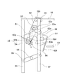
- FIG. 9 is a front view showing an elevator car door device according to Embodiment 2 of the present invention.
- a spring member 64 is provided between the first car door 2 and the hook body 62.
- the spring member 64 applies a mechanical external force to the hook body 62.
- the direction of the mechanical external force is the direction in which the hook outer surface 62c is pressed against the lever connector 54, that is, the counterclockwise direction in FIG.
- the vane mechanism 19 applies a force in a direction to release the pinching of the landing door roller 45 via the hook body 62, the lever coupling body 54, and the lever 52 to the spring member. Receive from 64.
- the spring member 64 for example, a torsion spring provided between the hook shaft 61 and the hook body 62 can be used.
- the spring member 64 may be a coil spring provided between the first car door 2 and the hook body 62.
- Other configurations and operations are the same as those in the first embodiment.
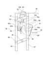
- FIG. 10 is a front view showing an elevator car door device according to Embodiment 3 of the present invention.
- the lever shaft 51 is disposed near the transmitter connection portion 52a. For this reason, the distance from the lever shaft 51 to the lever coupling body 54 is larger than the distance from the lever shaft 51 to the transmission body connecting portion 52a.
- the protrusion 52b is disposed above the lever shaft 51.
- the protrusion 52b is disposed below the lever shaft 51.
- Other configurations and operations are the same as those in the second embodiment.
- the distance from the lever shaft 51 to the lever coupling body 54 is larger than the distance from the lever shaft 51 to the transmission body connecting portion 52a. That is, the distance from the lever shaft 51 to the transmission body connecting portion 52 a is smaller than the distance from the lever shaft 51 to the lever coupling body 54.
- spring member 64 of the third embodiment may be omitted.
- the protrusion 52b is provided on the lever 52 and the slide hole 53a is provided on the upper vane connecting member 53.
- the reverse may be possible.
- the present invention can be applied to a central opening type car door device.
- the number of car doors may be one or three or more.
Landscapes
- Elevator Door Apparatuses (AREA)
Priority Applications (3)
| Application Number | Priority Date | Filing Date | Title |
|---|---|---|---|
| PCT/JP2018/017444 WO2019211900A1 (ja) | 2018-05-01 | 2018-05-01 | エレベータのかごドア装置 |
| CN201880092723.5A CN112020473B (zh) | 2018-05-01 | 2018-05-01 | 电梯的轿厢门装置 |
| JP2020516993A JP6880317B2 (ja) | 2018-05-01 | 2018-05-01 | エレベータのかごドア装置 |
Applications Claiming Priority (1)
| Application Number | Priority Date | Filing Date | Title |
|---|---|---|---|
| PCT/JP2018/017444 WO2019211900A1 (ja) | 2018-05-01 | 2018-05-01 | エレベータのかごドア装置 |
Publications (1)
| Publication Number | Publication Date |
|---|---|
| WO2019211900A1 true WO2019211900A1 (ja) | 2019-11-07 |
Family
ID=68386390
Family Applications (1)
| Application Number | Title | Priority Date | Filing Date |
|---|---|---|---|
| PCT/JP2018/017444 WO2019211900A1 (ja) | 2018-05-01 | 2018-05-01 | エレベータのかごドア装置 |
Country Status (3)
| Country | Link |
|---|---|
| JP (1) | JP6880317B2 (zh) |
| CN (1) | CN112020473B (zh) |
| WO (1) | WO2019211900A1 (zh) |
Cited By (1)
| Publication number | Priority date | Publication date | Assignee | Title |
|---|---|---|---|---|
| WO2023195124A1 (ja) * | 2022-04-07 | 2023-10-12 | 株式会社日立製作所 | エレベーターのドア装置、及び、エレベーター |
Citations (4)
| Publication number | Priority date | Publication date | Assignee | Title |
|---|---|---|---|---|
| JP2005170681A (ja) * | 2003-12-08 | 2005-06-30 | Inventio Ag | エレベータドア駆動装置 |
| US20060225966A1 (en) * | 2003-09-17 | 2006-10-12 | Inventio Ag | Device for Connecting a Car Door with a Shaft Door and for Locking and Unlocking the Doors, a Device for Emergency Unlocking of a Car Door and a Method for Emergency Unlocking of a Car Door |
| WO2009011044A1 (ja) * | 2007-07-18 | 2009-01-22 | Mitsubishi Electric Corporation | エレベータのドア係合装置 |
| WO2011043378A1 (ja) * | 2009-10-09 | 2011-04-14 | 三菱電機株式会社 | エレベータのドア係合装置 |
Family Cites Families (2)
| Publication number | Priority date | Publication date | Assignee | Title |
|---|---|---|---|---|
| KR101153123B1 (ko) * | 2008-06-16 | 2012-06-04 | 미쓰비시덴키 가부시키가이샤 | 엘리베이터의 엘리베이터칸 도어로크장치 |
| WO2016038712A1 (ja) * | 2014-09-11 | 2016-03-17 | 株式会社日立製作所 | エレベータのかごドアロック装置並びにエレベータのドア装置 |
-
2018
- 2018-05-01 JP JP2020516993A patent/JP6880317B2/ja active Active
- 2018-05-01 CN CN201880092723.5A patent/CN112020473B/zh active Active
- 2018-05-01 WO PCT/JP2018/017444 patent/WO2019211900A1/ja active Application Filing
Patent Citations (4)
| Publication number | Priority date | Publication date | Assignee | Title |
|---|---|---|---|---|
| US20060225966A1 (en) * | 2003-09-17 | 2006-10-12 | Inventio Ag | Device for Connecting a Car Door with a Shaft Door and for Locking and Unlocking the Doors, a Device for Emergency Unlocking of a Car Door and a Method for Emergency Unlocking of a Car Door |
| JP2005170681A (ja) * | 2003-12-08 | 2005-06-30 | Inventio Ag | エレベータドア駆動装置 |
| WO2009011044A1 (ja) * | 2007-07-18 | 2009-01-22 | Mitsubishi Electric Corporation | エレベータのドア係合装置 |
| WO2011043378A1 (ja) * | 2009-10-09 | 2011-04-14 | 三菱電機株式会社 | エレベータのドア係合装置 |
Cited By (1)
| Publication number | Priority date | Publication date | Assignee | Title |
|---|---|---|---|---|
| WO2023195124A1 (ja) * | 2022-04-07 | 2023-10-12 | 株式会社日立製作所 | エレベーターのドア装置、及び、エレベーター |
Also Published As
| Publication number | Publication date |
|---|---|
| JP6880317B2 (ja) | 2021-06-02 |
| CN112020473A (zh) | 2020-12-01 |
| JPWO2019211900A1 (ja) | 2020-12-10 |
| CN112020473B (zh) | 2022-07-05 |
Similar Documents
| Publication | Publication Date | Title |
|---|---|---|
| JP5047281B2 (ja) | エレベータのドア装置 | |
| JP5940220B2 (ja) | エレベータのかごドアロック装置 | |
| JP6919841B2 (ja) | ドア用係合装置 | |
| JP2009113976A (ja) | エレベータのドア装置 | |
| JPWO2006097997A1 (ja) | エレベータのかご扉のインターロック装置 | |
| RU2107653C1 (ru) | Устройство соединения кабинной и шахтной дверей лифта | |
| JP3895383B2 (ja) | 自動エレベータドア開閉装置およびドアカプラ | |
| KR20100004987A (ko) | 엘리베이터의 출입구장치 | |
| WO2018138896A1 (ja) | エレベーター装置 | |
| WO2019211900A1 (ja) | エレベータのかごドア装置 | |
| US5636715A (en) | Elevator door structure and method of adjusting the same | |
| JP5832803B2 (ja) | エレベータのホールドア装置 | |
| JP6746042B2 (ja) | エレベータのかごドア装置 | |
| KR100863514B1 (ko) | 엘리베이터 도어 개폐 장치 | |
| JP6440920B1 (ja) | エレベータのかごドア装置 | |
| JP4839593B2 (ja) | エレベータのドア装置 | |
| CN112390117A (zh) | 电梯的门装置 | |
| WO2024042565A1 (ja) | エレベーターの乗場ドア装置 | |
| JP6862605B2 (ja) | エレベータードアの係合装置およびエレベータードア装置 | |
| JP2010285240A (ja) | エレベータ用ドア装置 | |
| JP2009269679A (ja) | エレベータのドア装置 | |
| JPH02270793A (ja) | エレベータドア装置 | |
| CN112390118A (zh) | 电梯的门装置 | |
| JPS5847791A (ja) | エレベ−タの扉開閉装置 | |
| JP2007112544A (ja) | エレベータの戸係合装置 |
Legal Events
| Date | Code | Title | Description |
|---|---|---|---|
| 121 | Ep: the epo has been informed by wipo that ep was designated in this application |
Ref document number: 18917180 Country of ref document: EP Kind code of ref document: A1 |
|
| ENP | Entry into the national phase |
Ref document number: 2020516993 Country of ref document: JP Kind code of ref document: A |
|
| NENP | Non-entry into the national phase |
Ref country code: DE |
|
| 122 | Ep: pct application non-entry in european phase |
Ref document number: 18917180 Country of ref document: EP Kind code of ref document: A1 |