WO2019208570A1 - セラミックス物品の製造方法及びセラミックス物品 - Google Patents
セラミックス物品の製造方法及びセラミックス物品 Download PDFInfo
- Publication number
- WO2019208570A1 WO2019208570A1 PCT/JP2019/017244 JP2019017244W WO2019208570A1 WO 2019208570 A1 WO2019208570 A1 WO 2019208570A1 JP 2019017244 W JP2019017244 W JP 2019017244W WO 2019208570 A1 WO2019208570 A1 WO 2019208570A1
- Authority
- WO
- WIPO (PCT)
- Prior art keywords
- phase
- powder
- containing liquid
- ceramic article
- article according
- Prior art date
- Legal status (The legal status is an assumption and is not a legal conclusion. Google has not performed a legal analysis and makes no representation as to the accuracy of the status listed.)
- Ceased
Links
Images


Classifications
-
- B—PERFORMING OPERATIONS; TRANSPORTING
- B28—WORKING CEMENT, CLAY, OR STONE
- B28B—SHAPING CLAY OR OTHER CERAMIC COMPOSITIONS; SHAPING SLAG; SHAPING MIXTURES CONTAINING CEMENTITIOUS MATERIAL, e.g. PLASTER
- B28B1/00—Producing shaped prefabricated articles from the material
- B28B1/001—Rapid manufacturing of 3D objects by additive depositing, agglomerating or laminating of material
-
- B—PERFORMING OPERATIONS; TRANSPORTING
- B28—WORKING CEMENT, CLAY, OR STONE
- B28B—SHAPING CLAY OR OTHER CERAMIC COMPOSITIONS; SHAPING SLAG; SHAPING MIXTURES CONTAINING CEMENTITIOUS MATERIAL, e.g. PLASTER
- B28B11/00—Apparatus or processes for treating or working the shaped or preshaped articles
- B28B11/04—Apparatus or processes for treating or working the shaped or preshaped articles for coating or applying engobing layers
- B28B11/048—Apparatus or processes for treating or working the shaped or preshaped articles for coating or applying engobing layers by spraying or projecting
-
- B—PERFORMING OPERATIONS; TRANSPORTING
- B32—LAYERED PRODUCTS
- B32B—LAYERED PRODUCTS, i.e. PRODUCTS BUILT-UP OF STRATA OF FLAT OR NON-FLAT, e.g. CELLULAR OR HONEYCOMB, FORM
- B32B18/00—Layered products essentially comprising ceramics, e.g. refractory products
-
- B—PERFORMING OPERATIONS; TRANSPORTING
- B33—ADDITIVE MANUFACTURING TECHNOLOGY
- B33Y—ADDITIVE MANUFACTURING, i.e. MANUFACTURING OF THREE-DIMENSIONAL [3-D] OBJECTS BY ADDITIVE DEPOSITION, ADDITIVE AGGLOMERATION OR ADDITIVE LAYERING, e.g. BY 3-D PRINTING, STEREOLITHOGRAPHY OR SELECTIVE LASER SINTERING
- B33Y10/00—Processes of additive manufacturing
-
- B—PERFORMING OPERATIONS; TRANSPORTING
- B33—ADDITIVE MANUFACTURING TECHNOLOGY
- B33Y—ADDITIVE MANUFACTURING, i.e. MANUFACTURING OF THREE-DIMENSIONAL [3-D] OBJECTS BY ADDITIVE DEPOSITION, ADDITIVE AGGLOMERATION OR ADDITIVE LAYERING, e.g. BY 3-D PRINTING, STEREOLITHOGRAPHY OR SELECTIVE LASER SINTERING
- B33Y30/00—Apparatus for additive manufacturing; Details thereof or accessories therefor
-
- B—PERFORMING OPERATIONS; TRANSPORTING
- B33—ADDITIVE MANUFACTURING TECHNOLOGY
- B33Y—ADDITIVE MANUFACTURING, i.e. MANUFACTURING OF THREE-DIMENSIONAL [3-D] OBJECTS BY ADDITIVE DEPOSITION, ADDITIVE AGGLOMERATION OR ADDITIVE LAYERING, e.g. BY 3-D PRINTING, STEREOLITHOGRAPHY OR SELECTIVE LASER SINTERING
- B33Y40/00—Auxiliary operations or equipment, e.g. for material handling
- B33Y40/20—Post-treatment, e.g. curing, coating or polishing
-
- B—PERFORMING OPERATIONS; TRANSPORTING
- B33—ADDITIVE MANUFACTURING TECHNOLOGY
- B33Y—ADDITIVE MANUFACTURING, i.e. MANUFACTURING OF THREE-DIMENSIONAL [3-D] OBJECTS BY ADDITIVE DEPOSITION, ADDITIVE AGGLOMERATION OR ADDITIVE LAYERING, e.g. BY 3-D PRINTING, STEREOLITHOGRAPHY OR SELECTIVE LASER SINTERING
- B33Y70/00—Materials specially adapted for additive manufacturing
-
- B—PERFORMING OPERATIONS; TRANSPORTING
- B33—ADDITIVE MANUFACTURING TECHNOLOGY
- B33Y—ADDITIVE MANUFACTURING, i.e. MANUFACTURING OF THREE-DIMENSIONAL [3-D] OBJECTS BY ADDITIVE DEPOSITION, ADDITIVE AGGLOMERATION OR ADDITIVE LAYERING, e.g. BY 3-D PRINTING, STEREOLITHOGRAPHY OR SELECTIVE LASER SINTERING
- B33Y80/00—Products made by additive manufacturing
-
- C—CHEMISTRY; METALLURGY
- C04—CEMENTS; CONCRETE; ARTIFICIAL STONE; CERAMICS; REFRACTORIES
- C04B—LIME, MAGNESIA; SLAG; CEMENTS; COMPOSITIONS THEREOF, e.g. MORTARS, CONCRETE OR LIKE BUILDING MATERIALS; ARTIFICIAL STONE; CERAMICS; REFRACTORIES; TREATMENT OF NATURAL STONE
- C04B35/00—Shaped ceramic products characterised by their composition; Ceramics compositions; Processing powders of inorganic compounds preparatory to the manufacturing of ceramic products
- C04B35/01—Shaped ceramic products characterised by their composition; Ceramics compositions; Processing powders of inorganic compounds preparatory to the manufacturing of ceramic products based on oxide ceramics
- C04B35/10—Shaped ceramic products characterised by their composition; Ceramics compositions; Processing powders of inorganic compounds preparatory to the manufacturing of ceramic products based on oxide ceramics based on aluminium oxide
- C04B35/111—Fine ceramics
- C04B35/117—Composites
- C04B35/119—Composites with zirconium oxide
-
- C—CHEMISTRY; METALLURGY
- C04—CEMENTS; CONCRETE; ARTIFICIAL STONE; CERAMICS; REFRACTORIES
- C04B—LIME, MAGNESIA; SLAG; CEMENTS; COMPOSITIONS THEREOF, e.g. MORTARS, CONCRETE OR LIKE BUILDING MATERIALS; ARTIFICIAL STONE; CERAMICS; REFRACTORIES; TREATMENT OF NATURAL STONE
- C04B35/00—Shaped ceramic products characterised by their composition; Ceramics compositions; Processing powders of inorganic compounds preparatory to the manufacturing of ceramic products
- C04B35/01—Shaped ceramic products characterised by their composition; Ceramics compositions; Processing powders of inorganic compounds preparatory to the manufacturing of ceramic products based on oxide ceramics
- C04B35/14—Shaped ceramic products characterised by their composition; Ceramics compositions; Processing powders of inorganic compounds preparatory to the manufacturing of ceramic products based on oxide ceramics based on silica
-
- C—CHEMISTRY; METALLURGY
- C04—CEMENTS; CONCRETE; ARTIFICIAL STONE; CERAMICS; REFRACTORIES
- C04B—LIME, MAGNESIA; SLAG; CEMENTS; COMPOSITIONS THEREOF, e.g. MORTARS, CONCRETE OR LIKE BUILDING MATERIALS; ARTIFICIAL STONE; CERAMICS; REFRACTORIES; TREATMENT OF NATURAL STONE
- C04B35/00—Shaped ceramic products characterised by their composition; Ceramics compositions; Processing powders of inorganic compounds preparatory to the manufacturing of ceramic products
- C04B35/01—Shaped ceramic products characterised by their composition; Ceramics compositions; Processing powders of inorganic compounds preparatory to the manufacturing of ceramic products based on oxide ceramics
- C04B35/44—Shaped ceramic products characterised by their composition; Ceramics compositions; Processing powders of inorganic compounds preparatory to the manufacturing of ceramic products based on oxide ceramics based on aluminates
-
- C—CHEMISTRY; METALLURGY
- C04—CEMENTS; CONCRETE; ARTIFICIAL STONE; CERAMICS; REFRACTORIES
- C04B—LIME, MAGNESIA; SLAG; CEMENTS; COMPOSITIONS THEREOF, e.g. MORTARS, CONCRETE OR LIKE BUILDING MATERIALS; ARTIFICIAL STONE; CERAMICS; REFRACTORIES; TREATMENT OF NATURAL STONE
- C04B35/00—Shaped ceramic products characterised by their composition; Ceramics compositions; Processing powders of inorganic compounds preparatory to the manufacturing of ceramic products
- C04B35/622—Forming processes; Processing powders of inorganic compounds preparatory to the manufacturing of ceramic products
- C04B35/626—Preparing or treating the powders individually or as batches ; preparing or treating macroscopic reinforcing agents for ceramic products, e.g. fibres; mechanical aspects section B
- C04B35/628—Coating the powders or the macroscopic reinforcing agents
- C04B35/62886—Coating the powders or the macroscopic reinforcing agents by wet chemical techniques
-
- C—CHEMISTRY; METALLURGY
- C04—CEMENTS; CONCRETE; ARTIFICIAL STONE; CERAMICS; REFRACTORIES
- C04B—LIME, MAGNESIA; SLAG; CEMENTS; COMPOSITIONS THEREOF, e.g. MORTARS, CONCRETE OR LIKE BUILDING MATERIALS; ARTIFICIAL STONE; CERAMICS; REFRACTORIES; TREATMENT OF NATURAL STONE
- C04B35/00—Shaped ceramic products characterised by their composition; Ceramics compositions; Processing powders of inorganic compounds preparatory to the manufacturing of ceramic products
- C04B35/622—Forming processes; Processing powders of inorganic compounds preparatory to the manufacturing of ceramic products
- C04B35/626—Preparing or treating the powders individually or as batches ; preparing or treating macroscopic reinforcing agents for ceramic products, e.g. fibres; mechanical aspects section B
- C04B35/63—Preparing or treating the powders individually or as batches ; preparing or treating macroscopic reinforcing agents for ceramic products, e.g. fibres; mechanical aspects section B using additives specially adapted for forming the products, e.g.. binder binders
- C04B35/632—Organic additives
-
- C—CHEMISTRY; METALLURGY
- C04—CEMENTS; CONCRETE; ARTIFICIAL STONE; CERAMICS; REFRACTORIES
- C04B—LIME, MAGNESIA; SLAG; CEMENTS; COMPOSITIONS THEREOF, e.g. MORTARS, CONCRETE OR LIKE BUILDING MATERIALS; ARTIFICIAL STONE; CERAMICS; REFRACTORIES; TREATMENT OF NATURAL STONE
- C04B35/00—Shaped ceramic products characterised by their composition; Ceramics compositions; Processing powders of inorganic compounds preparatory to the manufacturing of ceramic products
- C04B35/622—Forming processes; Processing powders of inorganic compounds preparatory to the manufacturing of ceramic products
- C04B35/64—Burning or sintering processes
-
- C—CHEMISTRY; METALLURGY
- C04—CEMENTS; CONCRETE; ARTIFICIAL STONE; CERAMICS; REFRACTORIES
- C04B—LIME, MAGNESIA; SLAG; CEMENTS; COMPOSITIONS THEREOF, e.g. MORTARS, CONCRETE OR LIKE BUILDING MATERIALS; ARTIFICIAL STONE; CERAMICS; REFRACTORIES; TREATMENT OF NATURAL STONE
- C04B35/00—Shaped ceramic products characterised by their composition; Ceramics compositions; Processing powders of inorganic compounds preparatory to the manufacturing of ceramic products
- C04B35/622—Forming processes; Processing powders of inorganic compounds preparatory to the manufacturing of ceramic products
- C04B35/653—Processes involving a melting step
-
- C—CHEMISTRY; METALLURGY
- C04—CEMENTS; CONCRETE; ARTIFICIAL STONE; CERAMICS; REFRACTORIES
- C04B—LIME, MAGNESIA; SLAG; CEMENTS; COMPOSITIONS THEREOF, e.g. MORTARS, CONCRETE OR LIKE BUILDING MATERIALS; ARTIFICIAL STONE; CERAMICS; REFRACTORIES; TREATMENT OF NATURAL STONE
- C04B41/00—After-treatment of mortars, concrete, artificial stone or ceramics; Treatment of natural stone
- C04B41/009—After-treatment of mortars, concrete, artificial stone or ceramics; Treatment of natural stone characterised by the material treated
-
- C—CHEMISTRY; METALLURGY
- C04—CEMENTS; CONCRETE; ARTIFICIAL STONE; CERAMICS; REFRACTORIES
- C04B—LIME, MAGNESIA; SLAG; CEMENTS; COMPOSITIONS THEREOF, e.g. MORTARS, CONCRETE OR LIKE BUILDING MATERIALS; ARTIFICIAL STONE; CERAMICS; REFRACTORIES; TREATMENT OF NATURAL STONE
- C04B41/00—After-treatment of mortars, concrete, artificial stone or ceramics; Treatment of natural stone
- C04B41/45—Coating or impregnating, e.g. injection in masonry, partial coating of green or fired ceramics, organic coating compositions for adhering together two concrete elements
- C04B41/4505—Coating or impregnating, e.g. injection in masonry, partial coating of green or fired ceramics, organic coating compositions for adhering together two concrete elements characterised by the method of application
- C04B41/4535—Coating or impregnating, e.g. injection in masonry, partial coating of green or fired ceramics, organic coating compositions for adhering together two concrete elements characterised by the method of application applied as a solution, emulsion, dispersion or suspension
-
- C—CHEMISTRY; METALLURGY
- C04—CEMENTS; CONCRETE; ARTIFICIAL STONE; CERAMICS; REFRACTORIES
- C04B—LIME, MAGNESIA; SLAG; CEMENTS; COMPOSITIONS THEREOF, e.g. MORTARS, CONCRETE OR LIKE BUILDING MATERIALS; ARTIFICIAL STONE; CERAMICS; REFRACTORIES; TREATMENT OF NATURAL STONE
- C04B41/00—After-treatment of mortars, concrete, artificial stone or ceramics; Treatment of natural stone
- C04B41/80—After-treatment of mortars, concrete, artificial stone or ceramics; Treatment of natural stone of only ceramics
- C04B41/81—Coating or impregnation
- C04B41/85—Coating or impregnation with inorganic materials
- C04B41/87—Ceramics
-
- C—CHEMISTRY; METALLURGY
- C04—CEMENTS; CONCRETE; ARTIFICIAL STONE; CERAMICS; REFRACTORIES
- C04B—LIME, MAGNESIA; SLAG; CEMENTS; COMPOSITIONS THEREOF, e.g. MORTARS, CONCRETE OR LIKE BUILDING MATERIALS; ARTIFICIAL STONE; CERAMICS; REFRACTORIES; TREATMENT OF NATURAL STONE
- C04B2235/00—Aspects relating to ceramic starting mixtures or sintered ceramic products
- C04B2235/02—Composition of constituents of the starting material or of secondary phases of the final product
- C04B2235/30—Constituents and secondary phases not being of a fibrous nature
- C04B2235/32—Metal oxides, mixed metal oxides, or oxide-forming salts thereof, e.g. carbonates, nitrates, (oxy)hydroxides, chlorides
- C04B2235/3217—Aluminum oxide or oxide forming salts thereof, e.g. bauxite, alpha-alumina
- C04B2235/3222—Aluminates other than alumino-silicates, e.g. spinel (MgAl2O4)
-
- C—CHEMISTRY; METALLURGY
- C04—CEMENTS; CONCRETE; ARTIFICIAL STONE; CERAMICS; REFRACTORIES
- C04B—LIME, MAGNESIA; SLAG; CEMENTS; COMPOSITIONS THEREOF, e.g. MORTARS, CONCRETE OR LIKE BUILDING MATERIALS; ARTIFICIAL STONE; CERAMICS; REFRACTORIES; TREATMENT OF NATURAL STONE
- C04B2235/00—Aspects relating to ceramic starting mixtures or sintered ceramic products
- C04B2235/02—Composition of constituents of the starting material or of secondary phases of the final product
- C04B2235/30—Constituents and secondary phases not being of a fibrous nature
- C04B2235/32—Metal oxides, mixed metal oxides, or oxide-forming salts thereof, e.g. carbonates, nitrates, (oxy)hydroxides, chlorides
- C04B2235/3224—Rare earth oxide or oxide forming salts thereof, e.g. scandium oxide
-
- C—CHEMISTRY; METALLURGY
- C04—CEMENTS; CONCRETE; ARTIFICIAL STONE; CERAMICS; REFRACTORIES
- C04B—LIME, MAGNESIA; SLAG; CEMENTS; COMPOSITIONS THEREOF, e.g. MORTARS, CONCRETE OR LIKE BUILDING MATERIALS; ARTIFICIAL STONE; CERAMICS; REFRACTORIES; TREATMENT OF NATURAL STONE
- C04B2235/00—Aspects relating to ceramic starting mixtures or sintered ceramic products
- C04B2235/02—Composition of constituents of the starting material or of secondary phases of the final product
- C04B2235/30—Constituents and secondary phases not being of a fibrous nature
- C04B2235/32—Metal oxides, mixed metal oxides, or oxide-forming salts thereof, e.g. carbonates, nitrates, (oxy)hydroxides, chlorides
- C04B2235/3231—Refractory metal oxides, their mixed metal oxides, or oxide-forming salts thereof
- C04B2235/3244—Zirconium oxides, zirconates, hafnium oxides, hafnates, or oxide-forming salts thereof
-
- C—CHEMISTRY; METALLURGY
- C04—CEMENTS; CONCRETE; ARTIFICIAL STONE; CERAMICS; REFRACTORIES
- C04B—LIME, MAGNESIA; SLAG; CEMENTS; COMPOSITIONS THEREOF, e.g. MORTARS, CONCRETE OR LIKE BUILDING MATERIALS; ARTIFICIAL STONE; CERAMICS; REFRACTORIES; TREATMENT OF NATURAL STONE
- C04B2235/00—Aspects relating to ceramic starting mixtures or sintered ceramic products
- C04B2235/02—Composition of constituents of the starting material or of secondary phases of the final product
- C04B2235/30—Constituents and secondary phases not being of a fibrous nature
- C04B2235/34—Non-metal oxides, non-metal mixed oxides, or salts thereof that form the non-metal oxides upon heating, e.g. carbonates, nitrates, (oxy)hydroxides, chlorides
- C04B2235/3418—Silicon oxide, silicic acids or oxide forming salts thereof, e.g. silica sol, fused silica, silica fume, cristobalite, quartz or flint
-
- C—CHEMISTRY; METALLURGY
- C04—CEMENTS; CONCRETE; ARTIFICIAL STONE; CERAMICS; REFRACTORIES
- C04B—LIME, MAGNESIA; SLAG; CEMENTS; COMPOSITIONS THEREOF, e.g. MORTARS, CONCRETE OR LIKE BUILDING MATERIALS; ARTIFICIAL STONE; CERAMICS; REFRACTORIES; TREATMENT OF NATURAL STONE
- C04B2235/00—Aspects relating to ceramic starting mixtures or sintered ceramic products
- C04B2235/02—Composition of constituents of the starting material or of secondary phases of the final product
- C04B2235/30—Constituents and secondary phases not being of a fibrous nature
- C04B2235/44—Metal salt constituents or additives chosen for the nature of the anions, e.g. hydrides or acetylacetonate
- C04B2235/441—Alkoxides, e.g. methoxide, tert-butoxide
-
- C—CHEMISTRY; METALLURGY
- C04—CEMENTS; CONCRETE; ARTIFICIAL STONE; CERAMICS; REFRACTORIES
- C04B—LIME, MAGNESIA; SLAG; CEMENTS; COMPOSITIONS THEREOF, e.g. MORTARS, CONCRETE OR LIKE BUILDING MATERIALS; ARTIFICIAL STONE; CERAMICS; REFRACTORIES; TREATMENT OF NATURAL STONE
- C04B2235/00—Aspects relating to ceramic starting mixtures or sintered ceramic products
- C04B2235/02—Composition of constituents of the starting material or of secondary phases of the final product
- C04B2235/50—Constituents or additives of the starting mixture chosen for their shape or used because of their shape or their physical appearance
- C04B2235/54—Particle size related information
- C04B2235/5418—Particle size related information expressed by the size of the particles or aggregates thereof
- C04B2235/5436—Particle size related information expressed by the size of the particles or aggregates thereof micrometer sized, i.e. from 1 to 100 micron
-
- C—CHEMISTRY; METALLURGY
- C04—CEMENTS; CONCRETE; ARTIFICIAL STONE; CERAMICS; REFRACTORIES
- C04B—LIME, MAGNESIA; SLAG; CEMENTS; COMPOSITIONS THEREOF, e.g. MORTARS, CONCRETE OR LIKE BUILDING MATERIALS; ARTIFICIAL STONE; CERAMICS; REFRACTORIES; TREATMENT OF NATURAL STONE
- C04B2235/00—Aspects relating to ceramic starting mixtures or sintered ceramic products
- C04B2235/60—Aspects relating to the preparation, properties or mechanical treatment of green bodies or pre-forms
- C04B2235/602—Making the green bodies or pre-forms by moulding
- C04B2235/6026—Computer aided shaping, e.g. rapid prototyping
-
- C—CHEMISTRY; METALLURGY
- C04—CEMENTS; CONCRETE; ARTIFICIAL STONE; CERAMICS; REFRACTORIES
- C04B—LIME, MAGNESIA; SLAG; CEMENTS; COMPOSITIONS THEREOF, e.g. MORTARS, CONCRETE OR LIKE BUILDING MATERIALS; ARTIFICIAL STONE; CERAMICS; REFRACTORIES; TREATMENT OF NATURAL STONE
- C04B2235/00—Aspects relating to ceramic starting mixtures or sintered ceramic products
- C04B2235/60—Aspects relating to the preparation, properties or mechanical treatment of green bodies or pre-forms
- C04B2235/616—Liquid infiltration of green bodies or pre-forms
-
- C—CHEMISTRY; METALLURGY
- C04—CEMENTS; CONCRETE; ARTIFICIAL STONE; CERAMICS; REFRACTORIES
- C04B—LIME, MAGNESIA; SLAG; CEMENTS; COMPOSITIONS THEREOF, e.g. MORTARS, CONCRETE OR LIKE BUILDING MATERIALS; ARTIFICIAL STONE; CERAMICS; REFRACTORIES; TREATMENT OF NATURAL STONE
- C04B2235/00—Aspects relating to ceramic starting mixtures or sintered ceramic products
- C04B2235/65—Aspects relating to heat treatments of ceramic bodies such as green ceramics or pre-sintered ceramics, e.g. burning, sintering or melting processes
- C04B2235/656—Aspects relating to heat treatments of ceramic bodies such as green ceramics or pre-sintered ceramics, e.g. burning, sintering or melting processes characterised by specific heating conditions during heat treatment
- C04B2235/6562—Heating rate
-
- C—CHEMISTRY; METALLURGY
- C04—CEMENTS; CONCRETE; ARTIFICIAL STONE; CERAMICS; REFRACTORIES
- C04B—LIME, MAGNESIA; SLAG; CEMENTS; COMPOSITIONS THEREOF, e.g. MORTARS, CONCRETE OR LIKE BUILDING MATERIALS; ARTIFICIAL STONE; CERAMICS; REFRACTORIES; TREATMENT OF NATURAL STONE
- C04B2235/00—Aspects relating to ceramic starting mixtures or sintered ceramic products
- C04B2235/65—Aspects relating to heat treatments of ceramic bodies such as green ceramics or pre-sintered ceramics, e.g. burning, sintering or melting processes
- C04B2235/656—Aspects relating to heat treatments of ceramic bodies such as green ceramics or pre-sintered ceramics, e.g. burning, sintering or melting processes characterised by specific heating conditions during heat treatment
- C04B2235/6565—Cooling rate
-
- C—CHEMISTRY; METALLURGY
- C04—CEMENTS; CONCRETE; ARTIFICIAL STONE; CERAMICS; REFRACTORIES
- C04B—LIME, MAGNESIA; SLAG; CEMENTS; COMPOSITIONS THEREOF, e.g. MORTARS, CONCRETE OR LIKE BUILDING MATERIALS; ARTIFICIAL STONE; CERAMICS; REFRACTORIES; TREATMENT OF NATURAL STONE
- C04B2235/00—Aspects relating to ceramic starting mixtures or sintered ceramic products
- C04B2235/65—Aspects relating to heat treatments of ceramic bodies such as green ceramics or pre-sintered ceramics, e.g. burning, sintering or melting processes
- C04B2235/66—Specific sintering techniques, e.g. centrifugal sintering
- C04B2235/665—Local sintering, e.g. laser sintering
-
- C—CHEMISTRY; METALLURGY
- C04—CEMENTS; CONCRETE; ARTIFICIAL STONE; CERAMICS; REFRACTORIES
- C04B—LIME, MAGNESIA; SLAG; CEMENTS; COMPOSITIONS THEREOF, e.g. MORTARS, CONCRETE OR LIKE BUILDING MATERIALS; ARTIFICIAL STONE; CERAMICS; REFRACTORIES; TREATMENT OF NATURAL STONE
- C04B2235/00—Aspects relating to ceramic starting mixtures or sintered ceramic products
- C04B2235/70—Aspects relating to sintered or melt-casted ceramic products
- C04B2235/74—Physical characteristics
- C04B2235/77—Density
-
- C—CHEMISTRY; METALLURGY
- C04—CEMENTS; CONCRETE; ARTIFICIAL STONE; CERAMICS; REFRACTORIES
- C04B—LIME, MAGNESIA; SLAG; CEMENTS; COMPOSITIONS THEREOF, e.g. MORTARS, CONCRETE OR LIKE BUILDING MATERIALS; ARTIFICIAL STONE; CERAMICS; REFRACTORIES; TREATMENT OF NATURAL STONE
- C04B2235/00—Aspects relating to ceramic starting mixtures or sintered ceramic products
- C04B2235/70—Aspects relating to sintered or melt-casted ceramic products
- C04B2235/74—Physical characteristics
- C04B2235/78—Grain sizes and shapes, product microstructures, e.g. acicular grains, equiaxed grains, platelet-structures
- C04B2235/786—Micrometer sized grains, i.e. from 1 to 100 micron
-
- C—CHEMISTRY; METALLURGY
- C04—CEMENTS; CONCRETE; ARTIFICIAL STONE; CERAMICS; REFRACTORIES
- C04B—LIME, MAGNESIA; SLAG; CEMENTS; COMPOSITIONS THEREOF, e.g. MORTARS, CONCRETE OR LIKE BUILDING MATERIALS; ARTIFICIAL STONE; CERAMICS; REFRACTORIES; TREATMENT OF NATURAL STONE
- C04B2235/00—Aspects relating to ceramic starting mixtures or sintered ceramic products
- C04B2235/70—Aspects relating to sintered or melt-casted ceramic products
- C04B2235/80—Phases present in the sintered or melt-cast ceramic products other than the main phase
-
- C—CHEMISTRY; METALLURGY
- C04—CEMENTS; CONCRETE; ARTIFICIAL STONE; CERAMICS; REFRACTORIES
- C04B—LIME, MAGNESIA; SLAG; CEMENTS; COMPOSITIONS THEREOF, e.g. MORTARS, CONCRETE OR LIKE BUILDING MATERIALS; ARTIFICIAL STONE; CERAMICS; REFRACTORIES; TREATMENT OF NATURAL STONE
- C04B2235/00—Aspects relating to ceramic starting mixtures or sintered ceramic products
- C04B2235/70—Aspects relating to sintered or melt-casted ceramic products
- C04B2235/94—Products characterised by their shape
-
- C—CHEMISTRY; METALLURGY
- C04—CEMENTS; CONCRETE; ARTIFICIAL STONE; CERAMICS; REFRACTORIES
- C04B—LIME, MAGNESIA; SLAG; CEMENTS; COMPOSITIONS THEREOF, e.g. MORTARS, CONCRETE OR LIKE BUILDING MATERIALS; ARTIFICIAL STONE; CERAMICS; REFRACTORIES; TREATMENT OF NATURAL STONE
- C04B2235/00—Aspects relating to ceramic starting mixtures or sintered ceramic products
- C04B2235/70—Aspects relating to sintered or melt-casted ceramic products
- C04B2235/95—Products characterised by their size, e.g. microceramics
-
- C—CHEMISTRY; METALLURGY
- C04—CEMENTS; CONCRETE; ARTIFICIAL STONE; CERAMICS; REFRACTORIES
- C04B—LIME, MAGNESIA; SLAG; CEMENTS; COMPOSITIONS THEREOF, e.g. MORTARS, CONCRETE OR LIKE BUILDING MATERIALS; ARTIFICIAL STONE; CERAMICS; REFRACTORIES; TREATMENT OF NATURAL STONE
- C04B2235/00—Aspects relating to ceramic starting mixtures or sintered ceramic products
- C04B2235/70—Aspects relating to sintered or melt-casted ceramic products
- C04B2235/96—Properties of ceramic products, e.g. mechanical properties such as strength, toughness, wear resistance
- C04B2235/9607—Thermal properties, e.g. thermal expansion coefficient
- C04B2235/9623—Ceramic setters properties
-
- C—CHEMISTRY; METALLURGY
- C04—CEMENTS; CONCRETE; ARTIFICIAL STONE; CERAMICS; REFRACTORIES
- C04B—LIME, MAGNESIA; SLAG; CEMENTS; COMPOSITIONS THEREOF, e.g. MORTARS, CONCRETE OR LIKE BUILDING MATERIALS; ARTIFICIAL STONE; CERAMICS; REFRACTORIES; TREATMENT OF NATURAL STONE
- C04B2237/00—Aspects relating to ceramic laminates or to joining of ceramic articles with other articles by heating
- C04B2237/30—Composition of layers of ceramic laminates or of ceramic or metallic articles to be joined by heating, e.g. Si substrates
- C04B2237/32—Ceramic
- C04B2237/34—Oxidic
- C04B2237/343—Alumina or aluminates
-
- C—CHEMISTRY; METALLURGY
- C04—CEMENTS; CONCRETE; ARTIFICIAL STONE; CERAMICS; REFRACTORIES
- C04B—LIME, MAGNESIA; SLAG; CEMENTS; COMPOSITIONS THEREOF, e.g. MORTARS, CONCRETE OR LIKE BUILDING MATERIALS; ARTIFICIAL STONE; CERAMICS; REFRACTORIES; TREATMENT OF NATURAL STONE
- C04B2237/00—Aspects relating to ceramic laminates or to joining of ceramic articles with other articles by heating
- C04B2237/50—Processing aspects relating to ceramic laminates or to the joining of ceramic articles with other articles by heating
- C04B2237/70—Forming laminates or joined articles comprising layers of a specific, unusual thickness
- C04B2237/704—Forming laminates or joined articles comprising layers of a specific, unusual thickness of one or more of the ceramic layers or articles
-
- Y—GENERAL TAGGING OF NEW TECHNOLOGICAL DEVELOPMENTS; GENERAL TAGGING OF CROSS-SECTIONAL TECHNOLOGIES SPANNING OVER SEVERAL SECTIONS OF THE IPC; TECHNICAL SUBJECTS COVERED BY FORMER USPC CROSS-REFERENCE ART COLLECTIONS [XRACs] AND DIGESTS
- Y02—TECHNOLOGIES OR APPLICATIONS FOR MITIGATION OR ADAPTATION AGAINST CLIMATE CHANGE
- Y02P—CLIMATE CHANGE MITIGATION TECHNOLOGIES IN THE PRODUCTION OR PROCESSING OF GOODS
- Y02P10/00—Technologies related to metal processing
- Y02P10/25—Process efficiency
Definitions
- the present invention relates to a method for manufacturing a ceramic article using additive modeling technology, and a ceramic article manufactured by such a manufacturing method.
- the material powder is irradiated with an energy beam based on the three-dimensional data of the object to be modeled, and the material powder is combined to form the desired model
- Additive modeling technology for obtaining objects is widespread.
- metal powder metal modeling
- a powder bed laser direct modeling method is widely adopted, and a dense and diverse metal model is obtained.
- the high density of the metal shaped article is realized by effectively melting and solidifying the metal powder.
- Non-Patent Document 1 by lowering the melting point using ceramics having an Al 2 O 3 —ZrO 2 eutectic composition, energy required for melting is reduced and thermal stress is alleviated. And the technique which suppresses generation
- Non-Patent Document 1 since the modeled object has a phase separation structure peculiar to a eutectic system, the mechanical strength such as three-point bending strength is excellent, but the ceramic material around the modeled object heated by the heater Since a part of the powder is melted, the modeling accuracy is extremely low.
- the present invention has been made in order to cope with such a problem, and provides a method for manufacturing a ceramic article that achieves an improvement in mechanical strength of a modeled object while achieving high modeling accuracy in a direct modeling method. is there.
- a method for producing a ceramic article according to one aspect of the present invention includes: (I) a step of disposing a powder mainly composed of ceramics on a base; (Ii) a step of irradiating part or all of the arranged powder with an energy beam to melt and solidify the powder to obtain a shaped article; (Iii) The molded object has a step of absorbing the metal component-containing liquid, and (iv) a step of heating the molded object that has absorbed the metal component-containing liquid.
- a ceramic article according to another aspect of the present invention is a ceramic shaped article having a phase separation structure composed of at least three phases of an X phase, a Y phase, and a Z phase, and the materials constituting the three phases are in a eutectic relationship.
- the average particle diameter x of the grains constituting the X phase, the average grain diameter y of the grains constituting the Y phase, and the average grain diameter z of the grains constituting the Z phase are z / x ⁇ 0.5 and It satisfies the relationship of z / y ⁇ 0.5.
- the method for manufacturing a ceramic article according to the present invention includes: (I) a step of disposing a powder mainly composed of ceramics on a base; (Ii) a step of irradiating part or all of the arranged powder with an energy beam to melt and solidify the powder to obtain a shaped article; (Iii) The molded object has a step of absorbing the metal component-containing liquid, and (iv) a step of heating the molded object that has absorbed the metal component-containing liquid.
- the production method of the present invention is suitable for the production of a three-dimensional structure of a direct shaping method, among which a powder bed direct shaping method, a directional energy lamination method (so-called cladding method) that builds up a modeling material, etc.
- a direct shaping method among which a powder bed direct shaping method, a directional energy lamination method (so-called cladding method) that builds up a modeling material, etc.
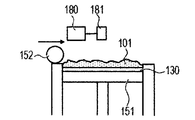
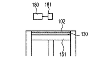
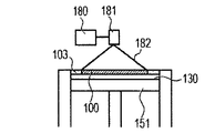
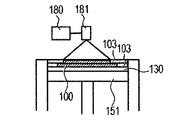
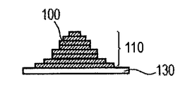
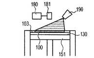
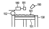
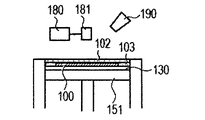
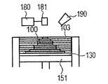
- the powder 101 is mounted on the base 130 installed in the stage 151, and the powder layer 102 is formed using the roller 152 (FIGS. 1A and 1B).
- the powder layer 102 is irradiated with the energy beam emitted from the energy beam source 180 to the irradiation range 182 corresponding to the modeling shape while being scanned by the scanner unit 181, the powder is melted and then solidified to form the modeling object 100. Formed (FIG. 1C).
- the stage 151 is lowered and a powder layer 102 is newly formed on the modeled object 100 (FIG. 1D).
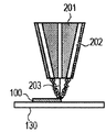
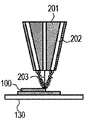
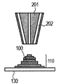
- the cladding method will be described with reference to FIGS. 2A to 2C.
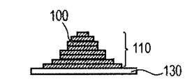
- powder is ejected from a plurality of powder supply holes 202 in the cladding nozzle 201, and an energy beam 203 is irradiated to a region where the powders are focused, and the molded article 100 is additionally added to a desired place. Is formed (FIG. 2A), and this process is repeated to obtain a shaped article 110 having a desired shape (FIGS. 2B and 2C). Finally, removal of unnecessary parts of the modeled object and separation of the modeled object and the base are performed as necessary.
- a direct shaping method such as a powder bed direct shaping method or a cladding method
- the powder melted by energy beam irradiation is cooled and solidified by the surroundings to form a shaped object.
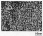
- many microcracks are generated in the molded article. Microcracks are distributed over the entire model (surface and interior). When the cross section of the modeled object is confirmed with a scanning electron microscope or the like, most of the microcracks have a width of several nm to several ⁇ m. The length of the microcrack varies from several ⁇ m to several mm.
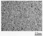
- the liquid containing the metal component is absorbed in the microcracks of the modeled object and heated, so that the vicinity of the microcracks can be selectively melted, and the modeled object is suppressed while suppressing changes in the shape of the modeled object.
- the inside microcracks can be reduced, and the mechanical strength of a molded article can be improved.
- the energy beam applied to the powder layer is preferably controlled so as to have a gentle intensity profile on the surface of the powder layer.
- irradiating the beam having a gentle intensity profile it is possible to reduce the influence on the shaped part that has already been completely melted and solidified, which exists in the lower layer of the irradiated part.
- the generation of the microcracks can be controlled by the drawing direction or the like, and the microcracks can be generated uniformly over the entire intermediate shaped article.
- the metal component-containing liquid to be absorbed by the microcracks is preferably a metal compound, particularly a metal oxide, by heat treatment performed after the metal component-containing liquid is absorbed.
- the change to the metal oxide is preferably caused by the metal component-containing liquid itself to be absorbed alone, but is also preferably accompanied by compounding, solid solution, or diffusion with the material constituting the shaped article.
- the metal oxide formed by the heat treatment is a phase that can be in a eutectic relationship with the phase constituting the shaped article.
- the modeled object is composed of a plurality of phases, it may be a phase that can be in a eutectic relationship with any of the phases composing the modeled object.
- the metal oxide phase formed by the heat treatment and the phase contained in the shaped object are in a eutectic relationship, so that the temperature is lower than the melting point of the shaped object. It melts and the metal component diffuses into the shaped object.
- the crystal is recrystallized in the modeled object with a composition containing a metal component.
- a composition containing a metal component As a result, while maintaining the shape of the modeled object, only the area near the microcracks is softened, and the effect of reducing or eliminating the microcracks is obtained. Furthermore, the bonding force between crystal compositions such as grain boundaries of the modeled object becomes strong, and the wear resistance of the modeled object is improved.
- the grain boundary means a boundary between crystal grains.
- the crystal grains may be simply referred to as “grains”.
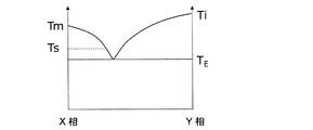
- FIG. 10 shows a relationship between the composition ratio and the state of the X phase and the Y phase when the X phase constituting the modeled object and the metal oxide Y phase formed from the metal component-containing liquid are in a eutectic relationship. The figure is shown.
- the melting point of the X phase is T m
- the melting point of the Y phase is T i
- the eutectic temperature of the X phase and the Y phase is T E
- the respective temperatures have the relationship of T E ⁇ T m and T E ⁇ T i . Fulfill.
- T S the maximum temperature at which the shaped article reaches by heat treatment performed after absorbing the metal component-containing liquid so that T E ⁇ T S ⁇ T m . More preferably, T E ⁇ T S ⁇ T m ⁇ (T m ⁇ T E ) / 2. Accordingly, selectively melt the vicinity of the microcracks at a temperature lower than the melting point T m of a modeled object, since it is possible to reduce or eliminate microcracks, the shape of the shaped article tends to maintain.
- the metal component-containing liquid is preferably a zirconium component-containing liquid, and from the zirconium component-containing liquid, zirconia ( ZrO 2 ; melting point T i : 2715 ° C.) phase is formed.
- the eutectic temperature of Al 2 O 3 and ZrO 2 is about 1900 ° C.. That is, Al 2 O 3 and ZrO 2 are a preferable combination that satisfies the relationship of T m ⁇ T i .
- the concentration of the ZrO 2 component absorbed in the microcracks is adjusted, and the ratio of Al 2 O 3 and ZrO 2 in the vicinity of the microcracks is brought close to the eutectic composition, so that during the heat treatment the maximum temperature T S can be set in the range of 1900 °C ⁇ T S ⁇ 2070 °C of. Therefore, the microcracks can be reduced or eliminated by melting at a temperature sufficiently lower than the melting point of Al 2 O 3 .
- the melting point of the modeled object is determined according to the composition ratio of the two phases. For example, if the two phases have a eutectic composition, the melting point is about 1720 ° C.
- the metal component-containing liquid at this time it is possible to select a zirconium component-containing liquid in which a ZrO 2 phase is generated by heat treatment. Although the melting point of the ZrO 2 phase is 2715 ° C., the eutectic temperature of the three phases of Al 2 O 3 , GdAlO 3, and ZrO 2 is about 1662 ° C. at a maximum temperature T S, it is possible to reduce or eliminate the microcracks.
- the melting point of the modeled object is determined according to the composition ratio of the two phases. For example, if the two phases have a eutectic composition, the melting point is about 1900 ° C.
- the metal component-containing liquid at this time a liquid containing gadolinium and an aluminum component at 1: 1 can be selected. In this case, GdAlO 3 phase is produced by heat treatment, and its melting point is 2050 ° C.
- the heat treatment is performed at a temperature sufficiently lower than about 1900 ° C. which is the melting temperature of the shaped article. It is possible to reduce or eliminate microcracks.
- T m ⁇ T i examples of combinations satisfying the relationship of T m ⁇ T i include SiO 2 and ZrO 2 , SiO 2 and Al 2 O 3 , Al 2 O 3 and MgO, Al 2 O 3 and HfO 2 , [Al 2 O 3 and ReAlO 3 (Re is a rare earth)] and ZrO 2 , [Al 2 O 3 and Re 3 Al 5 O 12 (Re is a rare earth)] and ZrO 2 , [Al 2 O 3 and ReAlO 3 (Re is a rare earth)] And HfO 2 , [Al 2 O 3 and Re 3 Al 5 O 12 (Re is a rare earth)], HfO 2 , Mg 2 Al 4 Si 5 O 18 and Mg 2 SiO 4 , Mg 2 Al 4 Si 5 O 18 and MgSiO 3 and the like, but are not limited
- the shaped object is composed of a crystalline structure or an amorphous structure formed by irradiation with an energy beam.
- the metal component diffuses into the crystalline structure or the amorphous structure and recrystallizes in the heating step after the metal component-containing liquid is absorbed.
- grains (for example, average particle diameter) after a heating differ in the particle
- the modeling object is composed of a phase separation structure composed of a plurality of phases having different average particle diameters of grains, so that the bonding force between crystal structures becomes strong. As a result, the mechanical strength, wear resistance, and machinability of the resulting molded article are improved, and precise finishing with few chips is possible.
- the present invention is characterized in that a metal component is introduced into a shaped article prepared by melting and solidifying a powder with an energy beam, and the metal component that is absorbed into the microcrack later in the powder before melting.
- the same effects as those of the present invention cannot be obtained.
- the metal compound contained in advance in the powder before melting is preferably less than 3 mol%, more preferably less than 2 mol%.
- the metal compound contained in advance is preferably less than 1 mol%.
- the production method of the present invention is characterized by the following four steps.
- a powder mainly composed of ceramics is placed on a base.
- a part or all of the arranged powder is irradiated with an energy beam to melt and solidify the powder to obtain a shaped article.
- the molded object is allowed to absorb the metal component-containing liquid.
- the shaped object that has absorbed the metal component-containing liquid is heated.
- a powder containing aluminum oxide as a main component (hereinafter sometimes referred to as a raw material powder) is placed on a base.
- the most abundant component is called a main component, and “powder mainly composed of aluminum oxide” A powder containing the most aluminum oxide in a molar ratio.
- the powder containing aluminum oxide as a main component preferably contains a rare earth element oxide that produces a eutectic composition with aluminum oxide as a subcomponent. It is particularly preferable that at least one selected from gadolinium oxide, terbium oxide and praseodymium oxide is included.
- the raw material powder contains gadolinium oxide that generates a eutectic composition with aluminum oxide
- the melting point is lower than that of aluminum oxide alone in the vicinity of the Al 2 O 3 —Gd 2 O 3 eutectic composition.
- the powder can be melted with a small amount of heat, and the diffusion of energy in the powder is suppressed, so that the modeling accuracy is improved.
- the shaped product when the raw material powder contains gadolinium oxide, the shaped product has a phase separation structure composed of two or more phases. Thereby, extension of a crack is suppressed and the mechanical strength of a modeled object improves.
- the same effect as in the case of gadolinium oxide can be obtained when oxides of other rare earth elements (excluding terbium and praseodymium) such as yttrium oxide are included instead of gadolinium oxide.
- the powder When the energy beam is a laser beam, the powder has sufficient energy absorption, which suppresses the spread of heat in the powder and becomes localized, reducing the influence of heat on the non-modeling part, so that the modeling accuracy Will improve.
- terbium oxide (Tb 4 O 7 ), praseodymium oxide (Pr 6 O 11 ), and the like exhibit good energy absorption, so that they are contained in the powder as a subsidiary component. More preferably.
- the raw material powder may contain both rare earth elements exhibiting good energy absorption with respect to a laser beam such as terbium oxide (Tb 4 O 7 ) and praseodymium oxide (Pr 6 O 11 ) and other rare earth elements. preferable.
- the raw material powder preferably contains a eutectic composition in a ratio of the eutectic composition.
- the eutectic composition is the composition at the eutectic point shown in the eutectic phase diagram, but the molding process using the energy beam repeats heating and cooling at a very high speed, so the composition deviates from the eutectic point. Even so, a eutectic structure having a phase separation structure is formed. Therefore, the eutectic composition in the present invention is preferably defined as a composition range in which a eutectic structure is formed, and includes a range of ⁇ 10 mol% with respect to the eutectic composition referred to in the eutectic phase diagram. Similarly, in the case of a powder whose main component is other than aluminum oxide, it is also preferable that the composition forming the eutectic is contained in a ratio forming the eutectic composition.
- materials may be expressed using chemical formulas such as Al 2 O 3 and Tb 4 O 7 described above. However, if the gist of the present invention is satisfied, elements of actual materials may be expressed.
- the composition ratio does not have to be exactly the same as the chemical formula ratio. That is, the valence of the metal element constituting a certain material may be slightly different from the valence assumed from the chemical formula.
- the valence of Tb assumed from Tb 4 O 7 is tetravalent, but terbium oxide in a range of 3.5 or more and smaller than 4.5 is included in Tb 4 O 7 .
- the base material used in the present invention is appropriately selected and used from materials such as ceramics, metal, glass and the like generally used in the production of three-dimensional structures in consideration of the use and manufacturing conditions of the objects. be able to.
- a heat-resistant ceramic for the base.
- the method for arranging the powder on the base is not particularly limited.
- the powder bed direct modeling method as shown in FIGS. 1A to 1H
- the powder is arranged in layers on the base with a roller, a blade or the like.
- the cladding method as shown in FIGS. 2A to 2C
- the powder is sprayed and supplied from the nozzle to the irradiation position of the energy beam, and the powder is built up on the base or the intermediate structure placed on the base.
- the powder is melted and solidified by irradiation with an energy beam to produce an intermediate shaped article.
- the powder bed direct shaping method as shown in FIGS. 1A to 1H, the powder is melted by irradiating a predetermined region on the surface of the powder placed on the base in step (i) while scanning with an energy beam. And then allowed to solidify.
- the powder is selectively placed in a region to be shaped in such a manner that the powder is sprayed and supplied on the base in step (i).
- the arranged powder is irradiated with an energy beam to melt and solidify the powder.
- the powder absorbs energy, and the energy is converted into heat to melt the powder.
- the melted powder is cooled and solidified by the atmosphere and its adjacent peripheral part, and a shaped object is formed.
- stress is generated in the surface layer and inside of the molded article, and innumerable microcracks are formed.
- a light source having an appropriate wavelength is selected in view of the absorption characteristics of the powder.
- a laser beam or an electron beam having a narrow beam diameter and high directivity examples include a 1 ⁇ m wavelength band YAG laser, a fiber laser, and a 10 ⁇ m wavelength band CO 2 laser.
- a 1 ⁇ m wavelength band YAG laser or fiber laser exhibiting high absorption by terbium oxide and praseodymium oxide is particularly suitable.
- the series of steps (i) and (ii) may be repeated. That is, the powder is newly arranged by the step (i) on the shaped article obtained in the step (ii).
- the powder in the energy beam irradiation part melts and solidifies, and is integrated with the previously formed object.
- a new shaped object is formed.
- the zirconium component-containing liquid is composed of a zirconium component raw material, an organic solvent, and a stabilizer.
- zirconium compounds can be used as a raw material for the zirconium component.
- zirconium metal alkoxides and salt compounds such as chlorides and nitrates can be used.
- use of a metal alkoxide is preferable because the microcracks of the shaped article can be uniformly impregnated with the zirconium component-containing liquid.
- zirconium alkoxide examples include zirconium tetraethoxide, zirconium tetra n-propoxide, zirconium tetraisopropoxide, zirconium tetra n-butoxide, zirconium tetra t-butoxide and the like.
- zirconium alkoxide is dissolved in an organic solvent to prepare a solution of zirconium alkoxide.
- the amount of the organic solvent added to the zirconium alkoxide is preferably 5 or more and 30 or less in terms of molar ratio to the compound. More preferably, it is 10 or more and 25 or less.
- the addition amount of M being 5 by molar ratio with respect to N represents that the molar amount of M to be added is 5 times with respect to the molar amount of N. If the concentration of the zirconium alkoxide in the solution is too low, it is impossible to impregnate the molded article with a sufficient amount of the zirconium component. On the other hand, if the concentration of the zirconium alkoxide in the solution is too high, the zirconium component in the solution aggregates, and the zirconium component cannot be uniformly disposed in the microcrack portion of the molded article.
- alcohol carboxylic acid, aliphatic or alicyclic hydrocarbons, aromatic hydrocarbons, esters, ketones, ethers, or a mixed solvent of two or more of these is used.
- alcohols include methanol, ethanol, 2-propanol, butanol, 2-methoxyethanol, 2-ethoxyethanol, 1-methoxy-2-propanol, 1-ethoxy-2-propanol, 1-propoxy-2-propanol, 4-Methyl-2-pentanol, 2-ethylbutanol, 3-methoxy-3-methylbutanol, ethylene glycol, diethylene glycol, glycerin and the like are preferable.
- aliphatic or alicyclic hydrocarbons n-hexane, n-octane, cyclohexane, cyclopentane, cyclooctane and the like are preferable.
- aromatic hydrocarbon toluene, xylene, ethylbenzene and the like are preferable.
- esters ethyl formate, ethyl acetate, n-butyl acetate, ethylene glycol monomethyl ether acetate, ethylene glycol monoethyl ether acetate, ethylene glycol monobutyl ether acetate and the like are preferable.
- ketones As ketones, acetone, methyl ethyl ketone, methyl isobutyl ketone, cyclohexanone and the like are preferable.
- ethers include dimethoxyethane, tetrahydrofuran, dioxane, diisopropyl ether and the like.
- zirconium alkoxide Since zirconium alkoxide is highly reactive with water, it is rapidly hydrolyzed by the addition of moisture and water in the air, resulting in cloudiness and precipitation of the solution. In order to prevent these, it is preferable to add a stabilizer to stabilize the solution.
- the stabilizer examples include ⁇ -diketone compounds such as acetylacetone, 3-methyl-2,4-pentanedione, 3-ethyl-2,4-pentanedione, trifluoroacetylacetone; methyl acetoacetate, ethyl acetoacetate Butyl acetoacetate, allyl acetoacetate, benzyl acetoacetate, isopropyl acetoacetate, tert-butyl acetoacetate, isobutyl acetoacetate, ethyl 3-oxohexanoate, ethyl 2-methylacetoacetate, ethyl 2-fluoroacetoacetate, acetoacetic acid 2 - ⁇ -ketoester compounds such as methoxyethyl; and alkanolamines such as monoethanolamine, diethanolamine, and triethanolamine.
- the addition amount of the stabilizer is preferably 0.1 or more and 3 or less in terms
- the solution may be prepared by reacting at room temperature or by refluxing.
- the powder melted by irradiating while scanning with the energy beam is cooled by the surroundings and solidified to form a modeled object.
- a modeled object In the case of ceramics, since there is a large temperature difference between melting and solidification, many microcracks are generated in the shaped article due to the difference in expansion / contraction rate. Therefore, micro cracks exist in the inside and outside of the modeled object.
- the zirconium component-containing liquid penetrates not only the surface layer of the modeled object but also the inside of the modeled object through the microcracks and is distributed by this step (iii).
- the technique for absorbing the zirconium component-containing liquid in the modeled object is not particularly limited.
- the shaped article may be immersed and impregnated in the zirconium component-containing liquid, or the zirconium component-containing liquid may be sprayed on the shaped article or applied to the surface with a brush or the like to be absorbed. A plurality of these methods may be combined, or the same method may be repeated a plurality of times.
- a zirconium component-containing liquid When spraying or applying a zirconium component-containing liquid, it is preferable to spray or apply a zirconium component-containing liquid that is 5% by volume or more and 20% by volume or less of a model that does not absorb the zirconium component-containing liquid. If it is less than 5% by volume, the amount of zirconium component disposed in the microcrack portion of the molded article is insufficient, and the microcrack portion may not melt. When the amount is more than 20% by volume, when performing step (i) after this step (iii), it may be difficult to uniformly dispose the powder on the shaped article due to the influence of the zirconium component-containing liquid.
- the shaped article is immersed in a zirconium component-containing liquid in order to sufficiently spread the zirconium component to the inside of the shaped article. It is preferable to degas under reduced pressure. Or after putting a modeling thing into an airtight container and carrying out vacuum deaeration, you may immerse in a zirconium ingredient content liquid. Alternatively, it is preferable that the zirconium component-containing liquid be sprayed in the form of a mist in the course of repeating step (i) and step (ii) to be absorbed by the molded article at each stage. That is, the order of steps such as “step (i) ⁇ step (ii) ⁇ step (iii) ⁇ step (i) ⁇ ...” Is preferable.
- the zirconium component-containing liquid is distributed on the surface of the modeled object and the microcracks inside the modeled object.
- the molded product that has undergone the step (iii) has a lower melting point because the vicinity of the microcrack approaches the eutectic composition due to the zirconium component.
- the shaped article that has undergone step (iii) is equal to or higher than the eutectic point of the eutectic phase formed of the material constituting the shaped article and zirconium oxide, and below the melting point of the material constituting the shaped article.
- Heat at a temperature of Thereby, in a state where the shape of the modeled object is maintained, the part of the modeled object where the zirconium component exists, that is, the vicinity of the microcrack of the modeled object is sintered or partially melted.
- the three-phase eutectic point is lower than the two-phase eutectic point.
- the step (iv) can be performed at a lower temperature than the case where the model is composed of one phase, even if the model is a relatively large model, the temperature unevenness of the heating in the model can be reduced. preferable.
- the step (iv) can be easily performed in an electric furnace or the like in an air atmosphere at a relatively low temperature.
- Al 2 O 3 —Gd 2 O 3 is a material that can form a three-phase eutectic with zirconium oxide. Therefore, if the step (iii) is performed on a shaped article formed of powder containing Al 2 O 3 —Gd 2 O 3 as a main component, and the composition ratio is such that a three-phase eutectic can be formed in the vicinity of the microcrack, The melting point can be greatly reduced locally. Then, by utilizing this difference in melting point, it is possible to heat only the vicinity of the microcrack by heating at a temperature not lower than the three-phase eutectic point and not higher than the melting point of the shaped object.
- the heat treatment is performed so that the maximum temperature in the vicinity of the microcrack of the shaped article formed of Al 2 O 3 —Gd 2 O 3 main component powder and subjected to the step (iii) is 1600 ° C. or higher and 1710 ° C. or lower. By doing so, microcracks can be reduced or eliminated.
- the heating time is not limited as long as the microcrack reaches the maximum temperature.
- the shaped article may be heated at a temperature at which it is desired to reach the vicinity of the microcrack in step (iii).
- the diffusion of atoms proceeds in the direction in which the surface energy decreases, and the microcrack is reduced or eliminated. That is, by heating, the zirconium component distributed in the microcrack portion diffuses into the crystalline / amorphous inside of the shaped article, and the crystal is recrystallized in a state containing the zirconium component.
- grains which comprise the phase which contains the rare earth element added as a phase of the aluminum oxide and subcomponent which are formed in a molded article in process (i) and the particle
- the formation of a phase-separated structure consisting of multiple phases with different average particle diameters of the constituent grains improves the machinability of the shaped object, and precision with few chips Can be finished.
- the concentration of the zirconium component in the vicinity of the heating temperature and the microcrack may be adjusted.
- the shape of the model is not destroyed, the complicated shape and precise shape formed by the direct modeling method are maintained, the model shape can be obtained almost as designed, and modeling with high modeling accuracy is achieved. Can be realized.
- the zirconium component concentration in the microcrack portion can be adjusted by the concentration of the zirconium component in the zirconium component-containing liquid, the method of causing the microcrack to absorb the zirconium component-containing liquid, the number of times, and the like.
- the vicinity of the microcrack approaches a eutectic composition in which zirconium oxide is in the vicinity of 22 mol% with respect to 78 mol% of the molded article mainly composed of aluminum oxide, the vicinity of the microcrack is more easily melted.
- a shaped article formed from a powder mainly composed of Al 2 O 3 —Gd 2 O 3 includes a phase mainly composed of Al 2 O 3 and a phase mainly composed of GdAlO 3 .
- this shaped article absorbs the zirconium component-containing liquid (step (iii)) and is heated at a temperature of 1600 ° C. or higher and 1710 ° C. or lower (step (iv))
- the zirconium component distributed in the microcrack portion is an intermediate shaped product.
- the average particle diameter of the grains constituting the phase mainly composed of is increased by the heat treatment in the step (iv).
- the average particle size of the grains constituting the phase mainly composed of ZrO 2 having a fluorite structure formed by the diffusion and recrystallization of the zirconium component distributed in the microcrack portion is 2 Smaller than the average particle size of the phase.
- heating is preferably performed at a temperature of 1600 ° C. or higher and 1710 ° C. or lower, and more preferably heated at a temperature of 1650 ° C. or higher and 1710 ° C. or lower.
- the heating method is not particularly limited.
- the intermediate shaped article that has absorbed the zirconium component-containing liquid may be heated again by irradiation with an energy beam, or may be heated in an electric furnace.
- it is necessary to grasp in advance the relationship between the input heat amount of the energy beam and the temperature of the modeled object with a thermocouple or the like so that the modeled object is heated to the above-described preferable temperature.
- a setter In the heating process, it may adhere to the setter due to melting near the surface layer of the shaped object or microcracks. Therefore, when arrange
- the inert setter for example, platinum or the like can be applied in an air atmosphere, and iridium or the like can be applied in a low oxygen atmosphere.
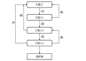
- the basic flow is a flow that proceeds in order of the flow lines (1), (2), and (3) in FIG. That is, the basic flow is to execute each step in the order of step (i) ⁇ step (ii) ⁇ step (iii) ⁇ step (iv).
- the effects of the present invention can be obtained by executing all the steps from step (i) to step (iv) at least once.
- the flow lines (1) and (4) are flow lines for repeatedly executing the step (i) and the step (ii). Repeating step (i) and step (ii) n times in order (n is a natural number) is expressed as [step (i) ⁇ step (ii)] n .
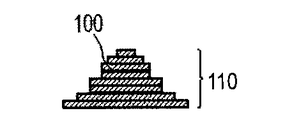
- [Step (i) ⁇ Step (ii)] n of n is characteristically used in the method of manufacturing a three-dimensional structure by the direct modeling method, and is the slice data generated from the three-dimensional shape data of the three-dimensional object to be manufactured. Corresponds to the number of slices n. Thereby, a modeled object having a desired shape based on the three-dimensional shape data can be obtained. For example, the shaped object 110 as shown in FIG.
- 1G is obtained by repeatedly executing the process (i) and the process (ii). 1A to 1H, first, the powder 101 is placed on the base 130, and the powder layer 102 is formed using the roller 152 (FIGS. 1A and 1B). This operation corresponds to step (i). Next, when the surface of the powder layer 102 is irradiated with the energy beam emitted from the energy beam source 180 while scanning the irradiation range 182 based on the slice data with the scanner unit 181, the powder is melted and then solidified to 1. A layered object 100 is formed (FIG. 1C). This operation corresponds to step (ii). The stage 151 is lowered, a powder layer 102 is newly formed on the shaped article 100 (FIG.
- the flow lines (3) and (6) are flow lines for repeatedly executing the steps (iii) and (iv). Repeating the step (iii) and the step (iv) m times (m is a natural number) in order is expressed as [step (iii) ⁇ step (iv)] m . [Step (i) ⁇ Step (ii)] [Step (iii) ⁇ Step (iv)] m can be executed after an intermediate shaped article having a desired shape is obtained by n .
- the number of repetitions m of the step (iii) and the step (iv) is a eutectic in which the vicinity of the microcrack of the model is about 22 mol% of zirconium oxide with respect to 78 mol% of the intermediate model of aluminum oxide as a main component. It is good to decide to approach the composition. Thereby, the microcrack vicinity becomes easy to fuse
- the zirconium component diffuses into the shaped object every time it is repeated. Then, the concentration difference of the zirconium component becomes small at a portion other than the vicinity of the microcrack portion and the vicinity of the microcrack portion of the molded article. Thereby, the difference between the melting point (eutectic point) in the vicinity of the microcrack portion of the shaped article and the melting point other than in the vicinity of the microcrack portion is reduced. From the viewpoint of melting only the vicinity of the microcrack portion, the difference in the melting points is preferably 20 ° C. or higher, more preferably 30 ° C. or higher.
- the zirconium component in the modeled object is less than 3 mol% for a modeled object made of powder containing aluminum oxide as a main component, only the vicinity of the microcracks is melted while suppressing the shape change of the modeled object. This is preferable. More preferably, it is less than 2 mol%.
- the zirconium component contained in the raw material powder is preferably less than 1 mol%.
- the shaped article that has finished the step (iv) is configured to include phases having greatly different average particle diameters of grains, so that machining of the shaped article as described above is performed. The effect which improves property can be acquired reliably.
- the raw material powder contains a zirconium component (for example, zirconium oxide) at a content of 3 mol% or more, it is difficult to locally melt only the vicinity of the microcrack portion in the heating process, and the molded article may be deformed. There is.
- the flow lines (1), (2), and (5) are flow lines for re-executing the process (i) and the process (ii) after the process (iii).
- a process (iii) is performed with respect to the intermediate molded object in the middle of forming the molded object 110 of a desired shape. Repeating step (i), step (ii), and step (iii) sequentially p times (p is a natural number) is expressed as [step (i) ⁇ step (ii) ⁇ step (iii)] p .
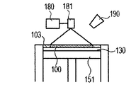
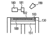
- An example in which the flow lines (1), (2) and (5) are applied to the powder bed direct shaping method is shown in FIGS. 4A to 4H.
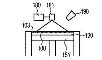
- the powder 101 is mounted on the base 130, and the powder layer 102 is formed using the roller 152 (FIGS. 4A and 4B).
- This operation corresponds to step (i).
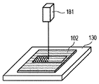
- the surface of the powder layer 102 is irradiated with the energy beam emitted from the energy beam source 180 while being scanned by the scanner unit 181, the powder is melted and then solidified to form the shaped article 100 (FIG. 4C).
- This operation corresponds to step (ii).
- a zirconia component-containing liquid is sprayed from the liquid jet nozzle 190 to the molded article 100 (FIG. 4D). This operation corresponds to step (iii).
- step (i) a powder layer 102 is newly formed on the shaped article 100
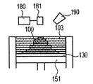
- step (i) These series of steps are repeated to form a shaped article 110 having a desired shape impregnated with the zirconia component-containing liquid (FIGS. 4G and 4H).
- the process (iii) is performed on the modeled object in the middle of modeling by the flow lines (1), (2), and (5), the size of the final modeled object is particularly large. Since the zirconia component-containing liquid can be sufficiently distributed to the inside of the modeled object, the effect of reducing or eliminating microcracks is enhanced.
- the flow lines (1), (2), (3), and (7) are flow lines for performing the step (i), the step (ii), and the step (iii) again after the step (iv).
- the step (iv) is performed on the intermediate model in the middle of forming the final intermediate model. Repeat step (i), step (ii), step (iii) and step (iv) in order q times (q is a natural number) [step (i) ⁇ step (ii) ⁇ step (iii) ⁇ step (iv) )] Indicated as q .
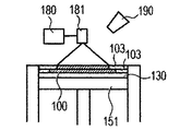
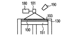
- An example in which the flow lines (1), (2), (3) and (7) are applied to the powder bed direct shaping method is shown in FIGS. 5A to 5I.
- the powder 101 is mounted on the base 130, and the powder layer 102 is formed using the roller 152 (FIGS. 5A and 5B).
- This operation corresponds to step (i).
- the surface of the powder layer 102 is irradiated with the energy beam emitted from the energy beam source 180 while being scanned by the scanner unit 181, the powder is melted and then solidified to form the shaped article 100 (FIG. 5C).
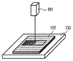
- This operation corresponds to step (ii).
- a zirconia component-containing liquid is sprayed from the liquid jet nozzle 190 onto the intermediate shaped article 100 (FIG. 5D). This operation corresponds to step (iii).
- step (iv) (FIG. 5E).
- step (i) (FIG. 5E).
- step (i) (FIG. 5F).
- step (i) (FIG. 5H)
- step (i) (FIG. 5I)
- steps (i) to (iv) the flow (4), (5), (6), (7) is arbitrarily added to the flow lines (1), (2), (3). Can be executed over and over again.
- the ceramic article of the present invention preferably has a phase separation structure composed of at least three phases of X phase, Y phase and Z phase, and the materials constituting the three phases are in a eutectic relationship.
- the average particle size x of the grains constituting the X phase, the average particle size y of the grains constituting the Y phase, and the average particle size z of the grains constituting the Z phase are z / x ⁇ 0.5 and Those satisfying the relationship of z / y ⁇ 0.5 are preferable.
- an average particle diameter is an average value of the circle equivalent diameter of the crystal grain observed in the cross section of a ceramic molded article.
- the ceramic shaped article of the present invention composed of a three-phase eutectic phase separation structure of X phase, Y phase, and Z phase has an excellent three-point bending strength of, for example, 30 MPa or more because progress of cracks and the like is suppressed.
- Ceramic shaped objects in which the particle sizes x and y of the X phase and the Y phase and the particle size z of the Z phase are in the relationship of z / x ⁇ 0.5 and z / y ⁇ 0.5 It is considered that the Z phase having a relatively small diameter functions to connect other phases having a relatively large particle diameter. Therefore, the molded article has excellent workability (stickiness) with less chipping during machining while having high mechanical strength. In addition, wear resistance is improved. From this point of view, more preferable relationships of x, y, and z are z / x ⁇ 0.35 and z / y ⁇ 0.35.
- the particle sizes of the X phase and the Y phase are large to some extent, because the porosity of the model can be reduced and the denseness can be increased.
- x and y are preferably 3 ⁇ m or more, and more preferably 5 ⁇ m or more.
- x and y are preferably 30 ⁇ m or less.
- the ceramic shaped article of the present invention can have better workability.
- z is preferably smaller, specifically, less than 5 ⁇ m. More preferable z is less than 3 ⁇ m.
- the ceramic shaped article of the present invention is preferably produced by applying the manufacturing method of the present invention described above.
- a preferable combination of the three phases is a phase mainly composed of Al 2 O 3 , a phase mainly composed of rare earth aluminate, and a phase mainly composed of ZrO 2 .
- Al 2 O 3 , rare earth aluminate and ZrO 2 are in a eutectic relationship, and a complicated phase separation structure composed of three phases can be stably formed.
- Preferred rare earths constituting the rare earth aluminate include gadolinium, yttrium, terbium and the like, and preferred rare earth aluminates include GdAlO 3 , Y 3 Al 5 O 12 and the like.
- the crystal structure of each phase varies somewhat depending on the manufacturing process, but each of the three-phase eutectics is preferably composed of the crystal structure as described above.
- ZrO 2 having a fluorite structure are mainly composed.
- Al 2 O 3 powder and Gd 2 O 3 powder are preferably mixed so as to have a eutectic composition to obtain a mixed powder.
- the mixed powder is placed on a base (corresponding to step (i)) and irradiated with an energy beam to melt and solidify the mixed powder to obtain a shaped object (corresponding to step (ii)).
- the shaped article formed in this way includes at least part of two phases of Al 2 O 3 —GdAlO 3 .
- a microcrack is formed in a molded article.
- the zirconium component By absorbing the zirconium component-containing liquid in the shaped article, the zirconium component is distributed in the microcrack portion of the shaped article (corresponding to step (iii)). Then shaped object the Al 2 O 3 -GdAlO 3 -ZrO 2 of 3-phase eutectic point or higher, Al 2 O 3 is preferably heated at a temperature below the eutectic point of the two-phase -GdAlO 3 (step (iv )). For example, in the case of this material system, it is preferable to heat at a temperature of about 1650 ° C. or higher and 1710 ° C. or lower.
- the shaped object is recrystallized in a state where the zirconium component is taken in, and a phase mainly composed of ZrO 2 having a fluorite structure, a phase mainly composed of Al 2 O 3 , and a phase mainly composed of GdAlO 3. And a three-phase eutectic model.
- the average particle size of the grains constituting each of the phase mainly composed of Al 2 O 3 and the phase mainly composed of GdAlO 3 that were originally present in the molded product before the heating step of step (iv) is It grows with heating.
- the average particle size of the grains constituting the phase mainly composed of ZrO 2 formed for the first time in the step (iv) is smaller than the average particle size of the other two phases.
- a phase having ZrO 2 as a main component which has an average particle size smaller than that of the other phases, is formed on the modeled object, thereby increasing the bonding force between the crystal structures of the modeled object.
- the wear resistance is greatly improved. At the same time, it becomes a shaped product with high machinability, capable of precise finishing with few chipped grains.
- the powder is melted and solidified by irradiation with an energy beam to produce a molded article having microcracks that communicate with the interior, and the components that form a eutectic with the constituent materials of the molded article are distributed to the microcracks. Heating is an important point.
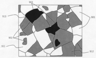
- FIG. 9A is a diagram schematically showing the phase separation structure and the size relationship of the crystal grains constituting each phase, which are observed in the cross section of the ceramic article of the present invention.
- the crystal grains 811 constituting the X phase and the crystal grains 812 constituting the Y phase have a phase separation structure composed of three phases of the X phase 801, the Y phase 802, and the Z phase 803.
- the crystal grains 813 constituting the Z phase The average particle size is larger.
- FIG. 9B schematically shows a cross-sectional state of a conventional ceramic article obtained by mixing raw materials powder, forming, heating and sintering. Although it has a three-phase eutectic phase separation structure, there is no significant difference between the grain sizes of the crystal grains constituting each phase.
- Ceramics having such a configuration is not excellent in machinability and cannot exhibit the effects of the present invention.
- a ceramic structure formed by a three-phase eutectic composed of a phase mainly composed of Al 2 O 3 , a phase mainly composed of rare earth aluminate, and a phase mainly composed of ZrO 2 is A complex phase separation structure is stably formed by the production method of the present invention, which is preferable.
- the most preferable ceramic model is a model in which the phase mainly composed of Al 2 O 3 is the X phase, the phase mainly composed of the rare earth aluminate is the Y phase, and the phase mainly composed of ZrO 2 is the Z phase. is there.
- a modeled object having such a separation layer structure is first prepared so as to include a two-phase eutectic of Al 2 O 3 -rare earth aluminate. Then, the spread of the zirconium component in the microcracks of the contrast forms thereof, Al 2 O 3 - rare earth aluminate -ZrO 2 of 3-phase eutectic point or higher, Al 2 O 3 - less than 2-phase eutectic point of the rare earth aluminate It can produce by heating at the temperature of.
- a three- phase eutectic point has a three-phase eutectic point when a phase mainly composed of Al 2 O 3 is an X phase, a phase mainly composed of a rare earth aluminate is a Y phase, and a phase mainly composed of ZrO 2 is a Z phase. It becomes 1600 degreeC or more and 1700 degrees C or less.
- the three-phase eutectic point of the ceramic shaped article is 1700 ° C. or lower, sufficient soaking is obtained in the shaped article during heating corresponding to step (iv). Therefore, only the microcrack part of the entire modeled object can be locally melted, and the effect of improving the mechanical strength can be obtained while maintaining the shape of the modeled object.
- the three-phase eutectic point is 1600 ° C. or higher because it is possible to produce a ceramic article that requires heat resistance.
- the ceramic shaped object composed of a three-phase eutectic composed of a phase mainly composed of Al 2 O 3 , a phase mainly composed of rare earth aluminate, and a phase mainly composed of ZrO 2 , the ceramic shaped object
- the combination of materials corresponding to the X phase, Y phase, and Z phase is not limited.
- a shaped article may be produced so as to include a rare earth aluminate-ZrO 2 two-phase eutectic, and then the aluminum component may be distributed inside the shaped article and heated.
- the rare earth aluminate-ZrO 2 two phases become the X phase and the Y phase having a relatively large particle size
- Al 2 O 3 becomes the Z phase having a relatively small particle size.
- the ceramic article which has can be obtained.
- a shaped article may be produced so as to include a two-phase eutectic of Al 2 O 3 —ZrO 2 , and then the rare earth component may be distributed inside the shaped article and heated.
- the two phases of Al 2 O 3 —ZrO 2 become the X phase and the Y phase having a relatively large particle size, and the rare earth aluminate becomes the Z phase having a relatively small particle size. Can be obtained.
- the Z phase is preferably a metal oxide having a fluorite structure. Thereby, it becomes easy to obtain the effects of improving the wear resistance and workability described above.
- the Z phase contains a rare earth element because the Z phase is stably formed.
- the ratio of the rare earth element contained in the Z phase is 0.20 mol or more and 0.40 mol or less with respect to 1 mol of the other metal elements contained in the Z phase, a Z phase having sufficient temperature stability can be obtained. Therefore, it is more preferable. More preferably, it is 0.25 mol or more and 0.35 mol or less.
- the main component of the Z phase is preferably zirconium oxide or hafnium oxide.
- the Z phase contains zirconium oxide or hafnium oxide, a shaped article having high mechanical strength is obtained.
- the Z phase is composed mainly of zirconium oxide or hafnium oxide, among the metal elements constituting the ceramic shaped article, the zirconium element and the hafnium element are 0.2 mol% or more, and the ceramic shaped article is sufficient. A sufficient amount of Z phase is formed, and the effect of improving wear resistance and workability is obtained. It is preferable that the zirconium element and the hafnium element are less than 3 mol% among the metal elements constituting the ceramic shaped article, since the expansion of the Z phase particle size can be suppressed.
- the ceramic shaped article of the present invention can be produced. Specifically, a model is first prepared from a powder of a material that forms a two-phase eutectic relationship. Then, the material forming the two-phase eutectic relationship and the component forming the three-phase eutectic relationship are distributed to the microcrack portion of the modeled object, and the three-phase eutectic point or higher and originally included in the modeled object. It can be produced by heating at a temperature below the two-phase eutectic point.
- the mechanical strength of a shaped article can be evaluated by a three-point bending test based on R1601, which is a JIS standard for room temperature bending strength testing of fine ceramics.
- the three-point bending strength is P [N] when the test piece breaks, L [mm] between the external fulcrums, w [mm] of the test piece, and t [mm] of the test piece. ] 3 ⁇ P ⁇ L / (2 ⁇ w ⁇ t 2 ) (Equation 1).
- the wear resistance of the modeled object can be evaluated by the wear rate of the modeled object when the modeled object is shaved under a certain condition.
- the depletion rate D is an amount cut per unit time, and can be expressed as, for example, D [mm 3 / min]. The smaller the wear rate D, the better the wear resistance.
- the machinability of the modeled object can be evaluated by the number of chipped portions (chippings) at the edge of the cut surface when the modeled object is cut under a certain condition.
- Relative density [%] was calculated by dividing the bulk density (weight divided by volume) of the modeled object by the theoretical density.
- the theoretical density was calculated from the crystal structure.
- the crystal structure was identified by performing X-ray diffraction measurement and performing Rietveld analysis.
- the phase constituting the ceramic model can be examined by X-ray diffraction, electron beam diffraction, or the like.
- X-ray diffraction electron beam diffraction
- SEM scanning electron microscope
- EDX energy dispersive X-ray spectroscopy
- the grain size of the crystal grains constituting the phase is obtained by observing 300 or more crystal grains in the same phase in the cross section of the modeled object by EBSD or the like and calculating the average value of the equivalent circle diameter of each crystal grain. be able to.
- the amount of metal elements constituting powders and shaped objects is SEM-EDX, TEM-EDX, electron diffraction, inductively coupled plasma emission analysis (ICP-AES), inductively coupled plasma mass spectrometry (ICP-MS), Measurement can be performed using fluorescent X-ray analysis (XRF) or the like.
- Example 1 ⁇ Process (i) and process (ii)> ⁇ -Al 2 O 3 powder having an average particle diameter of about 20 ⁇ m, Gd 2 O 3 powder having an average particle diameter of about 35 ⁇ m, and Tb 2 O 3.5 powder (Tb 4 O 7 powder) having an average particle diameter of about 5 ⁇ m
- Each weighed powder was mixed with a dry ball mill for 30 minutes to obtain a mixed powder (raw material powder).
- the average particle diameter in the present invention is a median diameter is a particle size of which cumulative frequency is 50% (D 50).
- the zirconium oxide content was less than 1 mol%.
- Example 1 the shaped article of Example 1 was manufactured through the same steps as those shown in FIGS. 1A to 1H described above.
- ProX DMP 100 (trade name) manufactured by 3D SYSTEMS, on which a 50 W fiber laser (beam diameter: 65 ⁇ m) is mounted, was used.
- a 20 ⁇ m-thick first powder layer made of the raw material powder was formed on an alumina base using a roller (step (i)).
- a 30 W laser beam was applied to the powder layer, and the material powder in a rectangular area of 5 mm ⁇ 42 mm was melted and solidified.
- the drawing speed was set to 100 mm / s to 140 mm / s, and the drawing pitch was set to 100 ⁇ m. Further, as shown in FIG. 6A, the drawing line was positioned at an angle of 45 degrees with respect to each side of the rectangle.
- the powder layer was irradiated with a laser beam to melt and solidify the powder in a rectangular area of 5 mm ⁇ 42 mm (step (ii)).
- a 20 ⁇ m-thick powder layer was newly formed with a roller so as to cover the melted and solidified portion (step (i)).
- the powder layer just above the rectangular region was irradiated with a laser so as to be orthogonal to the first drawing line to melt and solidify the powder in the 5 mm ⁇ 42 mm region. (Step (ii)).
- Such a process was repeated to produce a prismatic shaped article having a bottom surface of 5 mm ⁇ 42 mm and a height of 6 mm for use in a three-point bending strength test.
- a square pillar-shaped shaped article with a bottom face of 6 mm square and a height of 6 mm was also prepared for the wear resistance test.
- the unevenness on the surface of the shaped objects was 30 ⁇ m or less.
- Each of the above-mentioned shaped objects is cut off from the alumina base and polished to obtain a three-point bending strength test W40 mm ⁇ D4 mm ⁇ H3 mm shaped object (FIG. 7A) and an abrasion resistance test W5 mm ⁇ D5 mm ⁇ H5 mm.
- a shaped object (FIG. 7B) was obtained.
- the modeled product processed for the test was immersed in the zirconium component-containing solution, degassed under reduced pressure for 1 minute, impregnated with the solution to the inside of the modeled product, and then naturally dried for 1 hour (step (iii)).
- the shaped article impregnated with the zirconium component-containing liquid was placed in an electric furnace and heated. The temperature was raised to 1670 ° C. in an air atmosphere in 2.5 hours, and the temperature was maintained at 1670 ° C. for 50 minutes. Then, the energization was completed and the temperature was lowered to 200 ° C. or less in 1.5 hours (step (iv)).
- Example 1 the step of impregnating the shaped article with the zirconium component-containing liquid (step (iii)) and the heat treatment step (step (iv)) were repeated four times alternately. Then, three shaped objects for a three-point bending strength test of W40 mm ⁇ D4 mm ⁇ H3 mm, one shaped object for the strength test and one for composition and structural evaluation, and a model for W5 mm ⁇ D5 mm ⁇ H5 mm wear resistance test One object was made.
- the wear resistance was evaluated by the following method.
- the modeled product of W5 mm ⁇ D5 mm ⁇ H5 mm of Example 1 was placed on a 600th diamond polishing disk (manufactured by Musashino Electronics Co., Ltd.) rotating at 80 rpm and cut with a load of 0.5 kg.
- the wear rate was 1.03 [mm 3 / min].
- Machinability was evaluated by investigating the number of defects on the edge of the cut surface during the wear resistance evaluation. Specifically, an arbitrary side 5 mm of the cut surface was observed with an optical microscope, and the number of missing portions in the side was examined. As the number of defects, the number of defects having a maximum chip width in the direction parallel to the one side of 50 ⁇ m or more and a maximum chip width in the direction perpendicular to the one side of 50 ⁇ m or more was counted. When the number of missing parts was 0, A, 1 or more and 3 or less, B and 4 or more, C, and the machinability was evaluated. The number of missing portions in Example 1 was 0, and the machinability rank was excellent as A.
- the shaped object is polished to a mirror surface, and the crystal structure and composition of the phases constituting the shaped object are examined by X-ray diffraction, electron beam diffraction, SEM-EDX and TEM-EDX, and the phase separation structure and each phase are constituted.
- the average grain size of the crystal grains was analyzed by SEM-EBSD.
- the modeled object of Example 1 was composed of three phases: a phase composed of Al 2 O 3 , a phase composed of GdAlO 3 , and a phase mainly composed of zirconium oxide having a fluorite structure.
- the average grain sizes of the crystal grains constituting the phase composed of Al 2 O 3 , the phase composed of GdAlO 3 and the phase mainly composed of zirconium oxide having a fluorite structure are 8.3 ⁇ m, 9.5 ⁇ m, .6 ⁇ m.
- the main metal elements constituting the phase mainly composed of zirconium oxide having a fluorite structure were Zr, Gd, and Tb, and the metal elements other than Zr, Gd, and Tb were less than 1 mol%.
- the ratio of rare earth elements was 30 mol% on average.
- the ICP-AES analysis and ICP-MS analysis of the modeled object were performed to examine the amount of Zr element contained in the modeled object.
- the amount of Zr element was 0.9 mol%.
- Examples 2 to 5 ⁇ Process (i) and process (ii)>
- a W40 mm ⁇ D4 mm ⁇ H3 mm intermediate shaped product for the three-point bending strength test and a W5 mm ⁇ D5 mm ⁇ H5 mm shaped product for the wear resistance test were prepared.
- the unevenness on the surface of the shaped object was 30 ⁇ m or less.
- step (iii) and process (iv) the same zirconium component-containing solution as in Example 1 was used.
- the step of immersing the shaped article in the zirconium component-containing liquid (step (iii)) and the step of heating the shaped article impregnated with the zirconium component-containing liquid (step (iv)) are also performed under the same conditions as in Example 1. It was.
- step (iii) and step (iv) were performed once in order.
- step (iii) and step (iv) were repeated twice alternately.
- step (iii) and step (iv) were repeated 3 times alternately.
- step (iii) and step (iv) were repeated 5 times alternately. In this way, for each of Examples 2 to 5, four shaped objects of W40 mm ⁇ D4 mm ⁇ H3 mm and one shaped object of W5 mm ⁇ D5 mm ⁇ H5 mm were obtained.
- Example 1 As in Example 1, for each of the shaped objects of Examples 2 to 5, the three-point bending strength, the depletion rate, the relative density, the machinability evaluation, and the crystal structure and composition of the phases constituting the shaped object, The phase separation structure and the average grain size of the crystal grains constituting each phase were analyzed.
- Table 1 shows the measurement evaluation results of the three-point bending strength, depletion rate, relative density, and machinability of Examples 2 to 5 together with the results of Example 1.
- the shaped objects of Examples 2 to 5 were composed of three phases: a phase composed of Al 2 O 3 , a phase composed of GdAlO 3 , and a phase mainly composed of zirconium oxide having a fluorite structure.
- the phase made of Al 2 O 3 of the modeled object of each example is called the X1 phase
- the phase made of GdAlO 3 is called the Y1 phase
- the phase mainly composed of zirconium oxide having a fluorite structure is called the Z1 phase.
- the average grain sizes x1, y1, and z1 of the crystal grains constituting the X1 phase, the Y1 phase, and the Z1 phase are set.
- Table 2 shows the analysis results of the ratio of the rare earth element in the metal element contained in the Z1 phase and the ratio of the Zr element in the metal element constituting the modeled object together with the result of Example 1.
- Example 1 the three-dimensional bending strength, the wear rate, the relative density, the machinability evaluation, and the crystal structure and composition of phases constituting the three-dimensional object, and the phase-separated structure are also obtained for the three-dimensional object of Comparative Example 1.
- the average grain size of the crystal grains constituting each phase was analyzed.
- Table 1 shows the measurement evaluation results of 3-point bending strength, wear rate, relative density, and machinability.
- the shaped object of Comparative Example 1 was composed of a phase made of Al 2 O 3 , a phase made of GdAlO 3 , and an amorphous phase having a composition fluctuation. These phases are not in a three-phase eutectic relationship. Moreover, there was no phase mainly composed of zirconium oxide having a fluorite structure.
- Example 2 Comparative Example 2 Except that the step of impregnating the shaped component with the zirconium component-containing liquid was not performed, the molded product of W40 mm ⁇ D4 mm ⁇ H3 mm for the three-point bending strength test and the wear resistance test were performed in the same manner as in Example 1. A shaped product of W5 mm ⁇ D5 mm ⁇ H5 mm was prepared. Only the step (step (iii)) of immersing the shaped article in the zirconium component-containing solution was omitted, and the shaped article was placed in an electric furnace and subjected to heat treatment. After raising the temperature to 1670 ° C. in an air atmosphere for 2.5 hours and holding at 1670 ° C.
- Example 2 the three-dimensional bending strength, the depletion rate, the relative density, the machinability evaluation, and the crystal structure and composition of the phases constituting the model, and the phase separation structure of the model 2 of Comparative Example 2 The average grain size of the crystal grains constituting each phase was analyzed.
- the shaped article of Comparative Example 2 was composed of two phases, a phase made of Al 2 O 3 and a phase made of GdAlO 3 . There was no phase composed mainly of zirconium oxide with a fluorite structure.
- a PVA (polyvinyl alcohol) binder dissolved in pure water is added to the mixed powder so as to be 3 parts by weight, mixed in a mortar and dried, and then pulverized and mixed for 10 hours in a dry ball mill.
- the granulated powder is put into a mold, pressed into a disk shape having a thickness of 3 mm and a diameter of 1 cm, heated to 600 ° C. in an air atmosphere over 1 hour, held at 600 ° C. for 3 hours, and then from 600 ° C. to 1650 ° C.
- the mixture was heated up to 2 hours and fired at 1650 ° C. for 2 hours.
- the baked comparative ceramics had large irregularities such as undulations of 100 to 300 ⁇ m on the surface and side surfaces.
- the manufacturing method of the comparative example 3 cannot produce the molded object for evaluation of W40mmxD4mmxH3mm shape, and cannot perform a 3 point
- a block of W5 mm ⁇ D5 mm ⁇ H2 mm was cut out from the disk while avoiding irregularities, and the same abrasion resistance test as in Example 1 was performed on the W5 mm ⁇ D5 mm surface.
- Table 1 shows the evaluation results of wear rate, relative density, and machinability.
- the ceramic shaped article of Comparative Example 3 was composed of three phases: a phase composed of Al 2 O 3 , a phase composed of GdAlO 3 , and a phase mainly composed of zirconium oxide. Later, Al 2 O 3 from consisting phases X2 phase comparison ceramics of Comparative Example 3, the phases Y2 phase consisting of GdAlO 3, a phase composed mainly of zirconium oxide say Z2 phase.
- the average grain sizes x2, y2, and z2 of the crystal grains constituting the X2, Y2, and Z2 phases were 21 ⁇ m, 25 ⁇ m, and 15 ⁇ m, respectively.
- FIG. 8A is an optical microscope image of the modeled object of Comparative Example 1
- FIG. 8B is an optical microscope image of the modeled object of Example 1.
- each of the shaped articles of Examples 1 to 5 produced by the manufacturing method of the present invention has a significantly improved three-point bending strength and wear compared to the shaped article of Comparative Example 1. It can be seen that the speed is greatly reduced. This shows that the mechanical strength and wear resistance of the shaped article can be greatly improved according to the method for producing a shaped article of the present invention.
- Example 4 the three-point bending strength was greatly improved and the depletion rate was greatly reduced as compared with Comparative Example 2 which was different only in that the zirconium-containing solution was not impregnated. From this result, it can be seen that the step (iii) of impregnating the intermediate shaped article with the zirconium component-containing liquid of the present invention greatly contributes to the improvement of mechanical strength and wear resistance.
- the machinability of Examples 1, 4 and 5 satisfying z1 / x1 ⁇ 0.3 and z1 / y1 ⁇ 0.3 is A rank, and B ranks of Examples 2 and 3 are used. Was even better than.
- the unevenness of the surface of the model was 30 ⁇ m or less.
- Comparative Example 3 as a result of firing at a high temperature close to the eutectic point, a high relative density can be obtained due to partial melting. Unevenness of 300 ⁇ m was observed.
- Comparative Example 3 it has been found difficult to produce a structure having both density and shape accuracy by the production method of Comparative Example 3. Therefore, it has been confirmed that the manufacturing method of the present invention enables modeling with higher modeling accuracy than the manufacturing method of the comparative example.
- the method for manufacturing a molded article according to the present invention it is possible to improve the mechanical strength, wear resistance, and machinability of the molded article while obtaining high modeling accuracy. Furthermore, by adjusting the number of times the process containing the zirconium-containing solution and the heat treatment process are performed on a modeled product mainly composed of aluminum oxide, high mechanical accuracy and wear resistance can be achieved depending on the application while achieving high modeling accuracy. Ceramic articles with improved properties and machinability can be obtained.
- Example 2 the shaped objects of Examples 6 and 7 were produced in the same process.
- the laser irradiation conditions were changed such that the laser beam output was 47.5 W, the drawing speed was 60 mm / s, and the drawing pitch was 80 ⁇ m.
- a laser beam is irradiated into a rectangular region of 5 mm ⁇ 42 mm of the powder layer to melt the powder.
- solidifying step (ii) was repeated.
- a modeled object having a prismatic shape with a bottom surface of 5 mm ⁇ 42 mm and a height of 6 mm and a porosity of about 20% was obtained.
- the surface of the modeled object was observed with an optical microscope, the surface of the modeled object was 30 ⁇ m or less.
- the manufactured model was cut off from the alumina base and polished to obtain a W40 mm ⁇ D4 mm ⁇ H3 mm model (FIG. 7A) for a three-point bending strength test.
- step (iii) The shaped product processed for the test was impregnated with a zirconium component-containing liquid and dried naturally (step (iii)) in the same manner as in Example 1.
- the shaped article impregnated with the zirconium component-containing liquid was placed in an electric furnace and heated. Specifically, the temperature was raised to 1685 ° C. in an air atmosphere in 2.5 hours, held at 1685 ° C. for 50 minutes, then energized and cooled to 200 ° C. or less in 1.5 hours (step (iv)) ).
- Example 6 a step (step (iii)) of impregnating a shaped article with a zirconium component-containing liquid and a heat treatment step (step (iv)) are each performed once for a three-point bending strength test of W40 mm ⁇ D4 mm ⁇ H3 mm. 1 model was obtained.
- Example 7 the process (iii) and the process (iv) were alternately repeated twice to obtain one shaped object of W40 mm ⁇ D4 mm ⁇ H3 mm.
- step (iii) a shaped article was produced in the same manner as in Examples 6 and 7, except that an aluminum component-containing liquid was used and the conditions of step (iv) were changed accordingly.
- the aluminum component-containing solution was prepared by dissolving aluminum sec-butoxide in 2-propanol (IPA) and adding ethyl acetoacetate (EAcAc) as a stabilizer.
- the aluminum component containing liquid was prepared by stirring at room temperature for about 3 hours.
- the modeled product processed for the test was immersed in the aluminum component-containing solution, degassed under reduced pressure for 1 minute, allowed to penetrate into the modeled product, and then naturally dried for 1 hour (step (iii)).
- the intermediate shaped article impregnated with the aluminum component-containing liquid as described above was placed in an electric furnace and heated. Specifically, the temperature was raised to 1600 ° C. in an air atmosphere in 2 hours, held at 1600 ° C. for 30 minutes, energization was terminated, and the temperature was lowered to 200 ° C. or less in 1.5 hours (step (iv)).
- Example 8 the step (step (iii)) of impregnating the shaped article into the aluminum component-containing liquid and the heat treatment step (step (iv)) are each performed once for a three-point bending strength test of W40 mm ⁇ D4 mm ⁇ H3 mm. 1 model was obtained.
- Example 9 the process (iii) and the process (iv) were alternately repeated twice to obtain one shaped object of W40 mm ⁇ D4 mm ⁇ H3 mm.
- Example 2 As in Example 1, for the three-point bending test, the three-point bending strength was measured using a compression tester manufactured by Instron. Table 3 shows the three-point bending strength of each one of W6 mm ⁇ D4 mm ⁇ H3 mm of each of Examples 6 to 9 and Comparative Example 4.
- the manufacturing method of the present invention it is possible to obtain a ceramic article having high mechanical accuracy and high mechanical strength depending on the application.
- the ceramic article according to the present invention can realize high mechanical strength according to the application, and can also realize high wear resistance and machinability.
- a modeled object that can further improve the mechanical strength, wear resistance, and machinability of the modeled object while utilizing the features of the direct modeling method that can obtain a modeled object having a dense and complicated shape as it is.
- the manufacturing method of can be provided.
Landscapes
- Chemical & Material Sciences (AREA)
- Engineering & Computer Science (AREA)
- Ceramic Engineering (AREA)
- Manufacturing & Machinery (AREA)
- Materials Engineering (AREA)
- Structural Engineering (AREA)
- Organic Chemistry (AREA)
- Inorganic Chemistry (AREA)
- Mechanical Engineering (AREA)
- Composite Materials (AREA)
- Chemical Kinetics & Catalysis (AREA)
- General Chemical & Material Sciences (AREA)
- Dispersion Chemistry (AREA)
- Powder Metallurgy (AREA)
- Producing Shaped Articles From Materials (AREA)
- Compositions Of Oxide Ceramics (AREA)
Priority Applications (4)
| Application Number | Priority Date | Filing Date | Title |
|---|---|---|---|
| CN201980035063.1A CN112166018B (zh) | 2018-04-24 | 2019-04-23 | 陶瓷产品制造方法和陶瓷产品 |
| EP19791494.8A EP3769924A4 (en) | 2018-04-24 | 2019-04-23 | CERAMIC PRODUCT MANUFACTURING PROCESS, AND CERAMIC PRODUCT |
| US17/076,328 US12059819B2 (en) | 2018-04-24 | 2020-10-21 | Ceramics product manufacturing method and ceramics product |
| US18/753,120 US12409579B2 (en) | 2018-04-24 | 2024-06-25 | Ceramics product manufacturing method and ceramics product |
Applications Claiming Priority (4)
| Application Number | Priority Date | Filing Date | Title |
|---|---|---|---|
| JP2018-083110 | 2018-04-24 | ||
| JP2018083110 | 2018-04-24 | ||
| JP2019081158A JP7269084B2 (ja) | 2018-04-24 | 2019-04-22 | セラミックス物品の製造方法およびセラミックス物品 |
| JP2019-081158 | 2019-04-22 |
Related Child Applications (1)
| Application Number | Title | Priority Date | Filing Date |
|---|---|---|---|
| US17/076,328 Continuation US12059819B2 (en) | 2018-04-24 | 2020-10-21 | Ceramics product manufacturing method and ceramics product |
Publications (1)
| Publication Number | Publication Date |
|---|---|
| WO2019208570A1 true WO2019208570A1 (ja) | 2019-10-31 |
Family
ID=68295021
Family Applications (1)
| Application Number | Title | Priority Date | Filing Date |
|---|---|---|---|
| PCT/JP2019/017244 Ceased WO2019208570A1 (ja) | 2018-04-24 | 2019-04-23 | セラミックス物品の製造方法及びセラミックス物品 |
Country Status (5)
| Country | Link |
|---|---|
| US (2) | US12059819B2 (enExample) |
| EP (1) | EP3769924A4 (enExample) |
| JP (3) | JP7269084B2 (enExample) |
| CN (1) | CN112166018B (enExample) |
| WO (1) | WO2019208570A1 (enExample) |
Cited By (5)
| Publication number | Priority date | Publication date | Assignee | Title |
|---|---|---|---|---|
| WO2021079907A1 (ja) * | 2019-10-23 | 2021-04-29 | キヤノン株式会社 | セラミックス物品の製造方法、金属成分含有液、セラミックス物品製造用キットおよびセラミックス物品 |
| WO2021079909A1 (ja) * | 2019-10-23 | 2021-04-29 | キヤノン株式会社 | セラミックス物品の製造方法およびセラミックス物品 |
| JP2021066177A (ja) * | 2019-10-23 | 2021-04-30 | キヤノン株式会社 | セラミックス物品の製造方法、およびセラミックス物品 |
| WO2022080318A1 (ja) * | 2020-10-16 | 2022-04-21 | キヤノン株式会社 | セラミックス物品の製造方法、それに用いられる金属イオン含有液およびセラミックス物品製造用キット |
| US12059819B2 (en) | 2018-04-24 | 2024-08-13 | Canon Kabushiki Kaisha | Ceramics product manufacturing method and ceramics product |
Families Citing this family (2)
| Publication number | Priority date | Publication date | Assignee | Title |
|---|---|---|---|---|
| JP7614720B2 (ja) | 2018-12-21 | 2025-01-16 | キヤノン株式会社 | 無機材料粉末、および構造体の製造方法 |
| US20210362417A1 (en) * | 2020-05-25 | 2021-11-25 | Canon Kabushiki Kaisha | Packaged 3-dimensional modeling powder material and 3-dimensional modeling system |
Citations (6)
| Publication number | Priority date | Publication date | Assignee | Title |
|---|---|---|---|---|
| JPS62113781A (ja) * | 1985-11-12 | 1987-05-25 | 日立金属株式会社 | セラミツクス焼結体の製造方法 |
| JP2001017907A (ja) * | 1999-07-08 | 2001-01-23 | Tsutomu Minami | 表面微細凹凸組織の低温形成法および当該組織を有する基体 |
| JP2013501701A (ja) * | 2009-08-10 | 2013-01-17 | ベゴ・ブレーマー・ゴルトシュレーゲライ・ヴィルヘルム・ヘルプスト・ゲゼルシャフト・ミット・ベシュレンクテル・ハフツング・ウント・コムパニー・コマンディットゲゼルシャフト | セラミック又はガラスセラミック物品及び該物品の製造方法 |
| JP2016204244A (ja) * | 2014-09-18 | 2016-12-08 | Toto株式会社 | 反応焼結炭化ケイ素部材の製造方法 |
| JP2018083110A (ja) | 2018-01-26 | 2018-05-31 | カシオ計算機株式会社 | 心拍計測装置及び心拍計測方法、心拍計測プログラム |
| JP2019081158A (ja) | 2017-10-31 | 2019-05-30 | アルプスアルパイン株式会社 | 振動発生装置 |
Family Cites Families (22)
| Publication number | Priority date | Publication date | Assignee | Title |
|---|---|---|---|---|
| JP3176815B2 (ja) * | 1995-01-19 | 2001-06-18 | 富士電機株式会社 | 半導体装置用基板 |
| US5675181A (en) | 1995-01-19 | 1997-10-07 | Fuji Electric Co., Ltd. | Zirconia-added alumina substrate with direct bonding of copper |
| US20040247479A1 (en) * | 2003-06-04 | 2004-12-09 | Lockheed Martin Corporation | Method of liquid phase sintering a two-phase alloy |
| US7598188B2 (en) * | 2005-12-30 | 2009-10-06 | 3M Innovative Properties Company | Ceramic materials and methods of making and using the same |
| CN1958196A (zh) * | 2006-09-21 | 2007-05-09 | 中北大学 | 钼铜复合材料高温构件的快速制作方法 |
| JP2013032265A (ja) * | 2011-07-01 | 2013-02-14 | Maruwa Co Ltd | 半導体装置用アルミナジルコニア焼結基板及びその製造方法 |
| GB201209415D0 (en) | 2012-05-28 | 2012-07-11 | Renishaw Plc | Manufacture of metal articles |
| DE102012110322B4 (de) * | 2012-10-29 | 2014-09-11 | Rogers Germany Gmbh | Metall-Keramik-Substrat sowie Verfahren zum Herstellen eines Metall-Keramik-Substrates |
| JP6164824B2 (ja) * | 2012-11-30 | 2017-07-19 | キヤノン株式会社 | 光学用部材及びその製造方法 |
| JP6514227B2 (ja) * | 2014-02-21 | 2019-05-15 | ポリテクニコ ディ トリノ | ジルコニア系多相セラミック複合材料の製造方法 |
| WO2016098767A1 (ja) * | 2014-12-16 | 2016-06-23 | 日本碍子株式会社 | セラミック素地及びその製造方法 |
| US10875093B2 (en) * | 2015-07-17 | 2020-12-29 | Applied Materials, Inc. | Selective material dispensing in additive manufacturing |
| JP6546135B2 (ja) * | 2016-08-24 | 2019-07-17 | 株式会社ノリタケカンパニーリミテド | 積層造形焼成体、積層造形焼成体の製造方法および積層造形焼成体製造用キット |
| CN107140959A (zh) * | 2017-04-26 | 2017-09-08 | 西北工业大学 | 一种氧化物共晶结构陶瓷粉末的制备方法 |
| CN107140960B (zh) * | 2017-04-26 | 2021-01-05 | 西北工业大学 | 放电等离子烧结氧化铝基共晶陶瓷复合材料的方法 |
| JP7011548B2 (ja) | 2017-07-14 | 2022-01-26 | キヤノン株式会社 | セラミックス造形用粉体、セラミックス造形物、およびその製造方法 |
| DE102017116141B4 (de) * | 2017-07-18 | 2025-04-30 | Arianegroup Gmbh | Faserverbundwerkstoff und Verfahren zu dessen Herstellung |
| CN107663081B (zh) * | 2017-10-26 | 2020-09-08 | 西北工业大学 | 氧化铝基三元纳米共晶/非晶陶瓷的凝固制备方法 |
| US11285661B2 (en) | 2017-11-08 | 2022-03-29 | Canon Kabushiki Kaisha | Powder for ceramic shaping and ceramic shaping method using the same |
| US10759712B2 (en) | 2017-11-09 | 2020-09-01 | Canon Kabushiki Kaisha | Powder for additive modeling, structure, semiconductor production device component, and semiconductor production device |
| JP7269084B2 (ja) | 2018-04-24 | 2023-05-08 | キヤノン株式会社 | セラミックス物品の製造方法およびセラミックス物品 |
| JP2025113781A (ja) | 2024-01-23 | 2025-08-04 | キヤノン株式会社 | 情報処理装置、情報処理方法及びプログラム |
-
2019
- 2019-04-22 JP JP2019081158A patent/JP7269084B2/ja active Active
- 2019-04-23 WO PCT/JP2019/017244 patent/WO2019208570A1/ja not_active Ceased
- 2019-04-23 CN CN201980035063.1A patent/CN112166018B/zh active Active
- 2019-04-23 EP EP19791494.8A patent/EP3769924A4/en active Pending
-
2020
- 2020-10-21 US US17/076,328 patent/US12059819B2/en active Active
-
2023
- 2023-04-21 JP JP2023070151A patent/JP2023086845A/ja active Pending
-
2024
- 2024-06-25 US US18/753,120 patent/US12409579B2/en active Active
-
2025
- 2025-06-27 JP JP2025109459A patent/JP2025126316A/ja active Pending
Patent Citations (6)
| Publication number | Priority date | Publication date | Assignee | Title |
|---|---|---|---|---|
| JPS62113781A (ja) * | 1985-11-12 | 1987-05-25 | 日立金属株式会社 | セラミツクス焼結体の製造方法 |
| JP2001017907A (ja) * | 1999-07-08 | 2001-01-23 | Tsutomu Minami | 表面微細凹凸組織の低温形成法および当該組織を有する基体 |
| JP2013501701A (ja) * | 2009-08-10 | 2013-01-17 | ベゴ・ブレーマー・ゴルトシュレーゲライ・ヴィルヘルム・ヘルプスト・ゲゼルシャフト・ミット・ベシュレンクテル・ハフツング・ウント・コムパニー・コマンディットゲゼルシャフト | セラミック又はガラスセラミック物品及び該物品の製造方法 |
| JP2016204244A (ja) * | 2014-09-18 | 2016-12-08 | Toto株式会社 | 反応焼結炭化ケイ素部材の製造方法 |
| JP2019081158A (ja) | 2017-10-31 | 2019-05-30 | アルプスアルパイン株式会社 | 振動発生装置 |
| JP2018083110A (ja) | 2018-01-26 | 2018-05-31 | カシオ計算機株式会社 | 心拍計測装置及び心拍計測方法、心拍計測プログラム |
Non-Patent Citations (2)
| Title |
|---|
| HAGEDORN ET AL.: "Net Shaped High Performance Oxide Ceramic Parts by Selective Laser Melting", PHYSICS PROCEDIA, vol. 5, 2010, pages 587 - 594, XP055389896 * |
| PHYSICS PROCEDIA, vol. 5, 2010, pages 587 - 594 |
Cited By (9)
| Publication number | Priority date | Publication date | Assignee | Title |
|---|---|---|---|---|
| US12059819B2 (en) | 2018-04-24 | 2024-08-13 | Canon Kabushiki Kaisha | Ceramics product manufacturing method and ceramics product |
| US12409579B2 (en) | 2018-04-24 | 2025-09-09 | Canon Kabushiki Kaisha | Ceramics product manufacturing method and ceramics product |
| WO2021079907A1 (ja) * | 2019-10-23 | 2021-04-29 | キヤノン株式会社 | セラミックス物品の製造方法、金属成分含有液、セラミックス物品製造用キットおよびセラミックス物品 |
| WO2021079909A1 (ja) * | 2019-10-23 | 2021-04-29 | キヤノン株式会社 | セラミックス物品の製造方法およびセラミックス物品 |
| JP2021066177A (ja) * | 2019-10-23 | 2021-04-30 | キヤノン株式会社 | セラミックス物品の製造方法、およびセラミックス物品 |
| JP2021066653A (ja) * | 2019-10-23 | 2021-04-30 | キヤノン株式会社 | セラミックス物品の製造方法、金属成分含有液、セラミックス物品製造用キットおよびセラミックス物品 |
| EP4049989A4 (en) * | 2019-10-23 | 2023-11-29 | Canon Kabushiki Kaisha | Ceramic article production method and ceramic article |
| US12264107B2 (en) | 2019-10-23 | 2025-04-01 | Canon Kabushiki Kaisha | Method for manufacturing ceramic article, metal component-containing liquid, kit for manufacturing ceramic article, and ceramic article |
| WO2022080318A1 (ja) * | 2020-10-16 | 2022-04-21 | キヤノン株式会社 | セラミックス物品の製造方法、それに用いられる金属イオン含有液およびセラミックス物品製造用キット |
Also Published As
| Publication number | Publication date |
|---|---|
| JP2019188810A (ja) | 2019-10-31 |
| EP3769924A4 (en) | 2022-04-13 |
| US12409579B2 (en) | 2025-09-09 |
| JP2025126316A (ja) | 2025-08-28 |
| CN112166018A (zh) | 2021-01-01 |
| US20240342950A1 (en) | 2024-10-17 |
| US12059819B2 (en) | 2024-08-13 |
| JP7269084B2 (ja) | 2023-05-08 |
| US20210031403A1 (en) | 2021-02-04 |
| JP2023086845A (ja) | 2023-06-22 |
| EP3769924A1 (en) | 2021-01-27 |
| CN112166018B (zh) | 2022-11-18 |
Similar Documents
| Publication | Publication Date | Title |
|---|---|---|
| US12409579B2 (en) | Ceramics product manufacturing method and ceramics product | |
| JP7557264B2 (ja) | セラミックス物品の製造方法、及びセラミックス物品 | |
| JP7383738B2 (ja) | セラミックス造形用粉体、セラミックス造形物、およびその製造方法 | |
| JP7483840B2 (ja) | 付加造形用の材料粉末、構造物、半導体製造装置部品、および半導体製造装置 | |
| JP7011548B2 (ja) | セラミックス造形用粉体、セラミックス造形物、およびその製造方法 | |
| US20250206669A1 (en) | Method for manufacturing ceramic article, metal component-containing liquid, kit for manufacturing ceramic article, and ceramic article | |
| JP2020100141A (ja) | 無機材料粉末、および構造体の製造方法 | |
| JP2016527161A (ja) | 金属バインダーまたはセラミックバインダーを用いた過渡液相接合によるセラミックタービン構成要素の付加製造 | |
| US20190300441A1 (en) | Ceramic powder, method of manufacturing ceramic powder, and method of manufacturing ceramic object using the ceramic powder | |
| KR20220141820A (ko) | 소결체의 제조 방법 | |
| US20210171814A1 (en) | Fixed abrasive article | |
| JP2021066177A (ja) | セラミックス物品の製造方法、およびセラミックス物品 | |
| WO2020116568A1 (ja) | セラミックス物品の製造方法、及びセラミックス物品 | |
| US20220227021A1 (en) | Method for manufacturing ceramic article and ceramic article | |
| JP7588949B2 (ja) | セラミックス粉体、セラミックス粉体の製造方法およびセラミックス粉体を用いたセラミックス構造物の製造方法 | |
| JP2019084823A (ja) | 付加造形用の材料粉末、構造物、半導体製造装置部品、および半導体製造装置 | |
| JP2022066155A (ja) | セラミックス物品の製造方法、それに用いられる金属イオン含有液およびセラミックス物品製造用キット | |
| JP7792345B2 (ja) | 異なる組成の少なくとも2つの領域を有する透明セラミック体を製造するためのリソグラフィベースの方法およびこのようにして得られた透明セラミック体 | |
| WO2022080318A1 (ja) | セラミックス物品の製造方法、それに用いられる金属イオン含有液およびセラミックス物品製造用キット | |
| US20220379369A1 (en) | Casting core containing ceramic and method for manufacturing cast article using the same | |
| JP2023517746A (ja) | 異なる組成の少なくとも2つの領域を有する透明セラミック体を製造するためのリソグラフィベースの方法およびこのようにして得られた透明セラミック体 | |
| JP2008246650A (ja) | インサート及び切削工具 |
Legal Events
| Date | Code | Title | Description |
|---|---|---|---|
| 121 | Ep: the epo has been informed by wipo that ep was designated in this application |
Ref document number: 19791494 Country of ref document: EP Kind code of ref document: A1 |
|
| NENP | Non-entry into the national phase |
Ref country code: DE |
|
| ENP | Entry into the national phase |
Ref document number: 2019791494 Country of ref document: EP Effective date: 20201023 |