WO2019208232A1 - 作業機械 - Google Patents
作業機械 Download PDFInfo
- Publication number
- WO2019208232A1 WO2019208232A1 PCT/JP2019/015748 JP2019015748W WO2019208232A1 WO 2019208232 A1 WO2019208232 A1 WO 2019208232A1 JP 2019015748 W JP2019015748 W JP 2019015748W WO 2019208232 A1 WO2019208232 A1 WO 2019208232A1
- Authority
- WO
- WIPO (PCT)
- Prior art keywords
- weight
- mounting
- counterweight
- unit
- strain gauge
- Prior art date
- Legal status (The legal status is an assumption and is not a legal conclusion. Google has not performed a legal analysis and makes no representation as to the accuracy of the status listed.)
- Ceased
Links
Images









Classifications
-
- B—PERFORMING OPERATIONS; TRANSPORTING
- B66—HOISTING; LIFTING; HAULING
- B66C—CRANES; LOAD-ENGAGING ELEMENTS OR DEVICES FOR CRANES, CAPSTANS, WINCHES, OR TACKLES
- B66C23/00—Cranes comprising essentially a beam, boom, or triangular structure acting as a cantilever and mounted for translatory of swinging movements in vertical or horizontal planes or a combination of such movements, e.g. jib-cranes, derricks, tower cranes
- B66C23/62—Constructional features or details
- B66C23/72—Counterweights or supports for balancing lifting couples
- B66C23/74—Counterweights or supports for balancing lifting couples separate from jib
Definitions
- the present invention relates to a work machine.
- a crane provided with a lower traveling body, an upper turning body, and an undulating member is known as a work machine.
- the hoisting member is attached to the front part of the upper swing body so as to be hoistable.
- the lifting operation of the suspended load is performed by the hook suspended from the tip of the hoisting member.
- a counterweight is disposed at the rear of the upper swing body. The counterweight has a function of maintaining the balance of the crane.
- Patent Document 1 discloses a detection device that detects a mounting state of a counterweight on an upper swing body.
- the crane includes a frame of the upper swing body, a weight bracket that is disposed at a rear end portion of the frame and allows a counterweight to be placed thereon, and a load cell that receives a load of the counterweight.
- the weight bracket is connected to the rear end portion of the frame by a plurality of pins, and the load cell is fixed to the pins.
- Patent Document 2 discloses a technique in which an RFID tag is attached to a counterweight, and information stored in the RFID tag is read by a reading device provided in the work machine. The type of counterweight can be detected based on previously stored ID information.
- the technique described in Patent Document 1 it may be difficult to stably detect the mounting state of the counterweight.
- the technique described in Patent Document 1 has a problem that the load cell for detecting the mounting state of the counterweight and the electric wiring connected to the load cell are easily damaged.
- the load cell is fixed to a pin that connects the weight bracket and the frame. Since the weight bracket directly receives the load of the counterweight, the load cell is likely to receive a large impact when mounted. For this reason, breakage of the load cell is likely to occur during repeated mounting of the counterweight. Further, since the load cell is fixed to the detachable pin, the electric wiring connected to the load cell is likely to be damaged while the detachment operation of the pin is repeated.
- Patent Document 2 has a problem that the mounting state of the counterweight cannot be detected stably when the RFID tag is damaged or dropped.
- the inventors of the present invention newly found out that the load applied to the upper body is dominant due to the mounting of the counterweight during the assembly work of the work machine. That is, even if the weight mounting portion is not equipped with a detection device such as a load cell as in the prior art, by disposing the detection device (displacement amount detection portion) in the front portion of the upper body relative to the weight mounting portion, It was found that the presence or absence could be detected.
- This finding focuses on the fact that the periphery of the swivel bearing of the upper body functions as a fixed end of the cantilever and the periphery of the weight mounting portion functions as a free end of the cantilever.
- a work machine provided by the present invention based on the above-mentioned viewpoint is an upper body, and the upper machine has a weight mounting portion disposed at a rear end portion of the upper body.
- a driver's cab permitting to do so, a hoisting member mounted on the front portion of the upper body so as to be raised and lowered, a first ring portion fixed to the upper body, and a second ring portion fixed to the lower body.
- the first ring portion is rotatable relative to the second ring portion about the pivot axis, and a detachable mount mounted on the weight mounting portion of the upper body.
- a weight, a deformation amount detection unit that is mounted on a front portion of the upper body relative to the weight mounting unit, and detects a deformation amount of the upper body when the counterweight is mounted on the weight mounting unit; and the deformation A mounting determination unit that determines that the counterweight is mounted on the weight mounting unit based on the deformation amount detected by the amount detection unit.
- FIG. 1 is a schematic side view of a work machine according to a first embodiment of the present invention. It is a section perspective view of the revolving frame of the work machine concerning a 1st embodiment of the present invention. It is a side view of the turning frame of the working machine according to the first embodiment of the present invention. It is a sectional side view of the turning frame of the working machine which concerns on 1st Embodiment of this invention. It is a top view of the revolving frame of the working machine which concerns on 1st Embodiment of this invention.
- FIG. 3 is an enlarged bottom view of a turning frame of the working machine according to the first embodiment of the present invention, and is an enlarged view of the periphery of a bearing mounting portion.
- FIG. 3 is an enlarged cross-sectional perspective view of the periphery of the deformable member in FIG. 2. It is sectional drawing to which the periphery of the deformation
- FIG. 1 is a side view of a crane 1 (work machine) according to an embodiment of the present invention.
- a crane 1 work machine
- directions of “up”, “down”, “left”, “right”, “front” and “rear” are shown, but the directions are related to the present embodiment. It is shown for convenience in order to describe the structure of the crane 1 and the assembling method, and does not limit the moving direction or usage of the working machine according to the present invention.
- the crane 1 includes a lower traveling body 10 (lower body), an upper swing body 20, a swing bearing 21, a cab 25 (operating room), a counterweight 30, and a boom 31 (raising and lowering member).
- the lower traveling body 10 is disposed on the ground G, and supports a turning frame 22 described later of the upper turning body 20 so that the upper turning body 20 can turn around a turning center CL extending in the vertical direction.
- the lower traveling body 10 includes a car body 11 and a pair of left and right crawler frames 12.
- the car body 11 is disposed at the center of the lower traveling body 10 in the left-right direction (the direction orthogonal to the paper surface of FIG. 1), and supports the upper revolving body 20 so as to be turnable.
- the pair of left and right crawler frames 12 are connected to the car body 11 from both sides in the left-right direction.
- the crawler frame 12 extends longer than the car body 11 in the front-rear direction, and a driving roller 122 and an idler roller 123 are rotatably supported on the front end portion and the rear end portion of the crawler frame 12. Further, as shown in FIG. 1, the crawler 121 is disposed so as to be able to go around the crawler frame 12 while being supported by the drive roller 122 and the idler roller 123. When the drive roller 122 is rotated by a drive mechanism (not shown), the crane 1 can travel.
- the turning bearing 21 is interposed between the lower traveling body 10 and the upper turning body 20 and allows the upper turning body 20 to turn.
- the cab 25 is disposed at the front end of the upper swing body 20.
- the cab 25 is disposed on the upper swing body 20 in front of the weight mounting portion, corresponds to the cab of the crane 1, and allows an operator who operates the crane 1 to board.
- the cab 25 is provided with an operation lever operated by the worker, a display unit 61 (FIG. 10) for displaying work information visually recognized by the worker, and the like.
- the boom 31 is mounted on the front end portion (front portion) of the upper swing body 20 (the swing frame 22) so as to be able to undulate around a horizontal rotation axis.
- a hook is attached to a main winding rope (not shown) suspended from the tip of the boom 31.
- the counterweight 30 is attached to the rear end portion of the upper swing body 20.
- the counterweight 30 is a weight for maintaining the balance of the crane 1. As shown in FIG. 1, the counterweight 30 is configured by sequentially laminating a plurality of thin plate-like weight bodies 300.
- the winch (not shown) is mounted on the crane 1. Specifically, a boom hoisting winch for hoisting the boom 31 and a main winding winch for hoisting and lowering the suspended load are mounted.
- the boom hoisting winch winds and unwinds the boom hoisting rope (not shown), so that the boom 31 rotates in the hoisting direction.
- the main winding winch performs hoisting and lowering of the suspended load by the main winding rope.
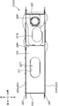
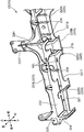
- FIG. 2 is a cross-sectional perspective view of the turning frame 22 of the crane 1 according to the present embodiment.
- 3 to 5 are a side view, a side sectional view, and a plan view of the revolving frame 22, respectively.
- the upper swing body 20 has a swing frame 22 (upper main body).
- the turning frame 22 constitutes a main body portion of the upper turning body 20 and is formed by welding a plurality of plate materials.
- the front-back direction (longitudinal direction of the turning frame 22) and the left-right direction (width direction of the turning frame 22) shown in each figure are directions based on the turning frame 22 (upper turning body 20).
- the revolving frame 22 includes a bottom wall 221, an upper wall 222, a pair of left and right side walls 223, a rear wall 224, a front wall 220, a plurality of inner walls 225, and a plurality of inner walls 225.
- An inner rib 226 and a central rib 22H are provided.
- the pair of left and right side walls 223 extend along the front-rear direction of the swivel frame 22 and are spaced apart from each other in the left-right direction of the swivel frame 22.
- the side wall 223 faces the left-right direction.
- the pair of left and right side walls 223 includes a left side wall 223L (FIG. 2) and a right side wall 223R (FIG. 3). In FIG. 2, only the left side wall 223L appears, but the right side wall 223R (FIG. 3) also has the same structure as the left side wall 223L.
- Each of the pair of left and right side walls 223 includes a central protrusion 223T and a weight mounting portion 22S (weight mounting portion).
- the central protruding portion 223T is a portion in which a substantially central portion in the front-rear direction of the side wall 223 protrudes upward.
- a mast (not shown) that supports the boom 31 so as to be raised and lowered is attached to the central projecting portion 223T.
- the weight mounting portion 22S is disposed at the rear end portion of the side wall 223 (the turning frame 22).
- the weight mounting portion 22S has a U-shape, and the counterweight 30 is detachably mounted on the pair of left and right weight mounting portions 22S.
- the counterweight 30 has an engaging portion (not shown) that can engage with the weight mounting portion 22S.
- the aforementioned cab 25 is disposed on the turning frame 22 in front of the weight mounting portion 22S.
- the bottom wall 221 is a plate material that defines the lower surface of the revolving frame 22.
- the bottom wall 221 is disposed so as to face the vertical direction between the pair of left and right side walls 223 and connects the pair of left and right side walls 223 in the left and right direction.
- the bottom wall 221 extends in the front-rear direction from the front end portion to the rear end portion of the side wall 223.
- a bottom wall front opening 221S and a bottom wall rear opening 221T are opened in the bottom wall 221 (FIG. 2).
- the bottom wall front opening portion 221S is an opening portion opened to the bottom wall 221 in front of the central projecting portion 223T.
- the bottom wall rear opening 221T is an opening that is opened in the bottom wall 221 behind the central protrusion 223T.
- the bottom wall front opening 221S and the bottom wall rear opening 221T are both opened in the shape of a long hole extending in the front-rear direction.
- the upper wall 222 is a plate material that defines the upper surface of the revolving frame 22.
- the upper wall 222 is disposed above the bottom wall 221 with a space therebetween.
- the upper wall 222 is disposed so as to face the vertical direction between the pair of left and right side walls 223 and connects the pair of left and right side walls 223 in the left and right direction.
- openings are formed in the upper wall 222 above the bottom wall front opening 221 ⁇ / b> S and the bottom wall rear opening 221 ⁇ / b> T, respectively.
- the rear wall 224 connects the rear end of the pair of left and right side walls 223, the rear end of the bottom wall 221 and the rear end of the upper wall 222.
- the rear wall 224 extends along the vertical direction.
- the front wall 220 connects the front end portions of the pair of left and right side walls 223, the front end portion of the bottom wall 221, and the front end portion of the upper wall 222.
- the bottom wall 221, the upper wall 222, the pair of side walls 223, the front wall 220 and the rear wall 224 form a box shape of the revolving frame 22. As shown in FIG. 2, an elliptical opening is formed in the rear wall 224.
- the plurality of inner walls 225 extend along the vertical direction between the pair of left and right side walls 223 and are spaced apart from each other in the front-rear direction. Both ends in the left-right direction of the plurality of inner walls 225 are connected to a pair of left and right side walls 223, respectively. In addition, lower end portions and upper end portions of the plurality of inner walls 225 are connected to the bottom wall 221 and the upper wall 222, respectively. An elliptical opening is formed in the plurality of inner walls 225.
- the plurality of inner walls 225 include a first inner wall 225A, a second inner wall 225B, a third inner wall 225C, and a fourth inner wall 225D.
- the first inner wall 225A is disposed near the front end of the bottom wall front opening 221S
- the second inner wall 225B is disposed near the rear end of the bottom wall front opening 221S.
- the third inner wall 225C is disposed behind the second inner wall 225B and in the vicinity of the front end portion of the bottom wall rear opening 221T.
- the fourth inner wall 225D is disposed in the vicinity of the rear end portion of the bottom wall rear opening 221T.
- the rear wall 224, the third inner wall 225C, and the fourth inner wall 225D constitute a plurality of vertical plates of the present invention.
- the 3rd inner wall 225C comprises one vertical board of the present invention.
- the third inner wall 225C is disposed at a position closest to the turning bearing 21 (first ring portion 21A) among the plurality of vertical plates.
- the plurality of inner ribs 226 are fixed to the inner surface of the side wall 223, and are disposed so as to connect the bottom wall 221 and the upper wall 222 along the vertical direction.
- the plurality of inner walls 225 and the plurality of inner ribs 226 ensure the rigidity of the turning frame 22.
- the central rib 22H is disposed inside the central protrusion 223T and prevents the central protrusion 223T from falling down.
- FIG. 6 is an enlarged bottom view of the turning frame 22 of the crane 1 according to the present embodiment, and is an enlarged view of the periphery of the bearing mounting portion 21S.
- FIG. 7 is a cross-sectional view of the upper revolving structure 20 (the revolving frame 22) and the lower traveling structure 10 around the bearing mounting portion 21S.
- the slewing bearing 21 has a circular first ring portion 21A and a circular second ring portion 21B (FIG. 7).
- the first ring portion 21 ⁇ / b> A is fixed to a bearing mounting portion 21 ⁇ / b> S formed on the bottom wall 221 of the turning frame 22.
- the second ring portion 21B is disposed on the radially inner side of the first ring portion 21A and is fixed to a bearing mounting portion 110S (FIG. 7) formed on the upper surface portion 110 (FIG. 7) of the lower traveling body 10.
- the first ring portion 21A is rotatable relative to the second ring portion 21B around the pivot axis CL.
- a plurality of gear teeth 21C are formed along the circumferential direction on the inner peripheral surface of the second ring portion 21B.
- the crane 1 has the turning motor M (FIG. 7) fixed to the turning motor mounting part 22M of the bottom wall 221.
- the pinion gear MP of the turning motor M is engaged with the gear teeth 21C of the second ring portion 21B.
- the turning frame 20 further includes a pair of left and right measurement abutments 50 (deformable members).
- the crane 1 also includes a pair of left and right strain gauges 51 (deformation amount detection unit).
- FIG. 8 is an enlarged cross-sectional perspective view of the periphery of the measurement support 50 shown in FIG.
- FIG. 9 is a schematic cross-sectional view in which the periphery of the measurement support 50 is enlarged.
- FIG. 8 only the left measurement abutment 50 and the strain gauge 51 among the pair of left and right measurement abutments 50 and the strain gauge 51 appear, but the right measurement abutment 50 and the strain gauge 51 are shown in FIG.
- Nine measurement abutments 50 and strain gauges 51 are arranged at positions spaced to the right.
- the structure of the revolving frame 22 is arranged symmetrically about a center line (not shown) that extends in the front-rear direction through the center of the revolving frame 22 in the left-right direction.
- the measurement abutment 50 is disposed in the revolving frame 22 at a position behind the first ring portion 21A and in front of the weight mounting portion 22S and closer to the first ring portion 21A than the weight mounting portion 22S. ing.
- the measurement abutment 50 is disposed at a corner formed by the bottom wall 221 and the third inner wall 225C.
- the measurement support 50 receives a force from members around the turning frame 22 and deforms together with these members.
- the strain gauge 51 is attached to the measurement abutment 50, and outputs a signal corresponding to the strain amount (deformation amount) of the measurement abutment 50 (swivel frame 22) when the counterweight 30 is attached (detects the deformation amount). .
- the aforementioned third inner wall 225 ⁇ / b> C has a rear surface portion 225 ⁇ / b> C ⁇ b> 1 facing in the rear direction of the turning frame 22.
- the bottom wall 221 has an upper surface portion 221A facing upward.
- the upper surface portion 221A and the rear surface portion 225C1 are connected to each other to form a corner portion to which the measurement support 50 is fixed.
- the measurement abutment 50 is made of a plate material extending in the vertical direction and the front-rear direction. That is, the dimension of the measurement support 50 in the left-right direction is set to be smaller than the dimensions of the measurement support 50 in the front-rear direction and the vertical direction.
- the measurement support 50 has a first surface 50A, a second surface 50B, and a holding surface 50C.
- the first surface 50A is a front surface portion of the measurement support 50, and is connected to the rear surface portion 225C1 (FIG. 9) of the third inner wall 225C along the vertical direction.
- the second surface 50B is a lower surface portion of the measurement abutment 50, and is connected to the upper surface portion 221A (FIG.
- the holding surface 50C connects the first surface 50A and the second surface 50B, and holds the strain gauge 51.
- the holding surface 50 ⁇ / b> C has an inclined surface that inclines upward toward the front of the revolving frame 22 and holds the strain gauge 51. As shown in FIG. 9, in the present embodiment, the inclined surface is an arcuate curved surface.
- the strain gauge 51 receives the signal according to the expansion and contraction (arrow D2 in FIG. 9) of the holding surface 50C on a reference plane (a plane parallel to the paper in FIG. 9) including the front-rear direction and the vertical direction. Is held on the holding surface 50C. That is, the strain gauge 51 outputs a signal corresponding to the strain amount of the portion of the revolving frame 20 where the strain gauge 51 is mounted.
- the strain gauge 51 is detachably fixed to the holding surface 50C.
- the left side wall 223L is arranged to face the strain gauge 51 in the left-right direction. Further, the upper wall 222 (upper plate) is disposed so as to cover the strain gauge 51 from above.
- the crane 1 further includes a control unit 60.
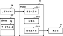
- FIG. 10 is a block diagram of the control unit 60 of the crane 1 according to the present embodiment.
- the control unit 60 includes a CPU (Central Processing Unit), a ROM (Read Only Memory) that stores a control program, a RAM (Random Access Memory) used as a work area of the CPU, and the like. Further, in addition to the strain gauge 51 described above, a display unit 61 (notification unit) and an operation unit 62 (information input unit) are electrically connected to the control unit 60.
- a display unit 61 notification unit
- an operation unit 62 information input unit
- the display unit 61 is a liquid crystal panel arranged in front of the driver's seat in the cab 25, and notifies the operator of work information of the crane 1 and the like.
- the display unit 61 receives information based on a signal output from the strain gauge 51, and notifies an operator in the cab 25 that the counterweight 30 is mounted on the weight mounting unit 22S.
- the above information may be notified by a speaker that generates a buzzer sound, a lamp that emits light, or the like.
- the operation unit 62 is provided in the cab 25 and is operated by an operator.
- the operation unit 62 includes an operation lever (not shown) for operating the crane 1 and a mode switch 621.
- the mode switch 621 is also operated by an operator. In this embodiment, when the “automatic detection mode” for detecting whether or not the counterweight 30 is mounted on the weight mounting portion 22S is started.
- the mode switch 621 is pressed by the operator. When the mode switch 621 is pressed, a predetermined command signal is input to the control unit 60.
- the control unit 60 detects that the counterweight 30 is mounted on the weight mounting unit 22S based on the signal output from the strain gauge 51.
- the control unit 60 includes a mounting determination unit 601, a storage unit 602, and an information output unit 603 (warning information output unit, erroneous loading information output unit) by the CPU executing a control program stored in the ROM. Function.
- the mounting determination unit 601 receives a signal output from the strain gauge 51 and determines whether or not the counterweight 30 is mounted on the weight mounting unit 22S according to the magnitude of the signal.
- the storage unit 602 stores and outputs a threshold value corresponding to the weight of the counterweight 30 in advance.
- the mounting determination unit 601 compares the strain amount detected by the strain gauge 51 with the threshold value output from the storage unit 602 to determine whether or not the counterweight 30 is mounted on the weight mounting unit 22S. Determine.
- the information output unit 603 When the mounting determination unit 601 determines that the counterweight 30 is mounted on the weight mounting unit 22S, the information output unit 603 outputs “counterweight mounting completion information” to the display unit 61, and the information is output. It is displayed on the display unit 61. Further, as described later, the information output unit 603 outputs “warning information” when the counterweight 30 having a weight different from the set counterweight 30 is mounted on the weight mounting unit 22S, and is displayed on the display unit 61. Display.
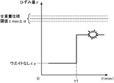
- FIG. 11 is a graph showing the transition of the strain amount when the counterweight 30 is mounted in the crane 1 according to this embodiment.
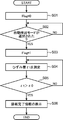
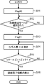
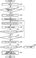
- FIG. 12 is a flowchart showing how the crane 1 detects the mounting of the counterweight 30.
- the counterweight 30 is integrally configured by previously laminating a plurality of weight bodies 300 on the ground in the assembly stage of the crane 1. Thereafter, the counterweight 30 (a plurality of weight bodies 300) is mounted on the weight mounting portion 22S (FIG. 2) by an auxiliary crane (not shown) as indicated by the arrow in FIG.
- step S01 when the assembly operation of crane 1 is started, mounting determination unit 601 of control unit 60 resets Flag stored in storage unit 602 to 0 (zero) (step S01).
- step S02 when the operator presses the mode switch 621 of the operation unit 62, the automatic detection mode of the counterweight 30 is selected (YES in step S02).
- the attachment determination unit 601 repeats step S02 until the mode switch 621 is pressed (NO in step S02).
- step S03 the mounting determination part 601 measures the distortion amount (epsilon) t of the measurement support 50 by receiving the signal output from the strain gauge 51 (step S04).
- the measurement of the strain amount ⁇ t is continuously executed at predetermined time intervals. During this time, the mounting determination unit 601 compares the magnitude relationship between the strain amount ⁇ t and the threshold value ⁇ 0 set in advance according to the weight of the counterweight 30 (step S05).
- Table 1 shows information stored in the storage unit 602 in the present embodiment.
- the weight of the counterweight 30 is 100 t.
- the threshold ⁇ 0 is set to 60%. .
- step S05 when ⁇ t> ⁇ 0 (YES in step S05), that is, when the strain amount ⁇ t detected by the strain gauge 51 exceeds the threshold value ⁇ 0, the mounting determination unit 601 determines that the counterweight 30 is the weight mounting unit 22S. It is determined that it is attached to. Then, the information output unit 603 outputs “counterweight mounting completion information” to the display unit 61, and displays the information on the display unit 61 (step S06).
- the strain amount ⁇ t detected by the strain gauge 51 increases from ⁇ p in the no-weight state and exceeds the threshold value ⁇ 0.
- the mounting determination unit 601 can determine that the counterweight 30 is mounted on the weight mounting unit 22S.
- step S05 if ⁇ t ⁇ ⁇ 0 (NO in step S05), steps S04 and S05 are repeated.
- the strain gauge 51 when the counterweight 30 is mounted on the weight mounting portion 22S, the strain gauge 51 outputs a signal corresponding to the deformation amount of the measurement support 50 on the turning frame 22.
- the control unit 60 receives the signal output from the strain gauge 51 and detects that the counterweight 30 is mounted on the weight mounting unit 22S. For this reason, the mounting of the counterweight 30 can be detected based on the deformation of the front portion of the turning frame 22 relative to the weight mounting portion 22S.
- the measurement support 50 is arranged in front of the weight mounting portion 22S, particularly at a position closer to the turning bearing 21 (first ring portion 21A) than the weight mounting portion 22S.
- the crane 1 which can detect the mounting state of the counterweight 30 stably can be provided. Further, as compared with a technique in which the mounting state of the counterweight 30 is detected according to the information of the RFID tag mounted on the counterweight 30, erroneous detection due to tag damage or detachment is prevented.
- the mounting determination unit 601 compares the strain amount ⁇ t detected by the strain gauge 51 with the threshold value ⁇ 0 output from the storage unit 602, so that the counterweight 30 has the weight. It is determined whether or not the mounting portion 22S is mounted. For this reason, the mounting of the counterweight 30 can be detected according to the change in the strain amount ⁇ t detected by the strain gauge 51. Furthermore, it is possible to quickly determine whether the counterweight 30 is mounted in response to the detected strain amount ⁇ t exceeding the threshold value ⁇ 0.
- the first ring portion 21A of the swing bearing 21 functions as a fixed end
- the periphery of the weight mounting portion 22S functions as a free end that can move up and down. Therefore, when the counterweight 30 is mounted on the weight mounting portion 22S, a load is applied downward on the bottom wall 221 to which the second surface 50B of the measurement support 50 is connected, as indicated by an arrow D1 in FIG. Is granted.
- the first surface 50A of the measurement support 50 is connected to the third inner wall 225C, it is difficult to move in the front-rear direction.
- a tensile stress as indicated by an arrow D2 is generated on the holding surface 50C that holds the strain gauge 51.
- the strain gauge 51 inputs a signal (voltage) corresponding to the deformation amount of the holding surface 50 ⁇ / b> C to the mounting determination unit 601 (FIG. 10) of the control unit 60. Then, as described above, when the signal (strain amount ⁇ t) exceeds a preset threshold value ⁇ 0, the mounting determination unit 601 determines that the counterweight 30 is mounted on the weight mounting unit 22S, and the information is The information is output from the information output unit 603 and displayed on the display unit 61. For this reason, it is possible for the operator who is riding on the cab 25 facing forward to recognize that the counterweight 30 is mounted on the weight mounting portion 22S behind the cab 25.
- the strain gauge 51 detects that the weight of the counterweight 30 is applied to the rear end of the swivel frame 22 as the amount of deformation of the holding surface 50C of the measurement support 50. For this reason, the mounting state of the counterweight 30 can be detected easily and at a low cost without providing a load meter corresponding to the large weight of the counterweight 30.
- the measurement abutment 50 includes a first surface 50A connected to the third inner wall 225C, a second surface 50B connected to the bottom wall 221, and a first surface. 50A and the 2nd surface 50B are connected, and it has the holding surface 50C holding the strain gauge 51.
- the strain gauge 51 is held by the holding surface 50C so as to output the signal according to the expansion and contraction of the holding surface 50C on the reference plane including the front-rear direction and the vertical direction. For this reason, when a load corresponding to the weight of the counterweight 30 is applied to the weight mounting portion 22S, a large stress is generated on the holding surface 50C, and the strain gauge 51 increases the amount of deformation of the holding surface 50C according to the stress.
- the measurement support 50 when the measurement support 50 is provided, the arrangement, shape, and material of the measurement support 50 are adjusted and the deformation of the measurement support 50 is compared with the case where the strain gauge 51 is directly attached to the revolving frame 22. By increasing the amount, it can be accurately determined that the counterweight 30 is mounted.
- the measurement support 50 (strain gauge 51) is a third vertical plate located behind the slewing bearing 21 and positioned closest to the slewing bearing 21 (first ring portion 21A). It is attached to the inner wall 225C.
- the periphery of the first ring portion 21A of the turning frame 22 functions as a fixed end
- the periphery of the weight mounting portion 22S functions as a free end.
- the third inner wall 225C to which the measurement abutment 50 is attached is disposed at a position close to the fixed end. Therefore, a large downward force is applied to the second surface 50B of the measurement support 50 (arrow D1 in FIG. 9), and the deformation amount of the holding surface 50C can be set large. For this reason, the strain gauge 51 can stably detect the deformation amount of the holding surface 50C.
- a pair of left and right side walls 223 are disposed on both sides of the measurement support 50 (strain gauge 51) in the left-right direction, and an upper wall 222 is disposed above the measurement support 50. For this reason, the deformation detection operation of the strain gauge 51 is not easily influenced by the environment outside the crane 1 such as rain and wind. Further, it is possible to prevent an object from colliding with the strain gauge 51 and damaging the strain gauge 51.
- the dimension in the left-right direction of the measurement support 50 is set smaller than the dimensions of the measurement support 50 in the front-rear direction and the vertical direction. That is, the measurement abutment 50 is a plate material extending along the front-rear direction and the vertical direction, and the holding surface 50C corresponds to a thickness portion of the plate material. In this case, since the deformation of the holding surface 50C in the left-right direction is small, the strain gauge 51 can accurately detect the deformation amount of the holding surface 50C along the arrow D2 direction in FIG.
- the strain gauge 51 is detachable from the holding surface 50C.
- the strain gauge 51 is fixed to the holding surface 50C with an adhesive.
- the strain gauge 51 can be peeled off from the holding surface 50C by using another solvent that dissolves the adhesive. For this reason, even when the assembly work of the crane 1, in other words, the attachment / detachment work of the counterweight 30 is repeated, even when the sensitivity of the strain gauge 51 is lowered, the strain gauge 51 can be easily replaced.
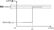
- FIG. 13 is a graph showing the transition of the strain amount when the counterweight 30 is mounted in the crane 1 according to this embodiment.
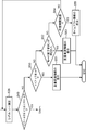
- FIG. 14 is a flowchart showing a state in which mounting of the counterweight 30 is detected in the crane 1 according to the present embodiment.
- mounting determination unit 601 of control unit 60 resets Flag stored in storage unit 602 to 0 (zero) (step S11).
- the automatic detection mode of the counterweight 30 is selected (YES in step S12).
- the mounting determination unit 601 repeats step S12 until the mode switch 621 is pressed (NO in step S12).
- the mounting determination unit 601 updates the flag stored in the storage unit 602 to 1 (step S13).
- the attachment determination part 601 measures the distortion amount (epsilon) t of the measurement support 50 by receiving the signal output from the strain gauge 51 (step S14).
- the measurement of the strain amount ⁇ t is continuously executed at predetermined time intervals.
- the attachment determination unit 601 compares the magnitude relationship between the strain amount ⁇ t and the threshold value ⁇ 0 set in advance according to the weight of the counterweight 30 (step S15).
- the error ⁇ is set to the threshold value ⁇ 0 in consideration of the variation in weight associated with the manufacturing error of the counterweight 30. That is, the threshold value ⁇ 0 ⁇ ⁇ corresponds to the weight of the counterweight 30.
- ⁇ is set to ⁇ 10% with respect to a strain amount of 100% corresponding to the weight 100 t of the counterweight 30.
- the mounting determination unit 601 It is determined that the counterweight 30 is attached to the weight attachment portion 22S. Then, the information output unit 603 outputs “counterweight mounting completion information” to the display unit 61, and displays the information on the display unit 61 (step S16).
- the strain amount ⁇ t detected by the strain gauge 51 increases from ⁇ p and falls within the range of the threshold value ⁇ 0 ⁇ ⁇ .
- step S15 if ⁇ p ⁇ t ⁇ 0- ⁇ or ⁇ 0 + ⁇ ⁇ t (NO in step S15), steps S14 and S15 are repeated.
- the threshold value set according to the weight of the counterweight 30 includes a preset lower limit value ( ⁇ 0 ⁇ ) and an upper limit value ( ⁇ 0 + ⁇ ). Then, when the strain amount ⁇ t detected by the strain gauge 51 is included between the lower limit value and the upper limit value, the attachment determination unit 601 determines that the counterweight 30 is attached to the weight attachment unit 22S. For this reason, even when the weight of the counterweight 30 varies due to manufacturing errors, it is possible to stably detect that the counterweight 30 is mounted on the weight mounting portion 22S, and to prevent erroneous detection.
- the information output unit 603 may output predetermined warning information (error information). In this case, when the weight of the mounted counterweight 30 exceeds a predetermined error range, warning information can be output promptly.
- FIGS. 15 to 17 are graphs showing changes in the strain amount when the counterweight 30 is mounted in the crane 1 according to this embodiment.
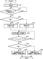
- FIG. 18 is a flowchart showing a state in which mounting of the counterweight 30 is detected in the crane 1 according to the present embodiment.
- step S21 when the assembly work of crane 1 is started, mounting determination unit 601 of control unit 60 resets Flag stored in storage unit 602 to 0 (zero) (step S21).
- step S21 when the operator presses the mode switch 621 of the operation unit 62, the automatic detection mode of the counterweight 30 is selected (YES in step S22). Also in this embodiment, the mounting determination unit 601 repeats step S22 until the mode switch 621 is pressed (NO in step S22).
- the mode switch 621 can select a mode from two mode menus. One mode is a full weight specification mode (maximum mounting mode), and the other mode is a lightweight specification mode (partial mounting mode).
- the mounting determination unit 601 updates the flag in the storage unit 602 to 1, and when the worker selects the lightweight specification mode, the mounting determination unit 601 sets the flag in the storage unit 602 to 2. Update. If the updated flag is 1 (YES in step S23), the attachment determination unit 601 selects ⁇ max as the threshold value ⁇ 0 stored in the storage unit 602 (step S24). On the other hand, if the updated Flag is not 1 (NO in step S23), the attachment determination unit 601 selects ⁇ a as the threshold value ⁇ 0 stored in the storage unit 602 (step S25).
- the threshold value ⁇ max is a threshold value corresponding to the total weight of all the weight bodies 300 among the plurality of weight bodies 300.
- the threshold value ⁇ a is the threshold value corresponding to the total weight of some weight bodies 300 used in the lightweight specification mode among the plurality of weight bodies 300. At this time, the weight body 300 used in the lightweight specification mode is determined in advance. Table 2 shows information stored in the storage unit 602 in the present embodiment.
- the weight of the counterweight 30 is 100 t, and the strain amount threshold value ⁇ 0 (threshold value ⁇ max) detected by the strain gauge 51 is set to 100%.
- the weight of the counterweight 30 is 80 t, and the strain amount threshold value ⁇ 0 (threshold value ⁇ a) detected by the strain gauge 51 is set to 80%.
- ⁇ is set to 10%
- ⁇ is set to 8%.
- the attachment determination unit 601 receives the signal output from the strain gauge 51 to measure the strain amount ⁇ t of the measurement support 50 (step S26). Then, the attachment determination unit 601 compares the magnitude relationship between the strain amount ⁇ t and the threshold value ⁇ 0 set in advance according to the weight of the counterweight 30 (step S27). Also in this embodiment, the error ⁇ is set to the threshold value ⁇ 0 as in the second embodiment.
- the mounting determination unit 601 determines that the counterweight 30 is attached to the weight attachment portion 22S. Further, the mounting determination unit 601 confirms the value of Flag (step S28), and when the flag is 1 (YES in step S28), the information output unit 603 displays “Counterweight mounting complete in full weight specification mode” "Information” is output to the display unit 61, and the information is displayed on the display unit 61 (step S29).
- Step S28 the information output unit 603 outputs “counterweight loading completion information in the lightweight specification mode” to the display unit 61, and the information is displayed. It is displayed on the display unit 61 (step S30).
- the strain amount ⁇ t detected by the strain gauge 51 at time t1 increases from ⁇ p in the no-weight state and is included in the range of the threshold ⁇ max ⁇ ⁇ .
- “Counterweight loading completion information” is displayed on the display unit 61.
- the mounting determination unit 601 can detect that the counterweight 30 is mounted on the weight mounting unit 22S. In this embodiment, if ⁇ t ⁇ 0 ⁇ or ⁇ 0 + ⁇ ⁇ t in step S27 (NO in step S27), steps S26 and S27 are repeated.
- the mode switch 621 of the operation unit 62 receives mode information related to the number of weight bodies 300 mounted on the weight mounting unit 22S.
- the mode switch 621 can selectively accept at least the full weight specification mode and the light weight specification mode. In the full weight specification mode, all the weight bodies 300 of the plurality of weight bodies 300 are attached to the weight mounting portion 22S. In the lightweight specification mode, a part of the plurality of weight bodies 300 is mounted on the weight mounting portion 22S.
- the attachment determination unit 601 compares the strain amount ⁇ t detected by the strain gauge 51 with the full weight threshold value ⁇ max output from the storage unit 602. Then, it is determined whether or not all the weight bodies 300 are mounted on the weight mounting portion 22S.
- the wearing determination unit 601 compares the strain amount ⁇ t detected by the strain gauge 51 with the partial weight threshold value ⁇ a output from the storage unit 602. It is determined whether or not the partial weight body 300 is mounted on the weight mounting portion 22S. Therefore, whether or not the full weight specification mode or the light weight specification mode is selected in the crane 1, an appropriate threshold value regarding the weight of the weight body 300 is adopted, and whether or not the weight body 300 is attached. Can be determined.
- the information output unit 603 may output predetermined warning information (error information). Also in this case, if the weight of the mounted counterweight 30 exceeds a predetermined error range, warning information can be output promptly.
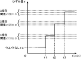
- FIG. 19 is a graph showing the transition of the strain amount when the counterweight 30 is mounted in the crane 1 according to this embodiment.
- FIG. 20 is a flowchart showing a state in which mounting of the counterweight 30 is detected in the crane 1 according to the present embodiment.
- the weight bodies 300 are stacked one by one on the weight mounting portion 22S.
- the number of weight bodies 300 to be mounted on the weight mounting unit 22S (the number N of stages, the planned number of stacks) is set in advance, and the operator inputs the number N of stages from the operation unit 62.
- step S31 when the assembly operation of crane 1 is started, mounting determination unit 601 of control unit 60 resets Flag stored in storage unit 602 to 0 (zero) (step S31).
- step S32 when the operator presses the mode switch 621 of the operation unit 62, the automatic detection mode of the counterweight 30 is selected (YES in step S32). Also in this embodiment, the mounting determination unit 601 repeats step S32 until the mode switch 621 is pressed (NO in step S32).
- the attachment determination unit 601 updates the variable n, the threshold value ⁇ 0, and the error variable ⁇ 0 that are stored in the storage unit 602, respectively, to 0 (step S33).
- the number N (maximum number) of the weight bodies 300 is input by the operator through the operation unit 62 (step S34).
- the number N of steps corresponds to information on the number of weight bodies 300 that are scheduled to be mounted on the weight mounting portion 22S.
- Table 3 shows information stored in the storage unit 602 in the present embodiment.
- the stage number N is set to be selectable up to 9, and the weight of each weight body 300 is set in the range of 8t to 15t.
- the strain amount ⁇ t of the strain gauge 51 with respect to the total weight is 100%
- the strain amount of the strain gauge 51 with respect to each weight body 300 ⁇ 0 is set in the range of 8% to 15%.
- Table 3 shows the accumulated strain amount of the strain gauge 51 when the weight bodies 300 are stacked in order from the first stage.
- the information is also stored in the storage unit 602. In either case, ⁇ is set to ⁇ 1%.
- the step number N input by the operator in step S34 is stored in the storage unit 602 as Nmax.
- ⁇ (n) and ⁇ (n) are both a threshold value (distortion amount) and an error set in advance corresponding to the n-th weight body 300.
- information regarding the threshold value and error is stored in advance in the storage unit 602 together with information regarding the order in which the weight bodies 300 are stacked.
- the attachment determination unit 601 receives the signal output from the strain gauge 51 to measure the strain amount ⁇ t of the measurement support 50 (step S36).
- the measurement of the strain amount ⁇ t is continuously executed at predetermined time intervals.
- the mounting determination unit 601 compares the magnitude relationship between the strain amount ⁇ t and the threshold value ⁇ 0 set in advance according to the weight of the counterweight 30 (step S37).
- the mounting determination unit 601 It is determined that the n-th weight body 300 is mounted on the weight mounting portion 22S.
- the mounting determination unit 601 determines whether n is equal to the maximum number of steps Nmax stored in the storage unit 602 (step S38).
- n Nmax (YES in step S38)
- the attachment determination unit 601 updates the threshold value ⁇ 0 and the error variable ⁇ 0 to ⁇ max and ⁇ max, respectively (step S39).
- the threshold value ⁇ max and the error ⁇ max are a threshold value (strain amount) and an error corresponding to the total weight of all the weight bodies 300, and are stored in the storage unit 602 in advance.
- the storage unit 602 compares the magnitude of the strain amount ⁇ t detected by the strain gauge 51 with a threshold value ⁇ 0 ( ⁇ max) set in advance according to the total weight of the counterweight 30 (step S40).
- the strain amount ⁇ t with respect to the total weight of all the loaded weight bodies 300 is evaluated.
- the mounting determination unit 601 It is determined that all scheduled weight bodies 300 are properly mounted on the weight mounting portion 22S.
- the information output unit 603 outputs “counterweight loading completion information in the full weight specification mode” to the display unit 61, and displays the information on the display unit 61 (step S41).
- FIG. 19 shows a state in which the weights 300 from the first stage to the third stage are sequentially stacked on the weight mounting portion 22S after the number of stages N (Nmax) is set to 3 by the operator. . That is, at time t1, the strain amount ⁇ t detected by the strain gauge 51 increases from ⁇ p and is included in the range of threshold ⁇ (1) ⁇ ⁇ . By the change in the strain amount ⁇ t, the attachment determination unit 601 can determine that the first-stage weight body 300 is attached to the weight attachment unit 22S. Similarly, at times t2 and t3, the strain amount ⁇ t is included in the range of the threshold value ⁇ (2) ⁇ ⁇ and the threshold value ⁇ (3) ⁇ ⁇ .
- the attachment determination unit 601 can determine that the second-stage and third-stage weight bodies 300 are attached to the weight attachment part 22S.
- the mounting determination unit 601 can store in the storage unit 602 how many weight bodies 300 are stacked on the weight mounting unit 22S.
- the information output unit 603 causes the display unit 61 to display the information on the number of stacked sheets, so that the operator can be notified of the information.
- step S40 when ⁇ p ⁇ t ⁇ 0 ⁇ 0 or ⁇ 0 + ⁇ 0 ⁇ t in step S40 (NO in step S40), the attachment determination unit 601 executes predetermined error processing (step S42). .
- FIG. 21 is a flowchart showing error processing when the mounting of the counterweight 30 is detected in the crane 1 according to the present embodiment.
- mounting determination unit 601 determines whether ⁇ t> ⁇ 0 + ⁇ 0 in step S50. Determine whether or not. If ⁇ t> ⁇ 0 + ⁇ 0 (YES in step S50), the weight of the counterweight 30 loaded exceeds the preset threshold value as shown in FIG.
- the “overweight information” (warning information) is output, and the information is displayed on the display unit 61.
- the mounting determination unit 601 checks the output of the mode switch 621 and determines whether or not the end button of the automatic detection mode has been pressed by the operator (step S52).
- the information output unit 603 outputs “weight not reached information” (warning information) to the display unit 61. The information is displayed (step S53).
- the attachment determination unit 601 determines whether a predetermined time has elapsed (step S54).
- the predetermined time has elapsed (YES in step S54)
- the weight of the loaded counterweight 30 has not reached the predetermined threshold value, and the operator is on standby waiting for the loading work to be completed. Equivalent to. Therefore, the information output unit 603 outputs “timeout information” to the display unit 61, and displays the information on the display unit 61 (step S55). In this case, by recognizing that the weight of the counterweight 30 has been left for a predetermined time in a state where the weight of the counterweight 30 has not been reached, it is possible to check the cause of the work restart or the error.
- step S51, S53, and S55 the attachment determination unit 601 ends the automatic detection mode. If the predetermined time has not elapsed in step S54 (NO in step S54), the attachment determination unit 601 repeats step S36 and subsequent steps.
- the storage unit 602 loads the weight unit threshold value ⁇ (n) corresponding to the weight of each weight body 300 out of the plurality of weight bodies 300 and each weight body 300.
- the order in which they are performed is stored.
- the attachment determination unit 601 detects the weight body 300 loaded on the nth (n is a natural number) by the strain gauge 51 from the state in which the (n ⁇ 1) th weight body 300 is loaded. By comparing the increment (change amount) of the strain amount ⁇ t with the weight single unit threshold value ⁇ (n) of the nth weight body 300 output from the storage unit 602, each weight body 300 has the weight mounting portion 22S. It is determined whether or not it is attached to the camera.
- the attachment determination unit 601 compares the strain amount ⁇ t detected by the strain gauge 51 with the sum (cumulative value) of the first to nth threshold values for the single weight output from the storage unit 602. Thus, it may be determined whether or not each weight body 300 is mounted on the weight mounting portion 22S. According to such a configuration, it is possible to accurately determine that each weight body 300 is mounted on the weight mounting portion 22S individually.
- the attachment determination unit 601 compares the amount of change in the strain amount ⁇ t detected by the strain gauge 51 with the weight single unit threshold value output from the storage unit 602 or the strain detected by the strain gauge 51. By comparing the amount ⁇ t and the sum of the plurality of weight single unit threshold values output from the storage unit 602, it is determined whether or not each weight body 300 is mounted on the weight mounting unit 22S.
- the information output unit 603 may output predetermined erroneous loading information. In this case, when a weight body 300 different from the nth weight body 300 to be mounted is mounted, erroneous loading information can be output promptly.
- the method of detecting the counterweight 30 of the crane 1 according to the present embodiment is such that the swivel frame 22 is attached to the front portion of the swivel frame 22 with respect to the weight mounting portion 22S.
- the mounting of the counterweight 30 can be detected based on the deformation of the swivel frame 22 in front of the weight mounting portion 22S. Further, when the counterweight 30 is mounted, a direct impact corresponding to the weight of the counterweight 30 is not applied to the strain gauge 51.
- each characteristic of the crane 1 in said embodiment is also contained in the said detection method.
- the strain gauge 51 is used as the deformation amount detection unit.
- the deformation amount detection unit is a sensor other than the strain gauge 51, such as a semiconductor strain gauge, an optical fiber, or a load cell. Also good.
- the measurement abutment 50 is described as being fixed to the third inner wall 225C, the bottom wall 221, the upper wall 222, and a pair of left and right are positioned closer to the first ring portion 21A than the weight mounting portion 22S. It may be fixed to the side wall 223, the second inner wall 225B, the third inner wall 225, or the like.
- the strain gauge 51 is directly attached to the bottom wall 221, the upper wall 222, the pair of left and right side walls 223, the second inner wall 225 ⁇ / b> B, the third inner wall 225, and the like without being attached to the measurement support 50. Attached).
- the arrangement, shape, and material of the measurement support 50 can be adjusted to increase the amount of deformation of the measurement support 50. It is possible to determine with higher accuracy that the counterweight 30 is mounted than when the strain gauge 51 is directly mounted on the revolving frame 22.
- the number of the measurement abutments 50 and the strain gauges 51 is not limited to two (a pair of left and right), and one or three or more measurement abutments 50 and the strain gauges 51 may be arranged.
- FIG. 22 is a cross-sectional perspective view of the revolving frame 22 according to the first modified embodiment of the present invention.
- a pair of upper and lower strain gauges 50 ⁇ / b> L are directly attached to the bottom wall 221 and the upper wall 222.
- transformation amount detection part (strain gauge) which concerns on this invention may be the aspect with which it mounts
- FIG. 23 and FIG. 24 are enlarged perspective sectional views of the measurement supports 50M and 50N according to the second and third modified embodiments of the present invention, respectively.
- the holding surface 50C of the measurement abutment 50 has been described as being a curved surface.
- the holding surface 50C may be an inclined plane.
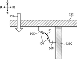
- FIG. 25 is an enlarged cross-sectional view of the measurement support 50P according to the fourth modified embodiment of the present invention.
- the measurement support 50P is disposed at a corner where the upper end of the third inner wall 225C and the upper wall 222 intersect.
- a force is applied to the upper wall 222 along the direction of arrow D3 in FIG.
- a compressive stress as indicated by an arrow D4 is generated on the holding surface 50C of the measurement support 50P.
- the strain gauge 51 detects the amount of deformation of the holding surface 50C due to the compressive stress.
- the strain gauge 51 can accurately detect the deformation amount of the holding surface 50C along the direction of the arrow D4 in FIG.
- the work machine is an upper body having a weight mounting portion disposed at a rear end portion of the upper body
- the upper body includes: A lower body that supports the upper body so as to be pivotable about a pivot axis that extends in the vertical direction, and a cab that is disposed on the upper body in front of the weight mounting portion and allows an operator to board the cabin.
- a raising and lowering member that is detachably attached to a front portion of the upper body, a first ring portion that is fixed to the upper body, and a second ring portion that is fixed to the lower body.
- the ring portion is rotatable relative to the second ring portion around the pivot axis, a swing bearing, a counterweight detachably mounted on the weight mounting portion of the upper body, and the upper book
- a deformation amount detection unit that is mounted in a front portion of the weight mounting unit and detects a deformation amount of the upper body when the counterweight is mounted on the weight mounting unit, and is detected by the deformation amount detection unit.
- a mounting determination unit that determines that the counterweight is mounted on the weight mounting unit based on the deformation amount.
- the deformation amount detection unit detects the deformation amount of the upper body.
- the mounting determination unit determines that the counterweight is mounted on the weight mounting unit based on the deformation amount detected by the deformation amount detection unit. For this reason, the mounting of the counterweight can be detected based on the deformation of the front portion of the upper body relative to the weight mounting portion. Further, according to the above configuration, when the counterweight is mounted on the weight mounting portion, a direct impact corresponding to the weight of the counterweight is not applied to the deformation amount detection portion. Therefore, even when the assembly work of the work machine is repeatedly performed, the deformation amount detection unit is prevented from being damaged.
- the deformation amount detection unit is arranged in the weight mounting unit, it is possible to prevent the electrical wiring extending from the deformation amount detection unit from being damaged by coming into contact with the counterweight. In this way, it is possible to provide a work machine capable of stably detecting the mounting state of the counterweight. Furthermore, compared with a technique in which the mounting state of the counterweight is detected according to the information of the RFID tag mounted on the counterweight, erroneous detection due to tag damage or detachment is prevented.
- the deformation amount detection unit includes a strain gauge, and the strain gauge detects a strain amount of a portion of the upper body where the strain gauge is mounted as the deformation amount.
- the mounting state of the counterweight can be detected easily and at a low cost without providing a load meter corresponding to the large weight of the counterweight.
- the above configuration further includes a storage unit that stores and outputs a threshold value corresponding to the weight of the counterweight in advance, and the mounting determination unit outputs the strain amount detected by the strain gauge and the storage unit. It is desirable to determine whether or not the counterweight is mounted on the weight mounting portion by comparing the threshold value.
- the mounting determination unit determines that the counter weight is mounted on the weight mounting unit when the strain amount detected by the strain gauge exceeds the threshold value.
- the threshold value includes a lower limit value and an upper limit value that are set in advance according to the weight of the counterweight, and the mounting determination unit determines that the strain amount detected by the strain gauge is equal to the lower limit value.
- the mounting determination unit determines that the strain amount detected by the strain gauge is equal to the lower limit value.
- a warning information output unit that outputs predetermined warning information when the amount of strain detected by the strain gauge is smaller than the lower limit value or larger than the upper limit value.
- the counterweight has a plurality of weight bodies that can be stacked in the vertical direction on the weight mounting portion, and a mode relating to the number of the weight bodies mounted on the weight mounting portion.
- An information input unit for receiving information wherein the information input unit is capable of selectively receiving at least a maximum mounting mode and a partial mounting mode, and in the maximum mounting mode, all weight bodies among the plurality of weight bodies.
- an information input unit is further provided, wherein a part of the plurality of weight bodies is mounted on the weight mounting unit, and the storage unit includes A threshold for all weights that is the threshold corresponding to the total weight of all the weight bodies among the plurality of weight bodies; A partial weight threshold that is the threshold corresponding to the total weight of the part of the weights is stored in advance, and the mounting determination unit receives the maximum mounting mode from the information input unit. And determining whether or not all the weight bodies are mounted on the weight mounting portion by comparing the amount of strain detected by the strain gauge and the threshold for all weights output from the storage unit.
- the partial weight body is configured to compare the strain amount detected by the strain gauge with the partial weight threshold output from the storage unit. It is desirable to determine whether or not the weight is mounted on the weight mounting portion.
- the counterweight has a plurality of weight bodies that can be sequentially stacked on the weight mounting portion in the vertical direction, and is scheduled to be mounted on the weight mounting portion.
- An information input unit that receives information on the number of weights that is the number of weight bodies is further included, and the storage unit has a weight single-unit threshold value that is the threshold value corresponding to the weight of each weight body among the plurality of weight bodies.
- the mounting determination unit compares the change amount of the strain amount detected by the strain gauge with the threshold value for the single weight output from the storage unit, or by the strain gauge. By comparing the detected strain amount with the sum of the plurality of weight single-use threshold values output from the storage unit, It is desirable that the bets body to determine whether mounted in the weight mounting portion.
- the storage unit further stores information on the order in which each of the plurality of weight bodies is stacked, and the mounting determination unit loads nth (n is a natural number).
- n is a natural number
- the attachment determination is made that the nth weight body is not attached to the weight attachment portion even though the strain amount has changed after the (n ⁇ 1) th weight body is attached. It is desirable to further include an erroneous loading information output unit that outputs predetermined erroneous loading information when the unit determines.
- the upper main body is disposed in a position closer to the first ring portion than the weight mounting portion in the upper main body, and the upper main body is attached along with mounting of the counterweight to the weight mounting portion. It is preferable that a deformation member that further deforms is further provided, and the deformation amount detection unit is mounted on the deformation member, and detects the deformation amount of the deformation member accompanying the mounting of the counterweight.
Landscapes
- Engineering & Computer Science (AREA)
- Mechanical Engineering (AREA)
- Jib Cranes (AREA)
Abstract
カウンタウエイトの装着状態を安定して検出することが可能な作業機械を提供する。作業機械(1)は、上部本体(22)と、下部本体(10)と、旋回ベアリング(21)と、カウンタウエイト(30)と、変形量検出部(51)と、装着判定部(601)と、を有する。カウンタウエイト(30)は、旋回フレーム(22)のウエイト装着部(22S)に着脱可能に装着される。変形量検出部(51)は、旋回フレーム(22)のうちウエイト装着部(22S)よりも前方部分に装着され、カウンタウエイト(30)の装着に伴う上部本体(22)の変形量を検出する。装着判定部(601)は、変形量検出部(51)が検出する上部本体(22)の変形量に基づいて、カウンタウエイト(30)がウエイト装着部(22S)に装着されたことを判定する。
Description
本発明は、作業機械に関する。
従来、作業機械として、下部走行体と、上部旋回体と、起伏部材と、を備えたクレーンが知られている。起伏部材は、上部旋回体の前部に起伏可能に取り付けられる。起伏部材の先端部から吊り下げられたフックによって吊り荷の吊り上げ作業が実行される。また、上部旋回体の後部には、カウンタウエイトが配置される。カウンタウエイトは、クレーンのバランスを保持する機能を有する。
特許文献1には、上部旋回体に対するカウンタウエイトの装着状態を検出する検出装置が開示されている。クレーンは、上部旋回体のフレームと、当該フレームの後端部に配置されカウンタウエイトが載置されることを許容するウエイトブラケットと、カウンタウエイトの荷重を受けるロードセルと、を有する。ウエイトブラケットは、フレームの後端部に複数のピンによって連結されており、ロードセルは当該ピンに固定されている。カウンタウエイトがウエイトブラケットに載置されると、ロードセルの出力が変化することによって、カウンタウエイトが装着されたことが検出される。
また、特許文献2には、カウンタウエイトにRFIDタグが装着され、作業機械に備えられた読取装置によってRFIDタグに記憶された情報が読み取られる技術が開示されている。予め記憶されたID情報によって、カウンタウエイトの種類などが検出可能とされる。
特許文献1に記載された技術では、カウンタウエイトの装着状態を安定して検出することが困難な場合があった。特に、特許文献1に記載された技術では、カウンタウエイトの装着状態を検出するロードセルや当該ロードセルに接続される電気配線が破損しやすいという問題があった。具体的に、ロードセルはウエイトブラケットとフレームとを結合するピンに固定されている。ウエイトブラケットはカウンタウエイトの荷重を直接受けるため、ロードセルが装着時に大きな衝撃を受けやすい。このため、カウンタウエイトの装着を繰り返すうちにロードセルの破損が生じやすくなる。また、ロードセルは、着脱可能なピンに固定されるため、ピンの着脱作業を繰り返すうちにロードセルに接続される電気配線が損傷しやすくなる。
また、特許文献2に記載された技術では、RFIDタグが損傷、脱落した場合、カウンタウエイトの装着状態を安定して検出することができないという問題があった。
本発明は、カウンタウエイトの装着状態を安定して検出することが可能な作業機械を提供することを目的とする。
本発明の発明者らは、作業機械の組立作業中において、上部本体にかかる負荷は、カウンタウエイトの装着によるものが支配的であることを新たに知見した。すなわち、従来のようにウエイト装着部にロードセルのような検出装置を備えずとも、上部本体のうちウエイト装着部よりも前方部分に検出装置(変位量検出部)を配置することで、カウンタウエイトの有無を検出することが可能であることを知見した。当該知見は、上部本体の旋回ベアリング周辺が片持ち梁の固定端として機能し、ウエイト装着部の周辺が片持ち梁の自由端として機能することに着目したものである。
上記のような観点に基づく本発明によって提供されるのは作業機械であって、当該作業機械は、上部本体であって、前記上部本体の後端部に配置されるウエイト装着部を有する、上部本体と、前記上部本体が鉛直方向に延びる旋回軸心回りに旋回可能なように前記上部本体を支持する下部本体と、前記ウエイト装着部よりも前方において前記上部本体に配置され、作業者が搭乗することを許容する運転室と、前記上部本体の前方部分に起伏可能に装着される起伏部材と、前記上部本体に固定される第1リング部と前記下部本体に固定される第2リング部とを有し、前記第1リング部は前記第2リング部に対して前記旋回軸心回りに相対回転可能である、旋回ベアリングと、前記上部本体の前記ウエイト装着部に着脱可能に装着されるカウンタウエイトと、前記上部本体のうち前記ウエイト装着部よりも前方部分に装着され、前記カウンタウエイトの前記ウエイト装着部への装着に伴う前記上部本体の変形量を検出する変形量検出部と、前記変形量検出部によって検出された前記変形量に基づいて、前記カウンタウエイトが前記ウエイト装着部に装着されたことを判定する装着判定部と、を備える。
以下、図面を参照しつつ、本発明の第1実施形態について説明する。図1は、本発明の一実施形態に係るクレーン1(作業機械)の側面図である。なお、以後、各図には、「上」、「下」、「左」、「右」、「前」および「後」の方向が示されているが、当該方向は、本実施形態に係るクレーン1の構造および組立方法を説明するために便宜上示すものであり、本発明に係る作業機械の移動方向や使用態様などを限定するものではない。
クレーン1は、下部走行体10(下部本体)と、上部旋回体20と、旋回ベアリング21と、キャブ25(運転室)と、カウンタウエイト30と、ブーム31(起伏部材)と、を備える。
下部走行体10は、地面G上に配置され、上部旋回体20が鉛直方向に延びる旋回中心CL回りに旋回可能なように上部旋回体20の後記の旋回フレーム22を支持する。下部走行体10は、カーボディ11と、左右一対のクローラフレーム12と、を有する。カーボディ11は、下部走行体10の左右方向(図1の紙面と直交する方向)の中央部に配置され、上部旋回体20を旋回可能に支持する。左右一対のクローラフレーム12は、カーボディ11に左右方向の両側から連結されている。クローラフレーム12は、カーボディ11よりも前後方向に長く延びており、クローラフレーム12の前端部および後端部には、駆動ローラ122およびアイドラローラ123が回転可能に支持されている。また、図1に示すように、駆動ローラ122およびアイドラローラ123に支持された状態で、クローラ121がクローラフレーム12の周囲を周回可能に配置されている。不図示の駆動機構によって駆動ローラ122が回転されると、クレーン1の走行が可能となる。旋回ベアリング21は、下部走行体10と上部旋回体20との間に介在し、上部旋回体20が旋回することを許容する。
キャブ25は、上部旋回体20の前端部に配置されている。本実施形態では、キャブ25は、ウエイト装着部よりも前方において上部旋回体20に配置され、クレーン1の運転室に相当し、クレーン1を操作する作業者が搭乗することを許容する。キャブ25には、作業者が操作する操作レバーや作業者が視認する作業情報を表示する表示部61(図10)などが配置されている。
ブーム31は、上部旋回体20(旋回フレーム22)の前端部(前方部分)に水平な回転軸回りに起伏可能に装着されている。ブーム31の先端部から吊り下げられた不図示の主巻ロープにはフックが取り付けられている。
カウンタウエイト30は、上部旋回体20の後端部に装着される。カウンタウエイト30は、クレーン1のバランスを保持するための錘である。図1に示すように、カウンタウエイト30は、薄板状の複数のウエイト体300が順に積層されることで構成される。
また、クレーン1には、不図示の各種ウインチが搭載される。具体的には、ブーム31を起伏させるためのブーム起伏用ウインチと、吊り荷の巻上げ及び巻下げを行うための主巻用ウインチとが搭載される。
ブーム起伏用ウインチが不図示のブーム起伏用ロープの巻き取り及び繰り出しを行うことで、ブーム31が起伏方向に回動する。主巻用ウインチは、前記主巻ロープによる吊り荷の巻上げ及び巻下げを行う。
図2は、本実施形態に係るクレーン1の旋回フレーム22の断面斜視図である。図3乃至図5は、それぞれ旋回フレーム22の側面図、側方断面図および平面図である。上部旋回体20は、旋回フレーム22(上部本体)を有する。旋回フレーム22は、上部旋回体20の本体部分を構成するものであり、複数の板材が溶接接合されることで成形される。なお、各図に示される前後方向(旋回フレーム22の長手方向)および左右方向(旋回フレーム22の幅方向)は、旋回フレーム22(上部旋回体20)を基準とした方向である。図2乃至図5を参照して、旋回フレーム22は、底壁221と、上壁222と、左右一対の側壁223と、後壁224と、前壁220と、複数の内壁225と、複数の内側リブ226と、中央リブ22Hと、を備える。
左右一対の側壁223は、旋回フレーム22の前後方向に沿って延びるとともに旋回フレーム22の左右方向に互いに間隔をおいて配置される。側壁223は、前記左右方向に面している。左右一対の側壁223は、左側壁223L(図2)と右側壁223R(図3)とを含む。なお、図2では、左側壁223Lのみが現れているが、右側壁223R(図3)も左側壁223Lと同じ構造を有する。左右一対の側壁223は、それぞれ中央突出部223Tと、ウエイト装着部22S(ウエイト装着部)と、を有する。中央突出部223Tは、側壁223の前後方向の略中央部が上方に突出した部分である。当該中央突出部223Tには、ブーム31を起伏可能に支持する不図示のマストが装着される。
ウエイト装着部22Sは、側壁223(旋回フレーム22)の後端部に配置される。ウエイト装着部22Sは、U字形状を有し、左右一対のウエイト装着部22Sに、カウンタウエイト30が着脱可能に装着される。カウンタウエイト30は、ウエイト装着部22Sに係合可能な不図示の係合部を有する。なお、前述のキャブ25は、ウエイト装着部22Sよりも前方において旋回フレーム22上に配置される。
底壁221は、旋回フレーム22の下面部を画定する板材である。底壁221は、左右一対の側壁223の間で鉛直方向に面するように配置されるとともに、左右一対の側壁223同士を左右方向において接続する。図2乃至図4に示すように、底壁221は、側壁223の前端部から後端部にかけて前後方向に延びている。底壁221には、底壁前開口部221Sおよび底壁後開口部221Tは開口されている(図2)。底壁前開口部221Sは、中央突出部223Tよりも前方において、底壁221に開口された開口部である。同様に、底壁後開口部221Tは、中央突出部223Tよりも後方において、底壁221に開口された開口部である。底壁前開口部221Sおよび底壁後開口部221Tは、いずれも前後方向に延びる長穴状に開口されている。
上壁222は、旋回フレーム22の上面部を画定する板材である。上壁222は、底壁221の上方に間隔をおいて配置される。上壁222も、底壁221と同様に、左右一対の側壁223の間で鉛直方向に面するように配置されるとともに、左右一対の側壁223同士を左右方向において接続する。また、図2に示すように、上壁222のうち、底壁前開口部221Sおよび底壁後開口部221Tの上方の部分には、それぞれ開口部が形成されている。
後壁224は、左右一対の側壁223の後端部、底壁221の後端部および上壁222の後端部を接続する。後壁224は、鉛直方向に沿って延びている。一方、前壁220は、左右一対の側壁223の前端部、底壁221の前端部および上壁222の前端部を接続する。なお、底壁221、上壁222、一対の側壁223、前壁220および後壁224によって、旋回フレーム22の箱型形状が構成される。図2に示すように、後壁224には、楕円状の開口部が形成されている。
複数の内壁225は、左右一対の側壁223の間で鉛直方向に沿ってそれぞれ延びるとともに前後方向に互いに間隔をおいて配置されている。複数の内壁225の左右方向の両端部は、それぞれ左右一対の側壁223に接続されている。また、複数の内壁225の下端部および上端部は、それぞれ底壁221および上壁222に接続されている。複数の内壁225には、楕円状の開口部が形成されている。複数の内壁225は、第1内壁225Aと、第2内壁225Bと、第3内壁225Cと、第4内壁225Dと、を有する。第1内壁225Aは、底壁前開口部221Sの前端部近傍に配置され、第2内壁225Bは、底壁前開口部221Sの後端部近傍に配置されている。また、第3内壁225Cは、第2内壁225Bの後方であって、底壁後開口部221Tの前端部近傍に配置されている。第4内壁225Dは、底壁後開口部221Tの後端部近傍に配置されている。なお、後壁224、第3内壁225Cおよび第4内壁225Dは、本発明の複数の縦板を構成する。このうち、第3内壁225Cは、本発明の一の縦板を構成する。第3内壁225Cは、前記複数の縦板のうち最も旋回ベアリング21(第1リング部21A)に近い位置に配置されている。
複数の内側リブ226は、側壁223の内面部に固定されており、底壁221と上壁222とを上下方向に沿って接続するように配置されている。複数の内壁225および複数の内側リブ226によって、旋回フレーム22の剛性が確保されている。
中央リブ22Hは、中央突出部223Tの内側に配置され、中央突出部223Tの倒れを防止する。
図6は、本実施形態に係るクレーン1の旋回フレーム22の拡大底面図であって、ベアリング装着部21Sの周辺を拡大した図である。また、図7は、ベアリング装着部21Sの周辺の上部旋回体20(旋回フレーム22)および下部走行体10の断面図である。
旋回ベアリング21は、円形の第1リング部21Aと、円形の第2リング部21Bと、を有する(図7)。第1リング部21Aは、旋回フレーム22の底壁221に形成されたベアリング装着部21Sに固定される。第2リング部21Bは、第1リング部21Aの径方向内側に配置され、下部走行体10の上面部110(図7)に形成されたベアリング装着部110S(図7)に固定される。第1リング部21Aは、第2リング部21Bに対して前記旋回軸心CL回りに相対回転可能とされる。具体的に、第2リング部21Bの内周面には、周方向に沿って複数のギア歯21Cが形成されている。また、クレーン1は、底壁221の旋回モータ装着部22Mに固定される旋回モータM(図7)を有する。旋回モータMのピニオンギアMPが第2リング部21Bのギア歯21Cと係合する。旋回モータMのピニオンギアMPが回転すると、旋回モータMとともに旋回フレーム22が下部走行体10に対して回転することで、上部旋回体20が旋回中心CL回りに旋回する。
旋回フレーム20は、更に、左右一対の測定支台50(変形部材)を有する。また、クレーン1は、左右一対のひずみゲージ51(変形量検出部)を備える。図8は、図2に示される測定支台50の周辺を拡大した断面斜視図である。図9は、測定支台50の周辺を拡大した模式的な断面図である。なお、図8では、左右一対の測定支台50およびひずみゲージ51のうち、左側の測定支台50およびひずみゲージ51のみが現れているが、右側の測定支台50およびひずみゲージ51は、図9の測定支台50およびひずみゲージ51の右方に間隔を置いた位置に配置されている。換言すれば、旋回フレーム22の構造は、当該旋回フレーム22の左右方向の中心を通り前後方向に延びる不図示の中心線を中心に線対称に配置されている。
測定支台50は、旋回フレーム22のうち、第1リング部21Aよりも後方であってウエイト装着部22Sの前方であって、ウエイト装着部22Sよりも第1リング部21Aに近い位置に配置されている。特に、本実施形態では、測定支台50は、底壁221と第3内壁225Cとによって形成される角部に配置されている。測定支台50は、ウエイト装着部22Sへのカウンタウエイト30の装着に伴って旋回フレーム22の周囲の部材から力を受けてこれらの部材とともに変形する。ひずみゲージ51は、測定支台50に装着され、カウンタウエイト30の装着に伴う測定支台50(旋回フレーム22)のひずみ量(変形量)に応じた信号を出力する(変形量を検出する)。
図9を参照して、前述の第3内壁225Cは、旋回フレーム22の後方向に面する後面部225C1を有する。また、底壁221は、上方向に面する上面部221Aを有する。上面部221Aおよび後面部225C1は互いに接続され、測定支台50が固定される角部を形成している。
測定支台50は、上下および前後方向に延びる板材からなる。すなわち、測定支台50の左右方向における寸法は、測定支台50の前後方向および鉛直方向における寸法よりも小さく設定されている。測定支台50は、第1面50Aと、第2面50Bと、保持面50Cと、を有する。第1面50Aは、測定支台50の前面部であり、第3内壁225Cの後面部225C1(図9)に鉛直方向に沿って接続される。第2面50Bは、測定支台50の下面部であり、底壁221の上面部221A(図9)に前後方向に沿って接続される。保持面50Cは、第1面50Aと第2面50Bとを接続するとともに、ひずみゲージ51を保持する。保持面50Cは、旋回フレーム22の前方に向かって先上がりに傾斜するとともにひずみゲージ51を保持する傾斜面を有する。図9に示すように、本実施形態では、当該傾斜面は円弧状の湾曲面からなる。そして、本実施形態では、ひずみゲージ51は、前後方向および鉛直方向を含む基準面(図9の紙面と平行な面)上における保持面50Cの伸縮(図9の矢印D2)に応じて前記信号を出力するように保持面50Cに保持されている。すなわち、当該ひずみゲージ51は旋回フレーム20のうちひずみゲージ51が装着された部分のひずみ量に応じた信号を出力する。なお、ひずみゲージ51は、保持面50Cに対して着脱可能に固定されている。
また、本実施形態では、図8に示すように、左側壁223Lが左右方向においてひずみゲージ51に対向して配置される。また、上壁222(上板)が、ひずみゲージ51を上方から覆うように配置される。
クレーン1は、更に制御部60を備える。図10は、本実施形態に係るクレーン1の制御部60のブロック図である。制御部60は、CPU(Central Processing Unit)、制御プログラムを記憶するROM(Read Only Memory)、CPUの作業領域として使用されるRAM(Random Access Memory)等から構成されている。また、制御部60には、前述のひずみゲージ51に加え、表示部61(報知部)および操作部62(情報入力部)が電気的に接続されている。
表示部61は、キャブ25内で運転席の前方に配置された液晶パネルであり、作業者に対してクレーン1の作業情報などを報知する。特に、表示部61は、ひずみゲージ51から出力された信号に基づく情報を受け付け、カウンタウエイト30がウエイト装着部22Sに装着されたことをキャブ25内の作業者に報知する。なお、表示部61に代わって、ブザー音を発生するスピーカーや発光するランプなどによって上記の情報が報知されてもよい。
また、操作部62は、キャブ25内に設けられており、作業者によって操作される。操作部62は、クレーン1を操作するための不図示の操作レバーと、モードスイッチ621と、を含む。モードスイッチ621も作業者によって操作されるものであって、本実施形態では、カウンタウエイト30がウエイト装着部22Sに装着されたか否かを検出するための「自動検出モード」が開始される際に、当該モードスイッチ621が作業者によって押圧される。モードスイッチ621が押圧されると、所定の指令信号が制御部60に入力される。
制御部60は、前記ひずみゲージ51から出力された前記信号に基づいて、カウンタウエイト30がウエイト装着部22Sに装着されたことを検出する。制御部60は、前記CPUがROMに記憶された制御プログラムを実行することにより、装着判定部601、記憶部602および情報出力部603(警告情報出力部、誤積載情報出力部)を備えるように機能する。
装着判定部601は、ひずみゲージ51から出力された信号を受け付け、当該信号の大きさに応じて、ウエイト装着部22Sにカウンタウエイト30が装着されたか否かを判定する。記憶部602は、カウンタウエイト30の重量に対応する閾値を予め記憶および出力する。本実施形態では、装着判定部601は、ひずみゲージ51によって検出されるひずみ量と記憶部602から出力される閾値とを比較することで、ウエイト装着部22Sにカウンタウエイト30が装着されたか否かを判定する。
情報出力部603は、装着判定部601によってカウンタウエイト30がウエイト装着部22Sに装着されていると判定されると、「カウンタウエイト搭載完了情報」を表示部61に対して出力し、当該情報を表示部61に表示させる。また、情報出力部603は、後記のように、設定されたカウンタウエイト30とは異なる重量のカウンタウエイト30がウエイト装着部22Sに装着された場合に「警告情報」を出力し、表示部61に表示させる。
図11は、本実施形態に係るクレーン1においてカウンタウエイト30が装着される際のひずみ量の推移を示すグラフである。図12は、クレーン1においてカウンタウエイト30の装着が検出される様子を示すフローチャートである。
本実施形態では、クレーン1の組立段階において、予め複数のウエイト体300が地上で積層されることでカウンタウエイト30が一体に構成される。その後、不図示の補助クレーンによって、図1の矢印で示すようにカウンタウエイト30(複数のウエイト体300)がウエイト装着部22S(図2)に装着される。
図12を参照して、クレーン1の組立作業が開始されると、制御部60の装着判定部601が、記憶部602に記憶されているFlagを0(ゼロ)にリセットする(ステップS01)。次に、作業者が操作部62のモードスイッチ621を押圧すると、カウンタウエイト30の自動検出モードが選択される(ステップS02でYES)。なお、モードスイッチ621が押圧されるまで、装着判定部601はステップS02を繰り返す(ステップS02でNO)。モードスイッチ621が押圧されると、装着判定部601が記憶部602に記憶されているFlagを1に更新する(ステップS03)。そして、装着判定部601は、ひずみゲージ51から出力される信号を受けることで、測定支台50のひずみ量εtを測定する(ステップS04)。当該ひずみ量εtの測定は、所定の時間間隔で継続的に実行される。この間、装着判定部601は、ひずみ量εtと、カウンタウエイト30の重量に応じて予め設定された閾値ε0との大小関係を比較する(ステップS05)。
表1は、本実施形態において、記憶部602に記憶される情報を示している。カウンタウエイト30の重量は100tであり、当該カウンタウエイト30がウエイト装着部22Sに装着された際のひずみゲージ51が検出するひずみ量εtが100%とすると、閾値ε0は60%に設定されている。

ここで、εt>ε0の場合(ステップS05でYES)、すなわち、ひずみゲージ51によって検出されるひずみ量εtが閾値ε0を超えた場合に、装着判定部601は、カウンタウエイト30がウエイト装着部22Sに装着されたと判定する。そして、情報出力部603が、「カウンタウエイト搭載完了情報」を表示部61に対して出力し、当該情報を表示部61に表示させる(ステップS06)。なお、図11では、時刻t1において、ひずみゲージ51によって検出されるひずみ量εtが、ウエイトなし状態のεpから増大し閾値ε0を超えている。このひずみ量εtの変化によって、装着判定部601はカウンタウエイト30がウエイト装着部22Sに装着されたと判定することができる。なお、ステップS05において、εt≦ε0の場合(ステップS05でNO)は、ステップS04、S05が繰り返される。
以上のように、本実施形態では、カウンタウエイト30がウエイト装着部22Sに装着されると、ひずみゲージ51が旋回フレーム22上の測定支台50の変形量に応じた信号を出力する。そして、制御部60は、ひずみゲージ51から出力された前記信号を受け、カウンタウエイト30がウエイト装着部22Sに装着されたことを検出する。このため、旋回フレーム22のうちウエイト装着部22Sよりも前方部分の変形に基づいて、カウンタウエイト30の装着を検出することができる。また、本実施形態では、ウエイト装着部22Sよりも前方、特に、ウエイト装着部22Sよりも旋回ベアリング21(第1リング部21A)に近い位置に測定支台50が配置されている。このため、カウンタウエイト30がウエイト装着部22Sに装着される時に、カウンタウエイト30の重量に応じた直接的な衝撃がひずみゲージ51に付与されることがない。したがって、クレーン1の組立作業が繰り返し行われた場合であっても、ひずみゲージ51の破損が抑止される。また、ウエイト装着部22Sにひずみゲージ51が直接配置される場合と比較して、ひずみゲージ51から延びる電気配線がカウンタウエイト30と接触することで損傷することを防止することができる。このように、本実施形態では、カウンタウエイト30の装着状態を安定して検出することが可能なクレーン1を提供することができる。更に、カウンタウエイト30に装着されたRFIDタグの情報に応じてカウンタウエイト30の装着状態が検出される技術と比較して、タグの損傷や脱離に伴う誤検出が防止される。
また、本実施形態では、装着判定部601が、前記ひずみゲージ51によって検出されるひずみ量εtと前記記憶部602から出力される前記閾値ε0とを比較することで、前記カウンタウエイト30が前記ウエイト装着部22Sに装着されたか否かを判定する。このため、ひずみゲージ51が検出するひずみ量εtの変化に応じて、カウンタウエイト30の装着を検出することができる。更に、検出されるひずみ量εtが閾値ε0を超えることに対応して、カウンタウエイト30の装着を速やかに判定することができる。
なお、クレーン1の組立段階において、旋回フレーム22では旋回ベアリング21の第1リング部21Aが固定端として機能し、ウエイト装着部22S周辺が上下に移動可能な自由端として機能する。このため、ウエイト装着部22Sにカウンタウエイト30が装着されると、測定支台50の第2面50Bが接続された底壁221には図9の矢印D1で示すように下方に向かって荷重が付与される。一方、測定支台50の第1面50Aは第3内壁225Cに接続されているため前後方向には動きにくい。この結果、ひずみゲージ51を保持する保持面50Cには、矢印D2で示すような引張応力が発生する。ひずみゲージ51は、当該保持面50Cの変形量に応じた信号(電圧)を制御部60の装着判定部601(図10)に入力する。そして、前述のように当該信号(ひずみ量εt)が予め設定された閾値ε0を上回っている場合に、装着判定部601はカウンタウエイト30がウエイト装着部22Sに装着されたと判定し、当該情報が情報出力部603から出力され表示部61に表示される。このため、キャブ25よりも後方のウエイト装着部22Sにカウンタウエイト30が装着されたことを、キャブ25に前方を向いて搭乗している作業者が認識することができる。
また、本実施形態では、カウンタウエイト30の重量が旋回フレーム22の後端部に付与されたことが、測定支台50の保持面50Cの変形量としてひずみゲージ51によって検出される。このため、カウンタウエイト30の大きな重量に対応した荷重計を備えることなく、カウンタウエイト30の装着状態を簡易かつ低コストで検出することができる。
また、本実施形態では、図9に示すように、測定支台50が、第3内壁225Cに接続される第1面50Aと、底壁221に接続される第2面50Bと、第1面50Aおよび第2面50Bを接続するとともにひずみゲージ51を保持する保持面50Cとを有する。そして、ひずみゲージ51は、前後方向および鉛直方向を含む基準面上における保持面50Cの伸縮に応じて前記信号を出力するように保持面50Cに保持されている。このため、ウエイト装着部22Sにカウンタウエイト30の重量に相当する荷重が付与されると、保持面50Cに大きな応力が発生し、当該応力に応じた保持面50Cの変形量をひずみゲージ51が高い感度で検出することができる。このように、測定支台50が設けられると、ひずみゲージ51が旋回フレーム22に直接装着される場合と比較して、測定支台50の配置、形状や材料を調整し測定支台50の変形量を大きくすることで、カウンタウエイト30が装着されたことを精度よく判定することができる。
更に、本実施形態では、測定支台50(ひずみゲージ51)は、旋回ベアリング21よりも後方の縦板のうち、最も旋回ベアリング21(第1リング部21A)に近い位置に配置された第3内壁225Cに装着されている。カウンタウエイト30の装着時に、旋回フレーム22の第1リング部21Aの周辺が固定端として機能し、ウエイト装着部22Sの周辺が自由端として機能する。そして、測定支台50が装着される第3内壁225Cは上記の固定端に近い位置に配置される。したがって、このため、測定支台50の第2面50Bに対して下方に向かう大きな力が付与され(図9の矢印D1)、保持面50Cの変形量を大きく設定することができる。このため、保持面50Cの変形量をひずみゲージ51が安定して検出することができる。
また、本実施形態では、測定支台50(ひずみゲージ51)の左右方向の両側に、左右一対の側壁223が配置され、測定支台50の上方には上壁222が配置されている。このため、ひずみゲージ51の変形量検出動作が、雨風などクレーン1の外部の環境の影響を受けにくい。また、ひずみゲージ51に物が衝突しひずみゲージ51が破損することが抑止される。
更に、本実施形態では、測定支台50の左右方向における寸法は、測定支台50の前後方向および鉛直方向における寸法よりも小さく設定されている。すなわち、測定支台50は、前後および上下方向に沿って延びる板材であり、保持面50Cは、当該板材の厚さ部分に相当する。この場合、保持面50Cの左右方向における変形が少ないため、ひずみゲージ51が図9の矢印D2方向に沿った保持面50Cの変形量を精度良く検出することができる。
更に、本実施形態では、ひずみゲージ51は、保持面50Cに対して着脱可能とされている。一例として、ひずみゲージ51は接着剤によって保持面50Cに固定される。一方、ひずみゲージ51を取り外す際には、当該接着剤を溶解する他の溶剤を用いることで、ひずみゲージ51を保持面50Cから引き剥がすことができる。このため、クレーン1の組立作業、換言すれば、カウンタウエイト30の着脱作業が繰り返された際に、ひずみゲージ51の感度が低下した場合でも、ひずみゲージ51を容易に交換することができる。
次に、本発明の第2実施形態について説明する。なお、本実施形態は、第1実施形態と比較して、自動検出モードにおけるカウンタウエイト30の装着判定方法において相違するため、当該相違点を中心に説明する。以後の各実施形態についても同様である。図13は、本実施形態に係るクレーン1においてカウンタウエイト30が装着される際のひずみ量の推移を示すグラフである。図14は、本実施形態に係るクレーン1においてカウンタウエイト30の装着が検出される様子を示すフローチャートである。
図14を参照して、クレーン1の組立作業が開始されると、制御部60の装着判定部601が、記憶部602に記憶されているFlagを0(ゼロ)にリセットする(ステップS11)。次に、作業者が操作部62のモードスイッチ621を押圧すると、カウンタウエイト30の自動検出モードが選択される(ステップS12でYES)。本実施形態でも、モードスイッチ621が押圧されるまで、装着判定部601はステップS12を繰り返す(ステップS12でNO)。モードスイッチ621が押圧されると、装着判定部601が記憶部602に記憶されているFlagを1に更新する(ステップS13)。そして、装着判定部601は、ひずみゲージ51から出力される信号を受けることで、測定支台50のひずみ量εtを測定する(ステップS14)。当該ひずみ量εtの測定は、所定の時間間隔で継続的に実行される。この間、装着判定部601は、ひずみ量εtと、カウンタウエイト30の重量に応じて予め設定された閾値ε0との大小関係を比較する(ステップS15)。本実施形態では、カウンタウエイト30の製造誤差に伴う重量のばらつきを踏まえて、閾値ε0に誤差αが設定されている。すなわち、閾値ε0±αがカウンタウエイト30の重量に対応している。一例として、前述の表1に示すように、αはカウンタウエイト30の重量100tに対応するひずみ量100%に対して±10%に設定されている。ここで、ε0-α≦εt≦ε0+αの場合(ステップS15でYES)、すなわち、ひずみゲージ51によって検出されるひずみ量εtが閾値ε0±αの範囲に含まれる場合に、装着判定部601は、カウンタウエイト30がウエイト装着部22Sに装着されたと判定する。そして、情報出力部603が、「カウンタウエイト搭載完了情報」を表示部61に対して出力し、当該情報を表示部61に表示させる(ステップS16)。なお、図13では、時刻t1において、ひずみゲージ51によって検出されるひずみ量εtが、εpから増大し閾値ε0±αの範囲に含まれている。このひずみ量εtの変化によって、装着判定部601はカウンタウエイト30がウエイト装着部22Sに装着されたことを検出することができる。なお、ステップS15において、εp<εt<ε0-α、または、ε0+α<εtの場合(ステップS15でNO)は、ステップS14、S15が繰り返される。
以上のように、本実施形態では、カウンタウエイト30の重量に応じて設定された前記閾値は、予め設定された下限値(ε0-α)および上限値(ε0+α)を含む。そして、装着判定部601は、ひずみゲージ51によって検出されるひずみ量εtが前記下限値と前記上限値との間に含まれる場合に、カウンタウエイト30がウエイト装着部22Sに装着されたと判定する。このため、カウンタウエイト30の重量に製造誤差によるばらつきがある場合でも、カウンタウエイト30がウエイト装着部22Sに装着されたことを安定して検出し、誤検知を防止することができる。なお、本実施形態において、ステップS15において、εp<εt<ε0-α(下限値よりも小さい)、または、ε0+α<εt(上限値よりも大きい)の場合(ステップS15でNO)、後記の実施形態のように情報出力部603が所定の警告情報(エラー情報)を出力してもよい。この場合、装着されたカウンタウエイト30の重量が所定の誤差範囲を超える場合には、速やかに警告情報を出力することができる。
次に、本発明の第3実施形態について説明する。図15乃至図17は、本実施形態に係るクレーン1においてカウンタウエイト30が装着される際のひずみ量の推移を示すグラフである。図18は、本実施形態に係るクレーン1においてカウンタウエイト30の装着が検出される様子を示すフローチャートである。
図18を参照して、クレーン1の組立作業が開始されると、制御部60の装着判定部601が、記憶部602に記憶されているFlagを0(ゼロ)にリセットする(ステップS21)。次に、作業者が操作部62のモードスイッチ621を押圧すると、カウンタウエイト30の自動検出モードが選択される(ステップS22でYES)。本実施形態でも、モードスイッチ621が押圧されるまで、装着判定部601はステップS22を繰り返す(ステップS22でNO)。本実施形態では、モードスイッチ621が2つのモードメニューからモードを選択可能とされている。一方のモードは全重量仕様モード(最大装着モード)であり、他方のモードは軽量仕様モード(部分装着モード)である。なお、作業者が全重量仕様モードを選択すると装着判定部601は記憶部602のFlagを1に更新し、作業者が軽量仕様モードを選択すると装着判定部601は記憶部602のFlagを2に更新する。そして、更新されたFlagが1の場合(ステップS23でYES)、装着判定部601は、記憶部602に記憶されている閾値ε0としてεmaxを選択する(ステップS24)。一方、更新されたFlagが1ではない場合(ステップS23でNO)、装着判定部601は、記憶部602に記憶されている閾値ε0としてεaを選択する(ステップS25)。なお、閾値εmax(全ウエイト用閾値)は、前記複数のウエイト体300のうちの前記すべてのウエイト体300の総重量に対応する閾値である。一方、閾値εa(部分ウエイト用閾値)は、前記複数のウエイト体300のうちの軽量仕様モードで使用される一部のウエイト体300の総重量に対応する前記閾値である。この際、軽量仕様モードで使用されるウエイト体300は予め決定されている。表2は、本実施形態において、記憶部602が記憶している情報を示したものである。
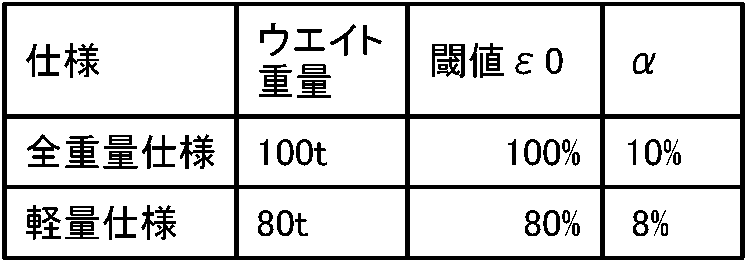
すなわち、全重量仕様モードでは、カウンタウエイト30の重量が100tであり、ひずみゲージ51が検出するひずみ量の閾値ε0(閾値εmax)が100%に設定されている。一方、軽量仕様モードでは、カウンタウエイト30の重量が80tであり、ひずみゲージ51が検出するひずみ量の閾値ε0(閾値εa)が80%に設定されている。なお、全重量仕様モードではαは10%に設定され、軽量仕様モードではαは8%に設定されている。
ステップS24またはS25においてε0が設定されると、装着判定部601は、ひずみゲージ51から出力される信号を受けることで、測定支台50のひずみ量εtを測定する(ステップS26)。そして、装着判定部601は、ひずみ量εtとカウンタウエイト30の重量に応じて予め設定された閾値ε0との大小関係を比較する(ステップS27)。本実施形態でも、第2実施形態と同様に閾値ε0に誤差αが設定されている。ここで、ε0-α≦εt≦ε0+αの場合(ステップS27でYES)、すなわち、ひずみゲージ51によって検出されるひずみ量εtが閾値ε0±αの範囲に含まれる場合に、装着判定部601は、カウンタウエイト30がウエイト装着部22Sに装着されたと判定する。更に、装着判定部601は、Flagの値を確認し(ステップS28)、Flagが1の場合には(ステップS28でYES)、情報出力部603が、「全重量仕様モードでのカウンタウエイト搭載完了情報」を表示部61に対して出力し、当該情報を表示部61に表示させる(ステップS29)。一方、ステップS28においてFlagが1でない場合には(ステップS28でNO)、情報出力部603が、「軽量仕様モードでのカウンタウエイト搭載完了情報」を表示部61に対して出力し、当該情報を表示部61に表示させる(ステップS30)。
なお、図15では、時刻t1において、ひずみゲージ51によって検出されるひずみ量εtが、ウエイトなし状態のεpから増大し閾値εmax±αの範囲に含まれているため、「全重量仕様モードでのカウンタウエイト搭載完了情報」が表示部61に表示される。このひずみ量εtの変化によって、装着判定部601はカウンタウエイト30がウエイト装着部22Sに装着されたことを検出することができる。なお、本実施形態でも、ステップS27において、εt<ε0-α、または、ε0+α<εtの場合(ステップS27でNO)は、ステップS26、S27が繰り返される。
以上のように、本実施形態では、操作部62(情報入力部)のモードスイッチ621が、ウエイト装着部22Sに装着されるウエイト体300の数に関するモード情報を受け付ける。当該モードスイッチ621は、少なくとも全重量仕様モードおよび軽量仕様モードを選択的に受け付け可能であり、全重量仕様モードでは前記複数のウエイト体300のうちのすべてのウエイト体300が前記ウエイト装着部22Sに装着され、軽量仕様モードでは前記複数のウエイト体300のうちの一部のウエイト体300が前記ウエイト装着部22Sに装着される。
そして、装着判定部601は、モードスイッチ621が全重量仕様モードを受け付けると前記ひずみゲージ51によって検出される前記ひずみ量εtと記憶部602から出力される前記全ウエイト用閾値εmaxとを比較することで前記すべてのウエイト体300が前記ウエイト装着部22Sに装着されたか否かを判定する。一方、装着判定部601は、モードスイッチ621が軽量仕様モードを受け付けると前記ひずみゲージ51によって検出される前記ひずみ量εtと記憶部602から出力される前記部分ウエイト用閾値εaとを比較することで前記一部のウエイト体300が前記ウエイト装着部22Sに装着されたか否かを判定する。このため、クレーン1において全重量仕様モードおよび軽量仕様モードの何れのモードが選択された場合であっても、ウエイト体300の重量に関する適切な閾値が採用され、ウエイト体300が装着されたか否かを判定することができる。
なお、本実施形態においても、ステップS27において、εp<εt<ε0-α(下限値よりも小さい)、または、ε0+α<εt(上限値よりも大きい)の場合(ステップS15でNO)、後記の実施形態のように情報出力部603が所定の警告情報(エラー情報)を出力してもよい。この場合も、装着されたカウンタウエイト30の重量が所定の誤差範囲を超える場合には、速やかに警告情報を出力することができる。
次に、本発明の第4実施形態について説明する。図19は、本実施形態に係るクレーン1においてカウンタウエイト30が装着される際のひずみ量の推移を示すグラフである。図20は、本実施形態に係るクレーン1においてカウンタウエイト30の装着が検出される様子を示すフローチャートである。なお、本実施形態では、ウエイト装着部22Sに対して、ウエイト体300が1つずつ順番に積載される。この際、ウエイト装着部22Sに装着されることが予定されるウエイト体300の数(段数N、積載予定数)は予め設定されており、作業者が操作部62から当該段数Nを入力する。
図20を参照して、クレーン1の組立作業が開始されると、制御部60の装着判定部601が、記憶部602に記憶されているFlagを0(ゼロ)にリセットする(ステップS31)。次に、作業者が操作部62のモードスイッチ621を押圧すると、カウンタウエイト30の自動検出モードが選択される(ステップS32でYES)。本実施形態でも、モードスイッチ621が押圧されるまで、装着判定部601はステップS32を繰り返す(ステップS32でNO)。モードスイッチ621が押圧されると、装着判定部601が記憶部602にそれぞれ記憶されている、変数n、閾値ε0および誤差変数α0をそれぞれ0に更新する(ステップS33)。また、本実施形態では、作業者によって、操作部62を通じてウエイト体300の段数N(最大数)が入力される(ステップS34)。当該段数Nは、前記ウエイト装着部22Sに装着されることが予定される前記ウエイト体300の数に関する情報に相当する。表3は、本実施形態において、記憶部602が記憶している情報を示したものである。
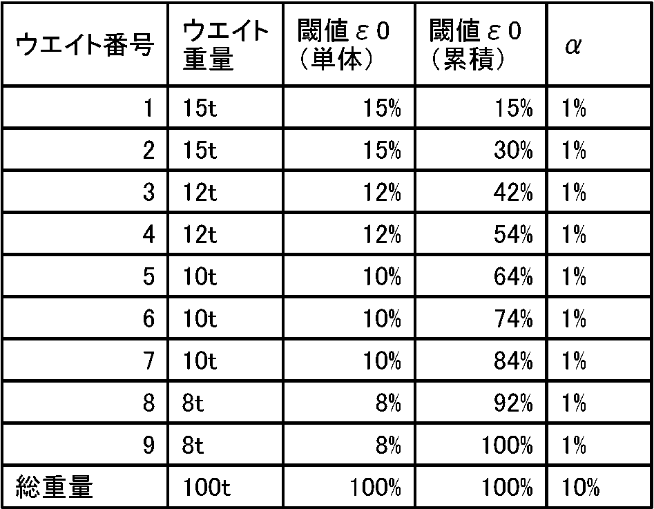
すなわち、表3では、段数Nが9まで選択可能なように設定されており、各ウエイト体300の重量が、8tから15tの範囲でそれぞれ設定されている。また、これらのウエイト体300が積載された場合の総重量が100tであり、当該総重量に対するひずみゲージ51のひずみ量εtが100%とされた場合、各ウエイト体300に対するひずみゲージ51のひずみ量ε0(閾値ε(n))は8%から15%の範囲に設定されている。また、表3では、1段目から順にウエイト体300が積載された場合のひずみゲージ51の累積ひずみ量が示されている。当該情報も記憶部602にそれぞれ格納されている。なお、いずれの場合もαは±1%に設定されている。
ステップS34において作業者によって入力された段数Nは、Nmaxとして記憶部602に記憶される。次に、装着判定部601は、変数nに1を加算するとともに(最初は0+1=1)、n=1における閾値ε0=ε(n)および誤差変数α0=α(n)を記憶部602から取得する(ステップS35)。なお、ε(n)およびα(n)は、いずれもn段目のウエイト体300に対応して予め設定された閾値(ひずみ量)および誤差である。1≦n≦Nのすべての範囲に対応して、各ウエイト体300が積載される順番に関する情報とともにこれら閾値および誤差に関する情報が、予め記憶部602に格納されている。
次に、装着判定部601は、ひずみゲージ51から出力される信号を受けることで、測定支台50のひずみ量εtを測定する(ステップS36)。当該ひずみ量εtの測定は、所定の時間間隔で継続的に実行される。この間、装着判定部601は、ひずみ量εtと、カウンタウエイト30の重量に応じて予め設定された閾値ε0との大小関係を比較する(ステップS37)。ここで、ε0-α0≦εt≦ε0+α0の場合(ステップS37でYES)、すなわち、ひずみゲージ51によって検出されるひずみ量εtが閾値ε0±α0の範囲に含まれる場合に、装着判定部601は、n段目のウエイト体300がウエイト装着部22Sに装着されたと判定する。
次に、装着判定部601は、nが記憶部602に記憶されている最大段数Nmaxに等しいか否かを判定する(ステップS38)。ここで、n=Nmaxの場合(ステップS38でYES)、装着判定部601は、閾値ε0および誤差変数α0をそれぞれεmaxおよびαmaxに更新する(ステップS39)。なお、閾値εmaxおよび誤差αmaxは、すべてのウエイト体300の総重量に対応する閾値(ひずみ量)および誤差であり、予め記憶部602に記憶されている。その後、記憶部602は、ひずみゲージ51によって検出されるひずみ量εtと、カウンタウエイト30の総重量に応じて予め設定された閾値ε0(εmax)との大小関係を比較する(ステップS40)。すなわち、n=Nmaxになると、積載されたすべてのウエイト体300の総重量に対するひずみ量εtが評価される。ここで、ε0-α0≦εt≦ε0+α0の場合(ステップS40でYES)、すなわち、ひずみゲージ51によって検出されるひずみ量εtが閾値ε0±α0の範囲に含まれる場合に、装着判定部601は、予定されているすべてのウエイト体300がウエイト装着部22Sに適切に装着されたと判定する。この結果、情報出力部603が、「全重量仕様モードでのカウンタウエイト搭載完了情報」を表示部61に対して出力し、当該情報を表示部61に表示させる(ステップS41)。
なお、図19では、作業者によって段数N(Nmax)が3に設定された上で、1段目から3段目までのウエイト体300がウエイト装着部22Sに順に積載される様子を示している。すなわち、時刻t1において、ひずみゲージ51によって検出されるひずみ量εtが、εpから増大し閾値ε(1)±αの範囲に含まれている。このひずみ量εtの変化によって、装着判定部601は1段目のウエイト体300がウエイト装着部22Sに装着されたことを判定することができる。同様に、時刻t2、t3において、ひずみ量εtが、閾値ε(2)±α、閾値ε(3)±αの範囲に含まれている。このひずみ量εtの変化によって、装着判定部601は2段目および3段目のウエイト体300がウエイト装着部22Sに装着されたことを判定することができる。なお、ステップS37において、εp<εt<ε0-α0、または、ε0+α0<εtの場合(ステップS37でNO)は、ステップS36、S37が繰り返される。また、ステップS38でnがNmaxに等しくない場合(ステップS38でNO)、nが1繰り上げられ(n=n+1)、ステップS35~S38が繰り返される。この結果、装着判定部601は、何枚のウエイト体300がウエイト装着部22Sに積載されたかを記憶部602に記憶することが可能となる。この積載枚数情報を情報出力部603が表示部61に表示させることで、当該情報を作業者に報知することができる。
更に、本実施形態では、ステップS40において、εp<εt<ε0-α0、またはε0+α0<εtの場合(ステップS40でNO)は、装着判定部601が、所定のエラー処理を実行する(ステップS42)。
図21は、本実施形態に係るクレーン1においてカウンタウエイト30の装着が検出される際のエラー処理を示すフローチャートである。図21を参照して、図20のステップS40において、εp<εt<ε0-α0、または、ε0+α0<εtの場合(ステップS40でNO)、装着判定部601は、ステップS50において、εt>ε0+α0か否かを判定する。そして、εt>ε0+α0の場合(ステップS50でYES)、図17に示すように積載されたカウンタウエイト30の重量が予め設定された閾値を超えているため、情報出力部603が表示部61に対して「重量超過情報」(警告情報)を出力し、表示部61に当該情報を表示させる。この場合、積載されたカウンタウエイト30の少なくとも一部のウエイト体300が予め設定されたものと異なっている可能性やウエイト体300の積載順序が誤っている可能性があるため、当該エラー情報によって作業者に注意喚起される。また、本実施形態が前述の軽量仕様モードにおいて実行された場合には、誤ってすべてのウエイト体300が積載された場合にも、当該「重量超過情報」が出力される。
一方、ステップS50において、εt<εt<ε0-α0の場合(ステップS50でNO)、図16に示すように積載されたカウンタウエイト30の重量が予め設定された閾値に届いていないこととなる。この場合、装着判定部601は、モードスイッチ621の出力を確認し、作業者によって自動検出モードの終了ボタンが押圧されたか否かを判定する(ステップS52)。ここで、作業者によって終了ボタンが押圧されている場合(ステップS52でYES)、情報出力部603が表示部61に対して「重量未達情報」(警告情報)を出力し、表示部61に当該情報を表示させる(ステップS53)。この場合も、積載されたカウンタウエイト30の少なくとも一部のウエイト体300が予め設定されたものと異なっている可能性やウエイト体300の積載順序が誤っている可能性があるため、当該エラー情報によって作業者に注意喚起される。また、本実施形態が前述の全重量仕様モードにおいて実行された場合には、作業者が軽量仕様モードと勘違いして、一部のウエイト体300が積載された場合にも、当該「重量未達情報」が出力される。なお、ステップS53が実行される状態には、積載されたカウンタウエイト30の重量が所定の閾値に届いていない場合であって、積載作業が完了したと作業者が錯誤し終了ボタンを押圧した場合、または作業者が意図的に自動検出モードを強制終了しようとした場合が含まれる。作業者は、「重量未達情報」を確認することで、作業が未了であることを認識することができる。
一方、ステップS52において作業者によって自動検出モードの終了ボタンが押圧されていない場合(ステップS52でNO)、装着判定部601は、所定時間が経過したか否かを判定する(ステップS54)。所定時間が経過した場合(ステップS54でYES)、積載されたカウンタウエイト30の重量が所定の閾値に届いていない場合であって、積載作業を作業者が終了したと思い待機している状態に相当する。したがって、情報出力部603が表示部61に対して「タイムアウト情報」を出力し、表示部61に当該情報を表示させる(ステップS55)。この場合、カウンタウエイト30の重量が未達の状態で所定時間放置されていることを、作業者が認識することで、作業の再開またはエラーの原因を確認することができる。
なお、ステップS51、S53およびS55が実行されると、装着判定部601は自動検出モードを終了する。また、ステップS54において、所定時間が経過していない場合(ステップS54でNO)、装着判定部601は、ステップS36以下を繰り返す。
以上のように、本実施形態では、記憶部602は、複数のウエイト体300のうちの各ウエイト体300の重量に対応する閾値であるウエイト単体用閾値ε(n)および各ウエイト体300が積載される順番をそれぞれ記憶している。そして、装着判定部601は、n番目(nは自然数)に積載されるウエイト体300に対して、(n-1)番目のウエイト体300が積載された状態からのひずみゲージ51によって検出される前記ひずみ量εtの増加分(変化量)と記憶部602から出力されるn番目のウエイト体300のウエイト単体用閾値ε(n)とを比較することで、各ウエイト体300がウエイト装着部22Sに装着されたか否かを判定する。なお、装着判定部601は、前記ひずみゲージ51によって検出される前記ひずみ量εtと記憶部602から出力される1番目からn番目までの前記ウエイト単体用閾値の合計(累積値)とを比較することで、各ウエイト体300がウエイト装着部22Sに装着されたか否かを判定してもよい。このような構成によれば、各ウエイト体300がウエイト装着部22Sに装着されることを個別に精度よく判定することができる。
また、上記のように、各ウエイト体300が積載される順番が管理されることなく、ウエイト体300が一つずつウエイト装着部22Sに装着されることが判定される態様でもよい。この場合、装着判定部601は、ひずみゲージ51によって検出されるひずみ量εtの変化量と記憶部602から出力されるウエイト単体用閾値とを比較すること、または、ひずみゲージ51によって検出されるひずみ量εtと記憶部602から出力された複数のウエイト単体用閾値の合計とを比較することで、各ウエイト体300がウエイト装着部22Sに装着されたか否かを判定する。
また、上記のように、(n-1)番目のウエイト体300の装着後、ひずみ量εtが変化したにも関わらず、n番目のウエイト体300がウエイト装着部22Sに装着されていないと装着判定部601が判定した場合に、情報出力部603が所定の誤積載情報を出力するものでもよい。この場合、n番目に装着されるべきウエイト体300とは異なるウエイト体300が装着された場合に、速やかに誤積載情報を出力することができる。
また、本実施形態に係るクレーン1のカウンタウエイト30の検出方法は、旋回フレーム22のうちウエイト装着部22Sよりも前方部分に、ウエイト装着部22Sへのカウンタウエイト30の装着に伴う旋回フレーム22の変形量を検出するひずみゲージ51(変形量検出部)を装着することと、ひずみゲージ51から出力された前記信号に応じて、カウンタウエイト30がウエイト装着部22Sに装着されたこと検出することと、を備える。当該検出方法によれば、旋回フレーム22のうちウエイト装着部22Sよりも前方部分の変形に基づいて、カウンタウエイト30の装着を検出することができる。また、カウンタウエイト30の装着に際して、カウンタウエイト30の重量に応じた直接的な衝撃がひずみゲージ51に付与されることはない。したがって、クレーン1の組立作業が繰り返し行われた場合であっても、ひずみゲージ51の破損が抑止される。また、ウエイト装着部22Sの周辺にひずみゲージ51が配置される場合と比較して、ひずみゲージ51から延びる電気配線が損傷することが抑止される。このため、クレーン1においてカウンタウエイト30の装着状態を安定して検出することができる。なお、上記の実施形態におけるクレーン1の各特徴も、当該検出方法に含まれる。
以上、本発明の実施形態に係るクレーン1、クレーン1のカウンタウエイト30の検出方法について説明した。なお、本発明はこれらの形態に限定されるものではない。本発明は、例えば以下のような変形実施形態を取ることができる。
上記の各実施形態では、変形量検出部としてひずみゲージ51を用いて説明したが、変形量検出部は、半導体ひずみゲージ、光ファイバー、ロードセルなどのように、ひずみゲージ51以外のセンサなどであってもよい。また、測定支台50は、第3内壁225Cに固定される態様にて説明したが、ウエイト装着部22Sよりも第1リング部21Aに近い位置で、底壁221、上壁222、左右一対の側壁223、第2内壁225B、第3内壁225などに固定されるものでもよい。また、ひずみゲージ51は測定支台50に装着されることなく、上記の底壁221、上壁222、左右一対の側壁223、第2内壁225B、第3内壁225などに直接装着される(貼り付けられる)ものでもよい。なお、ひずみゲージ51が測定支台50に装着される場合には、測定支台50の配置、形状や材料が調整され測定支台50の変形量を大きくすることができるため、測定支台50を備えずひずみゲージ51が旋回フレーム22に直接装着される場合よりもカウンタウエイト30が装着されたことを精度よく判定することができる。また、測定支台50およびひずみゲージ51の数は、2つ(左右一対)に限定されるものではなく、1つまたは3つ以上の測定支台50およびひずみゲージ51が配置されてもよい。
また、図22は、本発明の第1変形実施形態に係る旋回フレーム22の断面斜視図である。図22では、上下一対のひずみゲージ50Lが底壁221および上壁222に直接装着されている。このように、本発明に係る変形量検出部(ひずみゲージ)は、測定支台50を介さずに旋回フレーム22に直接装着される態様でもよい。この場合も、ひずみゲージ50Lは、旋回フレーム22のうちウエイト装着部22Sよりも前方部分、更には、ウエイト装着部22Sよりも第1リング部21Aに近い位置に装着されることが望ましい。
また、図23および図24は、それぞれ本発明の第2変形実施形態および第3変形実施形態に係る測定支台50Mおよび50Nを拡大した断面斜視図である。先の実施形態では、測定支台50の保持面50Cが湾曲面からなる態様にて説明したが、図23および図24に示すように、保持面50Cは傾斜した平面からなる態様でもよい。
また、図25は、本発明の第4変形実施形態に係る測定支台50Pを拡大した断面図である。本変形実施形態では、測定支台50Pは、第3内壁225Cの上端部と上壁222とが交差する角部に配置されている。この場合、ウエイト装着部22Sにカウンタウエイト30が装着されると、上壁222には図25の矢印D3方向に沿って力が付与される。この結果、測定支台50Pの保持面50Cには、矢印D4で示すような圧縮応力が発生する。そして、ひずみゲージ51は、当該圧縮応力に伴う保持面50Cの変形量を検出する。このような構成においても、カウンタウエイト30の装着に際して、カウンタウエイト30の重量に応じた直接的な衝撃がひずみゲージ51に付与されることはない。したがって、クレーン1の組立作業が繰り返し行われた場合であっても、ひずみゲージ51の破損が抑止される。また、ひずみゲージ51が図25の矢印D4方向に沿った保持面50Cの変形量を精度良く検出することができる。
本発明によって提供されるのは作業機械であって、当該作業機械は、上部本体であって、前記上部本体の後端部に配置されるウエイト装着部を有する、上部本体と、前記上部本体が鉛直方向に延びる旋回軸心回りに旋回可能なように前記上部本体を支持する下部本体と、前記ウエイト装着部よりも前方において前記上部本体に配置され、作業者が搭乗することを許容する運転室と、前記上部本体の前方部分に起伏可能に装着される起伏部材と、前記上部本体に固定される第1リング部と前記下部本体に固定される第2リング部とを有し、前記第1リング部は前記第2リング部に対して前記旋回軸心回りに相対回転可能である、旋回ベアリングと、前記上部本体の前記ウエイト装着部に着脱可能に装着されるカウンタウエイトと、前記上部本体のうち前記ウエイト装着部よりも前方部分に装着され、前記カウンタウエイトの前記ウエイト装着部への装着に伴う前記上部本体の変形量を検出する変形量検出部と、前記変形量検出部によって検出された前記変形量に基づいて、前記カウンタウエイトが前記ウエイト装着部に装着されたことを判定する装着判定部と、を備える。
本構成によれば、カウンタウエイトがウエイト装着部に装着されると、変形量検出部が上部本体の変形量を検出する。そして、装着判定部は、前記変形量検出部によって検出された変形量に基づいて、前記カウンタウエイトが前記ウエイト装着部に装着されたことを判定する。このため、上部本体のうちウエイト装着部よりも前方部分の変形に基づいて、カウンタウエイトの装着を検出することができる。また、上記の構成によれば、カウンタウエイトがウエイト装着部に装着される時に、カウンタウエイトの重量に応じた直接的な衝撃が変形量検出部に付与されることがない。したがって、作業機械の組立作業が繰り返し行われた場合であっても、変形量検出部の破損が抑止される。また、ウエイト装着部に変形量検出部が配置される場合と比較して、変形量検出部から延びる電気配線がカウンタウエイトと接触することで損傷することを防止することができる。このように、カウンタウエイトの装着状態を安定して検出することが可能な作業機械を提供することができる。更に、カウンタウエイトに装着されたRFIDタグの情報に応じてカウンタウエイトの装着状態が検出される技術と比較して、タグの損傷や脱離に伴う誤検出が防止される。
上記の構成において、前記変形量検出部はひずみゲージからなり、当該ひずみゲージは前記上部本体のうち前記ひずみゲージが装着された部分のひずみ量を前記変形量として検出することが望ましい。
本構成によれば、カウンタウエイトの大きな重量に対応した荷重計を備えることなく、カウンタウエイトの装着状態を簡易かつ低コストで検出することができる。
上記の構成において、前記カウンタウエイトの重量に対応する閾値を予め記憶および出力する記憶部を更に備え、前記装着判定部は、前記ひずみゲージによって検出される前記ひずみ量と前記記憶部から出力される前記閾値とを比較することで、前記カウンタウエイトが前記ウエイト装着部に装着されたか否かを判定することが望ましい。
本構成によれば、ひずみゲージが検出するひずみ量の変化に応じて、カウンタウエイトの装着を判定することができる。
上記の構成において、前記装着判定部は、前記ひずみゲージによって検出される前記ひずみ量が前記閾値を超えた場合に、前記カウンタウエイトが前記ウエイト装着部に装着されたと判定することが望ましい。
本構成によれば、検出されるひずみ量が閾値を超えることに対応して、カウンタウエイトの装着を速やかに判定することができる。
上記の構成において、前記閾値は、前記カウンタウエイトの重量に応じて予め設定された下限値および上限値を含み、前記装着判定部は、前記ひずみゲージによって検出される前記ひずみ量が前記下限値と前記上限値との間に含まれる場合に、前記カウンタウエイトが前記ウエイト装着部に装着されたと判定することが望ましい。
本構成によれば、カウンタウエイトの重量に製造誤差などがある場合であっても、カウンタウエイトの装着を安定して検出し、誤検知を防止することができる。
上記の構成において、前記ひずみゲージによって検出される前記ひずみ量が前記下限値よりも小さいまたは前記上限値よりも大きい場合に、所定の警告情報を出力する警告情報出力部を更に有することが望ましい。
本構成によれば、装着されたカウンタウエイトの重量が所定の誤差範囲を超える場合には、速やかに警告情報を出力することができる。
上記の構成において、前記カウンタウエイトは、前記ウエイト装着部に鉛直方向に沿って積載されることが可能な複数のウエイト体を有し、前記ウエイト装着部に装着される前記ウエイト体の数に関するモード情報を受け付ける情報入力部であって、当該情報入力部は、少なくとも最大装着モードおよび部分装着モードを選択的に受け付け可能であり、前記最大装着モードでは前記複数のウエイト体のうちのすべてのウエイト体が前記ウエイト装着部に装着され、前記部分装着モードでは前記複数のウエイト体のうちの一部のウエイト体が前記ウエイト装着部に装着される、情報入力部を更に備え、前記記憶部は、前記複数のウエイト体のうちの前記すべてのウエイト体の総重量に対応する前記閾値である全ウエイト用閾値と、前記複数のウエイト体のうちの前記一部のウエイト体の総重量に対応する前記閾値である部分ウエイト用閾値とを予め記憶しており、前記装着判定部は、前記情報入力部が前記最大装着モードを受け付けると前記ひずみゲージによって検出される前記ひずみ量と前記記憶部から出力される前記全ウエイト用閾値とを比較することで前記すべてのウエイト体が前記ウエイト装着部に装着されたか否かを判定する一方、前記情報入力部が前記部分装着モードを受け付けると前記ひずみゲージによって検出される前記ひずみ量と前記記憶部から出力される前記部分ウエイト用閾値とを比較することで前記一部のウエイト体が前記ウエイト装着部に装着されたか否かを判定することが望ましい。
本構成によれば、作業機械において最大装着モードおよび部分装着モードの何れのモードが選択された場合であっても、ウエイト体の重量に関する適切な閾値が採用され、ウエイト体が装着されたか否かを判定することができる。
上記の構成において、前記カウンタウエイトは、前記ウエイト装着部に鉛直方向に沿って順に積載されることが可能な複数のウエイト体を有し、前記ウエイト装着部に装着されることが予定される前記ウエイト体の数である積載予定数に関する情報を受け付ける情報入力部を更に備え、前記記憶部は、前記複数のウエイト体のうちの各ウエイト体の重量に対応する前記閾値であるウエイト単体用閾値をそれぞれ記憶しており、前記装着判定部は、前記ひずみゲージによって検出される前記ひずみ量の変化量と前記記憶部から出力される前記ウエイト単体用閾値とを比較すること、または、前記ひずみゲージによって検出される前記ひずみ量と前記記憶部から出力された複数の前記ウエイト単体用閾値の合計とを比較することで、前記各ウエイト体が前記ウエイト装着部に装着されたか否かを判定することが望ましい。
本構成によれば、各ウエイト体がウエイト装着部に装着されることを個別に精度よく判定することができる。
上記の構成において、前記記憶部は、前記複数のウエイト体のうちの各ウエイト体が積載される順番に関する情報を更に記憶しており、前記装着判定部は、n番目(nは自然数)に積載される前記ウエイト体に対して、(n-1)番目の前記ウエイト体が積載された状態からの前記ひずみゲージによって検出される前記ひずみ量の変化量と前記記憶部から出力されるn番目の前記ウエイト体の前記ウエイト単体用閾値とを比較すること、または、前記ひずみゲージによって検出される前記ひずみ量と前記記憶部から出力される1番目からn番目までの前記ウエイト単体用閾値の合計とを比較することで、前記n番目のウエイト体が前記ウエイト装着部に装着されたか否かを判定することが望ましい。
本構成によれば、各ウエイト体がウエイト装着部に所定の順番で装着されることを個別に精度よく判定することができる。
上記の構成において、(n-1)番目の前記ウエイト体の装着後、前記ひずみ量が変化したにも関わらず、前記n番目のウエイト体が前記ウエイト装着部に装着されていないと前記装着判定部が判定した場合に、所定の誤積載情報を出力する誤積載情報出力部を更に有することが望ましい。
本構成によれば、n番目に装着されるべきウエイト体とは異なるウエイト体が装着された場合に、速やかに誤積載情報を出力することができる。
上記の構成において、前記上部本体は、当該上部本体のうち前記ウエイト装着部よりも前記第1リング部に近い位置に配置され、前記ウエイト装着部への前記カウンタウエイトの装着に伴って前記上部本体とともに変形する変形部材を更に備え、前記変形量検出部は、前記変形部材に装着され、前記カウンタウエイトの装着に伴う前記変形部材の変形量を検出することが望ましい。
本構成によれば、変形部材の配置、形状や材料を調整し変形部材の変形量を大きくすることで、カウンタウエイトが装着されたことを精度よく判定することができる。
Claims (11)
- 上部本体であって、前記上部本体の後端部に配置されるウエイト装着部を有する、上部本体と、
前記上部本体が鉛直方向に延びる旋回軸心回りに旋回可能なように前記上部本体を支持する下部本体と、
前記ウエイト装着部よりも前方において前記上部本体に配置され、作業者が搭乗することを許容する運転室と、
前記上部本体の前方部分に起伏可能に装着される起伏部材と、
前記上部本体に固定される第1リング部と前記下部本体に固定される第2リング部とを有し、前記第1リング部は前記第2リング部に対して前記旋回軸心回りに相対回転可能である、旋回ベアリングと、
前記上部本体の前記ウエイト装着部に着脱可能に装着されるカウンタウエイトと、
前記上部本体のうち前記ウエイト装着部よりも前方部分に装着され、前記カウンタウエイトの前記ウエイト装着部への装着に伴う前記上部本体の変形量を検出する変形量検出部と、
前記変形量検出部によって検出された前記変形量に基づいて、前記カウンタウエイトが前記ウエイト装着部に装着されたことを判定する装着判定部と、
を備える、作業機械。 - 前記変形量検出部はひずみゲージからなり、当該ひずみゲージは前記上部本体のうち前記ひずみゲージが装着された部分のひずみ量を前記変形量として検出する、請求項1に記載の作業機械。
- 前記カウンタウエイトの重量に対応する閾値を予め記憶および出力する記憶部を更に備え、
前記装着判定部は、前記ひずみゲージによって検出される前記ひずみ量と前記記憶部から出力される前記閾値とを比較することで、前記カウンタウエイトが前記ウエイト装着部に装着されたか否かを判定する、請求項2に記載の作業機械。 - 前記装着判定部は、前記ひずみゲージによって検出される前記ひずみ量が前記閾値を超えた場合に、前記カウンタウエイトが前記ウエイト装着部に装着されたと判定する、請求項3に記載の作業機械。
- 前記閾値は、前記カウンタウエイトの重量に応じて予め設定された下限値および上限値を含み、
前記装着判定部は、前記ひずみゲージによって検出される前記ひずみ量が前記下限値と前記上限値との間に含まれる場合に、前記カウンタウエイトが前記ウエイト装着部に装着されたと判定する、請求項3に記載の作業機械。 - 前記ひずみゲージによって検出される前記ひずみ量が前記下限値よりも小さいまたは前記上限値よりも大きい場合に、所定の警告情報を出力する警告情報出力部を更に有する、請求項5に記載の作業機械。
- 前記カウンタウエイトは、前記ウエイト装着部に鉛直方向に沿って積載されることが可能な複数のウエイト体を有し、
前記ウエイト装着部に装着される前記ウエイト体の数に関するモード情報を受け付ける情報入力部であって、当該情報入力部は、少なくとも最大装着モードおよび部分装着モードを選択的に受け付け可能であり、前記最大装着モードでは前記複数のウエイト体のうちのすべてのウエイト体が前記ウエイト装着部に装着され、前記部分装着モードでは前記複数のウエイト体のうちの一部のウエイト体が前記ウエイト装着部に装着される、情報入力部を更に備え、
前記記憶部は、前記複数のウエイト体のうちの前記すべてのウエイト体の総重量に対応する前記閾値である全ウエイト用閾値と、前記複数のウエイト体のうちの前記一部のウエイト体の総重量に対応する前記閾値である部分ウエイト用閾値とを予め記憶しており、
前記装着判定部は、前記情報入力部が前記最大装着モードを受け付けると前記ひずみゲージによって検出される前記ひずみ量と前記記憶部から出力される前記全ウエイト用閾値とを比較することで前記すべてのウエイト体が前記ウエイト装着部に装着されたか否かを判定する一方、前記情報入力部が前記部分装着モードを受け付けると前記ひずみゲージによって検出される前記ひずみ量と前記記憶部から出力される前記部分ウエイト用閾値とを比較することで前記一部のウエイト体が前記ウエイト装着部に装着されたか否かを判定する、請求項3乃至6の何れか1項に記載の作業機械。 - 前記カウンタウエイトは、前記ウエイト装着部に鉛直方向に沿って順に積載されることが可能な複数のウエイト体を有し、
前記ウエイト装着部に装着されることが予定される前記ウエイト体の数である積載予定数に関する情報を受け付ける情報入力部を更に備え、
前記記憶部は、前記複数のウエイト体のうちの各ウエイト体の重量に対応する前記閾値であるウエイト単体用閾値をそれぞれ記憶しており、
前記装着判定部は、前記ひずみゲージによって検出される前記ひずみ量の変化量と前記記憶部から出力される前記ウエイト単体用閾値とを比較すること、または、前記ひずみゲージによって検出される前記ひずみ量と前記記憶部から出力された複数の前記ウエイト単体用閾値の合計とを比較することで、前記各ウエイト体が前記ウエイト装着部に装着されたか否かを判定する、請求項3乃至6の何れか1項に記載の作業機械。 - 前記記憶部は、前記複数のウエイト体のうちの各ウエイト体が積載される順番に関する情報を更に記憶しており、
前記装着判定部は、n番目(nは自然数)に積載される前記ウエイト体に対して、(n-1)番目の前記ウエイト体が積載された状態からの前記ひずみゲージによって検出される前記ひずみ量の変化量と前記記憶部から出力されるn番目の前記ウエイト体の前記ウエイト単体用閾値とを比較すること、または、前記ひずみゲージによって検出される前記ひずみ量と前記記憶部から出力される1番目からn番目までの前記ウエイト単体用閾値の合計とを比較することで、前記n番目のウエイト体が前記ウエイト装着部に装着されたか否かを判定する、請求項8に記載の作業機械。 - (n-1)番目の前記ウエイト体の装着後、前記ひずみ量が変化したにも関わらず、前記n番目のウエイト体が前記ウエイト装着部に装着されていないと前記装着判定部が判定した場合に、所定の誤積載情報を出力する誤積載情報出力部を更に有する、請求項9に記載の作業機械。
- 前記上部本体は、当該上部本体のうち前記ウエイト装着部よりも前記第1リング部に近い位置に配置され前記ウエイト装着部への前記カウンタウエイトの装着に伴って前記上部本体とともに変形する変形部材を更に備え、
前記変形量検出部は、前記変形部材に装着され、前記カウンタウエイトの装着に伴う前記変形部材の変形量を検出する、請求項1乃至10の何れか1項に記載の作業機械。
Applications Claiming Priority (2)
| Application Number | Priority Date | Filing Date | Title |
|---|---|---|---|
| JP2018083847A JP7119538B2 (ja) | 2018-04-25 | 2018-04-25 | 作業機械 |
| JP2018-083847 | 2018-04-25 |
Publications (1)
| Publication Number | Publication Date |
|---|---|
| WO2019208232A1 true WO2019208232A1 (ja) | 2019-10-31 |
Family
ID=68295432
Family Applications (1)
| Application Number | Title | Priority Date | Filing Date |
|---|---|---|---|
| PCT/JP2019/015748 Ceased WO2019208232A1 (ja) | 2018-04-25 | 2019-04-11 | 作業機械 |
Country Status (2)
| Country | Link |
|---|---|
| JP (1) | JP7119538B2 (ja) |
| WO (1) | WO2019208232A1 (ja) |
Families Citing this family (1)
| Publication number | Priority date | Publication date | Assignee | Title |
|---|---|---|---|---|
| CN112875538B (zh) * | 2021-01-05 | 2022-05-24 | 上海市机械施工集团有限公司 | 一种预制装配式高架箱梁吊装工艺 |
Citations (7)
| Publication number | Priority date | Publication date | Assignee | Title |
|---|---|---|---|---|
| JPH0434290U (ja) * | 1990-07-20 | 1992-03-23 | ||
| JPH1072187A (ja) * | 1996-08-29 | 1998-03-17 | Sumitomo Constr Mach Co Ltd | 移動式クレーンの転倒防止装置 |
| JP2007016895A (ja) * | 2005-07-07 | 2007-01-25 | Thermatronics Boeki Kk | 移動荷重を支える構造物及び該構造物を用いた装置 |
| JP2014218374A (ja) * | 2013-05-03 | 2014-11-20 | マニトワック・クレーン・グループ・フランス・ソシエテ・パール・アクシオン・サンプリフィエManitowoc Crane Group France SAS | クレーンの組立カウンタウェイトを確認及び監視するための装置及び方法 |
| JP2017095218A (ja) * | 2015-11-20 | 2017-06-01 | コベルコクレーン株式会社 | 作業機械のカウンタウエイト個数検出装置 |
| WO2017159321A1 (ja) * | 2016-03-18 | 2017-09-21 | 株式会社タダノ | カウンタウエイト組立補助装置 |
| JP2018016442A (ja) * | 2016-07-27 | 2018-02-01 | 日立住友重機械建機クレーン株式会社 | クレーン |
-
2018
- 2018-04-25 JP JP2018083847A patent/JP7119538B2/ja active Active
-
2019
- 2019-04-11 WO PCT/JP2019/015748 patent/WO2019208232A1/ja not_active Ceased
Patent Citations (7)
| Publication number | Priority date | Publication date | Assignee | Title |
|---|---|---|---|---|
| JPH0434290U (ja) * | 1990-07-20 | 1992-03-23 | ||
| JPH1072187A (ja) * | 1996-08-29 | 1998-03-17 | Sumitomo Constr Mach Co Ltd | 移動式クレーンの転倒防止装置 |
| JP2007016895A (ja) * | 2005-07-07 | 2007-01-25 | Thermatronics Boeki Kk | 移動荷重を支える構造物及び該構造物を用いた装置 |
| JP2014218374A (ja) * | 2013-05-03 | 2014-11-20 | マニトワック・クレーン・グループ・フランス・ソシエテ・パール・アクシオン・サンプリフィエManitowoc Crane Group France SAS | クレーンの組立カウンタウェイトを確認及び監視するための装置及び方法 |
| JP2017095218A (ja) * | 2015-11-20 | 2017-06-01 | コベルコクレーン株式会社 | 作業機械のカウンタウエイト個数検出装置 |
| WO2017159321A1 (ja) * | 2016-03-18 | 2017-09-21 | 株式会社タダノ | カウンタウエイト組立補助装置 |
| JP2018016442A (ja) * | 2016-07-27 | 2018-02-01 | 日立住友重機械建機クレーン株式会社 | クレーン |
Also Published As
| Publication number | Publication date |
|---|---|
| JP2019189397A (ja) | 2019-10-31 |
| JP7119538B2 (ja) | 2022-08-17 |
Similar Documents
| Publication | Publication Date | Title |
|---|---|---|
| KR100745847B1 (ko) | 조작지원장치 | |
| FI122872B (fi) | Menetelmä punnitusjärjestelmän tarkistuspunnituksessa ja ohjelmistotuote sekä järjestely punnitusjärjestelmän tarkistuspunnituksessa ja materiaalinkäsittelykone | |
| US10472214B2 (en) | Crane and method for monitoring the overload protection of such a crane | |
| JP5122786B2 (ja) | カウンタウェイトの着脱装置 | |
| CN112313166B (zh) | 起重机以及起重机的姿势变更方法 | |
| KR20090069823A (ko) | 로울러형 하중검출장치를 이용한 크레인의 안전제어시스템 | |
| CN115140654B (zh) | 绞车卷筒的监视装置 | |
| JP2014091632A (ja) | アウトリガパッド監視装置 | |
| EP3307667A1 (en) | System and method for the calculation of capacity charts at intermediate counterweight positions | |
| US11235961B2 (en) | Height adjustment assistance device, crane comprising same, and height adjustment method | |
| WO2019208232A1 (ja) | 作業機械 | |
| JP7189489B2 (ja) | 移動式クレーン及びクレーンシステム | |
| JP7102881B2 (ja) | 作業機械 | |
| JP6708987B2 (ja) | クレーンおよびクレーンの姿勢変更方法 | |
| JP2022018775A (ja) | 建設機械の重量計測装置及び建設機械 | |
| JP4372601B2 (ja) | 操作履歴保存装置 | |
| EP3805142B1 (en) | Mobile crane | |
| JP6984174B2 (ja) | クレーン | |
| US12139381B2 (en) | Mobile crane | |
| JP2001031389A (ja) | ブーム式作業車における支持荷重検出装置 | |
| JP7467835B2 (ja) | 移動式クレーン | |
| JP5025579B2 (ja) | カウンタウエイト着脱装置およびトラッククレーン | |
| JP2020011796A (ja) | 移動式クレーン | |
| JP2021191707A (ja) | 補助シリンダ制御装置、それを備えた作業機械、および、補助シリンダ制御方法 | |
| JP2021014346A (ja) | 移動式クレーン |
Legal Events
| Date | Code | Title | Description |
|---|---|---|---|
| 121 | Ep: the epo has been informed by wipo that ep was designated in this application |
Ref document number: 19792617 Country of ref document: EP Kind code of ref document: A1 |
|
| NENP | Non-entry into the national phase |
Ref country code: DE |
|
| 122 | Ep: pct application non-entry in european phase |
Ref document number: 19792617 Country of ref document: EP Kind code of ref document: A1 |