WO2019197856A1 - 回転電機 - Google Patents
回転電機 Download PDFInfo
- Publication number
- WO2019197856A1 WO2019197856A1 PCT/IB2018/000528 IB2018000528W WO2019197856A1 WO 2019197856 A1 WO2019197856 A1 WO 2019197856A1 IB 2018000528 W IB2018000528 W IB 2018000528W WO 2019197856 A1 WO2019197856 A1 WO 2019197856A1
- Authority
- WO
- WIPO (PCT)
- Prior art keywords
- shaft
- rotor
- power transmission
- rotor shaft
- peripheral surface
- Prior art date
Links
Images


Classifications
-
- H—ELECTRICITY
- H02—GENERATION; CONVERSION OR DISTRIBUTION OF ELECTRIC POWER
- H02K—DYNAMO-ELECTRIC MACHINES
- H02K7/00—Arrangements for handling mechanical energy structurally associated with dynamo-electric machines, e.g. structural association with mechanical driving motors or auxiliary dynamo-electric machines
- H02K7/003—Couplings; Details of shafts
-
- F—MECHANICAL ENGINEERING; LIGHTING; HEATING; WEAPONS; BLASTING
- F16—ENGINEERING ELEMENTS AND UNITS; GENERAL MEASURES FOR PRODUCING AND MAINTAINING EFFECTIVE FUNCTIONING OF MACHINES OR INSTALLATIONS; THERMAL INSULATION IN GENERAL
- F16D—COUPLINGS FOR TRANSMITTING ROTATION; CLUTCHES; BRAKES
- F16D1/00—Couplings for rigidly connecting two coaxial shafts or other movable machine elements
- F16D1/10—Quick-acting couplings in which the parts are connected by simply bringing them together axially
- F16D1/101—Quick-acting couplings in which the parts are connected by simply bringing them together axially without axial retaining means rotating with the coupling
-
- H—ELECTRICITY
- H02—GENERATION; CONVERSION OR DISTRIBUTION OF ELECTRIC POWER
- H02K—DYNAMO-ELECTRIC MACHINES
- H02K5/00—Casings; Enclosures; Supports
- H02K5/04—Casings or enclosures characterised by the shape, form or construction thereof
- H02K5/15—Mounting arrangements for bearing-shields or end plates
-
- H—ELECTRICITY
- H02—GENERATION; CONVERSION OR DISTRIBUTION OF ELECTRIC POWER
- H02K—DYNAMO-ELECTRIC MACHINES
- H02K5/00—Casings; Enclosures; Supports
- H02K5/04—Casings or enclosures characterised by the shape, form or construction thereof
- H02K5/16—Means for supporting bearings, e.g. insulating supports or means for fitting bearings in the bearing-shields
- H02K5/173—Means for supporting bearings, e.g. insulating supports or means for fitting bearings in the bearing-shields using bearings with rolling contact, e.g. ball bearings
- H02K5/1735—Means for supporting bearings, e.g. insulating supports or means for fitting bearings in the bearing-shields using bearings with rolling contact, e.g. ball bearings radially supporting the rotary shaft at only one end of the rotor
-
- F—MECHANICAL ENGINEERING; LIGHTING; HEATING; WEAPONS; BLASTING
- F16—ENGINEERING ELEMENTS AND UNITS; GENERAL MEASURES FOR PRODUCING AND MAINTAINING EFFECTIVE FUNCTIONING OF MACHINES OR INSTALLATIONS; THERMAL INSULATION IN GENERAL
- F16D—COUPLINGS FOR TRANSMITTING ROTATION; CLUTCHES; BRAKES
- F16D1/00—Couplings for rigidly connecting two coaxial shafts or other movable machine elements
- F16D1/10—Quick-acting couplings in which the parts are connected by simply bringing them together axially
- F16D2001/103—Quick-acting couplings in which the parts are connected by simply bringing them together axially the torque is transmitted via splined connections
-
- H—ELECTRICITY
- H02—GENERATION; CONVERSION OR DISTRIBUTION OF ELECTRIC POWER
- H02K—DYNAMO-ELECTRIC MACHINES
- H02K1/00—Details of the magnetic circuit
- H02K1/06—Details of the magnetic circuit characterised by the shape, form or construction
- H02K1/22—Rotating parts of the magnetic circuit
- H02K1/28—Means for mounting or fastening rotating magnetic parts on to, or to, the rotor structures
- H02K1/30—Means for mounting or fastening rotating magnetic parts on to, or to, the rotor structures using intermediate parts, e.g. spiders
-
- H—ELECTRICITY
- H02—GENERATION; CONVERSION OR DISTRIBUTION OF ELECTRIC POWER
- H02K—DYNAMO-ELECTRIC MACHINES
- H02K21/00—Synchronous motors having permanent magnets; Synchronous generators having permanent magnets
- H02K21/12—Synchronous motors having permanent magnets; Synchronous generators having permanent magnets with stationary armatures and rotating magnets
- H02K21/14—Synchronous motors having permanent magnets; Synchronous generators having permanent magnets with stationary armatures and rotating magnets with magnets rotating within the armatures
-
- H—ELECTRICITY
- H02—GENERATION; CONVERSION OR DISTRIBUTION OF ELECTRIC POWER
- H02K—DYNAMO-ELECTRIC MACHINES
- H02K7/00—Arrangements for handling mechanical energy structurally associated with dynamo-electric machines, e.g. structural association with mechanical driving motors or auxiliary dynamo-electric machines
- H02K7/08—Structural association with bearings
- H02K7/085—Structural association with bearings radially supporting the rotary shaft at only one end of the rotor
-
- H—ELECTRICITY
- H02—GENERATION; CONVERSION OR DISTRIBUTION OF ELECTRIC POWER
- H02K—DYNAMO-ELECTRIC MACHINES
- H02K7/00—Arrangements for handling mechanical energy structurally associated with dynamo-electric machines, e.g. structural association with mechanical driving motors or auxiliary dynamo-electric machines
- H02K7/10—Structural association with clutches, brakes, gears, pulleys or mechanical starters
- H02K7/116—Structural association with clutches, brakes, gears, pulleys or mechanical starters with gears
Definitions
- the present invention relates to a rotating electrical machine.
- JP2014-225971A discloses an electric motor including a rotor having a rotor shaft, a stator provided so as to surround the rotor, and a motor housing that houses the rotor and the stator.
- One end of the rotor shaft of the electric motor is connected to the rotating shaft of the transmission.
- the transmission is configured to decelerate the rotational power of the rotor shaft and transmit it to the drive shaft.
- a ball bearing that supports one end of the rotor shaft and a ball bearing that supports the other end of the rotor shaft are provided in the motor housing.
- the electric motor is configured such that the rotor shaft is rotatably supported by each of the one end side ball bearing and the other end side ball bearing which are arranged apart from each other in the shaft axis direction.
- the electric motor (rotating electric machine) having such a configuration since the ball bearings are disposed on one end side and the other end side of the rotor shaft, not only the overall configuration of the electric motor becomes complicated, but also the one end side and the other end when the motor is driven. Friction loss due to the ball bearing on the side will occur.
- An object of the present invention is to provide a rotating electrical machine that can suppress the occurrence of friction loss with a simple configuration.
- a rotating electrical machine that includes a rotor and a stator in a housing, and the rotor shaft of the rotor is connected to the power transmission shaft of the power transmission device.
- the housing of the rotating electrical machine is provided with a bearing, and one end portion of the rotor shaft is supported via the bearing.
- the other end of the rotor shaft is supported on the power transmission shaft by an inlay joint structure that is fitted to the power transmission shaft.
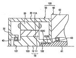
- FIG. 1 is a partial longitudinal sectional view of a motor system including a motor according to a first embodiment and a transmission.
- FIG. 2 is a partial vertical end view of a motor system including a motor according to a second embodiment and a transmission.
- FIG. 3 is a partial vertical end view of a motor system including a motor according to a third embodiment and a transmission.
- FIG. 4 is a partial vertical end view of a motor system including a motor according to a fourth embodiment and a transmission.
- FIG. 5 is a partial vertical end view of a motor system including a motor according to a fifth embodiment and a transmission.
- FIG. 1 is a partial longitudinal sectional view of a motor system 100 including a motor 50 and a transmission 60 according to the first embodiment of the present invention.
- the motor system 100 (rotary electric machine system) includes a motor 50 and a transmission 60, and constitutes a drive device for an electric vehicle, for example.
- the motor system 100 of the present embodiment will be described as an automobile system, the motor system 100 may be used as a drive device for devices other than vehicles, for example, various electric devices or industrial machines.
- the motor 50 rotates upon receiving power from a power source such as a battery mounted on the vehicle, and functions as an electric motor that drives the wheels of the vehicle.
- the motor 50 also functions as a generator that generates power by being driven by an external force. Therefore, the motor 50 is configured as a so-called motor generator (rotating electric machine) that functions as an electric motor and a generator.
- the motor 50 is configured as a motor generator for an electric vehicle.
- the motor 50 may be configured as a motor generator used for various electric devices or industrial machines.
- the motor 50 includes a rotor 10, a stator 20 disposed so as to surround the rotor 10, and a housing 30 that houses the rotor 10 and the stator 20.
- the rotor 10 includes a cylindrical rotor core 11 and a rotor shaft 12 fixed in the insertion hole 11A of the rotor core 11.
- the rotor 10 is disposed inside the stator 20 so as to be rotatable with respect to the stator 20.
- the rotor shaft 12 is configured as a shaft member that protrudes axially outward from both end surfaces of the rotor core 11.
- One end 121 (left end) of the rotor shaft 12 is rotatably supported by a bearing 40 provided in the housing 30, and the other end 122 (right end) of the rotor shaft 12 is connected to the rotating shaft 61 of the transmission 60. ing.
- the rotor shaft 12 and the rotation shaft 61 are arranged so that their rotation centers are located on the same line.
- the stator 20 is a cylindrical member formed by laminating a plurality of electromagnetic steel plates, and U-phase, V-phase, and W-phase coils are wound around the teeth of the stator 20.
- the stator 20 is fixed to the housing 30 with its outer peripheral surface in contact with the inner peripheral surface of the housing 30.
- the housing 30 is a case member that houses the rotor 10 and the stator 20.
- the motor 50 and the transmission 60 are disposed adjacent to each other, and the right side surface of the housing 30 is fixed to the left side surface of the transmission case 62 of the transmission 60 by fastening means such as bolts.
- a through hole 31 through which the other end 122 of the rotor shaft 12 passes to the outside of the housing 30 is formed on the right side surface of the housing 30.
- the transmission 60 includes a rotating shaft 61 and a plurality of gears (not shown) in a transmission case 62, and is configured as a power transmission device that shifts the rotational power of the rotor shaft 12 and transmits it to the drive shaft.
- the rotating shaft 61 is rotatably supported by a ball bearing 63 provided in the transmission case 62.
- a through-hole 64 is formed on the left side surface of the transmission case 62 to allow the left end portion (tip portion) of the rotating shaft 61 to pass outside the transmission case 62.
- the through hole 64 of the transmission case 62 is disposed so as to communicate with the through hole 31 of the housing 30.
- the motor 50 has a feature in the support structure of the rotor shaft 12 of the rotor 10, and the support structure of the rotor shaft 12 will be described below.
- the rotor shaft 12 of the motor 50 includes a central portion 123 that is fixed to the insertion hole 11 ⁇ / b> A of the rotor core 11 and an end portion 121 that extends from the central portion 123 to the side opposite to the transmission 60 side. And the other end portion 122 extending from the central portion 123 to the transmission 60 side.
- the outer diameters of the one end portion 121 and the other end portion 122 are smaller than the outer diameter of the central portion 123, and the one end portion 121 and the other end portion 122 are shaft members that are thinner than the central portion 123.
- a cylindrical bearing support portion 32 that supports the bearing 40 is formed on the inner side of the left side surface of the housing 30, and one end 121 of the rotor shaft 12 is supported by the bearing 40 that is fixed to the inner peripheral surface of the bearing support portion 32. It is supported rotatably.
- the bearing 40 is, for example, a single row ball bearing (deep groove ball bearing).
- the inner ring of the bearing 40 is attached to the outer peripheral surface of the one end portion 121, and the outer ring of the bearing 40 is attached to the inner peripheral surface of the bearing support portion 32. In this way, when viewed from the motor 50 alone, the rotor shaft 12 of the rotor 10 is in a state where only one end 121 is supported by the bearing 40.
- the other end 122 of the rotor shaft 12 is configured as a shaft member that gradually decreases in diameter toward the tip.
- the rotation shaft 61 of the transmission 60 has a shaft hole 61 ⁇ / b> A formed so as to be recessed in the axial direction at the left end, and the tip portion of the other end 122 of the rotor shaft 12 is formed at the end of the rotation shaft 61.
- the outer peripheral surface of the other end portion 122 is fitted to the inner peripheral surface of the shaft hole 61A.
- the other end 122 of the rotor shaft 12 is connected to the rotating shaft 61 by an inlay joint structure that is fitted to the rotating shaft 61 of the transmission 60.
- the shaft hole 61A of the rotating shaft 61 is linearly formed at a portion constituting the left end portion of the rotating shaft 61, but the center portion of the rotating shaft 61 or closer to the right end portion than the center portion from the left tip surface. It may be formed linearly up to the position. Therefore, the other end portion 122 of the rotor shaft 12 may be configured to be in-row connected to the shaft hole 61 ⁇ / b> A of the rotation shaft 61 at a center portion of the rotation shaft 61 or a position closer to the right end than the center portion.
- the other end portion 122 of the rotor shaft 12 has an inner peripheral surface of the shaft hole 61 ⁇ / b> A on the outer peripheral surface at a position closer to the central portion 123 than the tip, that is, a position different from a portion (inlay connecting portion) fitted to the rotary shaft 61.
- a spline portion 122A for spline coupling is provided. Relative rotation between the rotor shaft 12 and the rotating shaft 61 is restricted by spline coupling between the rotor shaft 12 and the rotating shaft 61 via the spline portion 122A.
- the spline part 122A is provided at a position near the tip of the other end part 122, and a part (inlay connection part) that fits the rotating shaft 61 is provided at a position closer to the center part 123 than the spline part 122A. May be.
- the restriction on the relative rotation between the rotor shaft 12 and the rotating shaft 61 is realized by a spline joint structure, but may be realized by a joint structure other than the spline joint structure.
- the joint structure other than the spline joint structure include a flange joint structure, an Oldham joint structure, and a low-tex joint structure.
- the motor 50 includes the rotor 10 and the stator 20 in the housing 30, and the housing 30 is provided with a bearing 40.
- One end 121 of the rotor shaft 12 is rotatably supported via a bearing 40, and the other end 122 of the rotor shaft 12 is connected to a rotating shaft 61 (power transmission shaft) of the transmission 60 (power transmission device). It is connected with the rotating shaft 61 by the inlay joint structure fitted with respect to. More specifically, in the motor 50, the other end portion 122 of the rotor shaft 12 is inserted into a shaft hole 61A formed at the end portion of the rotating shaft 61 of the transmission 60, and the outer peripheral surface of the other end portion 122 is the shaft hole.
- the rotor shaft 12 and the rotating shaft 61 are in-row connected by being fitted to the inner peripheral surface of 61A.
- the other end portion 122 of the rotor shaft 12 is in-row connected to the rotating shaft 61 of the transmission 60, so that it is not necessary to provide the housing 30 with a bearing for supporting the other end portion 122 of the rotor shaft 12. .
- both ends of the rotor shaft 12 can be rotatably supported by the bearing 40 for the one end 121 provided on the housing 30 and the rotating shaft 61 of the transmission 60.
- the bearing for the portion 122 can be omitted.
- the overall configuration of the motor 50 can be simplified.
- the frictional resistance during the rotation of the rotor shaft 12 can be reduced by the amount that the bearing for the other end 122 is not disposed, and the manufacturing cost of the motor 50 can also be reduced.
- the outer peripheral surface of the other end portion 122 at a position different from the portion fitted to the rotating shaft 61 of the transmission 60 is opposed to the inner peripheral surface of the shaft hole 61A.
- a spline portion 122A for spline coupling is formed.
- the other end portion 122 of the rotor shaft 12 is formed with a portion that is in-row connected to the rotating shaft 61 and a portion that is splined to the rotating shaft 61. Therefore, the connection range of the rotor shaft 12 with respect to the rotating shaft 61 is widened, and the other end portion 122 of the rotor shaft 12 can be supported more stably.
- a portion that fits into the shaft hole 61 ⁇ / b> A of the rotating shaft 61 is provided at a position closer to the rotating shaft 61 than the spline portion 122 ⁇ / b> A, for example, a tip portion of the other end portion 122.
- part supported by the rotating shaft 61 can be arrange
- the rotor shaft 12 can be supported at both ends in a state where the inclination of the rotor shaft 12 is further suppressed, and the rotor shaft 12 can be stably supported.
- the motor 50 of the second embodiment is different from the motor of the first embodiment in the way of the in-row connection between the other end 122 of the rotor shaft 12 and the rotating shaft 61 of the transmission 60.
- the other end portion 122 of the rotor shaft 12 is a shaft member having a smaller diameter than the central portion 123, and the tip portion of the other end portion 122 has an axial direction.
- a shaft hole 122 ⁇ / b> B that is recessed is formed.
- the left end portion (tip portion) of the rotating shaft 61 of the transmission 60 is inserted into the shaft hole 122B (inlay hole) of the other end portion 122 of the rotor shaft 12, and the shaft hole 122B positioned near the tip surface of the other end portion 122
- the inner peripheral surface of the rotary shaft 61 is fitted to the outer peripheral surface of the end of the rotating shaft 61.
- the other end 122 of the rotor shaft 12 is connected to the rotating shaft 61 by an inlay joint structure that is fitted to the rotating shaft 61 of the transmission 60.
- the shaft hole 122B of the rotor shaft 12 is linearly formed at a portion constituting the other end portion 122, but is closer to the end portion 121 than the center portion 123 of the rotor shaft 12 or the center portion 123 from the right tip end surface. It may be formed linearly up to the position. Therefore, the rotor shaft 12 may be configured to be in-row connected to the rotation shaft 61 of the transmission 60 at the center portion 123 or a position closer to the one end portion 121 than the center portion 123.
- the shaft hole 122B formed in the other end portion 122 of the rotor shaft 12 is located on the inner peripheral surface at a position closer to the center portion 123 than the tip, that is, a position different from a position (inlay connecting position) fitted to the rotating shaft 61.
- a spline portion 122C that is spline-coupled to the outer peripheral surface of the rotary shaft 61 is provided. Relative rotation between the rotor shaft 12 and the rotating shaft 61 is restricted by the spline coupling between the rotor shaft 12 and the rotating shaft 61 via the spline portion 122C.
- the spline part 122C is provided at a position near the tip of the other end part 122, and a part (an spigot connection part) that fits the rotating shaft 61 is provided at a position closer to the center part 123 than the spline part 122C. May be.
- the restriction on the relative rotation between the rotor shaft 12 and the rotating shaft 61 is realized by a spline joint structure, but may be realized by a joint structure other than the spline joint structure.
- the joint structure other than the spline joint structure include a flange joint structure, an Oldham joint structure, and a low-tex joint structure.
- the one end 121 of the rotor shaft 12 is rotatably supported via the bearing 40, and the other end 122 of the rotor shaft 12 is connected to the transmission 60 (power transmission). It is connected to the rotating shaft 61 by an inlay joint structure that is fitted to the rotating shaft 61 (power transmission shaft) of the apparatus. More specifically, the other end portion 122 of the rotor shaft 12 includes a shaft hole 122B into which the rotating shaft 61 is inserted, and the inner peripheral surface of the shaft hole 122B is fitted to the outer peripheral surface of the end portion of the rotating shaft 61. Thus, the rotor shaft 12 and the rotating shaft 61 are in-row connected.
- the other end portion 122 of the rotor shaft 12 is in-row connected to the rotating shaft 61 of the transmission 60, so that it is not necessary to provide the housing 30 with a bearing for supporting the other end portion 122 of the rotor shaft 12. It is possible to obtain the same operational effects as those of the first embodiment.
- the motor 50 according to the present embodiment has a configuration in which the shaft hole 122B of the other end 122 of the rotor shaft 12 is externally fitted to the end of the rotating shaft 61.
- the end 122 can be formed to an arbitrary thickness. As a result, the connection strength between the other end 122 of the rotor shaft 12 and the rotating shaft 61 of the transmission 60 can be increased as necessary.
- the other end portion 122 can be easily formed to an arbitrary thickness within a range in which the outer diameter is not larger than that of the central portion 123.
- the other end portion 122 and the central portion 123 of the rotor shaft 12 have the same outer diameter, only the one end portion 121 may be formed with a smaller diameter than other portions, and the manufacturing cost of the rotor shaft 12 is reduced. be able to.
- the connection strength when only the end of the rotary shaft 61 is formed thick in the rotary shaft 61 having a substantially constant outer diameter, the manufacturing cost increases. Therefore, according to the rotor shaft 12 according to the present embodiment, it is possible to increase the connection strength between the rotor shaft 12 and the rotary shaft 61 without increasing the manufacturing cost.
- the shaft hole 122B of the other end portion 122 of the rotor shaft 12 has an inner peripheral surface at a position different from a portion where the rotary shaft 61 is fitted to the outer peripheral surface of the rotary shaft 61.
- a spline portion 122C for spline coupling.
- the other end portion 122 of the rotor shaft 12 is formed with a portion that is in-row connected to the rotating shaft 61 and a portion that is splined to the rotating shaft 61. Therefore, the connection range of the rotor shaft 12 with respect to the rotating shaft 61 is widened, and the other end portion 122 of the rotor shaft 12 can be supported more stably.
- a portion of the other end portion 122 of the rotor shaft 12 that is fitted to the rotating shaft 61 is provided at a position closer to the rotating shaft 61 than the spline portion 122C, for example, a shaft hole 122B at the tip portion of the other end portion 122.
- part supported by the rotating shaft 61 can be arrange
- the rotor shaft 12 can be supported at both ends in a state where the inclination of the rotor shaft 12 is further suppressed, and the rotor shaft 12 can be stably supported.
- a motor system 100 including the motor 50 and the transmission 60 according to the third embodiment will be described with reference to FIG.
- the motor 50 of the third embodiment is different from the motor of the first embodiment in the structure of the bearing 40 that supports the one end 121 of the rotor shaft 12.
- the bearing 40 that supports the one end 121 of the rotor shaft 12 is not a single-row ball bearing but a double-row angular ball bearing.
- rolling elements (balls) provided between the inner ring and the outer ring are provided in a plurality of rows (for example, two rows) in the shaft axis direction, and contact points of the inner ring, the rolling elements, and the outer ring are provided in each row.
- the connecting straight lines (lines A and B) have an inclination with respect to the shaft radial direction.
- the line A in the outer row is inclined toward the other end 122 as it goes from the inner ring to the outer ring
- the line B in the inner row is inclined toward the one end 121 as it goes from the inner ring to the outer ring.
- the bearing 40 that supports the one end 121 of the rotor shaft 12 is configured as a double-row angular ball bearing, so that even when axial force acts on the rotor shaft 12.
- the double row angular ball bearing can receive the force. Thereby, the rotor shaft 12 can be supported more stably.
- the rotor shaft 12 is cantilevered with respect to the housing 30 via the bearing 40. If one end 121 of the rotor shaft 12 is not firmly supported by the bearing 40, the other end 122 side of the rotor shaft 12 may swing and the rotor core 11 attached to the rotor shaft 12 may interfere with the stator 20. There is.
- the bearing 40 is configured as a double row angular ball bearing, the one end 121 can be firmly supported without the other end 122 of the rotor shaft 12 swinging. Therefore, it is possible to suppress interference between the rotor core 11 and the stator 20 before the rotor shaft 12 is connected to the rotation shaft 61 of the transmission 60.
- a motor system 100 including a motor 50 and a transmission 60 according to the fourth embodiment will be described with reference to FIG.
- the motor 50 according to the fourth embodiment is different from the motor according to the first embodiment in the configuration of the bearing 40 that supports the one end 121 of the rotor shaft 12.
- the bearing 40 that supports the one end 121 of the rotor shaft 12 is composed of two single-row ball bearings 41 and 42 (deep groove ball bearings).
- the ball bearings 41 and 42 are provided so that each inner ring is in contact with the outer peripheral surface of the one end 121 of the rotor shaft 12, and are arranged side by side in the shaft axial direction.
- a gap adjusting member 70 for forming a predetermined gap between the ball bearings 41, 42 is provided on the outer peripheral surface of the rotor shaft 12 between the ball bearings 41, 42.
- the spacing adjusting member 70 is disposed so as to contact the right side surface (inner side surface) of the inner ring of the ball bearing 42 and the left side surface (outer side surface) of the inner ring of the ball bearing 41. Note that the right side surface (inner side surface) of the inner ring of the ball bearing 41 is in contact with a stepped portion 124 formed at one end 121 of the rotor shaft 12.
- the outer rings of the ball bearings 41 and 42 are housed in housing grooves 32 ⁇ / b> A formed on the inner peripheral surface of the bearing support portion 32 of the housing 30. Between the outer ring of the ball bearing 41 and the outer ring of the ball bearing 42, there is a gap corresponding to the width of the interval adjusting member 70. The right side surface (inner side surface) of the outer ring of the ball bearing 41 is in contact with the side surface of the housing groove 32A.
- annular disc spring 80 for applying a preload to the ball bearings 41 and 42 is provided in the receiving groove 32A of the bearing support portion 32.
- the disc spring 80 is sandwiched between the side surface of the housing groove 32A and the outer ring of the ball bearing 42, and urges the left side surface of the outer ring of the ball bearing 42 toward the right side in the shaft axial direction. Due to the urging force of the disc spring 80, a preload directed in the right direction is applied to the outer ring of the ball bearing 42.
- a reaction force from the side surface of the housing groove 32A acts on the outer ring of the ball bearing 41, and a preload is applied in the left direction. Become. In this way, by applying a preload to the outer rings of the ball bearings 41 and 42 using the disc spring 80, the internal clearance in the ball bearings 41 and 42 can be reduced.
- the one end 121 of the rotor shaft 12 is supported by the single row ball bearings 41 and 42 arranged in parallel in the shaft axial direction.
- the other end 122 side of the rotor shaft 12 may swing and the rotor core 11 and the stator 20 may interfere with each other.
- the rotor shaft 12 is made to suppress vibration of the other end portion 122 of the rotor shaft 12. Can support firmly. Therefore, it is possible to suppress interference between the rotor core 11 and the stator 20 before the rotor shaft 12 is connected to the rotation shaft 61 of the transmission 60.
- the bearing 40 is configured by two single-row ball bearings 41 and 42 arranged in parallel in the axial direction, but by three or more single-row ball bearings arranged in parallel in the axial direction. It may be configured.
- a disc spring 80 is provided in the housing 30, and the disc race 80 urges the outer rings of the ball bearings 41 and 42 in the shaft axial direction.
- the disc spring 80 is configured to bias the outer ring of the ball bearing 42, but may be configured to bias the inner ring of the ball bearing 42.
- the interval adjusting member 70 is disposed so as to be sandwiched between the outer ring of the ball bearing 41 and the outer ring of the ball bearing 42.
- the member that urges the ball bearing 42 or the like may be an elastic member such as a coil spring instead of the disc spring 80.
- a motor system 100 including a motor 50 and a transmission 60 according to a fifth embodiment will be described with reference to FIG.
- the motor 50 of the fifth embodiment is different from the motor of the second embodiment in the structure that supports the rotor core 11.
- the motor 50 is mainly characterized by the structure of the rotor 10, and the rotor 10 includes a rotor core 11, a rotor shaft 12, a core support portion 13, and a connection portion 14. Has been.
- the core support portion 13 of the rotor 10 has a cylindrical shape and is a member that supports the cylindrical rotor core 11 from the inside.
- the core support portion 13 is formed such that its axial length is slightly longer than the axial length of the rotor core 11.
- the core support portion 13 is inserted into the insertion hole 11 ⁇ / b> A of the rotor core 11, and the rotor core 11 is fixed on the core support portion 13 in a state of being externally fitted to the outer periphery of the core support portion 13.
- the rotor shaft 12 is disposed inside the core support portion 13, and the rotor shaft 12 and the core support portion 13 are connected via a connection portion 14.
- the connecting portion 14 is formed as a disk-like wall portion protruding in the shaft radial direction from the outer peripheral surface of the central portion 123 of the rotor shaft 12, and the inner peripheral surface of the central portion 123 of the rotor shaft 12 and the core support portion 13. Connect to the peripheral surface.
- the plate thickness of the connection portion 14 is set to be thinner than the axial lengths of the rotor shaft 12 and the core support portion 13.
- one end 121 is supported by the bearing 40, and the other end 122 is in-row connected to the rotary shaft 61 in a state of circumscribing the end of the rotary shaft 61 of the transmission 60.
- the connection of the rotor shaft 12 and the rotating shaft 61 it is possible to apply the technical thought of each embodiment mentioned above.
- the housing 30 is formed by a left housing 30L and a right housing 30R, and a central portion 33 of the left housing 30L is recessed in the shaft axial direction so as to enter the inside of the core support portion 13. .
- a bearing support portion 32 is formed in the central portion 33 of the left housing 30L, and the bearing 40 is fixed to the bearing support portion 32. That is, the bearing 40 is provided in the central portion 33 of the left housing 30 ⁇ / b> L so as to be positioned inside the rotor core 11 and the core support portion 13.
- the bearing 40 is configured as a double-row angular ball bearing.
- the bearing 40 may be one or more single row ball bearings (deep groove ball bearings) or the like instead of the double row angular ball bearings.
- the rotor 10 is a core support portion 13 that supports the rotor core 11 from the inside, and a disk-like member that protrudes from the outer peripheral surface of the rotor shaft 12 in the shaft radial direction, A connecting portion that connects the outer peripheral surface of the rotor shaft and the inner peripheral surface of the core support portion;
- the left housing 30L constituting the housing 30 is formed such that a central portion 33 (part) enters the inside of the core support portion 13, and the bearing 40 is provided in the central portion 33 that enters the inside of the core support portion 13. .
- variety in the axial direction of motor 50 itself is made into another implementation. It can be made thinner than the motor of the form. As a result, the motor 50 can be made compact.
- the rotor core 11, the stator 20, and the core support portion 13 described in each of the above embodiments are cylindrical members, but may be polygonal cylindrical members.
- the motor 50 is assembled to the transmission 60 as a power transmission device, but the motor 50 may be assembled to a power transmission device such as a speed reducer. Also in this case, the rotor shaft 12 of the motor 50 and the rotating shaft of the reduction gear can be connected by applying the technical idea in each embodiment.
Landscapes
- Engineering & Computer Science (AREA)
- Power Engineering (AREA)
- General Engineering & Computer Science (AREA)
- Mechanical Engineering (AREA)
- Connection Of Motors, Electrical Generators, Mechanical Devices, And The Like (AREA)
- Motor Or Generator Frames (AREA)
Abstract
Description
図1は、本発明の第1実施形態によるモータ50と、変速機60とを備えるモータシステム100の一部縦断面図である。
次に、図2を参照して、第2実施形態によるモータ50と、変速機60とを備えるモータシステム100について説明する。第2実施形態のモータ50と第1実施形態のモータとは、ロータシャフト12の他端部122と変速機60の回転軸61とのインロー接続の仕方において相違する。
次に、図3を参照して、第3実施形態によるモータ50と、変速機60とを備えるモータシステム100について説明する。第3実施形態のモータ50と第1実施形態のモータとは、ロータシャフト12の一端部121を支持するベアリング40の構造において相違する。
次に、図4を参照して、第4実施形態によるモータ50と、変速機60とを備えるモータシステム100について説明する。第4実施形態のモータ50と第1実施形態のモータとは、ロータシャフト12の一端部121を支持するベアリング40の構成において相違する。
次に、図5を参照して、第5実施形態によるモータ50と、変速機60とを備えるモータシステム100について説明する。第5実施形態のモータ50と第2実施形態のモータとは、ロータコア11を支持する構造において相違する。
Claims (11)
- ハウジング内にロータ及びステータを備え、前記ロータのロータシャフトが動力伝達装置の動力伝達シャフトに接続される回転電機であって、
前記ハウジングにはベアリングが設けられ、
前記ロータシャフトの一端部は、前記ベアリングを介して支持されており、
前記ロータシャフトの他端部は、前記動力伝達シャフトに対して嵌合するインロー継手構造により前記動力伝達シャフトに支持される、
回転電機。 - 請求項1に記載の回転電機であって、
前記ロータシャフトの他端部は、前記動力伝達シャフトの端部に形成されたシャフト孔に挿入され、
前記他端部の外周面は、前記シャフト孔の内周面に対して嵌合する、
回転電機。 - 請求項2に記載の回転電機であって、
前記動力伝達シャフトに嵌合する部位とは異なる位置における前記他端部の外周面には、前記シャフト孔の内周面に対してスプライン結合するスプライン部が形成される、
回転電機。 - 請求項3に記載の回転電機であって、
前記動力伝達シャフトに嵌合する部位は、前記スプライン部よりも前記動力伝達シャフト寄りの位置に設けられる、
回転電機。 - 請求項1に記載の回転電機であって、
前記ロータシャフトの他端部は、前記動力伝達シャフトの端部が挿入されるシャフト孔を備え、
前記シャフト孔の内周面は、前記動力伝達シャフトの端部の外周面に対して嵌合する、
回転電機。 - 請求項5に記載の回転電機であって、
前記動力伝達シャフトに嵌合する部位とは異なる位置における前記シャフト孔の内周面には、前記動力伝達シャフトの外周面に対してスプライン結合するスプライン部が形成される、
回転電機。 - 請求項6に記載の回転電機であって、
前記動力伝達シャフトに嵌合する部位は、前記スプライン部よりも前記動力伝達シャフト寄りの位置に設けられる、
回転電機。 - 請求項1から7のいずれか一つに記載の回転電機であって、
前記ベアリングは、複列アンギュラボールベアリングとして構成される、
回転電機。 - 請求項1から7のいずれか一つに記載の回転電機であって、
前記ベアリングは、シャフト軸方向に複数並設された単列ボールベアリングにより構成される、
回転電機。 - 請求項9に記載の回転電機であって、
前記ボールベアリングの内輪又は外輪は、前記ハウジングに設けられたばねによりシャフト軸方向に付勢される、
回転電機。 - 請求項1から10のいずれか一つに記載の回転電機であって、
前記ロータは、
筒状のロータコアを内側から支持する筒状のコア支持部と、
前記ロータシャフトの外周面からシャフト径方向に突出する円板状部材であって、前記ロータシャフトの外周面と前記コア支持部の内周面とを接続する接続部と、を備え、
前記ハウジングは、当該ハウジングの一部が前記コア支持部の内側に入り込むように形成され、
前記ベアリングは、前記ハウジングにおける前記コア支持部の内側に入り込んだ部位に設けられる、
回転電機。
Priority Applications (3)
| Application Number | Priority Date | Filing Date | Title |
|---|---|---|---|
| PCT/IB2018/000528 WO2019197856A1 (ja) | 2018-04-12 | 2018-04-12 | 回転電機 |
| EP18914738.2A EP3780357A4 (en) | 2018-04-12 | 2018-04-12 | ELECTRIC LATHE |
| JP2020512931A JP6962454B2 (ja) | 2018-04-12 | 2018-04-12 | 回転電機 |
Applications Claiming Priority (1)
| Application Number | Priority Date | Filing Date | Title |
|---|---|---|---|
| PCT/IB2018/000528 WO2019197856A1 (ja) | 2018-04-12 | 2018-04-12 | 回転電機 |
Publications (1)
| Publication Number | Publication Date |
|---|---|
| WO2019197856A1 true WO2019197856A1 (ja) | 2019-10-17 |
Family
ID=68163507
Family Applications (1)
| Application Number | Title | Priority Date | Filing Date |
|---|---|---|---|
| PCT/IB2018/000528 WO2019197856A1 (ja) | 2018-04-12 | 2018-04-12 | 回転電機 |
Country Status (3)
| Country | Link |
|---|---|
| EP (1) | EP3780357A4 (ja) |
| JP (1) | JP6962454B2 (ja) |
| WO (1) | WO2019197856A1 (ja) |
Cited By (2)
| Publication number | Priority date | Publication date | Assignee | Title |
|---|---|---|---|---|
| CN113710909A (zh) * | 2020-04-21 | 2021-11-26 | 华为数字能源技术有限公司 | 一种动力总成和车辆 |
| EP4068587A4 (en) * | 2019-11-26 | 2022-11-30 | NISSAN MOTOR Co., Ltd. | ROTARY ELECTRIC MACHINE |
Families Citing this family (1)
| Publication number | Priority date | Publication date | Assignee | Title |
|---|---|---|---|---|
| EP4274067A1 (de) * | 2022-05-04 | 2023-11-08 | Andreas Stihl AG & Co. KG | Arbeitsgerät |
Citations (7)
| Publication number | Priority date | Publication date | Assignee | Title |
|---|---|---|---|---|
| JPS6018640A (ja) * | 1983-07-08 | 1985-01-30 | Toshiba Corp | 駆動装置 |
| JP2002291192A (ja) * | 2001-03-28 | 2002-10-04 | Showa Corp | 電動パワーステアリング装置 |
| JP2009154604A (ja) * | 2007-12-25 | 2009-07-16 | Jtekt Corp | 車両用操舵装置 |
| JP2014004895A (ja) * | 2012-06-22 | 2014-01-16 | Aisin Seiki Co Ltd | 車両用駆動力伝達構造 |
| JP2014096964A (ja) * | 2012-11-12 | 2014-05-22 | Toyota Motor Corp | 動力伝達装置 |
| JP2014225971A (ja) | 2013-05-16 | 2014-12-04 | 本田技研工業株式会社 | 電動機 |
| WO2015146467A1 (ja) * | 2014-03-25 | 2015-10-01 | 本田技研工業株式会社 | 車輛用動力伝達装置 |
Family Cites Families (7)
| Publication number | Priority date | Publication date | Assignee | Title |
|---|---|---|---|---|
| JPS5977620U (ja) * | 1982-11-18 | 1984-05-25 | 光洋精工株式会社 | スプラインフイツテイング |
| JPH03102086U (ja) * | 1990-02-08 | 1991-10-24 | ||
| EP2595286A3 (en) * | 2005-05-10 | 2016-04-06 | Komatsu Ltd. | Engine with generator/motor as auxiliary power unit |
| JP2007062477A (ja) * | 2005-08-30 | 2007-03-15 | Nsk Ltd | ステアリング装置 |
| JP5267787B2 (ja) * | 2008-09-24 | 2013-08-21 | 株式会社ジェイテクト | 減速装置へのモータ取付方法、モータ取付構造及び電動パワーステアリング装置 |
| JP5177007B2 (ja) * | 2009-02-20 | 2013-04-03 | 日本精工株式会社 | 電動モータ及び電動パワーステアリング装置 |
| JP5741826B2 (ja) * | 2011-04-05 | 2015-07-01 | 日本電産株式会社 | モータ |
-
2018
- 2018-04-12 JP JP2020512931A patent/JP6962454B2/ja active Active
- 2018-04-12 WO PCT/IB2018/000528 patent/WO2019197856A1/ja active Application Filing
- 2018-04-12 EP EP18914738.2A patent/EP3780357A4/en active Pending
Patent Citations (7)
| Publication number | Priority date | Publication date | Assignee | Title |
|---|---|---|---|---|
| JPS6018640A (ja) * | 1983-07-08 | 1985-01-30 | Toshiba Corp | 駆動装置 |
| JP2002291192A (ja) * | 2001-03-28 | 2002-10-04 | Showa Corp | 電動パワーステアリング装置 |
| JP2009154604A (ja) * | 2007-12-25 | 2009-07-16 | Jtekt Corp | 車両用操舵装置 |
| JP2014004895A (ja) * | 2012-06-22 | 2014-01-16 | Aisin Seiki Co Ltd | 車両用駆動力伝達構造 |
| JP2014096964A (ja) * | 2012-11-12 | 2014-05-22 | Toyota Motor Corp | 動力伝達装置 |
| JP2014225971A (ja) | 2013-05-16 | 2014-12-04 | 本田技研工業株式会社 | 電動機 |
| WO2015146467A1 (ja) * | 2014-03-25 | 2015-10-01 | 本田技研工業株式会社 | 車輛用動力伝達装置 |
Non-Patent Citations (1)
| Title |
|---|
| See also references of EP3780357A4 |
Cited By (3)
| Publication number | Priority date | Publication date | Assignee | Title |
|---|---|---|---|---|
| EP4068587A4 (en) * | 2019-11-26 | 2022-11-30 | NISSAN MOTOR Co., Ltd. | ROTARY ELECTRIC MACHINE |
| JP7447914B2 (ja) | 2019-11-26 | 2024-03-12 | 日産自動車株式会社 | 電動車両の駆動装置 |
| CN113710909A (zh) * | 2020-04-21 | 2021-11-26 | 华为数字能源技术有限公司 | 一种动力总成和车辆 |
Also Published As
| Publication number | Publication date |
|---|---|
| JPWO2019197856A1 (ja) | 2021-04-15 |
| JP6962454B2 (ja) | 2021-11-10 |
| EP3780357A4 (en) | 2021-04-07 |
| EP3780357A1 (en) | 2021-02-17 |
Similar Documents
| Publication | Publication Date | Title |
|---|---|---|
| US8807253B2 (en) | In-wheel motor drive device | |
| JP4799199B2 (ja) | インホイールモータ駆動装置 | |
| WO2019197856A1 (ja) | 回転電機 | |
| JP2010032038A (ja) | サイクロイド減速機、インホイールモータ駆動装置、および車両用モータ駆動装置 | |
| US20140162826A1 (en) | Motor assembly with speed reducer | |
| WO2012140771A1 (ja) | 動力伝達装置 | |
| WO2020225582A1 (ja) | 回転電機 | |
| JP2012037016A (ja) | 車両の駆動装置 | |
| JP5572190B2 (ja) | 回転電機 | |
| JP7447914B2 (ja) | 電動車両の駆動装置 | |
| JP2008168821A (ja) | インホイールモータ駆動装置 | |
| JP6233324B2 (ja) | 車両の回転軸の支持構造 | |
| JP5169503B2 (ja) | 駆動輪用軸受装置 | |
| JP5142274B2 (ja) | サイクロイド減速機 | |
| WO2018084096A1 (ja) | 複合変速モジュール | |
| JP2007221947A (ja) | 電動モータ | |
| JP2012097903A (ja) | インホイールモータ駆動装置 | |
| WO2021095674A1 (ja) | インホイールモータ駆動装置 | |
| JPS63235754A (ja) | 遊星ロ−ラ式動力伝達装置 | |
| JP2024070029A (ja) | 減速装置 | |
| JP5830133B2 (ja) | インホイールモータ駆動装置 | |
| JP2010196863A (ja) | 継手構造 | |
| JP2022155794A (ja) | 車両駆動装置 | |
| JP2020128793A (ja) | 動力伝達装置 | |
| JP2019078324A (ja) | 車両用動力伝達装置 |
Legal Events
| Date | Code | Title | Description |
|---|---|---|---|
| 121 | Ep: the epo has been informed by wipo that ep was designated in this application |
Ref document number: 18914738 Country of ref document: EP Kind code of ref document: A1 |
|
| ENP | Entry into the national phase |
Ref document number: 2020512931 Country of ref document: JP Kind code of ref document: A |
|
| NENP | Non-entry into the national phase |
Ref country code: DE |
|
| WWE | Wipo information: entry into national phase |
Ref document number: 2018914738 Country of ref document: EP |
|
| ENP | Entry into the national phase |
Ref document number: 2018914738 Country of ref document: EP Effective date: 20201112 |